
AS-1400 - Earphones Galaxy Audio - Free user manual and instructions
Find the device manual for free AS-1400 Galaxy Audio in PDF.


| Product Type | Wireless In-Ear Monitor System |
| Brand | Galaxy Audio |
| Model | AS-1400 |
| Frequency Band | UHF |
| Selectable Frequencies | 275 |
| Bandwidth | 42 MHz |
| Operating Range (Open Space) | Up to 300 ft (92 m) |
| Audio Frequency Response | 40 Hz – 16 kHz (±3 dB) |
| Total Harmonic Distortion | <0.4% @ 1 kHz |
| Signal-to-Noise Ratio | >105 dB |
| Transmitter Dimensions (HxWxD) | 1.7" x 8.2" x 7.09" (44 x 209 x 180 mm) |
| Transmitter Weight | 2.34 lbs (1.06 kg) |
| Receiver Dimensions (HxWxD) | 4.33" x 2.56" x 0.87" (110 x 65 x 22 mm) |
| Receiver Weight | 0.32 lbs (0.145 kg) |
| Transmitter Power Supply | 12–18 V DC, 300 mA (included) |
| Receiver Power | 2 AA alkaline batteries (approx. 7 hours) |
| Audio Inputs | Two XLR/1/4" combo jacks (line level) |
| Headphone Outputs | 1/4" on transmitter, 1/8" on receiver |
| Modulation | FM stereo |
| Care Instructions | Clean with dry cloth; wipe ear molds with antiseptic before/after use. |
| Safety Warnings | Hearing damage risk; follow OSHA guidelines; avoid water and heat. |
| Included Accessories | Transmitter, receiver, power supply, EB4 earbuds, antenna, rack ear kit, quick start guide |
| Spare Parts Available | Yes (see manual for part numbers) |
Frequently Asked Questions - AS-1400 Galaxy Audio
User questions about AS-1400 Galaxy Audio
0 question about this device. Answer the ones you know or ask your own.
Ask a new question about this device
Download the instructions for your Earphones in PDF format for free! Find your manual AS-1400 - Galaxy Audio and take your electronic device back in hand. On this page are published all the documents necessary for the use of your device. AS-1400 by Galaxy Audio.
USER MANUAL AS-1400 Galaxy Audio
AS-1400R Receiver Features....5
System Setup....6-7
Mono/Stereo/Mixed Setup....8
Specifications....9
Parts and Accessories....9
Wireless Tips....10
Introduction
Thank you for choosing a Galaxy Audio professional wireless in-ear monitor system. You have joined thousands of other satisfied customers. Our years of professional experience in design and manufacturing ensure our products' quality, performance and reliability.
1. Introduction
- EIA-standard metal materials half - rack transmitter chassis.
- Durable, ergonomic plastic body Receiver with soft-touch controls.
- 42MHz Bandwidth, 275 Selectable UHF frequencies
- PLL (Phase Lock Loop frequency control) design ensures transmission reliability, "Noise Lock" squelch effectively blocks stray RF.
- Designed to provide incredible audio quality and reliable performance for artists, broadcasters and other demanding audio environments.
2. Transmitter Installation and Connections
Installation
- For better operation the transmitter should be at least 3ft. (1m) above the ground and at least 3ft. away from a wall or metal surface to minimize reflections.
- Keep antennas away from noise sources such as computer, digital equipment, motors, automobiles and neon lights, as well as away from large metal objects.
- Antenna are normally positioned 45° from vertical for best transmission.
- Keep open space between the receiver and transmitter for better reception.
- The transmitter should be at least 6ft. (2m) from the receiver.
Connections:
- The 12V, 300mA switching power supply is designed to operate properly from any AC power source without user adjustment. Simply connect the transmitter to a standard AC power outlet, using only an IEC-type input cordset approved for the country of use. Power to the unit is controlled by the front panel power switch.
- There are two audio inputs on the rear panel: 1/L and 2/R audio INPUTS. Suitable for an XLR balanced audio input connector or a balanced/unbalanced 1/4" (6.3mm) input connector. The two audio inputs simultaneous feed from two different outputs. Use the appropriate shielded audio cable for connections between the transmitter and the output(s) of the mixer or other audio output equipment.

USING THIS SYSTEM AT EXCESSIVE VOLUMES CAN CAUSE PERMANENT HEARING DAMAGE. USE AS LOW A VOLUME AS POSSIBLE.
WARNING!
In order to use this system safely, avoid prolonged listening at excessive sound pressure levels. Please use the following guidelines established by the Occupational Safety Health Administration (OSHA) on maximum time exposure to sound pressure levels before hearing damage occurs.
90 dB SPL at 8 hours
95 dB SPL at 4 hours
100 dB SPL at 2 hours
105 dB SPL at 1 hour
110 dB SPL at 1/2 hour
115 dB SPL at 15 minutes
120 dB SPL — avoid or damage may occur
It is difficult to measure the exact Sound Pressure Levels (SPL) present at the eardrum in live applications. In addition to the volume setting on the Personal Monitors, the SPL in the ear is affected by ambient sound from floor wedges or other devices. The isolation provided by the fit of quality earpieces is also an important factor in determining the SPL.
Here are some general tips to follow in the use of this product to protect your ears from damage.
- Turn up the volume control only far enough to hear properly.
- Ringing in the ears may indicate that the gain levels are too high. Try lowering the gain levels.
- Have your ears checked by an audiologist on a regular basis. If you experience wax buildup in your ears, stop using the system until an audiologist has examined your ears.
- Wipe the ear molds with an antiseptic before and after use to avoid infections. Stop using the earphones if they are causing great discomfort or infection.
! IMPORTANT SAFETY INSTRUCTIONS!
READ these instructions.
-
KEEP these instructions.
-
HEED all warnings.
-
FOLLOW all instructions.
-
DO NOT use this apparatus near water.
-
CLEAN ONLY with dry cloth.
-
DO NOT block any ventilation openings. Install in accordance with the manufacturer's instructions.
-
DO NOT install near any heat sources such as radiators, heat registers, stoves, or other apparatus (including amplifiers) that produce heat.
-
DO NOT defeat the safety purpose of the polarized or grounding-type plug. A polarized plug has two blades with one wider than the other. A grounding type plug has two blades and a third grounding prong. The wider blade or the third prong are provided for your safety. If the provided plug does not fit into your outlet, consult an electrician for replacement of the obsolete outlet.
-
PROTECT the power cord from being walked on or pinched, particularly at plugs, convenience receptacles, and the point where they exit from the apparatus.
-
ONLY USE attachments/accessories specified by the manufacturer.1.
-
UNPLUG this apparatus during lightning storms or when unused for long periods of time.
-
REFER all servicing to qualified service personnel. Servicing is required when the apparatus has been damaged in any way, such as power-supply cord or plug is damaged, liquid has been spilled or objects have fallen into the apparatus, the apparatus has been exposed to rain or moisture, does not operate normally, or has been dropped.
-
DO NOT expose the apparatus to dripping and splashing. DO NOT put objects filled with liquids, such as vases, on the apparatus.
-
Remove the batteries from the receiver if the system will not be used for a long period of time. This will avoid any damage resulting from a defective, leaking battery.
-
DO NOT throw used batteries into a fire. Be sure to dispose of or recycle used batteries in accordance with local waste disposal laws.
LICENSING INFORMATION
THIS RADIO EQUIPMENT IS INTENDED FOR USE IN PROFESSIONAL ENTERTAINMENT AND SIMILAR APPLICATIONS.
Changes or modifications not expressly approved by Galaxy Audio Incorporated could void your authority to operate the equipment. Licensing of Galaxy Audio wireless microphone equipment is the user's responsibility, and licensability depends on the user's classification and application, and on the selected frequency. Galaxy Audio strongly urges the user to contact the appropriate telecommunications authority concerning proper licensing, and before choosing and ordering frequencies.
NOTE: THIS EQUIPMENT MAY BE CAPABLE OF OPERATING ON SOME FREQUENCIES NOT AUTHORIZED IN YOUR REGION. PLEASE CONTACT YOUR NATIONAL AUTHORITY TO OBTAIN INFORMATION ON AUTHORIZED FREQUENCIES FOR WIRELESS MICROPHONE PRODUCTS IN YOUR REGION
Licensing: Note that a ministerial license to operate this equipment may be required in certain areas. Consult your national authority for possible requirements.
FCC Consumer Alert for Wireless Microphones (U.S.)
Most users do not need a license to operate this wireless microphone system. Nevertheless, operating this microphone system without a license is subject to certain restrictions: the system may not cause harmful interference; it must operate at a low power level (not in excess of 50 milliwatts); and it has no protection from interference received from any other device. Purchasers should also be aware that the FCC is currently evaluating use of wireless microphone systems, and these rules are subject to change.
For more information, call the FCC at 1-888-CALL-FCC (TTY: 1-888-TELL-FCC) or visit the FCC's wireless microphone website at www.fcc.gov/cgb/wirelessmicrophones
System Components
All AS-1400 systems include the following components:
AS-1400T Transmitter
AS-1400R Receiver
Power Supply
One Pair of Standard EB4 Ear Buds
One Antenna
Rack Ear Kit
Quick Start Guide
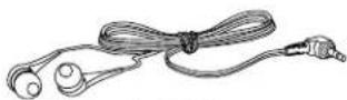
EB4
Earbuds
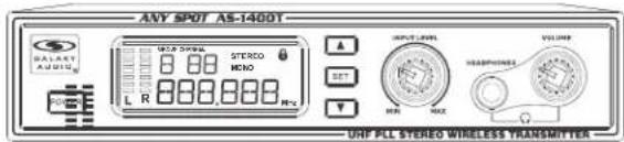
AS-1400T Transmitter
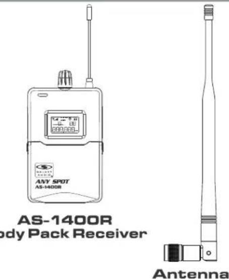
AS-1400R Body Pack Receiver
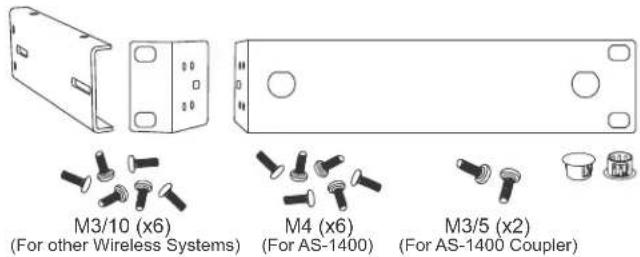
MREWD Single/Dual Rack Kit
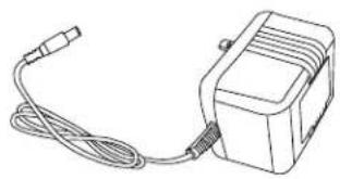
PS-13.5-.35.5 Power Supply
Quick Start Guide
Attaching the Rack Ears
What You Need for Rack Mounting:
(Not Included)
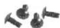
- Rack Screws 10/32 x 0.75", Phillips Truss Head Screws
-
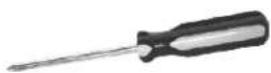
2 Phillips Head Screwdriver
For Racking a Single Unit:
- Attach the long and short rack ears to either side of choice using the provided screws.
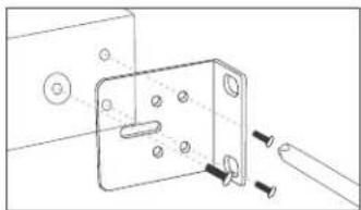
For Racking a Two Units:
- Attach the short rack ear to either side of choice using the provided screws.
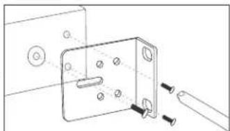
- Align the unit up evenly. Turn the screw but leave room to adjust. Once all three screws are in place, tighten securely.

- After removing the screw from the side of the unit, attach the coupler half to the other side using the provided screws.
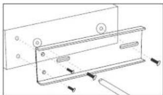
- Align the two units so that the couplers overlap and the holes align. Using the provided coupler screws (M3/5), screw the couplers together securely.
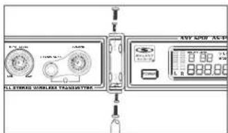
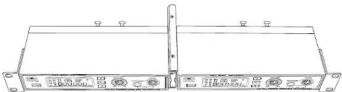
AS-1400 Wireless In-Ear Monitor System Transmitter
Transmitter Features:
Front Panel
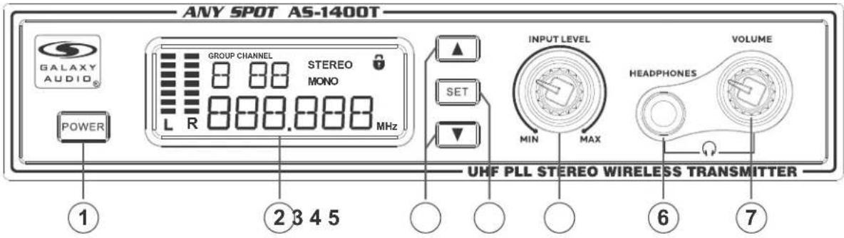
①- Power Switch: ON/OFF for transmitter
② - LCD Screen: Displays information (for Group, Channel, Frequencies, L/R Input AF, and more)
③- Function Buttons: Up ▲and Down ▼Buttons
④- Function Button: Set Button
⑤ L/R Input Level
⑥- 1/4" 6.35 mm Stereo Headphone Jack
⑦- Headphone Output Volume Control
Rear Panel
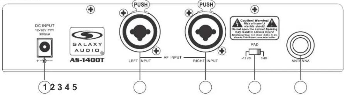
① DC Adapter Jack: 12-18V 350mA
②- Left Input XLR/1/4" Combo
③- Right Input XLR/1/4" Combo
④ - PAD Switch: Use to reduce input gain. To cut gain, set to -12dB. To leave gain unaffected, set to 0dB
⑤ BNC Antenna Jack
AS-1400 Wireless In-Ear Monitor Body Pack Receiver
Body Pack Receiver Features:

①- Stereo Headphone Jack 1/8" (3.5 mm)
②- Audio Output Control and On/Off Switch
③ Antenna
④ Low Battery Indicator: LED will flash red when battery is low.
⑤ RF Signal LED: Lights up green when RF Signal is Received.
⑥ LCD Screen: Displays information (for Group, Channel, Frequencies, L/R Input AF, and more)
⑦- ESC Button: Exits the menu setup
⑧- UP Button
⑨- SET Button
⑩ - DOWN Button
⑪ - Battery Compartment: Insert batteries here. (Two AA 1.5VDC Alkaline recommended)
Wearing the Body Pack Receiver
Belt Clip: For best results, clip the receiver onto a belt by pushing the receiver down onto the belt as far as possible.
Changing Batteries
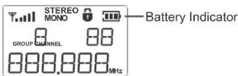
Expected life for two AA Alkaline batteries is approximately 5 hours. When the LCD battery indicator is flashing, the batteries should be replaced. The batteries should be changed immediately. (see below)
System Setup
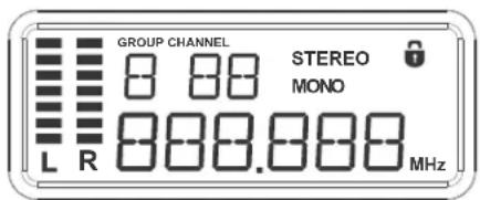
Fig. 1
Programming the Transmitter
1. Power On:
Hold the power button for 3 seconds to power on the transmitter. Display will light up. Hold for another 3 seconds to turn off.
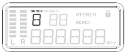
Fig. 2a
2. Frequency Group and Channel Selection:
Press the "SET" button. The display will flash "GROUP". Press ▲ or ▼ to select a suitable frequency group number as shown in Fig. 2a. Press "SET" again. The display will flash "CHANNEL". Press ▲ or ▼ to select a suitable channel as shown in Fig 2b.
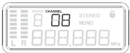
Fig. 2b
Note: When using multiple systems, for optimum results, set all of the systems to the same group number and select a different channel number for each system in that group.
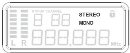
Fig. 3
3. Stereo/Mono Input Mode Selection:
Press the "SET" button 3 times, the "STEREO" will flash. Press ▲ or ▼ button to select Stereo or Mono, then press set again to set the selected mode as shown in Fig. 3.
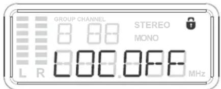
Fig. 4
4. Locking Control Selection:
Press the "SET" button 4 times, the "☐" will light up. Press ▲ or ▼ button to select Lock or Unlock status as shown in Fig. 4.
System Setup
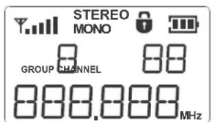
Fig. 1
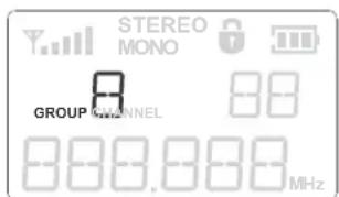
Fig. 2a
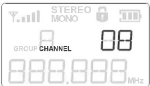
Fig. 2b
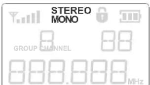
Fig. 3
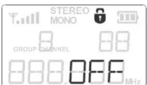
Fig. 4
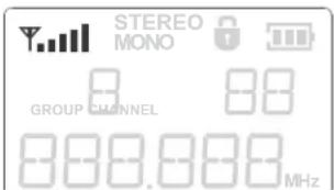
Fig. 5
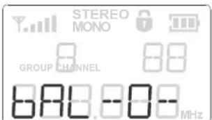
Fig. 6
Programming the Body Pack Receiver
1. Power On:
Turn the Body Pack on by turning the volume control clock-wise. The LCD display will light up as shown in Fig 1.
2. Frequency Group and Channel Selection:
Press the "SET" button. The display will flash "GROUP". Press ▲ or ▼ to select a suitable frequency group number as shown in Fig. 2a. Press "SET" again. The display will flash "CHANNEL". Press ▲ or ▼ to select a suitable channel as shown in Fig 2b. Make certain that the transmitter and receiver are on the same frequency.
Note: When using multiple systems, for optimum results, set all of the systems to the same group number and select a different channel number for each system in that group.
3. Stereo/Mono Select:
Press the "SET" button 3 times. The stereo/mono display will flash. Press the ▲ or ▼ buttons to select desired mode as shown in Fig. 3.
4. Locking Control Selection:
Press the "SET" button 4 times until "💡" lights up. Press ▲ or ▼ button to select Lock or Unlock status as shown in Fig. 4.
5. RF Signal Indication:
The receiver has 5 levels of RF signal indication as shown in Fig. 5.
6. Pan Control:
Use the arrow keys to adjust the left/right balance as shown in Fig. 6.
▲ balance to left
▼ balance to right
Stereo Mode: The transmitter and receiver should both be switched into stereo.
STEREO MODE
![graph TD A["Head"] --> B["AS-1400R"] C["Head"] --> D["AS-1400R"] E["Head"] --> F["AS-1400R"] G["Head"] --> H["AS-1400R"] I["AS-1400T"] --> J["MIXER"] K["AS-1400T"] --> L["MIXER"] M["AS-1400T"] --> N["MIXER"] O["AS-1400T"] --> P["MIXER"] Q["AS-1400T"] --> R["MIXER"] S["AS-1400T"] --> T["MIXER"] U["AS…](/content/2026/05/812108/images/2dbc1e705dcb923bb717897d53c92cc77a299ad0d45f0d7825f4613e853f4a2a.jpg)
Mono Mode: Use the Left input, switch the transmitter to mono, the receiver can remain switched to stereo as the transmitter is sending a mono mix to both ears.
MONO MODE
![graph TD A["head with MIX 3"] --> B["AS-1400R"] C["head with MIX 2"] --> D["AS-1400R"] E["head with MIX 1"] --> F["AS-1400R"] B --> G["AS-1400T"] D --> H["AS-1400T"] F --> I["AS-1400T"] G --> J["MIXER"] H --> J I --> J style A fill:#f9f,stroke:#333 style C fill:#f9f,stroke:#333 style E fill:#f9f,str…](/content/2026/05/812108/images/c237515fd2798658a6e49c9bb657e456a7b1d2911195a8fef01913e151742a65.jpg)
Mixed Mono Mode: When you are sending two mixes to the transmitter, the transmitter should be set to stereo and the receiver should be set to mono. The pan control on the receiver then becomes the balance control between the two mixes and both mixes are in both ears.
MIXED MONO MODE
![graph TD A["Pan Left for more band"] --> B["AS-1400R"] C["Pan Right for more solo"] --> D["AS-1400R"] B --> E["AS-1400T"] D --> E E --> F["MIXER"] G["BAND MIX"] --> E H["SOLO MIXES"] --> E I["Head Signal"] --> J["Head Signal"] K["Signal Signal"] --> L["Signal Signal"]](/content/2026/05/812108/images/2bc5d74dcee21ef55c88ceb1421e16a9044eef9c97943de0ddfd2168fea40cfa.jpg)
Specifications
System
Band: UHF
Frequencies: 275 Selectable Frequencies
Frequency Range: CODE M 516-558MHz
Transmitter Output Level: 30 mW
Operating Range: Under Typical Conditions 300' (92m) (in open space)
Note: actual range depends on RF signal absorption,
reflection, interference, and battery characteristics.
Audio Frequency Response: ±3 dB 40 Hz-16 KHz
Total Harmonic Distortion: < 0.4% @ 1 KHz
Signal to Noise: >105dB
Maximum Deviation Range: ±68 KHz
Dynamic Range: >90 dB A-weighted
Operating Temperature: Range 14°F to 122°F (-10 C° to +50 C°)
Note: battery characteristics may limit this range
Band Width: 42MHz
Transmitter
Main Frame Size: EIA STANDARD 1/2 U
Modulation Mode: FM stereo modulation
RF Output: 30 mW
Max Audio Input Level: +6 dBV
Gain Adjustment Range: 33dB
Audio Input: Line Level x2, XLR/ 1/4" Combo Jack
XLR input: Balanced
Pin 1: Ground (cable shield)
Pin 2: Audio +
Pin 3: Audio
Audio Output: 1/4" Headphone Out
Dimensions: 1.7" x 8.2" x 7.09" (44 x 209 x 180 mm)(HxWxD)
Weight: 2.34 lbs (1.06 kg)
Power Requirements: 12-18 V DC at 300 mA supplied by external power supply
GALAXY AUDIO
Frequency Page

http://www.galaxyaudio.com/support/schematica-and-frequency-charts
Please click or scan the QR for the most current frequency information.
Receiver
Audio Output Level: 100 mW
Sensitivity: 6 dBμV, S/N>80 dB
Stereo Separation: 45 dB (at 1 KHz)
Output Connector: 1/8"(3.5 mm) stereo earphone connector
Dimensions: 4.33" x 2.56" x 0.87" (110 x 65 x 22 mm)(HxWxD)
Weight: 0.32 lbs (0.145 kg)
Power Requirements: 2 (AA) size alkaline or rechargeable batteries
Battery Life: About 7 hours
Parts and Accessories
Many of these parts and accessories may be found and purchased from the Galaxy Audio website in the Galaxy Store (www.galaxyaudio.com/parts-and-accessories).


EXTBNC - BNC Cable for front mounting the antennas on the AS-1400. For lengths available: 18", 25', 50', 100'
CN-BNCPM - BNC Connector for front mounting the antennas on the AS-1400.
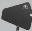
ANT-PDL - Directional antenna used to decrease interference to other equipment. Frequency range 500-900MHz The UHF wide-band (500-900 MHz) directional LPDA (log periodic dipole array) antenna reduces outside interference while providing increased send/receive signal range. Each antenna paddle is matched to 50 ohms impedance with a low-loss BNC connector; 7dBi gain. For permanent or temporary installation; mounts to 5/8"-27 threads.
AS-ANTBNC - Replacement BNC Antenna for use with Galaxy Audio Wireless Personal Monitors. (Part number will vary based on the Frequency Code of specific unit)

CLIP1400R - Replacement Belt Clip for AS-1400 Body Pack

BATTCVR1400R - Replacement Battery Cover for AS-1400 Body Pack.
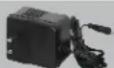
PS-13.5-.35.5 - 600mA Replacement Power Supply for AS-900, AS-1100, AS-1400, VES, VSC, EDX, ECM, PSE, & DHX.
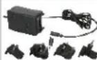
AS-UA12-14.5 - 1000mA Universal Power Supply for Replacement Power Supply for AS-900, AS-1100, AS1400, AS-1800, VES, VSC, EDX, ECM, PSE, DHX, DHXR4, & CTS. Includes adapters for most other countries.
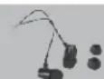
EB4 - Ear buds which come standard with our Wireless Personal Monitor Systems with 1/8" - 3.5mm Jack.
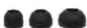
EB4S - Replacement Sleeves for EB4 Ear Buds. 5 pair in each pack. Available in Small, Medium, or Large.
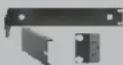
MREWD - Replacement Single/Dual Rack Kit for AS-900, AS-1100, & AS-1400
Wireless Tips
Maintain line of sight between the transmitter and receiver antennas.
Do not have walls, metal objects, large crowds, etc. blocking the line of sight between the transmitter and receiver.
Antennas on the stationary equipment should be kept several feet above the ground.
Antennas can be mounted on stands or walls using brackets such as the ANT-LB.
On body pack receivers/transmitters, avoid putting them in your pocket, and/or folding the antenna under the pack. The antenna should hang freely and openly.
Keep the distance between transmitters and receivers as short as possible.
If distances above 20-30' are unavoidable, directional antennas such as the ANT-PDL can improve reception by rejecting signals outside their pickup angle.
Find out what TV stations are broadcasting in your area and avoid the channels they are on.
This information is available from many sources on line, such as www.tvfool.com.
If your receiver is showing that it is receiving RF when your transmitter is turned off, you need to move to another frequency.
If you are using several systems, you can contact service@galaxyaudio.com for assistance in frequency coordination.
Make certain you are using fresh batteries, rechargeable batteries may be used, but they discharge at a much faster rate than alkaline.

WARRANTY Information can be viewed online at http://www.galaxyaudio.com/support/warranty

www.galaxyaudio.com/support/warranty
AS-1400
USER'S MANUAL
Specifications in this manual are subject to change without notice. For the most up to date manual and information visit www.galaxyaudio.com.
1-800-369-7768
www.galaxyaudio.com
© Copyright Galaxy Audio 2017
- INTRODUCTION
- TRANSMITTER INSTALLATION AND CONNECTIONS
- INSTALLATION
- CONNECTIONS
- USING THIS SYSTEM AT EXCESSIVE VOLUMES CAN CAUSE PERMANENT HEARING DAMAGE. USE AS LOW A VOLUME AS POSSIBLE
- WARNING
- IMPORTANT SAFETY INSTRUCTIONS
- LICENSING INFORMATION
- THIS RADIO EQUIPMENT IS INTENDED FOR USE IN PROFESSIONAL ENTERTAINMENT AND SIMILAR APPLICATIONS
- NOTE: THIS EQUIPMENT MAY BE CAPABLE OF OPERATING ON SOME FREQUENCIES NOT AUTHORIZED IN YOUR REGION. PLEASE CONTACT YOUR NATIONAL AUTHORITY TO OBTAIN INFORMATION ON AUTHORIZED FREQUENCIES FOR WIRELESS MICROPHONE PRODUCTS IN YOUR REGION
- SYSTEM COMPONENTS
- ATTACHING THE RACK EARS
- 2 PHILLIPS HEAD SCREWDRIVER
- FOR RACKING A SINGLE UNIT
- FOR RACKING A TWO UNITS
- AS-1400 WIRELESS IN-EAR MONITOR SYSTEM TRANSMITTER
- TRANSMITTER FEATURES
- AS-1400 WIRELESS IN-EAR MONITOR BODY PACK RECEIVER
- BODY PACK RECEIVER FEATURES
- WEARING THE BODY PACK RECEIVER
- CHANGING BATTERIES
- SYSTEM SETUP
- PROGRAMMING THE TRANSMITTER
- POWER ON
- FREQUENCY GROUP AND CHANNEL SELECTION
- STEREO/MONO INPUT MODE SELECTION
- LOCKING CONTROL SELECTION
- PROGRAMMING THE BODY PACK RECEIVER
- STEREO/MONO SELECT
- RF SIGNAL INDICATION
- PAN CONTROL
- SPECIFICATIONS
- SYSTEM
- TRANSMITTER
- RECEIVER
- PARTS AND ACCESSORIES
- WIRELESS TIPS
- WARRANTY INFORMATION CAN BE VIEWED ONLINE AT HTTP://WWW.GALAXYAUDIO.COM/SUPPORT/WARRANTY
- AS-1400
- USER'S MANUAL
Brand : Galaxy Audio
Model : AS-1400
Category : Earphones