
078493 - Motion detector LEGRAND - Free user manual and instructions
Find the device manual for free 078493 LEGRAND in PDF.


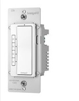
| Product Type | KNX PIR Motion Detector (flush-mounted) |
| Model Numbers | Céliane 0 675 77, Mosaic 0 784 93, Artéor 5 740 37 (White), 5 740 79 (Magnesium) |
| Power Supply | KNX bus, 29 V DC |
| Bus Current Consumption | 16 mA (PIR) |
| Detection Technology | Passive Infrared (PIR) |
| Detection Angle | 180° |
| Motion Detection Range (max) | 12 m (at very high sensitivity) |
| Presence Detection Range (max) | 5 m (at very high sensitivity) |
| Daylight Measurement Range | 5 to 1275 lux |
| Time Delay Settings | 5 s to 17 h 59 min 59 s |
| Operating Temperature | -5°C to +45°C |
| Storage Temperature | -25°C to +70°C |
| Ingress Protection | IP20 (alone), IP41 (assembled) |
| Impact Resistance | IK04 |
| Mounting | Flush-mounted in wiring device boxes |
| Functions | Automatic/manual switching/dimming, constant daylight regulation, master/slave configuration, virtual keycard, scene control |
| Configuration | Via ETS (v3+) or IR commissioning tool (ref. 088230/BMSO4001) |
| Pushbutton | Integrated pushbutton for local control |
| Maintenance | Clean with a cloth; avoid acetone, tar removers, trichloroethylene |
| Standards | IEC 60 669.2.1, KNX, CE |
Frequently Asked Questions - 078493 LEGRAND
User questions about 078493 LEGRAND
0 question about this device. Answer the ones you know or ask your own.
Ask a new question about this device
Download the instructions for your Motion detector in PDF format for free! Find your manual 078493 - LEGRAND and take your electronic device back in hand. On this page are published all the documents necessary for the use of your device. 078493 by LEGRAND.
USER MANUAL 078493 LEGRAND
3.1 Electrical features 2
3.2 Climatic features 2
3.3 Mechanical features 2
■ 4. Dimensions ....2
■ 5. Connection....2
■ 6. Removal ....2
■ 7. Installation....3
7.1 Sensor positioning .... 3
7.2 Recommended light exposure 3
■ 8. Operation....3
■ 9. Settings....4
9.1 Detection parameters 4
9.2 Lighting parameters....4
9.3 Other parameters 4
9.4 Modifying the parameters using the configuration tools....4
■ 10. Performance .... 4
10.1 PIR Performance - Motion detection 4
10.2 PIR Performance - Presence detection....5
■ 11. Standards and approvals....5
■ 12. Maintenance....5
■ 13. Communication objects....5
13.1 List of objects ....5
13.2 General parameters 6
13.2.1 Main function - Master: Light level only 6
13.2.2 Main function - Master: Detection only 10
13.2.3 Main function - Master: Light level & Detection 12
13.2.4 Slave: Detection only 20
13.3 Load....21
13.3.1 Use dimming load 21
13.3.2 Use expert parameters....22
13.3.3 Standby time base (function only available in Master mode: detection and Master: Light level & Detection) 23
13.3.4 Use second load....25
13.4 Light level config....26
13.4.1 Use external daylight cell 26
13.5 Detection config....28
13.5.1 Send Condition....29
13.6 Auxiliary output....30
13.6.1 None....30
13.6.2 Switching 30
13.6.3 Scaled values....31
13.6.4 HVAC Mode 32
13.6.5 Scene 33
13.6.6 2 bytes value .... 34
13.7 Advanced....35
13.7.1 Sensitivity (only available for Master: Detection Only, Master: Light level & Detection and Slave: Detection Only modes) 35
13.7.2 System detection (only available for Master: Detection Only, Master: Light level & Detection and Slave: Detection Only modes) ..... 35
13.7.3 Additional object for expert mode 36
13.8 Virtual Keycard 37
13.8.1 Use Virtual Keycard .... 37
13.8.2 Virtual keycard function operating diagram .....41
13.9 Commissioning Tool....42
13.10 Pushbutton....43
13.10.1 Pushbutton function 43
■ 14. Application's examples ....46
14.1 Mode Auto ON/OFF - Load ON/OFF 46
14.2 Mode Auto ON/OFF - Dimming load....46
14.3 Mode Manual ON/Auto OFF - Load ON/OFF....46
14.4 Mode Manual ON/AutoOFF - Dimming load 47
14.5 Master/Slave detection....47
1. USE
The KNX wiring devices sensors are passive infrared devices (PIR) suitable to detect motion and measure the daylight level. They can be installed directly on wiring devices boxes according to the specific wiring devices series They are suitable for indoor passage areas like corridors, bathrooms, technical rooms...
Through its application program it is possible to configure all the working parameters such as daylight threshold, time delay, operating modes, technology sensibility... and it is possible to configure the following functions:
- Switching/dimming: auotmatically or manually if associated with a control device
- Define a minimum/maximum dimming level
- Customize the dimming pace
- Trigger scenarios based on: presence/absence
- Work in master/slave configuration
- Define a daylight level to be maintained until presence is detected
- Manage more than one output with the same commands
All the KNX witing devices sensor already embed a push button
All the working parameters are configurable via ETS but is also possible to modify the main operating parameters (daylight threshold, time delay, technology sensibility...) via commissioning tool ref. 088230/BMSO4001.
- RANGE
| Description Catalogue number | ||
| Céliane - KNX PIRFlush mounted sensor 180° | 0 675 77 | |
| Mosaic - KNX PIRFlush mounted sensor 180° | 0 784 93 | |
 | Artéor - KNX PIRFlush mounted sensor 180° - White | 5 740 37 |
| Artéor - KNX PIRFlush mounted sensor 180° - Magnesium | 5 740 79 | |
3. TECHNICAL FEATURES
■ 3.1 Electrical features
- KNX BUS power supply: 29 =
- KNX BUS absorption: 16 mA (PIR)
- KNX connector (red/black): terminal capacity 4x (∅ 0,6 à 0,8 mm)
■ 3.2 Climatic features
- Environmental operating temperature: -5°C to +45°C
- Storage temperature: -25°C to +70°C
■ 3.3 Mechanical features
- Impact resistance: IK04
- Penetration by solid and liquid matter: IP20 (alone) IP41 (assembled product)

4. DIMENSIONS
067577

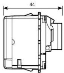
0 784 93 - 5 740 37/79


natural_image
Technical line drawing of a rectangular mechanical component with dimension标注 (no text or symbols)5. CONNECTION
KNX red/black connector
| 4x(∅0,6mm<∅0,8mm) |

- REMOVAL

7. INSTALLATION
■ 7.1 Sensor positioning
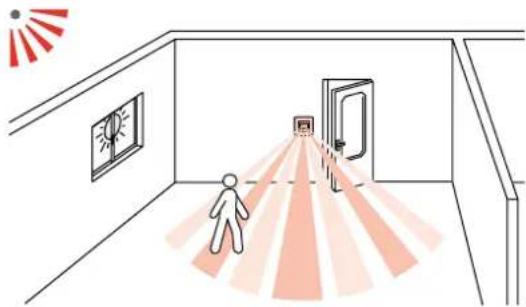
natural_image
Illustration of a person walking toward a doorway with radiating light beams, no text or symbols present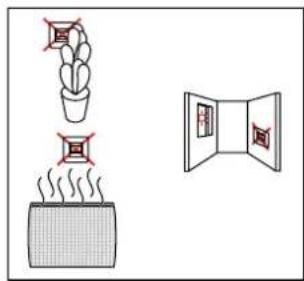
■ 7.2 Recommended light exposure
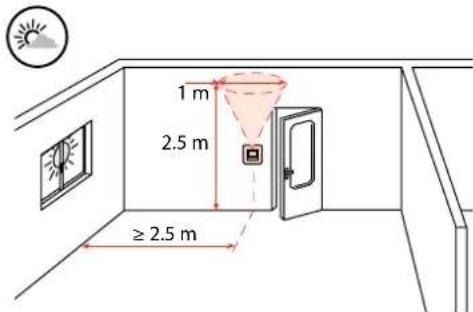
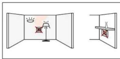
natural_image
Simple line drawing of a room with a lamp and wall-mounted shelf, no text or symbols present8. OPERATION
The KNX sensors offer many functions, on follows a summary of them (see section "Communication objects" for details):
Functions:
Automatic or manual switching/dimming with constant daylight regulation
Possibility to control a second lighting level as a % of the main one maintaining a positive or negative offset.
Coupling several detectors: It is possible to set the sensors in Master or slave configuration in order to cover a larger area with a synchronized presence detection.
Sending message on presence / absence: Upon presence/absence can be sent an additional command: switching command, values, scene...
Warning of end detection: After the time delay, the light can be configured to assume a standby level (for a standby time interval) as to warn of the imminent extinction.
Presence and brightness level Information is available on the bus: Values available for a supervision system.
Daylight setpoint and time delay modifiable by bus: Values which can be modified by a supervision system.
Partial on/Group off Mode:
It is possible to turn ON just a subset of lights but at the end of time delay turn OFF all the lights. Classroom example: Room Lighting: automatic switch ON; Board Lighting: manual control.
On end detection, total extinction, room and board.
Virtual Keycard: Especially thought for hotels, the combination of presence sensors, door contacts and other informations (e.g. other detectors, push buttons...) allow determining the presence in the room and empower some circuits in the room, launch scenarios or any other kind of logics.
The functions is triggered by the "door contact" event which launch the so called "Virtual keycard time delay", a time offset in which the sensor tries to understand if the room is occupied or not on the basis of some informations: sensor detection, window contact events, push buttons event. Once the result of the function is "occupied" it permains until there is another "Door contact event" which trigger another "Virtual keycard time delay" to understand the room status and eventually turn OFF the lights, launch an absence scenario or launch any other logic related to vacancy event.
The product global configuration is made via ETS (version 3 or upper) and it is also possible to modify the main operating parameters via commissioning tool 088230/BMSO4001 (see following section for further details)
9. SETTINGS
Following the main operating parameters modifiable via commissioning tool 088230/BMSO4001.
■ 9.1 Detection parameters
| Sensor parameter Default value | Possible values Configuration tools 088230/ BMSO4001 | ||
| Time delay | 15 min | 5 s - 17 H59 min 59 s | |
| Sensitivity | PIR (Very high) | Low, Medium, High, Very high | |
| Detection system | Initial PIR No modifiable | ||
| Maintain PIR No modifiable | |||
Time delay: It is the time interval between the moment in which a sensor does not detect motion/presence and the deactivation of the load.
The time period re-starts whenever the sensor detects motion/presence
Sensitivity: It is the detection technology sensitivity.
Detection system:
It is the set of technologies used for detection
Initial detection: it is the set of technologies used for the first detection
Maintain: it is the set of technologies used after the first detection
■ 9.2 Lighting parameters
| Sensor parameter Default value | Possible values Configuration tools 088230/ BMSO4001 |
| Daylight setpoint 300 lux 5 - 1275 lux |
Daylight setpoint: it is the lighting level under which the sensor enables the load and over which the sensor disables the load.
Eye function: Value 0 (eye on configuration tool 088230/BMSO4001) this function allows to record in the sensor the actual general lighting level and use it as daylight setpoint.
■ 9.3 Other parameters
| Sensor parameter Default | value | Possible values Configuration tools088230/BMSO4001 | |
| Output | Standby delay(main load) | Disabled | Disabled/infinite/1 s - 1 h |
| Standby level(main load) | 10 % | 1 - 100 % | |
Standby level: it is the level, expressed in % of the daylight setpoint, at which the load is keep turned ON during the standby delay.
Standby delay: it is the time interval in which the load is kept turned ON at the standby level. It begins as soon as the sensor does not detect motion/presence
9. SETTINGS (continued)
■ 9.4 Modifying the parameters using the configuration tools

natural_image
Illustration of a hand holding a remote control device emitting red waves, next to a wall-mounted device (no text or symbols)• 088230/BMSO4001: Advanced configuration tool
When the sensor receives an IR command via a configuration tool, the LED blinks.
- Restore to factory settings:
1 ^st press: Short press on PROG, the LED flashes slowly.
2 ^nd press: Hold down PROG for 10 seconds until the LED flashes quickly.
10. PERFORMANCE
■ 0.1 PIR Performance - Motion detection
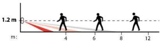
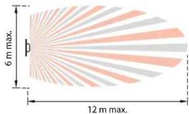
| Sensitivity | m |
| Low (25%) | 7 |
| Medium (50%) | 8 |
| High (75%) | 10 |
| Very high (100%) | 12 |
10. PERFORMANCE (continued)
■10.2 PIR Performance - Presence detection


| Sensitivity m | |
| Low (25%) 1 | |
| Medium (50%) 2 | |
| High (75%) 4 | |
| Very high (100%) 5 |
11. STANDARDS AND APPROVALS
- Complies with standard IEC 60 669.2.1
- Marking: KNX, CE
Note:
All technical information is available at

www.legrandoc.com
12. MAINTENANCE
Clean the surface with a cloth.
Do not use acetone, tar-removing cleaning agents or trichloroethylene.
Caution:
Always test before using other special cleaning products.
13. COMMUNICATION OBJECTS
■ 13.1 List of objects
Here are listed the communication objects active by default settings.
| No. | Object name | Function | Size Flags | ||
| 1 | Switching | Switching | 1.001 DP_On/Off | CT | |
Switching telegrams are sent via the group address linked to this object
| 2 | Switching Status | Switching Status | 1.001 DP_On/Off | CWTU |
Switching statuses are received via the group address linked to this object.
*If switching statuses are received but the Switching object has not been sent by the sensor, the regulation is stopped.
| 5 | In Occupancy | In Occupancy | 1.002 DP_Bool | CW |
In Occupancy statuses are received via the group address linked to this object. It will be used especially for connecting slave sensor and increase a detection zone (13.5 Master/slave detection).
True: The sensor reacts as if there is an internal detection
False: No reaction
| 6 | Occupancy status | Occupancy status | 1.002 DP_Bool | CRT |
Out Occupancy statuses are sent via the group address linked to this object True: When motion is detected
False: After vacancy time delay, or occupancy if vacancy is not used
| 8 | Out Lux | Out Lux | 9.004 DP_Lux | CRT |
Out Lux values are sent via the group address linked to this object. Send operations can be set in ETS (Cyclical, on change, on request).
| 16 | Switching group off | Switching group off | 1.001 DP_On/Off | CRT |
Switching group off statuses are sent via the group address linked to this object. On vacancy is sent an OFF via the group adress linked to this object.
| 20 | Out occupancy | Out occupancy | 1.002 DP_Bool | CT |
Out synchro Master-> Slave statuses are sent via the group address linked to this object
True: The maintain status is sent to the slave False: The initial status is sent to the slave
| 21 | Enable | Enable | 1.003 DP_Enable | CRW |
Enable telegrams are received via the group address linked to this object. They are used to lock (disable) or unlock (enable) the corresponding input.
13. COMMUNICATION OBJECTS (continued)
■13.2 General parameters
13.2.1 Main function - Master: Light level only
| Parameters Settings | |
| Main function Master: Light level only | Master: Detection onlyMaster: Light level & detectionSlave: Detection only |
Only load and light level can be configured in the associated page, and regulation is active
13.2.1.1 Mode
• Auto on/Auto off mode
Comes on automatically: - At the detection of a presence if there is an insufficient natural level of light. Turns off automatically: - If no presence is detected and at the end of the time delay set. - Or if there is a sufficient natural level of light (activated setting). Any new detection causes an automatic switch on if there is insufficient light.
- Walkthrough
- If there is no presence detected in the 3 minutes following an initial detection, the product will cut off after 3 minutes.
- If a new presence is detected in the 3 minutes following the initial detection, the device will cut off at the end of the time delay set.
Manual on/Auto off mode: Comes on via a manual switch, automatic switch off: - Where no presence is detected and at the end of the time delay set. Following switch-off any new detection within a 30 second period will cause the device to be switched on automatically.
After 30 seconds the device is switched on via a manual switch.

| Parameters Settings | |
| Reaction speed Very Low | LowNormalFastVery Fast |
| This parameter determines the speed reaction of the régulation in dimming or switching | |
| Start regulation with power on Yes | No |
| This parameter determines if regulation is started with power on | |
System behaviour:
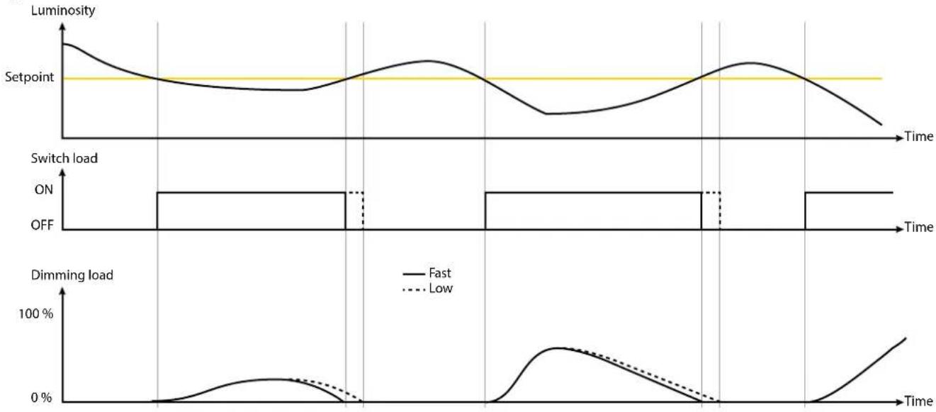
Technical data sheet: S000089366EN-3 Updated: 24/06/2019 Created: 26/05/2015
legrand
13. COMMUNICATION OBJECTS (continued)
■ 13.2 General parameters (continued)
13.2.1 Main function - Master: Light level only (continued)
13.2.1.2 Mode: Manual ON/Auto OFF

| No. | Object name Function | Size Flags | ||
| 13 | Synchro regulation | Synchro regulation | 1.010 DP_Start/stop | CW |
| In Lux values are received via the group address linked to this object.Start and stop can be configured in ETS.Message start/stop régulation is received to this object. | ||||
| 14 | Regulation status | Regulation status | 1.010 DP_Start/stop | CRT |
| Regulation statuses are sent via the group address linked to this object | ||||
System behaviour:

line
| Time | Luminosity | Switch Load ON | Switch Load OFF | Power (Dimming Load) | |------|------------|----------------|-----------------|------------------------| | Start | High | Yes | No | 0% | | Command Start | Low | Yes | No | 100% | | Command Stop+OFF | Low | Yes | No | 100% | | Command Start | High | Yes | No | 0% |13. COMMUNICATION OBJECTS (continued)
■ 13.2 General parameters (continued)
13.2.1 Main function - Master: Light level only (continued)
13.2.1.2 Mode: Manual ON/Auto OFF (continued)
Parameters Settings
| Action on "Synchro regulation" object on start Start regulation |
ON + Start regulation
Stop regulation
Stop regulation + ON
Stop regulation + OFF
No reaction
This parameter determines the regulation reaction when Start received.
Start regulation: Regulation is run with no action on load
ON + Start regulation: Regulation is run with ON action on load
Stop regulation: Regulation is stopped with no action on load
Stop regulation + ON: Regulation is stopped with ON action on load
Stop regulation + OFF: Regulation is stopped with OFF action on load
No reaction: No reaction
Action on "Synchro regulation" object on stop Start regulation
| ON + Start regulation | |
| Stop regulation | |
| Stop regulation + ON | |
| Stop regulation + OFF | |
| No reaction |
ON + Start regulation
This parameter determines the regulation reaction when Stop received.
Start regulation: Regulation is run with no action on load
ON + Start regulation: Regulation is run with ON action on load
Stop regulation: Regulation is stopped with no action on load
Stop regulation + ON: Regulation is stopped with ON action on load
Stop regulation + OFF: Regulation is stopped with OFF action on load
No reaction: No reaction
Use scene No
| Yes |
No: In scene regulation cannot be used, no accessible communication objects.
- Use scene - Yes
Use scene
Scene A number (D: not used)
Scene A action
Scene B number (0: not used)
Scene B action
Scene C number (0: not used)
Scene C action
Scene D number (0: not used)
Scene D action
Scene E number (0: not used)
Scene E action











13. COMMUNICATION OBJECTS (continued)
■ 13.2 General parameters (continued)
13.2.1 Main function - Master: Light level only (continued)
13.2.1.2 Mode: Manual ON/Auto OFF (continued)
- Use scene – Yes (continued)
When use scene is yes: this object communication is available.
| No. | Object name Function | Size Flags | ||
| 12 In | scene_regulation | In_scene_regulation | 17.001 DP_Scene_number | CW |
8-bit auxiliary telegrams are received via the group address linked to this object. On scene telegram you can start/stop regulation with on/off (mode manuel On/Auto Off).
| Parameters Settings | |
| Scene A to E number | 0-64 |
| This parameter determines which scene (1..64) is to be recalled.If value "0" is set, no scene will be recalled | |
| Scene A to E action | Start regulationON + Start regulationStop regulationStop regulation + ONStop regulation + OFFNo reaction |
| This parameter determines the regulation reaction when scene number is received.Start regulation: Regulation is run with no action on loadON + Start regulation: Regulation is run with ON action on loadStop regulation: Regulation is stopped with no action on loadStop regulation + ON: Regulation is stopped with ON action on loadStop regulation + OFF: Regulation is stopped with OFF action on loadNo reaction: No reaction | |
13. COMMUNICATION OBJECTS (continued)
■ 13.2 General parameters (continued)
13.2.2 Main function - Master: Detection only
| Parameters Settings | |
| Main function Master: Light level only | Master: Detection onlyMaster: Light level & detectionSlave: Detection only |
Load, detection, early warning, AuxOutput and Advanced config can be configured in the various associated pages, and regulation is not active.
13.2.2.1 Mode: Auto ON/OFF

| Parameters Settings | |
| Active regulation Yes | No |
No: No regulation possible
System behaviour:

13. COMMUNICATION OBJECTS (continued)
■ 13.2 General parameters (continued)
13.2.2 Main function - Master: Detection only (continued)
13.2.2.2 Mode: Manual ON/Auto OFF
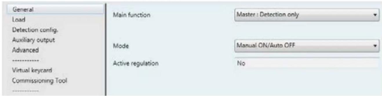
| No. | Object name Function | Size Flags | ||
| 13 | Synchro on/off | Synchro on/off | 1.010 DP_Start/stop | CW |
Synchro on/off statuses are received via the group address linked to this object.
| Parameters Settings | |
| Active regulation Yes | No |
No: No regulation possible
System behaviour:
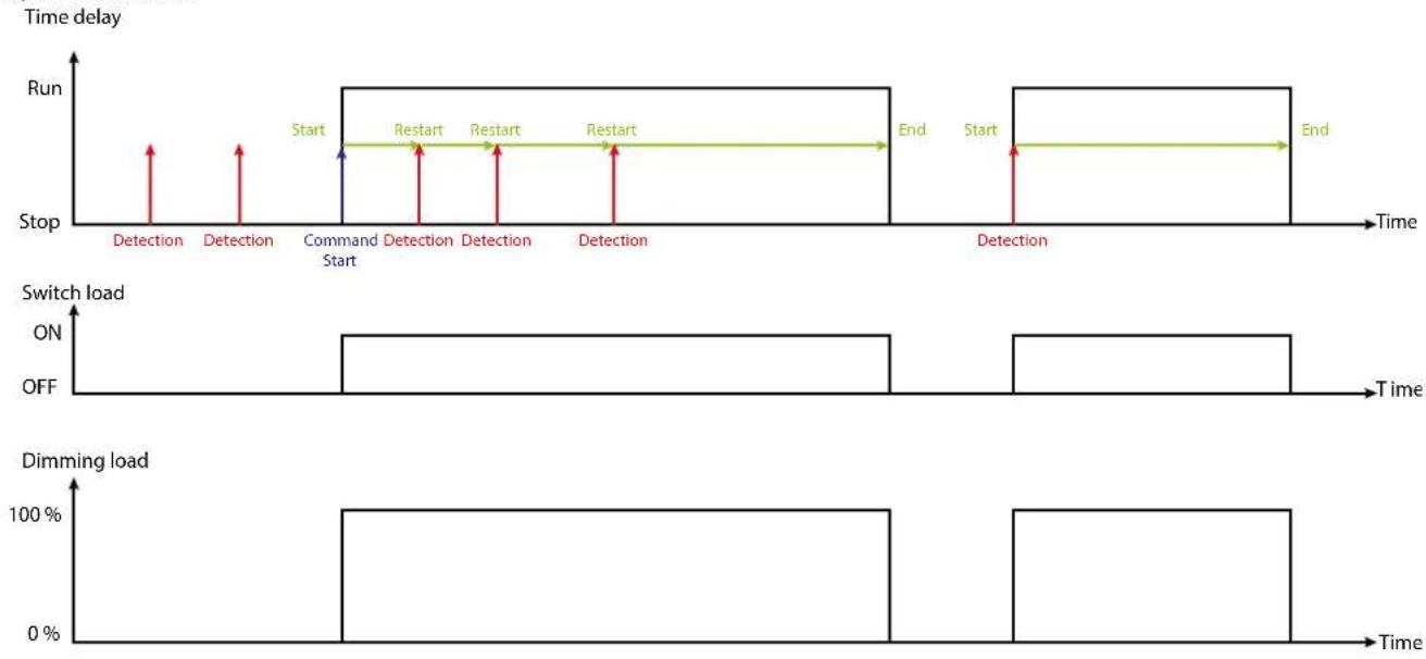
line
| Event Type | Start/End | Run | Time | |------------|-----------|-----|------| | Start | Start | Stop | 0 | | Restart | Restart | Command Start | 0 | | End | End | Detection | 0 | | Switch Load | ON | OFF | 0 | | Dimming Load | 100% | Off | 0 |13. COMMUNICATION OBJECTS (continued)
■ 13.2 General parameters (continued)
13.2.3 Main function - Master: Light level & Detection
| Parameters Settings | |
| Main function Master: Light level only | Master: Detection onlyMaster: Light level & detectionSlave: Detection only |
Load, light level, detection, early warning, AuxOutput and Advanced config can be configured in the various associated pages.
13.2.3.1 Mode: Auto ON/OFF
The system runs automatically.

| Parameters Settings | |
| Active regulation Yes | No |
No: No regulation possible
Yes: The cell in the sensor will switch ON/OFF or dim its associated loads according to variations in the natural light
System behaviour:
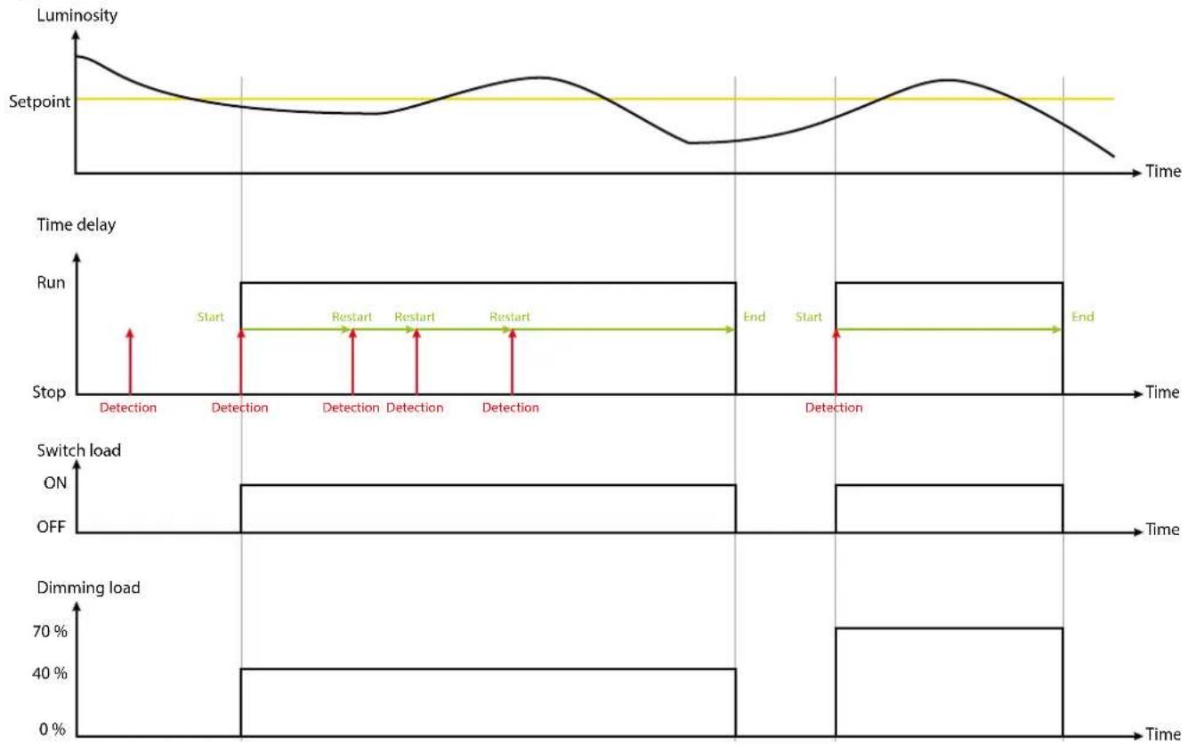
line
| Time | Luminosity | Time delay | Switch load | Dimming load | |------|------------|------------|-------------|--------------| | Start | 1000 | Yes | ON | 40% | | Restart | 1000 | Yes | ON | 40% | | End | 1000 | Yes | ON | 70% |Technical data sheet: S000089366EN-3 Updated: 24/06/2019 Created: 26/05/2015
13. COMMUNICATION OBJECTS (continued)
■ 13.2 General parameters (continued)
13.2.3 Main function - Master: Light level & Detection (continued)
13.2.3.1 Mode: Auto ON/OFF(continued)
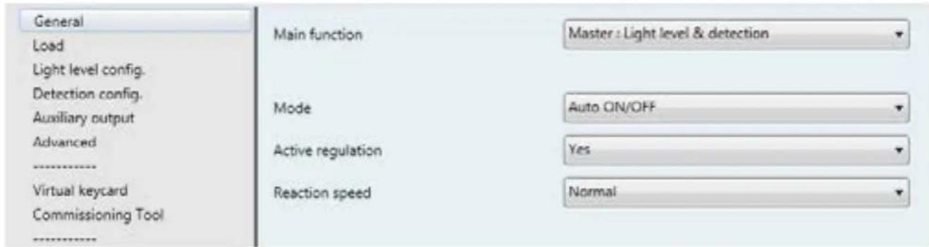
| Parameters Settings | |
| Active regulation Yes | No |
No: No regulation possible
Yes: The cell in the sensor will switch ON/OFF or dim its associated loads according to variations in the natural light
| Reaction speed Very Low | LowNormalFastVery Fast |
This parameter determines the speed reaction of the regulation in dimming or switching
When active régulation is yes: this object communication is available.
| No. | Object name Function | Size Flags | ||
| 10 In | _Detection_enable | In_Detection_enable | 1.003 DP_Enable | CRW |
In detection enable statuses are received via the group address linked to this object.
Enable: The sensor is in Light level & detection mode
Disable: The sensor is in light level only mode
Used to enable/disable the DETECTION ONLY, by a control schedule for example.
13. COMMUNICATION OBJECTS (continued)
■ 13.2 General parameters (continued)
13.2.3 Main function - Master: Light level & Detection (continued)
13.2.3.1 Mode: Auto ON/OFF(continued)
System behaviour:

line
| Time | Luminosity | Run | Switch Load | Dimming Load | |------|------------|-----|-------------|--------------| | Start | Low | 0 | ON | 0% | | Restart | Medium | High| OFF | 100% | | End | High | Low | ON | 0% |13.2.3.2 Mode: AUTO Walkthrough

| Parameters | Settings |
| Active regulation | YesNo |
No: No regulation possible
Yes: The cell in the sensor will switch ON/OFF or dim its associated loads according to variations in the natural light
| Reaction speed | Very Low |
| Low | |
| Normal | |
| Fast | |
| Very Fast |
This parameter determines the speed reaction of the regulation in dimming or switching
13. COMMUNICATION OBJECTS (continued)
■ 13.2 General parameters (continued)
13.2.3 Main function - Master: Light level & Detection (continued)
13.2.3.3 Mode: Manual On/Auto Off
The system runs with manual operation.

| No. | Object name Function | Size Flags | ||
| 13 | Synchro on/off | Synchro on/off | 1.010 DP_Start/stop | CW |
| Synchro on/off statuses are received via the group address linked to this object | ||||
| Parameters Settings | |
| Active regulation Yes | No |
No: No regulation possible
Yes: The cell in the sensor will switch ON/OFF or dim its associated loads according to variations in the natural light
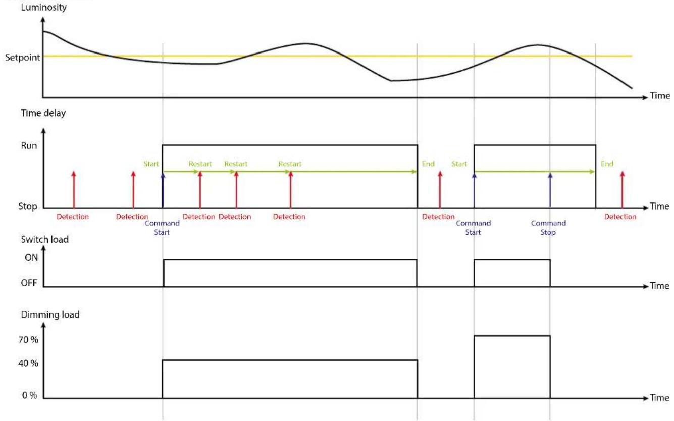
System behaviour:
line
| Time | Luminosity | Time delay | Switch load ON | Switch load OFF | Dimming load | |------|------------|------------|----------------|-----------------|--------------| | Start | Low | Yes | ON | Off | 40% | | Restart | High | Yes | ON | Off | 70% | | End | Low | Yes | ON | Off | 0% |13. COMMUNICATION OBJECTS (continued)
■ 13.2 General parameters (continued)
13.2.3 Main function - Master: Light level & Detection (continued)
13.2.3.3 Mode: Manual On/Auto Off (continued)

| Parameters Settings | |
| Active regulation Yes | No |
No: No regulation possible
Yes: The cell in the sensor will switch ON/OFF or dim its associated loads according to variations in the natural light
When active régulation is yes: this object communication is available.
| No. | Object name Function | Size Flags | ||
| 13 | Synchro regulation | Synchro regulation | 1.010 DP_Start/stop | CW |
| In Lux statuses are received via the group address linked to this object.Start and stop can be configured in ETS. | ||||
| 14 | Regulation status | Regulation status | 1.010 DP_Start/stop | CRT |
| Regulation statuses are sent via the group address linked to this object | ||||
13. COMMUNICATION OBJECTS (continued)
■ 13.2 General parameters (continued)
13.2.3 Main function - Master: Light level & Detection (continued)
13.2.3.3 Mode: Manual On/Auto Off (continued)
System behaviour:

13. COMMUNICATION OBJECTS (continued)
■ 13.2 General parameters (continued)
13.2.3 Main function - Master: Light level & Detection (continued)
13.2.3.3 Mode: Manual On/Auto Off (continued)
| Parameters Settings | |
| Reaction speed Very Low | LowNormalFastVery Fast |
| This parameter determines the speed reaction of the regulation in dimming or switching | |
| Action on “Synchro regulation” object on start Start regulation | ON + Start regulationStop regulationStop regulation + ONStop regulation + OFFNo reaction |
| This parameter determines the regulation reaction when Start received.Start regulation: Regulation is run with no action on loadON + Start regulation: Regulation is run with ON action on loadStop regulation: Regulation is stopped with no action on loadStop regulation + ON: Regulation is stopped with ON action on loadStop regulation + OFF: Regulation is stopped with OFF action on loadNo reaction: No reaction | |
| Action on “Synchro regulation” object on stop Start regulation | ON + Start regulationStop regulationStop regulation + ONStop regulation + OFFNo reaction |
| This parameter determines the regulation reaction when Stop received.Start regulation: Regulation is run with no action on loadON + Start regulation: Regulation is run with ON action on loadStop regulation: Regulation is stopped with no action on loadStop regulation + ON: Regulation is stopped with ON action on loadStop regulation + OFF: Regulation is stopped with OFF action on loadNo reaction: No reaction | |
| Use scene No | Yes |
| No: In scene regulation cannot be used, no accessible communication objects. | |
13. COMMUNICATION OBJECTS (continued)
■ 13.2 General parameters (continued)
13.2.3 Main function - Master: Light level & Detection (continued)
13.2.3.3 Mode: Manual On/Auto Off (continued)
- Use scene Yes
Use scene
Scene A number (D: not used)
Scene A action
Scene B number (0: not used)
Scene B action
Scene C number (0: not used)
Scene C action
Scene D number (0: not used)
Scene D action
Scene E number (0: not used)
Scene E action







When use scene is yes: this object communication is available.
| No. | Object name Function | Size Flags | ||
| 12 In | scene_regulation | In_scene_regulation | 17.001 DP_Scene_number | CW |
8-bit auxiliary telegrams are received via the group address linked to this object
| Parameters Settings | |
| Scene A to E number 0-64 | |
| This parameter determines which scene (1..64) is to be recalled.If value "0" is set, no scene will be recalled | |
| Scene A to E action Start regulation | ON + Start regulationStop regulationStop regulation + ONStop regulation + OFFNo reaction |
This parameter determines the regulation reaction when scene number is received.
Start regulation: Regulation is run with no action on load
ON + Start regulation: Regulation is run with ON action on load
Stop regulation: Regulation is stopped with no action on load
Stop regulation + ON: Regulation is stopped with ON action on load
Stop regulation + OFF: Regulation is stopped with OFF action on load
No reaction: No reaction
13. COMMUNICATION OBJECTS (continued)
■ 13.2 General parameters (continued)
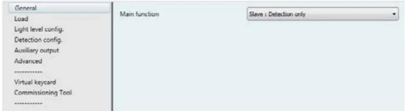
13.2.4 Slave: Detection only
| Parameters Settings | |
| Main function Master: Light level only | Master: Detection onlyMaster: Light level & detectionSlave: Detection only |
You can configure the detection,, Advance config in the different page associated, and regulation is not active. You can associate the sensors with the sensor master to extend the detection zone, see the configuration § 13.5.
13. COMMUNICATION OBJECTS (continued)
■13.3 Load
Page only available for Master: Light level Only, Master: Detection Only and Master: Light level & Detection modes.
| No. | Object name Function | Size Flags | ||
| 1 | Switching Switching 1.001 DP_On/Off CT | |||
| Switching telegrams are sent via the group address linked to this object | ||||
| 2 | Switching Status | Switching Status | 1.001 DP_On/Off | CWTU |
| Switching statuses are received via the group address linked to this object.* If switching statuses are received but the Switching object has not been sent by the sensor, the regulation is stopped. | ||||
13.3.1 Use dimming load
| Parameters | Settings |
| Use dimming load | YesNo |
No: Level, level status and In_Sync_Dim cannot be used, no accessible communication objects

| No. | Object name Function | Size Flags | ||
| 3 | Level | Level | 5.001 DP Percentage | CT |
| Level telegrams are sent via the group address linked to this object | ||||
| 4 | Level status | Level status | 5.001 DP Percentage | CWTU |
| Level statuses are received via the group address linked to this object.*If Level statuses are received but the Level object has not been sent by the sensor, the regulation is stopped. | ||||
| 9 In | Synchro dimming | In Synchro dimming | 3.007 DP_dimming control | CW |
| In override dimming values are received via the group address linked to this object.Any value received on this object is considered to be an override. | ||||
13. COMMUNICATION OBJECTS (continued)
■ 13.3 Load (continued)
13.3.2 Use expert parameters
Parameters only available for Master Light level Only and Master Light level & Detection modes.
| Parameters Settings | |
| Dimming expert configuration Yes | No |
No: Use for the current load type

When dimming expert configuration is yes: this object communication is available.
| No. | Object name Function | Size Flags | ||
| 24 | Syncro_MinimumLevel | Syncro_MinimumLevel | 5.001 DP Percentage | CRW |
Synchro_MinimumLevel values are received via the group address linked to this object
| Parameters Settings | |
| Minimum level | 0-100 |
| This parameter determines the minimum level of the actuator | |
| Maximum level | 0-100 |
| This parameter determines the maximum level of the actuator | |
| Time from Off state to On (100%) state | 1-60 |
| This parameter determines the time (in seconds) for the actuator to change from OFF to ON (0% to 100%) | |
| Load curve | LinearType 1 (DALI)CustomReservedReserved |
This parameter determines the response curve of the actuator
13. COMMUNICATION OBJECTS (continued)
■ 13.3 Load (continued)
13.3.3 Standby time base (function only available in Master mode: detection and Master: Light level & Detection)
Parameters only available for Master Light level Only and Master Light level & Detection modes.
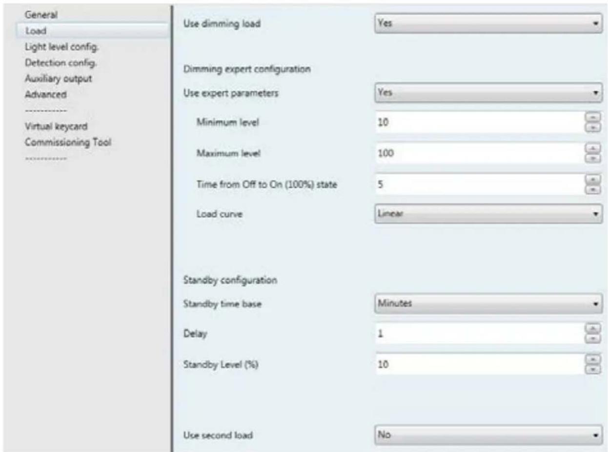
- Standby configuration :
You alert the user to the switch off the light: after the last detection (plus detection time delay) you can reduce the level of light.
| Parameters Settings | |
| Standby time base Disable | InfiniteSecondsMinutes |
Disable: Standby is not active
Infinite: At the end of time delay the load decreases to standby level for an infinite time
Seconds: At the end of time delay the load decreases to standby level for the standby time in seconds
Minutes: At the end of time delay the load decreases to standby level for the standby time in minutes
13. COMMUNICATION OBJECTS (continued)
■ 13.3 Load (continued)
13.3.3 Standby time base (function only available in Master mode: detection and Master: Light level & Detection) (continued)
- Standby time base → Seconds
A standby function, in seconds, is used. At the end of time delay the load decreases to standby level for the standby time in seconds.
| Parameters Settings | |
| Delay 0-60 | |
| This parameter determines the time for the standby in seconds | |
| Standby level 0-100 | |
| This parameter determines the standby level (default value 10%) | |
- Standby time base -Minutes
A standby function, in minutes, is used. At the end of time delay the load decreases to standby level for the standby time in minutes.
| Parameters Settings | |
| Delay 0-60 | |
| This parameter determines the time for the standby in minutes | |
| Standby level 0-100 | |
| This parameter determines the standby level (default value 10%) | |
- Standby time base—Infinite
An infinite standby function is used. At the end of time delay the load decreases to standby level for an infinite time.
| Parameters Settings | |
| Standby level 0-100 | |
| This parameter determines the standby level (default value 10%) | |
13. COMMUNICATION OBJECTS (continued)
■ 13.3 Load (continued)
13.3.4 Use second load
| Parameters Settings | |
| Use second load Yes | No |
No: Switching second light and level second light cannot be used, no accessible communication objects
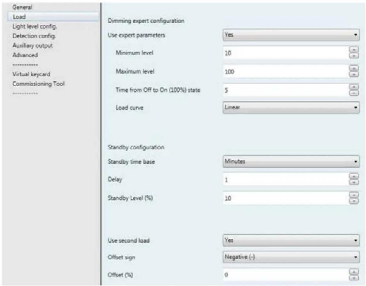
When use second load is yes: this object communication is available.
| No. | Object name Function | Size Flags | ||
| 22 | Switchingsecond light | Switchingsecond light | 1.001 DP_On/Off CRT | |
Switching second light telegrams are sent via the group address linked to this object. Used to pilot on On/Off 2 ^nd light with an offset compared to 1 ^st load.
| 23 | Level second light | Level second light | 5.001 DP Percentage | CRT |
Level second light telegrams are sent via the group address linked to this object. Used to pilot on dimming 2^nd light with an offset compared to 1^st load.
| Parameters Settings | |
| Offset sign | NegativePositive |
| This parameter determines the sign of the offset value | |
| Offset (%) | 0-100 |
| This parameter determines the offset value | |
13. COMMUNICATION OBJECTS (continued)
■13.4 Light level config
Page only available for Master: Light level Only and Master: Light level & Detection modes.
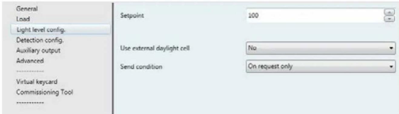
Parameters Settings
Setpoint 0 Lux...100 Lux....1275 Lux
This parameter represents the set luminosity threshold to be maintained. It is expressed in Lux
13.4.1 Use external daylight cell
For light régulation you choose if you use lux value measured by the sensor (No) or you can use an external daylight cell (Yes) see below.
| Parameters Settings | |
| Use external daylight cell No | Yes |
| Send condition On request only | On changeCyclicalOn change + Cyclical |
On request only: The object value is updated but not sent
On change: The object value is sent when it changes
Cyclical: The object value is sent cyclically
On change + Cyclical: The object value is sent when it changes and cyclically
| No. | Object name Function | Size Flags | ||
| 8 | Out Lux | Out Lux | 9.004 DP_Lux | CRT |
| Out Lux values are sent via the group address linked to this object.Send operations can be set in ETS (Cyclical, on change, on request) | ||||
13. COMMUNICATION OBJECTS (continued)
■3.4 Light level config (continued)
13.4.1 Use external daylight cell (continued)
On change
| Parameters Settings | |
| Max. number of messages per minute 1-60 | |
| This parameter determines the maximum number of messages per minute | |
| Dead band 1-100 | |
| This parameter determines the percentage variation for validating a change | |
Cyclical
The object value is sent cyclically
| Parameters Settings | |
| Cyclical interval (seconds) 1-255 | |
| This parameter determines the timebase for sending lux in seconds | |
On change + Cyclical
| Parameters Settings | |
| Cyclical interval (seconds) 1-255 | |
| This parameter determines the timebase for sending lux in seconds | |
Max. number of messages per minute 1-60
This parameter determines the maximum number of messages per minute. The value must be higher than the timebase/60.
| Dead band 1-100 | |
| This parameter determines the percentage variation for validating a change | |
When use external daylight cell is yes: this object communication is available.
| No. | Object name | Function | Size | Flags |
| 7 | In Lux | In Lux | 9.004 DP_Lux | CW |
In Lux values are received via the group address linked to this object. The sensor reacts as if it had an internal daylight cell
Warning: When an external daylight cell is used, the provision of light must be set with the IR commissioning tool.
13. COMMUNICATION OBJECTS (continued)
■13.5 Detection config
Page only available for Master Detection Only and Master Light level & Detection modes.
| No. | Object name Function | Size Flags | ||
| 5 | In Occupancy | In Occupancy | 1.002 DP_Bool | CW |
In Occupancy statuses are received via the group address linked to this object.
True: The sensor reacts as if there was an internal detection
False: No reaction
| 6 | Out Occupancy | Out Occupancy | 1.002 DP_Bool | CRT |
Out Occupancy statuses are sent via the group address linked to this object
True: When motion detected
False: After vacancy time delay, or occupancy if vacancy is not used
| 20 | Out Synchro Master → Slave | Out Synchro Master → Slave | 1.002 DP_Bool | CT |
Out synchro Master-> Slave statuses are sent via the group address linked to this object
True: The maintain status is sent to the slave
False: The initial status is sent to the slave

| Parameters | Settings |
| Use detection LED | YesNo |
| This parameter determines whether or not the detection LED is to be used when detection is active | |
| Time delay: hours | 0-17 |
| This parameter determines the hours of the time delay | |
| Time delay: minutes | 0-59 |
| This parameter determines the minutes of the time delay | |
| Time delay: seconds | 0-59 |
| This parameter determines the seconds of time delay. If the total value is less than 5 s the time delay is automatically set to 5 s | |
| Transfer In Occupancy to "Occupancy Status" | YesNo |
| This parameter determines how many "presence events" are transmitted on the bus. Is "yes" the presence events of all sensors being part of the master-slave configuration are passed on the KNX/BUS; This configuration is useful for an external supervisor. If "no" only the presence event of the master sensor is passed on the KNX/BUSYes: you have the occupancy status for each sensors : master and slaves .usefull for example in supervisionNo: you have one occupancy status for all sensors of the detection zone.You can use it to pilot a corridor for example. | |
13. COMMUNICATION OBJECTS (continued)
■ 13.5 Detection config (continued)
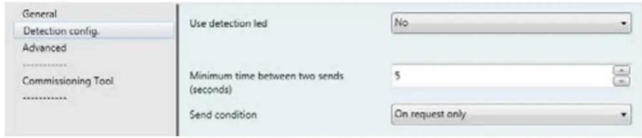
13.5.1 Send Condition
Page only available for Slave Detection Only mode.
| Parameters Settings | |
| Send condition On request only | On changeCyclicalOn change + Cyclical |
| On request only: The object value is updated but not sentOn change: The object value is sent when it changesCyclical: The object value is sent cyclicallyOn change + Cyclical: The object value is sent when it changes and cyclically | |
On request only
The object value is updated but not sent
On change
The object value is sent when detection is validated
| Parameters Settings | |
| Max. number of messages per minute 1-60 | |
| This parameter determines the maximum number of messages per minute | |
Cyclical
The object value is sent cyclically
| Parameters Settings | |
| Cyclical interval (seconds) 1-255 | |
| This parameter determines the timebase for sending lux in seconds | |
On change + Cyclical
| Parameters Settings | |
| Cyclical interval (seconds) 1-255 | |
| This parameter determines the timebase for sending lux in seconds | |
| Max. number of messages per minute 1-60 | |
| This parameter determines the maximum number of messages per minute.The value must be higher than the timebase/60. | |
13. COMMUNICATION OBJECTS (continued)
■13.6 Auxiliary output
Page only available for Master: Detection Only, Master: Light level & Detection and Slave: Detection Only modes
| Parameters Settings | |
| Auxiliary object type None | SwitchtingScaled valueHVAC ModeScene2 bytes value |
13.6.1 None
The auxiliary output cannot be used, no accessible communication objects.
13.6.2 Switching
| GeneralLoadLight level config.Detection config. | Auxiliary object type | Swichting |
| Send on occupancy | Yes | |
| Value | Off | |
| Send on vacancy | Yes | |
| Value | Off |
| No. O | object name Function | Size Flags | ||
| 11 | Switching Auxiliary | Switching Auxiliary | 1.001 DP_On/Off | CT |
| Switching Auxiliary telegrams are sent via the group address linked to this object | ||||
| Parameters Settings | |
| Send on Occupancy | YesNo |
| This parameter determines the reaction of the auxiliary on occupancy | |
| Value | OnOff |
| This parameter determines the value to send on occupancy | |
| Send on Vacancy | YesNo |
| This parameter determines the reaction of the auxiliary on vacancy | |
| Value | OnOff |
| This parameter determines the value to send on occupancy | |
13. COMMUNICATION OBJECTS (continued)
■ 13.6 Auxiliary output (continued)
13.6.3 Scaled values
| General | |
| Load | |
| Light level config. | |
| Detection config. | |
| Auxiliary output | |
| Advanced | |
| Virtual keycard | |
| Commissioning Tool |
| No. | Object name Function | Size Flags | ||
| 11 | Scaling Auxiliary | Scaling Auxiliary | 5.001 DP_Scaling | CW |
Scaling Auxiliary telegrams are sent via the group address linked to this object
| Parameters Settings | |
| Send on Occupancy | YesNo |
| This parameter determines the reaction of the auxiliary on occupancy | |
| Value | 0-100 |
| This parameter determines the value to send on occupancy | |
| Send on vacancy | YesNo |
| This parameter determines the reaction of the auxiliary on vacancy | |
| Value | 0-100 |
| This parameter determines the value to send on vacancy | |
13. COMMUNICATION OBJECTS (continued)
■ 13.6 Auxiliary output (continued)
13.6.4 HVAC Mode
| GeneralLoadLight level config.Detection config. | Auxiliary object type | HVAC Mode |
| Send on occupancy | Yes | |
| Value | 0 | |
| Send on vacancy | Yes | |
| Value | 0 |
| No. | Object name Function | Size Flags | ||
| 11 | HVAC Mode HVAC Mode | 20.102 DP_ | HVACMode | CW |
Percent auxiliary telegrams are sent via the group address linked to this object
| Parameters Settings | |
| Send on Occupancy Yes | No |
| This parameter determines the reaction of the auxiliary on occupancy | |
| Value | 0-255 |
| This parameter determines the value to send on occupancy | |
| Send on vacancy | YesNo |
| This parameter determines the reaction of the auxiliary on vacancy | |
| Value | 0-255 |
| This parameter determines the value to send on vacancy | |
13. COMMUNICATION OBJECTS (continued)
■ 13.6 Auxiliary output (continued)
13.6.5 Scene
| General | |
| Load | |
| Light level config. | |
| Detection config. | |
| Auxiliary output | |
| Advanced | |
| Virtual keycard | |
| Commissioning Tool |
| No. | Object name Function | Size Flags | ||
| 11 | 8-bit sceneAuxiliary | 8-bit sceneAuxiliary | 17,001 DP_SceneNumber | CW |
8-bit scene auxiliary telegrams are sent via the group address linked to this object
| Parameters Settings | |
| Send on Occupancy Yes | No |
| This parameter determines the reaction of the auxiliary on occupancy | |
| Value 1-64 | |
| This parameter determines which scene (1..64) to send on occupancy.If value "0" is set, no scene will be recalled. | |
| Send on vacancy | YesNo |
| This parameter determines the reaction of the auxiliary on vacancy | |
| Value 1-64 | |
| This parameter determines which scene (1..64) to send on vacancy.If value "0" is set, no scene will be recalled. | |
13. COMMUNICATION OBJECTS (continued)
■ 13.6 Auxiliary output (continued)
13.6.6 2 bytes value
| General | |
| Load | |
| Light level config. | |
| Detection config. | |
| Auxiliary output | |
| Advanced | |
| Virtual keycard | |
| Commissioning Tool |
| No. | Object name Function | Size Flags | ||
| 11 2 | byte unsignedAuxiliary | 2-byte unsignedAuxiliary | 9.001 DP_Value_Temp | CRT |
2-bytet unsigned auxiliary telegrams are sent via the group address linked to this object
| Parameters Settings | |
| Send on Occupancy Yes | No |
| This parameter determines the reaction of the auxiliary on occupancy | |
| Value 0-65535 | |
| This parameter determines the value to send on occupancy | |
| Send on vacancy | YesNo |
| This parameter determines the reaction of the auxiliary on vacancy | |
| Value 0-65535 | |
| This parameter determines the value to send on vacancy | |
13. COMMUNICATION OBJECTS (continued)
■13.7 Advanced
Page only available for Master: Detection Only, Master: Light level Only and Master: Light level & Detection modes.
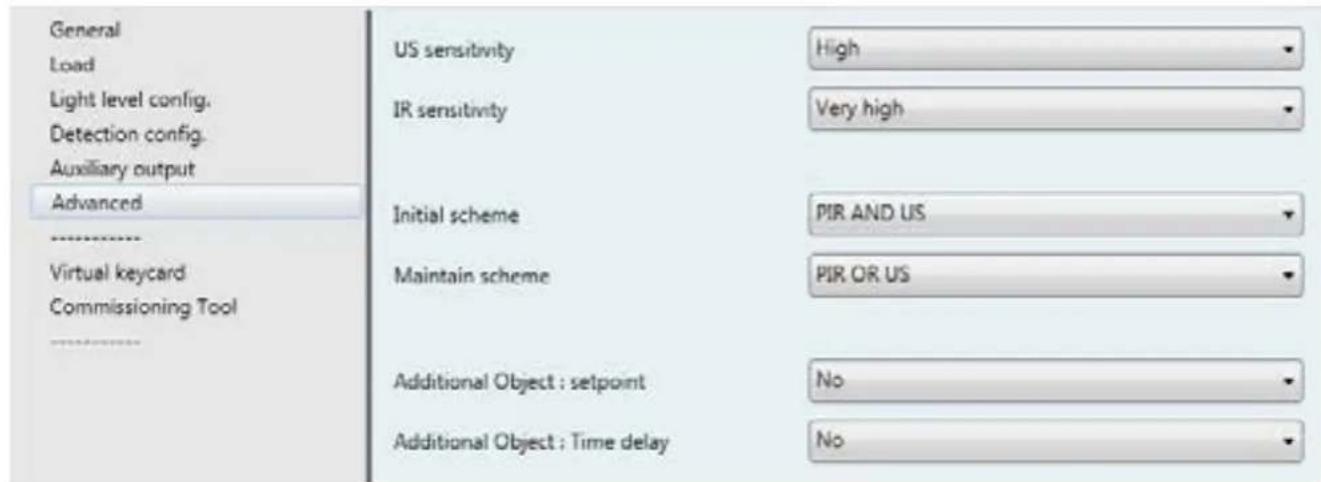
13.7.1 Sensitivity (only available for Master: Detection Only, Master: Light level & Detection and Slave: Detection Only modes)
| Parameters Settings | |
| US sensitivity Low | MediumHighVery high |
| This parameter determines the sensitivity of ultrasound sensors | |
| PIR sensitivity Low | MediumHighVery high |
| This parameter determines the sensitivity of PIR sensors | |
13.7.2 System detection (only available for Master: Detection Only, Master: Light level & Detection and Slave: Detection Only modes)
| Parameters Settings | |
| Initial scheme PIR only | US onlyPIR and USPIR or US |
| This parameter determines the sensor detection system for initialising motion detection | |
| Maintain scheme PIR only | US onlyPIR and USPIR or US |
| This parameter determines the sensor detection system for maintaining motion detection | |
13. COMMUNICATION OBJECTS (continued)
■3.8 Advanced (continued)
13.7.3 Additional object for expert mode
Here should be explained the 2 objects "Additional object: setpoint" and "Additional object: Time delay"
With these 2 "Additional object, you change parameters setpoint and Time delay" of the sensors by a supervisor for example.
| Parameters Settings | |
| Additional Objec: setpoint No | Yes |
| No: Additional object cannot be used, no accessible communication objects | |
| Additional Objec: Timedelay No | Yes |
| No: Additional object cannot be used, no accessible communication objects | |
When additional object setpoint and time delay is yes: this object communication is available.
| No. | Object name Function | Size Flags | ||
| 15 | Setpoint | Setpoint | 9.004 DP_Lux | CRW |
Occupancy setpoints are received via the group address linked to this object.
You can change day light level via the group adress linked to this object.
*Only accessible if internal or external daylight cell is used.
| 17 | TimeDelay | TimeDelay | 7.005 DP_Time_Period_Sec | CRW |
Occupancy TimeDelays are received via the group address linked to this object.
If the value received is less than 5 s the time delay is set automatically to 5 s.
You can change the value by supervisor.
If the value received.
| 19 | Recall | Recall | 1.010 DP_Start/stop | CW |
Recalls are received via the group address linked to this object.
Start: Recalls the initial values of Setpoint and TimeDelay; the values configured before the changes operated via objects.
Stop: No reaction.
13. COMMUNICATION OBJECTS (continued)
■13.8 Virtual Keycard
The function is triggered by the "door contact" event which launch the so called "Virtual keycard time delay", a time offset in which the sensor understand if the room is occupied or not, based on some informations: sensor detection, door contact events, push buttons event. Once the result of the function is "occupied" it remains until there is another "Door contact event" which trigger another "Virtual keycard time delay" to understand the room status and eventually turn OFF the lights, launch an absence scenario or launch any other logic related to vacancy event.
Page only available for Master Detection Only and Master Light level & Detection modes.
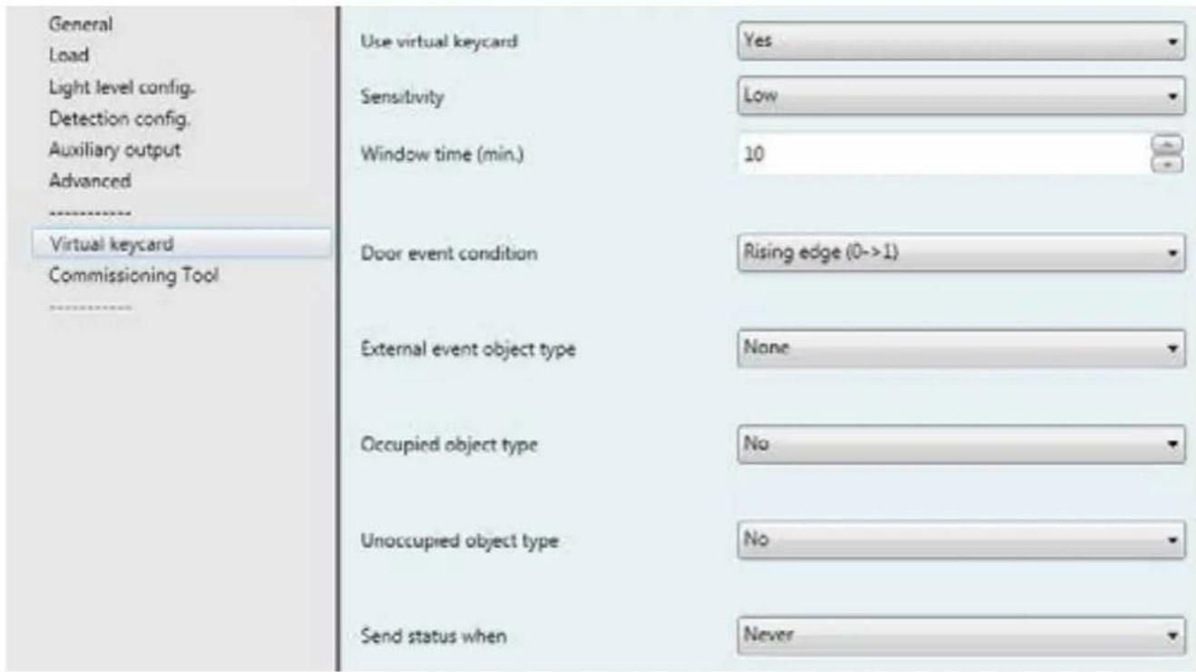
13.8.1 Use Virtual Keycard
| Parameters Settings | |
| Use virtual keycard No | Yes |
No: The virtual keycard function cannot be used, no accessible communication objects
When use virtualkeycard is yes: this object communication is available.
| No. | Object name Function | Size Flags | ||
| 31 | Virtual Keycard | Door contact | 1.001 DP_On/Off | CRWTU |
VKC_Door_contact telegrams are received via the group address linked to this object
| 33 | Virtual Keycard | Status | 1 bit | CT |
| VKC Statuses are sent via the group address linked to this object | ||||
| 36 | Virtual Keycard | In detection | 1.003 DP_Boolean | CW |
VKC in detection telegrams are received via the group address linked to this object
With object 36 is possible to associate others sensors and extend the detection zone of the first sensor.
13. COMMUNICATION OBJECTS (continued)
■13.8 Virtual Keycard (continued)
13.8.1 Use Virtual Keycard (continued)
13.8.1.1 Sensitivity
| Parameters Settings | |
| Sensitivity Low | MediumHighVery high |
| This parameter determines the numbers of detections needed to confirm presence.Low: 5 detections in 20 secondsMedium: 4 detections in 20 secondsHigh: 3 detections in 20 secondsVery high: 2 detections in 20 seconds | |
13.8.1.2 Window time (min)
| Parameters Settings | |
| Window time (min) 3-255 | |
| This parameter is the "Virtual keycard time delay". It determines the delay after a door contact in which the sensor check if there is presence and change the status from absence (object status=0) to presence (object status=1). | |
13.8.1.3 Door event condition
| Parameters Settings | |
| Door event condition Rising edge 0 | →1Falling edge 1 -0 |
This parameter determines the door event condition on the VKC door contact object. It determines if the «door contact event» is measured on the rising or falling edge
| No. | Object name | Function | Size | Flags |
| 31 | Virtual Keycard | Door contact | 1.001 DP_On/Off | CRWTU |
VKC_Door_contact telegrams are received via the group address linked to this object
13. COMMUNICATION OBJECTS (continued)
■13.8 Virtual Keycard (continued)
13.8.1 Use Virtual Keycard (continued)
13.8.1.4 External event object type
External event object type
Switch
External event comparator
简要
Compared value
Off
| Parameters Settings | |
| External event object type None | SwitchScaled valueScene2-bytes4-bytes |
This parameter determines the Data point type of the VKC external object.
This object is used to improve the function effectiveness, it is an additional object used to confirm the presence information. It can be a command switch, detection in the room, window contact...
External event comparator == (equal)
| != (different) |
| < (less than) |
| <=(less than or equal) |
| >(greater than) |
| >=(greater than or equal) |
This parameter determines the type of comparison between the value on a VKC external object and the value to be compared
Compared value On (Switch)
| Off (Switch) |
| 0-100 (Scaled value) |
| 1-64 (Scene) |
| 0-64 (Scene) |
| 0-65535 (2-bytes) |
| 0-4294967295 (4 bytes) |
This is the type of value to be compared
| No. | Object name Function | Size Flags | ||
| 32 | Virtual Keycard | External event | DPT depend on the choice made in the settings | CW |
VKC_external event telegrams are received via the group address linked to this object. DPT depend on the choice made in the settings
13. COMMUNICATION OBJECTS (continued)
■13.8 Virtual Keycard (continued)
13.8.1 Use Virtual Keycard (continued)
13.8.1.5 Occupied and Unoccupied object type
Action on presence and absence event.
Occupied object type
No
Unoccupied object type
No
| Parameters Settings | |
| Occupied object type No | SwitchScaled valueHVAC ModeScene2-bytes value |
| This parameter determines the Data point type of the VKC presence action object | |
| Value On (Switch) | Off (Switch)0-100 (Scaled value)0-255 (HVAC Mode)1-64 (Scene)0-65535 (2-bytes) |
| Value to send to the VKC occupied object | |
| Unoccupied type object No | SwitchScaled valueHVAC ModeScene2-bytes value |
| This parameter determines the Data point type of the VKC absence action object | |
| Value On (Switch) | Off (Switch)0-100 (Scaled value)0-255 (HVAC Mode)1-64 (Scene)0-65535 (2-bytes) |
| Value to send to the VKC Unoccupied object | |
• Example with a Switch object type
| Occupied object type | Switch |
| Value | On |
| Unoccupied object type | Switch |
| Value | Off |
| No. | Object name Function | Size Flags | ||
| 34 | Virtual Keycard | VKC_presence_action_1bit | Switch CT |
VKC presence actions are sent via the group address linked to this object. DPT depend on the choice made in the settings
| 35 | Virtual Keycard | VKC_absence_action_1bit | Switch CT |
VKC absence actions are sent via the group address linked to this object. DPT depend on the choice made in the settings
13. COMMUNICATION OBJECTS (continued)
■13.8 Virtual Keycard (continued)
13.8.1 Use Virtual Keycard (continued)
13.8.1.6 Send status when
Send status when
Never
| Parameters Settings | |
| Send status when Never | Occupied onlyUnoccupied onlyOccupied & unoccupied |
This parameter determines when to send a value on the VKC status object Never: No value sent to VKC status, but can be read on request Occupied: Only occupied is sent to VKC status (Occupied) Unoccupied: Only unoccupied is sent to VKC status (Not occupied) Occupied & unoccupied: Both are sent to VKC status (Occupied and Not occupied)
13.8.2 Virtual keycard function operating diagram

flowchart
graph LR
    A["(Action Push Button Room for example)"] --> B["Sensor 2"]
    B --> C["Status occupancy"]
    B --> D["External event"]
    D --> E["Sensor 1"]
    E --> F["(Supervision for example)"]
    E --> G["VKC Presence action"]
    E --> H["VKC Absence action"]
    E --> I["Door contact Virtual Keycard Status"]
Virtual keycard behaviour:

flowchart
graph LR
    A["Occupied"] --> B["Start"]
    B --> C["VKC delay"]
    C --> D["Not occupied"]
    D --> E["Presence detection"]
    E --> F["Door contact event"]
    F --> G["Unknown"]
    G --> H["End"]
    H --> I["Presence detection"]
    I --> J["Door contact event"]
    J --> K["Presence detection"]
    K --> L["Door contact event"]
    L --> M["External event"]
    M --> N["Unknown"]
    N --> O["Presence detection"]
    O --> P["Door contact event"]
    P --> Q["Presence detection"]
    Q --> R["Unknown"]
    R --> S["End"]
VKC function is triggered by "door contact" event after which begins the "VCK time delay" to understand if there is or not presence in the room. If during this time offset nothing is detected the result of the function is "vacancy" and the logics tied to the VKC function are not activated (first half of the above diagram). In case of detection during the time offset the result of the function is "occupancy", the "VKC time delay" is stopped and the related logics are triggered (second half of the above diagram). The VCK time delay restarts after another "door contact event". During the "VCK time delay" the "occupancy" status can be determined by the combination of more events: presence sensor "detection event" or external events (window contact, push-button pressure...).
13. COMMUNICATION OBJECTS (continued)
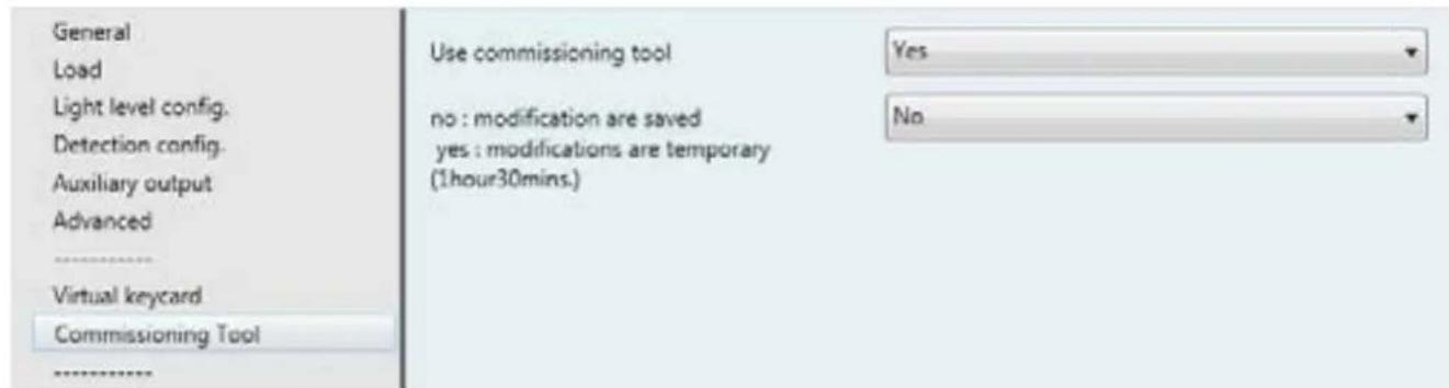
■13.9 Commissioning Tool
| Parameters Settings | |
| Use commissioning tol Yes | No |
| No: The sensor parameters can be only read with the commissioning toolYes: The sensor parameters can be changed with the commissioning tool | |
| No: modification are saved No | Yes |
| No: Modifications are saved to the memory but change when a new application with ETS is downloadedYes: Modifications are applied for 1 hour 30 minutes after the product has reloaded the default value; or if the product is disconnected from the bus, the default value isreloaded when the product is reconnected | |
13. COMMUNICATION OBJECTS (continued)
■13.10 Pushbutton
13.10.1 Pushbutton function
13.10.1.1 Function: Not used
The pushbutton cannot be used, no accessible communication objects
13.10.1.2 Function: Switching
| General | |
| Load | |
| Light level config. | |
| Detection config. | |
| Auxiliary output | |
| Advanced | |
| ---- | |
| Virtual keycard | |
| Commissioning Tool | |
| ---- | |
| Push button |
| No. | Object name Function | Size Flags | ||
| 25 | BP_Switching Switching | Push_Button | 1.001 DP_On/Off CWT | |
Switching pushbutton telegrams are sent via the group address linked to this object
| 30 BP_Enable Enable_ | Push_Button | 1.003 DP_Enable CRW |
Disable telegrams are received via the group address linked to this object. They are used to lock (disable) or unlock (enable) the pushbutton
| Parameters Settings | |
| Short push reaction | NoneOnOffToggle |
Here an adjustment is made to define which switching value is written to the storage cell of the communication object and sent after a short press on the pushbutton attached to the input.
"None": A short press on the pushbutton does not change the object value and also does not lead to a telegram being sent.
"On": After a short press on the pushbutton, the switching value "ON" (binary value, "1") is transferred to the communication object and sent.
"Off": After a short press on the pushbutton, the switching value "OFF" (binary value,"0") is transferred to the communication object and sent.
"Toggle": After a short press on the pushbutton, the switching value stored in the communication object is inverted and the new value is sent.
| Long push reaction | NoneOnOffToggle |
Here an adjustment is made to define which switching value is written to the storage cell of the communication object and sent after a long press on the pushbutton attached to the input.
"None": A long press on the pushbutton does not change the object value and also does not lead to a telegram being sent.
"On": After a long press on the pushbutton, the switching value "ON" (binary value, "1") is transferred to the communication object and sent.
"Off": After a long press on the pushbutton, the switching value "OFF" (binary value,"0") is transferred to the communication object and sent.
"Toggle": After a long press on the pushbutton, the switching value stored in the communication object is inverted and the new value is sent
| Long push time | 0.5 s |
| 1 s | |
| 2 s | |
| 3 s | |
| 4 s | |
| 5 s | |
| 10 s |
This parameter determines the minimum period for detecting a long press on the pushbutton
13. COMMUNICATION OBJECTS (continued)
■3.10 Pushbutton (continued)
13.10.1 Pushbutton function (continued)
13.10.1.3 Function: Dimming

| No. | Object name Function | Size Flags | ||
| 25 | BP_Switching SwitchingPush_Button | 1.001 DP_On/Off CWT | ||
Switching pushbutton telegrams are sent via the group address linked to this object
| 27 | BP_Dimming | DimmingPush Button | 3.007 DP_dimming control | CT |
Level telegrams are sent via the group address linked to this object
| 30 | BP_Enable | EnablePush_Button | 1.003 DP_Enable CRW |
Disable telegrams are received via the group address linked to this object. They are used to lock (disable) or unlock (enable) the pushbutton
| Parameters | Settings |
| Short push reaction | NoneOnOffToggle |
Here an adjustment is made to define which switching value is written to the storage cell of the communication object and sent after a short press on the pushbutton attached to the input.
"None": A short press on the pushbutton does not change the object value and also does not lead to a telegram being sent.
"On": After a short press on the pushbutton, the switching value "ON" (binary value, "1") is transferred to the communication object and sent.
"Off": After a short press on the pushbutton, the switching value "OFF" (binary value,"0") is transferred to the communication object and sent
"Toggle": After a short press on the pushbutton, the switching value stored in the communication object is inverted and the new value is sent.
| Long push reaction | NoneCyclical dim +/- |
| Here an adjustment is made to define which dimming value is written to the storage cell of the communication object and sent after a long press on the pushbutton attached to the input."None": A long press on the pushbutton does not change the object value and also does not lead to a telegram being sent."Cyclical dim +/-": After a long press on the pushbutton, the dimming value stored in the communication object is inverted and the new value is sent. | |
| Long push release | NoneDim stop |
Here an adjustment is made to define which dimming value is written to the storage cell of the communication object and sent when a long press on the pushbutton attached to the Channel is released
"None": A long press on the pushbutton does not change the object value and also does not lead to a telegram being sent.
"Dim stop": When the pushbutton is released after a long press, the dimming value "Stop" is transferred to the communication object and sent.
| Long push time | 0.5 s |
| 1 s | |
| 2 s | |
| 3 s | |
| 4 s | |
| 5 s | |
| 10 s |
This parameter determines the minimum period for detecting a long press on the pushbutton
13. COMMUNICATION OBJECTS (continued)
■ 3.10 Pushbutton (continued)
13.10.1 Pushbutton function (continued)
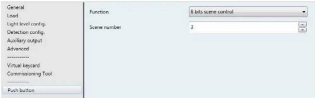
13.10.1.4 Function: 8-bit scene control
| No. | Object name Function | Size Flags | ||
| 29 | BP_Outscene Outscene | Push_Button | 1.001 DP_On/Off CWT | |
Switching pushbutton telegrams are sent via the group address linked to this object
| 30 | BP_Enable | Enable_Push_Button | 1.003 DP_Enable CRW |
Disable telegrams are received via the group address linked to this object. They are used to lock (disable) or unlock (enable) the pushbutton
| Parameters | Settings |
| Scene number | 1-64 |
| This parameter determines which scene (1-64) is to be recalled on a rising edge when mode 1 is activeIf value “0” is set, no scene will be recalled | |
14. APPLICATION'S EXAMPLES
Following are described some common applications.
Here are listed the involved products and the needed objects, to be connected, in order to realize the described functions.
■14.1 Mode Auto ON/OFF - Load ON/OFF
The represented associations are valid in the following configuration cases:
• light level only with regulation
• detection only without regulation
• light level and detection without regulation
• light level and detection with regulation

flowchart
graph LR
    A["Status Switching Status Switching"] --> B["Sensor"]
    B --> C["Actuator ON/OFF"]
    C --> D["In on/off"]
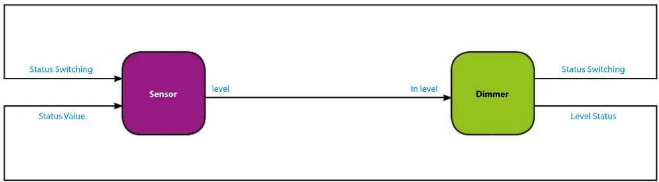
■14.2 Mode Auto ON/OFF - Dimming load
The represented associations are valid in the following configuration cases:
• detection only without regulation
• light level only with regulation
• light level and detection without regulation
• light level and detection with regulation
flowchart
graph LR
    A["Status Switching"] --> B["Sensor"]
    C["Status Value"] --> B
    B -->|level| D["Dimmer"]
    D -->|In level| D
    D --> E["Level Status"]
    style B fill:#d4edda,stroke:#333
    style D fill:#d4edda,stroke:#333
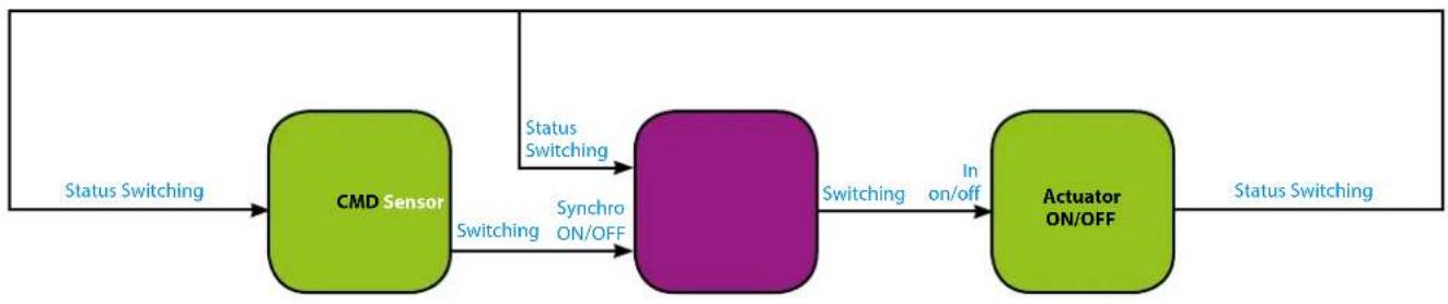
■14.3 Mode Manual ON/Auto OFF – Load ON/OFF
The represented associations are valid in the following configuration cases:
• detection only without regulation
• light level only with regulation
• light level and detection without regulation
• light level and detection with regulation
flowchart
graph LR
    A["Status Switching"] --> B["CMD Sensor"]
    B -->|Switching| C["Synchro ON/OFF"]
    C -->|Switching| D["Actuator ON/OFF"]
    D -->|In on/off| C
    E["Status Switching"] --> B
14. APPLICATION'S EXAMPLES (continued)
■14.4 Mode Manual ON/AutoOFF - Dimming load
The represented associations are valid in the following configuration cases:
• detection only without regulation
• light level only with regulation
• light level and detection without regulation
• light level and detection with regulation

flowchart
graph LR
    A["CMD"] -->|Switching| B["Sensor"]
    B -->|Level| C["Dimmer"]
    C -->|In level| B
    B -->|Dimming| C
    A -->|Dimming In Synchro| B
    B -->|Status Switching| A
    C -->|Status Switching| A
    style A fill:#90EE90
    style B fill:#FFB6C1
    style C fill:#90EE90
■14.5 Master/Slave detection
The represented associations are valid in the following configuration cases:
Ex: without regulation/load ON/OFF

flowchart
graph LR
    A["Slave sensor"] -->|In Occupancy| B["Master sensor"]
    A -->|Out Occupancy| B
    B -->|Switching| C["Actuator"]
    C -->|In Switching| B
    C -->|Status Switching| D["Master Sensor"]
    D -->|In Occupancy| A
    D -->|Out Occupancy| A
- USE
- TECHNICAL FEATURES
- ■ 3.1 Electrical features
- ■ 3.2 Climatic features
- ■ 3.3 Mechanical features
- DIMENSIONS
- CONNECTION
- INSTALLATION
- OPERATION
- Functions:
- Partial on/Group off Mode:
- SETTINGS
- Detection system:
- SETTINGS (continued)
- - Restore to factory settings:
- PERFORMANCE
- PERFORMANCE (continued)
- STANDARDS AND APPROVALS
- Note:
- MAINTENANCE
- Caution:
- COMMUNICATION OBJECTS
- ■ 13.1 List of objects
- COMMUNICATION OBJECTS (continued)
- ■13.2 General parameters
- Main function - Master: Light level only
- Mode
- • Auto on/Auto off mode
- - Walkthrough
- ■ 13.2 General parameters (continued)
- Main function - Master: Light level only (continued)
- Mode: Manual ON/Auto OFF (continued)
- - Use scene - Yes
- Main function - Master: Detection only
- Mode: Auto ON/OFF
- Main function - Master: Light level & Detection
- Mode: Auto ON/OFF
- Main function - Master: Light level & Detection (continued)
- Mode: Manual On/Auto Off
- Mode: Manual On/Auto Off (continued)
- Slave: Detection only
- ■13.3 Load
- Use dimming load
- ■ 13.3 Load (continued)
- Use expert parameters
- - Standby configuration :
- Standby time base (function only available in Master mode: detection and Master: Light level & Detection) (continued)
- - Standby time base -Minutes
- Use second load
- ■13.4 Light level config
- Use external daylight cell
- ■3.4 Light level config (continued)
- Use external daylight cell (continued)
- ■13.5 Detection config
- ■ 13.5 Detection config (continued)
- Send Condition
- On request only
- On change
- Cyclical
- On change + Cyclical
- ■13.6 Auxiliary output
- None
- Switching
- ■ 13.6 Auxiliary output (continued)
- Scaled values
- HVAC Mode
- Scene
- 2 bytes value
- ■13.7 Advanced
- ■3.8 Advanced (continued)
- Additional object for expert mode
- ■13.8 Virtual Keycard
- Use Virtual Keycard
- ■13.8 Virtual Keycard (continued)
- Use Virtual Keycard (continued)
- Sensitivity
- Window time (min)
- Door event condition
- External event object type
- Occupied and Unoccupied object type
- Send status when
- Virtual keycard function operating diagram
- Virtual keycard behaviour:
- ■13.9 Commissioning Tool
- ■13.10 Pushbutton
- Pushbutton function
- Function: Not used
- Function: Switching
- ■3.10 Pushbutton (continued)
- Pushbutton function (continued)
- Function: Dimming
- ■ 3.10 Pushbutton (continued)
- Function: 8-bit scene control
- APPLICATION'S EXAMPLES
- ■14.1 Mode Auto ON/OFF - Load ON/OFF
- ■14.2 Mode Auto ON/OFF - Dimming load
- ■14.3 Mode Manual ON/Auto OFF – Load ON/OFF
- APPLICATION'S EXAMPLES (continued)
- ■14.4 Mode Manual ON/AutoOFF - Dimming load
- ■14.5 Master/Slave detection
Brand : LEGRAND
Model : 078493
Category : Motion detector