
MT502 - Desk Phone Phoenix Audio - Free user manual and instructions
Find the device manual for free MT502 Phoenix Audio in PDF.


| Product Type | Desk Phone |
| Brand | Phoenix Audio |
| Model | MT502 |
| Dimensions (W x D x H) | Approximately 200 x 150 x 80 mm |
| Weight | Approximately 0.5 kg |
| Power Supply | AC adapter (input 100-240V, output 5V DC 1A) |
| Display | Backlit LCD screen |
| Keypad | Numeric keypad with dedicated function keys |
| Speakerphone | Full-duplex speakerphone for hands-free calls |
| Call Features | Call waiting, call hold, call transfer, redial, mute |
| Phonebook | Up to 100 contacts |
| Ringer | Adjustable ring volume and tone |
| Connection | RJ-11 for telephone line, RJ-9 for handset |
| Wall Mountable | Yes (mounting bracket included) |
| Hearing Aid Compatible | Yes (HAC rated) |
| Maintenance | Clean with a soft, dry cloth; avoid liquids |
| Safety | Use only specified power adapter; keep away from moisture |
| Spare Parts / Reparability | Contact Phoenix Audio support for replacement parts |
| Warranty | 1 year limited warranty |
Frequently Asked Questions - MT502 Phoenix Audio
User questions about MT502 Phoenix Audio
0 question about this device. Answer the ones you know or ask your own.
Ask a new question about this device
Download the instructions for your Desk Phone in PDF format for free! Find your manual MT502 - Phoenix Audio and take your electronic device back in hand. On this page are published all the documents necessary for the use of your device. MT502 by Phoenix Audio.
USER MANUAL MT502 Phoenix Audio
INDEX
Overview Page 03
Connecting the Spider Page 04
Using the Spider Page 05
- Dialing Page 05
- Incoming Call Page 05
- During A Call Page 06
Display Page 07
Device Menu Page 08
External Mic/Speaker Page 12
Daisy Chaining Page 14
Specifications Page 16
Warranty Page 17
SPIDER 502 PSTN OVERVIEW
The Spider is a high-quality conference speakerphone that will turn any room into a
professionally sounding conference room. It has an exceptionally large pickup and broadcasting range, yet is small in size and discreet in design.
The Spider utilizes multiple microphones, a uniquely designed speaker, and a powerful DSP to achieve commanding performance.
This guide will help you learn how to use your conference phone and will reveal all the features that come with it.


CONNECTING TO A COMPUTER
This connection is for any session using your computer, such as Voice over IP applications (Skype, Vidyo, etc.).
Using the USB cable provided, plug the micro USB side of the cable into the Spider (USB connector located on the connector panel below the unit).
Plug the USB end of the cable into any USB port on your computer.
Connect the provided Power Supply to the DC connector located on the connector panel below the unit. Once you plug the Power Supply into a power source, your Spider is ready for use.
No additional drivers or steps are needed. However, we do recommend downloading and using our "Phoenix Audio Setup Utility" for optimal audio control and performance. This utility can be found on our website: www.phnxaudio.com/downloads/audiosetup/
For any session using a PSTN/POTS/ANALOG phone line.
Using the telephone cable provided, plug one end of the cable into the Spider's RJ11 telephone jack (TEL connector located on the connector panel below the unit).
Plug the other end of the cable directly into your telephone-line wall socket.
Connect the provided Power Supply to the AC connector located on the connector panel below the unit. Once you plug the Power Supply into a power source, your Spider is ready for use.
USING THE SPIDER
DIALING
If the keypad is dimmed, press any key to turn on the backlight.
Dial the desired number and press ↗.
OR
Press 📋 to get a dial tone. The screen will display the last dialed number. Press again to redial, or dial any new number at will.
INCOMING CALL
When the Spider receives an incoming call, the display will notify you of the caller ID, a ringtone will play, and the grill lights will flash blue.
TAKE CALL
Press OR the left function button
REJECT CALL
Press OR the right function button (this will hang-up the call).
SILENCE CALL
Press the middle function button (the Spider will continue ringing, only without an audible ringtone).
THE DIRECTIONAL ARRAY
During a call the Spider uses a proprietary Beamforming technology to locate a legitimate voice source, and to steer an array towards it. This allows the Spider to focus on the speaker in the room and to cancel out all other noises.
The Beamforming process is dynamic and adjusts the direction of the array when the source of sound changes or moves. When in a call and a voice is detected in the room, a single or multiple blue lights located under the grill will indicate which direction the Spider's audio beam is focusing on. This is the direction that will be heard best by the far-end of the call (the person you are talking to).
NOTE: This function can be disabled (see page 11).
VOLUME CONTROL
Use the ▲ and ▼ buttons on the keypad to control the speaker volume during a call.
MUTE
In order to mute the Spider's microphones during a call, press the Ⓗ button located on the bottom right of the keypad. When muted, a MUTE symbol will appear on the screen and all the grill lights will flash red.
To UNMUTE, just press the Ⓗ button again.
FLASH (this function varies by region)
Press the middle function key
Commonly this will toggle between call waiting sessions.
HOLD (conference a new source into your existing call)
Press the right function key ▲.
The call will be placed on hold. All parties will be muted, and music will be playing.
Press the right function key ▲ once more to take the call off hold.
END CALL
Press the button OR the left function key
All the grill lights will show solid red for three seconds.
DISPLAY
DISPLAY SETTINGS
Can be found in the Settings section of the MAIN MENU (see page 11.)
DISPLAY TIMEOUT
The amount of time before the unit's display and keypad dim off.
DISPLAY BRIGHTNESS
Scroll using the ▲ and ▼ buttons to choose a display brightness setting.
GRILL LIGHT
Turn ON/OFF the blue and red lights that appear under the grill during a call (incoming call, mute, Beamforming, and hanging up).
CONNECTIVITY DISPLAY
On the top left corner of the screen, the Spider will display the interface it's connected to.
USB SYMBOL
If a ⬤ symbol appears, your Spider is connected to a computer and is ready to act as a microphone/speaker for that computer.
DURING A CALL
CALL TIMER
In the top left corner of the screen you will see a timer that will start when your call is picked up and will stop when the call is disconnected.
CALLER ID
The center of the screen will display the phone number the Spider is in a session with. If that number has a caller ID name, that name will be displayed.
SET CALLER ID STANDARD
For caller ID to work properly, you must set the Spider to match with your service provider's standard.
Enter the MAIN MENU by clicking on the ⚙ button.
Scroll using the ▲ and ▼ buttons and select Settings OR press 7.
Scroll using the ▲ and ▼ buttons and select Caller ID Standard OR press 5.
Select a standard, and click the left function key ▲ to save.
NOTE: Europe is typically V.23, and North America is typically Bell 202.
DEVICE MENU
To enter the menu, click on the ⚙ button.
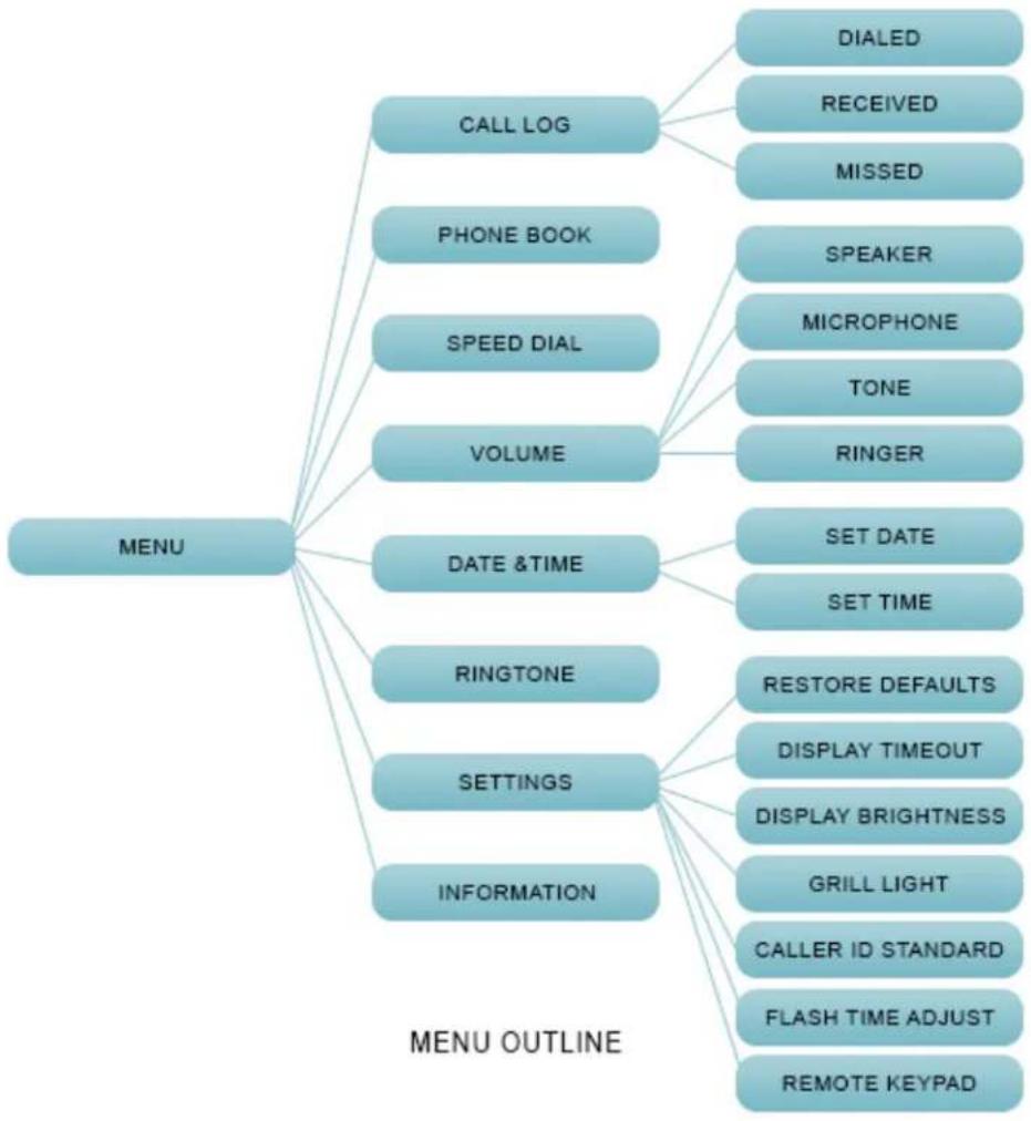
flowchart
graph TD
    A["MENU"] --> B["CALL LOG"]
    A --> C["PHONE BOOK"]
    A --> D["SPEED DIAL"]
    A --> E["VOLUME"]
    A --> F["DATE &TIME"]
    A --> G["RINGTONE"]
    A --> H["SETTINGS"]
    A --> I["INFORMATION"]
    B --> J["DIALED"]
    B --> K["RECEIVED"]
    B --> L["MISSED"]
    C --> M["SPEAKER"]
    C --> N["MICROPHONE"]
    C --> O["TONE"]
    C --> P["RINGER"]
    F --> Q["SET DATE"]
    F --> R["SET TIME"]
    G --> S["RESTORE DEFAULTS"]
    G --> T["DISPLAY TIMEOUT"]
    G --> U["DISPLAY BRIGHTNESS"]
    H --> V["GRILL LIGHT"]
    H --> W["CALLER ID STANDARD"]
    H --> X["FLASH TIME ADJUST"]
    H --> Y["REMOTE KEYPAD"]
    I --> Z["MENU OUTLINE"]
ENTER
The ⚙️ button functions as ENTER and will take you one step forward in the menu.
BACK
The right function key is BACK and will return you one step back in the menu.
EXIT
The button will EXIT the menu and will return you to the Spider's main display.
MENU CATEGORIES
CALL LOG
The Spider's call history.
You can clear complete call logs by using the middle function button in the general CALL LOG menu ▲, or clear a specific call by using the middle function button inside any of the sub-logs listed below. Scroll through the lists using the ▲ and ▼ buttons, and dial the number by selecting it with the ⚙ button or the left function button ▲. Exit back to the call log menu using the right function button ▲.
Dialed Calls
The last 1000 phone numbers dialed from the Spider.
Received Calls
The last 1000 phone numbers answered from the Spider.
Missed Calls
The last 1000 incoming phone numbers not answered from the Spider.
PHONE BOOK
Store up to 100 contact names and numbers.
You can clear the whole phone book by selecting the middle function button in the main menu, or clear a specific call by using the middle function button inside the PHONE BOOK. You can scroll through the lists using the ▲ and ▲ buttons, and dial the number by selecting it with the ⚙ button or the left function button . Exit back to the call log menu using the right function button .
SPEED DIAL
Assign up to 10 numbers that can be dialed automatically by holding down one of the numeric buttons.
VOLUME
Adjust the volume levels for the Spider's different volume profiles listed below:
Speaker
Increase or decrease the speaker volume by using ▲ and ▼.
Microphone
Increase or decrease the microphone sensitivity using ▲ and ▼.
NOTE: If the sensitivity is set too low you won't be heard by the far-end. However, if the sensitivity is set too high, the far-end might get a distorted signal.
Tone
Increase or decrease the keypad tone volume by using ▲ and ▼.
Ringer
Increase or decrease the ringtone volume by using ▲ and ▼.
DATE AND TIME
Set the device's date and time, which will be presented on the unit's display.
RINGTONE
Scroll using the ▲ and ▼ buttons to choose a ringtone.
SETTINGS
General device controls and settings.
Restore Defaults
Returns all settings to factory defaults.
Display Timeout
The amount of time before the unit's display and keypad dim off.
Display Brightness
Scroll using the ▲ and ▼ buttons to choose a display brightness setting.
Grill Light
Turn ON/OFF the blue and red lights that appear under the grill during a call (incoming call, mute, Beamforming, and hanging up).
Caller ID Standard
For caller ID to work properly, you must set the Spider to match with your service provider's standard.
Enter the MAIN MENU by clicking on the ⚙ button.
Scroll using the ▲ and ▼ buttons and select Settings OR press 7.
Scroll using the ▲ and ▼ buttons and select Caller ID Standard OR press 5.
Select a standard, and click the left function key ▲ to save.
NOTE: Europe is typically V.23, and North America is typically Bell 202.
Flash Time Adjust
Adjust the time span of the flash function.
NOTE: In order to use the flash function, the set time span must be supported by your service provider.
INFORMATION
Firmware Version
The firmware version that the Spider is running.
S/N
The Spider's serial number given by Phoenix Audio Technologies.
ID
An internal ID number.
CONNECTING AN EXTERNAL MIC AND SPEAKER
MICROPHONE ONLY
Connect the external microphone to the 3.5mm connector using a 3-pin to 4-pin adapter (the same adapter that is used to connect a standard microphone to a Smart device). Select "External Microphone" in the "Audio Jack Setting" of the Audio Setup Utility. The unit's internal speaker and microphones will continue working, along with the external microphone.
Connect the external speakers to the 3.5mm connector. The unit's built-in speaker will be muted. Make sure that the "Headset" option is selected in the "Audio Jack Setting" of the Audio Setup Utility (this should be the default).
MICROPHONE AND SPEAKERS (OR HEADPHONES WITH MIC)
Connect your headset into the 3.5mm connector, making sure that the "Headset" option is selected in the "Audio Jack Setting" of the Audio Setup Utility (this should be the default.) If you would like to use external speakers and a microphone, wire them the same way a standard Smart Phone mic'd headphone would be wired.
NOTE: Standard wiring: tip → left, ring1 → right, ring2 → ground, sleeve → mic-in
PRIVACY MODE
When using a mic'd headset, you can utilize the standard headset button to toggle between Privacy Mode (Headset Audio) and Speakerphone Mode. This allows you to leave your headset (or handset) plugged into the device when using the Spider's built-in microphone and speaker. When in Privacy Mode the two front red LEDs will blink.

DAISY CHAINING
Every Spider comes with a built in ability to connect to other SMART Spiders (MT503) or Quattro3s (up to 15 units). This feature enables you to provide coverage for larger spaces using a chain of units.
NOTE: The PSTN Spider MT502 can only act as the first or "master" unit and not as a satellite unit.

flowchart
graph TD
    A["Spider Master Unit"] -->|Link Down| B["SATELLITE UNIT 1"]
    B -->|Link Up Link Down| C["SATELLITE UNIT 2"]
    C -->|Link Up Link Down| B
The PSTN Spider will be the master unit. This unit will be the one interfacing for the entire chain. The master unit will be the only unit communicating with an external device, while all other units will connect and communicate only with each other.
Using either the provided daisy chain cable or any other Ethernet cable, connect one of the cable ends to the master unit's daisy chain DOWN connector (the RJ45 connector marked "Link Down").
Take the other end of the cable and connect it to the next unit's daisy chain UP connector (the RJ45 connector marked "UP" or "Link Up").
Repeat the process in order to connect a third unit to unit number 2. This process can be repeated with up to 15 units regardless of their interface type. All units in the chain must be Quattro3s or Spiders.
NOTE: The MT505 and MT502 can only be the master unit, or the first unit in the chain.
POWERING THE DAISY CHAIN
Every unit in the chain must be powered. In order to do this, there are two available options:
OPTION 1
Power each unit separately, using its own provided USB cable, DC power supply, or internal battery (if applicable).
OPTION 2
Power only the master unit using the “Daisy Chain Power Kit” (MT320), or the included 48V power supply. This setup will require you to connect only the first unit to a power source, and will allow the rest of the units to feed off the master unit via the Ethernet daisy chain cables.
NOTE: While any Spider or Quattro3 can be daisy chained (regardless of interface), the power daisy chain method requires all units in the chain to have some type of secondary interface card (ONLY Quattro3 MT301 will not work). The power daisy chain method will work with up to 8 consecutive units before requiring another power source. The power source can be placed anywhere in the chain (first, last, or middle units).
SPECIFICATIONS
- USB interface (micro B connector)
• 3.5mm external loudspeaker and microphone jack
• Daisy chain expandability of up to 15 units - Three-way bridging capability
• Frequency response 50Hz – 16KHz - Low latency (10ms)
- Broadcast level (peak): 92dB SPL @1m (5 watts RMS)
- Noise cancellation > 10dB (without pumping noise)
- 100% full duplex – no attenuation (in either direction) during full duplex
• High-end performance conforms to ITU-T G.167 - Acoustic echo cancellation > 40dB with conversion speed of 40dB/sec
- Residual echo is suppressed to the environment noise level, preventing artificial ducking of signal
• 4 high-quality directional microphones - Direction-finding algorithm (determines the presence and direction of a speaker)
- Beam-forming algorithm (forms and directs audio beams towards a defined direction)
• Automatic voice-level adjustment (AGC)
• Line-echo canceler active when telephone interface is present - Metal case and metal grill mesh for high RFI immunity and product durability
Dimensions: Length: 9.4" Width: 7" Height: 2.75"
Weight: 2.15 lbs.
Power Consumption: 150 mA from 48V ac/dc adaptor via PoE supply
Software: Plug- and -Play. No installation or drivers.
Note: Audio Setup Utility is available for Windows. The setup utility helps
Operating Systems: Windows 98 and up / Linux / MacOS.
Complies with FCC 47 CFR Part 68, and ACTA adopted technical criteria: TIA-968-A
Complies with FCC 47CFR part 15; ICES-003: 2004 Issue 4, Class B; AS/NZS CISPR 22: 2006, Class B; EN 55022:
1998+A1(00)+A2(03), Class B;, EN61000-3-2: 2000+A2(05); EN61000-3-3: 1995+A2(05); EN55024:
1998+A1(01)+A2(03)
Complies with ETSI EG 201 121 V1.1.3 (2000-02); ETSI ES 203 021-2 V2.1.2 (2006-01); ETSI ES 203 021-3 V2.1.2 (2006-01)
Conforms to the requirement of the European Union Directive 2002/95EC (RoHS Directive)
The following warranty statement is effective for all Phoenix Audio Technologies' products as of October 1st, 2007
Phoenix Audio Technologies warrants that this product is free of defects in both materials and workmanship. Should any part of this product be defective, the Manufacturer agrees, at its option, to repair or replace with a like new replacement any defective part(s) free of charge (except transportation charges) for a period of two years for all products. This warranty period begins on the date the end user is invoiced for the product, provided the end user provides proof of purchase that the product is still within the warranty period and returns the product within the warranty period to Phoenix Audio Technologies or an authorized Phoenix Audio Technologies dealer according to the Product Return and Repair Policy listed below. All inbound shipping costs are the responsibility of the end user, Phoenix Audio Technologies will be responsible for all outbound shipping costs.
Product Return and Repair Policy
- Return to seller if purchased through an authorized dealer
a. Proof of purchase date from reseller within warranty period must be provided by the end user
b. Seller may, at its discretion, provide an immediate exchange or repair or may return the unit to the Manufacturer for repair
- Return to Manufacturer
a. An RMA (return merchandise authorization) number must be obtained by the end user from Phoenix Audio Technologies b. The end user must return the product to Phoenix Audio Technologies with proof of purchase (showing purchase date) for a warranty claim, and display the RMA number on the outside of the shipping package
THIS WARRANTY IS VOID IF:
The product has been damaged by negligence, accident, act of God, or mishandling, or has not been operated in accordance with the procedures described in the operating and technical instructions; or; The product has been altered or repaired by other than the Manufacturer or an authorized service representative of the Manufacturer; or; Adaptations or accessories other than those manufactured or provided by the Manufacturer have been made or attached to the product which, in the determination of the Manufacturer, shall have affected the performance, safety or reliability of the product; or; The product's original serial number has been modified or removed.
NO OTHER WARRANTY, EXPRESS OR IMPLIED, INCLUDING WARRANTIES OF MERCHANTABILITY OR FITNESS FOR ANY PARTICULAR USE, APPLIES TO THE PRODUCT. MANUFACTURER'S MAXIMUM LIABILITY HEREUNDER SHALL BE THE AMOUNT PAID BY THE END USER FOR THE PRODUCT.
Manufacturer shall not be liable for punitive, consequential, or incidental damages, expenses, or loss of revenue or property, inconvenience, or interruption in operation experienced by the end user due to a malfunction in the purchased product. No warranty service performed on any product shall extend the applicable warranty period. This warranty extends only to the original end user and is not assignable or transferable. This warranty is governed by the laws of the State of California.
For more information or technical support please refer to our website www.phnxaudio.com, email us at support@phnxaudio.com, or call (818) 937-4779
Phoenix Audio Technologies, 16 Goodyear #120, Irvine, CA 92618
Email: info@phnxaudio.com, Telephone: (818) 937-4774, Fax: (818) 859-1054

- INDEX
- SPIDER 502 PSTN OVERVIEW
- CONNECTING TO A COMPUTER
- USING THE SPIDER
- DIALING
- INCOMING CALL
- TAKE CALL
- REJECT CALL
- SILENCE CALL
- THE DIRECTIONAL ARRAY
- VOLUME CONTROL
- MUTE
- FLASH (this function varies by region)
- HOLD (conference a new source into your existing call)
- END CALL
- DISPLAY
- DISPLAY SETTINGS
- DISPLAY TIMEOUT
- DISPLAY BRIGHTNESS
- GRILL LIGHT
- CONNECTIVITY DISPLAY
- USB SYMBOL
- DURING A CALL
- CALL TIMER
- CALLER ID
- SET CALLER ID STANDARD
- DEVICE MENU
- ENTER
- BACK
- EXIT
- MENU CATEGORIES
- CALL LOG
- Dialed Calls
- Received Calls
- Missed Calls
- PHONE BOOK
- SPEED DIAL
- VOLUME
- Speaker
- Microphone
- Tone
- Ringer
- DATE AND TIME
- RINGTONE
- SETTINGS
- Restore Defaults
- Caller ID Standard
- Flash Time Adjust
- INFORMATION
- Firmware Version
- S/N
- ID
- CONNECTING AN EXTERNAL MIC AND SPEAKER
- MICROPHONE ONLY
- MICROPHONE AND SPEAKERS (OR HEADPHONES WITH MIC)
- PRIVACY MODE
- DAISY CHAINING
- POWERING THE DAISY CHAIN
- OPTION 1
- OPTION 2
- SPECIFICATIONS
- The following warranty statement is effective for all Phoenix Audio Technologies' products as of October 1st, 2007
- Product Return and Repair Policy
- THIS WARRANTY IS VOID IF:
Brand : Phoenix Audio
Model : MT502
Category : Desk Phone