
DS-6900UDI Series - Digital decoder Hikvision - Free user manual and instructions
Find the device manual for free DS-6900UDI Series Hikvision in PDF.


| Product Type | Digital Video Decoder (HD Video and Audio Decoder) |
| Model Series | DS-6900UDI Series (DS-6901UDI, DS-6904UDI, DS-6908UDI, DS-6910UDI, DS-6912UDI, DS-6916UDI) |
| Decoding Capability | Up to 128-ch @ 1080p (DS-6916UDI); supports H.265+, H.265, H.264+, Hik264, H.264, MPEG4, MJPEG |
| Video Output Interfaces | HDMI (up to 4K@30Hz for even interfaces), BNC, VGA (DS-6901UDI only) |
| Display Resolution | Up to 3840x2160@30Hz via HDMI; up to 1920x1080@60Hz via VGA |
| Split Screen | 1/4/6/8/9/12/16/25/36 window division modes |
| Audio Decoding | G.722, G711A, G726, G711U, MPEG2-L2, AAC audio streams |
| Power Supply | 12 VDC (DS-6901UDI); 100-240 VAC (other models) |
| Power Consumption | ≤ 15 W (DS-6901UDI); ≤ 108 W (DS-6916UDI) |
| Dimensions (W x D x H) | 220 x 148 x 45 mm (DS-6901UDI); 440 x 311 x 80 mm (DS-6916UDI) |
| Weight | ≤ 1.2 kg (DS-6901UDI); ≤ 6.4 kg (DS-6916UDI) |
| Network Interfaces | 1 or 2x 10/100/1000 Mbps Ethernet; 16x 10/100 Mbps (some models); Wi-Fi optional |
| Serial Interfaces | 1x RS-232 (RJ45), 1x RS-485 |
| Alarm I/O | 8x alarm inputs, 8x alarm outputs |
| Operating Temperature | -10°C to 55°C (14°F to 131°F) |
| Operating Humidity | 10% to 90% (non-condensing) |
| Maintenance | Keep in dust-free, ventilated environment; power down before connecting peripherals; clean with dry cloth |
| Safety | Input voltage must meet SELV and Limited Power Source standards; use strong passwords; install in restricted access location |
| Spare Parts / Repairability | No user-serviceable parts; contact service center for repairs or upgrades |
| Certifications | FCC Class A, CE, ICES-003, RoHS |
| Software Management | Web browser, iVMS-4200 client software, SADP tool; remote upgrade and configuration |
Frequently Asked Questions - DS-6900UDI Series Hikvision
User questions about DS-6900UDI Series Hikvision
0 question about this device. Answer the ones you know or ask your own.
Ask a new question about this device
Download the instructions for your Digital decoder in PDF format for free! Find your manual DS-6900UDI Series - Hikvision and take your electronic device back in hand. On this page are published all the documents necessary for the use of your device. DS-6900UDI Series by Hikvision.
USER MANUAL DS-6900UDI Series Hikvision
HD Video and Audio Decoder
User Manual
User Manual
COPYRIGHT ©2019 Hangzhou Hikvision Digital Technology Co., Ltd.
ALL RIGHTS RESERVED.
Any and all informaon, including, among others, wordings, pictures, graphs are the properes of Hangzhou Hikvision Digital Technology Co., Ltd. or its subsidiaries (hereinaer referred to be "Hikvision"). This user manual (hereinaer referred to be "the Manual") cannot be reproduced, changed, translated, or distributed, parally or wholly, by any means, without the prior written permission of Hikvision. Unless otherwise spulated, Hikvision does not make any warranties, guarantees or representaons, express or implied, regarding to the Manual.
About this Manual
This Manual is applicable to DS-6900UDI Decoder.
The Manual includes instrucons for using and managing the product. Pictures, charts, images and all other informaon hereinaer are for descripon and explanaon only. The informaon contained in the Manual is subject to change, without noce, due to rmware updates or other reasons. Please nd the latest version in the company website (hp://overseas.hikvision.com/en/).
Please use this user manual under the guidance of professionals.
Trademarks Acknowledgement
HIKVISION and other Hikvision's trademarks and logos are the properes of Hikvision in various jurisdicons. Other trademarks and logos menoned below are the properes of their respective owners.
Legal Disclaimer
TO THE MAXIMUM EXTENT PERMITTED BY APPLICABLE LAW, THE PRODUCT DESCRIBED, WITH ITS HARDWARE, SOFTWARE AND FIRMWARE, IS PROVIDED "AS IS", WITH ALL FAULTS AND ERRORS, AND HIKVISION MAKES NO WARRANTIES, EXPRESS OR IMPLIED, INCLUDING WITHOUT LIMITATION, MERCHANTABILITY, SATISFACTORY QUALITY, FITNESS FOR A PARTICULAR PURPOSE, AND NON-INFRINGEMENT OF THIRD PARTY. IN NO EVENT WILL HIKVISION, ITS DIRECTORS, OFFICERS, EMPLOYEES, OR AGENTS BE LIABLE TO YOU FOR ANY SPECIAL, CONSEQUENTIAL, INCIDENTAL, OR INDIRECT DAMAGES, INCLUDING, AMONG OTHERS, DAMAGES FOR LOSS OF BUSINESS PROFITS, BUSINESS INTERRUPTION, OR LOSS OF DATA OR DOCUMENTATION, IN CONNECTION WITH THE USE OF THIS PRODUCT, EVEN IF HIKVISION HAS BEEN ADVISED OF THE POSSIBILITY OF SUCH DAMAGES.
REGARDING TO THE PRODUCT WITH INTERNET ACCESS, THE USE OF PRODUCT SHALL BE WHOLLY AT YOUR OWN RISKS. HIKVISION SHALL NOT TAKE ANY RESPONSIBILITES FOR ABNORMAL OPERATION, PRIVACY LEAKAGE OR OTHER DAMAGES RESULTING FROM CYBER ATTACK, HACKER ATTACK, VIRUS INSPECTION, OR OTHER INTERNET SECURITY RISKS; HOWEVER, HIKVISION WILL PROVIDE TIMELY TECHNICAL SUPPORT IF REQUIRED.
SURVEILLANCE LAWS VARY BY JURISDICTION. PLEASE CHECK ALL RELEVANT LAWS IN YOUR JURISDICTION BEFORE USING THIS PRODUCT IN ORDER TO ENSURE THAT YOUR USE CONFORMS THE APPLICABLE LAW. HIKVISION SHALL NOT BE LIABLE IN THE EVENT THAT THIS PRODUCT IS USED WITH ILLEGITIMATE PURPOSES.
IN THE EVENT OF ANY CONFLICTS BETWEEN THIS MANUAL AND THE APPLICABLE LAW, THE LATER PREVAILS.
Regulatory informaon
FCC informaon
Please take aenon that changes or modicaon not expressly approved by the party responsible for compliance could void the user's authority to operate the equipment.
FCC compliance: This equipment has been tested and found to comply with the limits for a Class A digital device, pursuant to part 15 of the FCC Rules. These limits are designed to provide reasonable protecon against harmful interference when the equipment is operated in a commercial environment. This equipment generates, uses, and can radiate radio frequency energy and, if not installed and used in accordance with the instrucon manual, may cause harmful interference to radio communicaons. Operaon of this equipment in a residential area is likely to cause harmful interference in which case the user will be required to correct the interference at his own expense.
FCC conditions
This device complies with part 15 of the FCC Rules. Operaon is subject to the following two conditions:
- This device may not cause harmful interference.
- This device must accept any interference received, including interference that may cause undesired operaon.
EU Conformity Statement

This product and - if applicable - the supplied accessories too are marked with "CE" and comply therefore with the applicable harmonized European standards listed under the EMC Direcve 2014/30/EU, the LVD Direcve 2014/35/EU, the RoHS Direcve 2011/65/EU.

2012/19/EU (WEEE direcve): Products marked with this symbol cannot be disposed of as unsorted municipal waste in the European Union. For proper recycling, return this product to your local supplier upon the purchase of equivalent new equipment, or dispose of it at designated collecon points. For more informaon see: www.recyclethis.info

2006/66/EC (baery direcve): This product contains a baery that cannot be disposed of as unsorted municipal waste in the European Union. See the product documentaon for speci baery informaon. The baery is marked with this symbol, which may include leering to indicate cadmium (Cd), lead (Pb), or mercury (Hg). For proper recycling, return the baery to your supplier or to a designated collecon point. For more informaon see:
www.recyclethis.info
Industry Canada ICES-003 Compliance
This device meets the CAN ICES-3 (A)/NMB-3(A) standards requirements.
Applicable Model
The symbols that may be found in this document are dened as follows.
| Symbol | Description |
 | Provides additional informaon to emphasize or supplement important points of the main text. |
 | Indicates a potenally hazardous situaon, which if not avoided, could result in equipment damage, data loss, performance degradaon, or unexpected results. |
 | Indicates a hazard with a high level of risk, which if not avoided, will result in death or serious injury. |
Safety Instructions
- Proper conguraon of all passwords and other security sengs is the responsibility of the installer and/or end-user.
- In the use of the product, you must be in strict compliance with the electrical safety regulaons of the naon and region. Please refer to technical specicaons for detailed informaon.
- Input voltage should meet both the SELV (Safety Extra Low Voltage) and the Limited Power Source with 100 to 240 VAC or 12 VDC according to the IEC60950-1 standard. Please refer to technical speciaons for detailed informaon.
- Do not connect several devices to one power adapter as adapter overload may cause overheang or a re hazard.
- Please make sure that the plug is rmly connected to the power socket.
- If smoke, odor or noise rise from the device, turn o the power at once and unplug the power cable, and then please contact the service center.
Preventive and Cautionary Tips
Before connecng and operang your device, be advised of the following ps:
- Ensure unit is installed in a well-venlated, dust-free environment.
● Unit is designed for indoor use only. - Keep all liquids away from the device.
● Ensure environmental conditions meet factory specicaons. - Ensure unit is properly secured to a rack or shelf. Major shocks or jolts to the unit as a result of dropping it may cause damage to the sensitive electronics within the unit.
● Use the device in conjuncon with an UPS if possible.
● Power down the unit before connecng and disconnectng accessories and peripherals. - Improper use or replacement of the baery may result in explosion. Replace with the same or equivalent type only. Dispose of used baeries according to the instrucons provided by the baery manufacturer.
Table of Contents
Chapter 1 Introduction ...... 1
1.1 Descripon .... 1
1.2 Features.... 1
Chapter 2 Panels and Connections....3
2.1 Front Panel 3
2.2 Rear Panel....5
Chapter 3 Device Activation....8
3.1 Acvang via SADP Soware 8
3.2 Acvang via Web Browser 9
3.3 Acvang via Client Soware....10
Chapter 4 Network Configuration ....13
4.1 Conguring Basic Network Setngs.... 14
4.2 Conguring DDNS Sengs 15
4.3 Conguring Security Control 17
Chapter 5 Decoding Parameters Configuration....19
5.1 Conguring Stream Setngs.... 19
5.2 Conguring Transparent Channel 19
5.3 Conguring Synchronous Output Setngs 20
5.4 Conguring Personalized Sengs 21
Chapter 6 Decoding Operation....23
6.1 Conguring Encoding Devices 23
6.1.1 Adding an Encoding Device 23
6.1.2 Modifying an Encoding Device 26
6.1.3 Deleng an Encoding Device 27
6.2 Conguring Video Wall 27
6.3 Conguring Decoding Output....28
6.3.1 Conguring BNC Output 29
6.3.2 Conguring HDMI Output 30
6.4 Decoding Video on Video Wall 32
6.4.1 Interface Descripon....32
6.4.2 Dragging Channels to the Video Wall....33
6.4.3 Openning Window via Coordinate 34
6.4.4 Managing Decoding 36
6.4.5 Switching Encoding Channel....38
6.4.6 Conguring Auto-Switch of Cameras 39
6.4.7 Roaming Window....39
6.4.8 Zooming in/out Roaming Windows 40
6.4.9 Conguring Scene 42
Chapter 7 User Management ...... 44
Chapter 8 System Configuration ...... 46
8.1 Checking Device Informaon 46
8.2 Conguring Time Sengs 46
8.3 Conguring RS-232 Serial Port 48
8.4 Congure RS-485 Serial Port 49
Chapter 9 System Maintenance....50
9.1 Imporng Conguraon Files....50
9.2 Exporng Conguraon Files 50
9.3 Upgrading the Device....51
9.4 Restoring the Default Sengs....51
9.5 Reboong the Device....51
Chapter 10 Decoder Configuration and Operation by Client Software .... 52
10.1 Interface Descripon 52
10.2 Adding an Encoding/Decoding Device....53
10.3 Conguring Video Wall 55
10.3.1 Adding a Video Wall .... 55
10.3.2 Modifying a Video Wall 56
10.3.3 Deleng a Video Wall 56
10.3.4 Conguring Virtual Screen....57
10.4 Conguring Decoding Parameters 59
10.5 Conguring Decoding Output....60
10.5.1 Conguring BNC Output 60
10.5.2 Conguring HDMI Output....62
10.6 Operang Decoding 63
10.6.1 Dragging Channels to the Video Wall....63
10.6.2 Opening Window for Non-LED Screen 64
10.6.3 Opening Window for LED Screen 64
10.6.4 Managing Decoding 65
10.6.5 Conguring Auto-Switch Decoding 66
10.6.6 PTZ Control 67
10.6.7 Playback....67
10.6.8 Conguring Scene 69
10.6.9 Conguring Window 70
10.7 Decoding Thermal Network Camera 71
10.7.1 Conguring the Thermal Network Camera Parameters.... 71
10.7.2 Decoding Thermal Network Camera on the Video Wall 79
10.8 Controlling Remote Screen....80
10.8.1 Conguring the RSC Server 81
10.8.2 Controlling Remote Screen via RSC Server 82
10.9 Remote Conguraon 85
10.9.1 Conguring Ethernet Channel 85
10.10 Stream Media Server Conguraon 86
10.10.1 Installing Stream Media Server 86
10.10.2 Running Stream Media Server 87
10.10.3 Adding Stream Media Server 87
10.10.4 Conguring Stream Media Server 88
Chapter 11 Appendix....94
11.1 Specicaons....94
11.2 FAQ....98
11.3 List of Third-Party IP Cameras Access 99
Chapter 1 Introduction
1.1 Description
Designed for the high-denion video monitoring system, DS-6900UDI Decoder is developed on the basis of embedded hardware plaorm, ensuring high reliability and stability of system running.
DS-6900UDI Decoder is capable of simultaneous decoding video for 8-ch@24MP, 16-ch@12MP, 32-ch@8MP, 48-ch@5MP, 80-ch@3MP, 128-ch@1080p simultaneous decoding, and outputng decoded video via BNC, VGA, or HDMI interfaces, and it also supports mulple video stream formats like H.265, H.264+, Hik264, H.264 and MPEG4. The decoded video can be displayed on video wall or large screen.
1.2 Features
Powerful Decoding Capability
● DS-6901UDI provides HDMI, VGA, and BNC output interfaces.
● Up to 8-ch decoding at 24 MP resoluon (DS-6916UDI).
- DS-6904UDI, DS-6908UDI, DS-6910UDI, DS-6912UDI, DS-6916UDI provide HDMI (adaptable to DVI-D) and BNC output interfaces.
- Up to 4K (3840 × 2160@30 Hz) via HDMI interface (only for even interface), and up to 1080p@60Hz via VGA interface.
● H.265+/H.265, H.264+/Hik264/H.264, MPEG4 and MJPEG video stream formats.
● PS, RTP, TS, ES, HIK encapsulaon formats.
● Supports window opening and window roaming.
● Supports two-window division mode.
- You can double click the roaming window to zoom in or out for one roaming window or divided roaming sub-window.
● Three encoding levels: baseline, main, and high-prole.
● G.722, G711A, G726, G711U, MPEG2-L2, and AAC audio stream formats.
- Accessible by panoVu network camera.
- Accessible by 2.4 MP DeepinView camera.
- Accessible by thermal network camera and you can view the temperature measurement, dynamic re source detecon, ship detecon and VCA informaon in live view and playback.
- You can enable or disable the smart informaon for the thermal network camera.
Multiple Decoding Control Modes
- Two decoding modes: acve decoding and passive decoding.
● Decoding output of remote video les.
● Decoding on video wall by directly linking cameras or by stream media forwarding. - Gets stream and decodes via URL.
- Remotely controls PTZ of DVR or DVS via transparent channel.
- Two-way audio via client soware.
● Supports mul-screen control with PC installed with RSC server.
● Congurable LED width and height parameters when the LED is connected. - Regular and irregular virtual screen congorable to display mulple signal sources and get rid of the restricon of physical screen.
- LCD output type congorable for the BNC and VGA outputs; LCD and LED output types congorable for HDMI outputs.
- You can congregate what the video wall show when decoding ends and streaming fails via the Web browser and client soware.
● Auto-switch of sub-stream congorable via the Web browser and client soware.
Integrated Capability
● Decoding video/audio stream accessed by ONIVF, RTP/RTSP protocols.
- Provides complete soware development kit (SDK) for third-party developers.
● Port link aggregaon technology (Ethernet Channel).
Maintenance Management
- Remotely get, congure, export and import parameters.
- Remotely reboot, restore default sengs and upgrading via web browser or client soware.
Chapter 2 Panels and Connections
2.1 Front Panel
● Front panel of DS-6901UDI
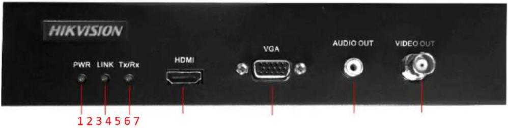
Figure 2-1 Front Panel of DS-6901UDI
Table 2-1 Descripon of DS-6901UDI Front Panel
| No. | LED Indicator & Interface | Description |
| 1 | POWER | Power indicator |
| 2 | LINK | Network conncon indicator |
| 3 | Tx/Rx | Data transming/receiving status indicator |
| 4 | HDMI video output | HDMI output for decoded video |
| 5 | VGA video output | VGA output of decoded video |
| 6 | Audio output | Audio output, 3.5mm connector |
| 7 | Video output | Video output, BNC connector |
● Front Panel of DS-6904/6908UDI
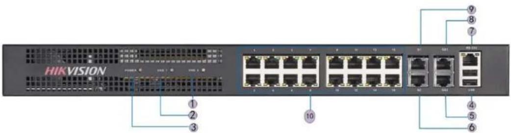
Figure 2-2 Front Panel of DS-6904/6908UDI
Table 2-2 Descripon of DS-6904/6908UDI Front Panel
| LED Indicator & Interface | Connections | |
| 1 | Power | Power indicator |
| 2 | HDD1 | Hard disk 1 indicator (Reserved) |
| 3 | HDD2 | Hard disk 2 indicator (Reserved) |
| 4 | USB | USB 2.0 interface |
| 5 | GE2 | Local management network interface 2 |
| 6 | G2 | 10/100/1000 Mbps Ethernet interface 2 |
| 7 | RS-232 serial interface | Connect to RS-232 devices, e.g., PC etc. |
| 8 | GE1 | Local management network interface |
| 9 | G1 | 10/100/1000 Mbps Ethernet interface |
| 10 | LAN | LAN 10/100 Mbps Ethernet interface |

NOTE
DS-6904UDI provides 4-ch HDMI output interfaces and other interfaces are the same with DS-6908UDI.
● Front Panel of DS-6910/6912/6916UDI
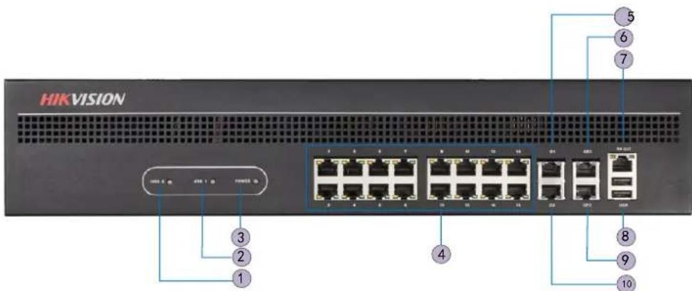
Figure 2-3 Front Panel of DS-6916UDI
Table 2-3 Descripon of DS-6916UDI Front Panel
| LED Indicator & Interface | Connections | |
| 1 | HDD1 | Hard disk 1 indicator (Reserved) |
| 2 | HDD2 | Hard disk 2 indicator (Reserved) |
| 3 | POWER | Power indicator |
| 4 | LAN | 10/100 Mbps Ethernet interface |
| 5 | G1 | 10/100/1000 Mbps Ethernet interface |
| 6 | GE1 | Local management network interface |
| 7 | RS-232 serial interface | Connect to RS-232 devices, e.g., PC etc. |
| 8 | USB | USB 2.0 interface |
| 9 | GE2 | Local management network interface 2 |
| 10 | G2 | 10/100/1000 Mbps Ethernet interface 2 |
2.2 Rear Panel
● Rear Panel of DS-6901UDI
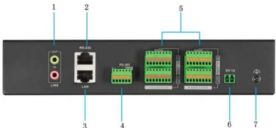
Figure 2-4 Rear Panel of DS-6901UDI
Table 2-5 Descripon of DS-6901UDI Rear Panel
| Interface | Connections | |
| 1 | LINE IN/OUT | Two-way audio input/output, 3.5 mm connector |
| 2 | RS-232 serial interface | Connect to RS-232 devices, e.g., PC. |
| 3 | LAN | 10/100/1000 Mbps Ethernet interface |
| 4 | RS-485 serial interface | Connect to RS-485 devices, e.g., keyboard. |
| 5 | Alarm in | 8 alarm inputs |
| Alarm out | 8 alarm outputs | |
| 6 | Power supply | 12 VDC power input |
| 7 | [WDWR] | GND |
● Rear Panel of DS-6908UDI
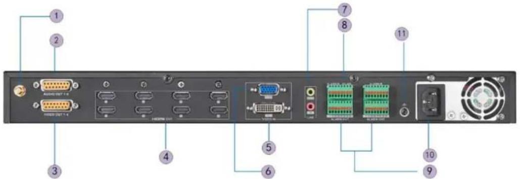
Figure 2-5 Rear Panel of DS-6908UDI
Table 2-6 Descripon of DS-6908UDI
| Interface | Connections | |
| 1 | Wi-Fi | For Wi-Fi conncon |
| 2 | Audio output | BNC connector |
| 3 | Video output | BNC connector |
| 4 | HDMI video output | HDMI output of decoded video |
| 5 | DVI video input | DVI input of decoded video |
| 6 | VGA video input | VGA input of decoded video |
| 7 | LINE IN/OUT | Two-way audio input/output, 3.5mm connector |
| 8 | RS-485 serial interface | Connect to RS-485 devices, e.g., keyboard. |
| 9 | Alarm in | 8 alarm inputs |
| Alarm out | 8 alarm outputs | |
| 10 | Power | Power indicator |
| 11 |  | GND |
● Rear Panel of DS-6916UDI
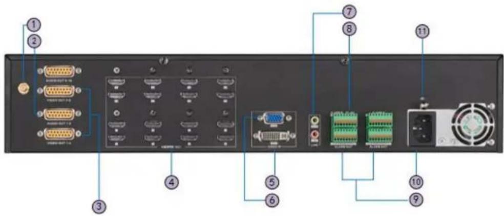
Figure 2-6 Rear Panel of DS-6916UDI
Table 2-7 Descripon of DS-6916UDI Rear Panel
| Interface | Connections | |
| 1 | Wi-Fi | For Wi-Fi conncon |
| 2 | Audio output | BNC connector |
| 3 | Video output | BNC connector |
| 4 | HDMI video output | HDMI output of decoded video |
| 5 | DVI video input | DVI input of decoded video |
| 6 | VGA video input | VGA input of decoded video |
| 7 | LINE IN/OUT | Two-way audio input/output, 3.5mm connector |
| 8 | RS-485 serial interface | Connect to RS-485 devices, e.g., keyboard, etc. |
| 9 | Alarm in | 8 alarm inputs |
| Alarm out | 8 alarm outputs | |
| 10 | Power | Power indicator |
| 11 | GND |

NOTE
DS-6910UDI provides 10 HDMI output interfaces, DS-6912UDI provides 12 HDMI output interfaces and other interfaces are the same with DS-6916UDI.
Chapter 3 Device Activation
Purpose
You are required to acvate the decoder rst by seng a strong password for it before you can use the device. And you can congure the basic network parameters.
Acvaon via Web Browser and Client Soware are all supported.

NOTE
For the rst-me user, the default user name of DS-6900UDI is admin, and the default IP address is 192.0.0.64.
3.1 Activating via SADP Software
SADP soware is used for detecting the online device, acvang the camera, and reseng the password.
Get the SADP soware from the supplied disk or the ocial website, and install the SADP according to the prompts. Follow the steps to acvate the camera.
Step 1 Run the SADP soware to search the online devices.
Step 2 Check the device status from the device list, and select the inactive device.
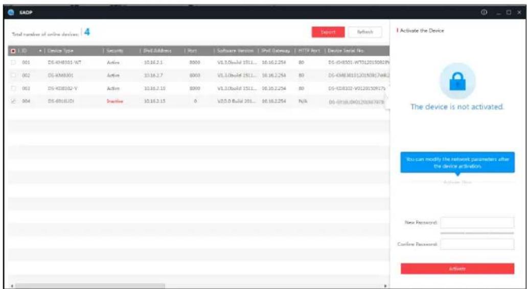
Figure 3-1 SADP Interface
Step 3 Create a password and input it in the password eld, and conrm the password.
Step 4 Click Acvate to acvate the device.

WARNING
STRONG PASSWORD RECOMMENDED—We highly recommend you create a strong password of your own choosing (Using a minimum of 8 characters, including at least three of the following categories: upper case leers, lower case leers, numbers, and special characters.) in order to increase the security of your product. And we recommend you reset your password regularly, especially in the high security system, reseng the password monthly or weekly can beer protect your product.
Step 5 Change the device IP address to the same subnet with your computer by either modifying the IP address manually or checking the checkbox of Enable DHCP.
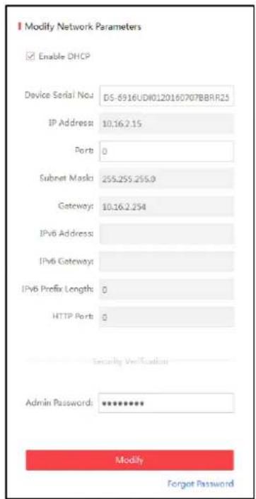
Figure 3-2 Modify the IP Address
Step 6 Input the password and click the Modify buon to acvate your IP address modicaon.
3.2 Activating via Web Browser
Step 1 Power on the decoder, and connect the decoder to the network.
Step 2 Input the IP address into the address bar of the web browser, and click Enter to enter the acvaon interface.
![Activation User Name admin Password ✓ ✓ Strong ✓ Valid password range [8-16]. You can use a combination of numbers, lowercase, uppercase and special character for your password with at least two kinds of them contained. Confirm ●●●●●●●●●●●●● OK](/content/2026/05/812044/images/002939317aa58f604b2e355bd48e3fbdb1b054f19e392b0df27dffbf5a716024.jpg)
Figure 3-3 Acvaon Interface
Step 3 Create a password and input the password into the password eld.

WARNING
STRONG PASSWORD RECOMMENDED—We highly recommend you create a strong password of your own choosing (Using a minimum of 8 characters, including at least three of the following categories: upper case leers, lower case leers, numbers, and special characters.) in order to increase the security of your product. And we recommend you reset your password regularly, especially in the high security system, reseng the password monthly or weekly can beer protect your product.
Step 4 Conrm the password.
Step 5 Click OK to save the password and enter the live view interface.
3.3 Activating via Client Software
The client soware is versale video management soware for mulple kinds of devices.
Get the client soware from the supplied disk or the ocial website, and install the soware according to the prompts. Follow the steps to acvate the camera.
Step 1 Run the client soware.
Step 2 Click the Device Management icon to enter the Device Management interface, as shown in the gure below.
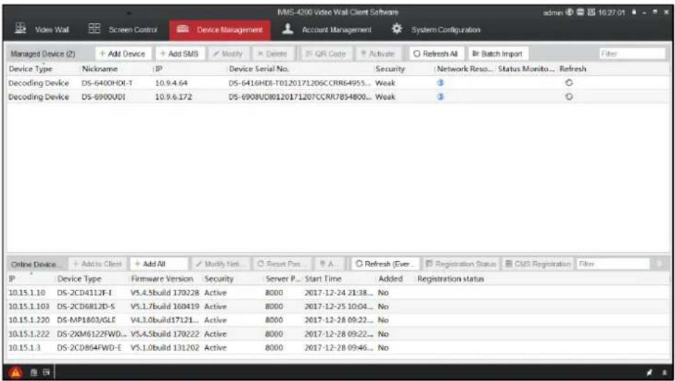
Figure 3-4 Device Management
Step 3 Check the device status from the device list, and select an inactive device.
Step 4 Click the Acvate buon to pop up the Acvaon interface.
Step 5 Create a password and input the password in the password eld, and conrm the password.

WARNING
STRONG PASSWORD RECOMMENDED—We highly recommend you create a strong password of your own choosing (Using a minimum of 8 characters, including at least three of the following categories: upper case leers, lower case leers, numbers, and special characters.) in order to increase the security of your product. And we recommend you reset your password regularly, especially in the high security system, reseng the password monthly or weekly can beer protect your product.
![Activate User Name: admin Password: ••••••••• Strong Valid password range [8-16]. You can use a combination of numbers, lowercase, uppercase and special character for your password with at least two kinds of them contained. Verification: •••••••••• OK Cancel](/content/2026/05/812044/images/bc1dae2ff7be27a3d7b0c53797f28c255cceb8a19e398acaafa807716704e9be.jpg)
Figure 3-5 Acvaon Interface (Client Soware)
Step 6 Click OK buon to start acvaon.
Step 7 Click the Modify Nenfo buon to pop up the Network Parameter Modicaon interface, as shown in the gure below.
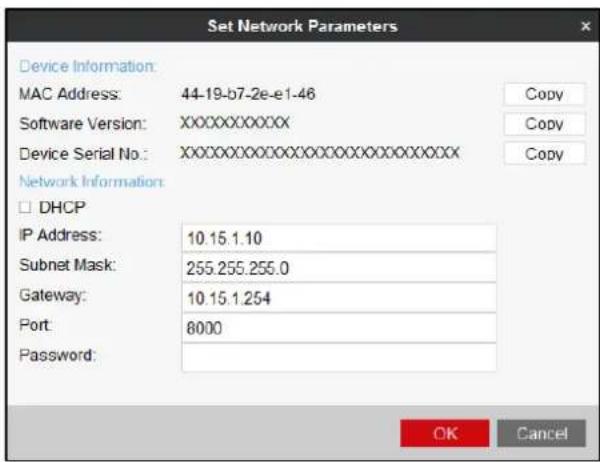
Figure 3-6 Modify the Network Parameters
Step 8 Change the device IP address to the same subnet with your computer by either modifying the IP address manually or checking the DHCP checkbox.
Step 9 Input the password to acvate your IP address modicaon.
Chapter 4 Network Configuration

NOTE
You shall acknowledge that the use of the product with the Internet access might be under network security risks. For avoidance of any network aacks and informaon leakage, please strengthen your own protecon. If the product does not work properly, contact with your dealer or the nearest service center.
Purpose
You shall configure the basic network, and DDNS sengs before other operaons. In this chapter, the network conguraon of the decoder by the Web browser is provided.

NOTE
The tested Web browsers include: IE 8.0+, Chrome 18.0+, Firefox 5.0+, and Safari 5.02+. Step 1 Open the Web browser and input the IP address of Decoder (e.g., hp://192.168.0.0). Step 2 Log in to the device.
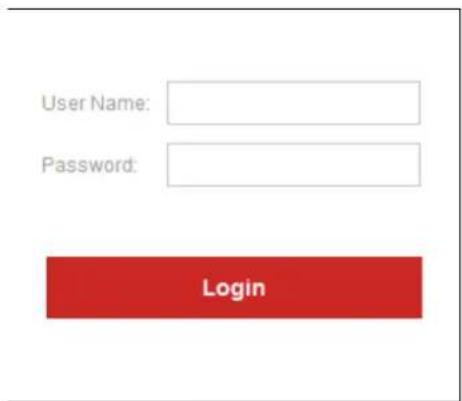
Figure 4-1 Login Interface
- If the device has not been acvated, you need to acve the device rst before login.
![Activation User Name admin Password Strong Valid password range [8-16]. You can use a combination of numbers, lowercase, uppercase and special character for your password with at least two kinds of them contained. Confirm OK](/content/2026/05/812044/images/e722bb65991d326b3b4c7116a7726cb39d35852fd20599d5a2fc8acfdccf9f36.jpg)
Figure 4-2 Acvaon Interface

WARNING
STRONG PASSWORD RECOMMENDED—We highly recommend you create a strong password of your own choosing (Using a minimum of 8 characters, including at least three of the following categories: upper case leers, lower case leers, numbers, and special characters.) in order to increase the security of your product. And we recommend you reset your password regularly, especially in the high security system, reseng the password monthly or weekly can beer protect your product.
- If the device is already acvated, input the user name and password in the login interface, and click the Login buon.
The following interface is shown aer successful login.
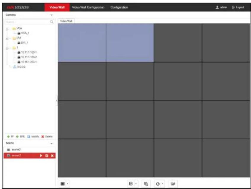
Figure 4-3 Enter Web Page
4.1 Configuring Basic Network Settings
Purpose
You can set the network parameters for the decoder in the parameter conguraon interface.Step 1 Click Conguraon > Network > TCP/IP to enter the general network sengs interface.
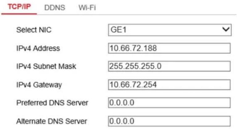

Figure 4-4 Congure Basic Network Sengs
Step 2 Set the network parameters, including the NIC, IP Address, Subnet Mask, Gateway, and DNS Server.

NOTE
The DS-6904/6908/6910/6912/6916UDI provides mulple NICs for selection.
Step 3 Click Save to save the sengs.
4.2 Configuring DDNS Settings
Purpose
If your device is set to use PPPoE as its default network conncon, you may set Dynamic DNS (DDNS) to be used for network access.
Prior registraon with your DDNS Provider is required before conguring the system to use DDNS.
Step 1 Click Conguraon > Network > DDNS to enter the DDNS Sengs interface.
Step 2 Check the Enable DDNS checkbox to enable this funcon.
Step 3 Select DDNS Type. Four different DDNS types are selectable: IPServer, DynDNS, PeanutHull, and NO-IP.
• DynDNS
- Enter Server Address for DynDNS (e.g., members.dyndns.org).
- Enter the User Name and Password registered in the DynDNS website.
- In the Domain text eld, enter the domain obtained from the DynDNS website.
- Click Save to save the sengs.
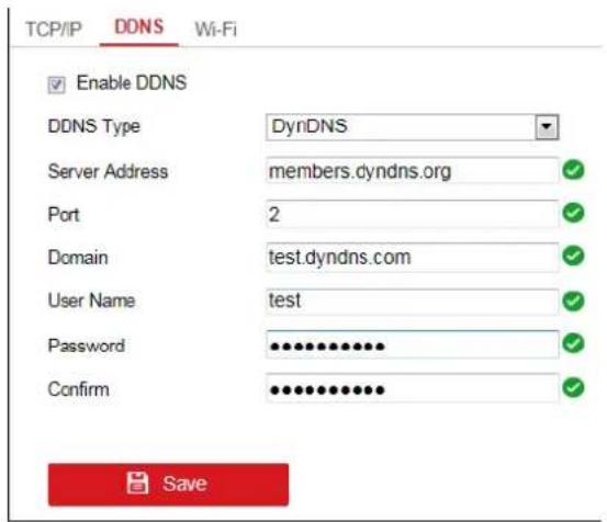
Figure 4-5 DynDNS Sengs
- IPServer
- Enter server address for IPServer.
- Click Save to save the sengs.

NOTE
For the IP Server, you have to apply a stac IP, subnet mask, gateway and primary DNS from the ISP. The Server Address should be entered with the stac IP address of the PC that runs IP Server soware.
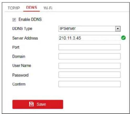
Figure 4-6 IPServer Sengs
- PeanutHull
- Enter User Name and Password obtained from the PeanutHull website.
- Click Save to save the sengs.
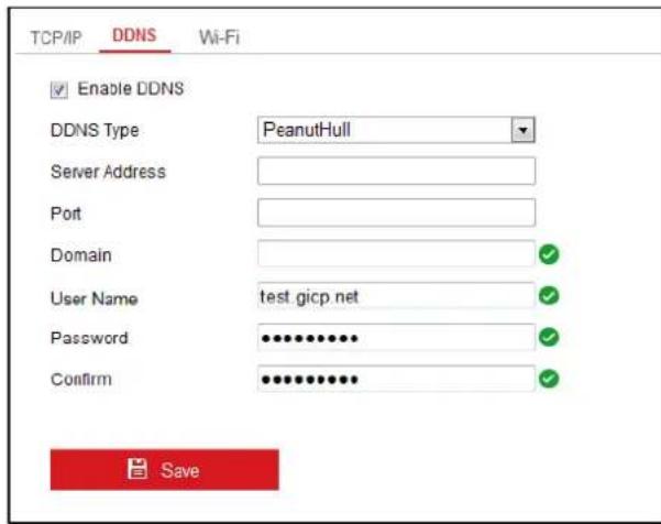
Figure 4-7 PeanutHull Sengs
NO-IP
- Enter Server Address for NO-IP.
- In the Domain text eld, enter the domain obtained from the NO-IP website (www.no-ip.com).
- Enter the User Name and Password registered in the NO-IP website.
- Conrm the password.
- Click Save to save the sengs.
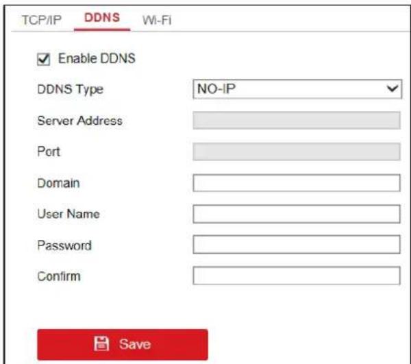
Figure 4-8 NO-IP Sengs
4.3 Configuring Security Control
Purpose
You can disable SSH, SADP, or HTTPS to enhance the access security, e.g., when you are in the untrusted network environment.
Step 1 Go to Conguraon > Security Control.
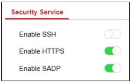
Figure 4-9 Security Service
Step 2 Uncheck Enable SSH, Enable SADP, or Enable HTTPS to disable the services.

NOTE
● By default, SSH is disabled, and SADP and HTTPS are enabled.
- The login user name for SSH is root, and the password is the same with that of the admin.
Chapter 5 Decoding Parameters Configuration
5.1 Configuring Stream Settings
Purpose
The stream conguraon refers to the auto stream switch between main stream and sub-stream.
Step 1 Click Conguraon > Decoding Conguraon > Stream Conguraon to enter stream conguraon interface.
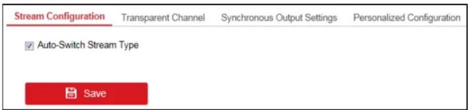
Figure 5-1 Stream Conguraon Interface
Step 2 Check the check box of Auto-Switch Stream Type to enable auto switch between main stream and sub-stream.
Step 3 Click Save buon to save the sengs.

NOTE
When a screen is split into more than 16 windows, the main stream will automatically switch to sub-stream to lower the bandwidth.
5.2 Configuring Transparent Channel
Purpose
The Transparent Channel refers to the transmission channel used for forwarding data between the decoder and the encoder without operang on the data.
Step 1 Click Conguraon > Decoding Conguraon > Transparent Channel to enter transparent channel sengs interface.
| Camera List | Modify | Delete | ||||
| No. | Local Serial Port | Remote Serial Port | IP Address | Port | Connection Status | |
| 1 | RS-232 | 0 0.0.0 | 0 | Not connected | ||
| 2 | RS-232 | 0.0.0.0 | 0 | Not connected | ||
| 3 | RS-232 | 0 0.0.0 | 0 | Not connected | ||
| 4 | RS-232 | 0 0.0.0 | 0 | Not connected | ||
| 5 | RS-232 | 0 0.0.0 | 0 | Not connected | ||
| 6 | RS-232 | 0 0.0.0 | 0 | Not connected | ||
| 7 | RS-232 | 0 0.0.0 | 0 | Not connected | ||
| 8 | RS-232 | 0 0.0.0 | 0 | Not connected | ||
| 9 | RS-232 | 0 0.0.0 | 0 | Not connected | ||
| 10 | RS-232 | 0 0.0.0 | 0 | Not connected | ||
| 11 | RS-232 | 0 0.0.0 | 0 | Not connected | ||
| 12 | RS-232 | 0 0.0.0 | 0 | Not connected | ||
| 13 | RS-232 | 0 0.0.0 | 0 | Not connected | ||
Figure 5-2 Transparent Channel Interface
Step 2 Select a transparent channel from the list to congure.
Step 3 Click Modify to modify the parameters of the selected transparent channel.
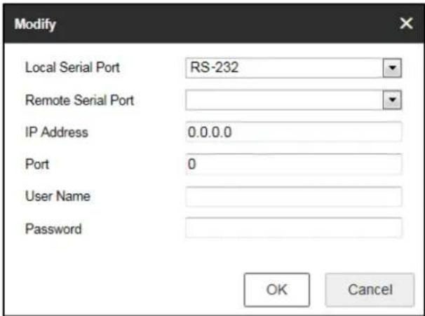
Figure 5-3 Modifying Interface
Step 4 Select the Local Serial Port and the Remote Serial Port to RS-485 or RS-232.
Local Serial Port: The serial port used as the transparent channel by the decoder.
Remote Serial Port: The serial port used as the transparent channel by the encoding device.

NOTE
You can click Delete to delete the selected channel.
5.3 Configuring Synchronous Output Settings
Purpose
All video outputs of the device can be congured to be synchronous.
Step 1 Click Conguraon > Decoding Conguraon > Synchronous Output Sengs to enter the Synchronous Output Sengs interface.

Figure 5-4 Synchronous Output Sengs
Step 2 Click the Enable Sync Out buon to enable the synchronizaon of all outputs. The following message box pops up.
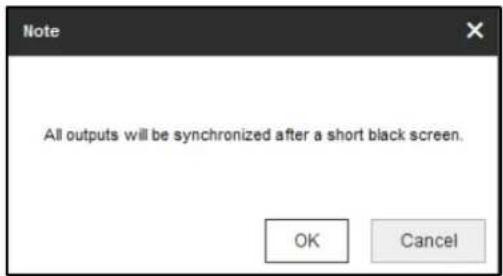
Figure 5-5 Enable Synchronous Output
Step 3 Click OK to conrm the sengs.
5.4 Configuring Personalized Settings
Purpose
You can set the stopped decoding image and failed streaming image for the personalized conguraon.
Step 1 Click Conguraon > Decoding Conguraon > Personalized Conguraon to enter the personalized conguraon interface.
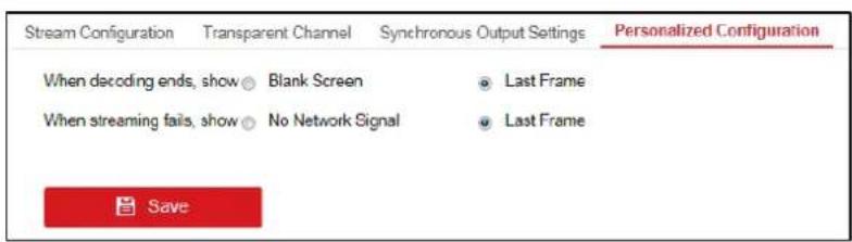
Figure 5-6 Personalized Conguraon
Step 2 Select Blank Screen or Last Frame when decoding ends. If you select Blank Screen, the screen will change blank when the decoding ends. If you select Last Frame, the screen will show the last frame when the decoding ends.
Step 3 Select No Network Signal or Last Frame when streaming fails. If you select No Network Signal, the screen will show the cause of the failure when streaming fails. If you select Last Frame, the screen will show the last frame when streaming fails.
Step 4 Click Save to save the sengs.
Chapter 6 Decoding Operation
6.1 Configuring Encoding Devices
6.1.1 Adding an Encoding Device
Purpose
You can add an encoding device via IP address or URL.
- Adding an Encoding Device via IP Address
Step 1 Click IP to add encoding devices.
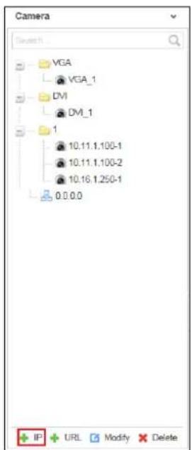
Figure 6-1 Encoding Device List
Step 2 Input Device Name, Type, Port, User Name, Password and Channel Number and select the Transmission Protocol, Area Name, and Device Manufacturer. Decide whether to enable Stream Encrypon and input the encrypon password. Check the checkbox of Get Stream by Stream Media to lower the network load of the device.

NOTE
- You can add device by IP or DDNS. If you select DDNS, you need to enter the domain name and ensure that you have congured the DNS server. For details, see secon 4.1 Conguring Basic Network Sengs.
- If Stream Encrypon is enabled, you need to input the encrypon password so you can remotely watch live videos of encrypted camera streams.
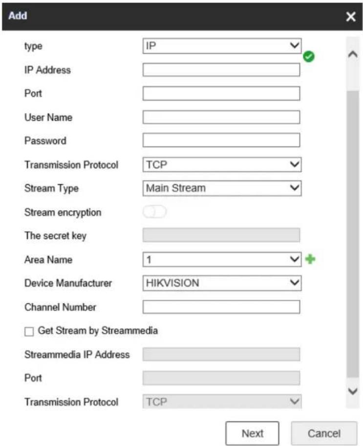
Figure 6-2 Add Device via IP Address
Step 3 (Oponal) You can also click to add a new area and click to save the area.
Step 4 Click Next to select the channel. The channel(s) displayed here depend(s) on the Channel Number you input on the previous page.
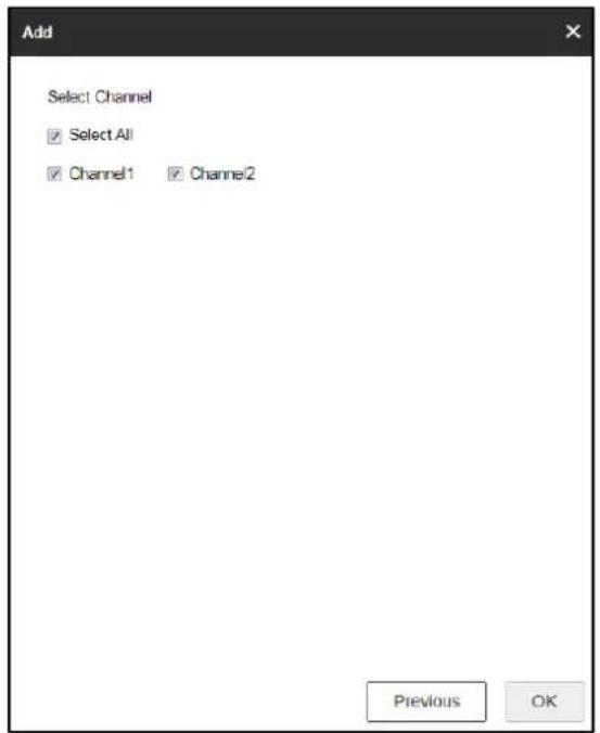
Figure 6-3 Select the Channel
Step 5 Click OK to save the sengs and add the device.
- Adding an Encoding Device via URL
Step 1 Click URL to add encoding devices.
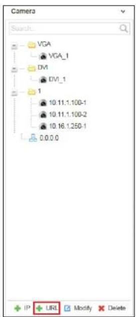
Figure 6-4 Encoding Device List
Step 2 Input the Device Name and URL. Select the Area Name from the dropdown list or click + to add a new area. Decide whether to enable Stream Encrypon and input the encrypon password.

NOTE
● An example of the URL format is as follows:
rtsp://10.9.1.233:554/h264/ch1/main/av_stream/?username=admin?password=hik12345?linkmode=tcp
In the above URL, 10.9.1.233 indicates the device IP, admin indicates the user name, hik12345 indicates the password, and tcp indicates the stream transport protocol. The transport protocol can be set as tcp, udp, and mcast.
- If Stream Encrypon is enabled, you need to input the encrypon password so you can remotely watch live videos of encrypted camera streams.
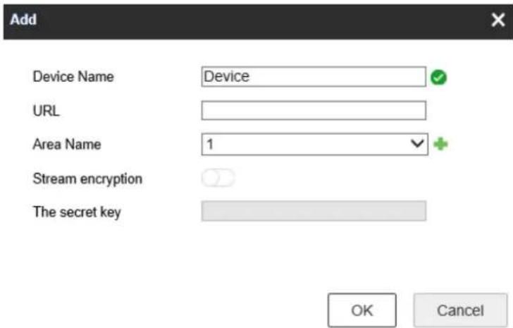
Figure 6-5 Add Device via URL
Step 3 Click OK to save the sengs.
6.1.2 Modifying an Encoding Device
Step 1 Select one area or one encoding device, and click Modify to modify corresponding parameters.
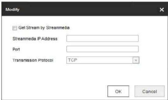
Figure 6-6 Modify Area
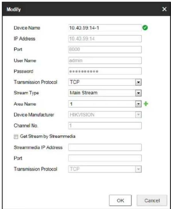
Figure 6-7 Modify Encoding Device
Step 2 Click OK to save the new sengs.
6.1.3 Deleting an Encoding Device
Step 1 Select one area or one encoding device and click Delete to pop up the note interface below.
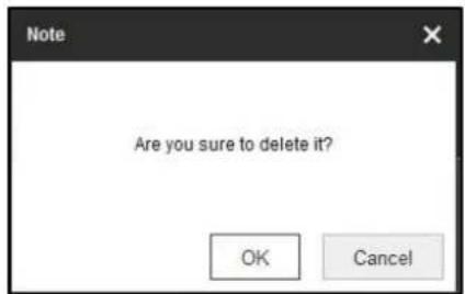
Figure 6-8 Deleng Note
Step 2 Click OK to delete it.
6.2 Configuring Video Wall
Purpose
To realize the display of the decoded video on the video wall, you must set the video wall conguraon rst so as to link the video output with video wall.
Step 1 Click Video Wall Conguraon to enter the corresponding interface.
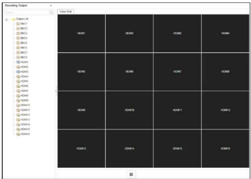
Figure 6-9 Video Wall Conguraon
Step 2 You can use the default video wall layout or click to add a new layout. Input the number of screens in row and column and up to 16 × 20 split screens are available.
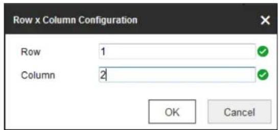
Figure 6-10 Screen Layout Conguraon
Step 3 Click OK to nish the adding of the video wall informaon.
Step 4 Drag the output channels from the le-side list to the display screen.
Step 5 Move the cursor to the window, and the icon ☒automacally appears in the upper-right corner of the window. Click ✗to close the window.
Figure 6-11 Close the Window
6.3 Configuring Decoding Output
Purpose
In the output list, there are two kinds of video output signals, respectively BNC and HDMI. You can congregate the resolution and output mode.
6.3.1 Configuring BNC Output
Step 1 Click Video Wall Conguraon to enter the corresponding interface. Right click one of the BNC signal sources.
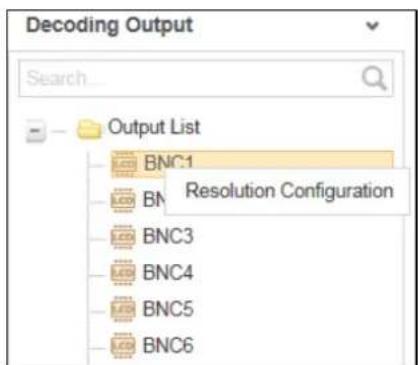
Figure 6-12 BNC Decoding Output
Step 2 Right click one of BNC signal sources and select Resoluon Conguraon to pop up the interface as below.
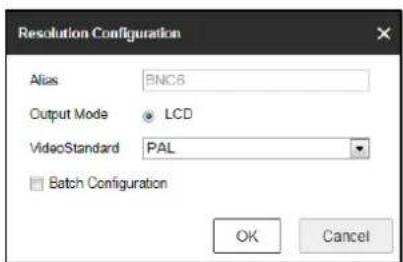
Figure 6-13 Resoluon Conguraon
Step 3 Select the resoluon from the LCD Resoluon drop-down list. PAL and NTSC are selectable.
Step 4 Check the checkbox of Batch Conguraon to set the same configuraon for other outputs with same signal source.
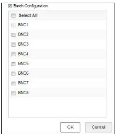
Figure 6-14 Batch Conguraon
Step 5 Click OK to save the sengs.
6.3.2 Configuring HDMI Output
Step 1 Right click one of the HDMI signal sources.
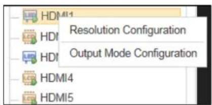
Figure 6-15 HDMI Decoding Output
Step 2 Click Resoluon Conguraon to enter the interface below.
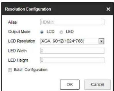
Figure 6-16 Resoluon Conguraon
Step 3 Select the Output Mode and set the corresponding parameters. You can select LCD and LED.
LCD
- Select the Output Mode to LCD.
- Select the resoluon from the LCD Resoluon drop-down list.
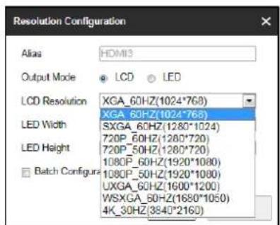
Figure 6-17 Set LCD Resoluon
LED
- Select the Output Mode to LED.
- Input the LED Width and LED Height in the corresponding text elds.
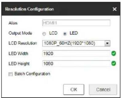
Figure 6-18 Set LED Resoluon

NOTE
● The value of LED width and height cannot exceed the output resolution you select.
- The supported min. value of LED width × height of HDMI output is 288 × 288 and the max. value is 1920 × 1080.
Step 4 Check the checkbox of Batch Conguraon to set the same conguraon for other outputs with same signal source.
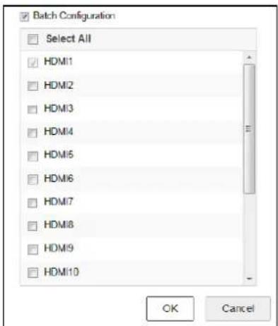
Figure 6-19 Batch Conguraon
Step 5 Click OK to save the sengs.
Step 6 Right click one of the HDMI signal sources and click Output Mode Conguraon to pop up the interface below.
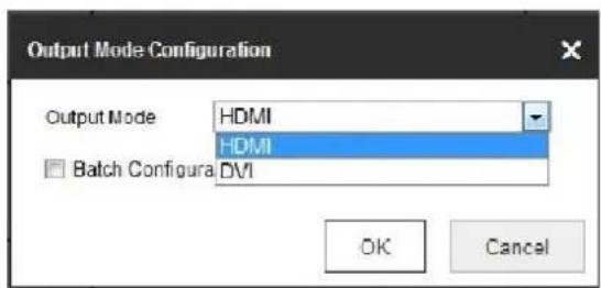
Figure 6-20 Output Mode Conguraon
Step 7 Select the output mode to HDMI or DVI.
Step 8 Check the checkbox of Batch Conguraon to set the same conguraon for other HDMI outputs.
Step 9 Click OK to save the sengs.
6.4 Decoding Video on Video Wall
Purpose
You can decode the video of the encoding devices on the video wall by dragging the channel directly or opening window via coordinate.
6.4.1 Interface Description
Click Video Wall to enter the video wall interface.
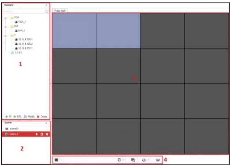
Figure 6-21 Video Wall Interface
Refer to the following gure for the video wall descripon.
Table 6-1 Descripon of Video Wall
| No. | Description |
| 1 | Encoding Device List: The encoding devices added in the Web |
| 2 | Scene: The Web supports up to 8 scenes by default, capable of independent scene conguraon and fast switching. |
| 3 | Video Wall: Video wall operaon interface |
| 4 | Shortcut Toolbar: Select decoding screen layout. Select decoding screen layout. Save the scene Save the scene Delete all windows Delete all windows Refresh all windows Refresh all windows If two decoding windows overlap with each other, click the icon to switch the upper window to the boom. If two decoding windows overlap with each other, click the icon to switch the upper window to the boom. |
6.4.2 Dragging Channels to the Video Wall
Step 1 Drag the channel from the le side list to realize the decoding in the selected window.
You can also drag an area le to the video wall to decode the added encoding devices in the area le on the video wall.

NOTE
- You cannot drag an area le to the video wall across the LCD and LED outputs.
- If there are more than 3 encoding devices in an area, when you drag the area le to the video wall, the note pops up to remind you that no more window can be opened or the total area of layers in single-screen has reached the limit. Only the rst 3 encoding devices in the area le can be decoded on the video wall.
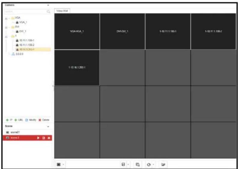
Figure 6-22 Decode the Video on the Wall
Step 2 Select one decoding window and click to set the decoding screen layout. 1/2/4/6/8/9/12/16/25/36 window division modes are available.
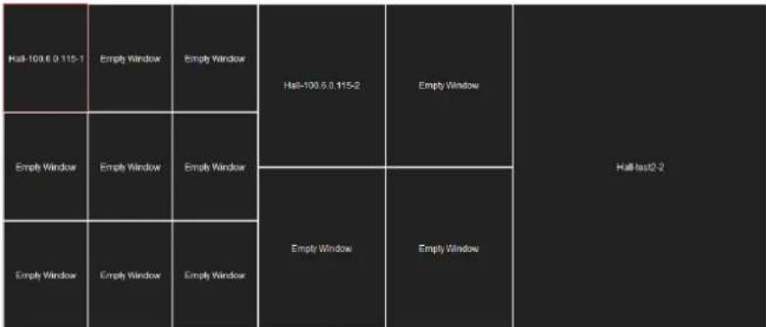
treemap
| Category | Empty Window | Hail-100.6.0.115-1 | Hail-100.6.0.115-2 | |---|---|---|---| | Hail-100.6.0.115-1 | Empty Window | Empty Window | Empty Window | | Empty Window | Empty Window | Empty Window | Empty Window | | Empty Window | Empty Window | Empty Window | Empty Window | Hall-test2.2Figure 6-23 Window Division
6.4.3 Openning Window via Coordinate
Step 1 Select one encoding device and right-click it to pop up the interface below.
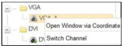
Figure 6-24 Right-Click Menu
Step 2 Click Open Window via Coordinate.
Step 3 Select the Window Opening Mode. LCD and LED are selectable.
- Opening Window via Coordinate for LCD Output
1) Select the Window Opening Mode as LCD.
2) Enter the Le Margin, Right Margin, Width and Height in the corresponding text elds.
3) Click OK to save the setngs.
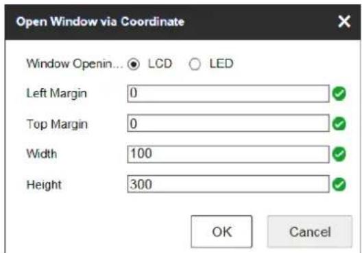
Figure 6-25 Open Window via Coordinate for LCD Output
4) The window will be opened in the LCD area.
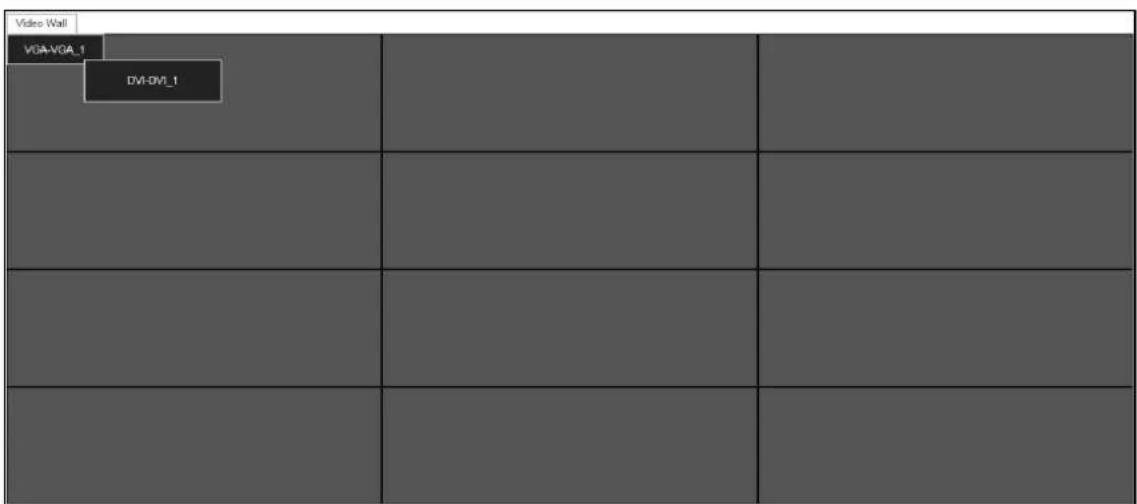
Figure 6-26 Window Opened in LCD Area
● Opening Window via Coordinate for LED Output
1) Select the Window Opening Mode as LED.
2) Select the LED area.
The area number depends on the HDMI decoding output conguraon. For the adjacent HDMI outputs, if the resolution is congured to be LED, and the LED width or height is same, they can be seen as one area. You can refer to Chapter 6.3.2 Conguring HDMI Output.
3) Enter the Le Margin, Right Margin, Width and Height in the corresponding text elds.
4) Click OK to save the setngs.
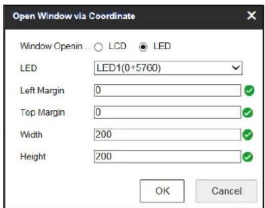
Figure 6-27 Open Window via Coordinate for LED Output
5) The window will be opened in the LED area.
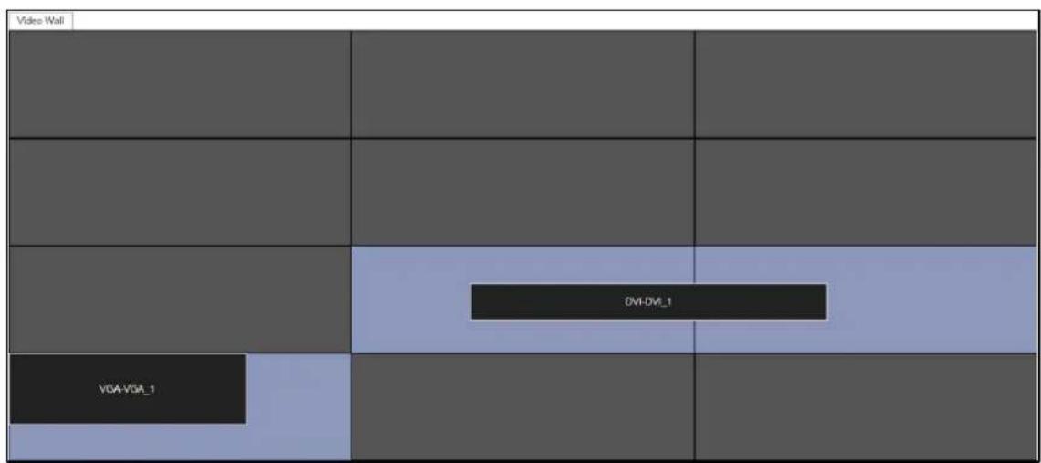
Figure 6-28 Window Opened in LED Area
6.4.4 Managing Decoding
Right-click the selected window and the Decoding Management interface pops up.
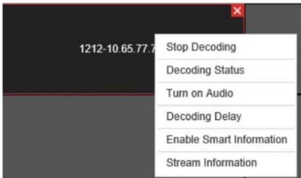
Figure 6-29 Decoding Management
- Stop Decoding
Click the buon to stop decoding.
- Decoding Status
- Click the buon to enter the decoding status interface.
- View the decoding status.
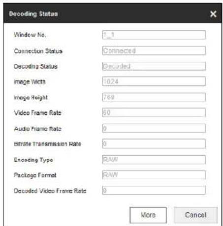
Figure 6-30 Decoding Status
- Click More to check the decoding informaon of each channel.
| Window. | Connection Status | Decoding Status | Image Width | Image Height | Video Frame Rate | Audio Frame Rate | Biterate Transmission. | Encoding Type | Package Format | Decoded Video Fram.. |
| 1_1 | Connected | Decoded | 1290 | 720 | 59 | 0 | 0 | RAW | RAW | 19864 |
| 2_1 | Connected | Decoded | 1290 | 720 | 59 | 0 | 0 | RAW | RAW | 19446 |
| 3_1 | Not connected | Not decoded | 0 | 0 | 0 | 0 | 0 | UNKNOWN | UNKNOWN | 0 |
| 4_1 | Not connected | Not decoded | 0 | 0 | 0 | 0 | 0 | UNKNOWN | UNKNOWN | 0 |
Figure 6-31 Check More Decoding Status Informaon
- Turn on Audio
- Click the buon to enter the interface below.
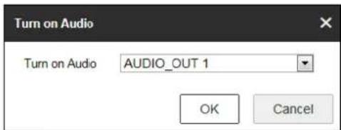
Figure 6-32 Turn on Audio
- Select from the dropdown list to enable the audio in the corresponding window.
- Click OK to save the seings.
- Decoding Delay
- Click the buon to enter the decoding delay interface.
- Select the type of decoding delay. The default mode is the same with medium real time and uency.
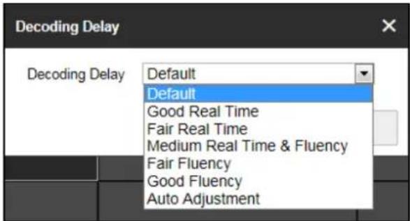
Figure 6-33 Decoding Delay
- Click OK to save the sengs.
● Enable Smart Informaon
- Click the buon to enable smart informaon.
- (Oponal) Click Disable Smart Informaon to disable the funcon.

NOTE
For the normal IP camera, the smart informaon refers to the VCA informaon. For the thermal network camera, the smart informaon refers to the VCA and the temperature, dynamic resource detector and ship detector informaon.
- Stream Informaon
Click the buon to view stream informaon such as host name and transport protocol.
6.4.5 Switching Encoding Channel
Purpose
You can switch the encoding channel to display on the selected decoding window.
Step 1 Select a decoding window and select an encoding channel from the le side list.
Step 2 Click Switch Channel from the right-click menu to switch the selected channel to the decoding window.
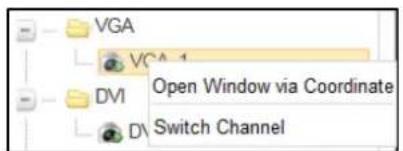
Figure 6-34 Right-Click Menu
6.4.6 Configuring Auto-Switch of Cameras
Purpose
You can enable auto-switch of the added cameras in one area.
Step 1 Select a camera area and click Start Auto-Switch from the right-click menu.
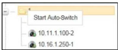
Figure 6-35 Right-Click Menu
Step 2 On the Start Auto-Switch interface, input the Interval for auto-switch.
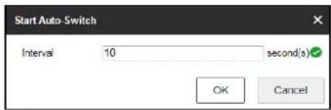
Figure 6-36 Start Auto-Switch
Step 3 Click OK to save the sengs.
6.4.7 Roaming Window
Step 1 Drag one camera from the le side list to the video wall layout to enable decoding in the corresponding window automacally.
Step 2 Drag the decoding window randomly to realize the window roaming on the video wall.
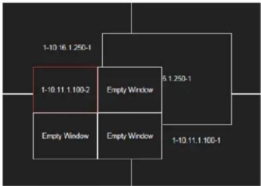
Figure 6-37 Window Roaming
Step 3 Select one of the roaming windows, and click to realize window division in the selected roaming window with 1/2/4/6/8/9/12/16/25/36 available.
Step 4 (Oponal) Generally the selected window is at top by default. Click to place the selected window at boom.

NOTE
- Roaming and uent video cannot be realized in the window with the signal output via BNC interfaces.
● The roaming window cannot cross the output window of dierent resolution. For example, you cannot move the roaming window across the LCD and LED window.
6.4.8 Zooming in/out Roaming Windows
Purpose
You can double click the roaming window to zoom in or out.
● For one roaming window:
Step 1 Double click the roaming window to zoom in. Then the window will occupy the area with the same output.
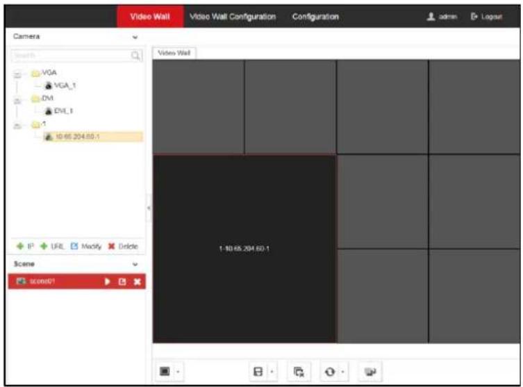
Figure 6-38 Zoom in
Step 2 Double click the window again to zoom out. Then the window will restore to the original size.
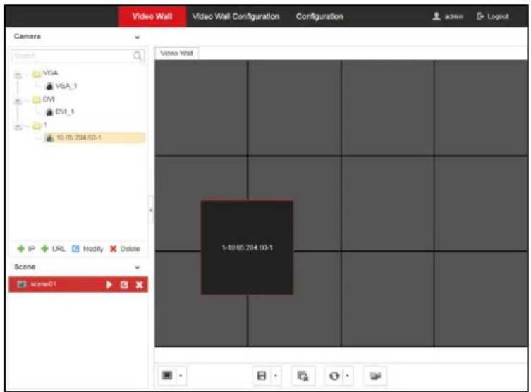
Figure 6-39 Zoom out
● For divided roaming sub-window:
Step 1 Double click the divided roaming sub-window to zoom in. Then the sub-window will occupy the whole window before being divided.
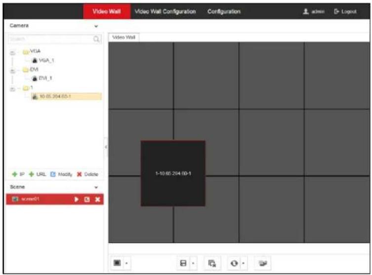
Figure 6-40 Zoom in
Step 2 Double click the divided roaming sub-window again to zoom out. Then the sub-window will restore to the original size.
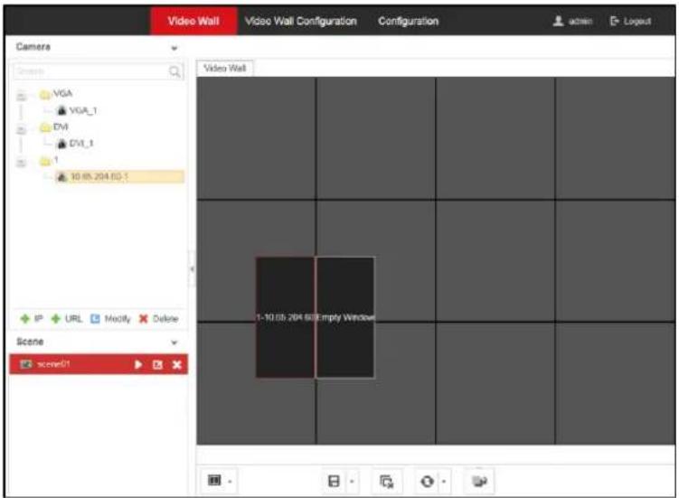
Figure 6-41 Zoom out
6.4.9 Configuring Scene
Purpose
Dierent video wall layouts can be saved as dierent scenes and up to 8 scenes can be added. You can easily view the required live videos on the video wall by calling the scene.
Step 1 In the Video Wall interface drag the channel from the le side list to realize the decoding in the selected window.
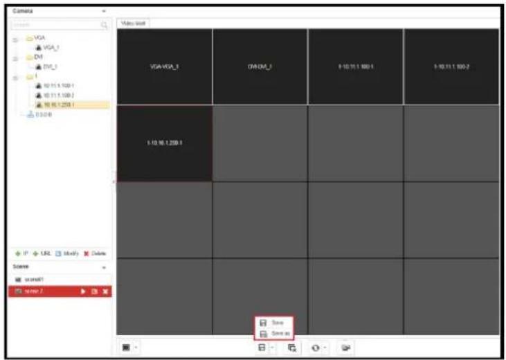
Figure 6-42 Save the Scene
Step 2 Click Save to save the scene directly or click Save as to pop up the following dialog box.
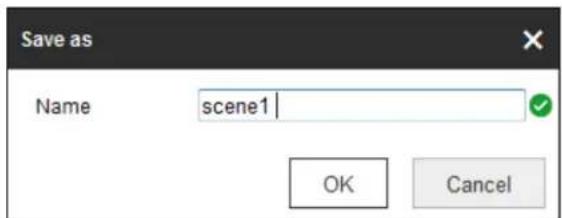
Figure 6-43 Save as Interface
Step 3 Input the Name and click OK to save the scene.
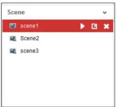
Figure 6-44 Scene List
Step 4 Select one of the scenes you have congured. Click to call the scene.
Step 5 (Oponal) You can also click to rename the scene, or click to delete the scene.
Chapter 7 User Management
Purpose
You can add, modify, delete, and set the permissions of the user accounts on the User Management interface.
Step 1 Click Conguraon > System > User Management to enter the user management interface.
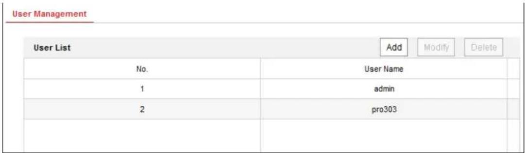
Figure 7-1 Congure User Account
Step 2 You can add, modify or delete the user account, as well as congure operang permissions for each user account.
![Add User Name example 1 Admin Password ••••••••••• Password •••••••••• Strong Valid password range [3-16]. You can use a combination of numbers, lowercase, uppercase and special character for your password with at least two kinds of them contained. Confirm ••••••••• ✓ Select All ✓ Remote Parameter Settings ✓ Remote Status and Log View ✓ Remote Upgrade ✓ Remote Shutdown / Reboot ✓ Remote Two-way Audio ✓ Remote Serial Port Control ✓ Remote Alarm Upcading ✓ Remote Playback ✓ Remote PTZ Control OK Cancel](/content/2026/05/812044/images/f7c0b385c1937933f01b0f8c896132cf0eed178020cbdc4085b7a9205fcec8be.jpg)
Figure 7-2 Add User Account and Set Permissions

NOTE
- Up to 32 user accounts can be added including the admin.
- For the admin user, only the password can be modified.
- You must input the admin password if you want to modify the user account except the admin.

WARNING
STRONG PASSWORD RECOMMENDED—We highly recommend you create a strong password of your own choosing (Using a minimum of 8 characters, including at least three of the following categories: upper case leers, lower case leers, numbers, and special characters.) in order to increase the security of your product. And we recommend you reset your password regularly, especially in the high security system, reseng the password monthly or weekly can beer protect your product.
Chapter 8 System Configuration
8.1 Checking Device Information
Purpose
You can check the informaon of the device in the device informaon interface, such as the Physical Address, Device Type, Device Serial No., Firmware Version, Decoding Version, Web Version, Plugin Version, etc., and modify the Device Name.
Step 1 Click Conguraon > System > System Sengs > Basic Informaon.
Step 2 (Oponal) Modify Device Name.
The default device name is Embedded mulDecoder. If you want to modify the device name to the model of the device, enter Embedded mulDecoder + # + device model in the text eld.
Step 3 View other device informaon.

NOTE
The descripon about the decoder conguraon and operaon by web browser below is based on the rmware, decoding, web and plugin version shown in the following gure.
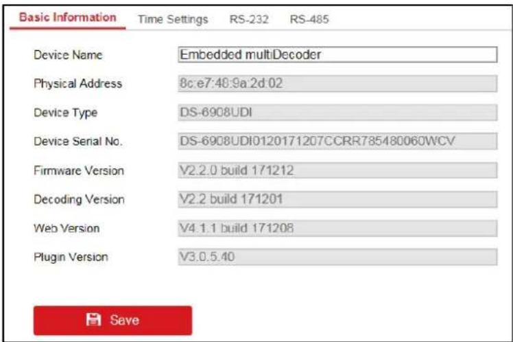
Figure 8-1 Check Device Informaon
8.2 Configuring Time Settings
Purpose
You can set the me for the decoder in the Time Sengs interface.
Step 1 Click Conguraon > System Seings > Time Sengs to enter the following interface:
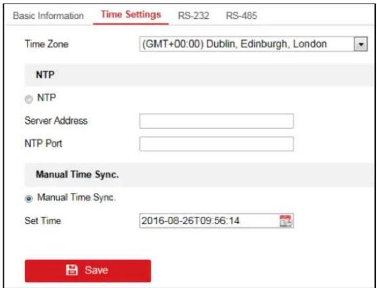
Figure 8-2 Congure Time Sengs
Step 2 Congure the me synchronizaon by NTP server or manually.
● Conguring Time Synchronizaon by NTP Server
A Network Time Protocol (NTP) Server can be congured on your device to ensure the accuracy of system date/me.
If the device is connected to a Dynamic Host Conguraon Protocol (DHCP) network that has me server properes congured, the camera will synchronize automatically with the me server.
Enable the NTP funcon by selecng the radio buon, and congure the following sengs:
NTP Server: IP address of NTP server.
NTP Port: Port of NTP server.
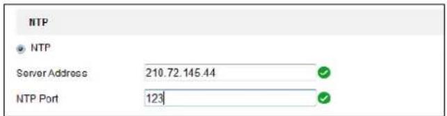
Figure 8-3 Congure Time by NTP

NOTE
If the device is connected to a public network, you should use a NTP server that has a me synchronizaon funcon, such as the server at the Naonal Time Center (IP Address:
210.72.145.44). If the device is set up in a more customized network, NTP soware can be used to establish a NTP server used for me synchronizaon.
● Conguring Time Synchronizaon Manually
Enable the Manual Time Sync. funcon by selecng the radio buon and then click icon to set the system me from the pop-up calendar.
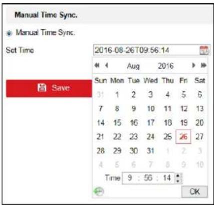
Figure 8-4 Congure Time Manually
Step 3 Select the me zone that is closest to the device's locaon from the drop-down list.
Step 4 Click Save to save the sengs.
8.3 Configuring RS-232 Serial Port
Step 1 Click Conguraon > System Seings > RS-232 to enter the following interface:
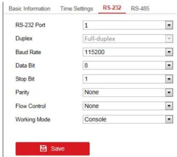
Figure 8-5 Congure RS-232 Sengs
Step 2 Congure the RS-232 parameters, including the baud rate, data bit, stop bit and parity type.
Step 3 Select the Operang Mode of RS-232 as Console or Transparent Channel.
Console: Use the RS-232 serial port for debugging the decoder.
Transparent Channel: Use the RS-232 serial port as the transparent channel.
Step 4 Click Save to save the sengs.
8.4 Configure RS-485 Serial Port
Step 1 Click Conguraon > System Sengs > RS-485 to enter the following interface.
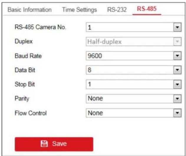
Figure 8-6 Congure RS-485 Setngs
Step 2 Congure the RS-485 parameters, including the baud rate, data bit, stop bit and parity type.
Step 3 Click Save to save the sengs.
Chapter 9 System Maintenance
Purpose
You can click Conguraon > System > Maintenance to perform configuraon les import/export, reboot, upgrade, and default operaons.
9.1 Importing Configuration Files
Purpose
The conguraon les of the device can be imported from the local device, which maintains convenient parameters conguraon.
Step 1 Enter the parameters import interface.
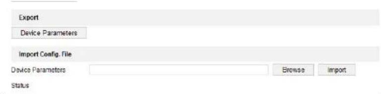
Figure 9-1 Import Conguraon File
Step 2 Click Browse to select the le from the local directory and then click the Import buon to import a conguraon le. Click Device Parameters to export parameters.
9.2 Exporting Configuration Files
Purpose
The conguraon les of the device can be exported to the local device, which maintains convenient parameters conguraon.
Step 1 Enter the parameters export interface.
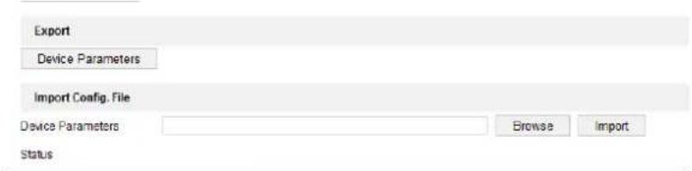
Figure 9-2 Export Conguraon File
Step 2 Click Device Parameters to export parameters.
9.3 Upgrading the Device
Step 1 Enter the Upgrade interface.
Step 2 Click Browse to search the upgrading les.
Step 3 Click Upgrade to upgrade it.

Figure 9-3 Upgrade the Device

NOTE
- When logging in to the device for the rst me, install the plug-in according to the prompt on the screen.
● The device will restart aer compleng the upgrade.
9.4 Restoring the Default Settings
Step 1 Enter the Default Sengs interface.
Step 2 Click Default to restore the completed factory sengs of the decoder.
Or click Restore to restore a part of the factory seings of the decoder.

Figure 9-4 Restore Default Sengs
9.5 Rebooting the Device
Step 1 Enter the Reboot Device interface.
Step 2 Click Reboot to reboot the device.
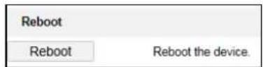
Figure 9-5 Reboot the Device
Chapter 10 Decoder Configuration and Operation by Client Software
Run the disk of iVMS-4200 Video Wall Client Soware, and double click the icon to install it in your PC. In this chapter, the basic procedure of operang the decoder by the soware is described.
10.1 Interface Description
The following gure shows the main interface aer accessing to the soware.
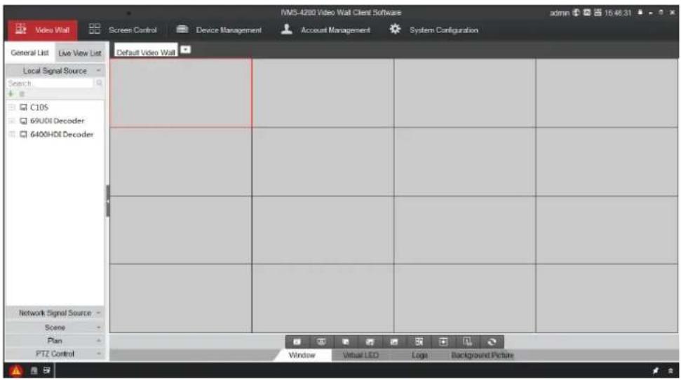
Figure 10-1 Main Interface
Refer to the following table for the descripon of the decoding toolbar on the boom of the main interface.
Table 10-1 Decoding Toolbar
| Icon | Name | Description |
 | Start/Stop Live View | Start/Stop live view of all the windows. |
 | Start/Stop All Decoding | Start/Stop decoding all signal sources and cameras. |
 | Close All Windows | Close all the windows displayed on the video wall. |
 | Start All VCA Decoding | Start VCA decoding for all live view signals. Once started, the VCAinformaon can be viewed in live view. |
| Stop All VCA Decoding | Stop VCA decoding for all live view signals. | |
| Open Window | Draw a window according to your need. The size and posion of the window are adjustable. | |
| Open Window via Coordinate | Open a window by inpung X-coordinate, Y-coordinate, width and height. | |
| Show Window ID | Click it to show the window ID. | |
| Refresh | Refresh the video wall status. |

NOTE
The soware is capable of many funcons for controlling and managing many devices. In this manual, only the operaon related to the decoder is introduced.
10.2 Adding an Encoding/Decoding Device
Step 1 Click Device Management tab to enter the Device Management interface.
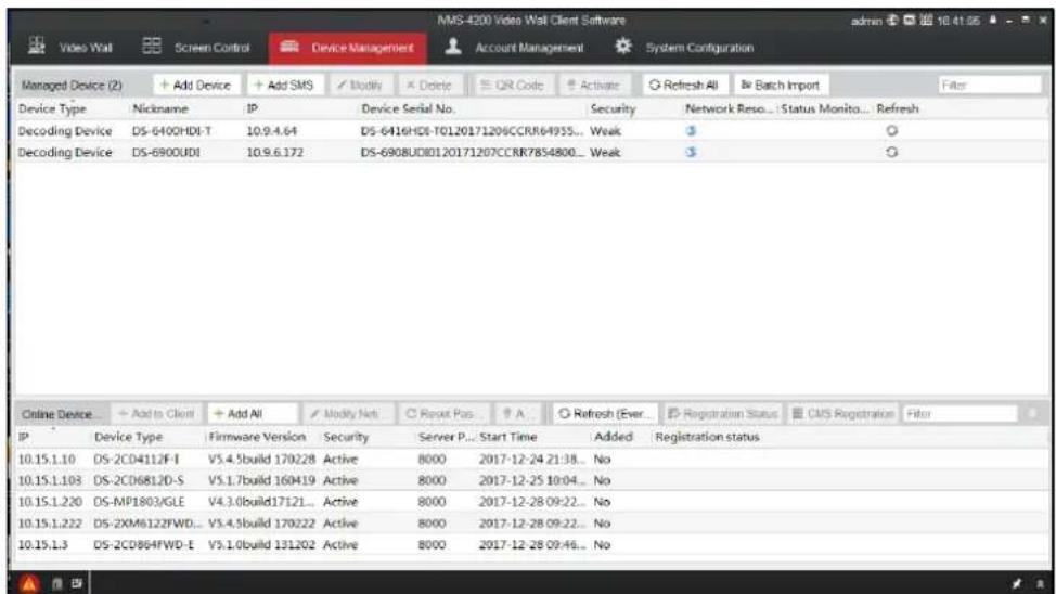
Figure 10-2 Device Management Interface
Step 2 Click Add Device and you can add device manually by means of IP address/domain, IP segment, and URL.

NOTE
An example of the URL format is as follows:
rtsp://10.9.1.233:554/h264/ch1/main/av_stream/?username=admin?password=hik12345?linkmode=tcp
In the above URL, 10.9.1.233 indicates the device IP, admin indicates the user name, hik12345 indicates the password, and tcp indicates the stream transport protocol.
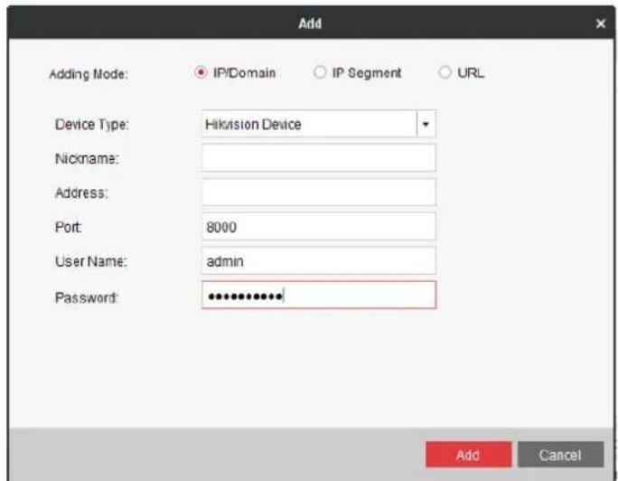
Figure 10-3 Add Device by IP/Domain
Step 3 You can add device by detecting the online devices. The acve online decoding devices in the same local subnet with the soware are displayed on the list. Select the decoder and click Add to Client to add the decoder.
| Online Device (3) | + Add to Client | + Add All | ✓ Modify RefInfo | ○ Reset Password | ✓ Active | ○ Refresh (Every 80s) | Filter |
| IP | Device Type | Firmware Version | Security | Server Port | Start Time | Added | |
| 10.15.1.233 | DS-6454HD- | V2.3.0 build 150904 | Active | 8000 | 2015-06-18 08:55:58 | No | |
| 10.15.1.240 | DS-ZDF7209-A | V5.3.0build 150321 | Active | 8000 | 2015-06-10 19:28:41 | No | |
| 10.15.1.22 | TS-5012-F | V4.1.0build 150910 | Active | 8000 | 2015-06-19 13:40:27 | No | |
| 10.15.1.221 | IDS-ZDF7284-A | V5.2.3build 140928 | Active | 8000 | 2015-06-18 15:51:18 | No | |
| 10.15.1.69 | DS-KM5301 | V1.1.0build 150963 | Active | 8000 | 2011-06-04 14:14:54 | No |
Figure 10-4 Add Device by Detecng the Online Device
The successfully added encoding/decoding device can be viewed in the list.

Figure 10-5 List of Added Devices
10.3 Configuring Video Wall
10.3.1 Adding a Video Wall
Step 1 Click Video Wall tab to enter the Video Wall interface.
Step 2 You can use the default video wall layout or click ▼ and select Add Video Wall to enter the Add Video Wall interface.

NOTE
You can modify the default video wall, but not allowed to delete it.
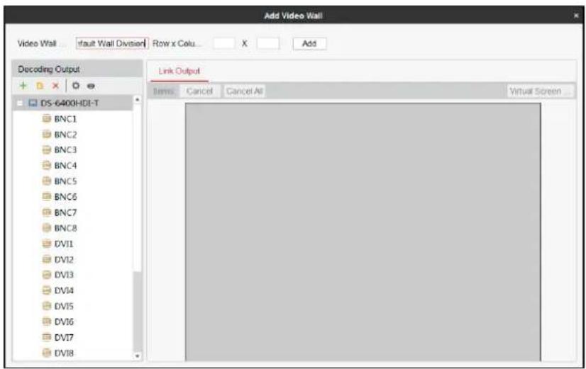
Figure 10-6 Add Video Wall
Step 3 Input the Video Wall Name, and the number of windows in row and column text elds.
Step 4 Click Add to add the video wall.

NOTE
- Up to 5 video walls can be added to the client soware.
- The range of the row number is between 1 and 16, and column number between 1 and 20.
Step 5 Drag the output channels from the le side list to link the decoding output to the video wall.
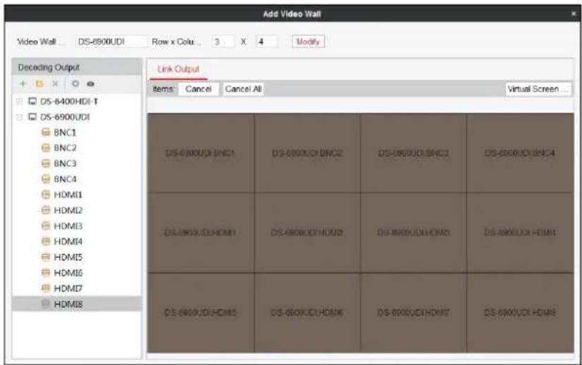
Figure 10-7 Link Decoding Output to Video Wall
Step 6 (Oponal) You can select a linked display window and click Cancel to cancel the linkage, or click Cancel All to cancel all the linked windows.
10.3.2 Modifying a Video Wall
Step 1 Click Modify Video Wall to enter the Modify Video Wall interface.
Step 2 Edit the layout, name and decoding outputs of the current video wall.
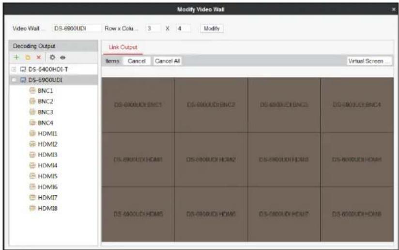
Figure 10-8 Modify Video Wall
10.3.3 Deleting a Video Wall
Step 1 Select Delete Video Wall and the informaon dialog box pops up.
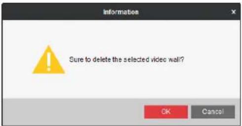
Figure 10-9 Delete Video Wall
Step 2 Click OK to delete the selected video wall.
10.3.4 Configuring Virtual Screen
Purpose:
Video wall layout is restricted by the physical screen and in pracce, one physical screen usually displays more than one signal source. Virtual screen layout allows one physical screen to display mulple signal sources and get rid of the restricon of physical screen.
Step 1 On the Video Wall interface, click ▼ and select Modify Video Wall to enter the Modify Video Wall interface.
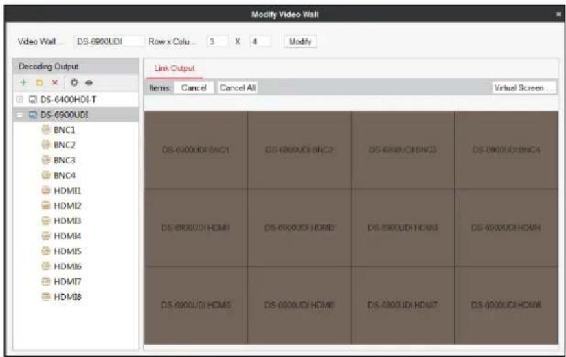
Figure 10-10 Modify Video Wall
Step 2 Select the output area for adding virtual screen.
Step 3 Click Virtual Screen Cong to expand the Virtual Screen Conguraon menu.
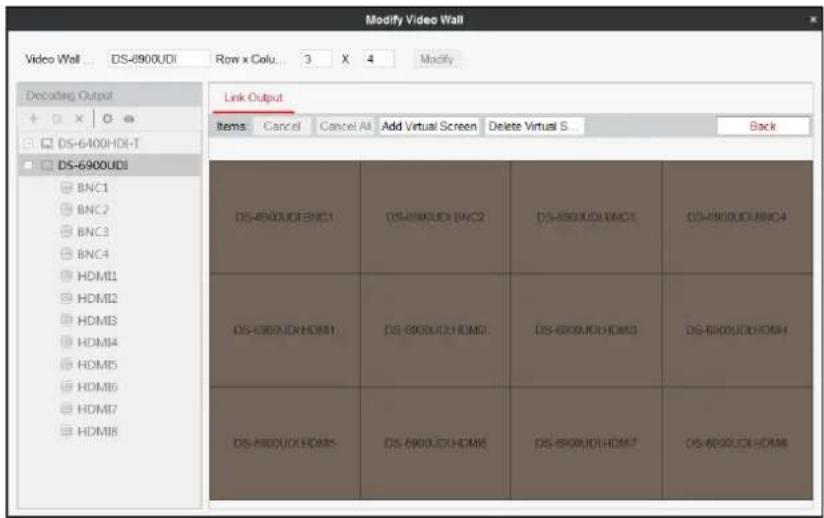
Figure 10-11 Congure Virtual Screen
Step 4 Select the window(s) you want to add virtual screen.

NOTE
You cannot add virtual screen across the LCD and LED areas.
Step 5 Click Add Virtual Screen to enter Congure Virtual Screen interface.
- Select a virtual screen mode from ☐ and input the row and column number.

NOTE
For the mode, the row number ranges from 1 to 16 and column number ranges from 1 to 20. For modes such as , the row number ranges from 2 to 16 and the column number ranges from 2 to 20. For modes such as , the row number ranges from 2 to 16 and the column number ranges from 3 to 20.
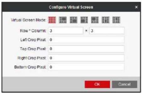
Figure 10-12 Congure Virtual Screen
-
Input the Le Crop Pixel, Top Crop Pixel, Right Crop Pixel and Boom Crop Pixel in the corresponding text elds.
-
Click OK to save the settings and the doed line in grey constitutes the virtual screen division.
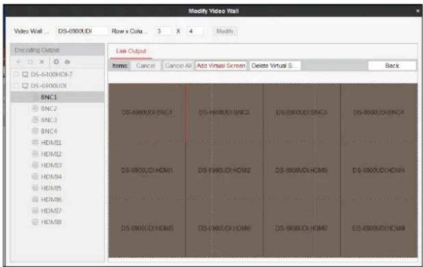
Figure 10-13 Added Virtual Screen
Step 6 (Oponal) Select the congured virtual screen area and click Delete Virtual Screen to delete it.
Step 7 On the Video Wall interface, drag a signal source to the window, and you can view the live view in the virtual video wall layout.
| DS-100001(HOM) | DS-100002(HOM) | DS-100003(HOM) | DS-100004(HOM) |
| DS-100005(HOM) | DS-100006(HOM) | DS-100007(HOM) | DS-100008(HOM) |
| DS-10001(HOM) | DS-100012(HOM) | DS-100013(HOM) | DS-100014(HOM) |
| DS-100019(HOM) | DS-10002(HOM) | DS-10002(HOM) | DS-10002(HOM) |
Figure 10-14 Live View in Virtual Screen
10.4 Configuring Decoding Parameters
Purpose
You can congregate what the screen show when decoding ends and streaming fails, enable auto-switch of sub-stream, and set sub-window size on the Add/Modify Video Wall interface.
Step 1 On the Add/Modify Video Wall interface, select the added decoder and click to enter the General Parameters Conguraon of Video Wall interface.
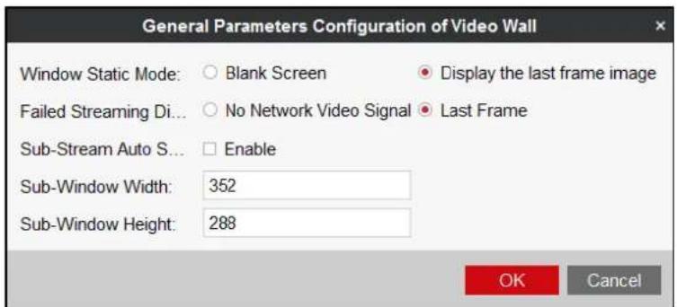
Figure 10-15 General Parameters Conguraon of Video Wall
Step 2 Select Blank Screen or Display the last frame image for Window Static Mode. If you select Blank Screen, the screen will change blank when the decoding ends. If you select Display the last frame image, the screen will show the last frame when the decoding ends.
Step 3 Select No Network Video Signal or Last Frame for Failed Streaming Display Mode. If you select No Network Video Signal, the screen will show no signal when streaming fails. If you select Last Frame, the screen will show the last frame when streaming fails.
Step 4 (Oponal) Check Enable of Sub-Stream Auto Switch to enable the funcon.
Step 5 Enter Sub-Window Width and Sub-Window Height. The width and height range from 1 to 640.
Step 6 Click OK to save the sengs.
10.5 Configuring Decoding Output
Purpose
You can set the output type and resolution of BNC and HDMI decoding outputs on the Add/Modify Video Wall interface.
10.5.1 Configuring BNC Output
Step 1 On the Add/Modify Video Wall interface, select a BNC decoding output and click to enter the Modify Output interface.
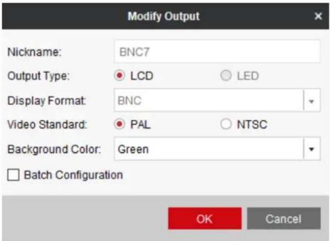
Figure 10-16 Modify BNC Output
Step 2 Select the Output Type and set the corresponding parameters. Only LCD output type can be congured.
Step 3 Select the Video Standard. PAL and NTSC are selectable.
Step 4 Set Background Color for the output. Eight colors are available and you can set a custom color.

NOTE
If you set a background color for an output, the other two linked outputs are set as the same background color. BNC1, HDMI1, and HDMI2 are linked, BNC2, HDMI3, and HDMI4 are linked etc.
Step 5 Check Batch Conguraon to set the same conguraon for other outputs with same signal source.
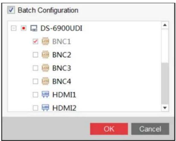
Figure 10-17 Batch Conguraon
Step 6 Click OK to save the sengs.
10.5.2 Configuring HDMI Output
Step 1 On the Add/Modify Video Wall interface, select a HDMI decoding output and click to enter the Modify Output interface.
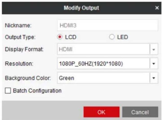
Figure 10-18 Modify HDMI Output
Step 2 Select the Output Type and set the corresponding parameters. You can select LCD and LED.
LCD
- Select the Output Type to LCD.
- Select the Resoluon from the drop-down list.
- Set Background Color for the output. Eight colors are available and you can set a custom color.
LED
- Select the Output Type to LED.
- Input the Width × Height in the corresponding text elds.
- Set Background Color for the output. Eight colors are available and you can set a custom color.
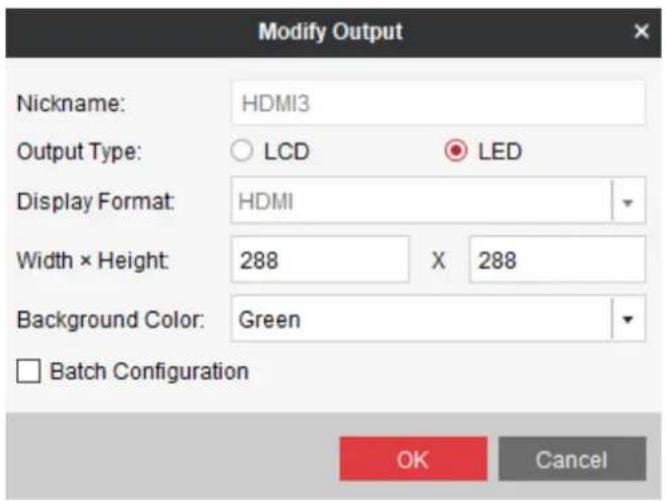
Figure 10-19 Set LED Resoluon

NOTE
● The value of LED width and height cannot exceed the output resolution.
- The supported min. value of LED width × height of HDMI output is 288 × 288 and the max. value is 1920 × 1080.
- If you set a background color for an output, the other two linked outputs are set as the same background color. BNC1, HDMI1, and HDMI2 are linked, BNC2, HDMI3, and HDMI4 are linked etc.
Step 3 Check the checkbox of Batch Conguraon to set the same conguraon for other outputs with same signal source.
Step 4 Click OK to save the sengs.
10.6 Operating Decoding
Purpose
Aer the sengs of the encoding device, decoding device and video wall, the video stream from the encoding devices can be decoded and displayed on the video wall.

NOTE
Aer enabling decoding and displaying, the video from the encoding devices can be displayed on the video wall. And the real-me live view is shown on the physical video wall.
10.6.1 Dragging Channels to the Video Wall
Step 1 Enter the Video Wall interface.
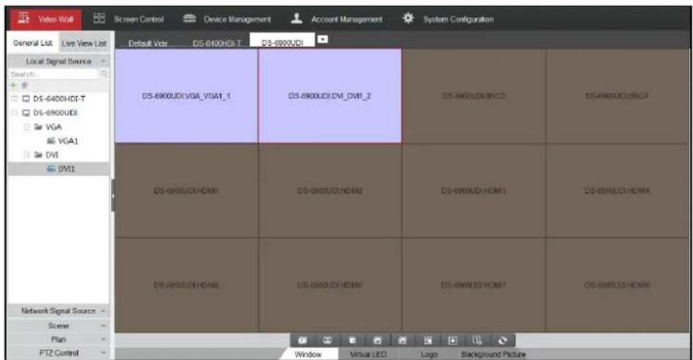
Figure 10-20 Video Wall Interface
Step 2 Drag the camera from the le side camera list to the display window of video wall. The video stream from the camera will be decoded and displayed on the video wall.
You can also select a decoding window and then double click a camera to decode and display the video. You can also hold the Ctrl or Shi key to select mulple cameras and then drag them to the video wall.

NOTE
You can click on the lower part of the interface to stop decoding of all the windows.
10.6.2 Opening Window for Non-LED Screen
Purpose
On the non-LED screen, you are allowed to open the window via coordinate.
Step 1 Enter the Video Wall interface, select the non-LED screen and click the buon the window via coordinate.

open
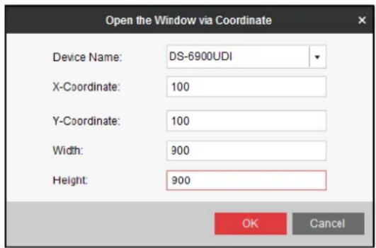
Figure 10-21 Open Window via Coordinate (1)
Step 2 Select the Device Name from the drop down list, and input the X-Coordinate, Y-Coordinate, Width and Height.
Step 3 Click OK to save the settings and the opened window will be displayed on the video wall.

NOTE
- You cannot open the window via coordinate across both the non-LED and LED screens.
● The X-coordinate and Y-coordinate are relative output channel coordinates.
10.6.3 Opening Window for LED Screen
Purpose
On the LED screen you are allowed to open the window via coordinate.
Step 1 Enter the Video Wall interface, select the LED screen and click the buon to open the window via coordinate.
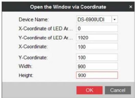
Figure 10-22 Open the Window via Coordinate (2)
Step 2 Select the Device Name from the drop down list, and input the X-Coordinate, Y-Coordinate, Width and Height.
Step 3 Click OK to save the sengs and the opened window will be displayed on the video wall.

NOTE
- You cannot open the window via coordinate across both the non-LED and LED screens.
● You cannot edit the X-Coordinate of LED Area and Y-Coordinate of LED Area.
● The X-coordinate and Y-coordinate are relave output channel coordinates.
10.6.4 Managing Decoding
Step 1 Right-click on a playing window to acvate the decoding management menu as shown below.

NOTE
The menu diers depending on the devices.
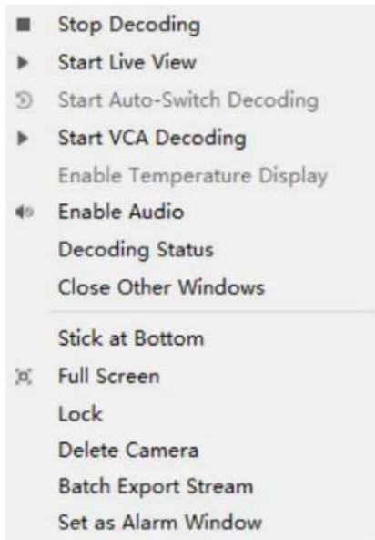
Figure 10-23 Right-click Menu
Step 2 Congure the following parameters.
- Start/Stop Decoding: Start/stop the decoding.
- Start/Stop Live View: Start/stop the live view of the decoded video. The smart information can be displayed in live view.
- Start/Pause Auto-Switch Decoding: Start/pause auto-switch decoding. This funcon is only supported by decoder.
- Start/Stop VCA Decoding: Start/stop VCA decoding.
● Enable Audio: Turn on/off the audio of the decoding video.
● Decoding Status: View the status of the decoding channel, like decoding status and stream type. - Close Other Windows: Click it to close other decoding windows.
- Sck at Boom: Generally the selected window is at top by default. Click Sck at Boom to place the selected window at boom.
● Full Screen: Click it to set the decoding window in full screen. - Lock/Unlock: Click Lock to lock the window. The locked decoding window is unable to do any operaon.
● Batch Export Stream: Record and export a segment of stream of one or mulple cameras to your local PC. A maximum of 16 cameras are supported at a me. - Set as Alarm Window: Display the video triggered by event or alarm input on video wall.
- Screen Control: Enter screen control when the RSC server is added. Please refer to Chapter 10.8 for details.
10.6.5 Configuring Auto-Switch Decoding
Purpose
Auto-switch decoding refers to you can congregate mulple video streams in a video output and the dwell me in switching video streams.
Step 1 Drag a camera group to the display window of the video wall.
Step 2 Click to set the dwell me for the auto-switch decoding and click to start auto-switch decoding. You can view the auto-switch decoding on the physical video wall. You can click to stop auto-switch decoding.
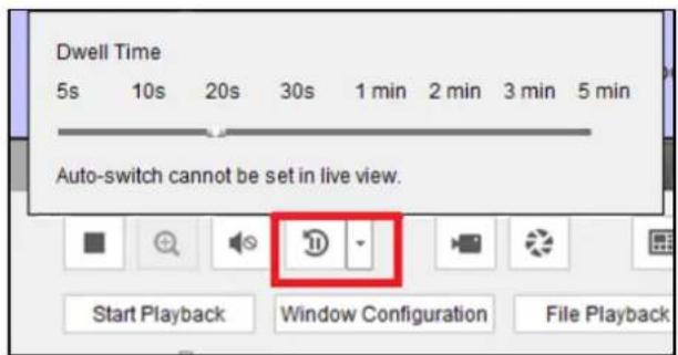
Figure 10-24 Auto-Switch Decoding
10.6.6 PTZ Control

NOTE
This secon is only applicable to the decoded cameras supporting PTZ control.
Step 1 Click PTZ Control to expand the PTZ control panel.
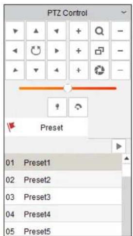
Figure 10-25 PTZ Control Panel
Step 2 Click the direconal and funconal buons to set the preset.
10.6.7 Playback
Purpose
The video le is supported to be played back on the video wall.

NOTE
Playback funcon is only supported by decoder.
Step 1 Drag the camera on the le-side list to the display window of video wall, or you can open a window if supported.
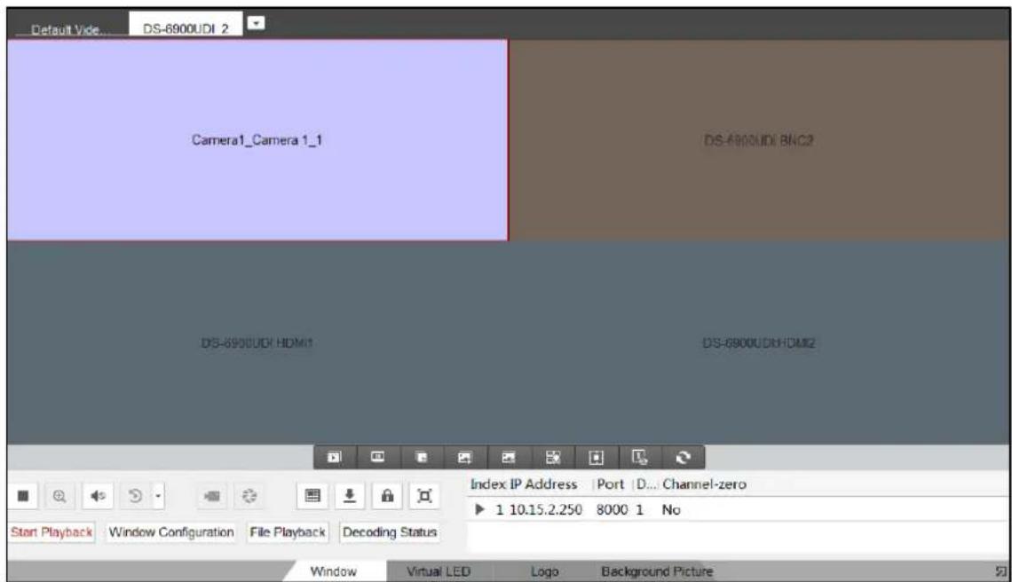
Figure 10-26 Video Wall
Step 2 Click Window at the boom to unfold more conguraon and operaon toolbar.
Step 3 Click Start Playback to start searching the video les of the camera.

Figure 10-27 Playback Interface
Step 4 If the record le is of current day, the video le can be played back automacally. If not, you can click to show the date and click More Search Condions to specify more condions, and click Search to nd the video le.
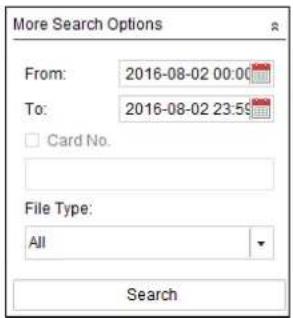
Figure 10-28 Search Record File
The following icons are available for controlling the playback.
Table 10-2 Playback Toolbar
| Icon | Function |
 | Pause/Start the playback |
 | Delete View |
 | Slow Forward |
| [CK58] | Fast Forward |
 | Start/Stop Clipping |
 | Capture |
10.6.8 Configuring Scene
Step 1 Click Scene to expand the scene interface.
Step 2 You can click to add a new scene, click to edit the name for the scene, click to delete the scene and click to save the scene.

NOTE
Up to 8 scenes can be added.
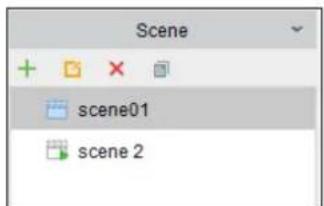
Figure 10-29 Scene List
10.6.9 Configuring Window
● Conguring Window Division Mode
Purpose
You can set the window division mode of the decoding window.
Step 1 Drag a camera from the le-side list to the display window of the video wall, or you can open a window.
Step 2 Click to expand the menu.
Step 3 Click to select the window division mode. 1/2/4/6/8/9/12/16/25/36 modes are selectable.
- Zooming in/out Roaming Windows
You can double click the roaming window to zoom in or out. Refer to Chapter 6.4.8 Zooming in/out Roaming Windows for reference.
• Conguring Window Parameters
Purpose
You can set the window as the alarm window to display the video triggered by event or alarm input on the video wall. You can also set the decoding delay and image parameters.
Step 4 Drag the camera from the le-side list to the display window of the video wall, or you can open a window if supported.
Step 5 Click Window Conguraon to pop up the conguraon dialog box.
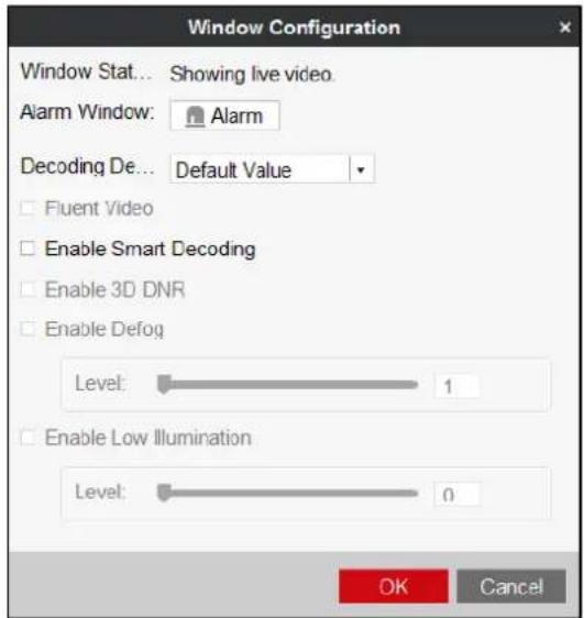
Figure 10-30 Window Conguraon
Step 6 Congure the parameters as needed. The window status shows the current status of the selected window.
- Alarm Window: Display the video triggered by the event or alarm input on the selected window of the video wall.
● Decoding Delay: Set the delay status of the decoding according to the actual needs.

NOTE
Funcons like Fluent Video, 3D DNR, Defog, and Low Illuminaon are not supported by DS-6900UDI.
10.7 Decoding Thermal Network Camera
Purpose
The thermal network camera can be connected to the decoder and you can realize live view and playback, and decode the video including the temperature or re point informaon on the video wall.
10.7.1 Configuring the Thermal Network Camera Parameters
Purpose
You can congregate the corresponding parameters of thermal network camera via the Web browser rst before decoding it on the video wall.
Configuring Temperature Measurement
Step 1 Congure the VCA resource type.
- Log in to the camera via the Web browser.
- Click Conguraon > Advanced Conguraon > System > VCA Resource Type to enter the VCA Resource Type conguraon interface.
- Select Temperature Measurement and Behavior Analysis as the VCA Resource Type.
- Click Save to save the sengs.
Step 2 Congure temperature measurement.
- Click Conguraon > Advanced Conguraon > Temperature Measurement > Temperature Measurement Conguraon to enter the Temperature Measurement conguraon interface.
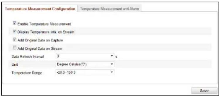
Figure 10-31 Temperature Measurement Conguraon
-
Check the checkboxes of the interface to set the temperature measurement conguraons.
-
Enable Temperature Measurement: Check the checkbox to enable temperature measurement funcon.
- Display Temperature Info. on Stream: Check the checkbox to display temperature informaon in live view.
- Add Original Data on Capture: Check the checkbox to add original data on capture.
-
Add Original Data on Stream: Check the checkbox to add original data on stream.
-
Select the Data Refresh Interval from 1s to 5s.
- Select the Unit to display temperature with Degree Celsius (°C)/Degree Fahrenheit (°F)/Degree Kelvin (K).
- Congure the Temperature Range.
- Click Save to save the sengs.
Step 3 Congure the temperature measurement and alarm.
- Click Conguraon > Advanced Conguraon > Temperature Measurement > Temperature Measurement and Alarm to enter the Temperature Measurement and Alarm conguraon interface.
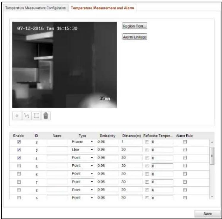
Figure 10-32 Temperature Measurement and Alarm
- Set the alarm rule: Select a temperature measurement rule from the rule list and congure the parameters.
● Name: You can customize the rule name.
● Type: Select point, line, or frame as rule type.
● Emissivity: Set the emissivity of your target. The emissivity of each object is dierent.
● Distance (m): The straight-line distance between the target and the device.
- Reeve Temperature: If there is any target with high emissivity in the scene, check the checkbox and set the reeve temperature to correct the temperature. If no such target exists, uncheck the checkbox.
- Click in the list to show the alarm rule interface.
- Alarm Rule: The alarm rule varies according to dierent types. The rule is to compare the temperature informaon of two selected regions. For targets set by frame, the rules include: Max. Temperature is Higher than, Max. Temperature is Lower than, Min. Temperature is Higher than, Min. Temperature is Lower than, Average Temperature is Higher than, Average Temperature is Lower than, Temperature Dherence is Higher than, and Temperature Dherence is Lower than. For targets set by line, the rules include Max. Temperature, Min. Temperature, and Average Temperature. For targets set by point, the rules are disguished by Average Temperature.
● Pre-Alarm Temperature and Alarm Temperature: Set the pre-alarm temperature and alarm temperature. The device sends pre-alarm when its rule temperature exceeds pre-alarm temperature and sends alarm when its rule temperature exceeds alarm temperature.
- Tolerance Temperature: Set the tolerance temperature and the device judges whether the triggered alarm stops until the device temperature/temperature difference is lower than rule temperature by tolerance temperature. For example, set tolerance temperature as 3°C, set alarm temperature as 55°C, and set pre-alarm temperature as 50°C. The device sends pre-alarm when its temperature reaches 50°C and it alarms when its temperature reaches 55°C and only when the device temperature is lower than 52°C will the alarm be cancelled.
- Draw the Target Region. Select the rule and draw the corresponding frame/line/point. Click to draw the point. Click to draw the line. Click to draw the frame.
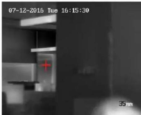
Figure 10-33 Draw Point
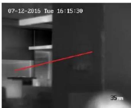
Figure 10-34 Draw Line
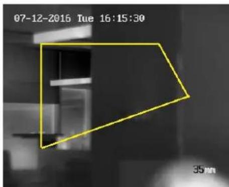
Figure 10-35 Draw Frame
- Set Temperature Dherence Alarm. Click Temperature Dherence Alarm to enter the temperature dherence alarm interface, up to four temperature dherence alarms can be set.

NOTE
Temperature Dherence Alarm is only applicable to the targets set by frame.
- Set Alarm Linkage. Click Alarm Linkage to enter the alarm linkage interface and set the linkage methods.
- Click Save to save the sengs.
Step 4 Congure the local parameters to display the temperature informaon on the live view interface.
- Click Conguraon > Local Conguraon to enter the Local Conguraon interface.
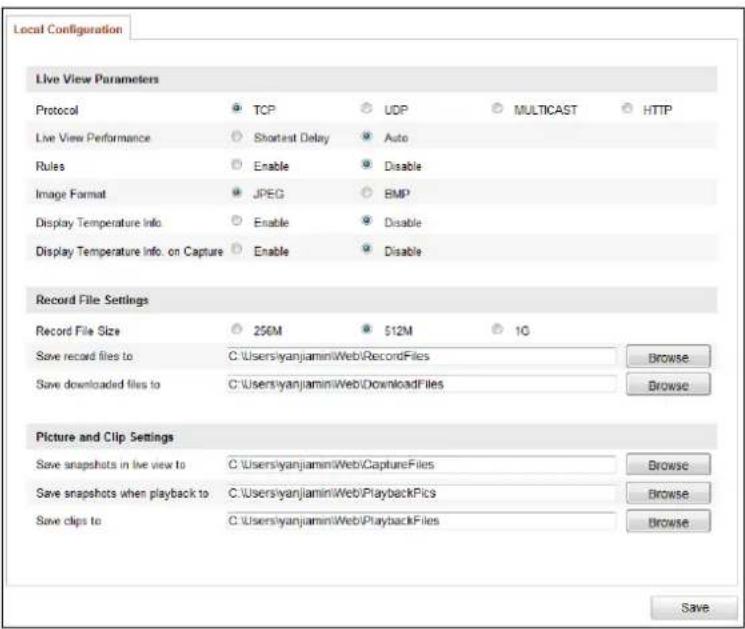
Figure 10-36 Local Conguraon
- In the Live View Parameters secon, select the Enable radio buon of Display Temperature Info. on Stream to display the temperature informaon on the live view interface.
- Click Save to save the sengs and then you can view the posion of the congured point, line and frame, the ID and temperature informaon on the live view interface.
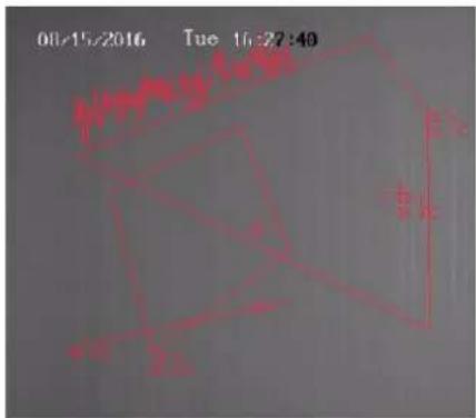
Figure 10-37 Live View
Configuring Dynamic Fire Source Detection
Step 1 Congure the VCA resource type.
- Log in to the camera via the Web browser.
- Click Conguraon > Advanced Conguraon > System > VCA Resource Type to enter the VCA Resource Type conguraon interface.
- Select Dynamic Fire Source Detecon as the VCA Resource Type.
- Click Save to save the sengs and the device will reboot to take the sengs into eect.

NOTE
For the VCA resource type, only one type can be congured. For example, if you select Temperature Measurement and Behavior Analysis as the VCA resource type, you cannot set Dynamic Fire Source Detecon.
Step 2 Congure dynamic re source detecon parameters.
- Click Conguraon > Advanced Conguraon > Smart Event > Dynamic Fire Source Detecon to enter the Dynamic Fire Source Detecon conguraon interface.
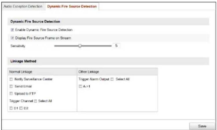
Figure 10-38 Dynamic Fire Source Detecon
- Check the checkbox of Enable Dynamic Fire Source Detecon to enable the funcon.
- (Oponal) Check the checkbox of Display Fire Source Frame on Stream to display a red frame around the re source on stream when re occurs.
- You can slide the cursor to adjust the Sensitivity degree of dynamic re source detecon from 1 to 10. The bigger the number is, the more sensitive the detectng would be.
- Check the checkbox to select the Linkage Method taken for the alarm input.
- Click Save to save the sengs.
Step 3 Congure the local parameters to display re point distance, display highest temperature, locate highest temperature point or frame re point on the live view interface.
- Click Conguraon > Local Conguraon to enter the Local Conguraon interface.
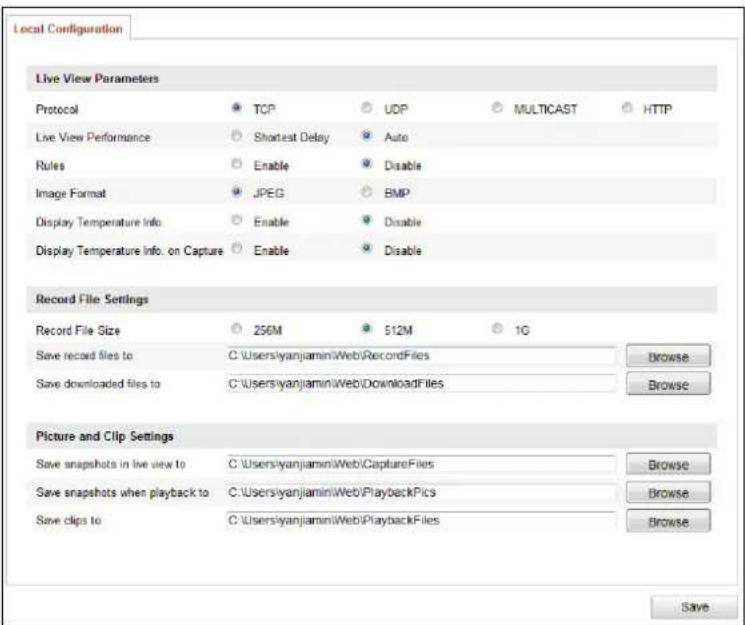
Figure 10-39 Local Conguraon
- In the Live View Parameters secon, check the checkbox aer Fire Point to enable the funcons required. Display Fire Point Distance, Display Highest Temperature, Locate Highest Temperature Point and Frame Fire Point are selectable.
- Click Save to save the sengs and then you can view the re point distance, highest temperature, highest temperature point or re point frame in the live view if re point is detected.
Configuring Ship Detection
Step 1 Enter Conguraon > Advanced Conguraon > System > VCA Resource Type to select Ship Detecon as the VCA Resource Type.
Step 2 Click Conguraon > Advanced Conguraon > Smart Event > Ship Detecon to enter the Ship Detecon interface.
Step 3 Check the checkbox of Enable Ship Detecon to enable the funcon.
Step 4 Check the checkbox of Display Detecon Frame on Video to display the frame and alarm line on stream.
Step 5 Input the device height in the textbox as the height of device above the water level.
Step 6 Draw the ship detecon area and the alarm lines.
- Click Draw Area buon. Click the mouse on the live view image to draw a ship detection area and right-click to nish drawing. The alarm will be uploaded when ship is detected in this area.
- Click Draw Alarm Line buon. Click the mouse on the live view image to draw an alarm line and right-click to nish drawing. The device alarms and counts the ship number when ships are detected in the area and the ship informaon will be displayed on the right.

NOTE
Make sure the alarm line is longer than the width of ship detecon area.
- Click Recount to start counting the ships detected in the area aerwards.
Step 7 Check the checkbox to select the linkage method taken for the alarm input.
Step 8 Click Save to save the sengs.
Configuring VCA
Step 1 Congure the live view parameters to enable rules.
- Click Conguraon > Local Conguraon to enter the Local Conguraon interface.
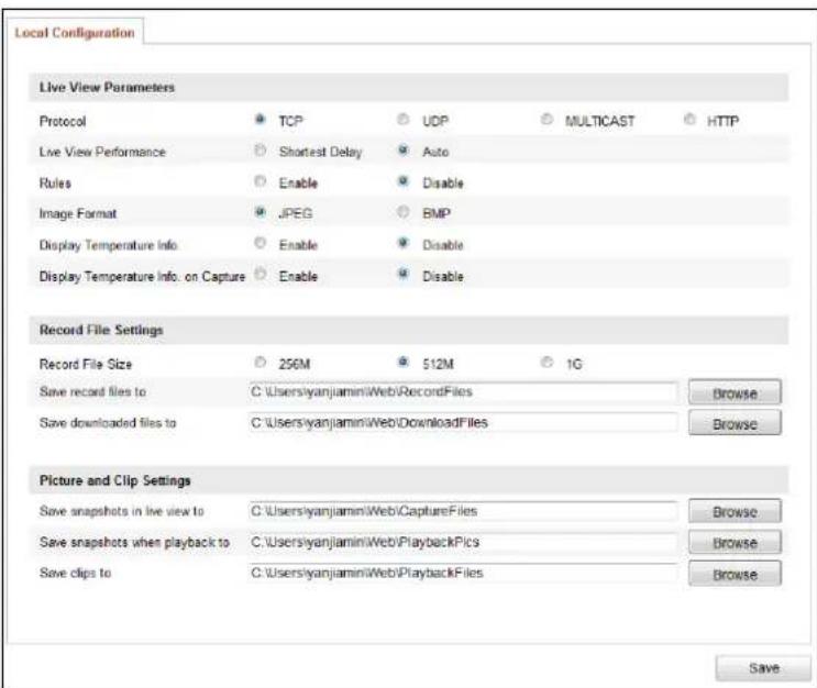
Figure 10-40 Local Conguraon
- On the Live View Parameters secon, select the Enable radio buon aer Rules to display the colored marks when the moon detecon, face detecon, or intrusion detecon is triggered. E.g., enabled as the rules are, and the face detecon is enabled as well, when a face is detected, it will be marked with a green rectangle on the live view.
Step 2 Congure the VCA informaon.
- Click Conguraon > VCA Conguraon > VCA Info. to enter the VCA Informaon interface.
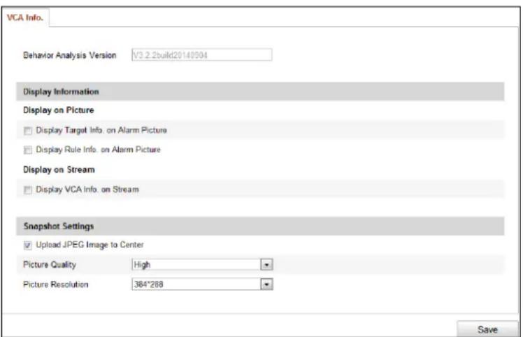
Figure 10-41 VCA Informaon
-
On the Display Informaon secon, check the checkboxes to enable corresponding displays.
-
Display Target info. on Alarm Picture: There will be a frame on the target on the uploaded alarm picture if the checkbox is checked.
- Display Rule info. on Alarm Picture: The captured target and the congured area will be framed on the alarm picture.
- Display VCA info. on Stream: The green frames will be displayed on the target if in a live view or playback.
Step 3 Congure the rules for VCA. Refer to the User Manual of Thermal Network Camera for the specific operaons.
10.7.2 Decoding Thermal Network Camera on the Video Wall
Step 1 Add the thermal network camera to the video wall client soware.
Step 2 On the Video Wall interface, drag the added thermal network camera to the video wall.
Step 3 Click to start live view and you can view the corresponding informaon on the live view interface.
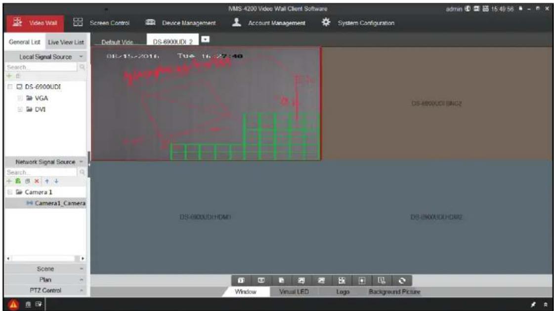
Figure 10-42 Decode Thermal Camera on the Video Wall

NOTE
- If VCA is enabled for the thermal network camera, the decoder can analyze the VCA behavior, mark the moving target and track it. You can view the VCA informaon marked in the green frames in the live view. If the rule congured for the thermal network camera is broken, the alarm will be triggered.
- If temperature measurement is enabled, you can view the posion of the congured point, line and frame, the ID, and temperature informaon in the live view.
- If re point detecon is enabled and there is a re point detected, you can view the congured re point distance, highest temperature, highest temperature point and re point frame in the live view.
- If ship detecon is enabled and there is a ship detected, you can view the congured frames and alarm line in the live view.
Step 4 (Oponal) You can click Window tab on the boom of the interface and click Start Playback to start playing back the camera. Refer to Chapter 7.5.7 Playback for reference. The temperature measurement, re source detecon, ship detecon and VCA informaon can be played back.
Step 5 (Oponal) You can click 📄 or click Stop VCA Decoding from the right-click menu to stop VCA decoding of the thermal network camera.
10.8 Controlling Remote Screen
Purpose
Installed with the RSC Server, it allows you to show your PC screen on the video wall. Follow the following procedure to conjure the RSC server and get your screen shown on the video wall.
10.8.1 Configuring the RSC Server
Step 1 Install the RSE Server, which enables the PC screen to be displayed on the video wall, and
double-click RS - server un it.
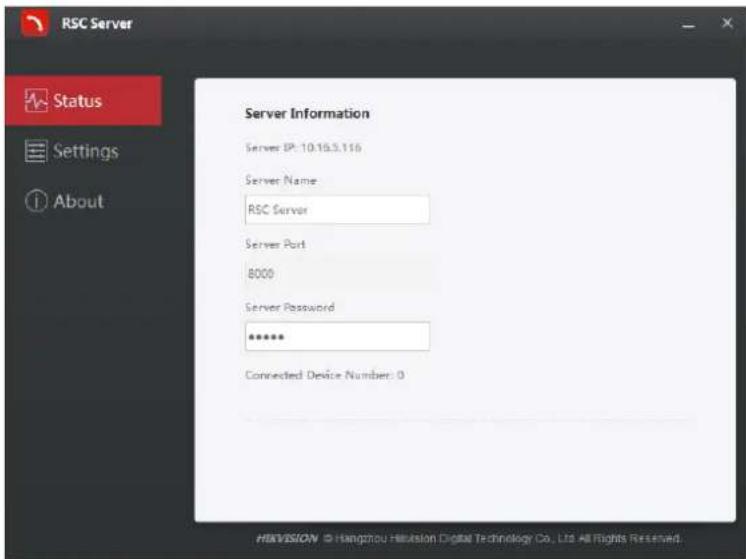
Figure 10-43 Run the RSC Server
Step 2 You can click Status to check the server informaon, including the IP address, name, port, password of the server, and the connected device number.
Step 3 Click Seings to check the directory of saving the program les, enable or disable the feature of Auto-Run when OS starts, and select the language (Chinese/English).
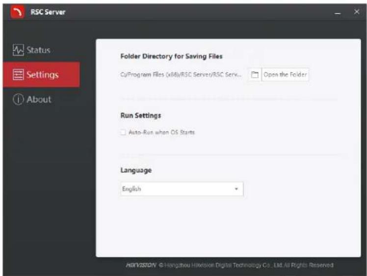
Figure 10-44 Local Conguraon of RSC Server
10.8.2 Controlling Remote Screen via RSC Server
Step 1 Enter the Video Wall interface and click + in the Camera list area, or click on + Add Device Device Management interface to add the RSC server.
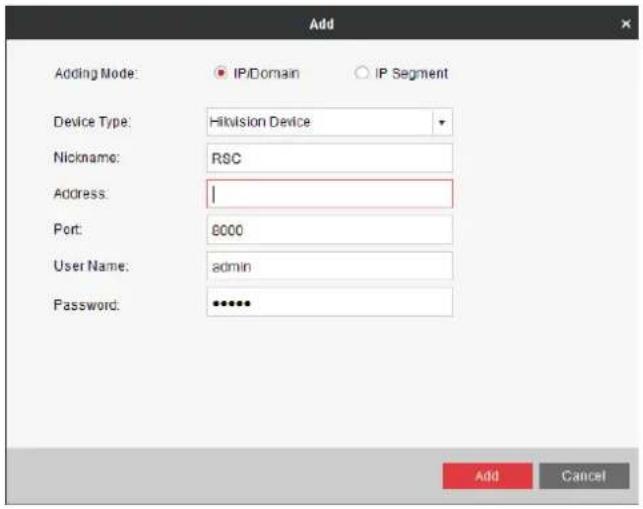
Figure 10-45 Add RSC Server
Step 2 Enter the parameters to add the RSC server. Please refer to Chapter 7.1 Adding an Encoding /Decoding Device to add the RSC server.

NOTE
The default user name is admin and the server password is 12345 and we highly recommend you to change the default password to avoid the security problem.
Step 3 The successfully added RSC server is listed in the camera list.
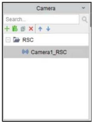
Figure 10-46 Added RSC Server
Step 4 On the camera list, drag the RSC server to the video output window.
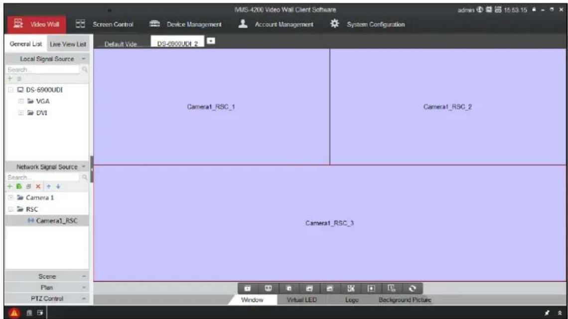
Figure 10-47 Link RSC to Video Wall
Step 5 Right-click on the window and select Screen Control to remotely control the signal source.

NOTE
The RSC server supports the screen control for 1-channel video output only.
Step 6 You can use the toolbar on the window's upper right corner to realize the operaons for image, video, PPT and remark.
natural_image
Close-up of a white hydrangea flower with green leaves, displayed within a photo editing window (no text or symbols on the flower itself)Figure 10-48 Screen Control Interface
- Click to display all the image les in the directory set in the RSC Sever.
natural_image
Blank white canvas with a small gray square in the top-left corner (no text or symbols)Figure 10-49 Screen Control Interface (1)
- Click to display all the video les in the directory set in the RSC Sever.
- Click to display all the PPT les in the directory set in the RSC Sever.
natural_image
A blank image with a small photo of orange tulips under a blue sky, no text or symbols visible.Figure 10-51 Screen Control Interface (3)
- Click ☑ to pop up the following remark tool bar. You can select a color and set the line width to make remarks on the PPT.

natural_image
Row of colored square icons on dark background, no text or symbols presentFigure 10-52 Remark Tool Bar
10.9 Remote Configuration
Purpose
On the Remote Conguraon interface, you can congregate the parameters of the added device, including the system, network, event, etc..
Step 1 On the Device Management interface, click to select an added device from the list and click Remote Conguraon to enter Remote Conguraon interface.
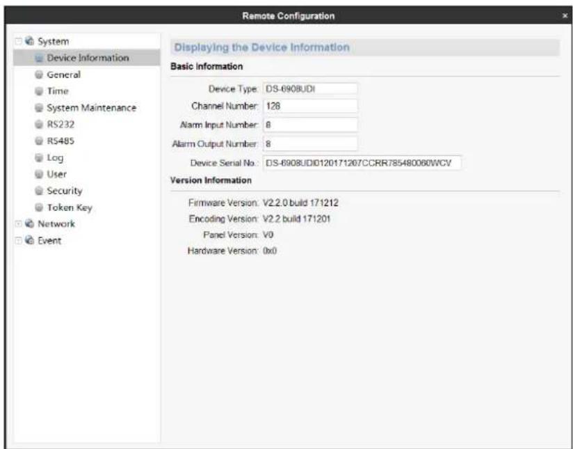
Figure 10-53 Remote Conguraon
Step 2 Congure the System parameters, Network parameters and Event parameters on the Remote Conguraon interface.
10.9.1 Configuring Ethernet Channel
Purpose
The Ethernet Channel is port link aggregaon technology or port-channel architecture used for the conncon between the switches.
Step 1 Click Remote Conguraon > Network > Ethernet Channel to enter the Ethernet Channel Sengs interface.
Step 2 Select a link number from the list.
Step 3 Check the checkbox to select the network interfaces to form a channel-group link, which can eecvely enhance the link transmission bandwidth.
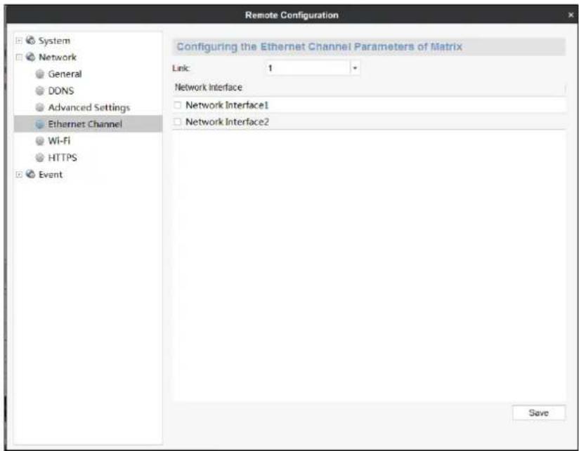
Figure 10-54 Ethernet Channel Sengs

NOTE
● The Ethernet Channel is not supported by DS-6901UDI.
● The switch connected to DS-6900UDI must be congured with the Ethernet Channel as well.
- Two adjacent network interfaces cannot be selected to form a link. For example, you can select Network Interface 1 and Network Interface 3, or Network Interface 2 and Network Interface 4.
- The network interface 1 corresponds to the GE1 interface, network interface 2 to G1, network interface 3 to GE2, and network interface 3 to G2 on the rear panel.
- The G1 and G2 can be used as 2G switch when the network interface 2 and network interface 4 are congured in Ethernet Channel.
10.10 Stream Media Server Configuration
Purpose
When the device network access channel number reaches the limit, or the network bandwidth is limited, you can realize real-me data transmission via stream media server to decrease the network pressure of the device.
10.10.1 Installing Stream Media Server
When you install iVMS-4200 video wall client soware, install stream media server in the same layer of directory of the video wall client soware.
10.10.2 Running Stream Media Server
Double click the desktop shortcut icon 📄, or enter the installaon directory (default: iVMS-4200 Video Wall\iVMS-4200 Stream Media Server), to open the stream media server. The main page is shown as below.
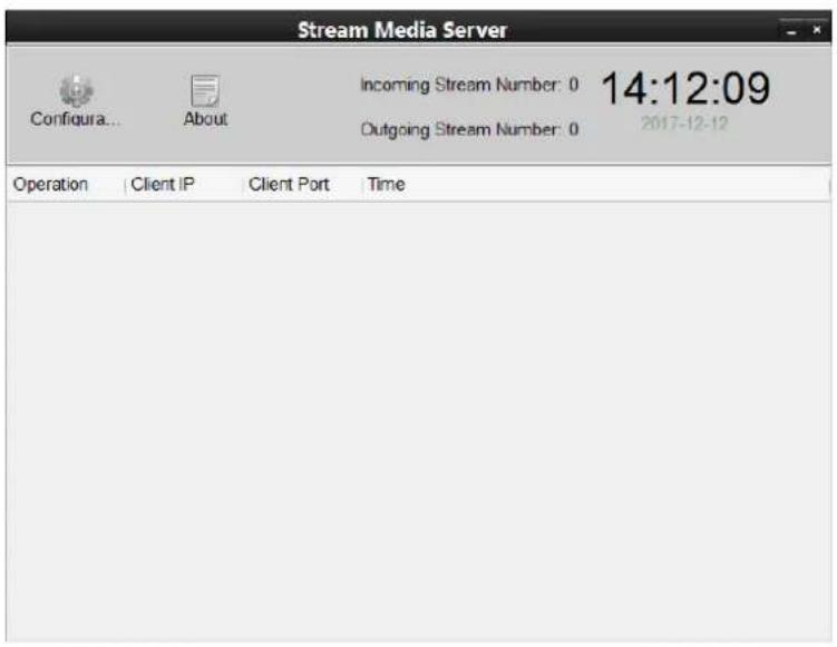
Figure 10-55 Stream Media Server
will appear in the taskbar in the lower right corner of the desktop, indicang the server is running normally.
10.10.3 Adding Stream Media Server
Step 1 Open iVMS-4200 video wall client soware.
Step 2 Click Device Management.
Step 3 Click Add SMS.
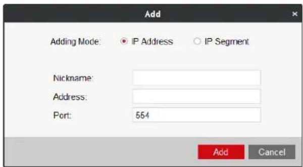
Figure 10-56 Add Stream Media Server
Step 4 Input Nickname, Address, and Port.
Step 5 Click Add to add the server.
10.10.4 Configuring Stream Media Server
- In Default Disabled Token Authencaon Mode

NOTE
Token authencaon is disabled by default. In the default disabled mode, follow the steps below to congure stream media server.
Step 1 Select the added stream media and click SMS Sengs on Device Management interface to set stream media server.
1) Check the groups or channels needing to get stream via stream media.
2) Click OK to save the setngs.
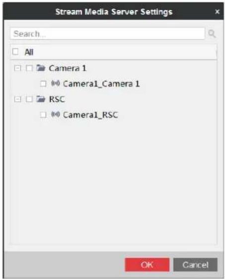
Figure 10-57 Stream Media Server Sengs
Result: The groups or channels geng stream via stream media will get stream again via stream media. Open the stream media server, and the channels geng stream via stream media will be displayed.
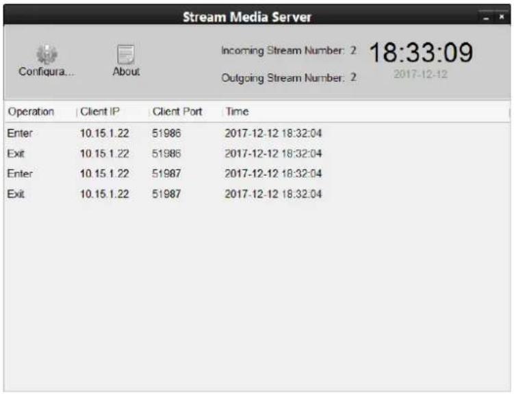
Figure 10-58 Stream Media Status
● In Enabled Token Authencaon Mode

NOTE
You can enable token authencaon by eding Setup le of iVMS-4200 Video Wall Client and Plugin file of iVMS-4200 Video Wall Stream Media Server. In the enabled mode, follow the steps below to enable token authencaon and congure stream media server.
Before you start
Step 2 Aer the installaon of iVMS-4200 video wall client, go to the installaon directory of iVMS-4200 video wall client (default: C:\Program Files\iVMS-4200 Video Wall\iVMS-4200 Video Wall Client).
Step 3 Select Setup.xml.
Step 4 Right click the le and click Edit.
Step 5 Change

Figure 10-59 Edit Setup File
Step 6 Save the sengs.
Step 7 Aer the installaon of stream media server, go to the installaon directory of stream media server (default: C:\Program Files\iVMS-4200 Video Wall\iVMS-4200 Video Wall Stream Media Server).
Step 8 Select Plugin.xml.
Step 9 Right click the le and click Edit.
Step 10 Edit

Figure 10-60 Edit Plugin File
Step 11 Save the sengs.
Steps
Step 1 Click System Conguraon of iVMS-4200 video wall client soware.
Step 2 Click Export to export Stream Media Safety Authencaon Conguraon to the local PC.
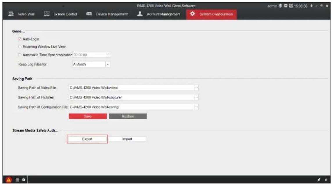
Figure 10-61 Export Stream Media Safety Authencaon Conguraon
Step 3 Import the stream media safety authencaon conguraon to the stream media server.
1) Run the stream media server.
2) Click Conguraon.
3) Click Import to import the stream media safety authencaon conguraon to the server.
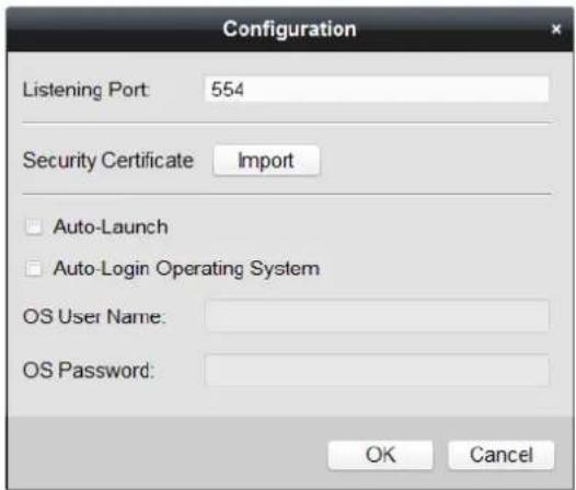
Figure 10-62 Import Stream Media Safety Authencaon Conguraon
4) Reboot the server to take the sengs into eect.
Step 4 Import the stream media safety authencaon conguraon to the decoder via iVMS-4200 video wall client soware.
1) Add the decoder to the iVMS-4200 video wall client soware. Refer to Chapter 10.2 Adding an Encoding/Decoding Device for details.
2) Click Remote Conguraon.
3) Go to System > Token Key.
4) Check Enable Token Authencaon.
5) Click Import Token Authencaon Informaon to import the XML le exported to the local PC before. Aer import, the key content will generate in Key text led.
6) Select Not Fill for Encrypon Algorithm Filling Format.
7) Click Save to save the sengs.

NOTE
For the other parameters of token conguraon, remain the default sengs.
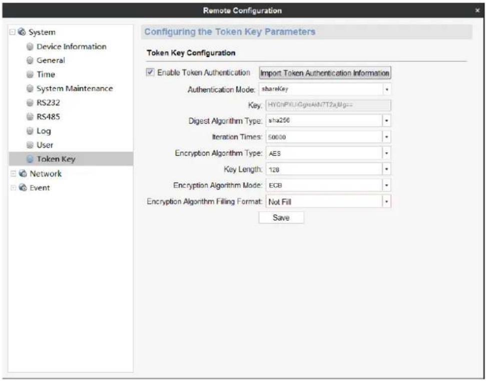
Figure 10-63 Token Conguraon
Step 5 Select the added stream media and click SMS Sengs on Device Management interface to set stream media server.
3) Check the groups or channels needing to get stream via stream media.
4) Click OK to save the setngs.
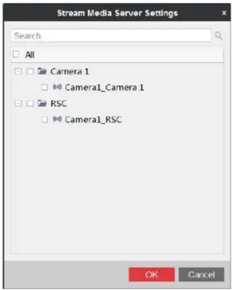
Figure 10-64 Stream Media Server Sengs
Result: The groups or channels geng stream via stream media will get stream again via stream media. Open the stream media server, and the channels geng stream via stream media will be displayed.

Figure 10-65 Stream Media Status
Chapter 11 Appendix
11.1 Specifications
Table 11-1 DS-6901/6904/6908 UDI Specicaon
| Model | DS-6901UDI | DS-6904UDI | DS-6908UDI | |
| Video/Audio output | VGA and DVI-I input | / | WSXGA: 1680×1050@60HzWXGA: 1440×900@60HzWXGA:1280×800@60Hz,1366×768@60Hz,1080p: 1920 × 1080@50/60HzUXGA: 1600 × 1200@60HzXVGA: 1280 × 960@60Hz720p: 1280 × 720@50Hz/60HzSXGA: 1280 × 1024@60HzXGA: 1024 × 768@60Hz | |
| Video/Audio output | HDMI output | 1-ch | 4-ch | 8-ch |
| 4K: 3840 × 2160@30Hz ( for even interface only)1080p: 1920 × 1080@50/60HzWSXGA: 1680×1050@60HzUXGA: 1600 × 1200@60Hz (for even interface only)720p: 1280 × 720@50Hz/60HzSXGA: 1280 × 1024@60HzXGA: 1024 × 768@60Hz | ||||
| VGA output | 1-ch | / | / | |
| 1080p: 1920 × 1080@50/60HzWSXGA: 1680×1050@60HzSXGA: 1280 × 1024@60Hz720p: 1280 × 720@50Hz/60HzXGA: 1024 × 768@60Hz | ||||
| BNC output | 1-ch | 2-ch, 1 DB 15 | 4-ch, 1 DB 15 | |
| Audio/Video decoding | Decoding resoluon | Up to 12MP | ||
| Decoding channel | 16-ch | 32-ch | 64-ch | |
| Decoding capability | 12MP@20fps: 2-ch8MP@30fps: 4-ch5MP@30fps: 6-ch3MP@30fps: 10-ch1080p@30fps: 16-ch | 12MP@20fps:4-ch8MP@30fps: 8-ch5MP@30fps: 12-ch3MP@30fps: 20-ch1080p@30fps: 32-ch | 12MP@20fps:8-ch8MP@30fps: 16-ch5MP@30fps: 24-ch3MP@30fps: 40-ch1080p@30fps: 64-ch | |
| Split screen | 1/4/6/8/9/12/16 | 1/4/6/8/9/12/16/25 | 1/4/6/8/9/12/16/25/36 | |
| External interface | Network interface | 1; 10/100/1000 Mbps self-adapve Ethernet interface | 2; 10/100/1000 Mbps self-adapve management network interface2; 10/100/1000 Mbps self-adapve Ethernet interface16; 10M/100Mbps self-adapve Ethernet interfaceWi-Fi interface | |
| Serial interface | 1 RS-232 (RJ 45), 1 RS-485 | |||
| Two-way audio in | 1-ch, 3.5 mm connector (2.0 Vp-p, 1 kΩ) | |||
| Two-way audio out | 1-ch, 3.5 mm connector (2.0 Vp-p, 1 kΩ) | |||
| Audio output | 1-ch | 4-ch, 1 DB 15 | 8-ch, 1 DB 15 | |
| Alarm in | 8-ch | |||
| Alarm out | 8-ch | |||
| General | Power supply | 12 VDC | 100 to 240 VAC | |
| Power consumpon | ≤ 15 W | ≤ 70 W | ||
| Working temperature | -10°C to 55°C (14°F to 131°F) | |||
| Working humidity | 10% to 90% | |||
| Dimensions (W × D × H) | 220 × 148 × 45 mm (8.66" × 5.83" × 1.77") | 440 × 311 × 44.5 mm (17.32" × 12.24" × 1.75") | ||
| Weight | ≤ 1.2 kg (2.65 lb) | ≤ 5.2 kg (11.4 lb) | ||
Table 11-2 DS-6910/6912/6916 UDI Specicaon
| Model | DS-6910UDI | DS-6912UDI | DS-6916UDI | |
| Video/Audio output | VGA and DVI-I input | WSXGA: 1680×1050@60HzWXGA: 1440×900@60HzWXGA: 1280×800@60Hz, 1366×768@60Hz,1080p: 1920 × 1080@50/60HzUXGA: 1600 × 1200@60HzXVGA: 1280 × 960@60Hz720p: 1280 × 720@50Hz/60HzSXGA: 1280 × 1024@60HzXGA: 1024 × 768@60Hz | ||
| Video/Audio output | HDMI output | 10-ch | 12-ch | 16-ch |
| 4K: 3840 × 2160@30Hz (for even interface only)1080p: 1920 × 1080@50/60HzWSXGA: 1680×1050@60HzUXGA: 1600 × 1200@60Hz (for even interface only)720p: 1280 × 720@50Hz/60HzSXGA: 1280 × 1024@60HzXGA: 1024 × 768@60Hz | ||||
| BNC output | 5-ch, 2 DB 15 | 6-ch, 2 DB 15 | 8-ch, 2 DB 15 | |
| Audio/Video decoding | Decoding resoluon | Up to 12MP | ||
| Decoding channel | 80-ch | 96-ch | 128-ch | |
| Decoding capability | 12MP@20fps: 10-ch8MP@30fps: 20-ch5MP@30fps: 30-ch3MP@30fps: 50-ch1080p@30fps: 80-ch | 12MP@20fps: 12-ch8MP@30fps: 24-ch5MP@30fps: 36-ch3MP@30fps: 60-ch1080p@30fps: 96-ch | 12MP@20fps:16-ch8MP@30fps: 32-ch5MP@30fps: 48-ch3MP@30fps: 80-ch1080p@30fps/3Mbps: 128-ch | |
| Split screen | 1/4/6/8/9/12/16/25/36 | |||
| External interface | Network interface | 2; 10/100/1000 Mbps self-adapve management network interface2; 10/100/1000 Mbps self-adapve Ethernet interface16; 10M/100 Mbps self-adapve Ethernet interface | ||
| Serial interface | 1 RS-232 (RJ 45), 1 RS-485 | |||
| Two-way audio in | 1-ch, 3.5 mm connector (2.0 Vp-p, 1 k Ω) | |||
| Two-way audio out | 1-ch, 3.5 mm connector (2.0 Vp-p, 1 k Ω) | |||
| Audio output | 10-ch, 2 DB 15 | 12-ch, 2DB 15 | 16-ch, 2 DB 15 | |
| Alarm input | 8 | |||
| Alarm out | 8 | |||
| General | Power supply | 100 to 240 VAC | ||
| Power consumpon | ≤ 108 W | |||
| Working temperature | -10°C to +55°C (+14°F to +131°F) | |||
| Working humidity | 10% to 90% | |||
| Dimensions (W × D × H) | 440 × 311 × 80 mm (17.32" × 12.24" × 3.15") | |||
| Weight | ≤ 6.4 kg (14.11 lb) | |||
11.2 FAQ
● Why cannot ping the decoder?
- Check the cable and the switch.
- Please refer to Chapter 4 to congregate the IP address of the decoder.
● Why cannot connect the decoder with client soware?
- Check the decoder IP address.
- Cable is connected.
- User name and password of decoder are correct.
- Why cannot play back the record les in DVR with decoder?
- Check the DVR network conneccon.
- Check the parameters of the playback le.
- Check if there are les existed in the selected me duraon.
● Why cannot decode the stream transported by stream media server?
- Check the network conncon between decoder and stream media server.
- Check if the stream media server port is connected with the port added on decoder.
11.3 List of Third-Party IP Cameras Access
| IP Camera Manufacturer | Model | Supported Video Format |
| Panasonic | SP306H | H.265+, H.265, H.264, H.264+, MJPEG, MPEG4, |
| SP336H | ||
| Sony | SNC-CH220 | |
| SNC-RH124 | ||
| Axis | P5532 | |
| Q7404 | ||
| Sanyo | VCC-HD2500P | |
| SAMSUNG | SND-5080P | |
| Bosch | NBC265P | |
| Zavio | D5110 | |
| Arecont | AC1305M | |
| Pelco | IX30DN-ACFZHB3 | |
| Onvif | Supported |

See Far, Go Further

- User Manual
- ALL RIGHTS RESERVED.
- About this Manual
- Trademarks Acknowledgement
- Legal Disclaimer
- Regulatory informaon
- FCC informaon
- FCC conditions
- EU Conformity Statement
- Industry Canada ICES-003 Compliance
- Applicable Model
- Safety Instructions
- Preventive and Cautionary Tips
- Table of Contents
- Chapter 1 Introduction ...... 1
- Chapter 2 Panels and Connections....3
- Chapter 3 Device Activation....8
- Chapter 4 Network Configuration ....13
- Chapter 5 Decoding Parameters Configuration....19
- Chapter 6 Decoding Operation....23
- Decoding Video on Video Wall 32
- Chapter 7 User Management ...... 44
- Chapter 8 System Configuration ...... 46
- Chapter 9 System Maintenance....50
- Chapter 10 Decoder Configuration and Operation by Client Software .... 52
- Operang Decoding 63
- Chapter 1 Introduction
- Description
- Features
- Powerful Decoding Capability
- Multiple Decoding Control Modes
- Integrated Capability
- Maintenance Management
- Chapter 2 Panels and Connections
- Front Panel
- NOTE
- Rear Panel
- Chapter 3 Device Activation
- Purpose
- Activating via SADP Software
- WARNING
- Activating via Web Browser
- Activating via Client Software
- Chapter 4 Network Configuration
- Configuring Basic Network Settings
- Configuring DDNS Settings
- - IPServer
- - PeanutHull
- NO-IP
- Configuring Security Control
- Chapter 5 Decoding Parameters Configuration
- Configuring Stream Settings
- Configuring Transparent Channel
- Configuring Synchronous Output Settings
- Configuring Personalized Settings
- Chapter 6 Decoding Operation
- Configuring Encoding Devices
- Adding an Encoding Device
- Modifying an Encoding Device
- Deleting an Encoding Device
- Configuring Video Wall
- Configuring Decoding Output
- Configuring BNC Output
- Configuring HDMI Output
- Decoding Video on Video Wall
- Interface Description
- Dragging Channels to the Video Wall
- Openning Window via Coordinate
- Managing Decoding
- - Stop Decoding
- - Decoding Status
- - Turn on Audio
- - Decoding Delay
- ● Enable Smart Informaon
- - Stream Informaon
- Switching Encoding Channel
- Configuring Auto-Switch of Cameras
- Roaming Window
- Zooming in/out Roaming Windows
- ● For one roaming window:
- ● For divided roaming sub-window:
- Configuring Scene
- Chapter 7 User Management
- Chapter 8 System Configuration
- Checking Device Information
- Configuring Time Settings
- ● Conguring Time Synchronizaon by NTP Server
- ● Conguring Time Synchronizaon Manually
- Configuring RS-232 Serial Port
- Configure RS-485 Serial Port
- Chapter 9 System Maintenance
- Importing Configuration Files
- Exporting Configuration Files
- Upgrading the Device
- Restoring the Default Settings
- Rebooting the Device
- Chapter 10 Decoder Configuration and Operation by Client Software
- Interface Description
- Adding an Encoding/Decoding Device
- Configuring Video Wall
- Adding a Video Wall
- Modifying a Video Wall
- Deleting a Video Wall
- Configuring Virtual Screen
- Purpose:
- Configuring Decoding Parameters
- Configuring Decoding Output
- Configuring BNC Output
- Configuring HDMI Output
- LCD
- LED
- Operating Decoding
- Dragging Channels to the Video Wall
- Opening Window for Non-LED Screen
- Opening Window for LED Screen
- Managing Decoding
- Configuring Auto-Switch Decoding
- PTZ Control
- Playback
- Configuring Scene
- Configuring Window
- ● Conguring Window Division Mode
- - Zooming in/out Roaming Windows
- • Conguring Window Parameters
- Decoding Thermal Network Camera
- Configuring the Thermal Network Camera Parameters
- Configuring Temperature Measurement
- Configuring Dynamic Fire Source Detection
- Configuring Ship Detection
- Configuring VCA
- Decoding Thermal Network Camera on the Video Wall
- Controlling Remote Screen
- Configuring the RSC Server
- Controlling Remote Screen via RSC Server
- Remote Configuration
- Configuring Ethernet Channel
- Stream Media Server Configuration
- Installing Stream Media Server
- Running Stream Media Server
- Adding Stream Media Server
- Configuring Stream Media Server
- - In Default Disabled Token Authencaon Mode
- ● In Enabled Token Authencaon Mode
- Before you start
- Steps
- Chapter 11 Appendix
- Specifications
- FAQ
Brand : Hikvision
Model : DS-6900UDI Series
Category : Digital decoder