
Shogun Studio - Dictaphone Atomos - Free user manual and instructions
Find the device manual for free Shogun Studio Atomos in PDF.


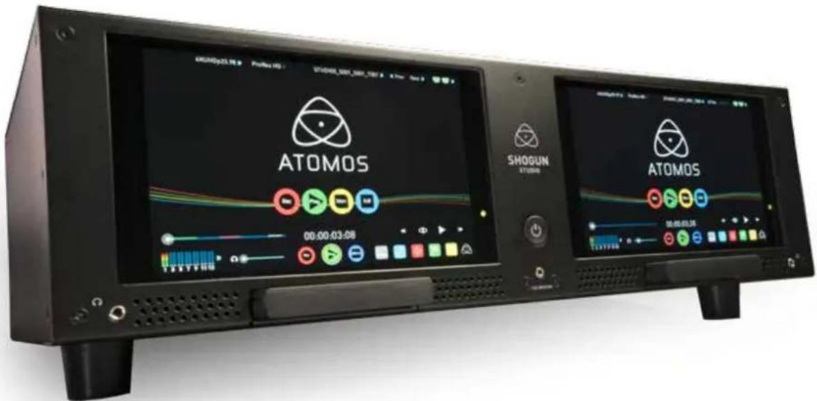
| Product Type | 4K/HD Dual-Channel Monitor-Recorder |
| Dimensions (without rack ears) | 447 x 152 x 251 mm (17.6 x 6.0 x 9.9 in) |
| Dimensions (with rack ears) | 490 x 152 x 251 mm (19.3 x 6.0 x 9.9 in) |
| Rack Height | 3RU |
| Weight | 5.0 kg / 11 lb |
| Construction | Steel construction for durability |
| Operating Power | 20 – 60W |
| Redundant Power Supply | Yes, dual AC inputs |
| Display | 7.1" SuperAtom IPS, 1920x1200, 325 PPI, 16:9 native |
| Video Inputs (per channel) | 1x HDMI 1.4b, 1x 4K-SDI 12G/6G/3G/1.5G |
| Video Outputs (per channel) | 1x HDMI 1.4b, 1x 4K-SDI 12G/6G/3G/1.5G |
| Supported Recording Codecs | Apple ProRes (HQ, 422, LT), Avid DNxHD (220x, 220, 145, 36), DNxHR (HQX, HQ, SQ, LB) |
| Audio Inputs (per channel) | 2x XLR (Line/Mic/Pro, 48V phantom), embedded 12ch SDI, 8ch HDMI |
| Audio Outputs (per channel) | 2x XLR, 1x 3.5mm headphone jack |
| Timecode | Embedded HDMI/SDI, LTC input, Genlock input, Record Run, Time of Day, Auto Restart |
| Remote Control | RS422, Ethernet (AMP), HDMI/SDI triggers, touchscreen |
| Storage Media | 2x Master Caddy II slots (2.5" SATA HDD/SSD), exFAT format |
| Accessories Included | 5x Master Caddy II, 2x rack ears, 4x rubber feet, 2x large feet, 2x IEC power cables, screen cleaning cloth, QuickStart guide |
| Warranty | 1 year standard, upgradeable to 3 years upon online registration |
| Care and Maintenance | Keep away from liquids, magnetic fields; use anti-static precautions for drives; clean screen with included cloth; avoid sharp objects on screen |
Frequently Asked Questions - Shogun Studio Atomos
User questions about Shogun Studio Atomos
0 question about this device. Answer the ones you know or ask your own.
Ask a new question about this device
Download the instructions for your Dictaphone in PDF format for free! Find your manual Shogun Studio - Atomos and take your electronic device back in hand. On this page are published all the documents necessary for the use of your device. Shogun Studio by Atomos.
USER MANUAL Shogun Studio Atomos
EDITION 1: NOVEMBER 2015
Have you registered your Shogun Studio yet?
Upgrade to 3 year warranty now
Register now to receive communication on all future updates
Web: www.atomos.com Sales: sales@atomos.com Support: support@atomos.com
Warranty & Conditions 3
Introduction
- What's included 5
2. What you also need 6
Spinning Disk Drives (HDD) 6
Solid State Drives (SSDs) 6
Mechanical Shock and Vibration 6
Backing up and archiving 7
4K SDI Cables 7
3. Mounting disks in the Master Caddy II 8
4. Attaching Rack Ears and Feet 9
5. Connecting and powering up 10
Power ON/Power OFF 10
6. Shogun Studio connections
7. Master Caddy II and Screw Mounts
Master Caddy II / Screw Mounts / Modularity 13
8. Using the Shogun Studio
Using the Shogun Studio 14
Category 1: Operating Settings 14
Category 2: Shot Setup & Monitor Tools 14
Category 3: Main Controls, REC, PLAY & MENU 14
Home Screen / Menu functions 15
File Naming / Date & Time / Display Options 16
Screen lock / Shogun Studio Info 17
Input Menu 18
Storage Capacity Indicator / Formatting HDD/SSD / Unit Name 19
Audio panel 20
9. Monitoring and Recording
Before recording / Choosing your recording format 21
SmartControl / 6 ways to start recording 22
Waveform Monitoring 23
Luma Overlay / RGB Parade / Vectorscope 24
Monitor Assist 25
Focus Assist / Zebra / False Color 26
Blue Only / Grid Lines / Focus Assist Settings 27
SmartLog
Exporting .xml 29
Display option menu
Anti-shock technology 31
File Recovery 31
10. Timecode
11. HD Pulldown
12. Record mode options
13. Playback & Playout
14. Connecting and Editing 40
Connect to Input 40
NLE Support 40
exFAT compatibility 40
Transferring files 40
Importing / Import into Final Cut Pro 41
SmartLog with FCPX 42
15. Software Upgrades
Updating AtomOS (Firmware) 43
- Technical Specifications 44
4
The Shogun Studio is designed to a high standard but there are some things you should be aware of to prolong the life of the unit and for your own safety.
Using the Shogun Studio safely
Although the Shogun Studio is very lightweight compared to all the devices it replaces, it is still a solid object that could cause injury if misused.
- Always make sure that the Shogun Studio is mounted securely and is unable to fall onto anyone nearby. This is especially important when there are children present who might be tempted to pull on cables.
- Always ensure that cable runs to the Shogun Studio are clearly visible and do not present a trip hazard.
- Do not place on uneven or unstable surfaces.
- Do not insert anything but Shogun Studio Master Disk caddies in the Master Disk slot on the front of the Shogun Studio.
- Do not touch the Shogun Studio's screen with sharp, metallic or abrasive objects.
- Do not expose to strong electrical or magnetic fields.
- Do not expose to or use near liquids, rain or moisture.
- Do not dispose of the Shogun Studio in municipal waste and do not incinerate it, always follow local regulations for safe disposal.
Care of disk drives
Spinning disks and SSDs are very sensitive to damage from static electricity. Please observe all the usual ESD precautions when handling them.
Please see the section Mechanical shock and vibration later in this manual for information about how to handle and care for your disk drives.
SDI Cables
Please remember that SDI cables use locking connectors and will not simply pull out if they are jerked or tripped over. They are therefore a significant trip hazard to your equipment, which may be damaged if the cables are misused.
HDMI cables
Please remember that HDMI cables do not use locking connectors and will simply pull out if they are jerked or tripped over. Please ensure your cables make a secure connection and avoid flexing them excessively to maintain reliability.
User Manual Conventions
To keep things simple but clear, we've only adopted two conventions in this manual:

A helpful tip, suggestion or something to note because it's not obvious at first.

An important note or warning
Notice
Copyright © 2015 ATOMOS Global Pty Ltd ('referred to as ATOMOS'). All rights reserved. All information in this document is subject to change without notice. No part of the document may be reproduced or transmitted in any form, or by any means, electronic or mechanical, including photocopying or recording, without the express written permission of ATOMOS. A reference to ATOMOS includes its related entities, subsidiaries and parent company.
Trademarks
Shogun Studio and ATOMOS are registered trademarks of ATOMOS. Apple, the Apple logo, AppleShare, AppleTalk, FireWire, iPod, iPod Touch, Mac, and Macintosh are registered trademarks of Apple Inc. Final Cut Pro, QuickTime and the QuickTime Logo are trademarks of Apple Inc. DNxHD, DNxHR and Avid logo are registered trademarks of Avid Technology, Inc. All other trademarks are the property of their respective holders.
International Hardware Limited Warranty
ATOMOS warrants that:
- Main product, not including TFT/LCD, or any external accessories, will be free from defects in materials and workmanship for a period of 1 years from the date of purchase, the user may upgrade to a 3 year warranty upon registering their product at www.atomos.com
- The TFT/LCD, HDD/SSD Docking Station, Master Caddy II and Cable will be free from defects in materials and workmanship for a period of 1 year from the date of purchase.
This warranty is exclusively for the benefit of the original purchaser and is not assignable or transferable.
If during the warranty period the product is shown to be defective ATOMOS may at its option:
a) replace the goods or supply equivalent ones,
b) repair the goods,
c) pay the cost of replacing the goods or of acquiring equivalent ones and
d) paying the cost of having the goods repaired;
The customer must notify ATOMOS of any defect in the goods in writing prior to the expiry of the warranty periods set out above. The customer will be solely responsible for returning the goods to ATOMOS or its authorized distributor. Upon acceptance of a warranty claim by ATOMOS, where ATOMOS repairs or replaces the goods, it will be responsible for reasonable shipping costs incurred in sending the goods to the Customer, provided that customer is located in a country in which ATOMOS has an authorized distributor or repair centre or agent.
Warranty Exclusions
This warranty applies only to defects in workmanship and does not cover defects caused by:
- Neglect;
- Improper or negligent acts or omissions;
• Repairs or attempted repairs; - Tampering with or modification of the goods;
- Connection to incompatible equipment or power sources;
- Exposure to water or weather;
- Exposure to magnetic fields or corrosive liquids or substances;
- Physical damage
Except as stated in this warranty, Atomos, it's vendors, agents, resellers and distributors disclaim in their entirety all other warranties, express or implied, including without limitation all warranties of merchantability or fitness for a particular purpose. The remedies outlined in this warranty are the exclusive remedy a customer from defective goods, which are subject to the warranty.
Atomos does not warrant that the goods will operate in a manner that is error free, or uninterrupted. The goods are not intended to be the primary or only data storage device for data – customers are solely responsible for back up and protection of data.
Software License Agreement
IMPORTANT, PLEASE READ CAREFULLY. THIS IS A LICENSE AGREEMENT.
This ATOMOS software, related documentation, any included sample images files (the "Software"), is protected by copyright laws and international copyright treaties, as well as other intellectual property laws and treaties. The Software is licensed, not sold.
This End User License Agreement ("EULA") is a legal agreement between you (either an individual or a single entity) and ATOMOS with regard to the copyrighted Software provided with this EULA. Use of the Software provided to you by ATOMOS in whatever form or media, will constitute your acceptance of these terms, unless separate terms are provided by the software supplier, in which case certain additional or different terms may apply. If you do not agree with the terms of this EULA, do not download, install copy or use the Software. By installing, copying or otherwise using the Software, you agree to be bound to the terms of this EULA. If you do not agree to the terms of this EULA, ATOMOS is unwilling to license the Software to you.
-
Eligible licensees. This Software is available for license solely to purchasers of the ATOMOS Shogun Studio, who have purchased a unit manufactured by ATOMOS Shogun Studio and purchased through an ATOMOS authorized reseller, with no right of duplication or further distribution, licensing or sub-licensing.
-
License Grant. ATOMOS grants you a personal, non-transferable and non-exclusive right to use the copy of the Software provided with this EULA. You agree you will not copy the Software except as necessary to use it with the ATOMOS Shogun Studio. You agree that you may not copy the written materials accompanying the Software. Modifying, reverse engineering, translating, renting, copying, transferring or assigning all or part of the Software or any rights granted hereunder, to any other persons or reverse engineering the hardware on which the Software runs, is strictly prohibited. The software is license, not sold. You acknowledge that no title to intellectual property in the Software is transferable to you. You further acknowledge that title and full ownership rights to the Software will remain the exclusive property of ATOMOS and/or its suppliers, and you will not acquire any rights to the Software, except as expressly set forth above. All copies of the software will contain the same proprietary notices as contained in or on the Software. All title and copyrights in and to the Software (including but not limited to any images, animations, video, audio, text incorporated), the accompanying printed materials, and any copies of the Software are owned by ATOMOS or its suppliers.
-
Reverse engineering. You agree that you will not attempt, and if you are a corporation, you will use your best efforts to prevent your employees and contractors from attempting to reverse compile, derive circuits, modify, translate or disassemble the Software and/or the Atomos Shogun Studio in whole or in part. Any failure to comply with the above or any other terms and conditions contained herein will result in the automatic termination of this license and the reversion of the rights granted hereunder by ATOMOS.
ATOMOS reserves the right to terminate this license without prejudice to any additional recourse ATOMOS may have against you if you violate any of its terms and conditions.
Registration + Warranty Upgrade
Standard warranty is 1 year. Register to upgrade your warranty to 3 years. Visit: www.atomos.com/registration
Introduction
Building on the architecture of the Shogun platform, the Shogun Studio leverages the features and functions found on cameras to build them into your rack. Harnessing the latest 4K/HD recorder, monitor and playback technologies the Shogun Studio offers a feature set that will help facilities existing HD workflows and provide the option for creating 4k Masters.
Following the same core Atomos principles of Record, Playback, Monitor and Edit the Shogun Studio allows you to over come many of the challenges faced with in live events, outside broadcast environments, production galleries, post production facility MCR, ProAV / Signage, on set DIT, sports officiating and many more.
Atomos defined the ability to migrate away from MPEG based GOP codecs with high levels of compression and reduced color accuracy by capturing content direct from the sensors of any camera that outputs a clean feed such as studio cameras and outputs from vision mixers and even RAW out puts from large sensor Cinematic cameras in to visually lossless edit ready Apple ProRes and Avid DNx edit ready codecs.
Software updates and information is available at:
www.atomos.com/support
AtomOS
HDMI
HD-SDI
ProRes
natural_image
Digital display screens showing city night scene with network interface and navigation icons (no readable text or symbols)The Shogun Studio comes with a standard 1 year warranty on all parts and accessories. You can upgrade to a 3 year warranty on the main Shogun Studio unit alone (excluding IPS screens) by registering your Shogun Studio online at www.atomos.com/registration
This will enable us to let you know about updates to the product and other important information surrounding your purchase.
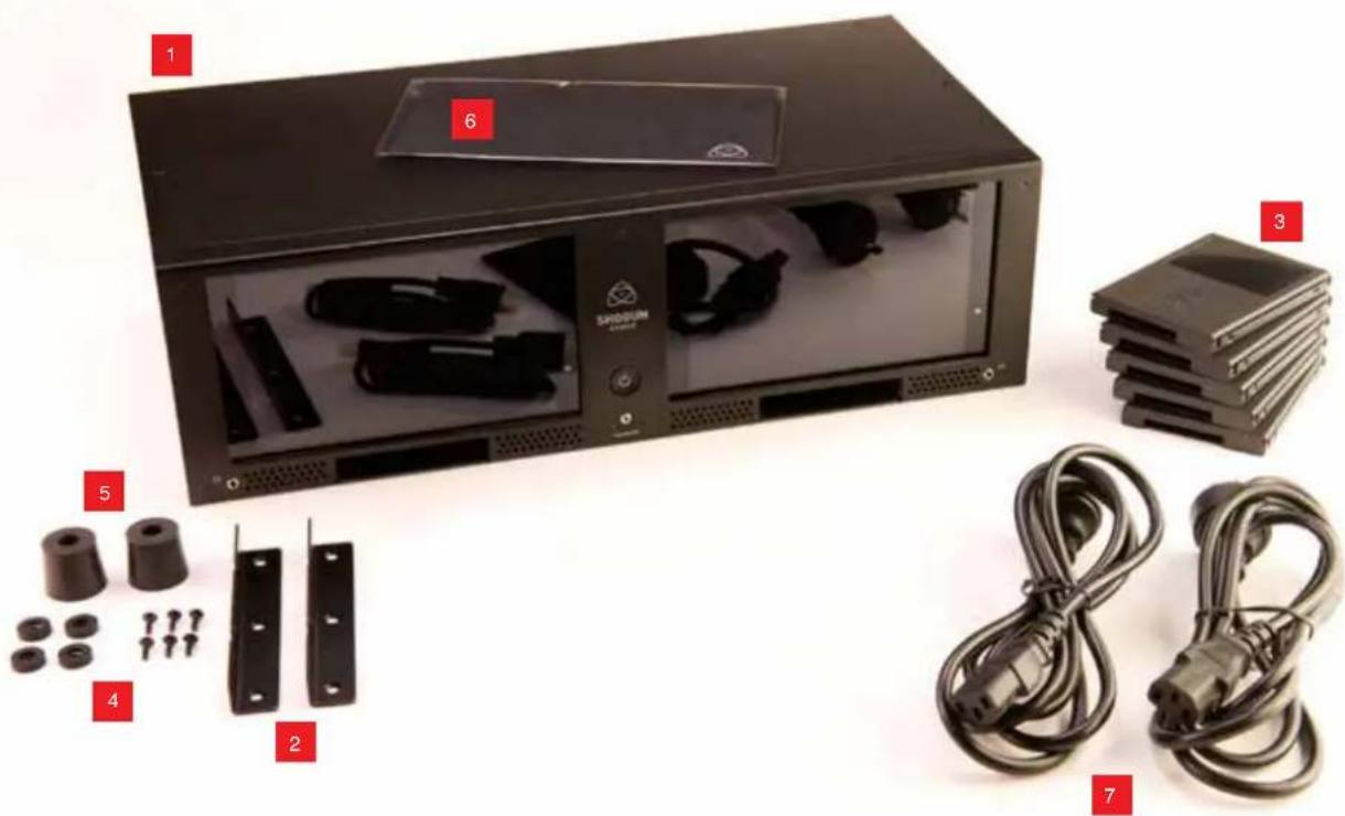
Shogun Studio is supplied with the equipment listed below. Additional Master Caddy II, Spyder Calibrator and HDMI cables are available from your local Atomos Reseller.
Box Contents:
- 1x Shogun Studio Unit
- 2x Rack ears with screws
- 5x Master Caddy II
- 4x Rubber feet with screws
- 2x large rubber feet (for elevating the front of the unit)
- 1x Screen cleaning cloth
- 2x IEC power cable (or external PSU for Japan)
- 1x QuickStartGuide
* Contents may differ slightly from those shown here.

Atomos does not include storage and your package will not contain any spinning disks or SSDs. You can buy these locally to keep running costs as low as possible.
For recommend drives, refer to the Technical Specifications of this manual. For the most up-to-date information please visit:
http://www.atomos.com/drives
natural_image
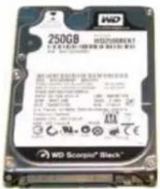
Exterior view of a black SODIUM device with labeled components including connectors, cables, and storage racks (no text or symbols on main body)Widely available 2.5" drives are the basic storage medium for 4k Monitor recorder. We work closely with all the leading drive manufacturers to qualify as many options as possible. Hard drives / HDD or Spinning disk can only be used for HD recording. Solid State Drives / SSD are required for 4K recording or for more demanding production environments that may not be suited to HDDs.
See the section below about when you should consider using SSDs.


Which drives should you use?
There are so many drives available, and newer models appear all the time. We are not able to test all drives but here are some guidelines.
Spinning Disk Drives (HDD) are recommended for recording up to 1080p30/1080i60 HD video only
Solid State Drives (SSDs) are recommended for recording up to 4kUHDp30 and 4kDCIp30 from RAW
Speed and reliability are the main factors. Here are a few things to bear in mind:
- Disk drive data rates tend to be given in megabytes per second, and codec data rates are normally given in megabits per second. It's very easy to get confused. But there's no need to be, because all you have to do to convert megabits to megabytes is divide by 8. So if you're recording at 220 megabits per second, that's going to result in 220/8 megabytes per second, which is 27.5 megabytes per second.
- We recommend at least 7200 RPM drives. Just remember that the higher the bit-rate of the codec you're using, the faster the drive needs to be, with 4K recording your data rate is four times from that of HD recording, please ensure your drive is capable of keeping up with 4K write speed requirements.
Atomos regularly test hard drives – please check this link before purchasing drives: http://www.atomos.com/drives
Mechanical Shock and Vibration for Spinning Disk HDD's
Hard disks are precision mechanical devices that need to be handled carefully. The use of mechanical drives or Solid State drives will vary depending on the intended filming application.
We can't give rigid guidelines because there are so many different kinds of drives, each which has different mechanical properties. You may find variations between drives of the same type.
What we have found is that mechanical drives are suitable for most purposes that don't involve harsh vibration or mechanical shocks. We would not advise using mechanical disks if there is a likelihood that they might be dropped onto a hard surface.
Here are some things that you should bear in mind when using spinning disks:
- Even though spinning drives can withstand substantial shocks when they are not in use, they are more vulnerable when running. Harsh treatment that may not actually damage the drive may interrupt recordings at a much lower level of severity. We recommend that you experiment with your drives by testing them in the conditions that you normally work in.
- Do not bang or jolt the Shogun Studio while recording.
- Do not use spinning drives (HDD) for recording 4k video
- You will find noticeable differences in the ability of drives to withstand shock and to continue recording during vibration and movement.
File Recovery
- Your Shogun Studio is able to detect when the drive is under stress and it will recover from any break in a recording by waiting until the drive is ready to continue, and then resuming from that point. If frames have been dropped because of shock or vibration, a "Skippy" Kangaroo symbol will appear on the home screen on the Shogun Studio, in the top left hand corner of the display. This means that you will not normally have to restart the Shogun Studio, even if a recording has been interrupted by mechanical disruption to the disk drive. (see Monitoring and Recording : Anti-shock technology for more information)
Taking into account most usage scenarios, we think that mechanical disks will be suitable in the majority of cases when recording up to 1080p30 HD. Spinning disks are most sensitive when they are rotating. It is obviously best to avoid dropping them but many disks now have a "drop detector" that will lock the most fragile mechanical parts in place and protect them from surprisingly hard knocks. We recommend that if you want to experiment with this, you do so with a drive that doesn't contain the day's shoot!
Backing up and archiving
Remember that no storage medium, including tape, optical disks, spinning disks and flash memory, is completely immune from failure.
You should bear this in mind when deciding how to manage your recorded content. At the very least, you should consider the consequences for you and your business if your storage medium were to suffer from a sudden failure, and you should back up your content accordingly. Hard drives that you can use for archiving are becoming increasingly affordable. You may find that it is completely feasible for your to keep your master Shogun Studio disks on a shelf (just like tapes!), and, as a backup, store copies on large hard drives, RAID arrays, Network Attached Storage (NAS) or LTO.
4K SDI cables (not included)
SDI cables are robust physically and electrically: you should rarely have problems with signal transmission unless your cables are either damaged or too long. Please remember that SDI cables use locking connectors and will not simply pull out if they are jerked or tripped over. They are therefore a significant trip hazard, and also a hazard to your equipment, which may be damaged if the cables are mishandled or of a low grade. Please ensure you test and check your SDI cables for 4k, for longer runs cables of a Belden 1694A specification are recommended.
HDMI cables
HDMI cables are robust physically and electrically: you should rarely have problems with signal transmission unless your cables are either damaged or too long.
Not all HDMI cables are created equal and there are a variety of different qualities available. Please make sure you test your cables prior to shooting.
Also check your connectivity at both the camera connector and the recorder/monitor connector to make sure you have a firm connection to avoid any signal drop out.

If the SDI / HDMI cable is removed while recording the "Skippy" image will also be displayed. To remove touch Skippy and he will disappear ready for his next notification.

Refer to page 31: Atomos Anti-shock technolog for more information about "Skippy".
3. Mounting disks in the Master Caddy II
Mounting drives in the Master Caddy II
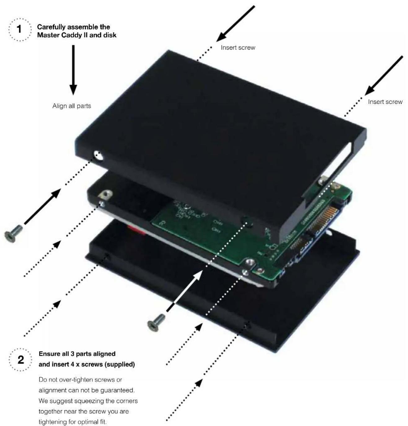
Insert the disk into the caddy, and secure with four screws. The caddy is light and the disk just needs to be held securely. Don't over-lighten the screws. There are no connections to make because sliding the caddy into the Shogun Studio or the Docking station makes all the connections for you.
The Master Caddy can't be inserted the wrong way round. Always make sure that the disk connector faces the slot in the Shogun Studio. You have to be quite firm to push the Master Caddy II into place, but don't push too hard, just in case something isn't set up or aligned properly.
There is very little that can cause problems and the most likely thing is that the Master Caddy isn't properly flush with the drive inside. A quick visual check will confirm this.
Spinning disks and SSDs are very sensitive to damage from static electricity. Please observe all the usual precautions when handling them, especially DO NOT EVER touch the exposed SATA connector as static electricity may be harmful to your disk.
Master Caddy II drives are backwards compatible with previous Atomos recorders, however Master Caddy 1 is not forward compatible with the Shogun Studio due to the compact latch design.
4. Attaching Rack Ears and Feet
Shogun Studio can be configured for both rack mount and desktop use. Included in the box are 4 x small feet, 2 x large feet and rack ears along with all the mounting screws for these accessories.
Rack ears
natural_image
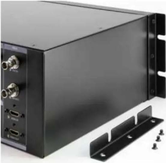
Black industrial electronic device with ports and mounting bracket (no visible text or symbols)Remove the metal rack ears and screws from the protective packaging. Line up the holes and screw in the supplied screws with the appropriate Philips head screwdriver. Take care to screw each screw in 3/4 of the way in and then gradually tighten all screws so you can ensure correct alignment.
Feet
natural_image
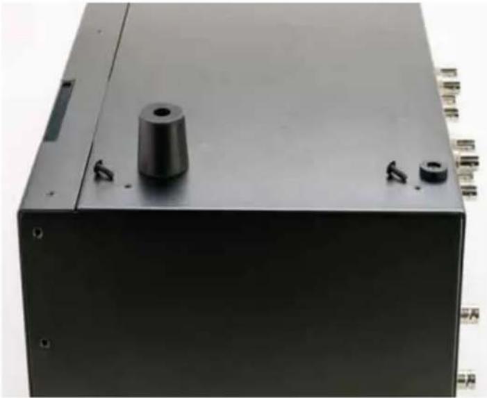
Black industrial machine casing with a cylindrical component and two small buttons, no visible text or symbols.Depending on the intended use of the Shogun Studio select the appropriate rubber feet. Whilst the power is disconnected turn the unit over and locate the four screw holes for the feet. The 4 small feet can be attached and used during rack mount operation. The 2 x larger feet are designed to raise the front of the unit to an angle to allow for easier desktop viewing. It is advised to remove these larger feet during rack mount operation.
5. Connecting the Shogun Studio and powering up
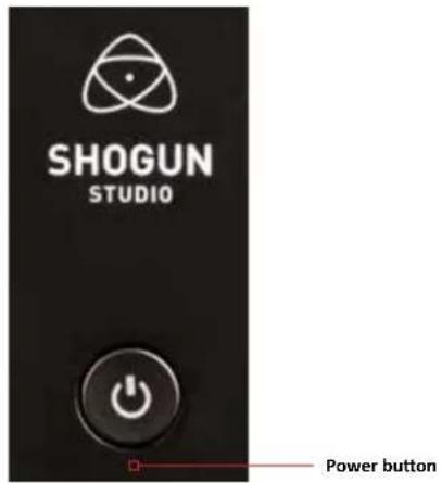

The Shogun Studio does not feature a software off function in the menu and can only be powered down from the physical switch on the front of the unit.
We recommend that you connect Shogun Studio directly to a stable mains connection or via a power distribution unit / strip to an interruptible power supply in your rack. The Shogun Studio has 2 x AC inputs and we advise using both where possible.
Connecting Power-up and about PSUs:
The rear bottom left hand side of the unit are located AC1 and AC2 inputs with IEC C14 sockets. Connect the provided power cables to the sockets and then connect to mains power. The dual power supplies internally balance the power draw across both units and additionally allows for backup power if one of the power supplies fail.
If a PSU fails or a single power supply is connected, a warning screen will be displayed. To continue using the unit, activate single power supply mode by clicking the blue X in the top corner of the message box. The power input icons in the top left corner of each unit will display a green and yellow icon.

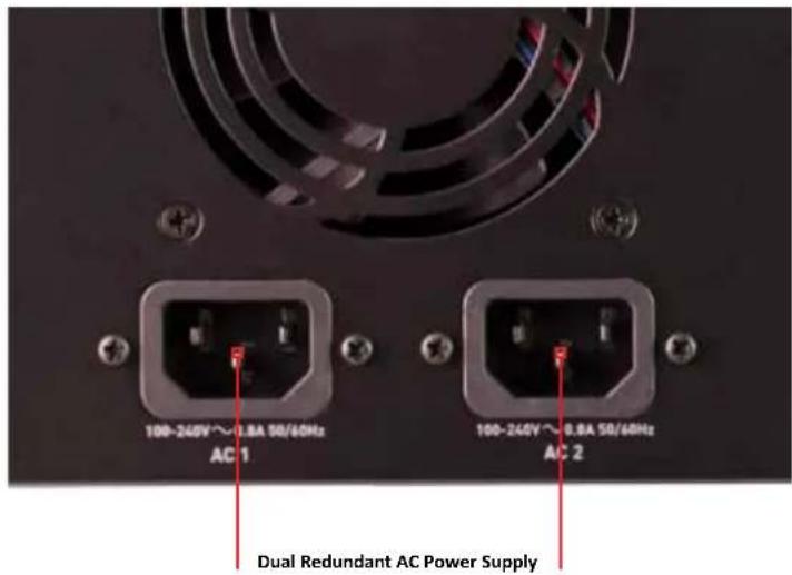
With both power supplies connected, press the Power button in for 3 seconds and both units will power up and the LED light on both channels will illuminate red.

On initial connection of power the controller will go through a boot phase and the fan will spin up. Once this has happened the power button can be used to turn on the device.
Once powered, pressing the power button for 3 seconds will turn both units off. After power down the unit's fan will remain on whilst the internal controller of the Shogun Studio shuts down.
6. Shogun Studio Connections
Looking at Shogun Studio from the front, recorder channel 1 is on your left side and recorder channel 2 is on your right side.
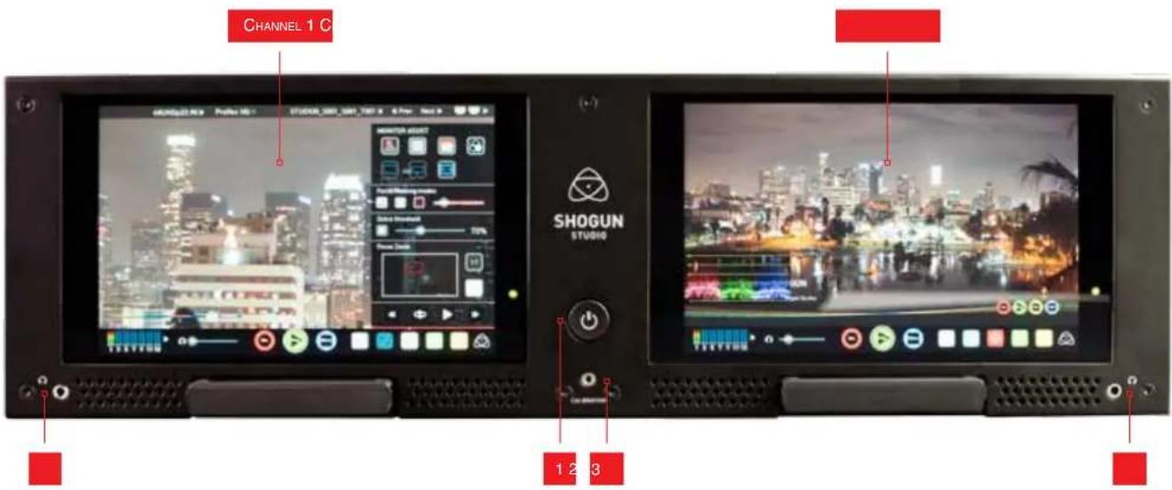
1. Power Button
The power button as described earlier controls the simultaneous turning on or off both recorder channels.
2. Calibration Port
The Calibration 2.5mm jack port beneath the power button allows for connection of the optional Atomos Spyder unit. This single port is able to be used to calibrate both devices and each channel will display as a separate option in the Atomos Calibration software, an updated release of this software will be available via http://www.Atomos.com/support
3. Headphone Ports
Both channels have an independent 3.5mm headphone jacks for monitoring audio. The volume control is operated via the touch screen interface.
The rear panel of Shogun Studio has been laid out symmetrically to align the connections with the recorder channel monitor when viewed from the front.
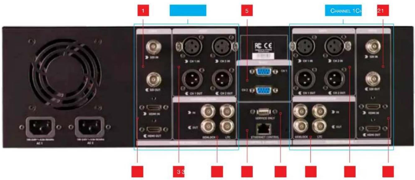
1. 4K/HD-SDI
4k/HD-SDI in: The SDI input connections are 12G compliant and backwards compatible meaning that it can be used for 12G, 6G, 3G and 1.5G signals. This input is also used to input RAW signals from supported cameras.
4k/HD-SDI out: This is for connection to an external monitor or other device with an SDI input. It carries a loop-through of the incoming SDI or HDMI signal in record and standby mode, and the playback signal when the Shogun Studio is in playback mode. This output can carry either a 4K or HD signal (with the option to down scale the 4K input to HD). The SDI <-> HDMI conversion is always live allowing for instant conversion with out any setup.
2. HDMI
HDMI IN: The video input is a full size HDMI 1.4b connection used to receive the video and when supported by your device embedded audio and Timecode. This is both displayed and recorded to the Atomos recorder/monitor storage media.
HDMI OUT: This is for connection to an external monitor or other device with an HDMI input. It carries a loop-through of the incoming HDMI or SDI signal in record and standby mode, and the playback signal when the Shogun Studio is in playback mode. This output is 1.4b and can carry either a 4K or HD signal (with the option to down convert the 4K input to HD). The SDI <-> HDMI conversion is always live allowing for instant conversion without any setup.
3. Analogue Audio
Each recorder channel has 2x XLR inputs and 2x XLR outputs. The inputs can be configured at Line, Mic and Pro level in the Audio menu. The inputs can also provide 48V Phantom power to compatible microphones. The XLR outputs are for monitoring and the audio channel routed to them can be selected via the headphones selection in the Audio menu.
4. Synchronization
Each Recorder channel has GenLock input and output via BNC as well as LTC Timecode input and loop output.

Please note that the output of the Genlock and LTC are only for loop out and the Shogun Studio cannot generate either GenLock or LTC Timecode.
LTC settings can be accessed in the Timecode menu.
5. RS422 9pin D-Sub
Each recorder has its own dedicated 9pin D-Sub for RS422 machine control. Simply connect your RS422 cable from your device or controller and Shogun Studio will receive and action the commands.
See page 38-39 for the supported RS422 commands.
6. Ethernet
The RJ45 Ethernet connection is for the remote control of the unit via AMP commands from devices that support this. See page 40-41 for supported Amp commands.
7. USB
The USB connection on the rear is for SERVICE ONLY and should only be used if instructed to do so as part of a firmware update.
6. Shogun Studio Connections
HDMI and SDI
Built in to the Shogun Studio are both SDI and HDMI inputs. This means that either input is able to be routed out of both the HDMI and SDI outputs at the same time. This allows you to use SDI cameras with other HDMI equipment or HDMI cameras in an SDI infrastructure. This is accessed via the input menu See page 18.
Video Scale Convert
Video out also has the option for a down scale to be applied allowing your 4k input to be converted to a 1080 HD output for use with existing HD equipment.
6. Inserting the drives
3D LUT Output
LUTs can also be selected to be applied to the outputs and routed out to other equipment via the HDMI or SDI connections.
Embedded Audio
The Shogun Studio can record 12 channels of digital audio embedded in the SDI signal, and 8 channels of digital audio embedded in the HDMI signal.
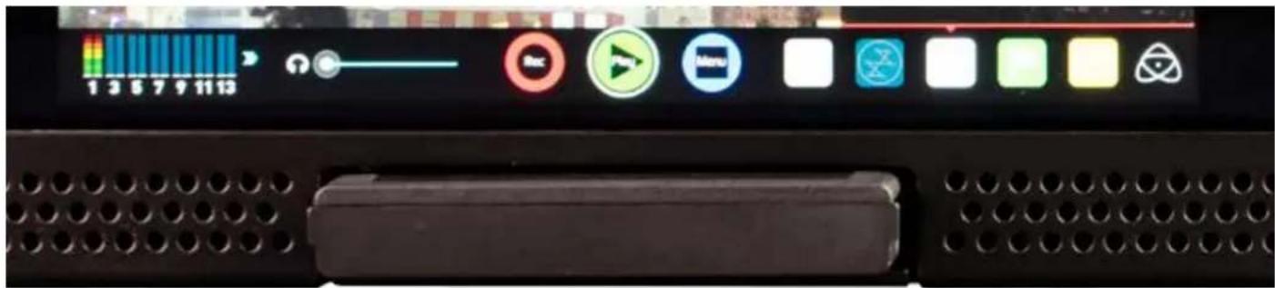
Master Caddy II Slot
On the front of the Shogun Studio a drive slot is located under the centre of each of the 7.1" SuperATOM IPS monitors.
To insert a drive make sure it is mounted correctly in the Master Caddy II and push the drive in to the slot. The side keys will guide the drive in to position and engage the drive with the SATA connector.

Do not attempt to insert a drive with out a Master Caddy II as this could damage the rear connector and the drive.
Master Caddy II - New 2 keyway system
The Master Caddy II is hot-swappable, so you can do this at any time – even while the unit is turned on. But don't do it while recording or you will get a corrupted file that may be unplayable. If files are incomplete your AtomOS will detect this and allow you to repair the file but in the case of power loss there will be frame loss of roughly 7 seconds.

The Shogun Studio does NOT have a release latch - it is friction-fit. Simply pull the Master Caddy II out using a finger and thumb on either side of the Master Caddy II and pull the drive out of the slot.
Master Caddy II is backwards compatible with previous Atomos recorders Master Caddy 1 is not compatible with Shogun Studio as the keyways are on one side only.
8. Using the Shogun Studio
The Shogun Studio is primarily controlled via an intuitive touchscreen interface that allows each unit to be controlled independently, for some record modes Channel 1 will become the Master and Channel 2 the Slave but each will maintain control of it's own WFM and monitoring tools.
Icons and buttons have been designed and laid out in a specific way to ensure operation is simple and fast.
The high definition 1920x1200 Home Screen displays all necessary technical and functional information.
The menu on the bottom of the screen is 120px allowing a full uncluttered 1920x1080 image to be visible on screen. Everything important for operation and adjustment is no more than one touch away. Here is how it works:
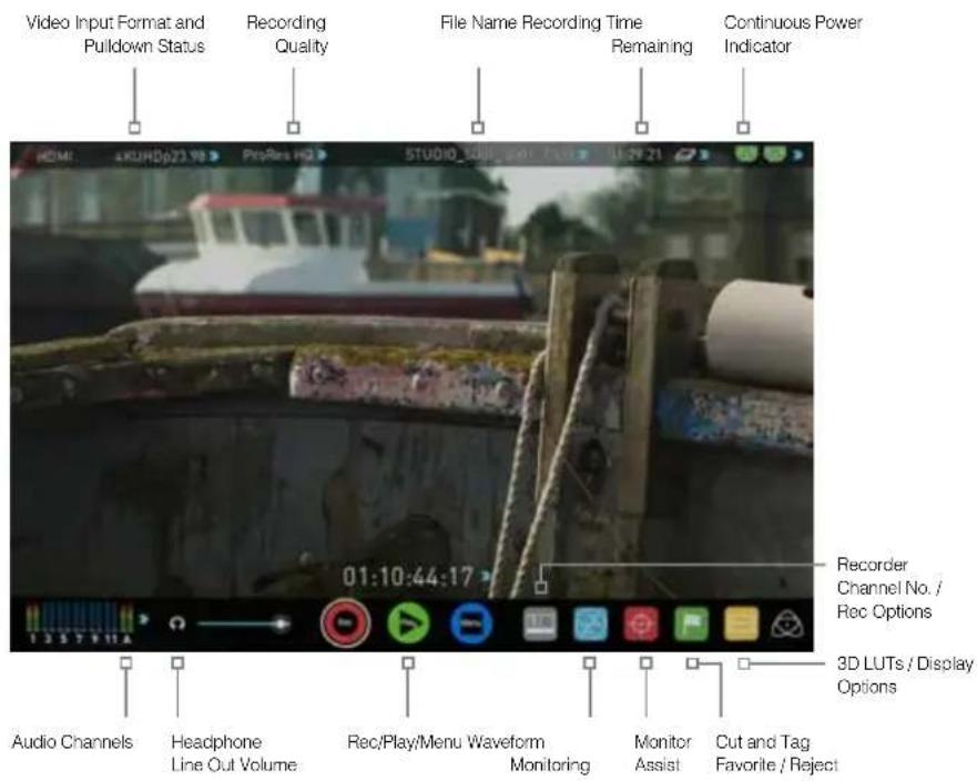

Touching the center of the screen at any time removes the top interface overlay, tapping again clears the bottom controls and a third tap brings all the options back up. Active Shot Setup or Monitor assist functions that are enabled will remain active when the menu system is cleared. This is to allow you to use the Shot Setup and Monitor assist functions at all times while shooting.
1 Category 1 – Operating Settings
This list of real-time operating settings can be adjusted or toggled when a BLUE ARROW is present. If the Blue arrow is disabled, the setting cannot be adjusted.
2 Category 2 - Shot Setup & Monitor Assist Tools
This list represents the icons and functions available for Shot Setup and Monitor Assist Tools:

Waveform Monitoring Functions
See page 23

Monitor Assist Functions
See page 25

Smart Log Cut and Tagging
See page 28

3D LUTs and Display Options
See page 29
Touch these icons to reveal more functional options in a sub-category. Touch the sub category icons to toggle the functions on or off. When a Shot Setup or Monitor Assist function is active, detailed settings for each Shot Setup tool are also available from this panel.
Touch the

icon to go back to the Home Screen at any time.
3 Category 3 – Main Controls REC, PLAY & MENU
The Main Controls of the unit are indicated by large round icons.
To enable recording
See page 15
For instant playback and review
See page 15
To make settings changes
See page 15
Home screen and menu functions
Rec (Record)
This is the icon you touch to begin a recording. Touch it again to stop a recording. While recording the Rec icon changes to a Stop icon and a red frame is present around the screen.
Standby

Recording

No input / No media

The Rec icon is dimmed and disabled if there is no valid video input OR, the disk is not formatted, or the disk is full. The button is dimmed because you cannot record.
Play
Touch this icon to play previously recorded clips. When you press the green Play button the Studio will switch to playback mode and automatically play the last recorded clip.
Standby
Navigation
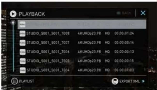
Shogun Studio uses a unit name, scene, shot and take convention to name the clips. Select the clip you want to play by touching the file name and this will start to playback.
No disk
The Play button will be dimmed and disabled if there is no disk or the disk is not formatted.
See page 19 - Formatting disks
Menu
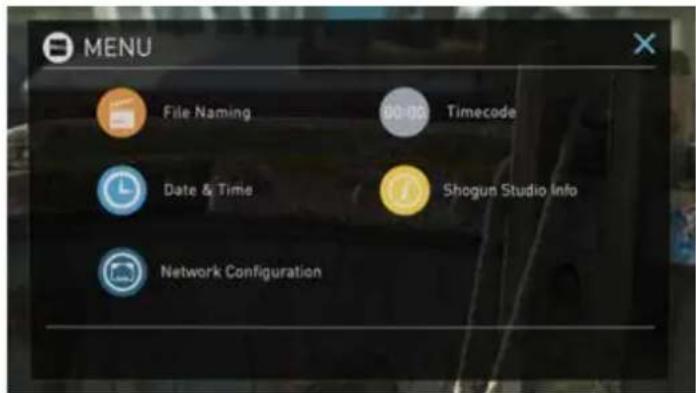
Pressing this takes you into a number of options which will explained next.

Time Lapse
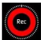
When the icon is shown with small interval lines around the red circle this means that Time lapse recording is activated.
For more information on Time lapse on page 35
Pre Roll
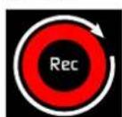
When a white circular arrow is show this means Pre Roll record is active.
For more information on Pre Roll see page 35

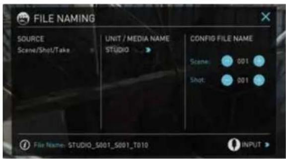
File Naming
Allows you to select the scene and shot number that will be recorded as well as change the unit / media name. To change the unit name tap the arrow under UNIT/MEDIA NAME, Use the left and right arrows to select a letter, and the up and down arrows to change its value.
To modify the scene and shot number under CONFIGURE FILE NAME, select plus or minus next to scene or shot (up to 999). The number you choose will then be shown in the file name at the top of the screen during recording, the take number is automatically increased with each take.

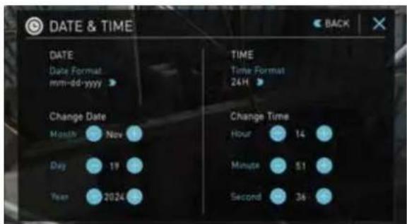
Date & Time
Allows you to adjust the date and time shown by the clock in the Shogun Studio. This will also change the time of day Timecode. Touching the Date & Time takes you into the Date and Time Screen.
Date formats (i.e. dd-mm-yyyy or mm-dd-yyyy) are selectable by tapping the blue arrow on "Select Date Format" Menu. Simply keep tapping until the desired format is shown. The Time, Month, Day and Year are selectable and can be modified by clicking the blue plus and minus icons next to the desired fields.

For both Time of Day Timecode and Scheduling start times for Time Lapse record mode it's important to ensure that the correct time is set.
8. Using the Shogun Studio cont.

Lock the Display Screen
You can lock the display of the Shogun Studio so that no changes can be made by mistakenly touching the screen, to lock the Shogun Studio simply short tap the power button. The screen lock function will simultaneously lock or unlock both Channels of the Shogun Studio.
Short tap the power button again to unlock the unit.

The lock screen can be combined with the display off function so that when lock is engaged the display is turned off. The Tally light on the front of the unit will still display Rec (Red) or idle (green) status. Locking of the display can be found in the Display menu.

UNLOCKED

LOCKED
Timecode
Takes you to the dedicated Timecode configuration page.

Refer to Page 32 of this manual for more information.

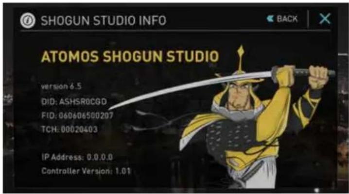
Shogun Studio Info
Shows the software (firmware) version and unique device ID (DID) of your Shogun Studio device. This will be required to activate the Avid DNxHD / Avid DNxHR codec. You can also check on the Atomos website to ensure you are running the latest firmware:
http://www.atomos.com/support

Remember that pressing on the Back button will always take you back to the previous menu.

Both Channels of the Shogun Studio are activated using a single code and this needs to be entered via Channel 1.
8. Using the Shogun Studio cont.
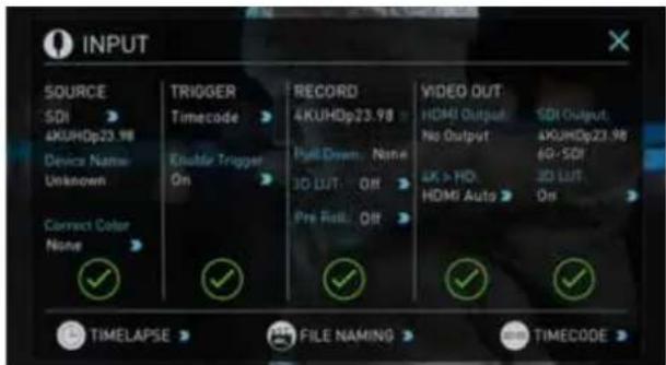
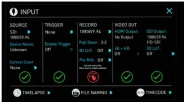
1. The Input Menu
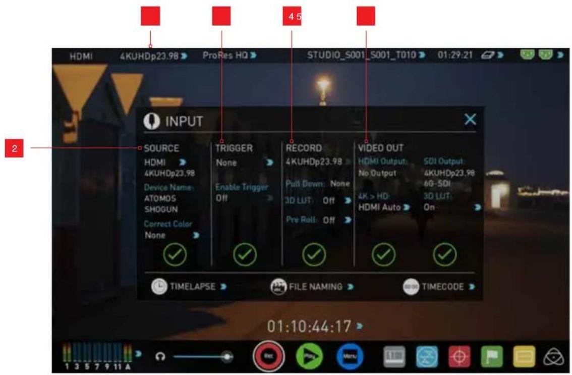
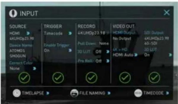
Simply tap the source input menu to the top left of the screen to bring up the input control panel. This panel will is a command centre for all devices connected to the Shogun Studio and will assist you with connectivity by indicating if the signal is active or if attention is required.
2. Source
Displays the input source currently connected to the Shogun Studio, simply tap ➤ to toggle between HDMI & SDI/SDI RAW inputs. You can have both HDMI and SDI inputs connected at the same time and use this menu to toggle between active inputs.
The current input resolution of the selected input source is displayed.
HDMI Devices will display an EDID Device name if the information is available from the HDMI device connected.
A green tick on Source indicates the Shogun Studio has locked signal on this input, a red cross indicates a signal or lock issue with the attached device, double check your cable and camera output settings. There is also an option to Correct Color input for use with Canon 5DMKIII that can be applied to the input.
3. Trigger
The Shogun Studio can be remotely triggered to record from your camera. Select the correct triggering option for your camera and set Enable Trigger to ON. Please refer to page 22 for more information.
4. Record
The record menu allows you to apply pulldown removal if recording from a source that applies pulldown to the output signal. Note for 3:2 Pulldown removal, movement in the frame may required to accurately lock signal, simply wave your hand in front of the camera to achieve lock. See page 34 for more details on pulldown removal.
The 3D LUT option allows you the option to burn in your selected LUT to the recorded file. Please be aware that this will permanently baked in and is non reversablereversible. When this option is selected a red LUT icon will flash in the top right hand corner of the display. See page 29 for more details on 3D LUTs.
Pre-roll allows for you to cache the last few seconds of footage so if you are late to hit record you won't miss the action. When this option is selected it will show a round arrow on the record button and flash a red Pre Roll icon in the top right hand corner of the display.

As Pre Roll is always cache recording once activated a number of features that are related to record settings will be locked. These include audio record channel select, 3D LUT record, Codec selection and Drive naming.
5. Video Out
This menu displays the active video format being output from both HDMI and SDI outputs. A 4k to HD down conversion can be applied to the output. This enables you to send a 4k input signal to a HD device. 3D LUTs can also be applied to the output independently of the Shogun Studio screen. This can be useful if you wish to monitor log footage on the Studio and show a graded image on an external display

Any selections in this option apply to both HDMI and SDI outputs.
Storage Capacity Indicator

Located in the top right of the screen. When a disk is inserted, the Storage Capacity Indicator will show the recording capacity of the drive This is calculated calculated based on codec settings and input signal type. If no input is connected it will show as --:--:-.
Formatting HDD/SSD

Touching the Storage Capacity Indicator on the home screen will take you to the Media Menu. This menu provides information on the drive currently inserted. To format the drive touch the Format Media button. A confirmation screen will give you the choice to continue or cancel the process.
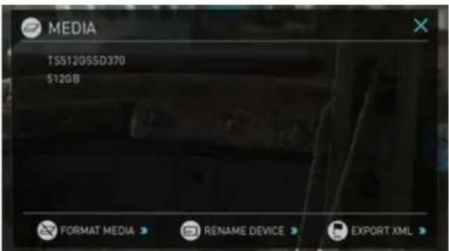
If you do not see your hard drive information, there may be a problem with the connection or drive. Try ejecting the drive and re-inserting the drive.
Please check the drive compatibility list prior to purchasing drives: http://www.atomos.com/drives

The Shogun Studio file system is exFAT. We recommend that you format each disk with the Shogun Studio and not your computer to ensure the correct parameters are set with the file system.
Unit Name

To access the unit name click the file name indicator from the home screen, then Unit Name.
The unit name serves two main purposes:
- Drive Naming: Naming the unit names the drive if the drive is formatted after the unit name has been set
- File Naming: File name is the current unit name as the start of the recorded clip name; STUDIO_S001_S002_T003
To access the unit name screen simply touch the blue arrow to the right of the unit name. Creating your own unit name by pressing the arrow to change and enter the letters in. Pressing OK will allocate the new unit name and return you to the menu screen.
Power Indicator
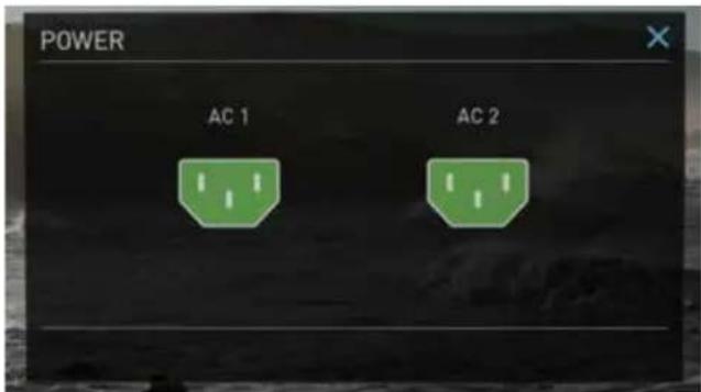
Pressing The power icons in the top right hand corner brings up the power menu which provides the status of the power connections
Monitoring & Recording Audio Channels
Located on the bottom left corner of the home screen you will see the Audio panel and quick headphone volume adjustment bar.
Tap the audio bars to bring up the audio panel.
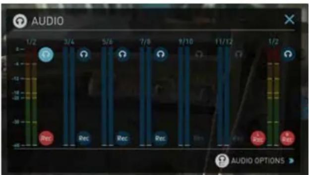
From this panel you can manage up to 12 digital channels (via SDI input) and 8 digital channels (via HDMI input) as well as 2 analogue audio channels (via the XLR Mic/Line in).
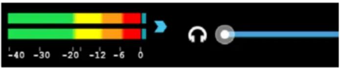

Recorded digital audio inputs work in correspondence to the video input source selected from the Input Menu, Analogue Line In is available to both selectable inputs. An active video input is required to record audio.
bar
| Quarter | Rec | AudiO | | :--- | :--- | :--- | | 1/2 | - | - | | 3/4 | - | - | | 5/6 | - | - | | 7/8 | - | - | | 9/10 | - | - | | 11/12 | - | - | | 1/2 | - | - |Each channel has a level meter assigned to Left & Right Channels; when there is active audio feed you will see the level indicator moving.
You can choose to record from any or all of the digital (SDI or HDMI) channels from the active source input as well as analogue inputs. Underneath each pair of audio channels you can see the Rec record button, when this is shown in red it is set to record, simply select the channels you want to record.
The Analogue audio input level is located to the far right, tap Rec to record this channel (XLR Line in Adapter Required)

Please note that if analogue audio is recorded it will be placed as the first pair of audio tracks in the recorded file.
Audio Options
To adjust the gain on the analogue input you need to bring up the audio options page by pressing in the lower right corner of the audio menu.
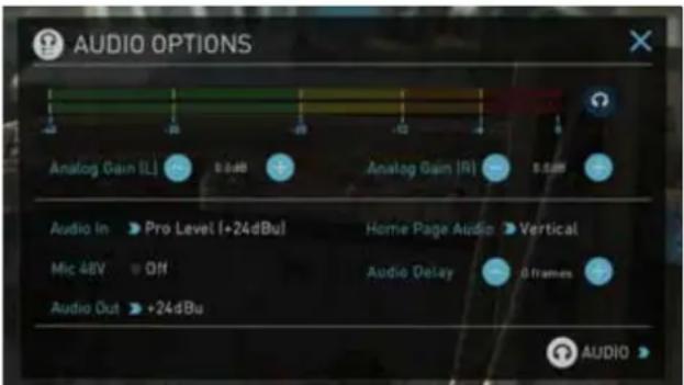
To select the input line Level to match your device. Options available are;
Line Level (-10 dBV)
Sets the analogue input channel to Line Level via the XLR to XLR connector.
Mic Level (-40 dBu)
Sets the analogue input channel to Mic Level via the XLR to XLR connector. With Mic Level selected you also have the option to provide 48V phantom power should your microphone require it. Please only use this when your microphone supports it and if unsure please consult the manual for the mic you are using.
Pro Level (+24 dBu)
Sets the analogue input channel to Pro Level Audio to via the XLR to XLR connector.
Analogue gain can then be tuned by incremental increase or decrease of up to +/- 20dB individually for both left and Right channels.

It is not possible to vary the gain if the signal input is from the SDI or HDMI connection because this is digital and is embedded in the signal. You can usually adjust this from the camera, please see your camera manual for operational details.
For the XLR outputs, the audio line out level can be adjusted by cycling through the Audio out options
To enable phantom power for mic's connected via the XLR connection, turn on the Mic 48V option.

Audio In must be selected as Mic Level.
For monitoring the audio, the Home Page Audio options Toggles the orientation of the audio bars displayed on the Shogun Studio home page in the lower left corner. Options available are;
Horizontal
Displays the 2 channels you are actively monitoring.
Vertical
Displays 12 channels + 2 Analogue Channels.
Monitoring Audio
To monitor the audio, tap the headphone icon 📋 next to the channel you wish to monitor from the headphone output.
Audio Delay
This option allows you to delay the Audio to be in sync with the video by adding in frame delays.
Audio During Playback Mode
When you enter into Playback mode on the Shogun Studio it will only output channels 1/2 on the headphones, please bear this in mind when you select the audio channels for recording.
9. Monitoring and Recording
Setting up for recording
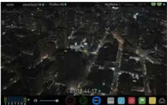
As soon as you connect a supported signal to the Shogun Studio input and have inserted a formatted drive the following will happen;
• The Rec icons will go solid
- The input source & format will be shown in the top left corner
• Audio inputs will show levels in bottom left corner
Ready to Record
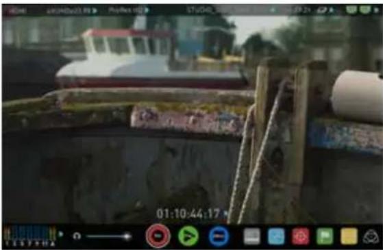
No Input / Disk Present
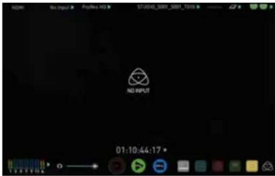
No Input / No Disk / No Disk Formatted
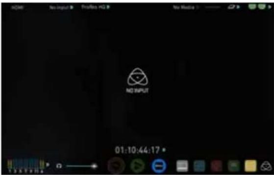
Input Present / No Disk
natural_image
Aerial night view of a dark urban area with illuminated streets and buildings, captured in a video editing interface (no readable text or symbols on the scene itself)Recording Checklist
- Check there is a valid signal by checking the input menu ensuring all fields display a green tick.
- Check the input signal is set to what you would like from the input menu: - Progressive
- Progressive with 2:2 or 3:2 pulldown (1080i inputs only)
- Interlaced (HD Only)
- If you see No Input for any reason please check your camera settings match a supported format for Shogun Studio. The formats supported are listed in the technical specifications page at the end of this manual.
- Connect any additional Analogue audio inputs and adjust gain accordingly.
- Check you have the correct audio channels in record, set to you required from the audio panel.
- Connect headphones and monitor the audio channels to make sure the sound is as expected
- Ensure the video is coming in as expected. Make sure the signal is clean and does not have any GUI overlays from the camera.
- Check you have the correct Scene & Shot number selected, this can be adjust by tapping the file name to the top of the screen.
- Check your drive is inserted and has been formatted by the Shogun Studio
- Check your Timecode and tigger settings are as required
- Choose how you will start/stop your recording
- Check for clean input:
By touching the screen in Monitor mode, you can remove the Atomos overlays to give you a clean screen. If any overlay graphics remain, these will be coming from your camera. Please check the settings on your camera to switch these off.
Choosing your recording format (Codec)
Select the codec name on to the top left of the screen to display the codec menu.
Avid DNxHD®
ProRes
From the codec section you can toggle between ProRes® or Avid DNxHD ^® *. The Quality menu allows you to toggle codec compression Apple ProRes offers 3 levels of compression (HQ, 422 & LT) DNx offers 4 (220x, 220, 145, 36 ) and DNxHR is available in HQX, HQ, SQ and LB. The expected record time available from each codec selection is automatically calculated from the available space on the media inserted.
If Avid DNxHD / DNxHR is required, you must activate it first. This can be done at www. atomos.com/support - DNxHD 220x/DNxHR HQX are 10bit, all others are 8 bit, DNxHD36 is a proxy codec.
More information regarding Apple ProRes data rates can be obtained online from Apple ProRes whitepaper PDF document.
9. Monitoring and Recording cont.
SmartControl
SmartControl is a versatile set of functions used to control the starting and stopping of recording by automatic or external means. This section outlines the different methods to start and stop recording.
Shogun Studio Start and Stop record control can be triggered by the following methods:
- Home Page Touch Screen
- HDMI/SDI Rolling Timecode trigger
- HDMI Camera trigger
- SDI Camera trigger
- RS422 Control
- Ethernet AMP control
1. Home page Touch Screen
By pressing Rec (Record) and STOP to end recording
2. SDI / HDMI Rolling Timecode Trigger record
If the camera is Record Run mode, recording can be stopped or started by a moving Timecode via HDMI or SDI.
When enabled the camera and the Shogun Studio will start and stop recording simultaneously.

Rolling Timecode trigger is for use in older cameras with TC only & no trigger. If your camera is set to FREE RUN this trigger will start recording immediately. Please be that aware not all cameras have Start/Stop flags for triggering record, especially older cameras. In such cases rolling trigger in REC RUN will need to be used to trigger recording automatically at the same time as the camera starts recording.
3. HDMI Camera trigger record
The HDMI Camera trigger is available for supported cameras, There is a flag within the digital signal that lets the Shogun Studio know the start/stop record has been pressed on the camera; in turn this will trigger the Shogun Studio to start/stop recording at the same time as the camera.
4. SDI Camera Trigger record
The SDI Camera trigger is manufacturer-specific, you will need to select the appropriate manufacturer for your camera from the input menu. There is a flag within the digital signal that lets the Shogun Studio know the start/stop record has been pressed on the camera; in turn this will trigger the Shogun Studio to start/stop recording at the same time as the camera.
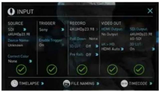
To enable this set TRIGGER to the camera manufacturer in the INPUT Menu.

When the manufacturer is selected in Camera trigger, this will disable the Timecode trigger.
Waveform Monitoring
AtomOS6 has a newly improved Waveform Monitoring control panel which can be enabled with only a few button presses.
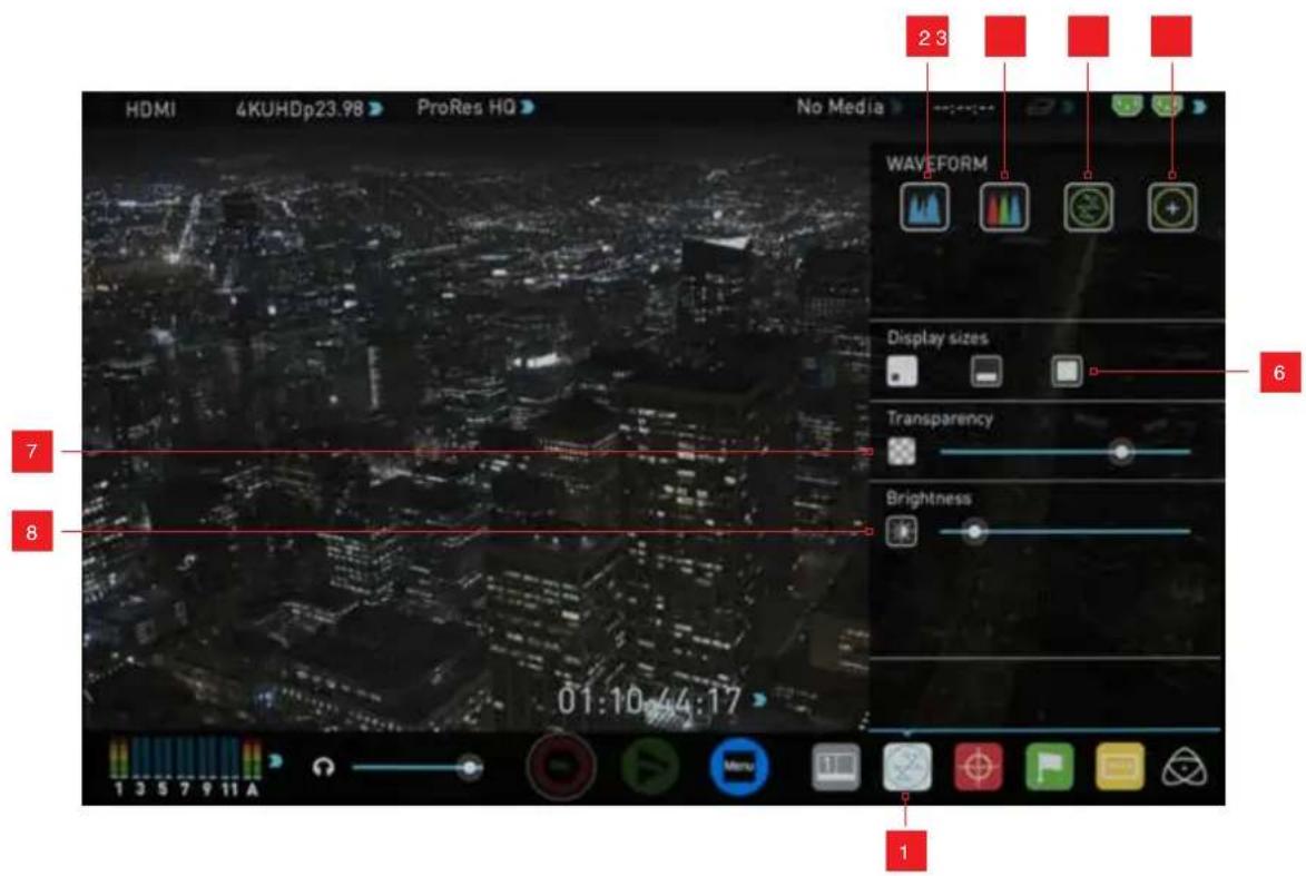
- Waveform Monitoring Menu
- Luma Parade
- RGB Parade
- Vectorscope
-
Vectorscope Zoom
-
Waveform Size (1/4, 1/3 and Full Screen view)
- Transparency
- Waveform Brightness
What is Waveform Monitoring?
Waveform Monitoring is used for measuring the brightness, luminance or chroma values from a video input signal. This feature has several benefits to the production workflow including:
- Ensuring camera to camera matching accuracy when shooting multicam.
- Returning to locations for additional pick-up shots.
• Assisting with colour correction.
• Camera white and black balance
How to use
To enable the Waveform Monitor, press the Waveform Monitoring icon on the home screen.
The Waveform Monitoring icon will only be visible if there is an input signal detected.
9. Monitoring and Recording cont.
Waveform Monitor Types
Inside the Waveform Monitoring menu, two types of Waveform Monitors are available for use:

Luma Parade Vectorsco


RGB Parade Vectorscop

Luma Parade, RGB Parade, Vectorscope and Vectorscope Zoom are enabled simply by touching the corresponding icon and will be by default displayed at the bottom right hand corner.
Luma Parade
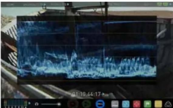
natural_image
Digital display showing a dark blue abstract waveform or signal with no readable text or symbolsThe Luma parade is a great way to visualize the dynamic range of your image, allowing you to protect exposure of both your high lights and shadow detail. It's particularly useful when shooting with a low contrast LOG curve so you can extract more detail out in post production.
RGB Parade
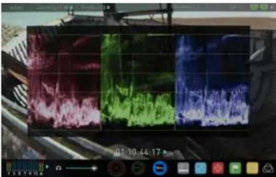
RGB Parade will monitor the level of Red, Green and Blue from an input source. The RGB channels are displayed side by side. This can be used to check to white balance. Just point the camera at something white and the Red, Green and Blue levels should match if white balance is setup correctly on the camera

The Waveform Monitor will remain on screen when hiding the overlays ensuring the focus remains on calibrating your image.
Vectorscope
natural_image
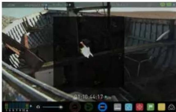
Exterior view of a modern building with a bird perched on a platform (no signage)The Vectorscope display shows colour information of hue (shown as a phase vector), and saturation (measured by outward distance from the centre). This is useful for checking if an image is under or over saturated and for calibrating multiple cameras to ensure greater consistency between shots.
Vectorscope Zoom
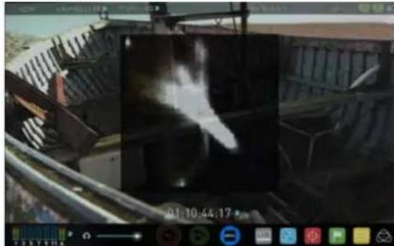
The Vectorscope Zoom shows a scaled up view (x8) of the centre of the vectorscope.
Waveform Monitor Settings
From within the Waveform Monitoring menu you can access the display settings for the waveform monitor.
To change the size of the waveform, press on the 1/4, 1/3 or Full Screen icons and the display will update immediately.

orm Si

ettings


To toggle between Waveform Monitor sizes of 1/4, 1/3 and Full Screen from the Home Screen, tap in the bottom left corner of the screen.

Brightness

transparency
The Brightness slider directly controls the intensity of the waveform while the Transparency slider adjusts the transparency values of the waveform display on screen.
9. Monitoring and Recording cont.
Monitor Assist
AtomOS features Smart Monitor tools that help with making your shot picture perfect. Easily access Focus Peaking, Zebra, False Colour and Blue Only Exposure to check image is in focus, noise free and correctly exposed. Options for safe area/ title area markers along with aspect ratio markers and anamorphic desqueeze functions are also available.
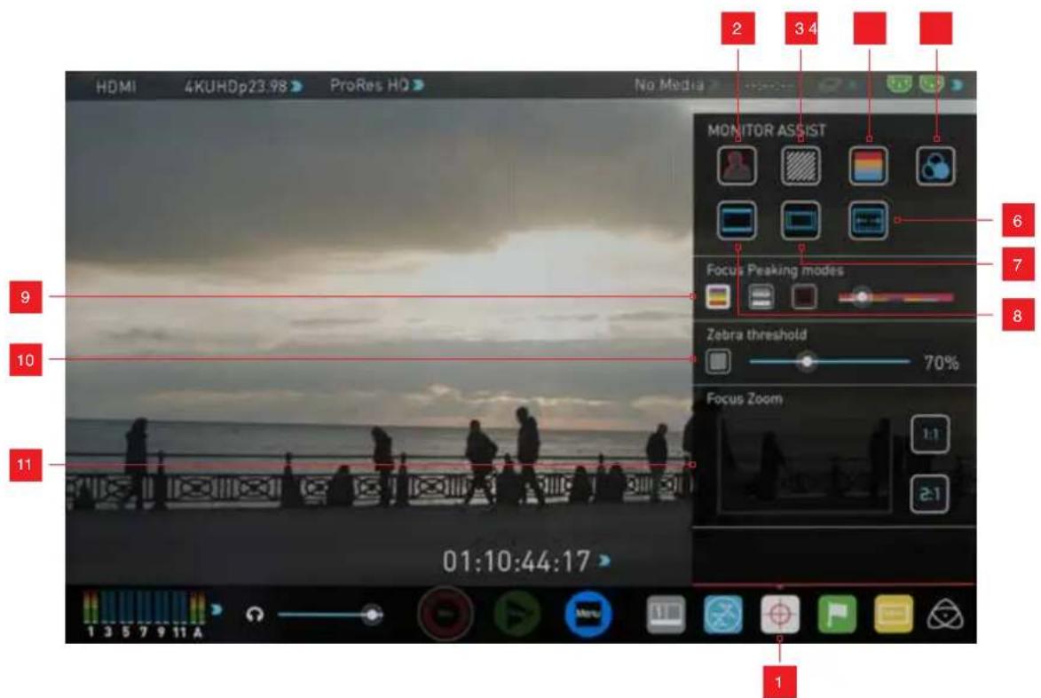
- Monitor Assist Menu
- Focus Peaking
- Zebra Pattern
- False Color
- Blue Only Exposure
-
Anamorphic De-squeeze
-
Safe Area / Title Lines
- Cinema / TV Guides
- Focus Peaking Display (Colour / Monochrome /
Edges Only)
- Zebra Threshold
- Focus Zoom with Pan & Scan
How to use
To enable the Monitor Assist functions, press the Monitor Assist icon on the home screen.
Monitor Assist icon

The Monitor Assist icon will only be visible if there is an input signal detected.
Focus Assist Tools
Inside the Monitor Assist menu, four types of focusing tools are available for use:
Focus Assist
False Colour
Zebra Pattern
Blue Only Exposure
Focus Assist, False Colour, Zebra Pattern and Blue Only Exposure are enabled simply by touching the corresponding icon in the menu.

You can apply multiple filters to your monitor at the same time, however can be set up individually for your needs.
Focus Peaking
Focus peaking allows the user to ensure their recordings are always
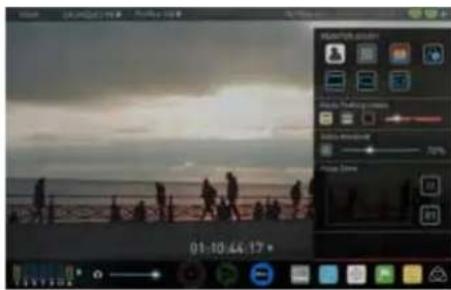
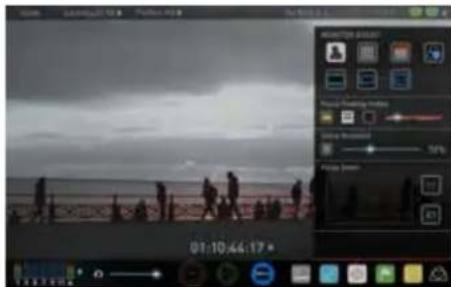
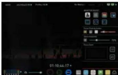
in focus. The parts of the image in focus are highlighted by the selected colour (can be adjusted by dragging the slider). There are a number of options for how peaking is displayed, it can overlayed over the colour video image, over a greyscale image or just show the peaking my selecting the corresponding icon.
Focus Assist Colour
Focus Assist Mono
Focus Assist Outline

You can change the focus peaking colors and modes from the Focus Assist Panel.
Zebra
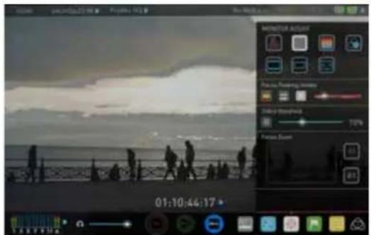
Zebra pattern show the parts of the image that are exposed + -5% of the target level set.
The Zebra threshold value can be adjusted by moving the slider left or right.
False Colour
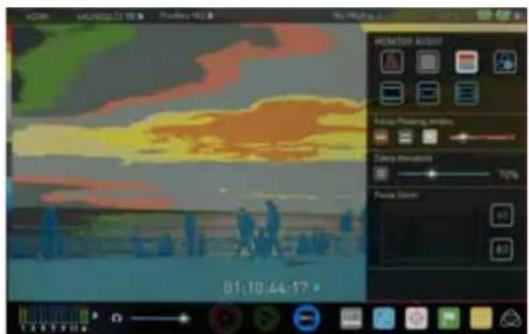
False Colour assigns different colors to areas of different brightness in the image. This gives a visualization of what is going on with exposure across the image. There is a scale on the left hand side, overexposed elements will display as red, and underexposed elements will display as blue.
False Colour Scale

natural_image
Dark, low-visibility image with indistinct shapes and colors, no readable text or symbolsTo help you determine the exposure range with more accuracy, please use the scale on the left hand side of the display.
9. Monitoring and Recording cont.
Blue Only Exposure
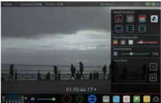
Blue only displays a greyscale image based on the blue channel of the input signal. This is useful to observe the noise content of a video image as sensor noise is most visible in this channel.
Cinema Guides / Safe Areas / Anamorphic De-Squeeze
AtomOS 6.5 introduced improved frame guides and safe areas. You can cycle through your required cine or TV frame guides by repeatedly pressing the guides icon. Action safe area and title safe areas can then be turned on and are proportional to the frame guides based on SMPTE standards.
How to use
To enable the Frame guides press the frame guide button to cycle through your chosen aspect ratio. The aspect ration markers are very useful with the 2 x Anamorphic De-Squeeze to preview and crops that could be made in post.
To turn on the safe area markers tap the Safe area button once for the Action area and again fore the title safe area.
Cinema Guides Safe Areas Anamorphic De-Squeeze


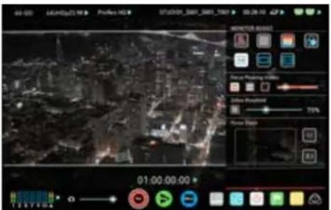
Cinema Guides Shown With Menu Overlays
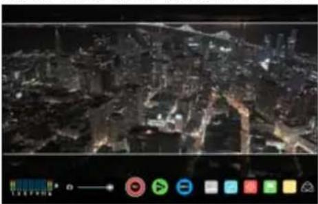
natural_image
Aerial night view of a cityscape with illuminated buildings and roads (no visible text or symbols)Cinema Guides Shown Without Menu Overlays

The Safe Area/Grid Lines will still be visible when tapping the center of the screen to hide the overlays.
Focus Assist Settings
From within the Waveform Monitoring menu, press the Settings icon to access the display settings for Focus Peaking, Zebra, False Colour and Blue Only Exposure.

Focus Assist Settings icon
To change the Focus Assist modes, press on the Colour, Mono or Outline icons and the display will update immediately.

Color Mono

Edges Only
(Depth of field focus tool)
The color of the Focus Assist can be changed by dragging the slider, the color selected will be reflected in the top line.

natural_image
Pure graphical icons showing a colorful square, two gray squares, and a green circular bar on a gray background (no text or symbols)The Zebra threshold value can be adjusted by moving the slider left or right. The threshold percentage will be shown on the right of the slider.


All of these settings will update without the need to close the settings.
Zoom
Zoom mode enables you to punch in and check critical focus
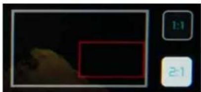
Toggle 1:1 to display 1:1 pixel mapping, the indicator box shows the location of the screen you are viewing.
4K 1:1 shows 1/4 of the 4K UHD image.
Toggle 2:1 to magnify the screen, the indicator box shows the location of the screen you are viewing, you can move the zoomed location by dragging across the screen or selecting a portion of the indicator box.
4K 2:1 shows 1/16 of the 4K UHD image.
natural_image
Close-up of a bird's head in dark environment with no visible text or symbols9. Monitoring and Recording cont.
SmartLog
SmartLog gives you the ability to tag your clips during recording (or playback, more on this later).
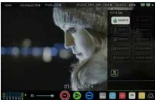
By the pressing the Favorite and Reject icons you can assign a "good clip" or "bad clip". This information can then be imported into a non-linear editing system to speed up the edit process. You can easily see which parts of your recording you have marked to keep or reject. Favorite clips can easily be built into a playlist in playback mode and these tagged sub clips can then be played out back to back.
AtomOS 6.4 introduced extended tags to allow you to be also make more specific tags that can help facilitate the edit.

SmartLog uses FCPX XML and can also be converted for Adobe and
Avid non-linear editors
How to use in Record and Monitor mode
To access tagging press the Cut and Tag on the home screen.

Cut and Tag icon
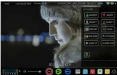
You can now see your video in the background and the Favorite and Reject icons along with other tags for marking clips whilst recording.
To use simply tap the desired tag to mark the in point and tap again to mark the outpoint.
Recording Mode: Cut And Tagging For Easy Clip Selection
Recording Mode: Clip Marked As A Good Take
How to use in Playback mode
To review and use the Cut and Tag feature in playback mode, press on the Play icon on the bottom of the screen.
Playback icon
From the Playback screen, hit the file name at the top centre of the screen to bring up the Playback file lister. Select a clip from the list by directly pressing it and it will become available for marking.
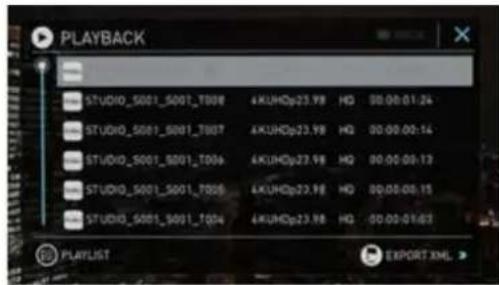
To access tagging press the Cut and Tag on the home screen.

Cut and Tag icon
The Favorite & Reject tags along with the other icons will appear on screen.
Press Play and when you see the section of the footage you would like to mark as good or bad, press Favorite or Reject and then press again to stop marking that section. Multiple other tags can be applied to your clips to provide Timecode accurate meta tags that can be exported to FCX XML.

natural_image
Simple optical lens diagram showing light path from left to right (no text or labels)
A green or red line will appear in the timeline scrubbing bar so you can identify the region that has been selected.
Removing tagged clips
To clear all marking point clips, press on the Reset icon.
Clear Tags
9. Monitoring and Recording cont.
Your final stage is to Export the tags to a FCPX XML file:
- Enter either the Playback List or the Media Information page
- On the bottom right hand side there is an icon Export XML
- Press this once
- You will be shown a please wait screen (the length of time will vary depending on your recording time and amount of flags applied)
- Then it will return you to the previous screen

EXPORT XML ICON

You can carry on recording but please remember if you add any additional tags you will need to export your XML file again.
Favorite Play list
When in Playback mode you have the option to create a play list of your Favorites. You can set this up by clicking on the playlist option in the Playback file lister. Cycle through the options until favorites is selected. You can then play these out in either order recorded or reverse. See the playpack section for more details on playlists on Page 37.
Display Option Menu

DISPLAY MENU
The Display menu icon on in the bottom corner of the menu bar accesses the Display options.
Tapping on the this icon brings up the following Display Options:
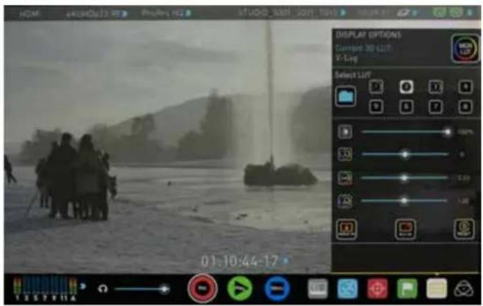
3DLUT
LUT or Look Up Table is a table that transforms the color response and as such adjusts the 'Look' of the input. 3DLUTs have a combination of three inputs defining the combination of R, G, and B values allowing for adjustment of not only color but also gamma and gamut.
LUTs can be used in a number of ways such as to preview the LOG output of a camera source in a specific colour gamut and gamma such as REC.709. This allows for easy preview and measurement of the image with in a color space that is used for final delivery.
LUTs can also be used more creatively to create a specific 'look' such as film stock emulation or to match cameras.
Atomos support 3DLUTs in the industry standard .CUBE format and provides 8 LUT memory slots for you load your LUTs in to. These can be loaded in from the Built in LUTs or from files created using 3rd party software.

1D LUTs are not supported and will need to be converted via 3rd party software to be imported.
To import LUTs into your Shogun Studio first copy the .CUBE files on to the SSD/HDD in your Master Caddy II using a computer.
To load a LUT select the desired slot and press on the blue file icon and then choose from off DISK or the BUILT-IN option. Navigate via touching through the disk file system to the LUT file to be uploaded, press on the name to highlight select the LUT and then again to import. Then wait for the LUT loading progress bar to complete.
The name of the currently selected 3D LUT is displayed at the top of the display menu panel. This LUT can then be applied to the display by pressing the monitor LUT icon.
MONITOR LUT ICON
The first touch will apply the LUT to 50% of the display source to allow a comparison of the two images.
The LUT can then be applied to the entire image with a second touch.
A third touch will turn the LUT off.
9. Monitoring and Recording cont.
Besides applying the LUT to the display for monitoring purposes, the LUT can also be applied to the HDMI/SDI outputs or baked into the recorded file. Options to control where the LUT is applied can be found on the input menu. See page 18.
If 3D LUT option is set to be applied to the recording it will bake the LUT look into the recording and this is a non-reversible process. It cannot be undone in Post so we advise you consider your workflow before the use of this option. When enabled, a RED MON LUT icon with flash in the top corner of the monitor and the 50/50 split cannot be activated to avoid any potential issues with the recorded content.

Waveform and Scopes are applied AFTER the LUT to allow you to preview the effect of the LUT on the image.
Under the LUT controls are a number of sliders. These allow the adjustment of the Display.
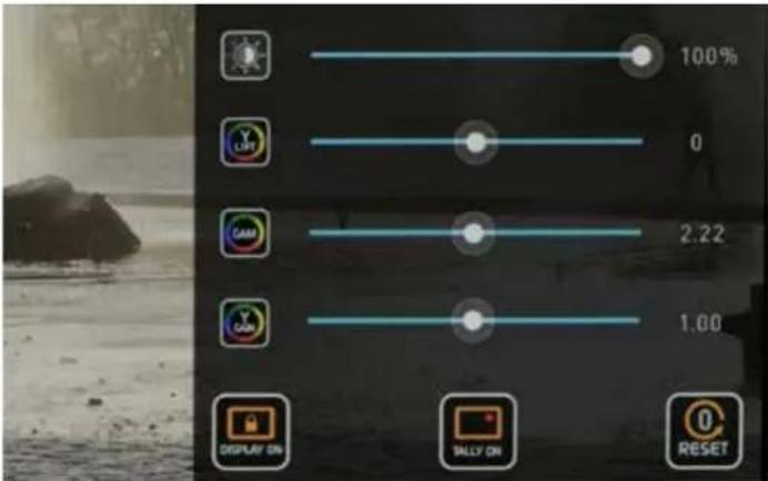
The First slider controls the brightness of the backlight of the display.
The other Sliders allow you to make adjustments of Gamma, Lift and Gain.

These affect the display only and have no impact on the recorded file or loop outs.

Reset all the screen adjustments

For accurate colour representation in the REC.709 color space an optional Spyder calibration unit is available. The package allows you to connect the calibrator and USB serial cable to a MAC or PC. The Atomos Calibration Software can then be used to set the screen to a REC709 gamut and gamma. It's recommended that you calibrate the monitor regularly as panel response will change over time.

Lock mode Display setting allows the SuperAtom IPS panel to be turned off when in lock mode. Activate the option by tapping the button and then tapping the Power on/off button on the side of the unit. Whilst activated you can touch the screen for a quick check. The tally light on the front of the unit will continue to function whilst the screen is off.

Tally Light On / Off Toggles the rear active recording indicator light.
9. Monitoring and Recording cont.
Atomos Anti-Shock Technology
Spinning disks are very reliable in a controlled environment where movement and vibration are minimal and within the capabilities of the devices. They are ideal for low-cost recording, but will suffer reduced performance if they are jolted or receive a sudden impact.
If a large enough shock occurs a break in the recording may occur. In this case the Shogun Studio will automatically start a new recording once the drive recovers.
This means that even if you suffer a momentary break in your recording, the video capture will continue without any intervention from you, the user.
It is obviously important for you to know that you have suffered from an interrupted recording and the user interface will display a warning (in the form of a Kangaroo sign) clearly in the top left hand corner of the display.


Skippy Warning
To remove "Skippy" warning, simply touch the icon and it will disappear.
File Recovery
The Shogun Studio continuously writes to disk while in recording mode. If the power fails or the drive is removed accidentally all but the last few seconds of the clip can be recovered
In the event of an interrupted recording, when you restart the Shogun Studio, or enter playback mode, you will be presented with a menu that gives you the option to recover immediately, or recover it later.
If you select recover later, every time you put the disk in, or start up the Shogun Studio, the same menu will appear to prompt you to recover the file that did not close properly.
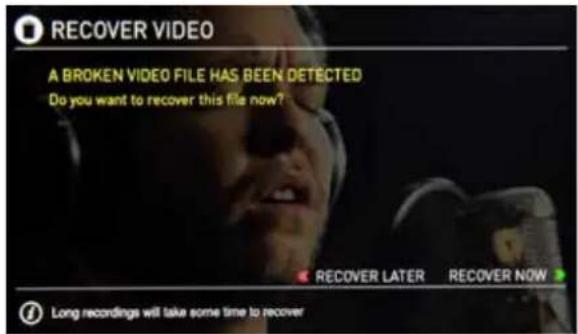
If the drive is broken, or has become corrupted, then we will not be able to recover the file and we recommend that you try third-party hard disk recovery software
10. Timecode
Using Timecode
Touching the Timecode display on the home screen, just above the three main controls (Rec, Play, Menu), will take you to the Timecode setup screen (this is also accessible by touching Menu and then Timecode)

Occupying the lower-centre part of the screen is the timecode display with controls to set the start-time of the timecode.
The Timecode modes supported are:
• HDMI (Embedded)
- SDI (Embedded)
- Record Run
• Time of Day
- Auto Restart
• LTC input (via GenLock BNC)
Cycle through these modes by touching the Timecode Source Selector.
SDI / HDMI embedded Timecode
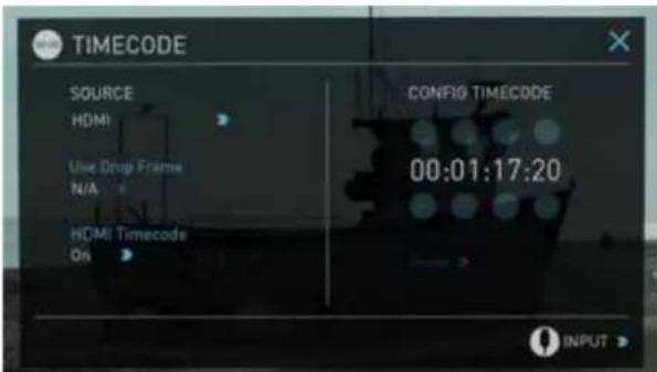
With this setting, the SDI or HDMI input will use the Timecode embedded in the input signal. The controls to adjust the Timecode value are disabled in this menu as you will need to adjust these on the camera. Note that not all HDMI sources embed Timecode.
Trigger from SDI or HDMI time code
If SDI or HDMI timecode is selected and the camera is in REC RUN mode, the user has the choice to start and stop recording remotely from the source camera SDI timecode.
To enable rolling Timecode Start/Stop functions, simply press the TC icon
shown here. When enabled, pressing the camera Record Stop/Start button will make the Shogun Studio start and stop record simultaneously as the timecode starts and stops.
When using the camera in Free Run timecode, the rolling timecode trigger might not work as expected. However, depending on the camera, you can trigger record function by the embedded flag/trigger in the SDI signal. Most higher end cameras have this functionality; if unsure contact us at support@atomos.com
Time of Day
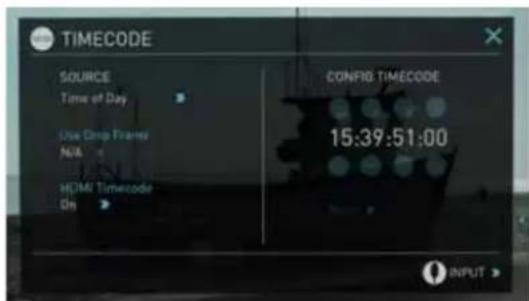
With this setting, each new clip that is created will contain embedded Timecode starting with the time of day when the recording is started. Please check that Shogun Studio clock has been set correctly.
This can be set in Menu > Date & Time
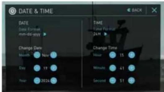
If recording is stopped and then restarted while in this mode, there will be a time gap between the last clip and the next one, equal to the length of time the Shogun Studio has been out of record.
In Time of Day mode, the controls on the Timecode Setup Screen for adjusting the start-point of the Shogun Studio Timecode are not available, as the Timecode is set by the Shogun Studio's internal clock.
10. Timecode cont.
LTC
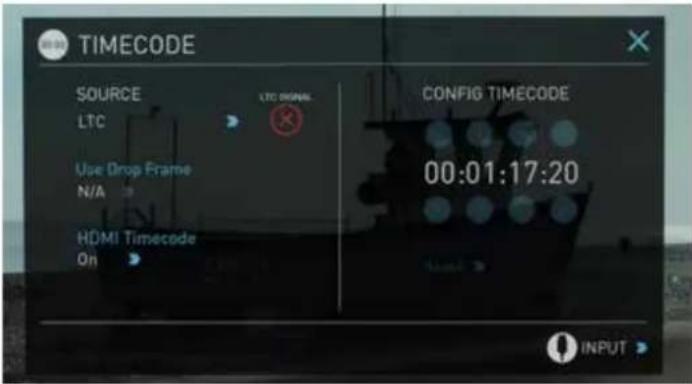
If LTC is selected then Timecode will be taken in via the LTC input. If no LTC signal is present the following icon is displayed and the unit will revert to SDI/HDMI Timecode
Auto Restart
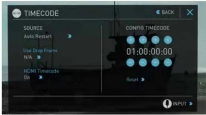
With this setting, the Timecode will be reset to the Timecode you have defined whenever you press record. All your clips will start with this same Timecode.

Please note that the LTC generator needs to be set to the same frame rate as the input video signal. If the LTC signal is looped through to the other channel then both recordings will have synchronized Timecode.

To adjust the Timecode use the "+" and "-" above and below the hour:minute:seconds sections
Record Run
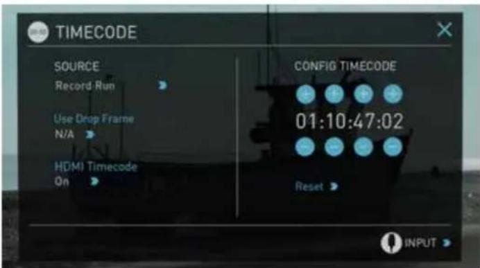
With this setting you set the starting Timecode for the first clip. The following clips will start at the frame immediately after the out point of the preceding clip. This will continue for all clips that follow. This is also known as continuous Timecode.
What is Pulldown?
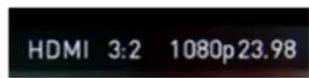
Many professional and consumer cameras available today do not send true 1080p24, 1080p23.98, 1080p25, 1080p29.97 or 1080p30 signals down their SDI or HDMI outputs.

Instead they send 1080i59.94 in NTSC regions (eg USA, Japan), and 1080i50 in PAL regions (eg Europe)
In order to convert the signal from the internal recording format to 1080i5994 or 1080i50, they use a process called 3:2 or 2:2 pulldown.

Pulldown is only applicable to interlaced HD signals, not 4K
| Camera Setting Pulldown Shogun Studio | ||
| Receives | ||
| 1080p23.98 3:2 1080i59.94 | ||
| 1080p24 3:2 1080i60 | ||
| 1080p25 2:2 1080i50 | ||
| 1080p29.97 2:2 1080i59.94 | ||
| 1080p30 2:2 1080i60 | ||
You will, of course, want the Shogun Studio to record the actual frame rate such as 1080p23.98, not the 1080i59.94 to disk. In many cases, it is not possible for the Shogun Studio to detect when pulldown has been applied to the video, so you will have to set the correct mode of removal on the Shogun Studio to match the setup of your camera.
With some cameras, the Shogun Studio can detect and remove the pulldown automatically, in which case the mode you expect (eg 1080p23.98) will display on the Shogun Studio and you will not have to do anything further.
If there is no input detected, then toggle the input by pressing the screen until you see the input you wish to record.

Atomos is adding auto-detection support for more cameras, please check for firmware updates regularly at www.atomos.com
1080p23.98 or 1080p24
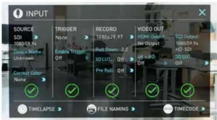
If you have set 1080p23.98 or 1080p24 in your camera and your Shogun Studio displays 1080i59.94 or 1080i60, then you can easily remove the pulldown by following these steps:
- Select the Input Menu from the top Left and toggle the blue arrow underneath Record repeatedly until you see 1080p23.98 (or 1080p24) displayed. You may not get a green tick in this column immediately.
- Your Shogun Studio needs to analyse the video for about 1 second, in order to detect the pulldown sequence and remove it.
- If it is not automatically detected after 1 second, wave your hand from side to side in front of the lens, or wave the camera from side to side for a few seconds. The Shogun Studio will detect the pulldown cadence in the movement, and you will see a green tick along with the video displayed on the screen.
- 3:2 pulldown detection is difficult, if not impossible to detect on completely still video. This is why you should wave your hand in front of the lens.

3:2 pulldown detection is difficult, if not impossible to detect on completely still video. This is why you should wave your hand in front of the lens.

If you lose the input detection – for example you unplug the SDI cable or go to Playback mode, you will need to wave your hand or the camera again, when the signal is restored to the Shogun Studio.

Some cameras use a variant of pulldown removal, for example Panasonic Advanced pulldown. The Shogun Studio does NOT support this format, and it will not be detected.

Standard Panasonic pulldown is supported, ensure in the Panasonic camera settings that pulldown is not set to Advanced.
1080p25, 1080p29.97 or 1080p30
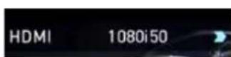
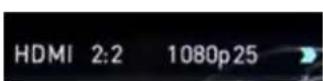
For these modes, simply press the blue arrow underneath Record on the input menu repeatedly until your 1080p desired format is displayed. There is no need to wave your hand or the camera, as 2:2 pulldown removal does not require moving video.
Record Modes:
In standard record mode there are a number of features that are implemented with safety in mind. Source Drop – If a connection is lost due to the cable being pulled out from either side of the signal path the recording will stop and close that file. As soon as you plug the cable back in it will start recording a new file with out having to press record again.
If AC power is lost the recorded files are still safe. Once the unit is powered back up it will detect the broken file and ask you to repair the clip now or later. With a power loss there will be some loss of content. Typically the last 5-10 seconds of footage.
Alongside the standard recording functionality additional Record Modes are available in the form of Pre Roll, Time Lapse, Dual Record & Continuous Record.
Pre Roll Record
Pre Roll: Off
This option is enabled from the input menu under Record section. With this option turned on you will see a white circular arrow around the record button and a red Pre Roll icon will flash in the top left hand corner. Whilst enabled the input is constantly been recorded with approximately the last 8 seconds in HD and 2-3 seconds in 4k being cached into memory. The frame rate and codec selected will affect the number of seconds being cached for pre roll. Using a lower bit rate codec setting and shooting at lower frame rate will increase the length of pre-roll.
When the record button is pressed or trigger is sent, the buffered pre-roll data in memory will be written out to the start of the recording. This means if you are few seconds slow hitting the record button when something interesting happens you will still capture the shot.

When Pre Roll mode activated the Recorder is constantly caching frames internally to the unit and as such any feature that can not be changed whilst recording is not available. This includes audio channel select, 3D LUT record, codec, disk options etc. Time Lapse record is also disables when Pre Roll is enabled.
Time Lapse
Video Time lapse provides the ability to create seamless time lapses with out capturing individual images that require compiling in post. Utilizing video also takes away the wear on you camera shutter that can be expensive to replace if you are doing lots of time-lapse work.
This function is accessed via the input menu and then selecting the Time Lapse option in the bottom left of this menu.
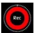
The Time Lapse Recording menu will then open to provide you with a number of options.
Time Lapse On/off – this allows you to turn on time lapse recoding mode and when an input is present the record button will white have dashed lines around it like a clock face.

When time lapse is enabled Pre-Roll is cannot be enabled.
A sequence entry will already be present in the menu and to edit the entry simply touch to highlight it and then tap on the blue arrow at right hand side of the entry. This opens the Edit Sequence menu where you can alter the following settings:
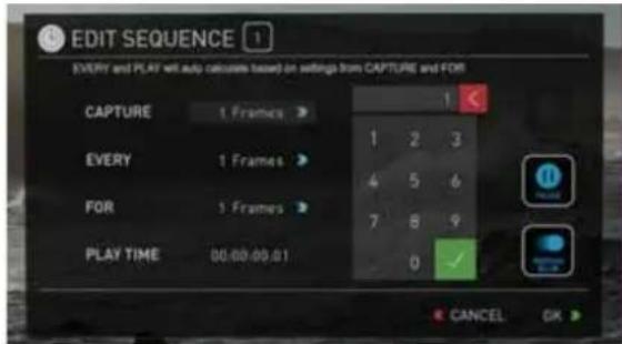
Capture – Specifies the number of sequential frames to be captured. Every – Specifies the frequency of the capture.
For – defines the amount of time to repeat the process for this entry. Play time – this will display the playback duration for the above settings.
Times can be specified in Frames, Second, minutes and hours

The number of frames specified for 'Capture' will capture in quick succession at the specified time – so for example if it is set to capture 5 frames every 1 minute. The 5 frames will be captured sequentially at the start of every minute. The frames captured will not be evenly spread across the minute.
When setting up a sequence you can also choose to add Motion blur to an entry. With this option enabled the behavior is slightly different. The number of frames specified in 'Capture' are added together with the resulting single summed frame being recorded. You will notice that the Playtime decreases when you have motion blur turned on as multiple frames are been summed to a single frame instead of been recorded sequentially. When motion blur is on the maximum setting for 'Capture' is 64 frames.
The sequence setting for the current entry is saved when you lap the OK button.
The Add icon allows you to add additional entries to your time lapse sequence. Up to 10 sequences can be added will automatically flow in to each other.
Pause sequences can also be set up to allow the recording to be paused for a specified amount of time with no frames captured.
After the required number of sequence entries have been set up an option to apply a smooth transition can be selected. This will apply a ramp between the different sequence entries to improve the blend between differing capture settings. The icon will be white when the option is selected.
The Schedule start icon allows you to utilize the internal clock of your Shogun Studio to set a specific time for the start of the time-lapse sequence. Pressing the icon will activate the Schedule start mode and the icon will turn white with a default time of 00:00:00 will appear with a blue arrow. Press the blue arrow to adjust the starting time For the Scheduled start to be accurate please check the Date & Time settings are correct. They can be accessed via the blue Menu button at the bottom centre of the GUI and Selecting the Date & Time icon to adjust them if required.
With Schedule Start activated when you press the record button a red icon will flash in the top corner, along with the red record border and tally light and a count down to the scheduled start will be displayed.
Continuous Record Mode – This option allows a single input to record continuously, starting with the media on Recorder Channel 1 and changing to the media Recorder Channel 2 when it is full.

A loop out of Recorder Channel 1 into the input of recorder Channel 2 needs to be connected with an SDI or HDMI cable.
To activate continuous record mode:
Press the Recorder Channel 1 icon and select Continuous Record Mode to enable this option. Once activated, Channel 1 becomes the Master and Channel 2 becomes the Slave.
Recording will start on Channel 1 which will show a Red recording border around the screen. Channel 2 will show a green border. It is safe to remove the disk when the green border is displayed, but a disk must be inserted before the first drive is full. Once the disk on Recorder Channel 1 is full, it will automatically start recording on Channel 2 and this will now display a red border. Once the green border is showing on Channel 1, the disk is safe to remove.

Please note that for to ensure no content is lost there is a 2 sec recording buffer overlap during continuous record.
Dual record Mode – Dual record mode allows an input from Recorder Channel 1 to be simultaneously recorded on both channels.
To activate Dual record mode:

Press the Recorder Channel 1 icon and select Dual Record Mode to enable this option. Once activated, Channel 1 becomes the Master and Channel 2 becomes the Slave.
When record is pressed on Recorder Channel 1 then Recorder Channel 2 will also start to record. The dual record mode feature allows for both multi codec, multi stream and multi resolution recording.

Whilst in Dual record mode although Channel one acts as the master to control Channel 2 separate inputs can be connected to each Channel input allowing synchronised recording of separate inputs. Timecode will not necessarily be synchronized. Timecode needs to be synced either at the cameras or through use of LTC Timecode setup
Multi Codec/Resolution Recording – This provides the benefit of recording two versions of the same input using different codecs The loop out function also allows for dual resolution 4K & HD versions of the same content to be recorded. This can be achieved by turning on the 4K to HD down scale via the input menu of the GUI. This allows for a full resolution 4k master and lower resolution proxy of the same recording. Other combinations of ProRes, DNxHD or DNxHR can be recorded simultaneously, e.g;
4K ProRes HQ & 1080p ProRes LT
4K DNxHR HQ & 1080p DNxHD 36
4K Prores HQ & 4K DNxHR HQ
These simultaneous record features are achieved via either the use of an external routing matrix e.g. SDI router or via connection from the Loop out of Channel 1 to Channel 2 or vice versa. The Trigger on the SDI or the HDMI will be passed through the loop which means that when record is pressed on the camera, both units will start to record. This can also be used in conjunction with Dual Record mode to allow control via the touch screen. When using the Loop out feature in Simultaneous record you have the added benefit to convert HDMI to SDI and apply a LUT burnt in to the Slave Recorder Channel to create instant dailies that can be reviewed straight off the drive using a stand alone Shogun or Ninja Assassin unit.
Playback Mode
One of the key elements of the Shogun Studio REC PLAY MONITOR EDIT is the ability to utilize the monitor recorder as a play back and play out device for the content that has been recorded whilst maintaining the same visually lossless high quality images.
Pressing the Play button will turn your put the device into play back mode and the last clip recorded on to the drive will instantly begin to playback.
Once within Play mode the same feature Monitoring tool set is available allowing you to analyse the content. This is key for establishing if takes are out of focus, lighting has changed or previewing content with LUTs applied.
Clips can be selected for play back by tapping the clip name at the top of the screen, with the ability to skip to the next or previous clip via the on screen controls.
Once the file name had been pressed a menu displaying the clips available on the drive will be displayed showing clip name (with Scene shot Take numbers) as well as resolution, codec and duration. Tapping to highlight a clip will show a preview of the first frame in the back ground and tapping again will play this clip or by pressing the play button.

When the playback content list menu is open play back will automatically stop.
Whilst a Clip is playing you can play or pause the clip by using the main play button in the center of the menu controls at the bottom of the screen. Above the Monitor tools icons are also a Play and Pause button along with additional play back controls.

By tapping this icon you can put the clip in to loop play back. In and out markers for loop you can be placed and cleared using the following buttons :
Press to turn on and mark loop starting point, press again to remove both in and out loop markers. When loop in is pressed the loop out point will automatically be set to the end of the clip.
Press to place the loop out marker and replace the marker at the end of the clip, press again to reset it to the end of the clip.


These are accessed via the green flag tagging menu


Whilst a clip is playing these buttons have the ability to play the clip back at 2 x or 4x speeds both forward and in reverse.


Whilst a clip is Paused these buttons have the ability to step the clip by 1 second either forward or reverse to give you chance to analyse the clip in more detail, this is especially useful when combined with the 2:1 zoom function.
Playlist
To increase the functionality and flexibility of the playback mode there is also the ability to create a Playlist.
To start to build a Playlist press on the file name in the top menu and
open the content list. Then press the Playlist button, which will turn green and reveal the options available.

It's important to note that all clips in the play list must be in the same codec, resolution and frame rate.
The Order Arrow allows you to choose order in which clips playback. The clips are stored based on the order they were recorded with the last clip recorded at the top of the list. You can either play down the list (newest to oldest) or up the list (sequential order).

This icon can be pressed to scroll through the play list options. All will play all clips on the disk.

Will play only the clips that are tagged as favorites.
Will allow the clips for the playlist to be selected using the tick boxes.

Will include the favorites and also allow the ability to selected additional clips to be played back.

The duration of each clip is combined together and are shown on the scrub bar in play pack controls. A white vertical line indicates the start and end points and clips will seamlessly playback across those selected to be in the play lost.
The Genlock input can accept a standard composite video signal such as a Black Burs bi-level reference signal and Tri-level reference signal. Once connected, playback output is synchronized to this common reference source. This can be done across multiple units and ensures proper deck use with Switchers and Vision Mixers in live events & mobile production studios. Having all the inputs synchronized at the video Switcher allows the Switcher to operate glitch free when making transitions, cuts, and graphic overlays between those synchronized.
Metadata tagging and cut edits
In playback mode the ability to tag clips is extended beyond simply applying a single tag to a clip. With a clip selected and either ready to play or playing you can set in and out points for tags. This allows you to make Timecode accurate clips and even subclips with those tags. The tagscan be applied by tapping the appropriate icon to mark in and out points at the desired play head positions.
This can be done whilst the clip is playing or by simply dragging the scrub bar toto the position wanted. Favorites will be displayed as agree section on the scrub bar, a red section indicates rejected areas and white is used for the other tags.

natural_image
Simple optical setup with a lens and colored beam (no text or symbols)Creating smart cut tags via this method is non destructive to the clips and the information can be exported to a separate XML file. These markers are ideal for creating an Edit Decision List (EDL) to go with the clips. This allows for edit preparation to take place on set, whilst traveling or with a client to save time in post production.

Creates and saves the metadata tags in to XML in FCPX format.
Tapping reset will remove the all tags from the current clip.
Favorite Play list
The cut tag edit points can be combined with the favorites play list allowing the in and out points that have been created with in the clip using the favorites flag to be used as sub clips with in a play list. This means that if in and out points have been marked on a clip only those section of the clip will play when used in a favorites or combined Play list. Close attention should be place to the order icon as this also relates to the sub clips in that with the run down order will play the last sub clip first in the play list.

Whilst a playlist is in operation further metadata tags can not longer be applied to these clips.
Shogun Studio additional control
Shogun Studio can either be controlled via the lightning fast AtomOS touch screen interface, which allows you to control each device individually, via the RJ45 connection to take advantage of Advanced Multimedia (AMP) protocol commands or via 9 pin D-sub connection of RS422 Machine control. Using the display lock function the touch screen can be locked to allow for only remote control operation of the Shogun Studio
RS422 – Each recorder channel has a 9 pin D-Sub connection that can be connected to a controller or other source to control the basic functionality of recorder channel. At launch the Shogun Studio will offer support for basic transport controls:
REC – will activate record as well as switch back to Record mode from Play mode
STOP – Will operate in both Record and Playback Mode
PLAY – will activate play back or switch to Playback mode from Record mode
Reverse Play – will Activate reverse play at normal speed.
FFWD – will activate fast forward at 2 x speed
RWD – will activate fast Rewind at 2 x speed
In conjunction with a Jog shuttle dial the scrubbing function will be utilized to move the play head up and down the duration of the clip or play list.
Advanced Multimedia Protocol - AMP
Setting up AMP
The control of the Shogun Studio via AMP requires and Cat5 or above cable to be connected to the RJ45 connector on the rear of the of the Shogun Studio. In term this needs to be connected to the same network as the controlling device.
Setting the IP address
To assign the IP address to the Shogun Studio press the blue Menu button and the select the Network Configuration settings icon. By default the Shogun Studio is set to DHCP and so will be assigned an address via the existing network infrastructure.
flowchart
graph LR
    A["Menu"] --> B["Server Icon"]
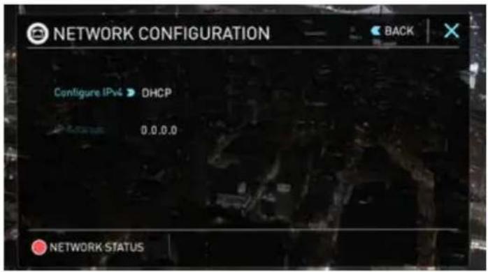
Alternatively a Static IP address can be set for each recorder channel in the Shogun Studio. Press the blue Menu button and then press the Network Configuration settings button then press on DHCP and the IP address input will appear.
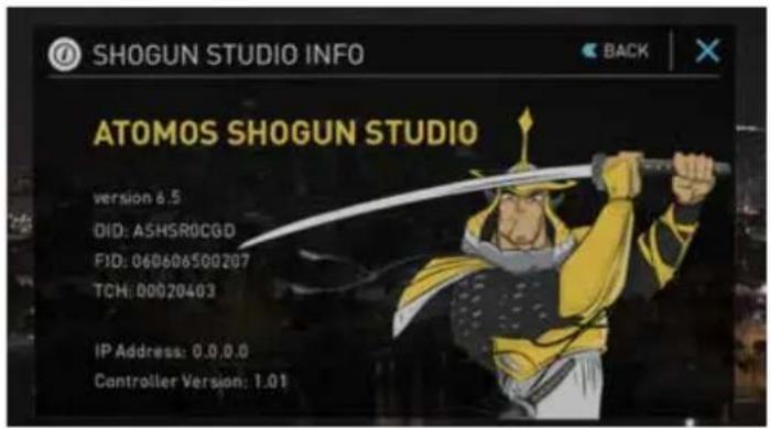

It's important to maintain accuracy with the required IP and Subnet as a single incorrect digit will mean that the unit will no respond to the required commands.
Supported Amp (Advanced Media Protocol) Commands
| Name Code Description | ||
| Stop 2X.00 Stops any playback or recording | ||
| Play 2X.01 Places the unit in play mode and begins playback | ||
| Record 2X.02 Places the unit in record mode and begins recording | ||
| Fast Forward 20.10 Fast forward at 16x playback rate | ||
| Jog Forward 2X.11 Step forward specified number of frames | ||
| Variable Forward 2X.12 Fast forward at specified rate | ||
| Shuttle Forward 2X.13 Fast forward at specified rate | ||
| Rewind 20.20 Rewind at 16x speed | ||
| Jog Reverse 2X.21 Step back ward specified number of frames | ||
| Variable Reverse 2X.22 Rewind at specified rate | ||
| Shuttle Reverse 2X.23 Rewind at specified rate | ||
| Set Loop Playback Mode 41.42 Enable or Disable loop mode | ||
| ID Count Request A0.26 | Return the number of files on disk | |
| List First ID | AX.14 Return the filename of first file on disk | |
| List Next ID | AX.15 Return filename of next file on disk | |
| In Preset | 4X.14 Cue up the specified filename | |
14. Connecting and Editing
Connect
To access and edit your recorded material, connect the Master Caddy Docking Station to a Mac® or Windows® editing workstation via USB 2.0 or USB 3.0.
Eject the Master Caddy from your Shogun Studio and insert it into the Docking Station. After a short wait, the recorded video will be accessible to the target computer via a standard disk (exFAT) file system.
NLE supported
We have chosen the Apple ProRes®, Avid DNxHD® and Avid DNxHR® codecs as they are both not only visually lossless, but also edit-ready formats. All major NLEs support ProRes and DNxHD/DNxHR.
• Final Cut Pro (version 7)
- Final Cut X
- Adobe CS5 (with 5.51 update or later)
• EDIUS 6
- Sony Vegas 10
• Lightworks
- Avid Media Composer 6 (version 8.3 or later for DNxHR)
Avid DNxHD® / DNxHR® support requires online activation.
ExFAT compatibility
The Shogun Studio formats your disk as exFAT. We have chosen this file system to overcome the 4GB file limitation of FAT32 and keep compatibility on both Windows and MAC OS.
The Operating Systems that support exFAT are:
- Windows XP - install the following update: http://www.microsoft.com/download/en/details.aspx?id=19364
• Windows Vista - install SP1 or higher
• Windows 7 & 8 (32/64bit) - Snow Leopard 10.6.5 or higher
- Lion 10.7
- Mountain Lion 10.8
• Mavericks 10.9 and above
The Master Caddy Docking Station is a sophisticated device supporting two different data interfaces: USB 2 and USB 3. When using the Master Caddy Docking Station you may need to connect both USB connectors. This is because when it has to power a disk drive and its interface electronics, the Docking Station may consume more power than is available from a single USB port.
Transferring Files
Now your docking station is connected and your disk is recognized by your operating system, you can edit directly from the drive or copy the files to your own storage.
Windows
Open the disk in My Computer > Select all the files or just the ones you wish to transfer, copy and paste them to your desired location. (ctrl+c copy, ctrl+v paste).
Mac OS
Your Shogun Studio disk will show in Finder. Select the files you wish to transfer, drag the files to your desired location or use the copy and paste commands. (COMMAND + C copy, COMMAND + V paste).
If you have used a FAT32 formatted disk in the Shogun Studio this will have a folder structure Scene, Shot, Take. This will mean you either transfer all the folders or utilize the Windows Search or MACs automate program to transfer just the .mov files. There are instructions on this in our knowledge base; visit www.atomos.com/support for more info.
USB 2.0 and 3.0 compatible Connect to Laptop/
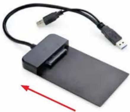
natural_image
Black USB flash drive with attached cable and rectangular base, no visible text or symbolsAttach Master Caddy
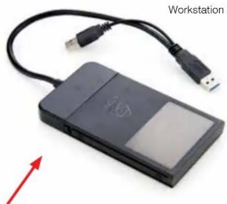
natural_image
Black electronic device with USB cable and a labeled Workstation (no text on device body)Ensure disk is properly attached
14. Connecting and Editing cont.
Importing
Final Cut Pro (version 7), Final Cut X, Adobe CS5 (with 5.51 update), EDIUS 6, Sony Vegas 10, Lightworks and Avid Media Composer 6 support imported files from your Shogun Studio disk.
Importing Shogun Studio footage into Final Cut Pro
You can import Shogun Studio footage into Final Cut Pro (FCP) in just a few simple steps.
First, connect the Shogun Studio Docking Station to your Apple Mac using the USB 2.0 or USB 3.0 port. Insert the Shogun Studio Master Caddy containing the disk with your footage into the Docking Station and you will see the drive appear in your Finder window.
Start FCP and open your project (or start a new one).
The screen will look like this:

Go to the File menu and select Import > Media
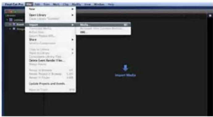
FCP will show you a "browse" window. Look for the Shogun Studio drive, and click on it.
You'll see the folders in the Shogun Studio drive. Select the folder containing the footage you want to import:
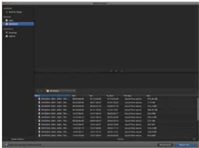
Click on Import All or Import Selected, individual clips can be selected. Choose the Event you wish to import the footage into, or create a new event.
Select Import:
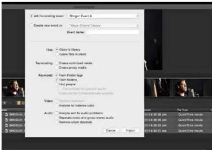
Your Scene, Shot and Take files now appear in the project window, ready for use in your FCP project.
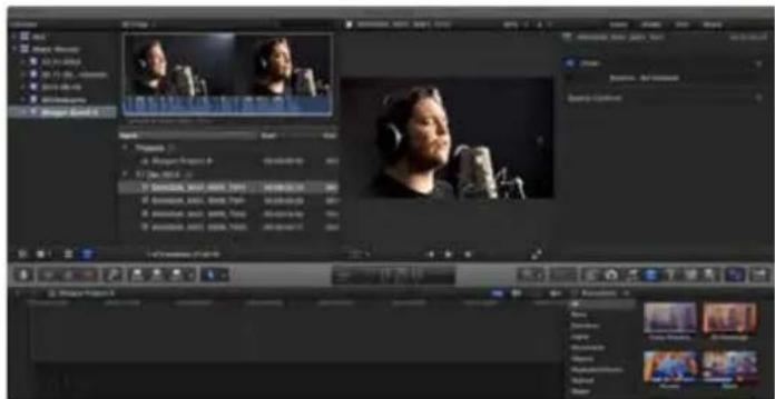
14. Connecting and Editing cont.
SmartLog with FCP X
Prior to importing the XML files into FCP X, ensure that:
- You have exported XML whilst the drive is in your Shogun Studio
- You have connected your Master Caddy Docking Station and inserted your Master Caddy into the Dock
- You are using an operating system that supports ExFAT
- Your QuickTime version is up to date
• FCP X is the latest version
There are 2 ways to import the XML file:
- Directly from the docked hard drive
- Manually into FCP X
1. Automatic Import
- Open Finder
- Select the drive (in this example it is EXCVIDEO)
- Double-click the unitname.FCPXML file
- This will open FCP X and import the .xml file
FCP X will make a event of the disk name and reference all the footage in that event.
You will notice that on the clips you have added Smart Tags too, with Green and Red indicating Favorite and Reject.
You can sort these by using the pull-down menu to show favorites. This will show all the individual favorites as separate clips in the Event Viewer.
2. Manual
- Open FCP X
- Create a New Project (or you can use an existing project); in this example it is called XML Import
- Select File, Import, XML
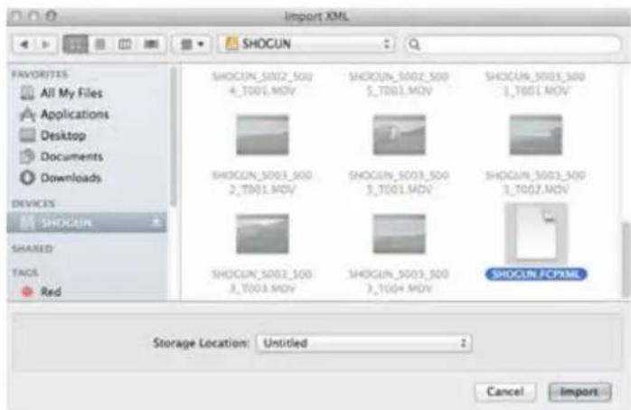
- Select the Shogun Studio drive under Devices (in this example it is called EXCVIDEO)
- Choose the unitname.FCPXML, select Import
The XML will import

Once imported you can expand the clip and you will see the Favorite and Reject tags. You can also filter the view to only see favorite, etc.
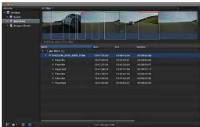
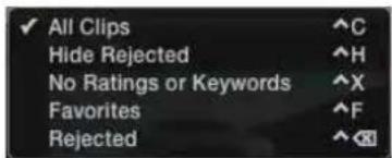
Updating AtomOS (Firmware)
The Shogun Studio uses it's own version of AtomOS and you will need to apply this to both recorder channels individually by placing the new ATOMSHS.FW file in the root of your drive, placing this in drive bay before turning the device on. You can update both units at the same time but this will require a disk to be in the drive bay of each unit.
From time to time we will issue software updates for your Shogun Studio. To update the firmware (that's the software that runs inside your Shogun Studio), there is a simple procedure you have to follow.
- Go to www.atomos.com/support
-
Locate and download the firmware upgrade
-
Extract the file ATOMSHS.FW from the firmware zip file.
- Copy ATOMSHS.FW onto a drive in a Master Caddy.
a. Atomos recommends you use a freshly formatted known good disk.
b. Always format your drives in the Shogun Studio. The Shogun Studio formats the drive for optimal performance for Video.
c. Ensure that the firmware update file is on the root of the drive, and not in a folder on the drive.
- Power down your Shogun Studio.
- Insert the Master Caddy with the ATOMSHS.FW file.
- Power up your Shogun Studio with a short press of the Power Button.
- Watch the screen. The Atomos logo will appear, and then be replaced with a Please Wait logo and after a few seconds the firmware upgrade will start.
- The firmware upgrade will take up to a few minutes.
- When the firmware upgrade is finished, the Shogun Studio will:
a. Delete ATOMSHS.FW from the drive.
b. Power itself down.
- Turn on your Shogun Studio again with a short press of the Power Button located on the side.
- When the Shogun Studio has booted, Press "MENU" and then "Shogun Studio Info" and check that the version number is the version expected.
Please make sure that the FW file is not renamed when you computer unpacks the ZIP file. If you have other FW in the same folder the file may become names ATOMSHS-2.FW and the update will not work.
Firmware update for Shogun Studio Controller
Occasionally the Shogun Studio's controller will also need to be updated this is achieved via the USB port on the rear of the unit and placing the relevant file in the Root of a FAT32 formatted USB flash drive. Please see the release notes for specifics on how to conduct this update.
IMPORTANT: Problems when installing AtomOS
Very occasionally, the firmware update process can go wrong. This might be because of an incomplete or corrupted download.
In the unlikely event of your Shogun Studio becoming unresponsive, there is a built-in recovery mechanism.
All you have to do is press and hold the on/off button for 10 seconds. If you do this your Shogun Studio will revert to its factory condition, and you will be able to retry the firmware update later (taking due precautions to identify and remove possible reasons for the failure of the previous attempt).
Please ensure that you do not interrupt your Shogun Studio while its firmware is upgrading. You will see a progress bar to the lower half of the screen, When it is fished, the Shogun Studio will restart and you will be able to use the device as normal. This process can take up to 7 minutes.
| SPECIFICATIONS | SHOGUN STUDIO | |
| Weight & dimensions | ||
| Weight | 5.0kg / 11lb | |
| Rack height | 3RU | |
| Rack mounting | Removable rack ears | |
| Dimensions (W x H x D mm) | 447 x 152 x 251mm, 17.6 x 6.0 x 9.9" (without rack cars)490 x 152 x 251mm, 19.3 x 6.0 x 9.9" (with rack ears) | |
| Construction | Steel construction for durability | |
| Cooling | Actively controlled fan with heat sinks | |
| Power | ||
| Operating power | 20 - 60W | |
| Redundant PSU | Yes | |
| Compatible batteries | No | |
| Input voltage (battery) | - | |
| DC Out | No | |
| Continuous power* Patent pending | - | |
| Touchscreen | ||
| Size | 7.1" | |
| Resolution | 1920 x 1200 | |
| PPI | 325 | |
| Aspect ratio | 16.9 native | |
| Color standard | Rec.709 HDTV | |
| Look up table (LUT) support | 3D LUT (.cube file format) | |
| Technology | SuperAtom IPS panel (capacitive touch), calibration to Rec.709 with optional Alomos Spyder | |
| Video analysis tools | Luma waveform, RGB parade, Vectorscope, Vectorscope zoom | |
| Calibration | Calibration in factory to Rec.709, in field calibration with optional Spyder | |
| Video Input/loop out | ||
| HDMI | 1 x HDMI (1.4b) per channel | |
| SDI | 1 x 4K-SDI 12G/6G or HD-SDI 3G/1.5G (SMPTE) per channel | |
| Signal | Uncompressed true 10-bit or 8-bit 422 (camera dependent) | |
| Video output (play out) | ||
| HDMI | 1 x HDMI (1.4b) per channel | |
| SDI | 1x 4K-SDI 12G/6G or HD-SDI 3G/1.5G (SMPTE) per channel | |
| Signal | Uncompressed true 10-bit or 8-bit 422 ( playback file dependent) | |
| Supported formats (Record & Playback) | ||
| 4K - DCI RAW 4096x2160 to Supported cameras; Sony FS700, FS7 Canon C300MKII, C500 | Apple ProResHQ, 422, LT | DNxHRHQX, HQ, SQ, LB |
| 4K-UHD 3840x2160 8/10-bit 4:2:2 to | Apple ProResHQ, 422, LT | DNxHRHQX, HQ, SQ, LB |
| 1920x1080 8/10-bit 4:2:2 to | Apple ProResHQ, 422, LT | DNxHD220x, 220, 145, 36 |
| 1280x720 8/10-bit 4:2:2 to | Apple ProResHQ, 422, LT | DNxHD220x, 220, 145, 36 |
| Onboard processing | ||
| Pulldown removal | 24/25/30pSF > 24/25/30p (2:2 pulldown)60i > 24p (3:2 pulldown) | |
| HDMI <> SDI conversion | Yes - Always on | |
| 4K - UHD to HD downscale | On HDMI/SDI loop out (Rec & Playout) | |
| SPECIFICATIONS | SHOGUN STUDIO |
| Audio In/out (48kHz PCM audio) | |
| HDMI | 2 or 8ch 24-bit, camera dependent |
| SDI | 12ch 48kHz 24-bit |
| Analogue audio | 2 x XLR in & 2 x XLR out on roar por record channel.Mic or line level with phantom 48V |
| Processing | Gain control on line in & headphone output |
| Maximum audio quality | 24-bit, 48kHz |
| Audio delay | Delay setting +1 to 99 frames |
| Remote control | |
| HDMI | Auto HDMI TriggerSupported Protocols - Canon, Sony, Atomos Open Standard |
| SDI | SDI trigger camera selectable |
| RS422 | RS422 machine control |
| AMP | Ethernet RJ45 10/100 |
| Serial | Calibration (front) |
| Timecode | |
| HDMI Embedded Timecode from camera or video device | |
| SDI Embedded Timecode from camera or video device | |
| LTC In Yes (LTC loop back) | |
| GenLock In Yes (GenLock loop back) | |
| Playback | |
| Playlist | Yes (run down or reverse order) for selected, favorite or all clips |
| Playback options | Loop in & out markers |
| Recording | |
| Dual channel | Record 4K masters with HD proxies. Record both ProRes & DNxHR versions, independent dual channel record. |
| Continuous record | Single channel 4K / HD recording automatically switches between drive when at capacity |
| Pre-roll record | Yes (HD 8s, 4K 2s) |
| Custom time lapse | Yes (Key frameable up to 10 video and single frame Intervals, can be triggered from internal clock). |
| Meta data tagging | Yes (10 tags available) |
| Recording media | |
| Drive slots 2 (1 per record channel) | |
| Drive connection types SATA | |
| Supported media (Approved List Only) | 4K / HD (50/60/120p*)CFast 2.0, SSD 2.5", HDD (HD 50/60 only - 7,200 up to 1080p60)HDCfast 1.0, SSD 2.5", HDD (5,400 up to 1080p30) |
| Master caddy case | Master Caddy II (included)75mm x 105mm x 12mm |
| Master caddy dock | 2.5" SATA to USB 2.0/3.0 |
| Supported applications | FCPX/FCP7+ / Media Composer 5.0+ / Premiere 5.5+, EDIUS 6.0+ / Vegas Pro 10+ / Lightworks / Autodesk Smoke 2015 |
| XML support | FCPX XML native, FCP7 supported with conversion (Adobe compatible) |
| Accessories Included | Shogun Studio unit, 2x Rack cars with screws, 5x Master II Caddies, 4x Rubber feet, 2x Large rubber feel, 2x IEC power cable, 1x Screen cleaning cloth |
| Optional extras | Master Caddy II x 5, Spyder calibration |
| Warranty | 1 year. Extended to 3 years on product registration |
Specifications correct at time of printing E&OE
Construction note:
Your Shogun Studio is designed to operate in ambient temperatures up to 45^ C/113°F. It features a heat pipe design with a silent fan to circulate air and remove excess heat from the rear vents.
If you wish to extend the temperature of operation in high temperature conditions, you can choose an SSD drive, and set the TFT brightness to a minimum.
Atomos (HQ)
29 Nott Street, Port Melbourne
Victoria 3207 Australia
Tel: 1300 ATOMOS
www.atomos.com
Have you registered your Shogun Studio yet?
Register now to receive communication on all future updates
Web: www.atomos.com Sales: sales@atomos.com Support: support@atomos.com
- Warranty & Conditions 3
- Introduction
- What you also need 6
- Mounting disks in the Master Caddy II 8
- Attaching Rack Ears and Feet 9
- Connecting and powering up 10
- Shogun Studio connections
- Master Caddy II and Screw Mounts
- Using the Shogun Studio
- Monitoring and Recording
- Timecode
- HD Pulldown
- Record mode options
- Playback & Playout
- Connecting and Editing 40
- Software Upgrades
- 4
- The Shogun Studio is designed to a high standard but there are some things you should be aware of to prolong the life of the unit and for your own safety.
- Using the Shogun Studio safely
- Care of disk drives
- SDI Cables
- HDMI cables
- User Manual Conventions
- To keep things simple but clear, we've only adopted two conventions in this manual:
- Notice
- Trademarks
- International Hardware Limited Warranty
- ATOMOS warrants that:
- Warranty Exclusions
- Software License Agreement
- Registration + Warranty Upgrade
- AtomOS
- HDMI
- HD-SDI
- ProRes
- Box Contents:
- Which drives should you use?
- Speed and reliability are the main factors. Here are a few things to bear in mind:
- Mechanical Shock and Vibration for Spinning Disk HDD's
- Here are some things that you should bear in mind when using spinning disks:
- File Recovery
- Backing up and archiving
- 4K SDI cables (not included)
- Mounting disks in the Master Caddy II
- Mounting drives in the Master Caddy II
- Attaching Rack Ears and Feet
- Connecting the Shogun Studio and powering up
- Connecting Power-up and about PSUs:
- Power Button
- Calibration Port
- Headphone Ports
- 4K/HD-SDI
- HDMI
- Analogue Audio
- Synchronization
- RS422 9pin D-Sub
- Ethernet
- USB
- HDMI and SDI
- Video Scale Convert
- Inserting the drives
- 3D LUT Output
- Embedded Audio
- Master Caddy II Slot
- Master Caddy II - New 2 keyway system
- Category 1 – Operating Settings
- Category 2 - Shot Setup & Monitor Assist Tools
- Category 3 – Main Controls REC, PLAY & MENU
- Home screen and menu functions
- Rec (Record)
- Play
- Menu
- File Naming
- Date & Time
- Using the Shogun Studio cont.
- Lock the Display Screen
- Timecode
- Shogun Studio Info
- The Input Menu
- Source
- Trigger
- Record
- Video Out
- Storage Capacity Indicator
- Formatting HDD/SSD
- Unit Name
- Power Indicator
- Monitoring & Recording Audio Channels
- Audio Options
- Line Level (-10 dBV)
- Mic Level (-40 dBu)
- Pro Level (+24 dBu)
- Horizontal
- Vertical
- Monitoring Audio
- Audio Delay
- Audio During Playback Mode
- Setting up for recording
- Recording Checklist
- Choosing your recording format (Codec)
- Monitoring and Recording cont.
- SmartControl
- Shogun Studio Start and Stop record control can be triggered by the following methods:
- Home page Touch Screen
- SDI / HDMI Rolling Timecode Trigger record
- HDMI Camera trigger record
- SDI Camera Trigger record
- Waveform Monitoring
- What is Waveform Monitoring?
- How to use
- Waveform Monitor Types
- Luma Parade
- RGB Parade
- Vectorscope
- Vectorscope Zoom
- Waveform Monitor Settings
- Monitor Assist
- Monitor Assist icon
- Focus Assist Tools
- Focus Peaking
- Cinema Guides / Safe Areas / Anamorphic De-Squeeze
- Cinema Guides Shown Without Menu Overlays
- Focus Assist Settings
- Zoom
- SmartLog
- How to use in Record and Monitor mode
- How to use in Playback mode
- Removing tagged clips
- Your final stage is to Export the tags to a FCPX XML file:
- Favorite Play list
- Display Option Menu
- 3DLUT
- Atomos Anti-Shock Technology
- Using Timecode
- Timecode cont.
- What is Pulldown?
- 1080p23.98 or 1080p24
- 1080p25, 1080p29.97 or 1080p30
- Record Modes:
- Pre Roll Record
- Pre Roll: Off
- Time Lapse
- Playback Mode
- Playlist
- Metadata tagging and cut edits
- Shogun Studio additional control
- Advanced Multimedia Protocol - AMP
- Setting up AMP
- Setting the IP address
- Connecting and Editing
- Connect
- NLE supported
- ExFAT compatibility
- Transferring Files
- Windows
- Mac OS
- Connecting and Editing cont.
- Importing
- Importing Shogun Studio footage into Final Cut Pro
- SmartLog with FCP X
- Prior to importing the XML files into FCP X, ensure that:
- There are 2 ways to import the XML file:
- Automatic Import
- Manual
- The XML will import
- Updating AtomOS (Firmware)
- Firmware update for Shogun Studio Controller
- IMPORTANT: Problems when installing AtomOS
- Construction note:
- Atomos (HQ)
- Have you registered your Shogun Studio yet?
Brand : Atomos
Model : Shogun Studio
Category : Dictaphone