
Falcon 8+ - Drone INTEL - Free user manual and instructions
Find the device manual for free Falcon 8+ INTEL in PDF.


| Product Type | Professional Unmanned Aircraft System (UAS) - V-Form Octocopter |
| Dimensions (W x L x H) | 768 mm x 817 mm x 160 mm |
| Empty Weight | 1.2 kg (2.65 lbs) |
| Maximum Takeoff Weight | 2.8 kg (6.17 lbs) |
| Maximum Payload Weight (Camera and Gimbal) | 0.8 kg (1.76 lbs) |
| Flight Time (with max payload) | 16 minutes |
| Flight Time (without payload) | 26 minutes |
| Power Supply | 2 x Intel Powerpack 4000 (redundant) - LiPo 4S, 4000 mAh, 14.8 V |
| Navigation Sensors | AscTec Trinity Control Unit (triple redundant IMU: barometer, compass, accelerometers, gyroscopes) |
| GNSS | GPS and GLONASS |
| Maximum Data Link Range | 1 km (FCC version), 850 m (CE version) at 2.4 GHz |
| Maximum Video Link Range | 500 m (FCC and CE) at 5.8 GHz |
| Maximum Tolerable Wind Speed | 12 m/s (GPS-Mode), 16 m/s (Height-Mode/Manual-Mode) |
| Operating Temperature | -5°C to 45°C (23°F to 113°F) |
| Supported Cameras / Payloads | Sony Alpha 7R, Inspection Payload (Panasonic + FLIR Tau 2 640), Intel High Resolution Imaging Payload (Sony RX1R II + Topcon GNSS), Intel Imaging Payload (Sony R10C + RealSense obstacle avoidance) |
| Main Software Features | Circle of Interest, Panorama (cylindrical/spherical), Quick Surveying Assistant, Waypoint Navigation, Obstacle Avoidance |
| Cockpit Controller | Intel Cockpit Controller (CTR) with 8.3" touchscreen, status display, 2.4 GHz control link |
| Safety Systems | Triple redundant flight control, Link Loss Procedure, Return to Home, GPS/Height/Manual flight modes, pre-flight and post-flight checklists |
| Maintenance and Cleaning | Regular inspection of propellers, motors, gimbal; clean with soft dry cloth; store in provided transport case; firmware updates via USB |
| Warranty and Support | Contact Intel support or local reseller; provide serial number, firmware versions, and log files |
Frequently Asked Questions - Falcon 8+ INTEL
User questions about Falcon 8+ INTEL
0 question about this device. Answer the ones you know or ask your own.
Ask a new question about this device
Download the instructions for your Drone in PDF format for free! Find your manual Falcon 8+ - INTEL and take your electronic device back in hand. On this page are published all the documents necessary for the use of your device. Falcon 8+ by INTEL.
USER MANUAL Falcon 8+ INTEL
This publication is protected by copyright. No part of the publication may be used, reproduced, or translated, in any form, without the prior written consent of Intel Corporation.
AscTec, Ascending Technologies, the Ascending Technologies and Falcon logos are trademarks of Intel Corporation. © 2018 Intel Corporation. All rights reserved.
Intel and the Intel logo are trademarks of Intel Corporation.
Other names and brands may be claimed as the property of others.
DISCLAIMER
The information contained herein is subject to change without notice. All statements, information and recommendations contained herein do not constitute a warranty of any kind, express or implied. All images are for illustration purposes only; actual items shown in the images may vary as to, without limitation, size, color, and labeling. Please review this product guide thoroughly, paying particular attention to any safety sections, to make sure that you use your unmanned aircraft system safely.
Intel Corporation reserves the right to change, amend or update all available documents, including this User Manual, at any time and without notice regarding the Intel® Falcon 8+ Unmanned Aircraft System. Contact your Intel Corporation representative or go to http://intel.com/FalconManual to obtain the latest documentation for this product.
The features and benefits of the unmanned aircraft system depend on system configuration and may require enabled hardware, software, or service activation. Technical results may have been estimated or simulated using internal analysis or architecture simulation or modeling of any one or more of the following companies, and are provided to you for informational purposes: Intel Corporation, Ascending Technologies GmbH, which became an Intel Corporation subsidiary after acquisition by Intel Corporation, or Intel Deutschland GmbH, the Intel Corporation subsidiary into which Ascending Technologies GmbH merged after Intel Corporation acquired it. Any differences in your system hardware, software or configuration may affect actual performance.
Learn more at http://intel.com/FalconManual.
Intel Corporation (Intel), and its subsidiaries, disclaim all other warranties, of any kind, express, implied, statutory, or otherwise, published specifications, including, without limitation, warranties of merchantability, fitness for a particular purpose, and non-infringement, as well as any warranty arising from course of performance, course of dealing, or usage in trade.
To the extent permitted by applicable law, Intel disclaims all liability for any damages, direct or indirect, arising from the use of the unmanned aircraft system (UAS) outside of its intended use, in breach of Intel Corporation's Safety Guidelines, Safety Precautions or any other documentation for this product, in violation of any applicable laws or regulations, or in violation of any of the operating limitations of the aircraft, or from any error of the Operator. © 2018 Intel Corporation. All rights reserved.
No license of any kind, whether express, implied, statutory, by estoppel or otherwise to any intellectual property rights, technology, software, in each case whether in whole or part, is granted by Intel, or any of its subsidiaries, in this User Manual.
RECORD OF REVISION
| REVISION NUMBER REVISION DATE | |
| Version 1 April 2017 | |
| Version 1.0.1 May 2017 | |
| Version 2 July 2017 | |
| Version 2.1 July 2017 | |
| Version 2.2 August 2017 | |
| Version 2.2.1 August 2017 | |
| Version 2.2.2 December 2017 | |
| Version 2.3 May 2018 | |
| Described Firmware Versions:Firmware version package 1.2 | |
| The most important changes in this version:Added instructions how to replace motor railsAdd instructions how to exchange a payload adapter and how to update a pay-load from the F8 to the F8+Created instructions for Intel® High Resolution Imaging PayloadCreated instructions for Intel® Imaging Payload with Obstacle AvoidanceUpdated battery charging instructionsAdded additional system warnings and delete obsolete warningsAdded packing instructions for shipping | |
TABLE OF CONTENTS
1. INTEL® FALCON™ 8+ UAS ....7
1.1.SAFETY FIRST 7
1.1.1. Intended Use 7
1.1.2. Safety Guidelines 8
1.2. UAS AND SAFETY CHECK 11
1.3. PRE-FLIGHT CHECK 13
1.4. POST-FLIGHT CHECK 16
2. DESCRIPTION OF THE SYSTEM 18
2.1. THE INTEL® FALCON™ 8+ UAV 18
2.1.1. Central Unit 20
2.1.2. Motor rails of the UAV 22
2.1.3. Actively Stabilized Camera Mount (Gimbal) 23
2.2. THE INTEL ^® COCKPIT CONTROLLER (CTR) 23
2.2.1. The Status Display ....27
2.2.2. The Touchscreen Tablet 28
2.3. THE INDEPENDENT CAMERA CONTROL (ICC) 28
2.4. THE 2ND OPERATOR MONITOR ....30
2.5. PAYLOADS - CAMERA OPTIONS 31
2.5.1. Changing a Payload (Camera) 34
2.5.2. Payload and compass calibration 36
2.5.3. Sony Alpha 7R Full Frame Camera ....39
2.5.4. Inspection Payload 43
2.5.5. Intel ^® High Resolution Imaging Payload 48
2.5.6. Intel ^® Imaging Payload 54
2.6. THE INTEL® POWERPACK BATTERIES 71
2.6.1. Charging the Intel® Powerpack Batteries ....73
2.6.2. Operating The BMS Menu 74
2.6.3.Battery Update 77
2.6.4. Battery Information Safety Instructions And Warnings .....77
2.7. TRANSPORT CASES & INTEL® BACKPACK 81
2.7.1. Packing Instructions 82
2.7.2. Packing for shipping 85
2.8. SOFTWARE FEATURE PACKAGES 87
2.8.1. Activating Software Feature Packages ....89
2.8.2. Checking Activated Software Feature Packages 89
2.9. INTEL® FALCON™ 8+ UAV FLIGHT LOGS .....91
6.2.1. Establishing a connection between the CTR and the UAV .....212
6.2.2. Analyzing Data Link Connection Issues 213
6.2.3. No preview video on the touchscreen tablet of the CTR .....214
6.2.4. Flight logs 214
6.3. SUPPORT 216
7. TECHNICAL SPECIFICATION 218
LIST OF FIGURES 224
LIST OF TABLES 227
INDEX 228
1. INTEL® FALCON™ 8+ UAS
Thank you very much for choosing the Intel® Falcon™ 8+ UAS!
The Intel® Falcon™ 8+ UAV is the first-choice drone for the most challenging professional UAV inspections and surveying operations. Small and portable with a maximum take-off weight of only 2.8 kg, but with a payload weight of 0.8 kg, the Intel® Falcon™ 8+ UAV can carry professional cameras like the Sony Alpha 7R, offering the full quality of an airborne image studio. The in-house developed AscTec Trinity Control Unit - the world's first triple redundant, fully adaptive control unit for multi-rotor aircrafts - makes the Intel® Falcon™ 8+ UAV the most advanced and reliable unmanned aerial vehicle. Thanks to the modular concept, you can spontaneously exchange the payload at any time, and get the very best out of each project by using the most suitable camera.
In the following text, Unmanned Aircraft System (UAS) is used if the whole system (including Intel® Cockpit™ Controller, payload, etc.) is referenced; Unmanned Aerial Vehicle (UAV) is used when only the aircraft itself is referenced.
1.1. SAFETY FIRST
The following sections contain important safety information. Any personnel operating the UAS must read, understand and accept these warnings and guidelines before operating the Intel® Falcon™ 8+ UAV.
1.1.1. Intended Use
This product is an Unmanned Aircraft System (UAS) that is intended for commercial use only, such as for visual inspection of infrastructure, surveying and mapping. It is not intended for any consumer or recreational use. Acrobatic flight is prohibited.
You must read, understand, and agree to all documentation before using the Intel® Falcon™ 8+ UAS. By using the Intel® Falcon™ 8+ UAS, you certify that you have read and understand all the material in this document, as well as all user documentation, and agree to abide by said materials.
Use the Intel ^® Falcon ^™ 8+ UAS only as intended. Always operate in accordance with the operating limitations stated in the later sections of this User Manual.
Operating the system while ignoring these guidelines and warnings may be illegal and subject to fine.
1.1.2. Safety Guidelines
Failure to adhere to the following guidelines and warnings and to operate within the limitations of the UAS could result in an accident and death, serious injury, property damage, or damage to the UAS.
- You are responsible for knowing and complying with all laws and regulations applicable to the airspace in which you operate. Jurisdictions have different safety rules pertaining to authorization for flying UAVs; flying near airports, manned aircrafts, or people; operation within visual line of sight; altitude limits; operation at night or twilight; operation of multiple UAVs at the same time; and airspace usage. Know and understand all applicable laws before you fly. Follow applicable laws at all times.
- Some jurisdictions also have rules that may affect your operation of UAS, such as laws relating to receipt of wireless signals, aerial photography, aerial surveying, privacy, and trespassing. You must know and follow all laws and regulations applicable to your region.
- In some jurisdictions, the operator may be required to have a pilot certification from the aviation authority or advance approval from the aviation authority or air traffic control. Check your local laws before operating the UAS. You are always responsible for operating the UAS safely and responsibility, and in compliance with all laws.
• Professional drone operators must comply with all applicable insurance and aviation-specific liability requirements.
- Completion of a UAS safety check, pre-flight check, and post-flight check according to the following sections before every operation is compulsory for every flight.
- Rotating propellers can cause serious personal injury and property damage. Keep a safe distance and/or wear appropriate safety equipment (e.g. safety goggles, gloves).
- Our UAS, like all comparable aircraft systems, can in rare cases, suffer electrical, mechanical, and/or other failures. This may lead to a partial or complete loss of flying capability. Therefore, the pilot is responsible for conducting all flights at a safe distance from people, moving vehicles, etc. such that in the event of loss of flight control no personal injury or property damage will occur.
- Operating the UAV close to power lines, power transformers or other areas with high electromagnetic disturbances, or in urban canyons, can have severe effects on the GPS stability and/or the magnetic field sensor, which ultimately also effects GPS stability. The Intel® Falcon™ 8+ UAV is designed to compensate for these errors in most cases, but the function is not guaranteed in any scenario. Therefore, a pilot must have the training and ability to fly the Intel® Falcon™ 8+ UAV in Height-Mode in any situation. Only operate in these environments if you have sufficient training!
- Risk of fire or explosion: Do not operate the UAV in potentially explosive environments such as fueling stations, fueling areas, fuel or chemical storage facilities, or areas where the air may contain chemical or dust particles, such as grain particles or metal powders.
If possible, and if you can do so safely, physically remove this product from any such environment. Do not connect any accessory cables or press any of the product's buttons until outside of these environments.
- GPS-Mode will limit your maximum speed. Flying the Intel® Falcon™ 8+ UAV at wind speeds above 12 m/s is not recommended. Please note that wind conditions on the ground and in the air can differ.
- Do not fly the UAV outside the specified temperature range, see "TECHNICAL SPECIFICATION" on page 218 for further details.
- The UAS and payloads are not waterproof. Do not operate the UAS in adverse weather (sand storm, rain, fog, snow, etc.) or at night.
- Only operate the UAV on clear days and during daylight hours. The UAV has LED position lights, but not anti-collision lights.
- The UAV is not equipped with a sense-and-avoid system. The operator is responsible for seeing and avoiding all other traffic, persons, structures, and obstacles. We recommend two-person operations (pilot and observer). All sense and avoid is done by the pilot and observer.
- Avoid placing the UAV or the Intel® Cockpit Controller (CTR) next to heat sources, leaving it in the direct sunlight for extended periods, or leaving it in a place where the temperature may exceed the specified range (such as a parked car on a hot day).
- Do not disassemble the UAS.
- Do not transport the UAS in transport containers not approved by Intel.
- Do not modify the UAS. Any modifications may compromise safety features, increasing risk of injury, death, or property damage. There are no user serviceable parts inside this UAS. Refer all service to your local support.
- Using devices in combination with the UAS other than those approved by Intel (e. g. batteries, battery chargers, cameras, etc.) is prohibited. Any unapproved modification of the UAS is prohibited.
- The UAS is equipped with a 2.4 GHz radio link for remote control and a 5.8 GHz radio link for video transmission. Please note that local laws may apply and restrictions in using radio equipment may exist in your area. The UAV may only be used for flight with the original accessories and under the defined environmental conditions.
- The UAV is equipped with Global Positioning System (GPS) or Assisted GPS (AGPS) technology, which may be used to determine the approximate location of the UAV. Please check the settings of any installed applications to ensure that
you manage these location-based services in accordance with your privacy preferences.
- The pilot of an Intel UAV should always act according to his or her best judgment focusing on the safety of the populace and the environment within which he or she is flying.
- Every pilot must undergo intensive training to operate the UAV in all flight modes and to maintain the UAV in a safe and airworthy condition - this is mandatory.
- Do not operate the UAS under the influence of alcohol or drugs.

CAUTION: HAZARDOUS MOVING PARTS; KEEP FINGERS AND OTHER BODY PARTS AWAY. THIS PRODUCT USES REPLACEABLE BATTERIES; THERE IS RISK OF EXPLOSION IF BATTERY IS REPLACED WITH AN INCORRECT TYPE. DISPOSE OF USED BATTERIES ACCORDING TO THE INSTRUCTIONS.

CAUTION: ALWAYS FLY SAFELY AND RESPONSIBLY. THIS MEANS, FOR EXAMPLE:
• Always keep a safe distance between the UAV and people.
- Do not fly too close to obstacles (e.g. houses, trees, etc.). The UAV could damage third party property and/or the GPS signal might suffer from shadowing and worsen the positional accuracy.
- Do not fly beyond the line of sight.
- Never fly in closed or restricted areas.
- Always keep both hands on the control sticks. You must be able to react at any time, to prevent critical situations.
- Be aware of dogs or birds as they might attack your UAV.
• Always give way to other aircrafts! Watch out for low flying helicopters!
- All control inputs are given to the UAV as if you were sitting in the UAV as a pilot.
- We strongly recommend attending the basic training and to frequently practice Height-Mode.
- Never exceed a speed of 16 ~m / s (35 mph) in Height-Mode.
- Never descend faster than 10m / s (22 mph) in Manual-Mode.
- In case of any problems close to the ground, ascend to a safe height.
- Always keep the left control stick, controlling the altitude, completely down when the UAV is on the ground and the motors are running.
These safety guidelines are subject to change without prior notice. Errors and omissions excepted.
Privacy and Property Rights
As the operator of a UAS, you must comply with all applicable laws, especially privacy, property, and copyright laws. This includes the below common types of rules that may apply in the jurisdiction in which you operate. Always consult the laws of your jurisdiction before operating the UAS, as jurisdictions have different laws.
• Monitoring and filming public areas where individuals are staying may be only permitted under limited circumstances, e.g. for safety reasons and provided sufficient notice is provided.
• Monitoring and filming private areas may require the consent of the owner and, potentially, any residents or visitors.
• Filming individuals and using their pictures (such as sharing them) may infringe an individual's rights of his/her own image.
• Under copyright laws, some pictures may only be used for private purposes. In addition, taking pictures of buildings may breach copyrights.
• Take-offs and landings of the UAV may only be allowed with consent of the owner of the property on which take-offs / landings occur.
Violations of the laws and regulations referred to above may lead to penalties, damage claims from individuals, or even criminal prosecution.
This information is provided for informational purposes and is not an exhaustive description of legal requirements. This information is not designed to provide any legal advice or include any kind of warranty regarding the usability of the UAS. Please contact legal counsel for any specific and binding advice on the use of the UAS in your jurisdiction.
1.2. UAS AND SAFETY CHECK
The UAS and safety check must be performed once per day before the first flight or any time it may be necessary (e.g. after any incident like a hard landing). If you notice anything unusual (any loose part, strange noise from the motors, or any other unusual occurrence), please contact support through your reseller, if you purchased through a reseller, or support at Intel, if you purchased directly from Intel. Please include a detailed description of your observation and photos if applicable.
You must follow these steps to complete a close UAS and safety check:
Table 1.1: Safety Check List
| 1. Is the transport case free of visible damage? | If there is new visible damage from the last transport, please take special care during the check of the complete UAS. | |
| 2. Is the UAV free of visible damage? | If there is visible damage, please contact your support as noted directly above this table. | |
| 3. Are all the propellers in good condition? | Replace propellers if there are any cracks, breaks or other damages. | |
| 4. Are all the propellers firmly mounted to the motors? | Move each propeller gently while holding the connected motor. The nut on top of the propellers is self-tightening. It only needs to be finger tight (20 Ncm +- 5 Ncm). Never tighten it with too much force, as it might damage the motor.To tighten the nut, use the supplied screw-wrench. Put the screw wrench on the nut, hold the motor head with thumb and index finger of one hand, and use the index finger of the other hand to turn the screw wrench. As soon as the motor head starts turning as well, sufficient force has been applied | |
| 5. Nudge every single propeller so that it turns, and check if any unusual sound can be heard, or if a propeller spins slower than the others and stops spinning abruptly. | If there is a scratching sound or if a propeller spins slower than the others without any unusual sound, this might come from an obstacle inside the motor. Please try canned pressurized air to clean the motor. If there is a rattling sound this might come from a propeller which is not attached tightly enough. In this case, carefully check the self-tightening nut on top of the propeller.Tighten the nut as described in step 4. | |
| 6. Is the User SD card of the “Black Box” (flight logger) correctly inserted? | Check the User SD card in the back of the Intel® FalconTM 8+ UAV. If on the Status Display of the CTR there is the message No user SD card, please take out the card, make a backup copy, format it and re-insert it into the Intel® FalconTM 8+ UAV | |
| 7. Is the gimbal correctly attached, and its thumbscrew installed in the back of the Intel® FalconTM 8+ UAV? | Make sure that the camera mount is pushed all the way in and that the thumbscrew is installed finger tight. | □ |
| 8. Is the payload adapter firmly connected to the central unit? | Make sure that the connector plug of the adapter is connected to the equivalent at the front side of the UAV.Make sure that the ball of the ball link connector of the roll servo is fixed in the respective slot in the payload adapter. | □ |
| 9. Are all the batteries fully charged? | Voltage level can easily be checked using the BMS of the batteries. It will be shown by the LEDs on the front of the batteries. | □ |
WARNING VIOLATION OF THESE SAFETY PRECAUTIONS RESULTS IN THE LOSS OF WARRANTY!
1.3. PRE-FLIGHT CHECK
You must follow these steps for a close pre-flight check:
Table 1.2: Pre Flight Check List
| 1. Is the UAS in proper condition (according to the points listed in “UAS AND SAFETY CHECK” on page 11)? | □ |
| 2. Make sure to have an empty and correctly formatted SD card inserted in the camera. | □ |
| 3. Are there two batteries fully inserted into the Intel® FalconTM 8+ UAV, with the colored label facing upwards and secured by the retaining clips? | □ |
| 4. Is the battery of the Intel® Cockpit Controller (CTR) fully inserted, with the colored Intel label facing downwards? | □ |
| 5. Is the Intel® Cockpit Controller in proper condition (no loose parts) and the antenna panel folded out?6. Place the UAV on the take-off location and verify the following:There is enough space to take-off and land (no people, animals or obstacles within a radius of 10 m).There are no obstacles around that could shadow the GPS signal.The surface allows all propellers to spin freely.There are no small rocks, dust or sand which could be sucked into the motors.There are no magnetic fields to be expected. | □ |

CAUTION: TO AVOID INTERFERENCES WITH THE UAS PLEASE SET YOUR SMARTPHONE TO AIRPLANE (FLIGHT) MODE AS THEY USE THE SAME 2.4 GHZ AND 5.8 GHZ FREQUENCIES.
Table 1.3: Pre Flight Checklist (Continued)
| 7. Always switch on the UAS in the following order:1. Payload2. Intel® FalconTM 8+ UAV3. Touchscreen tablet4. Intel® Cockpit Controller (CTR)Wait for the link to be established. | |
| 8. The end of the boot process is marked by a triple beep emitted by the Intel® FalconTM 8+ UAV. During boot up, the Intel® FalconTM 8+ UAV does not need to stand still. It can be moved - for example, it can be started from a moving boat. | |
| 9. The start-up process is finished when camera mount stabilization starts working. A gentle buzzing sound can be heard from the gimbal. | |
| 10. Make sure to comply with all points in the checklist presented on the touchscreen tablet. Confirm the checklist on the tablet. | |
| 11. Confirm the preview video image is visible on the touchscreen tablet of the Intel® Cockpit Controller. | |
| 12.Choose a Link Loss Procedure, which is suitable for the current flight mission. | |
| 13. Confirm the displayed battery capacity of the CTR is sufficient for the planned mission (displayed in minutes in the Status Display - see “STATUS DISPLAY” on page 166). | |
| 14. Confirm the battery capacity of the UAV is at least 80% (displayed in the top line of the tablet). | |
| 15.The bottom line in the Status Display shows OK. | |
| 16.Is the GPS quality greater than or equal to 4 bars? This is mandatory if you want to fly in GPS-Mode. | |
| 17. Confirm the wind speed is within the operational limits: 16 m/s in Height- Mode or 12 m/s in GPS-Mode. | |
| 18.Choose the correct flight mode (usually GPS-Mode or Height-Mode). | |
| 19.Switch the motors on (with both hands, only in idle mode). While the Intel® FalconTM 8+ UAV is on the ground with running motors, always keep the left control stick, which controls the height, in the fully downward position. | |
| 20.Are all the motors running correctly? | |
| 21.Ready for take-off! |
WARNING VIOLATION OF THE SAFETY PRECAUTIONS RESULTS IN THE LOSS OF WARRANTY!
1.4. POST-FLIGHT CHECK
You must follow these steps closely for a post-flight check:
Table 1.4: Post-flight Check List
| 1. Before landing the Intel® FalconTM 8+ UAV, adjust the camera to a horizontal position. | □ |
| 2. Land the Intel® FalconTM 8+ UAV.Always keep the left control stick, which controls the height, in the fully downward position when the system is on the ground with running motors. | □ |
| 3. When the system is on the ground, switch off the motors.Always switch off the system in the following order:• Camera (depending on the payload, wait at least 10 seconds until the camera has stored all data and is fully powered down).• Intel® FalconTM 8+ UAV• Push and hold the power button.The LED position lights will increase brightness.The LED position lights will decrease brightness and simultaneously there will be a short beep from the UAV.• After the beep, let go of the button.• Touchscreen tablet• Push and hold the power button until “Slide to shut down your PC” is shown.• Let go of the button.• Follow the instructions on the tablet to fully power down the touchscreen tablet.• Intel® Cockpit Controller (CTR)• Push and hold the POWER button.The CTR will vibrate a few seconds later.• Let go of the button. | □ |
| 4. Remove all batteries of the Intel® FalconTM 8+ UAV. | □ |
| 5. Store the UAV safely in the transport case or in the backpack. | □ |
| 6. Remove the battery of the CTR. | □ |
| 7. Fold in the antenna panel of the CTR. | □ |
| 8. Remove the shoulder harness of the CTR. | □ |
| 9. Store the CTR and all accessories safely in the transport case or in the backpack. | □ |

CAUTION: ALWAYS REMOVE ALL BATTERIES FROM BOTH THE INTEL® FALCON™ 8+ UAV AND CTR WHEN THE SYSTEM IS NO LONGER IN USE.
WARNING VIOLATION OF THESE SAFETY PRECAUTIONS RESULTS IN THE LOSS OF WARRANTY!
2. DESCRIPTION OF THE SYSTEM
In this chapter, you find a description of the whole system and its components:
• The Intel® Falcon™ 8+ UAV
• The Intel® Cockpit Controller (CTR)
- Payloads/Cameras
• The Intel® Powerpack Batteries
2.1. THE INTEL® FALCON™ 8+ UAV
The following section describes the single parts of the Intel® Falcon™ 8+ UAV.
Figure 2.1: The Intel® Falcon™ 8+ UAV Components
| The Intel® Falcon™ 8+ UAV consists of several components: (1) Actively stabilized camera mount (gimbal) with camera (2) Motor rails (3) Central unit (4) Carbon cross | |
| The Intel® Falcon™ 8+ UAV bottom view: (1) Actively stabilized camera mount with camera (2) Motor rails (3) Center cross piece with LEDs (4) Carbon cross (5) Landing feet For orientation reasons, the UAV has three LED position lights: • white at the bottom • green on the right side • red on the left side | |
| Video Data Video | The Intel® Falcon™ 8+ UAV bottom view, Carbon Cross with center cross piece, antenna arrangement: The data link antennas (2.4 GHz) as well as the video link antennas (5.8 GHz) are integrated into the landing feet. They are diagonally arranged as shown in the image to the left. |
2.1.1. Central Unit
The following figures describe the single parts of the Central Unit.
Figure 2.2: Central Unit Back View without Gimbal (Camera Mount)
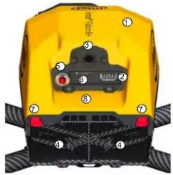 | The Central Unit consists of:(1) Carbon fiber chassis(2) USB stick slot (supports up to 16 GB, file system: FAT32, allocation unit size: 32 kilobytes) for firmware updates(3) Hole for the camera mount's carbon rod, see “Units of the Gimbal” on page 23(4) Battery compartments with retaining clips (7) for batteries(5) Power button(6) Micro SD-card slot (SD card: speed class 10 minimum, supports up to 16 GB, file system: FAT32, allocation unit size: 32 kilobytes), for flight logs (“Black Box”), must be inserted contacts upwards(7) Retaining clips for the batteries(8) Place for the label with the serial number of the UAVBuilt inside:The electronics for flight stabilization and power supplyDiversity Data Link modulesVideo Transmitter module |
Figure 2.3: Central Unit Front View without Gimbal (Camera Mount)
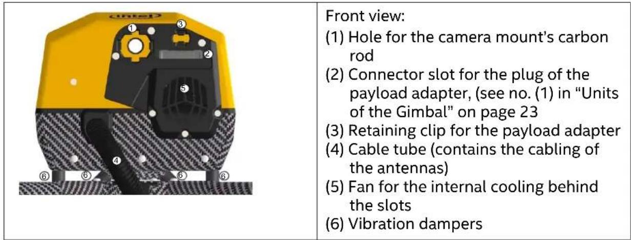
Figure 2.4: Central Unit Side View, Left Side without Gimbal (Camera Mount)

2.1.2. Motor rails of the UAV
The following figure shows the front part of the left motor rail.
Figure 2.5: Motor Rails and Equipment
| The motor rails and the related elements consist of: (1) Propellers, mounted directly on the motors (2) Brushless motors, mounted directly onto the motor mounts (3) Motor mount (4) Carbon fiber tube (5) Connector between carbon cross and motor rails (6) Landing foot (front left shown): the video link antenna (or data link antenna as applicable) is integrated (see "The Intel® Falcon™ 8+ UAV Components" on page 18). Each motor rail consists of four motor controllers seated within the carbon tube. |

CAUTION: HAZARDOUS MOVING PARTS, KEEP FINGERS AND OTHER BODY PARTS AWAY.
The motor rails are connected by a carbon cross which consists of four carbon tubes connected by a center cross piece.
The antenna cabling is found inside the tubes of the carbon cross.
2.1.3. Actively Stabilized Camera Mount (Gimbal)
The following figure describes the parts (or sub-assemblies) of the gimbal.
Figure 2.6: Units of the Gimbal
| 1 2 3 4 5 | The actively stabilized camera mount consists of: (1) Circuitry for controlling the camera (2) Payload (e. g. Sony Alpha 7R) (3) Pitch servo (4) Carbon fiber structure (5) Knurled securing nut for the actively stabilized camera mount (6) Payload adapter (see below for details). The payload adapter is the connection between the camera mount and the central unit of the UAV. It is movable when mounted on the rod of the camera mount and connected by a cable. |
| 3 4 2 | The payload adapter (backside) (1) Connector plug, should be connected to the equivalent at the front side of the UAV (see no. (2) in "Central Unit Front View without Gimbal (Camera Mount)" on page 21). (2) Adapter slot for the ball link connector of the roll servo (3) Releasing clip (4) Hole for the camera mount's carbon rod |
2.2. THE INTEL® COCKPIT CONTROLLER (CTR)
The CTR is the main control hub for the Intel® Falcon™ 8+ UAV and the attached payloads/ cameras. It is designed to be carried and operated by one person and displays all relevant flight information.
The communication between the CTR and the Intel® Falcon™ 8+ UAV is ensured by two independent 2.4 GHz digital data links. The preview video is transmitted digitally on 5.8 GHz. The CTR uses the same battery type as the Intel® Falcon™ 8+ UAV. The battery is in
the battery compartment which can be accessed from the bottom of the CTR (see "Preparing the CTR" on page 97).
The CTR serves as an interface device to the flight system. It is pre-programmed and ready to use.
The Status Display is used for communication between the CTR and the Intel ^® Falcon ^™ 8+ UAV.
The touchscreen tablet displays the live video preview from the attached camera.
Figure 2.7: Intel® Cockpit Controller (CTR) Overview
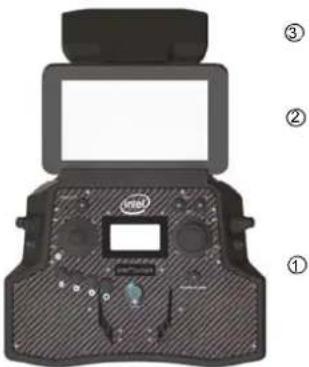 | Front view, with unfolded antenna panel. The CTR can be divided into (from bottom to top):(1) Remote control unit(2) Touchscreen tablet (for preview video and more, see “THE TOUCHSCREEN TABLET” on page 99), displayed without sun shade(3) Antenna panel (unfolded). All communication between CTR and the Intel® FalconTM 8+ UAV is sent and received by the antenna panel. It features 2.4 GHz antennas for all control and telemetry communication and 5.8 GHz antennas to receive the preview video. |
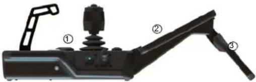 | Overview, side view right side.(1) Remote control unit(2) Touchscreen tablet, displayed without sun shade(3) Antenna panel (unfolded) |
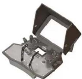 | To avoid reflections, there is a sun shield permanently attached to the touch-screen tablet. It folds away for storage and transport. |
| The functional elements of the CTR remote control unit are: (1) START/STOP button: starts/stops the motors when the left stick is simultaneously held down (see "STARTING AND STOPPING THE MOTORS" on page 127). (2) GPS button: GPS-Mode ON (3) HGT button: Height-Mode ON. When both buttons are switched ON/lit Manual-Mode is activated (4) Left rocker switch (R1) controls the camera pitch angle, right rocker switch (R2), controls different camera functions depending on the attached payload (5) Left and right control sticks (6) Status Display (see "STATUS DISPLAY" on page 166). (7) Left push button (B1) sets the camera to predefined angles +/- 90°, +/- 45° and 0° when the left rocker switch R1 (4) is pushed simultaneously, right push button (B2) controls different camera functions depending on the attached payload (8) Four function buttons for the Status Display (9) RETURN TO HOME button (10) POWER button (11) Integrated shoulder harness holders | |
| There are different connectors on the back of the CTR: • 4 X USB • 1 X H D M I The USB port labeled USB 1 can only be used to perform firmware updates from a USB stick. The other USB ports can be used to connect the Independent Camera Control (ICC) or USB sticks with pre-planned flight missions. | |
Figure 2.7: Intel® Cockpit Controller (CTR) Overview (continued)
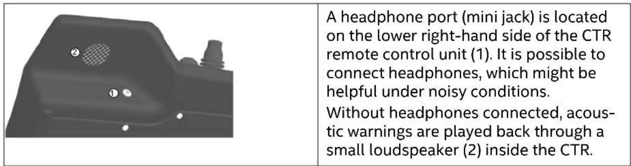

CAUTION: RISK OF PERMANENT HEARING LOSS FROM USING EARPHONES OR HEADPHONES WITH THIS PRODUCT AT HIGH VOLUME.
BEFORE PLACING HEADPHONES OR EARPHONES NEAR THE EAR, 1) FIND A QUIET ENVIRONMENT, 2) TURN THE VOLUME DOWN ON THIS PRODUCT TO THE MINIMUM SETTING, 3) CONNECT THE EARPHONE OR HEADPHONE TO THE PRODUCT, 4) PLACE THE EARPHONE OR HEADPHONE NEAR OR ON THE EAR AND 5) SLOWLY INCREASE THE VOLUME ON THE PRODUCT TO A COMFORTABLE LEVEL. AVOID INCREASING THE VOLUME ABOVE THIS LEVEL.
INCREASING THE VOLUME TO BE LOUDER THAN A NOISY ENVIRONMENT, SUCH AS A CITY STREET, MAY EXCEED SAFE LISTENING LEVELS. IF YOU EXPERIENCE DISCOMFORT OR BUZZING IN YOUR EARS, REDUCE THE VOLUME OR DISCONTINUE USE OF YOUR EARPHONES OR HEADPHONES.
RISK OF PERMANENT HEARING LOSS FROM USING THE LOUDSPEAKER IN CLOSE PROXIMITY TO THE EAR.
2.2.1. The Status Display
The Status Display shows all relevant information for flying. It is built into the CTR remote control unit. For further information about the handling of the Status Display see “STATUS DISPLAY” on page 166).
Figure 2.8: Status Display
| Via the Status Display you can view the current settings and adjust specific functions of the UAV. In order to do so, use the four buttons under the lower left corner of the Status Display. Escape (left side) is used to leave menus / sub-menus and to clear functions. In the following text, it is displayed as ESC. With the arrow LEFT button (middle, left side) and the arrow RIGHT button (middle, right side) you can scroll through menus or alter parameters. Enter (right side) is used to enter menus and activate functions. In the following text, it is displayed as ENT. |
2.2.2. The Touchscreen Tablet
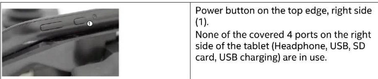
The Intel ^® based Windows ^® touchscreen tablet has an 8.3-inch screen with a resolution of 1920 X 1200 pixels. It is directly mounted on the remote control unit of the Intel ^® Cockpit Controller (CTR) and cannot be removed.
The tablet is powered by the battery of the CTR and must be switched ON before the CTR is powered ON.
The touchscreen tablet serves as a video monitor, displays flight information and gives access to extended functionality (see "THE TOUCHSCREEN TABLET" on page 99).
Figure 2.9: The Touchscreen Tablet
2.3. THE INDEPENDENT CAMERA CONTROL (ICC)
The Independent Camera Control (ICC) is an optional part of the Inspection Package (see “SOFTWARE FEATURE PACKAGES” on page 87). Thanks to the ICC, a camera operator can control the main camera functions from a gamepad, which is connected to the CTR via a USB port (USB port 2 – 4). The USB ports are in the back of the CTR in the upper left corner (see “Intel® Cockpit Controller (CTR) Overview” on page 24).
Figure 2.10: Independent Camera Control (ICC)
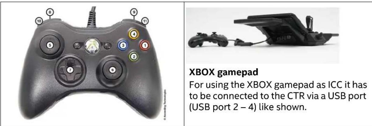
Figure 2.10: Independent Camera Control (ICC) (continued)
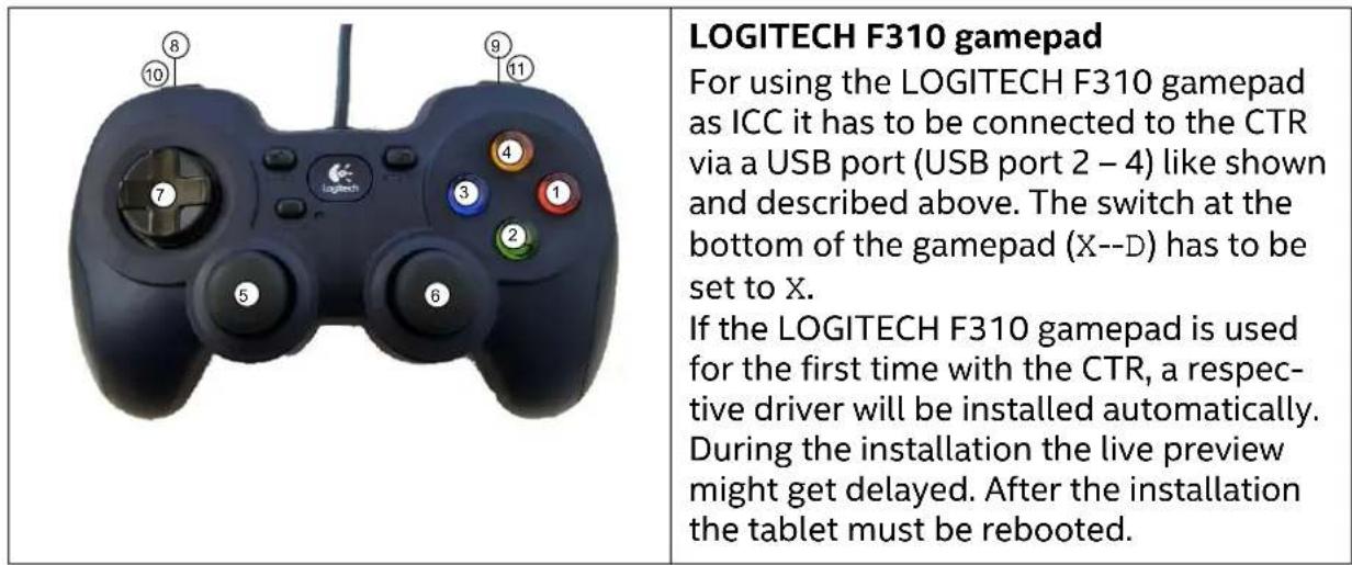
The following table presents an overview of the function assignment:
Table 2.1: Operating a Camera by ICC
| BUTTONREFERENCEDON ICC | CAMERA | |
| SONY ALPHA 7R INSPECTION-PAYLOAD | ||
| (1) Start/Stop video / | ||
| (2) Trigger photo Trigger photo (both cameras) | ||
| (3) View last image / | ||
| (4) / Change color palette (when FLIR | is active) | |
| (5) Camera tilt (up/down)Yaw (left/right) | Camera tilt (up/down)Yaw (left/right) | |
| (6) Camera tilt (up/down)Yaw (left /right) | Camera tilt (up/down)Yaw (left/right) | |
| (7) Horizontal tilt (adjust camera horizon) (left/right)Exposure compensation +/- (up/ down) | Horizontal tilt (adjust camera horizon) (left/right)Switch camera (up/down) | |
| (8) Shutter speed - Zoom + (when RGB camera is | active) | |
Table 2.1: Operating a Camera by ICC (continued)
| (9) Shutter speed | d + Zoom - (when RGB camera is active) |
| (10) Camera tilt | velocity - Camera tilt velocity - |
| (11) Camera tilt | velocity + Camera tilt velocity + |
2.4. THE 2ND OPERATOR MONITOR
The 2nd operator monitor is an optional part of the UAS and can be delivered as an additional accessory.
It can be used as a video preview monitor for the 2nd pilot, especially when used with the ICC (see “THE INDEPENDENT CAMERA CONTROL (ICC)” on page 28). There is no further (flight) information shown on this monitor.
Thanks to the 2nd monitor, a camera operator can control the video preview of the camera used. It is connected to the CTR via the HDMI port by a cable. The HDMI port is in the back of the CTR in the upper left corner (see “Intel® Cockpit Controller (CTR) Overview” on page 24).
Figure 2.11: 2nd Operator Monitor Package
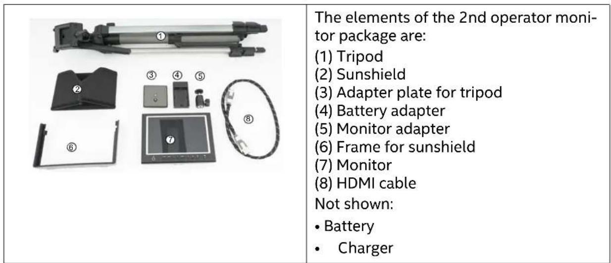
Figure 2.11: 2nd Operator Monitor Package (continued)
| The 2nd operator monitor fully assembled. |
2.5. PAYLOADS - CAMERA OPTIONS
Because of the deep integration of cameras, it is possible to change settings like aperture, shutter speed or zoom (depending on the camera) directly from the remote control unit of the Intel® Cockpit Controller (CTR) and/or the Cockpit Control application on the touchscreen tablet while the system is airborne. To ensure complete integration into the Intel® Falcon™ 8+ UAV, every payload must undergo mechanical and electrical modifications. Therefore, only payloads approved by Intel are allowed. Payloads which have not been integrated might affect the compass calibration due to magnetic emissions by the camera and could have detrimental effects on the flight performance. If you require assistance with determining which payload to choose for your application, please contact our support team: support@intel.com.
Figure 2.12: Camera Control via the Intel® Cockpit Controller (CTR)
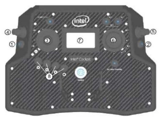
All cameras integrated on the Intel ^® Falcon ^™ 8+ UAV can be controlled via the CTR. Several switches on the CTR are assigned to camera controls.
(1) Push Button B1: sets the camera to predefined angles +/- 90°, +/- 45° and 0° when R1 (4) is pushed simultaneously (see below for details)
(2) Push Button B2: changes the function depending on the connected payload
(3) Push Button B3: trigger button on top of the left control stick (S1)
(4) Rocker Switch R1: camera tilt
(5) Rocker Switch R2: changes its function depending on the camera used
(6) Control Stick S2: turning the right control stick (S2) controls the yaw axis of the UAV.
(7) Status Display and related control buttons
(8) ESC, LEFT, RIGHT, ENT: depending on the payload, additional options can be accessed via the Status Display. Pushing ENT and selecting Camera Options opens the respective menu (see "Status Display" on page 27 and see "STATUS DISPLAY" on page 166).
For exact details regarding accessible functions see the individual payload descriptions.
Figure 2.12: Camera Control via the Intel® Cockpit Controller (CTR) (continued)
Setting the Camera Angle
The Main Screen of the Status Display shows the camera angle. 0^ means the camera is looking straight forward and is leveled horizontally. -90^ means the camera is looking down, 90^ means it is looking up.
Push the Rocker Switch R1 away from you to tilt the camera downwards. Pull the Rocker Switch R1 towards you to tilt the camera upwards. The further R1 is pulled or pushed the quicker the tilt movement.
When the camera is not at 0^ , a single push of button B1 will set it back to 0^ . When the camera is at 0^ , pushing and holding B1 and simultaneously pushing R1 shortly, will set the camera to -45^ , another short push of R1 while holding B1 will set it to -90^ . When pulling R1 while holding B1 the camera can be tilted upwards accordingly in 45^ increments.
2.5.1. Changing a Payload (Camera)
Cameras are designed to remain within their gimbal (camera mount). The complete gimbal with camera can be exchanged without tools. The Intel® Falcon™ 8+ UAV automatically identifies the attached camera and the menus of the Status Display on the CTR are changed accordingly.
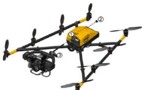
Figure 2.13: Installing the Camera Mount
natural_image
Yellow and black quadcopter drone with camera module (no visible text or symbols)To install the camera mount:
-
Feed the camera mount carbon rod into the front side of the central unit (1). The Thumbscrew (2) is not attached at this time. Make sure the carbon rod is not at an angle when it is inserted.
-
Fix the payload adapter (3). Take care that the connector plug of the adapter fits to the equivalent at the front side of the UAV. See detail #1 below.
-
On the roll servo, make sure the ball link connector ball is fixed in the respective slot in the adapter when you fix the camera mount onto the UAV. See detail # 2 below.
-
Press the releasing clip of the payload adapter into the respective counterpart opening at the front side of the UAV. See detail # 3 below.
-
Install the thumbscrew nut (2) on the back side of the central unit (Finger tight. See detail # 4 below.
Figure 2.13: Installing the Camera Mount (continued)
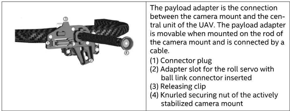
Figure 2.14: Removing the Camera Mount
| To remove the camera mount: 1. Remove the knurled securing nut (1) of the camera mount at the back side of the central unit. | |
| 2. Carefully disconnect the payload adapter with pressure against the release clip of the adapter (2). 3. Disconnect the ball of the ball link connector of the roll servo out of the adapter slot. 4. Pull out the camera mount gently. Make sure it comes out straight (not at an angle) |
2.5.2. Payload and compass calibration

CAUTION: WHEN INSTALLING A NEW PAYLOAD ONTO AN INTEL® FALCON™ 8+ UAV, IT IS NECESSARY TO PERFORM A PAYLOAD CALIBRATION AND A COMPASS CALIBRATION (STRICTLY IN THAT ORDER).
THE INTEL® FALCON™ 8+ UAV WILL SAVE THE CALIBRATIONS FOR THAT EXACT PAYLOAD AND REMEMBER IT THE NEXT TIME THE PAYLOAD IS USED.
IF YOU FAIL TO CALIBRATE, THE SYSTEM WILL USE DEFAULT PARAMETERS WHICH WILL LEAD TO DECREASED HEADING ACCURACIES.
TO PERFORM THE CALIBRATIONS, PLEASE FOLLOW THE STEPS BELOW.
The payload calibration is stored in the payload itself, and the compass calibration is stored in the UAV.
2.5.2.1. Payload calibration
The payload calibration can be done indoors with the motors switched off.
- Attach the payload you are performing the calibration on.
- Switch the payload ON, then the Intel ^® Falcon ^™ 8+ UAV, then the touchscreen tablet and the finally the CTR.
- On the CTR push the ENT button of the Status Display and navigate to Settings > Payload calib (see "STATUS DISPLAY" on page 166).
- Make sure the camera can turn freely from the full down position to the full up position (with the Inspection Payload, you will need to raise the Intel® Falcon™ 8+ UAV to make sure the payload does not hit the ground and cause damage when it tilts downwards).
- Push ENT to start the calibration. The camera will first rotate fully downwards and then progressively move to the fully upwards position. Do not touch the Intel ^® Falcon ^™ 8+ UAV during the process.
-
When the payload does not move anymore, switch off the payload, then the Intel® Falcon™ 8+ UAV, then the touchscreen tablet and finally, the CTR.
-
Restart the system in the specific sequence (see step #2 above).

CAUTION: IT IS IMPORTANT TO RESTART THE SYSTEM IMMEDIATELY AFTER EACH CALIBRATION. THE NEW CALIBRATION PARAMETERS WILL ONLY BECOME ACTIVE AFTER RESTARTING THE SYSTEM.
- Repeat the above steps for each new payload to be used with the Intel ^® Falcon ^™ 8+ UAV. Once a payload has been calibrated, the Intel ^® Falcon ^™ 8+ UAV will recall the settings.
2.5.2.2. Compass calibration
The compass calibration needs to be done outdoor in flight.
- Attach the payload you are performing the calibration on.
- Take the Intel ^® Falcon ^™ 8+ UAV out to a spot with good GPS reception and no magnetic disturbances.
- Switch the payload ON, then the Intel ^® Falcon ^™ 8+ UAV, then the touchscreen tablet, and finally, the CTR; take off.
- Have the Intel ^® Falcon ^™ 8+ UAV hover in GPS-Mode at about 30 m above ground level where no magnetic disturbances are to be expected.
- On the CTR push the ENT button of the Status Display to navigate to Settings > Compass Calib (see "STATUS DISPLAY" on page 166).
- Push ENT to confirm. The Intel® Falcon™ 8+ UAV will make a 400° turn.
- Once the Intel ^® Falcon ^™ 8+ UAV has finished the turn, land, switch off the camera, then the Intel ^® Falcon ^™ 8+ UAV, then the touchscreen tablet, and finally, the CTR. Restart the complete system in the specific sequence (see step #2 above).

CAUTION: IT IS IMPORTANT TO LAND AND RESTART THE SYSTEM IMMEDIATELY AFTER EACH CALIBRATION PROCESS. THE NEW CALIBRATION PARAMETERS WILL ONLY BECOME ACTIVE AFTER RESTARTING THE SYSTEM.
- Repeat the above steps for each new payload to be used with the Intel ^® Falcon ^™ 8+ UAV. Once a payload has been calibrated, the Intel ^® Falcon ^™ 8+ UAV will recall the settings.
2.5.2.3. Adjusting the camera horizon
The zero position of the camera horizon and/or tilt angle might occasionally need adjustment, as it might change due to temperature variations. The adjustment of the camera horizon can be done indoors with the motors switched off.
To re-adjust the zero position, follow these steps:
- Switch the Intel ^® Falcon ^™ 8+ UAV and the CTR ON as usual.
- Select the Link Loss Procedure.
- Push the left control stick of the CTR fully upwards and hold it.
- While holding the left control stick fully upwards, use the right control stick to adjust the camera. It now directly controls the camera angles.
- When the position is set correctly, release both control sticks. This position will automatically be saved as the new zero position.
It is also possible to adjust the camera horizon in flight, but not the tilt angle. To adjust the horizon in flight:
- Enter the menu of the Status Display by pushing ENT.
- Navigate to Camera Options > Adjust Horizon.
- Push ENT.
- Use the arrow LEFT/RIGHT keys of the Status Display to change the horizon.
- Push ENT to confirm.
2.5.3. Sony Alpha 7R Full Frame Camera
The Sony Alpha 7R has two main function dials that can be controlled through the CTR (see "Camera Control By The CTR" on page 40).
Figure 2.15: Sony Alpha 7R and SD Card Slot
| Specifications: • Sensor size: 35.90 mm x 24.00 mm • Resolution: 36.4 Mpx (7360 x 4912 pixels) • Lens: Sonnar® T* FE 35 mm F2.8 ZA (SEL35F28Z) • Weight incl. lens and gimbal: ~ 790 g. • Approximate max. flight time: 16 min • Suggested applications: Aerial photo- graphy, inspection and surveying Approved lenses: • Sonnar® T* FE 35 mm F2.8 ZA (SEL35F28Z) Please note that all other available full frame lenses are too heavy and cannot be approved | |
| Images are stored on an SD card, which is inserted underneath a lid on the right back side of the camera. To transfer images to the computer, please use an SD card reader which is connected to the computer. For further information: https://esupport.sony.com/US/p/model-home.pl?mdl=ILCE7R&LOC=3#/manualsTab |
2.5.3.1. General Care
- Always handle the gimbal with care. If you need to tilt the camera manually (when not connected or while the Intel® Falcon™ 8+ UAV is switched off), please do so very cautiously. If too much force is applied, the gear wheels of the servo motors might break.
- The camera is powered by the Intel® Falcon™ 8+ UAV battery to save weight. When you switch off the system, switch off the camera first and wait for 10 seconds to allow the camera to fully power down and store all images and settings. Only then should you switch off the Intel® Falcon™ 8+ UAV. If you switch off the Intel® Falcon™ 8+ UAV too early, you will cut the power supply of the camera and risk losing data.
- Keep the airplane mode of the camera switched on, to avoid radio interference from the camera (MENU > 📋 Airplane Mode > ON).
2.5.3.2. Camera Control By The CTR
This section describes how the Sony Alpha 7R can be operated by using the functional elements of the CTR.
Figure 2.16: Sony Alpha 7R CTR Control Layout
| 4 ① ② ③ ④ ⑤ ⑥ ⑦ ⑧ ⑨ ⑩ ⑪ ⑫ ⑬ ⑭ ⑮ ⑯ ⑰ ⑱ ⑲ ⑳ ㉑ ㉒ ㉓ ㉔ ㉕ ㉖ ㉗ ㉘ ㉙ ㉚ ㉛ ㉜ ㉝ ㉞ ㉟ ㉳ ㉟ ㉳ ㉟ ㉟ ㉟ ㉟ ㉟ ㉟ ㉟ ㉟ ㉟ ㉟ ㉟ ㉟ ㉟ ㉟ ㉟ ㉟ ㉟ ㉟ ㉟ ㉟ ㉟ ㉟ ㉟ ㉟ ㉟ ㉟ ㉟ ㉟ ㉟ ㉟ ㉟ ㉟ ㉟ ㉟, (see "Setting the Camera Angle" on page 33 for details). Push Button B2 (2): changes the function depending on the connected payload. Push Button B3 (3): trigger button Rocker Switch R1 (4): camera tilt, changes the angle smoothly. Rocker Switch R2 (5): camera tilt; Dial 1 or Dial 2, depending on B2 Control Stick S2 (6): turning the right control stick (S2) controls the yaw axis of the UAV. Status Display (7): see "Camera Options By The Status Display" on page 41 ESC, LEFT, RIGHT, ENT (8): Status Dis-play control buttons (see "Status Dis-play" on page 27). | |
| /35 | The Sony Alpha 7R has two main func- tion dials that can be controlled by the CTR. The function of Dial 1 on the Sony A7R can be controlled by R2, when B2 is in position 1 (LED off). The function of Dial 2 can be controlled by R2, when B2 is in position 2 (LED on/blue) or via the Status Display by pushing ENT > Camera Options > Dial 2. The default functions of Dial 1 and 2 depend on the selected shooting mode on the camera. The table below shows the dependencies. |
© 2018 Intel Corporation. All rights reserved 40
2.5.3.3. Camera Options By The Status Display
Table 2.2: Sony Alpha 7R Camera Control By Camera Functions
| B2 POSITION | R2 FUNCTION | CAMERA SET TO S MODE (SHUTTER PRIORITY) | CAMERA SET TO A MODE (APERTURE PRIORITY) | CAMERA SET TO M MODE (MANUAL) |
| 1 (LED off) Dial | 1 Shutter speed | Aperture Aperture | ||
| 2 (LED on/ blue) | Dial 2 Exposure | compensation | Exposure compensation | Shutter speed |
Push the ENT button of the Status Display to enter the menu. Navigate to Camera Options. The following options are available for the Sony Alpha 7R.
Table 2.3: Sony Alpha 7R Camera Control By Status Display
| THE FOLLOWING OPTIONS ARE AVAILABLE FOR THE SONY ALPHA 7R. | |
| Record/Stop | Starts and stops a video recording |
| Dial 2 | See previous table for details. |
| Review | Reviews images already stored on the SD card of the camera.UseRocker Switch R2(no. 5 in figure above) to navigate. |
| Adjust Horizon | Occasionally the neutral position of the Gimbal's Servo Motors might need to be re-adjusted. Use this command to adjust the horizon (roll angle) while flying. If the system is still on the ground and the motors are not running this can also be done in both axes (roll and tilt) with the control sticks. see “Adjusting the camera horizon” on page 37. |
| Roll Comp.On/Off | Default = ON.When Roll Comp. = Off the gimbal will no longer compensate roll movements of the Intel® FalconTM 8+ UAV.This can be useful when doing dynamic video flights. |
2.5.3.4. Camera Settings
The following section describes the most important settings of the camera when used with the Intel ^® Falcon ^™ 8+ UAV.
Figure 2.17: Camera Settings By Camera Sony Alpha 7R
| The most important settings can be quickly accessed via the buttons: (1) Fn: see below (2) MENU: see below (3) C2: provides quick access to the Focus Mode (4) WB: provides quick access to White Balance. ISO can be quickly accessed by turning the control wheel in the back of the camera. | |
| After pushing the Fn button (number (1) above) by default the following parameters can be accessed: Top row: Drive Mode / Flash Mode / Flash Comp. / Focus Mode / Focus Area / Exposure Comp. Bottom row: ISO / Metering Mode / White Balance / DRO/Auto HDR / Creative Style / Shoot Mode | |
| The camera menu can be accessed by pushing the MENU button (number (2) above). On the first page of the menu, the Image Size and Quality can be set. Refer to the camera manual for further details. |
2.5.4. Inspection Payload
The Inspection Payload consists of two cameras: Panasonic RGB camera and infrared (IR) camera FLIR TAU 2 640.
Figure 2.18: Inspection Payload
| Specifications of the Panasonic RGB camera: • Sensor size: CMOS Sensor 1/2.3", 6.2 x 4.6 mm • Resolution: 12.1 Mpx (4000 x 3000 pixel) • Lens: LEICA DC VARIO-ELMAR F3,3 - 6,4 / Multistage Iris Diaphragma (F3,3 - 8,0 (W), F6,4 - 8,0 (T)) • Focal length: 4.3 - 129 mm (24 - 720 mm, 35 mm equiv.) • Optical zoom: 30x • Weight incl. lens and gimbal: ~ 550 g. • Approximate max. flight time: 18 min • Suggested applications: Inspection Depending on the model of Panasonic camera, you will find further information here: TZ71: https://www.panasonicstore.ie/wp-content/uploads/2015/05/DMCTZ70.pdf ZS50: ftp://ftp.panasonic.com/camera/om/dmc-zs50_adv_om.pdf Please note that the WiFi functionality of these cameras is disabled for the use with the Intel® Falcon™ 8+ UAV. Specifications of the IR camera FLIR Tau 2 640: • Thermal Imager: Uncooled VOx Microbolometer • Resolution: 640 × 512 pixel • Pixel pitch: 17 μm • Spectral band: 7.5 - 13.5 μm • Focal length: 19 mm (~ 59 mm, 35 mm eqiv.) Further details: http://www.flir.com/cores/dis-play/?id=54717 |
Figure 2.18: Inspection Payload (continued)
| The Panasonic camera needs its own fully charged battery to work. The battery slot can be accessed from the bottom of the payload. The SD card of the camera is inserted next to the battery. A separate charger for the Panasonic batteries is supplied with the payload. | |
| The FLIR Tau 2 640 camera is powered by the Intel® Falcon™ 8+ UAV battery to save weight, and does not need to be switched ON or OFF. The micro SD card of the FLIR Tau is inserted at the side of the camera, with the contacts of the micro SD facing towards the camera lens. Each time the Intel® Falcon™ 8+ UAV is switched on, a new, subsequently numbered sub-folder (FLIR0000, FLIR0001, FLIR0002...) is created on the micro SD card. Up to 128 image files are stored in one folder. If more than 128 images are taken during one flight, a new sub-folder will be created where the additional images are stored. Before the camera can be used, the black cap must be removed from the lens. The images are stored in a proprietary file format .ARA. The 14-bit RAW output from the camera is captured, which allows the displayed temperature range to be set during post processing. Using Thermal Editor (part of AscTec Navigator), the RAW images can be displayed and converted into a FLIR Tools-compatible Radiometric JPEG file. AscTec Navigator Software can be downloaded from the download area: http://intel.com/FalconDownloads. A detailed manual of the software is available here: http://intel.com/FalconManual. | |
| [IMAGE] | When an Inspection Payload is attached, the number 999 will appear underneath the flight mode icon of the menu on the Status Display. This number signifies the number of images which can be stored onto the Micro SD card of the FLIR Tau 2 640. The maximum number that can be displayed on the screen is 999, however, the actual number of images the SD card can store is higher than 999. Therefore, the displayed number will not count down until the SD Card has a capacity of less then 999 images. |
| [IMAGE] | When the FLIR Tau 2 640 IR Raw Data Logger cannot access the SD card, an error message ERR will be displayed instead of the number of remaining images.In case this happens, please take out the SD card and troubleshoot.If after reinserting, if the error message remains, reformat the SD card.Format settings are:File system: FAT32Allocation unit size: 64 kilobytesVolume label: FLIRSD |
The FLIR and the Panasonic RGB camera can record video. During video recording on the Panasonic RGB camera, the camera will not output any preview video. This means that the preview video on the touchscreen tablet of the CTR must be switched to show the FLIR image (see "Inspection Payload Control By The CTR" on page 46).
2.5.4.1. General Care
- Always handle the gimbal with care. If you need to tilt the camera manually (when not connected or while the Intel® Falcon™ 8+ UAV is switched off), please do so very cautiously. If too much force is applied, the gear wheels of the servo motors might break.
- Keep the airplane mode of the camera switched on, to avoid radio interference from the camera (MENU > Setup > Page 2 > Airplane Mode > ON).
2.5.4.2. Inspection Payload Control By The CTR
The following figure describes in detail how the Inspection Payload can be controlled by the functional elements of the CTR.
Figure 2.19: Inspection Payload: CTR Control Layout
| FLIR Tau 2 640 performs flat field correction (FFC). The FLIR automatically performs a FCC every 10 seconds (for more information about the FFC please read: http://www.flir.com/cvs/cores/knowledgebase/index.cfm?CFTREEITEM-KEY=327&view=35774 | |
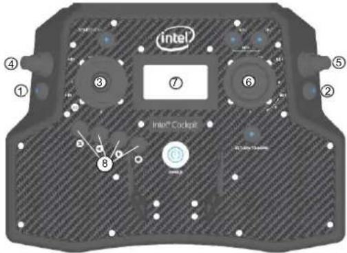 | Push Button B1 (1): sets the camera to predefined angles +/-90°, +/-45° and 0° when R1 (4) is pushed simultaneously (see “Setting the Camera Angle” on page 33 for details).Push Button B2 (2): switches between the cameras for live preview (FLIR and Panasonic).Push Button B3 (3): Trigger button. Both cameras will be triggered simultaneously, regardless of which camera is selected for the live preview.Rocker Switch R1 (4): camera tilt, changes the angle smoothly.Rocker Switch R2 (5): Changes its function depending which camera is selected for live preview. See the table below for details.Control Stick S2 (6): turning the right control stick (S2) controls the yaw axis of the UAV.Status Display (7): see “Inspection Payload Control By The Status Display” on page 47.ESC, LEFT, RIGHT, ENT (8): Status Display control buttons. (see “Status Display” on page 27). The table below shows the available parameters depending on the shooting mode of the camera. |
Table 2.4: Inspection Payload: CTR Control Layout
| B2 POSITION | ACTIVATED CAMERA | R2 FUNCTION | |
| 1 (LED off) | Panasonic camera | Zoom in/out Parameters like shutter speed, aperture and ISO need to be set directly on the camera before take-off. | |
| 2 (LED on/red) | FLIR Up - Trigger | flat field correctionDown - Cycle through color palette | Parameters like isotherms and AGC (Automatic Gain Control) need to be set via configuration file on the FLIR SD card before take-off. |
2.5.4.3. Inspection Payload Control By The Status Display
Push the ENT button of the Status Display to enter the menu. Navigate to Camera Options. The following options are available for the Inspection Payload:
Table 2.5: Inspection Payload Control By Status Display
| THE FOLLOWING OPTIONS ARE AVAILABLE FOR THE INSPECTION PAYLOAD: | |
| Switch Camera | Switches the live image preview on the touchscreen between the FLIR Tau 2 640 and the Panasonic Lumix camera. |
| Adjust Horizon | Occasionally the neutral position of the gimbal's servo motors might need to be re-adjusted. Use this command to adjust the horizon (roll angle) while flying. If the system is still on the ground and the motors are not running this can also be done in both axes (roll and tilt) with the control sticks, see “Adjusting the camera horizon” on page 37. |
| Roll Comp.On/Off | Default = ON. When Roll Comp. = Off, the gimbal will no longer compensate roll movements of the Intel® FalconTM 8+ UAV. This can be useful when doing dynamic video flights. |
Notes Shooting parameters need to be set directly on the camera before take-off.
Additional cameras may be available. Please check http://intel.com/FalconManual for an updated version of the manual.
2.5.5. Intel® High Resolution Imaging Payload
The Intel® High Resolution Imaging Payload consists of a Sony RX1R II camera with a Topcon B111 GNSS receiver. When the Intel High Resolution Imaging Payload is connected, the external Topcon receiver is used as a redundancy backup receiver for the internal GPS receiver and for geo-referencing the images during post-processing. The internal GPS receiver has precedence over the Topcon receiver and is used for positioning the UAV in-flight. If for any reason the internal GPS receiver fails the external Topcon receiver takes over.
Notes
The use of the Intel Imaging Payload requires Intel Falcon 8+ UAS firmware version package 1.2 or higher (see "Firmware update" on page 61).
Figure 2.20: Intel® High Resolution Imaging Payload specifications
| ① | Specifications of the Sony RX1R II camera: • Sensor size: 35.90 mm x 24.00 mm • Resolution: 42.4 Mpx (7952 x 5304 pixels) • Lens: ZEISS Sonnar T 35mm F2.0 single focus lens (fixed) • Weight incl. lens and gimbal: ~ 796 g • Approximate maximum flight time: 16 min • Suggested applications: Aerial photography, inspection and surveying. The antenna of the Topcon B111 GNSS receiver (1) is located at the left side of the payload (front view). |
| Images are stored on the SD card, which is inserted underneath the lid on the bottom right back side of the camera (1). To transfer images to a computer, please use an SD card reader which is connected to the computer. For further information please visit: https://esupport.sony.com/US/p/model-home.pl?mdl=DSCRX1RM2&LOC=3#/manualsTab |
2.5.5.1. General care
- Always handle the gimbal with care. If you need to tilt the camera manually (when not connected or while the Intel Falcon 8+ UAV is switched off), please only do so very cautiously. If too much force is applied, the gear wheels of the servo motors may break.
- Do not lift the payload by the antenna of the Topcon B111 GNSS receiver. This will permanently damage the connection between the antenna and the camera mount.
- The camera is powered by the Intel Falcon 8+ UAV battery to save weight. When you switch the system OFF, always switch the camera OFF first, and wait for 10 seconds to enable the camera to fully power down and store all images and settings. After doing so, switch OFF the Intel Falcon 8+ UAV. If you switch the Intel Falcon 8+ UAV OFF too early, you will cut the power supply to the camera and risk losing data.
- Please keep the airplane mode of the camera switched ON in order to avoid radio interference from the camera (MENU > Wireless > Airplane Mode > ON).
2.5.5.2. Camera control by the CTR
This section describes how the Sony RX1R II can be operated by using the functional elements of the Intel Cockpit Controller (CTR).
Figure 2.21: Sony RX1R II CTR control layout
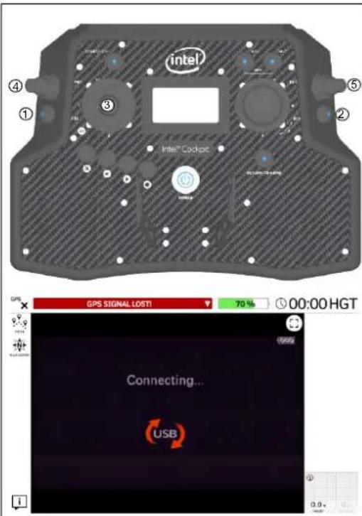
Push Button B1 (1): sets the camera to pre-defined angles +/-90°, +/-45° and 0° when
Rocker Switch R1 (4) is pushed simultaneously (see "Setting the Camera Angle" on page 33 for details).
Push Button B2 (2): activates the camera settings mode (the viewfinder image on the touchscreen tablet turns black and the screen will display Connecting... USB, like shown to the left).
Pushing B2 while in the camera settings mode scrolls through the available adjustable settings (ISO, shutter speed, exposure compensation).
Rocker Switch R2 (5): by moving this switch up/down, the value of the setting selected with B2 can be adjusted up or down.
Please note that the adjustable settings depend on the selected exposure mode of the camera, P(rogram), A(perture), S(hutter), M(anual) which is selected on the camera. If no button is pressed within 10 seconds the camera changes back to the picture capture mode and the viewfinder image becomes visible again.
Push Button B3 (3): trigger button, when in picture capture mode, it triggers the camera. Pressing the trigger button while in the camera settings mode brings you back to the picture capture mode.
Rocker Switch R1 (4): camera tilt, changes the angle smoothly.
2.5.5.3. Camera settings
The following section describes the most important functions of the camera when used with the Intel Falcon 8+ UAV.
Figure 2.22: Camera settings for Sony RX1R II
| The most important functions can be quickly accessed via the buttons: (1) Custom button (labeled C1 on the camera): provides quick access to ISO value settings. (2) Control dial (3) Control Wheel: the wheel acts also as a 4-way keypad. When the upper part of the wheel is pressed, it circles through various display modes. (4) Power switch (5) Exposure mode dial: P(rogram), A(perture), S(hutter), M(anual) (6) Fn button (7) MENU button (8) Exposure compensation dial (9) Shutter button. Capabilities such as aperture, shutter speed etc. can be quickly accessed by turning the control wheel (2) in the back of the camera (function of this wheel depends on the operating mode used). | |
| After pushing the Fn button (number (6) above) by default the following parameters can be accessed: Top row: Drive Mode / Flash Mode / Flash Comp. / Focus Area / Exposure Comp. / ISO Bottom row: Metering Mode / White Balance / DRO / Auto HDR / Creative Style / LPF effect / Shoot mode The camera menu can be accessed by pushing the MENU button (number (7) above). On the first page of the menu, the important parameters such as Image Size and Quality can be set. Please refer to the camera manual for further details. |
2.5.5.4. Geo-reference
It is possible to geo-reference all images taken when the UAS had a valid GNSS signal during the flight. Every time an image is triggered, the positional information is written into the log file of the Intel Falcon 8+ UAV. During post-processing this information can be extracted and combined with the images. Please see chapter "INTEL® FALCON™ 8+ UAV FLIGHT LOGS" on page 91 for further details.
Notes
If the Intel® High Resolution Imaging Payload does not receive a sufficient GPS signal, "Payl. GPS not ready" is shown in the bottom line of the Status Display of the CTR. As long as this message is shown no geo-references can be stored in the above mentioned log file.
Possible workaround:
- Wait several minutes. It might take some time until the GPS receiver of the payload has synchronized.
- Move to a location with better GPS reception.
- Power the UAV OFF and then ON again.
If the message disappears the GPS signal is strong enough.
For proper operation of the payload, please make sure the Intel Falcon 8+ UAV and the payload is updated to the latest available version. Download the Intel Falcon 8+ UAV firmware from http://intel.com/FalconDownloads and install it as described in "Intel® Falcon™ 8+ UAS firmware updates" on page 193.
The payload also contains updateable firmware. Check the currently installed firmware version of the payload by tapping on the "i" INFO button in the lower left corner on the touchscreen tablet.
The following section describes the payload firmware update process:
Figure 2.23: Payload Firmware Update
natural_image
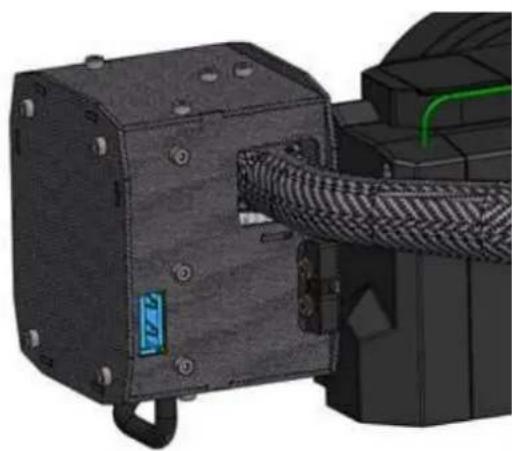
3D mechanical assembly showing a black housing connected to a coiled cable with green pipe routing (no visible text or symbols)For the payload firmware update process the respective payload has to be mounted and connected to the Intel Falcon 8+ UAV.
-
Download the latest payload firmware from http://intel.com/FalconDownloads and save this file (FW.BIN) onto a USB stick.
-
Insert the USB stick containing the license file (FW.BIN) into the USB port on the payload (see picture to the left).
-
With the USB stick in the payload USB port, power ON the Intel Falcon 8+ UAV. The update process will start automatically.
-
Wait 3 minutes for the process to finish. After that the Falcon 8+ UAV can be powered OFF.
-
Remove the USB stick and check if the license file (FW.BIN) has been renamed. After a successful update, the license file name is renamed to _FW.BIN (an underscore has been added to the filename as prefix). The payload is now ready to be used.
2.5.6. Intel® Imaging Payload
The Intel® Imaging Payload consists of a Sony R10C RGB camera and an internal compute module board. Additionally the payload is equipped with Intel® RealSense™ technology, which allows the Intel Falcon 8+ UAV to detect and avoid obstacles in its flight path.
There are two Intel RealSense modules on the payload, one looking towards the front and another looking 90 degrees to the left. Together these cameras enable an approximate 180 degree view side to side.
The onboard compute board controls the cameras of the Intel RealSense modules, stores the payload images and creates an obstacle map of the surroundings which enables the Obstacle Avoidance feature.
Obstacle Avoidance (OA) helps the pilot to keep the UAV in a standoff distance from the object that he/she wants to inspect. OA also registers any obstacles in the immediate vicinity and helps the pilot avoid these while focusing on the inspection.
Notes
The use of the Intel Imaging Payload requires Intel Falcon 8+ UAS firmware version package 1.2 or higher (see "Firmware update" on page 61).
Information about how to use the OA feature can be found in section "Obstacle Avoidance (OA)" on page 65.
Figure 2.24: Intel® Imaging Payload Specifications
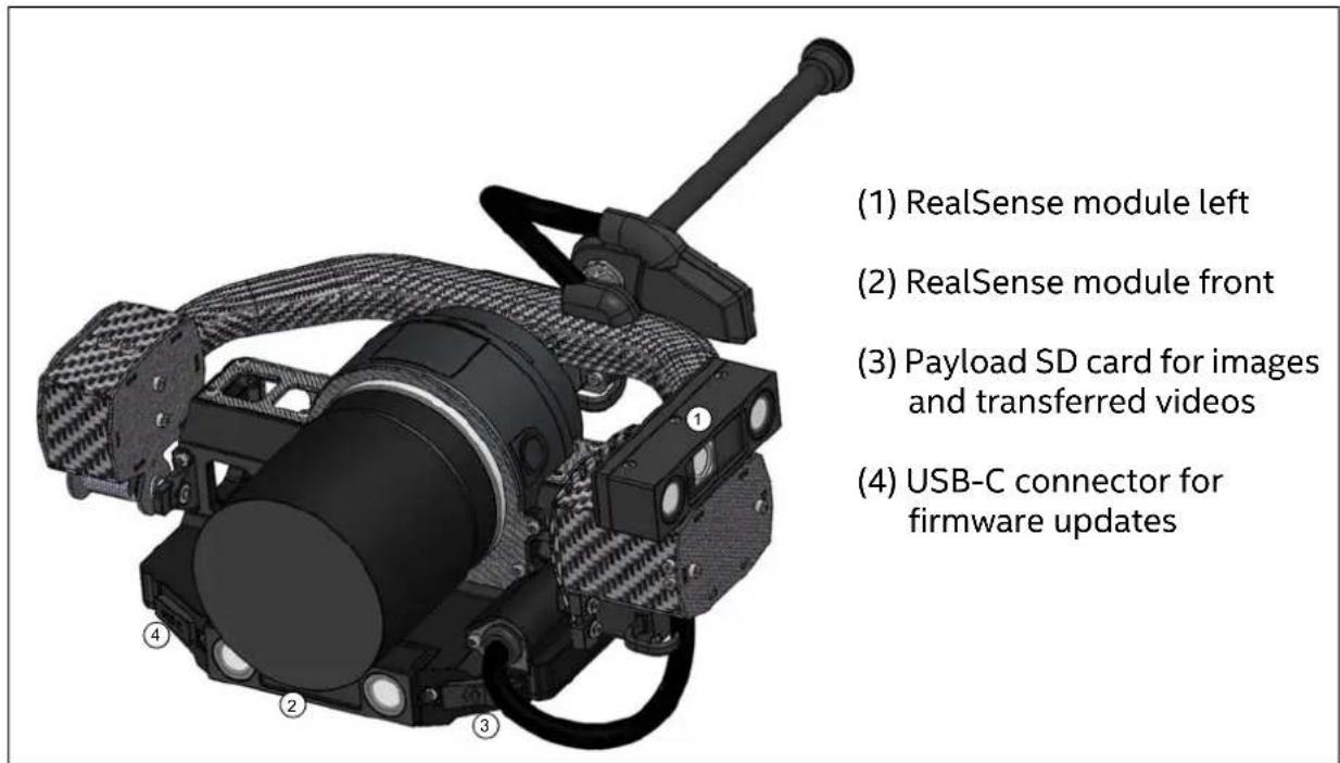
Figure 2.24: Intel® Imaging Payload Specifications (continued)
| Specifications of the Sony R10C 20MP camera:Sensor size: CMOS Sensor APS-C size, 23.2 x 15.4 mmResolution: 20.1 Mpx (5456 x 3632 pixels)Lens: Sony Sonnar® T* E 24 mm F1.8 ZA (changeable)Focal length: 24 mmImage formats: JPEG, Sony ARWVideo formats: 1920 x 1080 @ 30 fps, MP4 (videos are stored on the camera SD card)Weight incl. lens and gimbal: ~ 750 g (with 24 mm f/1.8 lens).Approximate maximum flight time: 16 minSuggested applications: Inspection and survey | Approved lenses:Sony Sonnar® T* E 24 mm F1.8 ZA (SEL24F18Z) - 225g. For survey missions requiring maximum image quality (default lens)Sony E PZ 16-50 mm F3.5-5.6 OSS (SELP1650) - 116g. For inspection tasks, zoom capability and optical stabilizer assist in live inspection tasksSony Sonnar T* FE 35 mm F2.8 ZA (SEL35F28Z) - 120 g. For fixed distance inspection or building survey tasksSony E 20 mm F2.8 (SEL20F28) - 69 g. Very lightweight all-around lens, suitable for survey missions with demand for large area coveragePlease note that other lenses, while physically compatible with the camera, may be too heavy and are not approved. |
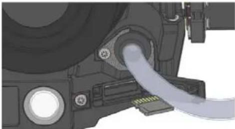 | Images are stored on the payload SD card, which is inserted in the front left hand corner as shown to the left.Recorded videos can be transferred to this payload SD card as well (see below).To transfer files from the payload card to a computer, please use an SD card reader connected to the computer. |
| Note: The frequency with which images can be captured depends on how quickly the image data can be written to the target media during a flight. During flights images are written directly to the user-changeable payload microSDHC card for easy access to the files post-flight.The microSDHC bus type and speed class, along with the card manufacturer's real-world performance specifications, set the limit for how frequently images can be saved to the media during flights. Using the supplied microSDHC card, Intel has successfully validated repeated contiguous image captures of up to 500 images with a frequency of up to 1 image capture every 1.5 seconds. Please note that when using microSDXC cards in the payload, they will work in SDHC compatibility mode and the stated read/write speed performance may not be achievable. | |
Figure 2.24: Intel® Imaging Payload Specifications (continued)
natural_image
Mechanical assembly diagram showing two views of a device with a blue arrow pointing to a component (no text or symbols present)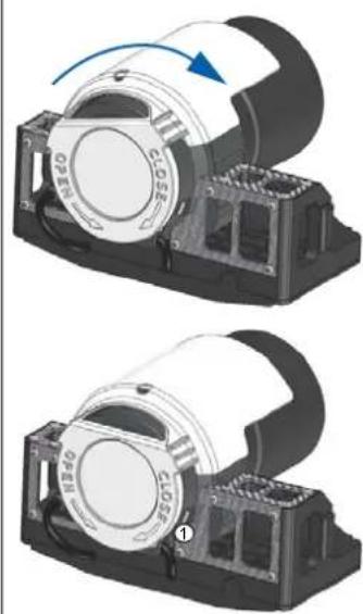
natural_image
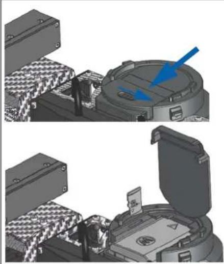
Two views of a mechanical device with a blue arrow indicating rotation, showing internal components (no text or symbols)Videos are stored on the camera SD card, which is inserted in the back of the camera underneath the battery lid. By default, video files recorded during a mission can automatically (after a confirmation, see figure "Confirmation of video file transfer" on page 58) be transferred to the payload SD card. If access to the camera SD card is necessary:
- Open the lid by pushing and holding the OPEN slider to the right, while simultaneously pushing the lid in the direction indicated by the arrow.
- Remove the micro SD card from the slot by lightly pressing it inwards, after which the card pops out for easy removal.
If using the payload in hot environments with direct exposure to sunlight, please attach the supplied camera sun cover onto the camera before the flight (see pictures to the left). The cover reflects sunlight and allows the camera to operate reliably. To attach the cover:
- Mount the cover onto the camera
- Tilt it slightly to the left.
- Turn the cover in the direction of the CLOSE arrow, to lock the cover in place.
To remove the cover:
- Keep the release latch (1) pressed while turning the cover in the direction of the OPEN arrow and lift it up.
File structure of image files
Photo images are stored on the payload SD card with the following described conventions.
Every time, the Intel Falcon 8+ UAV is switched on, a new image directory with a consecutive number will be created on the payload SD card.
If a GPS signal was available, the date and time in the directory name is taken from the GPS signal.
- 000001_201802191200 = directory name with a consecutive mission number (000001), date (YYYY/MM/DD) and time (hh/mm)
• R10C001234.JPG = R10C image with consecutive number (001234)
• R10C001235.JPG = R10C image number (001235)
• R10C001236.JPG = R10C image number (001236)
• Etc.
- 000002_201802191223 = directory name with a consecutive mission number (000002), date (_YYYY/MM/DD) and time (hh/mm)
- R10C001237.JPG = R10C image with consecutive number (001237)
• R10C001238.JPG = R10C image number (001238)
• Etc.
If a GPS signal was not available and therefore the actual date and time could not be set, the date and time in the directory name will be set to all zeros.
In the mission directory .JSON files can be found as well. These files contain geoinformation of the image files taken during the flight and can be used in other applications for post processing. The prefixes of the .JSON files are the same as the mission number followed by the word "geotags" (e.g. 000001_geotags.json).
File structure of video files
Video files recorded during the current flight are stored on the camera SD card (not on the payload SD card, see figure "Intel® Imaging Payload Specifications" on page 54). Directly after the flight the pilot has the possibility to transfer the recorded video files from the camera SD card to the payload SD card (see description in the following figure "Confirmation of video file transfer" on page 58).
If you do not transfer the video files directly after the current flight but later, the previously taken video files are transferred to the directory of the current flight on the payload SD card.
To keep the structure that all files (images and videos) that belong to one flight are stored in the same directory, we recommend to transfer video files directly after each flight to the payload SD card.
Figure 2.25: Confirmation of video file transfer
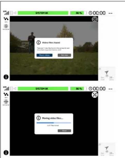
If video files have been recorded during a mission, they can be transferred from the camera SD card to the payload SD card for easier access.
At the end of the flight the pilot is asked if he/she wants to transfer the video files.
The pilot has to confirm the transfer of the video files to the payload SD card. After the confirmation the transfer will occur automatically.
During the transfer a feedback is given on the touchscreen tablet (see image to the left).
After a successful transfer to the payload SD card, the video files will be deleted automatically from the original location on the camera SD card.
If video files are found on the camera SD card, upon powering ON the UAS the next time, the option to transfer them to the payload SD card is again presented.
If you decide to transfer now, the previously taken video files will be transferred to the directory generated for the current flight.
For directly after the current flight transferred videos the following directory- and file structure is valid.
The transferred video files are stored in the same directory on the payload SD card as the image files of the same flight (see above):
- 000001_201802191200 = directory name with a consecutive mission number (000001) date (YYYY/MM/DD) and time (hh/mm)
- MAH00001.MPG = video file with consecutive number (00001)
• MAH00002.MPG = video file number (00002)
• Etc.
2.5.6.1. General care
- Always handle the gimbal with care. If you need to tilt the camera manually (when not connected or while the Intel Falcon 8+ UAV is switched off), please only do so very cautiously. If too much force is applied, the gear wheels of the servo motors may break.
- Because the camera is powered by the Intel Falcon 8+ UAV battery in order to save weight, the camera switches ON or OFF when the UAV is switched ON or OFF.
Note The ON/OFF switch on top of the camera itself has no function.
- Before landing the Intel Falcon 8+ UAV, please remember to adjust the payload tilt to 0^ to avoid damage to the camera or lens, which would occur if the payload is pointing downward when the UAV touches the ground.

CAUTION: DO NOT MOUNT LENS HOODS OR SIMILAR ITEMS THAT ATTACH TO THE FRONT PART OF THE LENS AS THESE MAY BLOCK THE VIEW OF THE FORWARD LOOKING REALSENSE MODULE OF THE OBSTACLE AVOIDANCE SYSTEM.
- Keep the ventilation openings of the payload clean and clear of debris in order for proper cooling of the compute board.
2.5.6.2. Camera control by the CTR
This section describes how to operate the Sony R10C by using the functional elements of the Intel Cockpit CTR.
Figure 2.26: Sony R10C CTR control layout
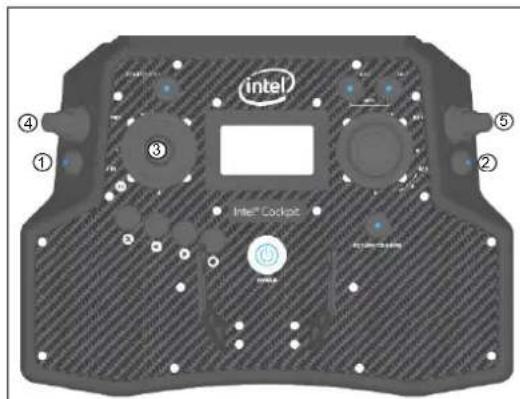
Push Button B1 (1): sets the camera to pre-defined angles +/-90°, +/-45° and 0° when
Rocker Switch R1 (4) is pushed simultaneously (see "Setting the Camera Angle" on page 33 for details).
Rocker Switch R2 (5): by moving this switch up/down the value of the exposure compensation can be set.
Push Button B2 (2): pushing this button resets the exposure compensation to 0.
Push Button B3 (3): photo trigger button
Rocker Switch R1 (4): camera tilt, changes the angle smoothly.
2.5.6.3. Camera settings
After switching the camera ON, the default time is set to 00:00, January 1st 2015 UTC. As soon as a valid GPS signal is available the camera date and time is set directly by the Intel Falcon 8+ UAV using the information embedded in the GPS data.
Adjustable camera settings can be accessed on the left or right side of the screen of the touchscreen tablet of the CTR, when activated by tapping on the respective area in the lower left and right corner.
Figure 2.27: Camera settings by the control menu items on the touchscreen tablet
| GPS SYSTEM OK PATH N NAVIGATOR i PITCH 0° | Tapping, e.g., on the area (1) in the lower left corner of the touchscreen tablet opens a con- trol panel for adjustable camera settings. |
| GPS SY PATH N NAVIGATOR PITCH 0° ZOOM 1x FOCUS AUTO EXP.MODE P EXP.COMP 0.0 AV 7.1 Tv 1/1000 ISO 100 | Depending on lens type and actual camera set- tings different settings are adjustable as shown in the example to the left. The respective setting, in the PITCH example to the left, can be adjusted by dragging the slider depicted to the desired value. |
© 2018 Intel Corporation. All rights reserved 60
For proper operation of the payload, please make sure the Intel Falcon 8+ UAV, the CTR and the touchscreen tablet are updated to the latest available version. Download the Intel Falcon 8+ UAS firmware from http://intel.com/FalconDownloads and install it as described in “Intel® Falcon™ 8+ UAS firmware updates” on page 193.
The payload also contains updateable firmware. To update the payload firmware of the Intel® Imaging Payload you need to install the Intel Platform Flash Tool (PFT) Lite on a PC.
The currently installed firmware version of the payload can be checked by tapping on the "i" INFO button in the lower left corner on the touchscreen tablet.
For updating the payload firmware by the PFT you need:
- Intel Falcon 8+ UAV, with the payload attached. The UAV must be powered OFF in the beginning of the update process.
• PC for running the Intel Platform Flash Tool (PFT) Lite - USB type C to USB type A cable for connecting the payload to the computer (not supplied)
Pre-instructions for upgrading the payload firmware:
- Download and install Intel Platform Flash Tool (PFT) Lite from http://intel.com/FalconDownloads. Please refer to the documentation of the Intel Platform Flash Tool (PFT) for more detailed instructions and supported operating systems.
- Download Intel Android USB drivers from the same website as above mentioned.
- Download the latest payload firmware from http://intel.com/FalconDownloads (in .ZIP file format)
- It is not necessary but we recommend to switch on the Intel Cockpit Controller (CTR) for controlling the flashing process.
Figure 2.28: Firmware update process
![Flash Flash Rev: inquisitions Start is Rev On-issued Rev One device 11/28/17 00:40:05:05# INFO : Using Android Debug Bridge version 1.0.35 version 04/09/06/2014 installed 11/28/17 00:40:05:05# INFO : External tools tax[i][a]: = C:\Program Files (.txt)\real\Phone\Flash\Tool\jdk.exe tax[xeretübolder] = C:\Program Files (.txt)\real\Flash\Tool\eventübolder.exe](/content/2026/05/811574/images/08bfeea6e5ee9a51de757042cb2b95c2c79d3dbb6618fd91a2f6b5ca5869ffb9.jpg)
- Install the downloaded Intel Android USB driver on the same PC you installed the PFT.
- Start the Intel PFT Lite application.
- Open the firmware (.ZIP) file by selecting Browse... in the upper right corner.
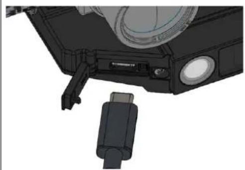
natural_image
3D mechanical component diagram showing a connector with ports and a cylindrical housing (no text or symbols visible)- Open the small hatch on the right side of the payload front side to reveal the USB-C port of the payload.
- Connect one end of an USB type C cable (not supplied) to the port and the other end to the computer running Intel PFT.
Figure 2.28: Firmware update process (continued)

natural_image
Close-up of a mechanical component with textured fabric and a red circular highlight (no visible text or symbols)
CAUTION: DO NOT TURN EITHER THE PAYLOAD OR THE UAV UPSIDE DOWN TO PRESS AND HOLD THE DNX BUTTON. LEAVE THE PAYLOAD IN HORIZONTAL 0° PITCH ANGLE POSITION BECAUSE THE GIMBAL SERVOS OF THE PAYLOAD WILL START WORKING WHEN YOU SWITCH ON THE UAV. THE ACTIVE MOTIONS OF THE SERVOS WOULD WORK AGAINST ANY EXTERNAL FORCE, RESULTING IN POSSIBLE DAMAGE TO THE SERVO MOTORS.
-
Locate the DNX button on the bottom of the payload (next to the USB connector; see picture to the left). The button is accessible through a small hole on the bottom of the payload. The button can be pressed by using a straightened paper clip or similar object.
-
Insert the paper clip into the hole and press the button. When doing this a click can be heard.
-
While keeping this button pressed down, power ON the Intel Falcon 8+ UAV. This will put the payload into the firmware update mode.
-
The DNX button can be released approximately 5 seconds after switching ON the Intel Falcon 8+ UAV.
Figure 2.28: Firmware update process (continued)
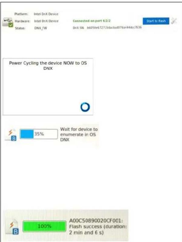
In Intel PFT wait for Intel DnX Device to appear.
- Tap/click on the Start to flash button to start the firmware update process. The flashing process starts.
After a while the note Power Cycling the device NOW to OS DNX will appear and the payload will restart.
After the payload restarts, the update process will continue and the progress indicator will show Wait for device to enumerate in OS DNX.
During the flashing process, the Intel PFT will be delayed at around 86% for a short time but continue.
After the update is completed, the progress indicator turns green and depicts the message pictured to the left.
- Disconnect the USB cable now from the payload but leave the payload and the UAV powered on.
After around 40 - 50 seconds the payload reboots for the first time.
After around 2 minutes and 40 - 50 seconds, the second boot is almost complete.
After around 3 minutes and 10 seconds, the viewfinder image on the touchscreen tablet of the CTR appears (if switched on before). If the CTR is ON, it is possible to see the BIOS boot screen and also the Intel logo two times.
After the flashing process it is necessary to power the UAV OFF and then ON again.
2.5.6.5. Obstacle Avoidance (OA)
Obstacle Avoidance (OA) enables the Intel Falcon 8+ UAV to get depth perception of its surroundings. This is enabled by two Intel® RealSense™ Depth Cameras, mounted on the payload, one looking towards the front and another looking 90 degrees to the left. Together they enable an approximate 180 degree view from side to side.
OA only works with supported payloads. When connecting the Intel Imaging Payload, the OA feature in the user interface of the touchscreen tablet of the Intel Cockpit Controller (CTR) becomes activated and enables the pilot to activate or deactivate OA.
Conditions for using Obstacle Avoidance
OA responsiveness increases with textured surfaces. The greater the amount of texture, the more accurate depth information will be gathered by the Intel RealSense cameras.
!
CAUTION: SURFACES THAT ARE LESS SUITED FOR OA ARE, E.G., CLEAN WINDOWS AND OTHER REFLECTING SURFACES AT BRIGHT SUNLIGHT AS THESE SURFACES MAKE IT DIFFICULT TO DISTINGUISH THE DEPTH OF THE SURFACE, MEANING THE SURFACE WOULD GO UNDETECTED.
NOT EVERY OBSTACLE WILL BE DETECTED BY THE OBSTACLE AVOIDANCE CAPABILITY. IT IS STRONGLY RECOMMENDED THAT THE PILOT BECOMES ACCUSTOMED TO THE CAPABILITIES AND REACTIONS OF THE INTEL FALCON 8+ UAV WITH OA BY PERFORMING TEST FLIGHTS UNDER CONTROLLED CONDITIONS. IF IN DOUBT WHETHER AN OBSTACLE IS DETECTABLE, TRY IT FIRST IN A CONTROLLED AND SAFE ENVIRONMENT, OR WITH THE HELP OF A SPOTTER AND AT LOW SPEED.
ALWAYS BE PREPARED DURING ANY FLIGHT TO DEACTIVATE OA AND TAKE OVER THE CONTROL OF THE UAV TO STEER AWAY FROM POTENTIAL OBSTACLES IN CASE OA DOES NOT REACT AS EXPECTED.
OBJECTS DIRECTLY ABOVE AND BELOW THE UAV ARE NOT DETECTED EVEN IF THE CAMERA IS POINTING IN THAT DIRECTION!
Please pay special attention to the following points:
- Keep the lenses of the OA modules clean and check them before every flight.
- OA is inactive when performing automated flights; e.g. waypoint flights.
- OA is inactive during RETURN TO HOME and Link Loss Procedures procedures.
- OA is able to stop the drone in front of an object when flying up to 4.5m/s (= standard max. velocity in GPS mode). If the pilot flies at higher speed in Height-or Manual-Mode, and then switches to GPS-Mode with OA ON, the drone may not be able to stop in front of an object in time due to the speed.
- If flying in an altitude lower than the set standoff distance, OA will still seek to avoid collisions, but the set standoff distance may not be maintained.
- When flying between structures always make sure that the set standoff distance can be maintained in all directions.
• OA may not recognize:
• water and other transparent surfaces
• uniformly colored surfaces, like white walls
• surfaces with no clear texture
- small objects like tree branches.
- OA performance may get degraded, e.g.: stopping too early, seeing objects late, not maintaining the set standoff distance under the following circumstances:
• surfaces with repetitive patterns, like tiling or corrugated iron
- low light conditions
- fog/snow/rain
- flying straight towards low sun, after/before sunrise/sunset
- flying between buildings/structures, where GPS signal may get obstructed.
Figure 2.29: Obstacle Avoidance: directions covered
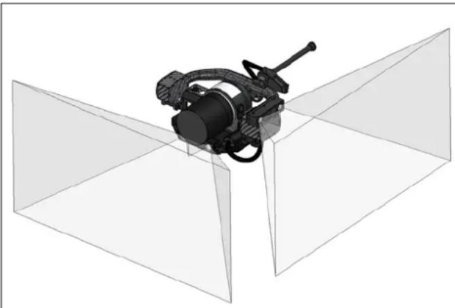
natural_image
3D technical illustration of a mechanical device mounted on a structural plane (no text or symbols visible)Each RealSense module covers a field of view of 91.2 degrees horizontally and 58.0 degrees vertically. With one module facing forward and one 90° sideways to the left, a total field of view of approximately 180° is created.
The two different cones of the two RealSense modules touch each other in a distance approximately 2600 mm from the camera.

CAUTION: THE UAV CANNOT DETECT ANY OBSTACLES OUTSIDE OF THE ABOVE-DESCRIBED FIELDS OF VIEW.
Configuring Obstacle Avoidance
The following figure shows the user interface of the touchscreen tablet of the CTR upon connecting an OA supporting payload and opening the OA settings panel.
Figure 2.30: Tablet GUI with an OA payload mounted
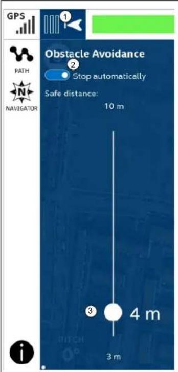
Please note that OA is always switched OFF by default upon powering ON the Intel Falcon 8+ UAV, and OA cannot be switched ON while the UAV is on the ground.
The OA indicator and button on the top left (1) shows the status of OA. A light grey color indicates OA is turned OFF. A black color indicates that OA is turned ON.
Tapping on this button opens the OA settings panel as shown to the left.
Tapping on the toggle (2) inside of the settings panel activates or deactivates Obstacle Avoidance.
The slider inside of the panel (3) allows the pilot to set the standoff distance from objects and obstacles.
The standoff distance can be set between the minimum and maximum shown in the OA setting panel.
Turning the OA feature ON and OFF:
- Start the Intel Falcon 8+ UAV and take-off in GPS-Mode (if possible).
-
Tap on the OA indicator and button in the top left corner of the touchscreen tablet screen.
The OA set panel is opened. -
Drag the slider inside of the panel to adjust the desired standoff distance. The set value is shown.
-
Tap on the OFF/ON toggle on top of the OA settings panel one time to turn ON OA. The OA indicator field will go black. This indicates that OA is activated.
-
Tap on the OA indicator again. The OA settings panel is closed.
To deactivate OA open the OA set panel as described and tap on the OFF/ON toggle one time to turn OFF OA. The OA indicator field goes light gray.
The OA indicator and button (number (1) above) also shows the approximate distance to an object measured by the RealSense modules visualized by 3 bars. When a bar is filled (black) a value is reached.
Value distribution for the bars:
- 0 bars: the distance to the next obstacle is 3 times greater than the standoff distance set by the pilot
- 1 bar: the distance is between 3 times and 2 times of the set distance
• 2 bars: the distance is between 2 times and 1.5 times of the set distance - 3 bars: the distance is between 1.5 times and the set distance
Table 2.6: Example for a hold distance set to 5 m
| BARS FILLED | DISTANCE TO OBSTACLE IN METER |
| 0 bar > 15 m | |
| 1 bar 10 m - 15 m | |
| 2 bars 7.5 m - 10 m | |
| 3 bars 5 - 7.5 m |
When the minimum standoff distance set by the pilot is reached while moving forward or left, the UAV stops moving farther. If the distance decreases more (e.g. because of a wind gust), the OA indicator starts flashing. The flashing stops once the distance is again equal or greater than the set standoff distance.
Obstacle Avoidance and Flight Modes
Depending on the activated flight mode (GPS-Mode, Height-Mode or Manual-Mode), there are differences in how OA works.
GPS-Mode and Distance Hold
In GPS-Mode, the UAV performs a “sense and stop” action when OA is activated. As soon as it reaches a user defined standoff distance to the obstacle (see section “Configuring Obstacle Avoidance” on page 67 for further details), it will maintain this currently adjusted standoff distance. The pilot cannot fly any closer than the set distance and control commands from the CTR that would reduce this distance are not executed by the UAV.
While GPS-Mode is active, the UAV creates an obstacle map, which is populated with the obstacles that were previously detected. The absolute GPS coordinates of each detected obstacle are stored. This makes it possible to avoid previously detected obstacles, even if they are currently outside of the direct field of view of the RealSense modules.
Note
For safety purposes, always orient the UAV such that a RealSense module points in the direction of flight.
Height-Mode and Distance Guard
If OA is active and Height-Mode is activated, either by the pilot on the CTR or automatically by the UAS in case the GPS signal quality is not sufficient, Obstacle Avoidance works as a Distance Guard.
Note
Deletion of the obstacle map that was populated in GPS-Mode occurs if the GPS reception is lost due to insufficient signal quality. Because the information contained in the map is no longer available, the UAV can no longer avoid obstacles outside of the direct field of view of the RealSense modules. If the GPS reception is re-established, the UAV will start to populate the map again with detected obstacles.
The Distance Guard mode detects obstacles which are within the field of view of the RealSense cameras, and actively steers the UAV into the opposite direction of an obstacle when the user-set standoff distance is reached. There is no position control in Height-Mode and the UAV will always drift depending on the environmental influences.

CAUTION: A COLLISION OF THE UAV WITH A DETECTED OBSTACLE MAY OCCUR IF THE PILOT GIVES A STRONG STICK COMMAND IN THE DIRECTION OF THE DETECTED OBSTACLE SUCH, THAT THE COMMAND OVERRIDES THE DISTANCE GUARD!
Manual-Mode
Obstacle Avoidance is always disabled in Manual-Mode.
Landing the UAV with Obstacle Avoidance
During a descent of the UAV, if any obstacle comes into the field of view of the Intel RealSense modules within the pilot-set standoff distance, the UAV may fly backwards or sideways towards the pilot to keep the defined standoff distance. To avoid such a situation, always switch OFF OA before descending to land the UAV.
OA system warnings
The following warnings can appear in the notification area on top of the touchscreen tablet and/or in the bottom line of the Status Display.
Table 2.7: System warnings related to Obstacle Avoidance
| SHOWN TEXT | REASON | SUGGESTED SOLUTION |
| Tablet:ObstacleAvoidance not available!Status Display:OBSTACLEAVOID. N/A!(Obstacle Avoidance not available)In case of these text messages the CTR will also vibrate. | The RealSense modules cannot be accessed and Obstacle Avoidance is not available. | If the warning occurred during the start of the UAS, try restarting it. If the message does not reappear, the connection to the RealSense modules has been re-established.If in flight and in GPS-Mode the Intel Falcon 8+ UAV will keep its current position. To avoid collisions the control sticks will be disabled until the pilot has switched OFF Obstacle Avoidance. When Obstacle Avoidance is deactivated, the pilot has control of the control sticks again.If this warning appears when the UAV is in flight and in Height-Mode, the pilot must immediately steer away from any obstacle. |
| Tablet:Switched to Distance Guard! | The Intel Falcon 8+ UAS has automatically switched from GPS-Mode to Height-Mode (due to insufficient GPS quality) and Obstacle Avoidance now works in Distance Guard mode. See “Height-Mode and Distance Guard” on page 69 for further details. | If the UAV automatically switches to Height-Mode (HGT shown in the top right corner of the touchscreen tablet, H shown in the top right corner of the Status Display, GPS button on CTR is flashing), Intel strongly recommends that the pilot manually activates Height-Mode on the CTR. This way any unexpected switch of the flight mode can be avoided.Continue to fly in Height-Mode if you are sufficiently trained. Otherwise land the system and only fly in areas with sufficient GPS signal quality. |
2.6. THE INTEL® POWERPACK BATTERIES
The Intel® Powerpack batteries power the Intel® Falcon™ 8+ UAV and the Intel® Cockpit Controller (CTR). The battery features a One-Button/Five-LEDs user interface, an intelligent Battery Management System (BMS), automatic balancing, storage mode and charging. It provides direct access to general information of the battery; for example, the remaining battery life, which is shown by the five LEDs (see “Operating The BMS Menu” on page 74).
The BMS safely monitors the status of each of the four cells of the battery to ensure a safe charging process. Its cell balancing technology assures the consistency in the performance of the batteries.
The following sections give you information about the Intel® Powerpack batteries you need for the Intel® Falcon™ 8+ UAV and the CTR.
For charging an Intel® Powerpack Battery you need one of the deliverable power supply units.
Table 2.8: Technical Specifications of the Battery
| BATTERY TYPE | ELECTRIC CHARGE [MAH] | VOLTAGE STANDARD [V] | VOLTAGE FULLY CHARGED [V] | VOLTAGE LOWEST RECOMMENDED (UNDER LOAD) [V] | NO. OF CELLS |
| Intel®PowerpackTMBattery | 4000 14.8 1 | 6.8 14.0 4 |
On the front panel of the battery there is a sticker. An area is marked by a dot surrounded by a circle (see figure below). This area has the function of a button.
Figure 2.31: LED description
| 1 2 3 4 5 Push to check battery | The LEDs are integrated in the front panel of the battery. LED number / color from left to right: • 1 / red • 2 / yellow • 3 / green • 4 / green • 5 / green |
Please note the limitations mentioned on the labels of the Intel® Powerpack Battery.
Figure 2.32: The Intel® Powerpack Battery
| Intel® Powerpack Rechargeable Lithium Polymer Battery SB-0102-002 4ICP7/45/131 14.8V | Intel Corporation 2200 Mission College Blvd Santa Clara, CA 95054 Made in China |
| WARNING: To reduce risk of fire, do not disassemble, crush, or puncture; do not short external contacts; do not dispose of in fire or water. Unintended or improper use can lead to risk for the user or third persons, and cause serious damage to property. Strictly follow the manual, warnings and safety instructions. ATTENTION: Afin de limiter les risques d'incendie, il est strictement interdit de démonter, d'écraser, de broyer ainsi que de percer [la batterie], de mettre ses contacts a nus, de la mettre en cours circuit, ou de la déposer dans l'eau ou dans le feu. Un usage inapproprié ou non prévu par les conditions d'utilisation peu comporter des risques pour l'utilisateur et/ou des personnes tierces et peut causer de sérieux dommages matériels. Il est impératif de se conformer aux instructions de sécurité du manuel. | S/N DANGER: Do not drop, dispose of in fire, short circuit or overcharge. Only for use in Intel Falcon 8+ systems. Use only the charger provided. Store batteries in a cool place. Do not store fully charged or discharged batteries. Operation up to max. 40°C /102°F, never charge unattended and store in nonflammable environments. DO not charge above 40°C. Recycle the battery, if it is deep discharged, inflated or damaged. This device complies with part 15 of the FCC Rules. Operation is subject to the following two conditions: (1) This device may not cause harmful interference, and (2) this device must accept any interference received, including interference that may cause undesired operation. UN 38.3, IEC 62133, UL/CSA 62133 CAN ICES-3(B)/NMB-3(B) |
Even if the battery is not in use, it is possible to get information on the actual charging state by the BMS. One short push (< 2 sec) on the button (shown above) and the battery will show the charging state represented by the respective number of LEDs.
Table 2.9: Charging State
| THE LEDS SHOW THE STATE / PHASE OF CHARGE OF THE BATTERY. | |
| STATUS OF LED NO. 1 2 3 4 5 CHARGING STATE | |
| ON OFF OFF OFF OFF 0% - 20% | |
| ON ON OFF OFF OFF 20% - 40% | |
| ON ON ON OFF OFF 40% - 60% | |
| ON ON ON ON OFF 60% - 80% | |
| ON ON ON ON ON 80% - 100% | |
2.6.1. Charging the Intel® Powerpack Batteries
Upon receipt of new Intel® Powerpack Batteries, you should charge them to 60 - 80% to ensure batteries will not completely drain in storage. To charge the batteries, please use the provided power supply unit.
Figure 2.33: Charging
| Inter Powerpack Powerpack Battery Powerpack Battery to the adapter of the power supply unit. Connect the power supply unit to a wall socket. Charging will begin immediately indicated by flashing LEDs. | To charge the Intel® Powerpack: 1. Connect the Intel® Powerpack Battery to the adapter of the power supply unit. 2. Connect the power supply unit to a wall socket. Charging will begin immediately indicated by flashing LEDs. |
During the charging process (defined as when the battery is connected to the power supply unit and the power supply unit is connected to a wall outlet 100 V - 240 V AC 50 Hz - 60 Hz) the actual battery state and the progress of the charging process is automatically shown by the LEDs.
As displayed in the table above, the number of permanently lighted LEDs shows the actual progress of charging. Additionally, the next higher LED is flashing. This means that this charging step is not yet finished.
When the charging process is finished and the battery is at full capacity, all five LEDs will continue flashing simultaneously.
When charging is finished, unplug the battery and the AC adapter.
The Intel® Powerpack Battery has an internal timer which keeps the battery turned ON for 3 seconds after unplugging it from the charger. When a battery with LEDs illuminated is plugged into the Intel Falcon 8+ UAV or the Intel Cockpit Controller (CTR), the respective unit powers ON automatically without the user pressing the ON/OFF button. To prevent automatic power ON, wait until the battery LED lights are no longer illuminated before inserting it into the Intel Falcon 8+ UAV or the CTR.
2.6.2. Operating The BMS Menu
For further information about the battery you can activate the BMS menu. The battery does not need to be connected to the power supply unit to activate the BMS menu.
To activate the menu:
- Push/hold down the button (> 2 sec). When the first LED (no. 1, red) is flashing, the first menu option can be activated by another long push (> 2 sec) on the button.
- Every further short push (< 2 sec) on the button navigates to the next menu option which can be activated by another long push (> 2 sec) on the button, indicated by the flashing of the respective LED.
If there is no user input, the LED menu will close after 33 seconds.
The five menu options are the following:
Menu Option 1, Charging State
When LED 1 is flashing, menu option 1 can be activated. When activated the LEDs show the state of charge of the battery (see “Charging State” on page 73). After showing the state of charge of the battery for 8 seconds, the menu is closed automatically (all LEDs off).
Menu Option 2, Storage Mode
When LED 2 is flashing, Menu Option 2 can be activated. When you select this option by pushing/holding down the button for more than 2 seconds, the battery Storage Mode is activated. When this mode is activated, all but one LEDs are on. The off-LED moves from right to left.
In the Storage Mode, the BMS automatically balances the battery down to 3.8V / Cell (= 15.2 V per battery). The battery Storage Mode can be deactivated by pushing the battery button for more than 2 seconds.
We recommend using this mode when you have fully charged the battery (80-100%), but plan to store the battery for 2 days or longer.
Since there is only a small resistive load, it will take a very long time to discharge full batteries to the storage voltage. To facilitate discharge, use fully charged batteries in the Intel® Cockpit Controller or Intel® Falcon™ 8+ UAV before they are stored.
Menu Option 3, Charging Cycles
When LED 3 is flashing, menu option 3 can be activated. The LEDs show the current battery charging cycles, i.e. how often the battery was charged.
The total number of charging cycles of the battery is shown by the LEDs in a binary system by powers of 2 from right to left multiplied by 10.
Table 2.10: Charging Cycles
| THE LEDS SHOW THE TOTAL NUMBER OF CHARGING CYCLES OF THE BATTERY FROM RIGHT TO LEFT BEGINNING WITH LED 5 (GREEN) = 20, THIS NUMBER SHOULD BE MULTIPLIED BY 10 | |
| STATUS OF LED NO. 1 2 3 4 5(EXAMPLES) | CHARGING STATE |
| OFF OFF OFF OFF ON | 20 = 1 X 10 ≧ 0 - 10 |
| OFF OFF OFF ON OFF | 21 = 2 X 10 ≧ 11 - 20 |
| OFF OFF OFF ON ON | 20 + 21 = 3 X 10 ≧ 21 - 30 |
| OFF OFF ON OFF ON | 20 + 22 = 5 X 10 ≧ 41 - 50 |
| OFF ON ON ON ON | 20 + 21 + 22 + 23 = 15 X 10 ≧ 141 - 150 |
Menu Option 4, Overall Capacity
Menu option 4 shows the current possible amount of charge the battery may hold when fully charged (as a percentage) compared to the factory battery capacity.
Table 2.11: Battery Capacity
| THE LEDS SHOW THE CURRENT POSSIBLE BATTERY CAPACITY AS PERCENTAGE COMPARED TO THE FACTORY BATTERY CAPACITY | |
| STATUS OF LED NO. 1 2 3 4 5 REMAINING CAPACITY | |
| ON OFF OFF OFF OFF 51% - 60% | |
| ON ON OFF OFF OFF 61% - 70% | |
| ON ON ON OFF OFF 71% - 80% | |
| ON ON ON ON OFF 81% - 90% | |
| ON ON ON ON ON > 90% | |
Menu Option 5, Battery Status
Menu option 5 shows the difference (as a percentage) between the highest measured cell voltage and the lowest measured cell voltage, measured at the same time.
The BMS tries to balance the charging status of all 4 battery cells to the same level. By measuring the difference between the highest cell voltage and the lowest cell voltage, the actual battery status is determined. This status can be shown by activating menu 5.
Table 2.12: Battery Status
| THE LEDS SHOW THE STATUS OF THE BATTERY | ||
| STATUS OF LED NO. 1 2 3 4 5 | VOLTAGE DIFFERENCE | MEANING |
| OFF OFF OFF OFF OFF <= 5% | Best, the battery can be used | |
| ON OFF OFF OFF OFF > 5% | Still everything fine | |
| ON ON OFF OFF OFF > 10% | Battery still usable | |
| ON ON ON OFF OFF | > 15% | Bad, think about changing the bat-tery |
| ON ON ON ON OFF | > 20% | Very bad (the battery might still be used in the CTR) |
| ON ON ON ON ON | > 25% | Worst (e.g. 3.8 V on the highest and 2,85 V on the lowest cell, measured at the same time), the use of the bat-tery is no longer possible |
To get a comparable result, this battery status check is done best directly after use/ flight.
BMS Error Mode
If during the charging process the LEDs are lit alternatively LED2 and LED4 ON with LED3 ON, the charging process is interrupted for one of the following reasons:
• The battery cells are too hot or too cold
• Charge Control Circuitry too hot
The charging process will resume automatically once the temperature of the cells is normalized.
When the battery shows LED1 ON and LED5 ON alternating with LED2 and LED4 ON, the battery was operated out of specifications (e.g. too hot during discharge).
When a battery shows this behavior, it can still be used to discharge its remaining capacity, but it must not be used anymore.
When you have a battery showing this error mode, push the battery button once. As a result, a few LEDs will be lit. Please either take a photo of the lit LEDs or note which ones are lit (no. 1 is the LED most left, no. 5 is the LED most right). Contact the support team at Intel and provide the information which LEDs are lit. In case this state became active during a flight, please also provide a log file of this flight.
If you see any other behavior of the LEDs contact Intel Support.
2.6.3. Battery Update
The firmware version of the BMS is automatically managed by the firmware of the UAV. As soon as a battery is inserted into the UAV and used, the firmware version of the battery is checked. If the firmware version of the BMS on the battery is older than the one currently installed on the UAV, it will be noted and the battery will be updated automatically by the UAV.
During this process, which takes less than a minute, a message is shown in the status line at the bottom of the Status Display (see “STATUS DISPLAY” on page 166) and it is not possible to start the UAV.
Figure 2.34: Battery Update
| Battery | 1 | 2 | B | |
| Current Voltage Charge Error | 0 168 97 0 | 1 165 % 0 A dV % 0 | BA T | The progress of the battery update process is shown in percent in the status line at the bottom of the Status Display. It can take up to maximum 1 minute. During this period it is not possible to start the UAV. |
| BATTERY UPDATE: 42% | ||||
2.6.4. Battery Information Safety Instructions And Warnings

CAUTION: PLEASE READ THE FOLLOWING SAFETY INSTRUCTIONS AND WARNINGS CAREFULLY BEFORE CHARGING OR USING THE BATTERIES!
INTEL CANNOT ASSUME ANY LIABILITY FOR FAILURES TO COMPLY WITH THESE WARNINGS AND SAFETY GUIDELINES.
- Lithium Polymer (LiPo) batteries do not have any memory effect. Never fully discharge LiPo batteries, as it will permanently damage the batteries.
- Do not store batteries fully charged. It will lead to a shorter life span of the battery. Use the BMS battery Storage Mode for long-term storing (> 2 days) (See Operating The BMS Menu, “Menu Option 2, Storage Mode” on page 74.
- LiPo batteries are volatile. Failure to read and follow the below instructions may result in fire, personal injury and damage to property if charged or used improperly.
- The battery charging/discharging and storage area should be free from any materials which can catch fire such as: wood tables, carpet, or gasoline containers. The ideal surface for charging and storing LiPo batteries is metal, concrete or ceramic.
• Extinguishing Media: Water, CO2.
• Special Fire-Fighting Procedures: Self-contained breathing apparatus.
- Unusual Fire and Explosion Hazards: Cell may vent when subjected to excessive heat-exposing battery contents.
- Hazardous Combustion Products: Carbon monoxide, carbon dioxide, lithium oxide fumes.
- By purchasing this battery, the customer assumes all risks associated with lithium batteries. If you do not agree with these conditions, return the battery immediately before use.
General Guidelines and Warnings
- It is crucial that all cells in a LiPo battery maintain the same voltage across all cells at all times.
- Never charge batteries unattended. When charging LiPo batteries, you should always remain nearby to monitor the charging process and react to potential problems that may occur.
- Never continue to charge LiPo batteries if the battery LEDs fail to recognize full charge. Overheating of the LiPo cells indicates a problem. In the event of overheating, the battery should be immediately disconnected from the power supply and placed in a fireproof location.
- Since delayed chemical reaction can occur, it is best to monitor the battery as a safety precaution. Battery monitoring should occur in a safe area outside of any building or vehicle, and away from any combustible material. Always charge LiPo batteries in a fireproof location.
- A battery can ignite even after the charging process has been completed.
- In the event of a crash, you must remove the battery for observation and place it in a safe open area away from any combustible material for an appropriate period.
- Never store or charge a battery inside of your car in extreme temperatures, since extreme temperature could cause a fire.
Charging
- Before charging, visually inspect the battery. Look for any damaged connectors or other irregularities. Do not use it if you find any of the above issues with your battery.
- If any damage to the battery is found or if the voltage is significantly less for your battery than what is specified below, do not attempt to charge or fly with the battery; contact your supplier.
- Never charge batteries unattended.
- Charge in an isolated area, away from flammable materials. Use deliverable LiPo-safe bags or a non-flammable case for charging.
- Let the battery cool down to ambient temperature before charging.
- You may witness a battery starting to balloon or swell up. This may lead to a deformed housing where the battery no longer fits into the UAV battery compartment. If you notice such a deformation, do not start charging this battery. If you already started charging, discontinue the charging process immediately. Disconnect the battery and observe it in a safe place for an appropriate period. Continuing to charge a battery that has begun to swell will result in fire. Never use a battery if you find it swollen or ballooned.
Discharging
Do not discharge a battery to a level below 3.5 V per cell. Deep discharging a battery cell below 3.5 V can reduce battery performance or even destroy the battery.
Storage & Transportation
New batteries are delivered with less than 30% charge, to comply with regulations which allow Li-Po batteries to ship via air. Because the battery slowly self-discharges, it is important to maintain battery charge state, and periodically check batteries charge level to avoid deep discharge. Therefore, Intel recommends charging batteries periodically when in storage according to the instructions provided in this chapter.
The Intel® Powerpack Battery has an internal Battery Management System (BMS) which must use the battery power to use the charging circuit. If the battery's power level is allowed to drain to a “zero state”, the battery will not be able to recharge due to safety limits that prevent charging a deeply-discharged battery, which is not recommended. However, storing a fully charged battery has negative effects on its life span.
Battery Storage/Charging Maintenance Recommendation
- Intel recommends to charge/recharge batteries to a level between 2 and 4 LED's (40-80%) every 3 months to maintain optimal cell performance and reliability.
- If a battery is charged to 100% (5 LED's), but needs to be stored, it can be put back into safe voltage level by activating Battery Storage Mode. (see Operating The BMS Menu, "Menu Option 2, Storage Mode" on page 74).
-
Only completely charge batteries immediately before the next flight.
-
Always store batteries within the specified temperature ranges. See "TECHNICAL SPECIFICATION" on page 218 for further details.
- Do not expose batteries to direct sunlight or heat for extended periods.
- For transporting and storing the batteries, use LiPo-safe bags or cases.
Caring for Batteries
- Please check the battery voltage after charging. It is shown on the Main Screen of the Status display and by the LEDs of the battery.
- The voltage for a 4-cell battery should fall between 16.4V - 16.8V .
- Do not discharge batteries to a level below 14 V. Deep discharge below 14 V will deteriorate the battery performance.
- Never puncture the battery cells. Punctured cells may cause fire.
Operating Temperatures
Refer to “TECHNICAL SPECIFICATION” on page 218 for details regarding operating temperatures.
Figure 2.35: Temperature Depending LiPo Battery Capacity
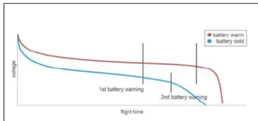
line
| flight time | battery warm | battery cold | | ---------- | ------------ | ------------ | | 0 | 1 | 1 | | 1st battery warning | ~0.8 | ~0.6 | | 2nd battery warning | ~0.7 | ~0.4 |The capacity of LiPo batteries drops dramatically if the temperature is below 5^ C. Please keep the batteries warm when flying in cold conditions or heat them up before flying to approximately 30^ C.
Battery Life
Batteries that have lost 20% of their capacity (see Operating The BMS Menu, "Menu Option 5, Battery Status" on page 76) must be removed from service and disposed of properly.
Disposal
For proper treatment, recovery and recycling, please take these products to designated collection points where they will be accepted on a free of charge basis. Alternatively, send the battery for disposal back to Intel. Disposing of this product correctly will help to save valuable resources, and prevent any potential negative effects on human health and the environment, which could otherwise arise from inappropriate waste handling. For disposal, please discharge the battery to 3V or below per cell, then wrap the battery in a bag for disposal.
Product Warranty
Product warranty is limited to original defects in material and workmanship. Warranty does not cover collateral damage. Due to the nature and use of this product there is no long-term warranty. Misuse, abuse, incorrect charging, failure to comply with the above warnings and guidelines, and other inappropriate use of this product are not covered under warranty.
2.7. TRANSPORT CASES & INTEL® BACKPACK
The transport set consists of different cases with precision water jet cut inlays designed for the Intel® Falcon™ 8+ UAS with all its accessories. For easy one-person transportation, the Intel® Falcon™ 8+ UAS cases have retractable handles and wheels. The Intel® Backpack is not safe for air freighting, but very useful for missions in remote areas, since it is light and relatively compact.
Figure 2.36: Transport Cases & Backpack
| The transport cases offer great advantages: • Thanks to fold-able handles and wheels, they can be easily transported by one per- son. • The foam bolster inlay of the payload case can be used as load security for the payload when the UAV is transported with mounted payload in the Intel® Falcon™ 8+ UAV case. If transported by plane - please follow the pre- scribed guidelines from the air freight carrier. |

CAUTION: THE INTEL® FALCON™ 8+ UAV AND THE INTEL® COCKPIT CONTROLLER (CTR) MUST BE TRANSPORTED FULLY ASSEMBLED. FOR SECURE TRANSPORTATION WE RECOMMEND USING THE SUPPLIED CASES.
2.7.1. Packing Instructions
To ensure a safe and optimal transport of your flight system, please see the images below for the right boxing.

CAUTION: WHEN SHIPPING THE INTEL® FALCON™ 8+ UAV IN THE TRANSPORT CASE WITH A MOUNTED PAYLOAD, YOU MUST USE THE FOAM INLET OF THE PAYLOAD CASE TO AVOID DAMAGES DURING TRANSPORT OR YOU MUST TRANSPORT IT IN THE SPECIAL PAYLOAD CASE (SEE FOLLOWING).
Figure 2.37: Packing Instructions for the Intel® Falcon™ 8+ UAS Cases
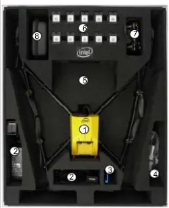
Intel ^® Falcon ^TM 8+ System Case
This case is used for all necessary parts of your Intel ^® Falcon ^™ 8+ UAV.
Following the numbers, the slots contains:
(1) Intel ^® Falcon ^™ 8+ UAV without payload
(2) Power supply units for charging the Intel® Powerpack batteries (6)
(3) Space for accessories, e.g. sunglasses
(4) Toolkit with spare propellers (see below)
(5) Space for the payload when mounted directly on the UAV.
For load security, you must take the foam bolster inlet supplied with the payload case.
(6) Space for the Intel ^® Powerpack batteries (optional, shipped separately)
(7) ICC gamepad (optional)
(8) Space for extra equipment, if any, that is not part of the System, e.g. reflective safety vest or video goggles
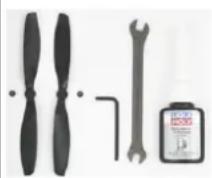
Toolkit and spare parts
Figure 2.37: Packing Instructions for the Intel® Falcon™ 8+ UAS Cases (continued)
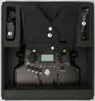 | Intel® Cockpit Controller (CTR) CaseThis case contains:CTR with mounted sun shield(1) When transporting the CTR in the case, the sunshield must be arranged like shown to provide extra protection of the touchscreen tablet against scratches during transportation.(2) Additional space(3) Additional space e.g. for an extra power supplyIncluded in the case but not shown: Shoulder harness is underneath the sun shield protected touchscreen tablet. |
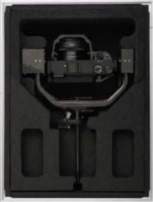 | Payload CaseThe payload of the Intel® FalconTM 8+ UAS must be placed as shown on this image. Make sure that it is placed conveniently inside of the foam bolster. The foam bolster cover (not shown) on top of the payload should be used to secure the payload when it is transported mounted on the UAV in the Intel® FalconTM 8+ UAV case. |
Figure 2.37: Packing Instructions for the Intel ^® Falcon ^™ 8+ UAS Cases (continued)
| Intel® Backpack The backpack is the optimal solution to transport the complete UAS over rough terrain or on longer walks. When placing the UAV into the backpack always align the bottom two propellers (in the image on the top, with the Intel® Falcon™ 8+ UAV facing down) parallel to the top of the backpack like shown in the image. The other propellers are oriented parallel to the motor rails. (1) Use the four big Velcro tapes to secure the Intel® Falcon™ 8+ UAV inside the backpack. They should be very tight so that they "lift" the system up, and away from the CTR. (2) At the bottom part, there is space for the CTR. Before placing it inside of the backpack make sure that the sun shield is arranged as shown in the image to protect the touchscreen tablet and that you secure it with the Velcro tape. (3) On the outside, there are two separate pockets for the Intel® Powerpack batteries. Another large pocket is located on the lid (not shown in the image). There is enough space for items such as another Intel® Powerpack battery, the power supply unit or a notebook and the shoulder harness. |
| The images of the items above are just for illustration purpose and the actual item(s) packed with your Intel® Falcon™ 8+ UAS may differ from the one(s) depicted here depending on, for example, which payload you ordered. |
2.7.2. Packing for shipping
When you got your Intel® Falcon™ 8+ UAS delivered, the system case was encased in a cardboard box. In case you need to send back the UAV system, please pack the system in the respective case like described above. For shipping it, please additionally use the cardboard box in which the system case was covered when it was delivered and pack it as described in the following instructions.
Figure 2.38: Packing Instructions for the cardboard box for the UAV system case
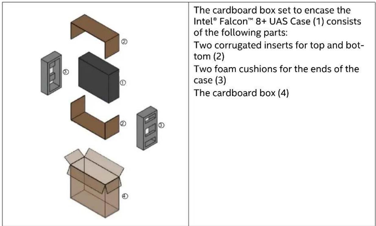
Figure 2.38: Packing Instructions for the cardboard box for the UAV system case
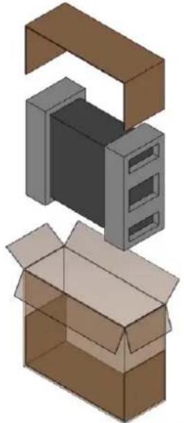 | To pack the system case into the card-board box follow the steps like described:1. Place one of the corrugated inserts into the bottom of the box.2. Place the two cushions over the ends of the case. |
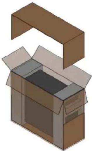 | 3. Load the case equipped with the cushions into the box. |
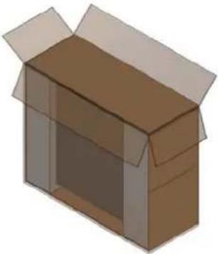 | 4. Place the second corrugated insert over the top of the cushioned case and close the box. |
Figure 2.38: Packing Instructions for the cardboard box for the UAV system case
| 5. Seal the closed box with shipping tape using the 6-strip method, 3 strips on top and 3 strips on bottom as shown. |
2.8. SOFTWARE FEATURE PACKAGES
There are optional software feature packages available for the Intel ^® Falcon ^™ 8+ UAS. They offer useful functions for specific applications.
There are two different licensing models for obtaining the software feature packages.
- One option is a perpetual software license that remains on the UAV. The advantage of a perpetual license is that it remains on the UAV and can be used with any payload.
- The other option is an annual software license. This is stored on the payload, and the license terminates one year after the activation date if the subscription is not renewed. The advantage of an annual license is that it can be used with one payload on any Intel Falcon 8+ UAV.
The available software feature packages can be purchased at any time and unlocked remotely by your Intel® Falcon™ 8+ UAS reseller. The Intel® Falcon™ 8+ UAS does not need to be sent back.
- When ordering a perpetual license, please provide the serial number of the UAV, which can be found on top of the central unit and as well via the Status Display (see "Perpetual Software Feature Packages" on page 90).
- When ordering an annual license, please provide the serial number of the payload. (see "Annual Software Feature Packages" on page 90).
Please find detailed instructions on how to unlock software feature packages in "Activating Software Feature Packages" on page 89.
Table 2.13: Package Descriptions
| FUNCTIONALITY DESCRIPTION | |
| SURVEY PACKAGE | |
| Flight planning Fly | and survey areas fully automated. You can plan complex waypoint missions on your notebook with the flight planning AscTec Navigator Software even before you go out in the field. In the near future AscTec Navigator will be replaced by the advanced flight planning software Intel Mission Control. For up to date information, please check: http://www.intel.com/IntelMissionControl |
| Quick survey This function lets you generate an automated survey flight while in the field (without notebook) within seconds. Set the ground sample distance (GSD), the area to cover, and start the survey flight. | |
| INSPECTION PACKAGE | |
| WP+P With the Cockpit Control application, you can create, load, modify and save PATH projects and any related waypoints on the touchscreen tablet of the Intel® Cockpit Controller (CTR). | |
| ICC Independent Camera Control (see “THE INDEPENDENT CAMERA CONTROL (ICC)” on page 28). This function enables a second operator to control the camera via a gamepad, which is connected to the CTR, while the pilot can fully concentrate on flying. Recommended for inspection flights. Usually video goggles are used so that the second operator has an independent video preview. | |
| COI With the Circle | of Interest (COI) it is possible to fly an automated 360° circle around an object and take photos at predefined positions. These photos can later be processed by 3D modeling software such as Agisoft PhotoScan to build a 3D model of the object. |
2.8.1. Activating Software Feature Packages
To purchase a software feature package, please contact your local Intel® Falcon™ 8+ UAS reseller. Once you have purchased your software feature package, you will receive an email with your license key file "f8p_license.asc" which is required to activate the software feature packages. It may come from Intel as an email attachment or from your sales representative.
It may be in the form of a ZIP file. Please store this file on your computer, if necessary unzip it and follow the step by step instructions below.
If you have questions regarding software feature packages or need assistance, please contact your sales representative.
The following instructions are identical for activating annual and perpetual licenses.
If you want to activate an annual license on a payload (see above), make sure, that the respective payload with the serial number, the license has been created for, is mounted to the Intel ^® Falcon ^™ 8+ UAV.
To activate an annual or perpetual license:
- Take the USB stick from your Intel ^® Falcon ^™ 8+ UAV.
- Plug it into your computer.
- Format the USB stick (file system: FAT32, allocation unit size: 32 kilobytes).
- Copy the "f8p_license.asc" file onto the USB stick.
-
Plug the USB stick into the Intel ^® Falcon ^™ 8+ UAV.
-
Switch ON the UAV.
-
After the initialization of the Intel ^® Falcon ^™ 8+ UAV is complete, wait 10 seconds. Then switch OFF the UAV.
-
Remove the USB stick from the Intel ^® Falcon ^™ 8+ UAV.
-
Power on the UAS and check the activated software feature packages as described in "Checking Activated Software Feature Packages" on page 89.
-
Perform a test flight and try one function of every newly unlocked software feature package.
-
Check the Main Screen of the Status Display, making sure there are no messages displayed regarding missing packages.
2.8.2. Checking Activated Software Feature Packages
In the following section, you will find the instructions on how to determine which software feature packages are activated on your system.
Perpetual Software Feature Packages
To check which perpetual software feature packages are activated on your system, turn ON the Intel ^® Falcon ^™ 8+ UAV, the touchscreen tablet and the CTR and confirm the Link Loss Procedure.
- Push ENT to open the menu on the Status Display.
- Use the arrow RIGHT button to navigate to Settings.
- Push ENT to open the Settings menu.
- Use the arrow RIGHT button to navigate to Falcon Info and confirm by pushing ENT.
The next screen shows the serial number of the UAV, the installed firmware versions, and the activated perpetual packages.
Figure 2.39: Show Activated Perpetual License
| Serial:00222 | Perpetual licenses:In the example, there are two perpetual software feature packages activated:Survey = Survey packageInspec = Inspection package | ||
| Component | Ver | Feat | |
| NAV | U9.14 | Survey | |
| PER | U9.14 | Inspec | |
| CockPit | U9.11 | ||
Annual Software Feature Packages
To check which annual software feature packages are activated on your system, turn ON the Intel ^® Falcon ^™ 8+ UAV, the touchscreen tablet and the CTR and confirm the Link Loss Procedure.
- Push ENT to open the menu on the Status Display.
- Use the arrow RIGHT button to navigate to Settings.
- Push ENT to open the Settings menu.
- Use the arrow RIGHT button to navigate to Payload Info and confirm by pushing ENT.
The next screen shows the serial number of the payload, the type of the camera used, and the activated annual software feature packages with the respective expiration date.
Figure 2.40: Show activated annual license
| Serial:00001A7R/35mm | |||
| Licen. | Year | Month | Day |
| Inspec | 17 | 5 | 30 |
| Survey | 17 | 5 | 30 |
© 2018 Intel Corporation. All rights reserved 90
2.9. INTEL® FALCON™ 8+ UAV FLIGHT LOGS
The Intel® Falcon™ 8+ UAV is constantly logging all flight controller data onto two different storage devices: an SD card inserted in the back of the Intel® Falcon™ 8+ UAV (User SD card) and an internal SD card, which can only be accessed by opening the canopy of the central unit (Internal SD card).
The data logged onto the different devices may differ, which is why in support cases we ask you to please always send logs from the User SD card. In rare occasions, we might also ask for the logs from the Internal SD card. In such a case, we will provide detailed instructions on how to access the Internal SD card.
The file structure on all storage devices are identical.
Logs are always stored in a directory called ASCTEC. Every time the Intel® Falcon™ 8+ UAV is switched on, a new directory with a subsequent number will be created inside the ASCTEC directory. All files always have the same creation date and time, but if available, GPS time will be stored in the log. One log directory always contains four files: ASCHP.LOG, ASCTEC.IFO, ASCTEC.LOG, FLIGHT.KML.
None of these files can be accessed directly, but by using the AscTec Navigator Software, it is possible to get a map view of the flight, or export a flight track as .KML or .GPX file. AscTec Navigator Software can be downloaded from the download area http://intel.com/FalconDownloads (see "Intel® Falcon™ 8+ UAS firmware updates" on page 193).
The corresponding manual can be found here: http://intel.com/FalconManual.
In the AscTec Navigator Software, the Flightbook gives a chronological overview of all flights stored on the SD cards (see following):
Figure 2.41: AscTec Navigator Software Flightbook
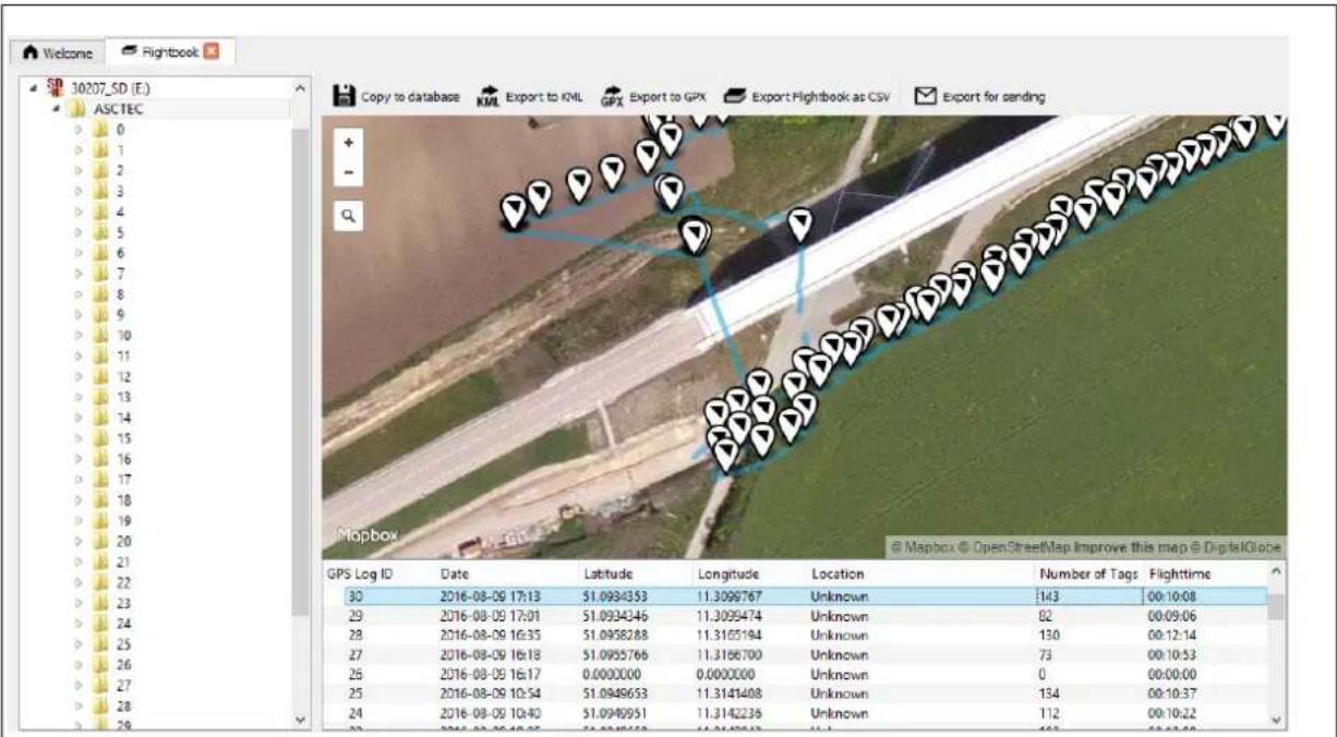
The map view shows the flight path and photo trigger positions, the list view underneath the map shows: the log ID (subsequent number), start time and date, the GPS position (WGS84), the number of image tags (triggers) during the flight, and the flight time. The buttons above the map view allow exporting a single flight as KML or GPX, or an overview of all flights into a CSV file. It is also possible to export a log file as a ZIP file to be able to send it by email.
Please see the chapter 5. Flightbook in the AscTec Navigator Software Manual for further details. The manual can be found here: http://intel.com/FalconManual.
Using the Photo Tagger module in AscTec Navigator, it is possible to geo-reference the images that were taken in-flight. Please see the AscTec Navigator Software Manual for further details.
In the near future AscTec Navigator Software will be replaced by the advanced flight planning software Intel Mission Control. For up to date information, please check:
http://www.intel.com/IntelMissionControl
It might happen that the Intel® Falcon™ 8+ UAV cannot access a logging storage device. Usually, it is caused by a mechanical connection issue or a corrupted file system on the storage device. If the Intel® Falcon™ 8+ UAV cannot access a storage device, a respective warning will be displayed (see following).
Table 2.14: Possible Warning
| CAUSE VISUAL SIGNAL POSSIBLE FIX | |
| User SD card cannot be accessed. | <- Check Msg appears in the status line of the Status Display. Push the related arrow LEFT button on the Intel® Cockpit Controller (CTR) until the Error Message Screen is shown.No user SD card will be shown. |
Take out the User SD card, make a backup copy and format it (file system: FAT32, allocation unit size: 32 kilobytes). After reinserting the SD card into the Intel® FalconTM 8+ UAV, it should again be accessible.If no backup copy is needed, the User SD card can also be formatted directly by the UAV. To do so:1. Push ENT to open the menu on the Status Display.2. Push the arrow RIGHT button to navigate to Settings.3. Push ENT and use the arrow RIGHT button to navigate to Format User SD.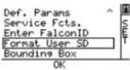 4. Push ENT to confirm.The shown screen appears: 4. Push ENT to confirm.The shown screen appears: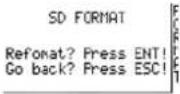 5. Push ENT to confirm the formatting of the User SD card.The process starts, a progress bar is shown.Pushing ESC cancels the function and brings you back to the Main Screen.When the formatting of the SD card is finished, the Intel® FalconTM 8+ UAV will immediately create a new log file and start logging again. 5. Push ENT to confirm the formatting of the User SD card.The process starts, a progress bar is shown.Pushing ESC cancels the function and brings you back to the Main Screen.When the formatting of the SD card is finished, the Intel® FalconTM 8+ UAV will immediately create a new log file and start logging again. |
Table 2.14: Possible Warning (continued)
| Internal SD card cannot be accessed. | <- Check Msg appears in the status line of the Status Display. Push the related arrow LEFT button on the CTR until the Error Message Screen is shown. No internal SD card will be shown. | Switch OFF the Intel® FalconTM 8+ UAV. Wait 10 seconds and switch it ON again. During boot up, the internal SD card will be formatted and it should again be accessible. If this does not help, contact the Intel support team to get instructions on how to proceed. |
| Note | The Intel® FalconTM 8+ UAV can fly without any active logging device. It is the responsibility of the user to make sure that all flights can be properly logged if it is a legal requirement in the country where the system is used. |
The User SD card will not be deleted or formatted by the flight system. We recommend to regularly make backup copies of these storage devices and reformat them afterwards. Especially when working on complex projects, during which the logs are needed for geo-referencing, it is helpful to start with clean storage media.
In this chapter, you will find a description how to operate the Intel® Falcon™ 8+ UAS.
3.1. PREPARING THE INTEL® FALCON™ 8+ UAV
The following section shows and describes how to prepare the Intel ^® Falcon ^™ 8+ UAV for flight.
When using the Intel ^® Falcon ^™ 8+ system for the first time, some additional steps are required, which only need to be performed once. It might be necessary to repeat them only in rare exceptions. In detail, these steps are:
- Establish the initial connection between Intel® Falcon™ 8+ UAV and Intel® Cockpit Controller (CTR) (see “Establishing a connection between the CTR and the UAV” on page 212).
- Set the system date and time on the touchscreen tablet of the CTR (see "THE TOUCHSCREEN TABLET" on page 99).
- Perform a payload and compass calibration with every new payload (see "Payload and compass calibration" on page 36).
- Visit https://intel.com/FalconDownloads and install the latest firmware on the system (see "Intel® Falcon™ 8+ UAS firmware updates" on page 193). Regularly check the website for updates.
Always strictly follow the instructions in "PRE-FLIGHT CHECK" on page 13 to make sure that the UAV is in perfect condition and setup for flight.
Figure 3.1: Preparing the UAV
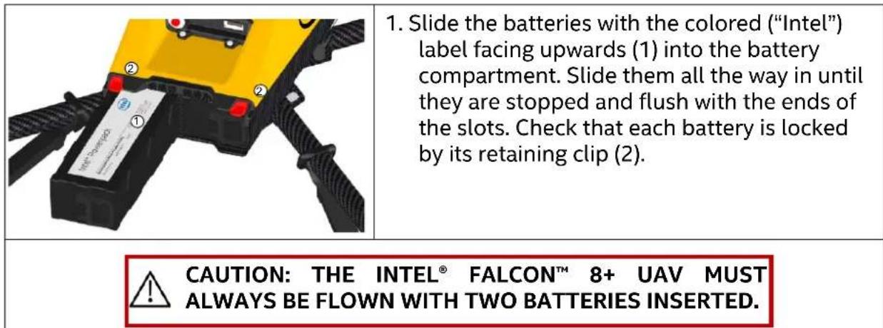
Figure 3.1: Preparing the UAV (continued)
| FE 2,8/35 JNOS | 2. Switch on the camera and remove the lens cap. The image shows the Sony Alpha 7R as an example. Please note that the ON/OFF switch on each payload is different. |
| 3. Press the power button (1) for approximately 2 seconds until you hear a short beep. After approximately 3 seconds the LEDs on both sides of the Intel® Falcon™ 8+ UAV will be lit and you will hear the internal fan running. The UAV is initialized when the camera mount (gimbal) starts to automatically correct movements of the UAV, which also can be heard. It requires approximately 15 seconds to completely power the UAV ON, and is indicated by a triple beep from the Intel® Falcon™ 8+ UAV. The UAS is ready for take-off as soon as the initialization has successfully finished and the link to the CTR has been established. The AscTec Trinity Control Unit allows you to start the UAV even from a moving platform, for example a boat. | |
| Hot swapping batteries To save time it is possible to hot swap batteries while the UAV remains switched ON. 1. Land the UAV. 2. Switch OFF the motors and leave the UAV switched ON. 3. Take out one empty battery, the remaining battery will keep the UAV powered ON. 4. Insert a full battery into the free battery slot of the UAV. 5. Take out the other empty battery. 6. Insert a full battery into the free battery slot of the UAV. 7. Switch ON the motors and continue the mission. When following this procedure, and as long as the UAV remains switched ON, one continuous log file will be created. A new log file will be created only when switching the UAV OFF and ON again. If images need to be geo-referenced, it will be helpful to keep track of the images which belong to each new log file that is created. | |
3.2. PREPARING THE INTEL® COCKPIT CONTROLLER (CTR)
The following section describes how to prepare the CTR.
Figure 3.2: Preparing the CTR
| ① | 1. Open the lid of the battery compartment (1). It is located at the bottom of the lower left-hand side of the CTR. The flap of the compartment is equipped with a magnetic closure. The Intel® Powerpack Battery provides power to the CTR as well as the touchscreen tablet. |
| ① | 2. Slide the battery with the colored "Intel" label (1) facing downwards into the battery compartment. Slide it all the way in until it is stopped and flush with the end of the slot. The Intel® Powerpack battery provides power to the CTR as well as the touchscreen tablet (the battery is the same for the Intel® Falcon™ 8+; see "THE INTEL® POWERPACK BATTERIES" on page 71) |
| 3. Install the shoulder harness by connecting the carabiners of the harness to the first eyelet of the integrated holder (red circle in this image) on each side of the CTR. | |
| ① | 4. Switch on the touchscreen tablet by pushing the power button (1) on the top edge, right side for approximately 2 seconds until a short vibration is felt.5. Unfold the antenna panel on the backside of the touchscreen tablet. The antenna panel must always be pointed at the UAV to ensure best possible transmission quality. |
| 6. Switch on the CTR by pushing and holding the POWER button for a few seconds until a short vibration is felt. |
WARNING DO NOT POWER ON OR OPERATE THE CTR WITHOUT FULLY EXTENDING THE ANTENNA PANEL

CAUTION: WHEN SWITCHING ON THE CTR, THE CENTER POSITION OF THE TWO CONTROL STICKS IS CALIBRATED. MAKE SURE TO NOT MOVE THEM WHILE THE CTR IS POWERING UP. OTHERWISE THERE WILL BE AN ERROR MESSAGE "JOYSTICK ERROR" IN THE STATUS DISPLAY AND IN THE NOTIFICATION AREA OF THE TOUCHSCREEN TABLET AND THE MOTORS CANNOT BE STARTED. IF THIS OCCURS, SWITCH OFF THE CTR AND SWITCH IT ON AGAIN WITHOUT TOUCHING THE CONTROL STICKS.
The Intel® based Windows® touchscreen tablet is directly mounted on the remote control unit of the Intel® Cockpit Controller (CTR) and cannot be removed. It serves as video monitor, displays general flight information and telemetry data, and allows the user to activate automated functions. The battery of the CTR provides power to the touchscreen tablet as well.
To switch the touchscreen tablet ON or OFF, you must push the button located at the top edge of the touchscreen tablet on the right side of the frame for a few seconds (see "Preparing the CTR" on page 97).
After switching the touchscreen tablet ON, you will initially see the blue welcome screen, which, after a few seconds, will change to display the Preflight Checklist where the most important safety aspects are listed.
When starting the touchscreen tablet for the first time, before the Preflight Checklist you will see the window for time and date settings (see following figure).
Figure 3.3: The Cockpit Control Application
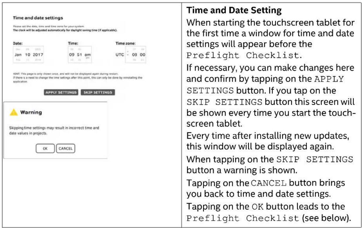
Figure 3.3: The Cockpit Control Application (continued)
| Preflight Checklist✓ Check Permissions- Do you have all needed permits to operate the system at the current site?- Do you have enough training/experience to operate the UAV in all flight modes?✓ Check UAV- Are there no visible defects or loose parts on transport case, UAV or cockpit?- Are the propellers in good condition/firmly mounted/moving easily?- Do all of the motors run correctly?- Is the thumbscrew of the gimba correctly attached?✓ Check Environment- Is there at least a distance of 10 m from the starting/landing point to people, animals or obstacles?- Can you overview the complete flight sector from your position?- Does the starting/landing surface allow all propellers to spin freely?- Is the environment free of any potentially explosive particles?- Do the weather conditions allow operating the UAV?OK SKIP | Preflight ChecklistMake sure to comply with all aspects of the Preflight Checklist. Check all 3 topics:Check Permissions, Check UAV and Check Environment, and tap on OK before take-off. You may tap on SKIP, but it is recommended you follow the checklist and tap on OK.After tapping on OK or SKIP, the main screen of the application is opened (see next picture).Now you can:• use the touchscreen as a preview video monitor;• load, modify and save PATH projects and the related waypoints (optional);• load and fly AscTec Navigator Software projects. |
Figure 3.3: The Cockpit Control Application (continued)
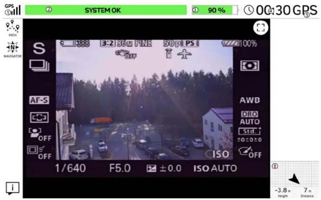
Main Screen
The center of the screen shows the preview video of the mounted payload. All symbols and icons shown here are created by the camera, and do not have any touch functionality. In the above example, the Sony A7R is the payload used. Please refer to "Sony Alpha 7R Full Frame Camera" on page 39, and the Sony camera manual for further information. The Sony camera manual can be accessed online on the Sony support website: https://esupport.sony.com/US/p/model-home.pl?mdl=ILCE7R&LOC=3#/manualstab
In the notification area at the top of this window, general flight information is given. In the left corner under GPS (1), the quality of the GPS signal can be seen, indicated by 1 to 5 bars.
Next to the right of the window, you find the place for system messages (2). If everything is fine, SYSTEM OK is shown in a green bar. In case there are warnings, the field will turn red and display the respective warning. For possible warnings see "Error warnings and messages" below.
Next to the system messages, you find another green bar which indicates the remaining battery capacity of the UAV as a percentage (3) followed by the elapsed flight time (4) and the selected flight mode (GPS) (5).
Figure 3.3: The Cockpit Control Application (continued)
Main Screen (continued)
Tapping on this button, located in the top right corner, displays the preview video in full screen mode (the notification area on top is hidden) and the button changes into the following.
Tapping on this button exits the full screen mode, and the notification area on top is shown again.
In the lower right corner, you find more flight information, which refers to the UAV: Orientation (shown graphically), Height and Distance from the take-off point. Tapping on that flight information field will toggle the view between the video preview and a map view (in case a map has been loaded from an AscTec Navigator project). Learn more about the AscTec Navigator at http://intel.com/FalconManual.
In the near future AscTec Navigator will be replaced by the advanced flight planning software Intel Mission Control. For up to date information, please check:
http://www.intel.com/IntelMissionControl
On the left side of the main screen (under GPS) the buttons for three different functions are found:
Tapping on the PATH button opens the PATH function where you can store and edit individual waypoints and paths (see "PATH Projects" on page 103). This function is an optional part of the Inspection Package (see "SOFTWARE FEATURE PACKAGES" on page 87).
Tapping on the NAVIGATOR button opens the ASCTEC NAVIGATOR PROJECT window, where you can load and fly existing Navigator projects (see "AscTec Navigator Software Projects" on page 111).
☐ Tapping on this button opens a window which gives you information about the currently on the system installed software (versions, available updates, etc.). Tapping on the button again closes the window.
Figure 3.3: The Cockpit Control Application (continued)
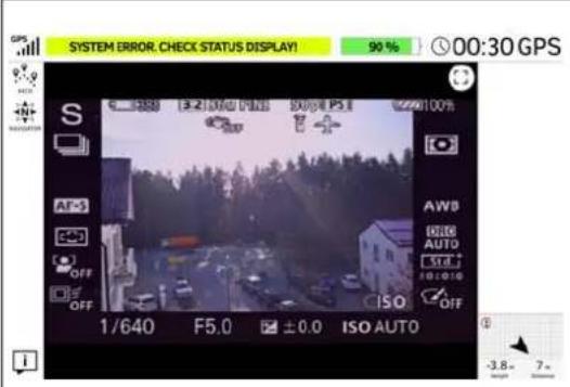
Error Messages and Warnings
If SYSTEM ERROR. CHECK STATUS DISPLAY! is shown in the notification area on top of the touchscreen tablet, you must check the Status Display on the CTR.
If there is only one warning, it will be fully displayed in the notification area.
If more than one warning is present, a popup & drop-down menu is shown.
Tapping the drop-down button will display all warnings. The related text is shown:
- in CAPITALS if an error occurred which has to be checked via the Status Display,
- small letters in the drop-down menu. If the warning is critical and can lead to an imminent crash, the text is shown in a red bar, if it is a warning message it is shown in yellow bar.
The following warnings are only shown on the touchscreen tablet:
Tablet battery weak! = The battery of the touchscreen tablet is low.
Tablet battery empty! = The battery of the touchscreen tablet is empty.
For further details of all possible warnings see "WARNINGS" on page 143
3.3.1. PATH Projects
This function is an optional part of the Inspection Package (see "SOFTWARE FEATURE PACKAGES" on page 87).
With the Cockpit Control application, you can create, load, modify and save PATH projects and any related waypoints. To use this functionality a USB stick (FAT 32 formatted) must be inserted into one of the USB ports, located at the back of the CTR.
It is possible to store and edit individual waypoints (GPS position, height, camera heading, and camera pitch angle) onto a USB stick, which is inserted into the CTR. A waypoint can later be recalled, and the Intel® Falcon™ 8+ UAV will fly to this position and take an image with the stored heading and pitch angle. Camera settings such as shooting mode, or zoom, cannot be stored, and must be set manually before flight. Multiple waypoints can be combined to create a path.
Figure 3.4: The Cockpit Control Application and PATH Projects
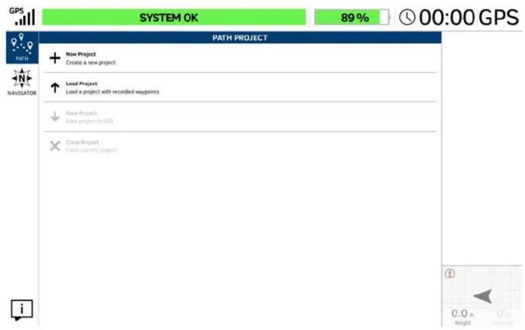
PATH PROJECT
Tapping on the PATH button in the main screen opens the window PATH PROJECT. Here you can create, save, and load individual Paths projects (including the GPS position, height, camera heading, and camera pitch angle).
Executing the PATH function via the touchscreen tablet:
Tapping on New Project opens the window PATH PROJECT - NEW with an integrated keyboard (see below)
Tapping on Load Project opens a window in which you can load an already stored PATH project from a USB stick, which is inserted into the CTR.
Save project: This button becomes active after creating a new, or modifying, a new or existing project. Tap on this button to save the actual PATH project to the inserted USB stick.
Close project: Tap here to close the actual PATH project.
Figure 3.4: The Cockpit Control Application and PATH Projects (continued)
PATH PROJECT - NEW
Preparing and planning a new mission, and generating a new project, is best done before launching the UAV, when you are still on the ground. Tapping on New Project in the PATH PROJECT window (see above) opens the window PATH PROJECT - NEW. In this window, you find a keyboard at the bottom. With the help of this keyboard you may give a name to the new project by tapping on the related keys. Under the Name field the Description field is seen, where you can describe the project in more details.
Tapping on this button hides the keyboard. The keyboard can also be hidden by tapping anywhere in the empty area above. After hiding the keyboard, you first must tap on the button in the lower right corner.
▶ Tapping on this button opens a window with a summary of the data of your new project, and some instructions how to use this function. If you did not already insert a USB stick, you will see a corresponding warning in red. You can now insert the USB stick.
Tap on this button if you want to make changes. You return to the input window, where you can make your changes. If you want to accept the data of your project, tap on the check mark in the lower right corner.
√ Tapping on the check mark saves your new project.
When creating a new project, it is stored in an automatically generated directory
Figure 3.4: The Cockpit Control Application and PATH Projects (continued)
New Project / Record Mode
This functionality allows the pilot to add/generate new waypoints during flight, by using the camera trigger (left control stick S1).
The so named teach-in mode, is activated by using the record button. Waypoints created accidentally can immediately be deleted by tapping the delete button.
The teach-in mode is stopped by tapping on the stop button.
After finishing recording, an automatic flight to all stored waypoints can be executed by using the play icon.
Projects can be saved to the inserted USB stick, and can be reloaded at any time.
After entering the data of your new project, and tapping on the check mark (see above), you can start your new project.
- Launch the UAV.
- Climb to a minimum of 10 m height.
- Tap on the record button to activate the record mode.
- Fly to the first desired waypoint, and make sure the camera points towards the desired spot.
- Push the camera trigger (left control stick S1) to store this and all following desired waypoints in your project.
Waypoints created accidentally can immediately be deleted by tapping the delete button. - To stop recording at the end of your path, tap on the stop button.
- To save your new PATH project tap on the 🎨 PATH button in the upper left corner. This opens the PATH PROJECT window again.
- Tap on the Save Project button. The actual state of your project will be saved on the inserted USB stick.
Figure 3.4: The Cockpit Control Application and PATH Projects (continued)
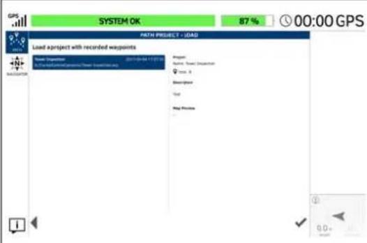
Loading an Existing Project
Tapping on Load Project in the PATH PROJECT window (see above), opens the window PATH PROJECT - LOAD. In this window, you can select/load an already stored project, with recorded waypoints, to be edited and/or flown, from an USB stick.
The USB stick must be inserted at the back of the CTR.
Tapping on the project name, in the left side window, highlights it and shows the related data.
√ Tapping on the check mark, in the lower right corner opens the selected project (see next image).
Tapping on this button in the lower left corner brings you back to the last screen.
In the lower right corner of the window, the UAV is indicated by an arrowhead with its actual orientation, Height and Distance if there is a connection between the UAV and the CTR.
Figure 3.4: The Cockpit Control Application and PATH Projects (continued)
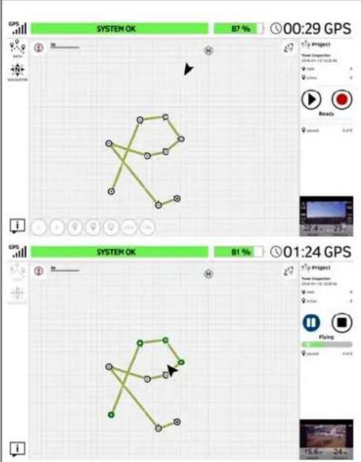
Flying an Existing Project
After loading an existing project, you can fly (and/or modify) the path and the related waypoints.
Tapping on the play button causes the (already launched) UAV to fly the path, and to take pictures at the stored waypoints.
After tapping on the play button, it changes into the pause button as shown below.
Tapping on this button starts the record mode (teach-in mode). Every time you trigger an additional picture, with the left control stick, you generate a new waypoint and any related data is stored (see above).
Tapping on this button zooms your project (all waypoints) back to fit into the window size; e.g. if you zoomed in or out by pinching and/or spreading.
Tapping on this button (only displayed during flight) sets the mission to stand-by.
Tapping on this button stops the mission.
This icon shows the actual home position of the UAV.
Completed waypoints will be marked green in the preview of the touchscreen tablet.

CAUTION: WHEN FLYING A PATH PROJECT, THE UAV FLIES A DIRECT STRAIGHT TRAJECTORY BETWEEN THE WAYPOINTS! KEEP THIS IN MIND WHEN TEACH-IN!
Figure 3.5: The Cockpit Control Application and PATH Projects
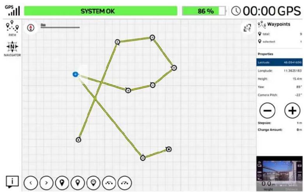
Modifying an Existing Project
As soon as you selected one or more waypoints for modification by tapping on them, the buttons at the bottom, and the related properties on the right side of the screen, are activated accordingly. For easier selection, it is possible to zoom in and out by pinching and spreading the screen. To move the map/project sector drag to alter the view as needed. Tapping anywhere in the map area without selecting a waypoint will de-select all previously selected waypoints.
If only one waypoint is selected, the following described functions can be executed by tapping the related button.
If multiple waypoints are selected, only the "delete", "move to right" and "move to left" buttons are active.
Tapping on this button selects the waypoint next to the actual selected waypoint, against the direction of the teach-in order.
Tapping on this button selects the waypoint next to the actual selected waypoint, in direction of the teach-in order.
Tapping on this button sets the selected waypoint as the new start point.
Tapping on this button sets the selected waypoint as the new end-point.
Tapping on the "delete" button deletes the selected waypoint(s).
Figure 3.5: The Cockpit Control Application and PATH Projects (continued)
Modifying an Existing Project (Continued)
Tapping on the "move to left" button shows the notification "Choose the waypoint to follow the selected waypoints". After tapping on the corresponding waypoint, the direction order of the selected waypoints is changed against the teach-in order.
Tapping on the "move to right" button shows the notification: "Choose the waypoint to precede the selected waypoints". After tapping on the corresponding waypoint, the direction order of the selected waypoints is changed in direction of the teach-in order.
On the right side of the window you see the total and active number of waypoints, contained within the loaded project. After selecting one or more waypoints, the actual selected number of waypoints is displayed.
Under Properties the values of the properties of selected waypoints are shown.
Latitude and Longitude show the related coordinates of selected points.
Height shows the height of selected points.
Yaw shows the heading at which waypoints were stored.
Camera Pitch shows the actual stored pitch angle(s) of the camera.
To change these properties, select the waypoints you want to change to highlight them.
- Tapping on this button once, subtracts the value mentioned at Stepsize.
Tapping on this button once, adds the value mentioned at Stepsize.
The size of a step can be changed by tapping on the number right to Stepsize. This opens a number keypad. With help of the keypad you can enter a new number. The number behind Change Amount shows how often you tapped on the related button (cumulated number of steps).
To change the properties Height, Yaw and Camera Pitch of one or more selected waypoints, you tap on the property you want to change. When its highlighted, tapping on the value of the property opens a number keypad.
With help of the keypad you can enter a new value.
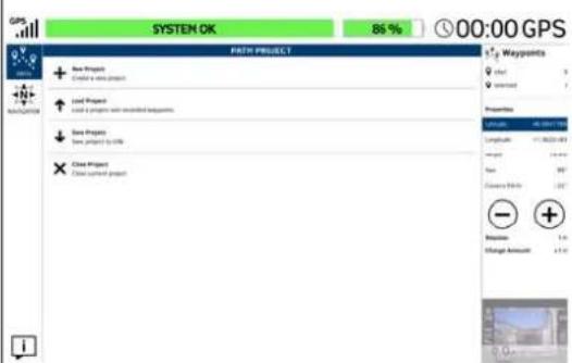
Save PATH Project
After modifying one or more waypoints you can save the modifications by tapping on the PATH button (top left corner). The window PATH PROJECT is opened again (shown to the left). Tapping on Save Project saves the modifications to the project.
3.3.2. AscTec Navigator Software Projects
With the help of the Cockpit Control application you can load and fly survey projects created in the AscTec Navigator Software. To do this, export the existing project from the AscTec Navigator Software by clicking in the AscTec Navigator Software in the Pulldown-Menu File on Export Cockpit project. A file with the extension .ANP will be created, which you must store onto a USB stick. Further information on the AscTec Navigator Software can be found here: http://intel.com/FalconManual.
Insert the USB stick, containing the exported .ANP file, into a USB port of the CTR and tap on the NAVIGATOR button in the main screen of the Cockpit Control application (see "The Cockpit Control Application" on page 99).
Note
AscTec Navigator Software missions can only be executed on the CTR. It is not possible to modify projects. If necessary, please open the project in the AscTec Navigator Software, make the modifications, and then export it to the CTR with help of the USB stick.
In the near future AscTec Navigator Software will be replaced by the advanced flight planning software Intel Mission Control. For up to date information, please check:
http://www.intel.com/IntelMissionControl
Things to consider before flying a survey mission:
- During the complete mission, the pilot must always be able to take over control. Commands given on the CTR will override waypoint flight commands and stop the flight immediately.
- The flight system must always remain within line of sight.
- A good GPS signal needs to be available in the complete area in which the UAV will fly in ( >75% = 4 bars).
- The space in which the Intel® Falcon™ 8+ UAV will be flying, must be free of obstacles.
- Always plan missions with sufficient distance from obstacles and people. There will always be positioning errors of your UAV due to GPS drift and external influences like wind. In addition, the map file may not be absolutely accurate.
- In windy conditions, the UAV may not always fly in a straight line between two waypoints. Plan the mission accordingly.
- Always plan missions with enough height above ground. The UAV may temporarily lose as much as 5 meters of height when flying between waypoints (due to variations in barometric air pressure - drift in sensor values). Due to these variations, it is recommended to plan missions at a height of at least 15 meters above the highest object.
Figure 3.6: The Cockpit Control Application And AscTec Navigator Software Projects
| ASCTEC NAVIGATOR PROJECT Tapping on the NAVIGATOR button in the main screen window of the Cockpit Control application (see "The Cockpit Control Application" on page 99) opens the window ASCTEC NAVIGATOR PROJECT. In this window, you can load an exported AscTec Navigator Software project from an inserted USB stick. | |
| ASCTEC NAVIGATOR PROJECT - LOAD Tapping on Load Project in the ASCTEC NAVIGATOR PROJECT window (see above) opens the window ASCTEC NAVIGATOR PROJECT - LOAD. In this window, you select the desired project by tapping on it. The previously stored waypoint path, and the map view of the AscTec Navigator Software, will be loaded. ✓ Tapping on the check mark in the lower right corner under the Map Preview, transfers the exported project onto the touchscreen tablet. The window with additional flight information, in the lower right corner changes to video preview |
Figure 3.6: The Cockpit Control Application And AscTec Navigator Software Projects
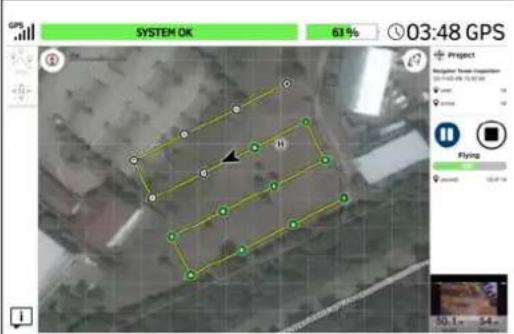
Fly an AscTec Navigator Software Project
After loading an AscTec Navigator Software project you can fly the mission. First you must take-off and climb to a minimum of 10 m height.
After reaching the minimum height, and tapping on the shown play button, the UAV starts the mission and flies to the next waypoint on the path. After tapping on the black play button, it changes into the blue pause button shown below.
After tapping on the play button, during flight, you see the following buttons on the right side:
Tapping on this button sets the mission to stand-by.
Tapping on the stop button stops the mission. The UAV stops and remains at the actual height and position.
For further information on the AscTec Navigator Software, see the AscTec Navigator Software Manual which can be found here: http://intel.com/FalconManual.
Starting and flying an AscTec Navigator Software mission
- When you are ready, take-off and climb to the approximate height and position of the first waypoint.
- Tap on the play button (see before).
WARNING OBJECTS BETWEEN THE STARTING POSITION AND THE FIRST OR INTERMEDIATE WAYPOINT AND OBJECTS BETWEEN WAYPOINTS MUST BE CONSIDERED! THE UAV WILL APPROACH WAYPOINTS OF THE MATRIX IN A STRAIGHT LINE, ASCENDING (OR DESCENDING) CONTINUOUSLY BY ITSELF IF NECESSARY!
- Intel ^® Falcon ^™ 8+ UAV starts to fly the mission.
- Completed waypoints will be marked green on the preview of the touchscreen tablet.
Note
A green waypoint indicates that the Intel ^® Falcon ^™ 8+ UAV successfully passed the waypoint, sent a trigger command to the camera, and a tag was created in the log. It does not necessarily mean that the camera successfully triggered, and stored the image.
-
When all waypoints are done, the UAV will stop at the last waypoint at the actual height.
-
The UAV can now be landed to change batteries, and be prepared for the next mission.
Interrupting a mission
A planned flight may be interrupted at any time, for example to change the batteries during larger survey missions. There are three ways to interrupt a flight manually:
- Tapping on the pause button (see above): the upload of new waypoints will be stopped, and the UAV will stop and hover in the air, until you tap on the (blue) play button again.
- Tapping on the stop button (see above): the upload of new waypoints will be stopped, and the UAV will stop and hover in the air.
• Taking over manually, and giving the UAV a command from the CTR. This will stop the flight of the UAV immediately, as well as the flight mission.
Resuming a mission
If a survey flight was interrupted, it can be resumed at the position where is was interrupted.
If you interrupted the mission by tapping on the pause button, resuming a mission is easily done:
- Launch the UAV up to the minimum height of 10 m.
- Fly close to the waypoint from which the flight shall proceed.
- Tap on the play button.
The UAV resumes the mission automatically by heading for the next waypoint.
If you had to abort a mission by tapping on the stop button, you should note the last waypoint passed when you tapped on the stop button. The number of this waypoint is shown on the right side of the map area on the touchscreen tablet. The number of already passed waypoints in comparison to the total number is shown right to passed: located at the right side of the screen.
To resume the mission, you must:
- Tap on the waypoint (to select it on the touchscreen tablet) from which the flight will proceed.
- Tap on the button to declare the selected waypoint as the new start point.
-
Launch the UAV and climb to a minimum height of 10 m.
-
Make sure that there are no obstacles in the direct trajectory between UAV, and the new start point.
-
Tap on the play button.
The mission will be continued from the waypoint that was selected as the new start point.
3.4. AUTOMATED START-UP CHECKS
Approximately 15 seconds after switching on the UAV a triple beep from the autopilot electronics signalizes the end of the initialization phase.
During the initialization, the system performs an automated start-up check:
- Sensors are checked for functionality.
- Sensor data is checked for plausibility.
• All three flight controller units are checked.
• The "Black Box" (flight logger) SD card is checked.
- The firmware version of the battery is checked (see "Battery Update" on page 77).
• The regional settings regarding the transmission power are checked.
- The current magnetic field is compared with the expected magnetic field.
Irregularities that might affect the flight behavior are reported by a corresponding error notification on the Status Display (for detailed descriptions of possible error messages, see "WARNINGS" on page 143). In case of an error, please try to start the system again at a different location. If the error persists, please contact your local support representative.
3.4.1. Regional Setting
If the Intel® Falcon™ 8+ UAV is switched on in a different region than last time, it will automatically check and if necessary configure all radio parameters to comply with the new region. This is necessary because different regions (e.g. FCC or CE compliant) may have different limits regarding the transmission power. As soon as a valid GPS signal is available this configuration starts. It can take up to 5 minutes. During this process CONFIGURING REGION is shown in the bottom line of the Status Display (see below) and the LEDs of the UAV flash fast. The power button of the UAV is disabled. Please wait until the process is finished and don't interrupt manually.
Figure 3.7: Message shown during Regional Settings
| W16.6V 71% GPS: Cam: 0° Height: 0m Flighttime: 0:00 CONFIGURING REGION | During the procedure of automatic regional settings CONFIGURING REGION is shown in the bottom line of the Status Display. |
3.4.2. Magnetic Field Warning
In flight, the Intel ^® Falcon ^™ 8+ UAV uses algorithms to detect possible disturbances of the compass sensors. If there are discrepancies between the magnetometer output and the expected orientation, the UAV's heading is estimated using the other available IMU (Inertial Measurement Unit) sensors. This technology enhances the robustness of the UAV against external disturbances of the magnetic field.
During start-up, the current magnetic field is compared to the expected magnetic field. If there is a discrepancy, there will be an uninterrupted acoustic signal. The Status Display will display the shown warning.
Figure 3.8: Magnetic Field Warning
| Attention Magnetic Field! Reduced Position Accuracy! On own risk:ENT OK | For a detailed description of this warning and possible solutions, see “Magnetic Field Warning” on page 151. |
3.5. LINK LOSS PROCEDURE
When the UAS has successfully initialized, an appropriate Link Loss Procedure must be selected each time the UAS is switched ON.
The Link Loss Procedure of the Intel® Falcon™ 8+ UAV is automatically activated when there is no data link connection between the Intel® Cockpit Controller (CTR) and the UAV. The UAV has a fully redundant data link, meaning that there are two independent transmitter / receiver connections. If only one of the data link connections is interrupted, the pilot still has complete control over the UAV. The warning LINK WEAK! will be displayed on the Status Display. Only if both links are lost, it will no longer be possible to control the UAV from the CTR. The warning LINK LOST! will be displayed and the Link Loss Procedure is activated. This can occur if the UAV is flown too far from the CTR and/or the antenna panel orientation is not ideal. External influences like shadowing (see “Shadowing” on page 123) or other networks (e.g. WiFi) can also disturb the data link.
There are three different Link Loss Procedures available. One of them must be chosen deliberately each time the UAS is switched on. Every flight may require a different procedure. Therefore, please chose the procedure carefully considering the current mission.
With the RIGHT/LEFT buttons you switch between the three procedures. By pushing ENT, you select the procedure shown on the screen of the Status Display.
Figure 3.9: The Link Loss Procedures
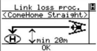 | ComeHome StraightIn case the connection between the CTR and the UAV gets lost (if it is higher than 20 m above the take-off height) the UAV will stop at its current position and fly back to the home position (where the motors were started) at its current height.If the UAV is lower than 20 m at the time the connection is lost, it will first ascend to approximately 20 m above take-off height and then fly back to the home position. Once the UAV has reached the spot above the home position, it will descend at 1.5 m/s until it lands. |
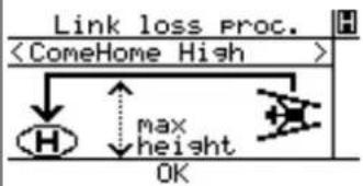 | ComeHome HighIn case the connection between CTR and UAV gets lost, the UAV will stop at its current position and ascend. After arriving at the maximum altitude, that was reached during this flight, it will fly back to the home position and descend with 1.5 m/s until it lands. |
WARNING IF THE BATTERY IS LOW AT THE END OF A FLIGHT, THE EXTRA POWER NEEDED FOR THE ASCENT COULD DEplete THE BATTERY AND LEAD TO A CRITICAL SITUATION.
Figure 3.10: The Link Loss Procedures (Continued)
| Link loss Proc. H <Direct Landing > | Direct Landing In case the connection between CTR and UAV gets lost, the UAV will stop and start a controlled descend at 1.5 m/s at its current position until it lands. If no GPS signal is available, the UAV will always use Direct Landing. Please note that in a situation without GPS signal, the UAV will drift with the wind while descending. |
Home Position
The home position is set automatically each time the motors are started.
Figure 3.11: New Home Position
| Goto Home Navigation Panorama Camera Options Survey Assist OK New Home Position Circle of Interest OK | It is possible to define a new home position while the UAV is in the air. To do so: 1. Push ENT at the Status Display. You enter the shown menu. 2. Push the arrow RIGHT button one time to highlight Navigation. 3. Push ENT. You enter the shown menu. New Home Position is highlighted. 4. Push ENT. The new home position is set at the current location of the UAV at the moment the ENT button is pushed and you return to the Main Screen. |
Please note the following points:
- The flight path back to the home position may not be a straight line, but it may be curved in windy conditions.
- When the UAV is flown in Height-Mode (an H is shown in the upper right corner of the Status Display) or in Manual-Mode (an M is shown in the upper right corner of the Status Display) and the Link Loss Procedure is activated, the UAV will automatically switch to GPS-Mode (a G is shown in the upper right corner of the Status display) if a GPS signal is available.

CAUTION: IN CASE THE LINK LOSS PROCEDURE HAS BEEN ACTIVATED, IT IS RECOMMENDED NOT TO USE MANUAL-MODE. BECAUSE THE UAV WILL AUTOMATICALLY CONTROL THE HEIGHT, USING GPS- OR HEIGHT-MODE, WILL MAKE IT EASIER FOR THE PILOT TO REACT CORRECTLY WHEN THE DATA LINK IS REESTABLISHED AND THE LINK LOSS PROCEDURE IS INTERRUPTED.
- Should the connection between the CTR and the UAV be re-established during the Link Loss Procedure, the UAV will immediately stop the procedure, enter the flight mode selected on the CTR and follow any control input from the pilot.
- If the UAV performed a direct landing because of a lost data link connection, and if you are having difficulties locating it, the last known position of the Intel® Falcon™ 8+ UAV (which is stored in the Status Display of the CTR) might be helpful.
Figure 3.12: Last Known Position
| intel Lat. +48.0952104 Long. +11.3646875 ESC=Back | Push the arrow RIGHT button of the Status Display once (while not connected) and latitude and longitude of last known position will be displayed. |
Situations with varying GPS reception
- If no GPS reception is available, when a data link connection is lost, the Intel® Falcon™ 8+ UAV will use Direct Landing.
- If GPS reception is lost during an active ComeHome procedure, the Intel® Falcon™ 8+ UAV will immediately switch to Direct Landing.
- If no GPS reception is available while the motors are started, the home position cannot be set. If GPS reception becomes available later during the flight, the home position will be set to the location where a valid GPS signal was first received. This home position will be used for the ComeHome procedures. If this does not suit the flight situation, chose Direct Landing.
If the system has landed itself during a Link Loss Procedure, the propellers will continue to turn for 10 seconds when the UAV is already on the ground. After this the motors will be switched OFF automatically.
3.6. FLIGHT MODES
The Intel ^® Falcon ^™ 8+ UAV can be operated in three different flight modes:
Flying in GPS-Mode is easiest as it provides the highest level of automation.
Nevertheless, there will be situations where no GPS signal is available and therefore it is necessary that every pilot is capable to safely control the UAV in Height-Mode. We strongly recommend taking part in an Intel® Falcon™ 8+ UAS operator's training, to learn the basics of flying under qualified supervision. If you are interested in attending a training course, contact your local sales representative.
Figure 3.13: Selecting he flight modes
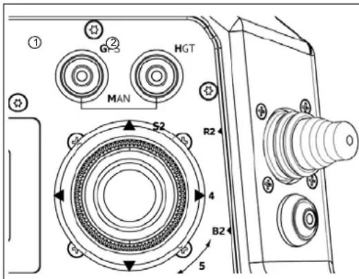
The flight modes can be selected with the two buttons on the upper right corner of the CTR (see "THE INTEL® COCKPIT CONTROLLER (CTR)" on page 23).
- When the button GPS is pushed and is lit, GPS-Mode is active
- When the button HGT is pushed and is lit, Height-Mode is active
- When both buttons are pushed simultaneously and are both lit, Manual-Mode is active For most applications, the Intel® Falcon™ 8+ UAV is best to be flown in GPS-Mode. If necessary, Height-Mode can be conveniently and quickly activated or deactivated with the index finger of the right hand without letting go of the control stick.
When the system is switched on, GPS-Mode will be activated by default. If there is no sufficient GPS reception, Height-Mode will be activated automatically and the Height-Mode button will be lit. In this case, the GPS-Mode button will be flashing to indicate that the system will switch to GPS-Mode as soon as there is a valid GPS signal. In such a situation, it is recommended to actively switch to Height-Mode by pushing the respective button before taking off. This way any unexpected switch of the flight mode can be avoided.
The different flight modes differ in the degree of automation.
Table 3.1: Controlled parameters depending on the flight mode
| GPS BUTTON | HGT BUTTON | ATTITUDE CONTROL | HEIGHT CONTROL | POSITION CONTROL | |
| GPS-Mode ON (lit) OFF √ | √ | √ | |||
| Height-Mode OFF ON (lit) √ | √ | - | |||
| Manual-Mode ON (lit) ON (lit) √ - | - | ||||

CAUTION: THE PILOT MUST BE ABLE TO CONTROL THE UAV NOT ONLY IN GPS-MODE BUT ALSO IN HEIGHT-MODE!
IF THE SYSTEM SEEMS TO BE UNSTABLE OR HAS DIFFICULTIES IN KEEPING ITS CURRENT POSITION IN GPS-MODE, PLEASE IMMEDIATELY ACTIVATE HEIGHT-MODE. BE PREPARED THAT YOU NOW NEED TO CONTROL THE POSITION MANUALLY.
IF THE SYSTEM PERFORMS DRAMATIC CHANGES IN ALTITUDE WITHOUT ANY RELATED COMMAND FROM THE CTR, PLEASE IMMEDIATELY ACTIVATE MANUAL-MODE.
BE PREPARED THAT YOU NOW NEED TO CONTROL THE POSITION AND THE ALTITUDE MANUALLY.
3.6.1. GPS-Mode
Table 3.2: Controlled parameters in GPS-Mode
| HGT BUTTON | GPS BUTTON | ATTITUDE CONTROL | HEIGHT CONTROL | POSITION CONTROL | |
| GPS-Mode OFF | ON | √ | √ | √ |
When there is no input from the pilot, the UAV will:
- Keep its orientation in the air.
- Maintain its position within the limits of the GPS accuracy (approximately 2 – 5 m).
- Keep its height within the limits of the height controller (approximately 1 – 3 m).
• Compensate for wind speeds up to 12 m/s.
For safety reasons and to make operation as easy as possible, there are some limitations:
- Roll and pitch angles are limited to 45^ .
- Speed in horizontal plane is limited to 4.5 m/s.
- Ascend rate is limited to 3 m/s.
- Descend rate is limited to 3 m/s.
In this mode, the inputs via the CTR directly control the speed of the UAV. For example, moving the right control stick completely to the left (which controls pitch and roll) means the system will fly at 4.5 m/s to the left, independent of the wind strength and direction.

CAUTION: WHEN THE GPS QUALITY IS INSUFFICIENT, HEIGHT-MODE WILL AUTOMATICALLY BE ACTIVATED. SHORTLY BEFORE THIS POINT, POSITIONAL ACCURACY MIGHT ALREADY BE TOO LOW AND IT IS STRONGLY RECOMMENDED TO ACTIVELY SWITCH TO HEIGHT-MODE IN SITUATIONS WITH INSUFFICIENT GPS QUALITY.
IF THE SYSTEM AUTOMATICALLY SWITCHES FROM GPS-MODE TO HEIGHT-MODE, THE GPS-MODE BUTTON WILL BE FLASHING, WHILE THE HEIGHT-MODE BUTTON WILL BE LIT PERMANENTLY. THIS INDICATES THAT THE SYSTEM WILL SWITCH BACK TO GPS-MODE AUTOMATICALLY, WHEN A VALID GPS SIGNAL WILL BE RECEIVED.
IF THE SYSTEM SEEMS TO BE UNSTABLE OR HAS DIFFICULTIES TO KEEP ITS CURRENT POSITION IN GPS-MODE, IMMEDIATELY ACTIVATE HEIGHT-MODE. BE PREPARED THAT YOU NOW NEED TO CONTROL THE POSITION MANUALLY ON THE CTR.
Figure 3.14: GPS accuracy
The GPS module of the Intel ^® Falcon ^™ 8+ UAV supports GPS and GLONASS. Under ideal conditions, the horizontal accuracy can reach around +/- 2 m. The short-term accuracy is usually higher, because of the data fusion with other available sensor outputs from the IMU. Vertical accuracy of GPS is lower and the measured altitude can vary up to 15 m depending on satellite constellation. A barometric measurement is used for altitude instead of relying on GPS. Height is always measured above ground level and is reset to zero when the rotors are being started. Throughout the duration of a mission there can be a drift of +/- 5 m due to all possible errors: temperature, drift, weather changes, etc.
Figure 3.14: GPS accuracy (continued)
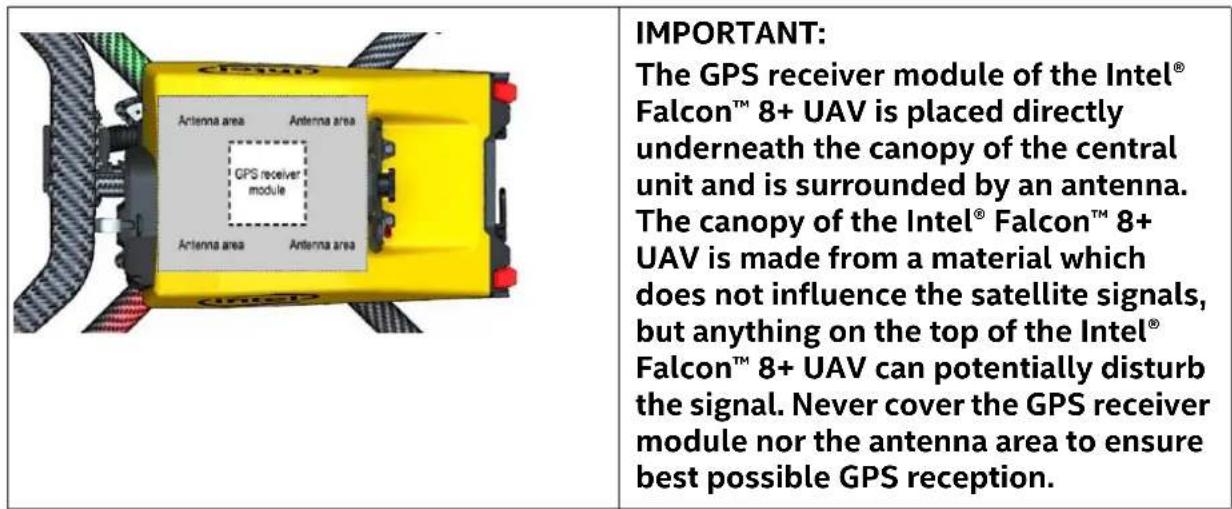
Figure 3.15: Shadowing
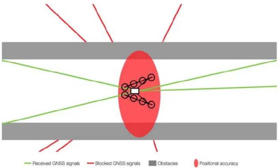
The position accuracy can be impaired when obstacles block the direct line-of-sight from many satellites. The obstacle virtually casts a GNSS-shadow over the concerned area. This results in fewer received satellite signals and a changed geometry of the signals themselves. This effect is very common in urban areas, where satellites can be blocked by tall buildings. You may experience one side of the street has good position accuracy, while on the other side position accuracy is extremely poor. If the UAV moves out of the shadow and more satellite signals can be used to calculate the position, the UAV can suddenly change its position due to the new calculation. Therefore, the pilot needs to pay special attention in such situations. Whenever there are potential shadings of the GPS signal, it is recommended to not use GPS-Mode but to activate Height-Mode on the CTR.
When the Intel® Falcon™ 8+ UAV detects a low GPS quality, it automatically activates Height-Mode and gives the respective GPS lost warning (see “GPS Warning” on page 155). Nevertheless, it is strongly recommended to actively switch to Height-Mode on the CTR beforehand, because it is unpredictable when the system will switch between flight modes. Additionally, the system might only switch to Height-Mode when the positional accuracy is already low for the current flight situation.
Figure 3.16: GPS Multi Path Effects
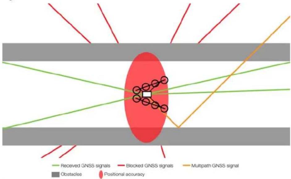
flowchart
graph TD
    A["Received GNSS signals"] --> B["Obstacles"]
    C["Blocked GNSS signals"] --> D["Positional accuracy"]
    E["Multipath GNSS signal"] --> F["Obstacles"]
    G["Received GNSS signals"] --> H["Positional accuracy"]
    I["Blocked GNSS signals"] --> J["Obstacles"]
    K["Multipath GNSS signal"] --> L["Positional accuracy"]
When the UAV is placed close to walls which can reflect the satellite signal, the GPS receiver has no possibility of identifying if the signal comes from a reflection or directly from a satellite. Therefore, there might be situations (often in narrow streets) where reflections are interpreted incorrectly and full GPS reception is displayed, but the actual position accuracy is very low. Therefore, the pilot needs to pay special attention in such situations. Whenever there are potential shadings or reflections of the GPS signal, it is recommended to not use the GPS-Mode.
Compass Error Estimation
In addition to the compass sensors of the Intel ^® Falcon ^™ 8+ UAS, the UAV is equipped with a compass error estimation algorithm.
The compass error estimation uses, among others, GPS-data to estimate the heading of the UAV. For this purpose, horizontal flight movements are necessary. The collected data is used to compensate for potential external disturbances of the compass sensors. Directly after launching it can take the compass error estimator up to 30 seconds to work properly.
The compass error estimator is active only in GPS-Mode. It is not active in Height-Mode and in Manual-Mode. Which means that in case of an external magnetic disturbance, the heading of the UAV might be influenced, resulting in an un-commanded yaw movement of the UAV, which must be compensated for by the pilot.
3.6.2. Height-Mode
Table 3.3: Controlled parameters in Height-Mode
| HGT BUTTON | GPS BUTTON | ATTITUDE CONTROL | HEIGHT CONTROL | POSITION CONTROL | |
| Height-Mode ON OFF √ | √ | - | |||

CAUTION: THE SYSTEM WILL NEITHER KEEP ITS POSITION NOR COMPENSATE FOR WIND. THE POSITION MUST BE HELD MANUALLY BY THE PILOT.
Attitude and height control is active. When there is no input from the pilot, the UAV will only:
- Keep its orientation in the air (system will be leveled).
- Keep its height within the limits of the height controller (approximately 1 – 3 m).
For safety reasons and to make operation as easy as possible, there are some limitations:
- Roll and pitch angles are limited to 50^ .
- Ascend rate is limited to 3 m/s.
• Descend rate is limited to 3 m/s.
WARNING AVOID FULL CONTROL STICK INPUTS IN HEIGHT-MODE! THE UAV CAN BE OVERSTRESSED IN CERTAIN SITUATIONS, SUCH AS FLYING ABRUPT MANEUVERS WITH A LOW BATTERY.
In this mode the inputs, via the CTR, control the roll and pitch angles of the UAV. For example, giving full input to the left (using the right control stick, which controls pitch and roll) means the UAV will roll 50° to the left. With this configuration, the wind direction and speed will influence the direction and speed of the UAV.
3.6.3. Manual-Mode
Table 3.4: Controlled parameters depending on the flight mode
| HGT BUTTON | GPS BUTTON | ATTITUDE CONTROL | HEIGHT CONTROL | POSITION CONTROL | |
| Height-Mode ON √ - | - | ||||

CAUTION: THE UAV WILL NOT KEEP ITS POSITION AND HEIGHT, NOR WILL IT COMPENSATE FOR WIND. CONTROLLING THE POSITION, AND HEIGHT, MUST BE DONE MANUALLY BY THE PILOT FROM THE CTR.
Only attitude control is active. When there is no input from the pilot, the UAV will:
- Keep its orientation in the air (system will be leveled).
For safety reasons and to make it impossible to flip the system:
- Roll and pitch angles are limited to 50^ .
WARNING THE MANUAL-MODE IS FOR EXPERTS ONLY
In this mode the inputs, via the CTR, control the roll and pitch angles and the thrust of the UAV. The direction and the speed of the UAV is influenced by the wind direction and speed.
Having the left control stick in the middle (50%) does not mean the UAV will keep its height. This means the UAV will, depending on the weight of the payload, either ascend or descend when switching from any other mode to Manual-Mode! In most cases with full payload, the system will start to descend. Be prepared to give some thrust to counteract the described effect when switching to Manual-Mode.
3.7. STARTING AND STOPPING THE MOTORS
Figure 3.17: Starting the motors
| To start the motors: 1. Keep the left control stick (S1) in the fully downwards position (1). 2. Use the right hand to push the START/STOP button (2) and hold it for at least one second. The motors will start one after the other, starting with the left motor rail from front to back and continuing with the right motor rail from back to front. If during the starting sequence the left control stick is not kept in the fully downwards position, as a safety measure the starting procedure will be interrupted. All motors, that are already running, will be switched OFF again. Therefore, keep the left control stick down while the motors are starting and do not move it. While the Intel® Falcon™ 8+ UAV is on the ground with running motors, always keep the left control stick, which controls the height, in the fully downward position to avoid any unintentional take-off. Follow the same procedure to switch OFF the motors again. |
3.8. TAKING OFF
A precondition for successful flight missions is a take-off and landing area which is free of obstacles in a radius of at least 10 m, and with free air space, since buildings or trees can block or influence the GPS signal. The propellers need to be able to spin freely (if necessary remove any possible obstacles). The pilot needs to have an unobstructed view of the complete area of operation.
Please keep in mind:
• Always keep a safe distance from people when starting!
- While the Intel® Falcon™ 8+ UAV is on the ground with running motors, always keep the left control stick, which controls the height, in the fully downward position to avoid any unintentional take-off.
- To take off in GPS- or in Height-Mode, move the left control stick from the fully downward position to fully upwards in one, swift movement and ascend to a safe height. In Manual-Mode the ascent rate is much higher. The left control stick must still be moved with one, swift movement, but avoid maximum control stick input.
• In flight, always keep both hands on the control sticks.
3.8.1. Launching in GPS-Mode
Whenever possible, launching in GPS-Mode is recommended. The GPS quality indicated on the Status Display and on the touchscreen tablet must show at least 4 bars.
To launch the Intel ^® Falcon ^™ 8+ UAV in GPS-Mode:
- Push the GPS button on the CTR; it will be illuminated.
- Keep the left control stick completely pulled down (= descend).
- Push the START/STOP button on the CTR up for at least 1 second to start the motors.
- Keep the right control stick centered (no pitch and roll) and push the left control stick completely up (= ascend) to launch the drone.
- Keep ascending until a safe height is reached. Be aware that the Intel® Falcon™ 8+ UAV may drift a little and correction might be required.
- Once the safety height is reached, bring back the left control stick to the center. The Intel® Falcon™ 8+ UAV will then keep its current position, height and orientation as described in "FLIGHT MODES" on page 120.
3.8.2. Launching in Height-Mode

CAUTION: LAUNCHING IN HEIGHT-MODE IS RECOMMENDED FOR EXPERIENCED PILOTS ONLY!
It is necessary to practice this flight mode frequently, because it makes it possible to take off from enclosed areas, areas with magnetic disturbances, or areas with poor GPS reception.
To launch the Intel ^® Falcon ^™ 8+ UAV in Height-Mode
- Push the HGT button on the CTR.
It will be illuminated. -
Keep the left control stick completely pulled down (= descend) while pushing the START/STOP button on the CTR up for at least 1 second.
The motors will start directly. -
Keep the right control stick centered (no pitch and roll) and push the left control stick completely up (=ascend).
The UAV will lift off quickly.
Once in the air you will have to use the right control stick to compensate for the wind (by pitching and rolling the UAV accordingly).
3.8.3. Launching in Manual-Mode

CAUTION: LAUNCHING IN MANUAL-MODE IS FOR EXPERTS ONLY.
In Manual-Mode the pilot must control all axes. There is no automation regulating, nor preventing pilot errors. Normally this mode should not be used.
To launch the Intel ^® Falcon ^™ 8+ UAV in Manual-Mode:
- Push the GPS and HGT buttons on the CTR simultaneously. Both will be illuminated.
- Keep the left control stick completely pulled down (= descend).
-
Push the START/STOP button on the CTR up for at least 1 second to start the motors.
-
Keep the right control stick centered (no pitch and roll) and push the left control stick almost completely up (forward) to launch the drone. The UAV will lift off very quickly. Therefore, be prepared to reduce thrust quickly after a safety distance to the ground is reached. The actual safety distance depends on the specific circumstances of the take-off spot (wind, distance to obstacles, etc.). Be aware that all axes must be controlled manually!
The left control stick is now controlling the motor speed directly, so to ascend you must move the left control stick up with rather strong movements, but very carefully down to descend, because the UAV will automatically descend when there is not enough thrust. Normally you must give at least approximately 50% thrust to maintain your height (depending on the attached payload).
3.9. THE FLIGHT
Figure 3.18: Basic flight principles
| For redundancy, the Intel® Falcon™ 8+ UAV has eight propellers. Four propell- lers turn clockwise, four turn counter- clockwise as shown in the image. This eliminates the torque of the single pro- pellers as much as possible. Nevertheless, the UAV has no inherent stability, and a control circuitry needs to con- stantly monitor and control the UAV to keep it stable. | |
| By varying the turn rate of the different propellers, there are four controllable directions along three axes on which the UAV can be controlled: - Roll axis: movement to the left or right. For example, when rolling to the right, the propellers of the left motor rail are turning faster than the propel- lers on the right motor rail. - Pitch axis: movement forwards or backwards. For example, to fly for- ward, the four back propellers turn faster than the four front propellers. The UAV takes a certain angle along the pitch axis and flies forward. - Yaw axis: adjust the heading of the UAV. When yawing to the left (clock- wise), all left turning propellers turn faster than the right turning propel- lers. - Thrust: ascend or descend along the yaw axis. All propellers turn faster or slower to ascend or to descend. |

CAUTION: DOWNWASH
TRY TO AVOID FLYING THROUGH THE DOWNWASH (TURBULENT AIR UNDER THE UAV CAUSED BY THE PROPELLERS) TO SAVE ENERGY AND TO ENSURE A SMOOTH DESCENT. IT CAN BE AVOIDED BY DESCENDING AND SIMULTANEOUSLY FLYING SIDEWAYS OR BACKWARDS.
3.9.1. Controlling the Intel ^® Falcon ^™ 8+ UAV from the CTR
The standard control mode is called Mode 2. In this mode, the left control stick controls thrust and yaw. The right control stick controls pitch and roll.
The upper part of the right control stick can be turned, which controls the yaw movement of the UAV. This special function makes controlling the UAV very intuitive as all controls to move the UAV in the horizontal pane are accessible with a single hand.
Figure 3.19: Left and right control sticks
Up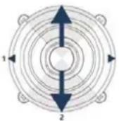 Down Down | Left control stick:thrust & yawThrustUp = ascendDown = descend | Up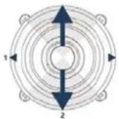 Down Down | Right control stick:pitch & roll & yawPitchUp = fly forwardDown = fly backward |
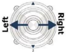 | YawLeft = turn heading leftRight = turn heading right | 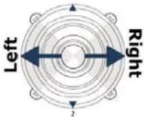 | RollLeft = fly leftRight = fly right |
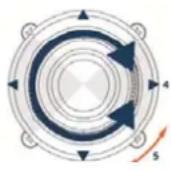 | YawThe upper part of the right control stick can be turned, which controls the yaw movement of the UAV. This special function makes controlling the UAV very intuitive as all controls to move the UAV in the horizontal pane are accessible with one single hand. |
All directional indications are always referring to the point of view of the UAV. Note Depending on the heading of the UAV, directions may be different from the point of view of the pilot.

CAUTION: TO ENSURE SAFE OPERATION ALL PILOTS MUST ALWAYS FOLLOW THE SAFETY GUIDELINES AND THE SAFETY PRECAUTIONS IN "SAFETY FIRST" ON PAGE 7. WE STRONGLY RECOMMEND ATTENDING BASIC TRAINING AND TO FREQUENTLY PRACTICE SESSIONS IN HEIGHT-MODE!
3.9.2. Mission planning
You will maximize flight time when you take your time to plan your missions. Decide on a path and choose position and camera angle before taking-off. Be aware of the size of the area in which you plan to fly. Always ensure the Intel® Falcon™ 8+ UAV has enough battery capacity to fly back to the home position – even if the wind unexpectedly increases.
3.9.3. In-Flight
During the flight, all relevant telemetry information is presented on the Main Screen of the Status Display of the CTR. From top to bottom:
Figure 3.20: Flight information on the Main Screen of the Status Display
| 15.3V 32%GPS: Cam: 0°Height: 0mFlighttime: 0:00OK | From top to bottom:Battery voltage of the UAV: 15.3VRemaining battery capacity of the CTR in percent: 32%Letter G (= GPS-Mode), H (= Height-Mode) or M (= Manual-Mode) indicating the active flight mode0: Counter of triggers sent to the camera. If no trigger has been sent yet, 0 is displayed. Display can vary depending on payload. For further details see “Inspection Payload” on page 43.GPS: GPS quality up to 5 barsCam: Camera tilt level: 0°Height: Current height: 0mFlighttime: starts counting when the motors are startedBottom line OK. If there are any system warnings, the bottom line will display<- Check Msg. Push the arrow LEFT button until the warning message is displayed. More regarding warning messages in “WARNINGS” on page 143. |
Further details regarding the Status Display and its options can be found in “STATUS DISPLAY” on page 166.
3.9.4. General Operating Tips
Please keep in mind: The UAV is not equipped with a sense and avoid system. The operator is responsible for seeing and avoiding all traffic, persons, structures, and obstacles.
We recommend two-person operations (pilot and observer). All sense and avoid is done by the pilot and observer.
Try to avoid situations such as:
• Strong wind or turbulences
• Interference or lost data links
- Weak or shadowed GPS signal ("Shadowing" on page 123)
- Narrow flight areas
• Heights above 1,500 meters above sea level
Figure 3.21: Examples for situations to be avoided
| Turbulences may occur: | Close to buildings or other large objects (e.g. trees, woods).Close to thunderstorms.Above a source of heat (e.g. fire). |
| Interferences that may affect the UAV may occur: | Close to any sources of magnetic or electric fields (e.g. power lines, power generators, antenna poles, large ferromagnetic structures and/or nuclear radiation).Close to strong wireless communication towers like cellular network towers or radar antennas. |
| Urban areas: | The surrounding houses will probably affect the GPS signal. Wind blowing above the houses can cause turbulence, as well as local wind speed spikes due to the wind tunnel effect. In this situation, you can expect sudden movements of the UAV due to the relatively low positional accuracy, and strong external forces from the wind. Extra vigilance is necessary when flying near buildings. |
Good preparation is the key to being able to react correctly in challenging situations.
Perform frequent training sessions, especially in Height-Mode, to become a skilled pilot. Analyze each mission regarding (but not limited to) the above-mentioned factors.
If you find that the Intel ^® Falcon ^™ 8+ UAV does not react to control inputs as expected, for example, inaccurate position control due to bad GPS reception), immediately activate Height-Mode. Keep calm and try to carefully steer the UAV to a spot where less disturbances are to be expected.
3.10. IN-FLIGHT EMERGENCIES
Interruptions to the regular control behavior can be caused by interference sources such as other transmitters near the UAV. They can disturb the video signal (5.8 GHz frequency band), the data link connection (2.4 GHz frequency band) and/or the GNSS module or other system electronics.
In some cases, malfunctions or electronic component failures can also lead to the abnormal behavior of the UAV.
Possible emergencies, and recommended responses, are outlined below.
Table 3.5: Operational guidelines in case of emergency
| EVENT POSSIBLE ACTION | |
| In GPS-Mode: Position accuracy of the UAV is low, and it starts drifting from its current position. | Switch to Height-Mode and control the UAV in Height-Mode.With low GPS reception quality, the UAV might not have automatically switched to Height-Mode yet, and therefore drift from the current position prior to being detected by the sensors is possible. |
| In GPS-Mode: The UAV does not seem to react to the control inputs of the pilot while the data link is not disturbed. | Switch to Height-Mode and control the UAV in Height-Mode.In GPS-Mode, the right control stick on the CTR commands a specific speed. If the speed accuracy is low because of low GPS reception quality (but not yet automatically activated Height-Mode), the reactions to control commands might be slow. |
| In GPS-Mode: The UAV is swiftly flying away from its current position during vertical take-off. | Switch to Height-Mode and continue the vertical take-off to get to a safe distance from the ground and other obstacles quickly. Control the UAV in Height-Mode.The compass sensors might have been disturbed on the ground and the compass error estimation algorithms do not yet have enough information from other sensors to work with sufficient accuracy. After receiving enough input from the IMU sensors, the compass error estimation algorithms are usually able to stabilize the position control even in GPS-Mode."FLIGHT MODES" on page 120 for further information. |
| In GPS- or Height-Mode: The UAV performs strong changes in altitude, which have not been commanded on the CTR. | Switch to Manual-Mode and perform a controlled landing. Get help from support to analyze the cause. Throughout the duration of a mission, there can be a drift of +/- 5 m in altitude due to all cumulative errors: temperature, drift, weather changes, etc. If stronger changes occur, there might be a malfunction of the barometric sensors, which needs to be analyzed.Because of the triple redundant flight control of the Intel® FalconTM 8+ UAV there is a very low probability for this malfunction to occur. |
| Loss of the data link connection between UAV and CTR | Check the antenna orientation.Try to shorten the distance to the UAV by walking towards it.Before take-off:Analyze the flight situation and plan the routes to fly.Based on this assessment, select an appropriate Link Loss Procedure for every single flight.Always make sure that there will be no obstacles in between the UAV and its home position if Link Loss Procedure ComeHome Straight or ComeHome High, has been selected.The Intel® FalconTM 8+ UAS features two fully independent data link connections.In case one link is disturbed, there is always a second independent link on a different channel in the 2.4 GHz band.In case that both data links are lost, the UAV automatically activates one of the three Link Loss Procedures you are forced to select before the start.As soon as the link is re-established you can take control again, and continue the flight.All Link Loss Procedures always go into a controlled descend. |
| Simultaneous loss of GPS reception, and data link connection, between UAV and CTR | Check the antenna orientation.Try to shorten the distance to the UAV by walking towards it.The Intel® FalconTM 8+ UAV will activate the Link Loss Procedure because of the lost data link connection.As no GPS signal can be received, it is impossible to locate the home position and a Direct Landing will be performed. The UAV will drift with the wind in such a situation. |
| A motor stops working in flight. | Steer the UAV with careful control commands and avoid strong control stick inputs.Carefully land the system.Identify and repair the cause of the failure before flying again.Should one of the motors become defective, it will be identified by the UAV and compensated for. A visual, and an acoustical warning signal are given and emitted from the CTR. With the notification, all you must do is bring the UAV back and land in a safe spot. |
| More than one motor stops working in flight | If possible, immediately land the system at its current location with careful control commands avoiding strong control stick inputs. Identify and repair the cause of the failure before flying again.If two or more motors are lost, depending on their position, stable flight characteristics can no longer be guaranteed.When sufficient thrust is missing, the system has the following priorities:AttitudePositionAltitudeMeaning that if insufficient thrust is available, the system will first descend. If still not enough thrust is available, it will start drifting but still try to hold the attitude. Only if physically impossible, the attitude of the system will also be compromised. |
| Gusts of wind above the drone limits / too much wind | In GPS-Mode the Intel® FalconTM 8+ UAV can fly in wind speeds up to 12 m/s. If GPS-Mode is active and there are gusts exceeding 12 m/s you must:1. Switch to Height-Mode.In this mode, the UAV can fly in wind speeds up to 16 m/s.2. Descend to a lower altitude, as wind speed usually decreases at lower altitudes.3. If you are in Height-Mode and wind speed exceeds 16 m/s, descend and if the wind is still too strong, land the system. |
| Loss of information on the Status Display of the CTR | As long as the flight characteristics of the UAV remain unchanged, fly back, land, and analyze the cause of the display failure.If flight characteristics changed regarding position or altitude control, consider changing to Height-Mode or Manual-Mode. |
| The UAV catches fire during start up on the ground | Keep the left control stick down and immediately push the START/STOP button again too switch off the motors. Extinguish the fire. Wait until the UAV has cooled down. Follow the post-flight checklist to store the UAS. Contact Intel support to get assistance in determining the cause. |
| The UAV catches fire in flight | Land the UAV immediately on a safe landing area.Push the START/STOP button to turn off the motors.Extinguish the fire. Wait until the UAV has cooled down. Follow the post-flight checklist to store the UAS. Contact Intel support to get assistance in determining the cause. |
| The UAV flies outside (later-ally or vertically) of the space previously dedicated for the flight. | Action 1 (before take-off)Before you take off you can assure the UAV will stay in the allocated space. You can limit the maximum distance and height of the airspace the Intel Falcon 8+ UAV is flying in by setting specific values which will not be exceeded by the UAV. The center of this bounding box is set to the position of the UAV where Bounding Box is activated.To set these boundaries from the Main Screen of the Status Display (see “STATUS DISPLAY” on page 166):1.Push ENT in the Main Screen.The menu is opened2. Use the arrow RIGHT/LEFT buttons to select Settings.3.Push ENT.The Settings menu is opened.4. Use the arrow RIGHT/LEFT buttons to select Bounding Box.5.Push ENT.The respective menu is opened. Radius is highlighted.6.Push ENT.The field behind Radius is highlighted.7. Use the arrow RIGHT/LEFT buttons to determine the radius the UAV should fly in.The radius can be set from 10 m to 1000 m.8.Push ENT.The value is stored. Radius is highlighted.9.Push the arrow RIGHT button one time to select Height.10.Push ENT.The field behind Height is highlighted.11.Use the arrow RIGHT/LEFT buttons to determine the height the UAV should not exceed.The height can be set from 10 m to 300 m.12.Push ENT.The value is stored. Height is highlighted.13.Push the arrowRIGHTbutton one time to select Activate.14.PushENT.The boundaries are activated. You return to the Main Screen.Action 2Stay calm and fly back into the operating area. If necessary switch to Height-Mode or Manual-Mode (see “FLIGHT MODES” on page 120).Action 3Try to activate the RETURN TO HOME function from the CTR to bring the Intel Falcon 8+ UAV back to where it took off by pushing the dedicated button on the CTR (see “Intel® Cockpit Controller (CTR) Overview” on page 24).Action 4Switch off the CTR to activate the Link Loss Procedure.Before take-off you are forced to choose one of three Link Loss Procedures to determine the automatic landing in the unlikely event that both data links are lost: Direct landing, ComeHome Straight (minimum 20 m altitude or at its current height if higher than 20 m) or ComeHome High (at max. mission height).For more information about the Link Loss Procedure see “LINK LOSS PROCEDURE” on page 116).Action 5Force an intentional crash at an uncritical position. All propellers will stop and the Intel Falcon 8+ UAV will fall down.To do so:1. Switch to Manual-Mode.2. Give full thrust down and simultaneously3. Push the dedicated engine START/STOP button on the CTR for about one second. |
3.11. LANDING
It is recommended to use a wide-open space as a landing spot (approximately 10 m radius around the starting position should be free of obstacles).

CAUTION: BEFORE LANDING THE INTEL® FALCON™ 8+ UAV, ALWAYS ADJUST THE CAMERA TO A HORIZONTAL POSITION TO AVOID DAMAGING THE LENS ON THE GROUND.
Landing in GPS-Mode is recommended. The GPS quality indicated on the Status Display and the touchscreen tablet must show at least 4 bars.
- Activate the GPS-Mode.
- Fly the UAV to a position above the desired landing area at a safe height of at least 3 meters.
- Descend slowly to a height of 1.5 meters and wait until the UAV is stabilized.
- Keep the right control stick centered, while carefully moving the left control stick about half way down to descend slowly.
- Right before touch-down – at 0.2 - 0.3 m – move the left control stick down gradually until the UAV lands on the ground. While the Intel ^® Falcon ^™ 8+ UAV is on the ground with running motors, always keep the left control stick in the fully downward position to avoid any unintentional take-off.
- Keep the left control stick in the fully downwards position and use the right hand to simultaneously press the START/STOP button on the CTR for at least one second to stop the motors.
- Follow the post-flight check ("POST-FLIGHT CHECK" on page 16) to safely switch off and store away the complete system.
- Activate the Height-Mode.
- Fly the UAV to a position above the desired landing area at a safe height of at least 3 meters.
-
Descend slowly to a height of 1.5 meters and wait until the UAV is stabilized.
-
Use the right control stick to maintain the current position as precisely as possible, while carefully moving down the left control stick to descend slowly.
- Right before touch-down – at a height of 0.2 - 0.3 m – move the left control stick down gradually until the UAV lands on the ground. While the Intel® Falcon™ 8+ UAV is on the ground with running motors, always keep the left control stick in the fully downward position to avoid any unintentional take-off.
- Keep the left control stick in the fully downwards position, and use the right hand to simultaneously press the START/STOP button on the CTR for at least one second to stop the motors.
- Follow the post-flight check ("POST-FLIGHT CHECK" on page 16) to safely switch off and store away the complete system.
3.11.3. Landing in Manual-Mode

CAUTION: LANDING IN MANUAL-MODE IS FOR EXPERTS ONLY.
In Manual-Mode the pilot must control all axes directly as there is no automation assisting control, nor preventing pilot errors.
- Activate the Manual-Mode.
- Fly the UAV to a position above the desired landing area at a safe height of at least 3 meters.
- Descend slowly to a height of 1.5 meters and wait until the UAV is stabilized.
- Use the right control stick to maintain the current position as precisely as possible, while carefully moving down the left control stick to descend slowly.
- Right before touch-down – at a height of 0.2 - 0.3 m – move the left control stick down gradually until the UAV lands on the ground. While the Intel® Falcon™ 8+ UAV is on the ground with running motors, always keep the left control stick in the fully downward position to avoid any unintentional take-off.
- Keep the left control stick in the fully downwards position, and use the right hand to simultaneously press the START/STOP button on the CTR for at least one second to stop the motors.
- Follow the post-flight check ("POST-FLIGHT CHECK" on page 16) to safely switch off and store away the complete system.
3.11.4. Switching OFF the UAS
Always switch OFF the UAS in the following order:
-
Camera (wait at least 10 seconds until it has stored all data and is fully powered down).
-
Intel® Falcon™ 8+ UAV:
- Push and hold the power button. The LED position lights will increase brightness. The LED position lights will decrease brightness and simultaneously there will be a short beep from the UAV.
- Let go of the button.
- CTR:
- Push and hold the power button of the touchscreen tablet for approximately 3 seconds until "Slide to shut down your PC" is shown.
- Follow this instruction to fully power down the touchscreen tablet.
- Push and hold the POWER button of the CTR. The CTR will vibrate briefly.
- Let go of the button.
3.12. WARNINGS
The Intel® Falcon™ 8+ UAS displays all warnings which might occur, in the bottom line of the Status Display and in the notification area at the top of the touchscreen tablet. When there is no warning to display, the bottom line of the Status Display shows OK. On the tablet SYSTEM OK is shown in the notification area.
Additionally some of the warnings are announced acoustically by voice over a small integrated loudspeaker.
This loudspeaker is connected to a headphone port (mini jack), which is located on the upper left-hand side of the CTR (see “Intel® Cockpit Controller (CTR) Overview” on page 24). It is possible to connect headphones there, which might be helpful to hear the announced warnings under noisy conditions.
Table 3.6: Possible Warnings
| SHOWN TEXT REASON SIGNALS / NOTES | ||
| Status Display: BATTERY WEAK! Tablet: Falcon battery weak. Land soon! | The battery of the UAV is weak. | Vibration on the CTR Acoustic: “Battery weak. Land soon!” repeated every 20 seconds. Visual: The voltage display of the UAV on the Status Display flashes. |
| Status Display: BATTERY EMPTY! Tablet: Falcon battery empty. Land now! | The battery of the UAV is empty. | Vibration on the CTR Acoustic: “Battery empty. Land now!” repeated every 10 seconds if only one minute of flight time remains. Visual: The voltage display of the UAV on the Status Display flashes. |
| Status Display: CP. BAT. WEAK! Tablet: Cockpit battery weak. Land soon! | The battery of the CTR is weak. | Vibration on the CTR Acoustic: “Battery weak. Land soon!” Visual: The remaining operating time of the CTR shown as a percentage on the Status Display flashes. |
| Status Display: CP BAT. EMPTY! Tablet: Cockpit battery empty. Land now! | The battery of the CTR is empty. | Vibration on the CTR Acoustic: “Battery empty. Land now!” Visual: The remaining operating time of the CTR shown as a percentage on the Status Display flashes. |
| Status Display: BATTERY OVERHEAT! Tablet: Falcon battery temperature high! | The temperatures of the UAV batteries are outside the allowable range | Vibration on the CTR |
| Status Display:NO BATTERY REDUNDANCYTablet: No battery redundancy! | Only one instead of two batteries is detected in the UAV. | This warning occurs only if the motors are turned ON.See as well “Battery warnings of the UAV” on page 149 |
| Status Display:LINK WEAK!Tablet: Link weak! | One of the two data link connections has failed. | Vibration on the CTR Acoustic: “Link weak!” |
| Status Display:LINK LOST!Tablet: Link lost! | Data link connection is lost. | Vibration on the CTR Acoustic: “Link lost!” |
| Status Display:GPS LOST!Tablet: GPS signal lost! | The GPS signal quality is not sufficient. | Vibration on the CTR Acoustic: “GPS lost!” |
| Status Display:MOTOR FAILURE!Tablet: Motor failure.Land now! | There is an error with a motor, a motor controller or the motor bus. | Vibration on the CTR Acoustic: “Motor failure.Land now!” |
| Status Display:JOYSTICK ERROR!Tablet: Joystick error. Land now! | The calibration of the control sticks failed, e.g. because the user was pushing a joystick during turn-on or because something is actually broken. | Vibration on the CTR When the CTR is switched ON, the joysticks are calibrated automatically.Restart the CTR (take care not to exert pressure on any joystick) and see if the warning is still active. If so, the joystick electronics may be broken. In this case please get in touch with Intel support. |
| Status Display:CP.TEMP. HIGH!Tablet:Cockpit temperature high! | The Cockpit tempera-ture is outside of the allowed range. | Vibration on the CTR Check if something is blocking the fan's air stream and if the fan is working properly. Turn OFF the CTR to let it cool down and switch it ON again. If the problem persists, please get in touch with Intel support. |
| Status Display:<- Check MsgTablet: SYSTEM ERROR!CHECK STATUS DISPLAY! | A Trinity system warn-ing is displayed on the Error Message Screen of the Status Display. | See as well “STATUS DIS-PLAY OVERVIEW” on page 166 |
| The following messages are only shown if an Intel® Imaging Payload is mounted (see “Intel® Imaging Payload” on page 54). | ||
| Status Display: OBSTACLE AVOID. N/A!Tablet: Obstacle Avoidance not available! | The Intel RealSense modules cannot be accessed and Obstacle Avoidance is no more available. | Vibration on the CTR |
| Switched to Distance Guard! | The Intel Falcon 8+ has automatically switched from GPS-Mode to Height-Mode (due to insufficient GPS quality) and Obstacle Avoid-ance now works in Dis-tance Guard mode. | Shown only on tablet |
| Camera error! | Camera hardware fail-ure (payload reboot needed). If this does not resolve the issue, please get in touch with the support. | Shown only on tablet |
| Camera lens not recognized! | Lens not recognized (need to remove and re-attach lens, or clean lens contacts). | Shown only on tablet |
| Camera SD card missing! | No SD card in payload (card not inserted or not properly inserted) | Shown only on tablet |
| Camera SD card error! | The camera SD card cannot be accessed. Reasons could be, but are not limited to:• Write protect is enabled on SD card• Wrongly formatted SD card | Shown only on tablet |
| Camera SD card full! | Insufficient space on the camera SD card (SD card is full). | Shown only on tablet |
| Preparing Camera SD card | SD card preparation in progress (camera is building a database onto the card, not ready yet for storing images/videos). | Shown only on tablet |
| Camera temperature high! | Camera high temperature warning (camera is getting too hot, might shut down soon). | Shown only on tablet |
| Payload SD card missing! | No SD card in the pay-load (card not inserted or not properly inserted). | Shown only on tablet |
| The following message is only shown if an Intel® High Resolution Imaging Payload is mounted (see “Intel® High Resolution Imaging Payload” on page 48). | ||
| Status Display:Pay1. GPS not ready | The Intel® High Resolution Imaging Payload does not receive a sufficient GPS signal. | Possible workaround:Wait several minutes. It might take some time until the GPS receiver of the payload has synchronized.Move to a location with better GPS reception.Power the UAV OFF and then ON again. |
| The following messages are only shown in the notification area on the touchscreen tablet. | ||
| Tablet battery empty! | The battery of the touchscreen tablet is empty. | Shown only on tablet |
| Tablet battery weak! | The battery of the touchscreen tablet is low. | Shown only on tablet |
| Gamepad requires inspection license! | A gamepad for a second camera operator was connected but the feature, which is part of the Inspection Package, is not activated on the UAV (see “THE INDEPENDENT CAMERA CONTROL (ICC)” on page 28. | Shown only on tablet |
3.12.1. Critical Battery Levels & Warnings of the UAS
The following section describes especially the important acoustic and visual warnings (in the bottom line of the Status Display and in the notification area at the top of the touchscreen tablet) that caution you of low or empty batteries of the UAS.
WARNING THE UAV MUST BE LANDED IMMEDIATELY AFTER THESE WARNINGS.
Battery warnings of the UAV
Note
The Intel Falcon 8+ takes many data points into account to calculate the remaining flight time. These include, among others, the current average power consumption, remaining charge of the battery and the potential of one battery being depleted sooner than the other. Due to this, battery warnings may appear sooner than expected or (when suddenly reducing the average power consumption) even disappear again. If in doubt, the pilot can check the battery voltage on the Main Screen of the Status Display. It is advised to prepare the landing procedure at 14.2 V and be on the ground at 14.0 V. Beyond 14.0 V, the system may become unstable.

CAUTION: THE SYSTEM MUST ALWAYS BE LANDED BY THE PILOT! THERE IS NO AUTO-LANDING IN CASE OF LOW OR EMPTY BATTERY.
Table 3.7: Warnings depending on critical battery levels of the UAV
| SIGNALS EXPLANATION | |
| Acoustic: “Battery weak, land soon!”Tactile: Vibration on the CTRText on the Status Display:BATTERY WEAK!Text on the tablet:Falcon battery weak.Land soon!Additionally, the voltage display on the Status Display starts flashing. | Voltage of the UAV:~ <= 14.4 V or the UAVremaining runtime is below 4 Minutes.The audio warning is repeated every 20 seconds. |
| Acoustic: “Battery empty, land now!”Tactile: Vibration on the CTRText on the Status Display: BATTERY EMPTY!Text on the tablet: Falcon battery empty.Land now!Additionally, the voltage display on the Status Display flashes. | Voltage of the UAV:~ <= 14.1 V or the UAV remaining runtime is below 2 minutes. The audio warning is repeated every 10 seconds when the remaining flight time < 1 minute.You must land immediately.The battery and/or UAV can be damaged if the flight is continued. |
| Text on the Status Display:NO BATTERY REDUNDANCYText on the tablet: No battery redundancy! | This warning occurs only if the motors are turned ON.The total flight time will be reduced and no battery redundancy will be available.If the warning occurred in-flight with two batteries inserted, land immediately and look for the reason. Possible reasons could be but are not limited to:One battery was not correctly insertedOne battery has a defective cell. |
Battery warnings of the CTR
The following warnings refer to the CTR battery:
Table 3.8: Warnings depending on critical battery levels of the CTR
| SIGNALS EXPLANATION | |
| Acoustic: “Battery weak, land soon!”Tactile: Vibration on CTRText on the Status Display: CP. BAT. WEAK!Text on the tablet: Cockpit battery weak.Land soon!Additionally, the remaining operating time of the CTR, shown as a percentage on the Status Display starts flashing. | The battery of the CTR is weak.The audio warning is repeated every 20 seconds. |
| Acoustic: “Battery empty, land now!”Tactile: Vibration on CTRText on the Status Display:CP. BAT. EMPTY!Text on the tablet: Cockpit battery empty.Land now!Additionally, the remaining operating time of the CTR shown as a percentage on the Status Display flashes. | The battery of the CTR is empty.The audio warning is repeated every 10 seconds when the remaining operating time < 1 minute.You must land immediately.The battery and/or UAV can be damaged if the flight is continued. |
3.12.2. Magnetic Field Warning
While starting the Intel ^® Falcon ^™ 8+ UAV, a magnetic field warning may occur.
Usually disturbances on the ground come from underground lines and can quickly be resolved by switching off the Intel ^® Falcon ^™ 8+ UAV, moving it to a different spot and starting from the new location.
Alternatively, it is possible to start in Height-Mode to avoid any position corrections by the system which might occur in GPS-Mode, and then only activate GPS once in the air. The magnetic disturbance will then be at a safe distance and the estimation algorithms will be active.

CAUTION: IF THIS WARNING OCCURS, NEVER TAKE OFF FROM THAT SPOT IN GPS-MODE! IT MIGHT LEAD TO UNEXPECTED POSITIONAL CHANGES OF THE UAV.
Table 3.9: Acoustic and visual magnetic field warning
| SIGNALS EXPLANATION | |
| Acoustic:A constant loud beep is heard.Visual on Status Display:Attention Magnetic Field! Reduced Position Accuracy!On own risk:ENTOK | This warning only appears when the system is not yet flying. It means the UAV is close to a magnetic field, which disturbs the correct determination of the UAV's orientation. Thus, starting in GPS-Mode can lead to uncontrolled movement of the UAV in the attempt to hold the exact position.To resolve this warning:1. Switch OFF the Intel® FalconTM 8+ UAV, the touchscreen tablet and the CTR.2. Move the UAV to a different spot and switch the complete system ON again.3. If the warning is no longer present, you can take off in GPS-Mode.If the warning is not resolved or if taking off from a different spot is impossible, you can:1. Switch to Height-Mode and take off in Height-Mode to avoid any position corrections by the system, which might occur in GPS-Mode.2. Fly to open space and keep Height-Mode activated for at least 20 seconds (it will help the estimation algorithms if some movements forward, backward, left and right are performed).3. Switch to GPS-Mode in open space. The magnetic disturbance will then be at a safe distance and the estimation algorithms will be active.4. Always be prepared to switch back to Height-Mode anytime.For more information about the different flight modes see “FLIGHT MODES” on page 120.The warning can be canceled by pushing the ENT button of the Status Display on the Intel® Cockpit Controller (CTR). |
In flight, the Intel ^® Falcon ^™ 8+ UAV uses algorithms to detect possible disturbances of the compass sensors. If there are discrepancies between the magnetometer output and the expected orientation, the UAV's heading is estimated using the other available IMU sensors. This technology enhances the robustness of the UAS against external disturbances of the magnetic field.
Note
Since the IMU sensors, like accelerometers, are needed to estimate the heading, the compass estimation does not work if the UAV is standing still on the ground. During start-up, the current magnetic field is compared to the expected magnetic field. If there is a discrepancy, there will be a warning as described above. The warning can be canceled by pushing the ENT button of the Status Display on the CTR.

CAUTION: IT IS IMPORTANT TO NOTE THAT AS LONG AS THE INTEL® FALCON™ 8+ UAV REMAINS SWITCHED ON, THE CANCELED MAGNETIC FIELD WARNING WILL NOT BE REPEATED.
IF THE INTEL® FALCON™ 8+ UAV IS MOVED TO A DIFFERENT LOCATION WHILE BEING SWITCHED ON, THERE WILL BE NO WARNING, EVEN IF THERE IS A MAGNETIC DISTURBANCE PRESENT.
If this warning occurs, never take off from that spot in GPS-Mode! It might lead to unexpected positional changes of the UAV.
The warning can be canceled by pushing the ENT button of the Status Display on the Intel® Cockpit Controller (CTR).
3.12.3. Data Link Warnings
The following data link warnings may occur in the bottom line of the Status Display.
Table 3.10: Diversity Data Link warnings
| SIGNALS EXPLANATION | |
Acoustic: “Link weak!”Tactile: Vibration on CTRVisual on the Status Display: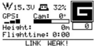 Text on the tablet:Link weak! Text on the tablet:Link weak!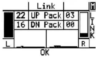 | The Intel® FalconTM 8+ UAV has two fully independent data link connections. In case one link is disturbed, the LINK WEAK message is shown. Nevertheless, the system can still be fully controlled via the second independent link, on a different channel in the 2.4 GHz band.Check if the antenna panel of the CTR is completely unfolded and reduce the distance to the UAV until the signal strengthens.In case of this message pushing the arrowRIGHTbutton of the Status Display three times opens the shown screen with details about the signal strength of both data link connections. |
Acoustic: “Link lost!”Tactile: Vibration on CTRVisual on the Status Display: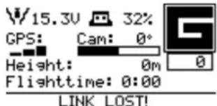 Text on the tablet:Link lost! Text on the tablet:Link lost! | The UAV has flown out of range and there is no data link connection between UAV and CTR anymore. In this case the preselected Link Loss Procedure is automatically activated. |
3.12.4. GPS Warning
The following GPS warning may occur in the bottom line of the Status Display.
Table 3.11: GPS signal warning
| SIGNALS EXPLANATION | |
Acoustic: “GPS lost!”Tactile: Vibration on CTRVisual on the Status Display: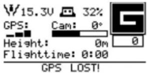 Text on the tablet:GPS signal lost! Text on the tablet:GPS signal lost! | The quality of the GPS signal is not sufficient to reliably keep the position of the UAV. It will automatically switch to Height-Mode.The pilot must always be capable of controlling the UAV in Height-Mode!If the system automatically switches from GPS-Mode to Height-Mode, the GPS-Mode button will be flashing, while the Height-Mode button will be lit permanently. This indicates that the system will switch back to GPS-Mode automatically, when a valid GPS signal will be received. In situations where a loss of the GPS signal can be predicted, it is always better to manually switch to Height-Mode. |
3.12.5. Motor Failure Warning
The following motor failure warning may occur in the bottom line of the Status Display.
Table 3.12: Motor warning (Controller)
| SIGNALS EXPLANATION | |
| Acoustic: “Motor failure, land now!”Tactile: Vibration on CTRText on the Status Display:MOTOR FAILURE!Text on the tablet:Motor failure. Land now! | A motor, motor controller, and/or propeller is not working properly. In most situations, the redundant propulsion system will compensate one failing motor/rotor combination.Land immediately, controlling the UAV with careful, soft maneuvers and try to identify and fix the root cause.In case of this message push once the arrow LEFT button of the Status Display, when the Main Screen is shown. This opens a screen which helps identifying the motor causing the warning. |
3.12.6. AscTec Trinity Control Unit System Warnings
Whenever there is a system warning, (shown as SYSTEM ERROR in the notification area on the touchscreen tablet), the bottom line of the Status Display will show <- Check Msg.
Figure 3.22: System warnings
| W15.3V 32% GPS: Cam: 0° Height: 0m Flighttime: 0:00 <- Check Msg | If<- Check Msg is shown in the status line there is no acoustic warning. In this case push the arrow LEFT button five times (when starting on the Main Screen of the Status Display). |
| N1C:n't fly home - N2C:n't fly home - <- Check Msg | The Error Message Screen (shown on the left) is opened, and the details are presented. |
The table below shows all possible warnings, their meaning, and possibilities for resolving them. All messages always have one of the prefixes N1U / N1C / N2U / N2C, meaning:
• N1 = Navigational processor 1
• N2 = Navigational processor 2
- U = message concerning the user - might be application critical but not flight critical
- C = message concerning the core - flight critical!
Table 3.13: AscTec Trinity Control Unit system warnings
| CATEGORY | WARNING/ERROR | MEANING CONSEQUENCE | E | POSSIBLE FIXES |
| License chip | UUID chip mal-function! | UUID chip not functional (can-not be installed / not programmed / defective). | Serial Number is 31000 (default), no flags can be stored. | Contact support. |
Table 3.13: AscTec Trinity Control Unit system warnings (continued)
| CATEGORY | WARNING/ERROR | MEANING CONSEQUENCE | POSSIBLE FIXES |
| License chip | License chip: too many read errors | UUID chip not functional (can- not be installed / not programmed / defective). | Contact support. |
| License chip | License chip: too many write errors | UUID chip not functional (can- not be installed / not programmed / defective). | Contact support. |
| Parameters | No parameter file found! Restoring default para-meters. | Trinity board fresh from pro- duction. | Restart System. |
| Parameters | Parameter version conflict => auto update done! | New firmware sometimes requires new parameter sets, which are auto-matically written to FLASH mem-ory. | Restart System. |
| Missing feature | SURVEY PACKAGE not installed | The feature needs to be unlocked. | Contact support to acquire miss-ing features. |
| Sensor data cor-rupt - critical! | Position input data corrupt! Position fusion disabled! | Restart system or con-tact support. | |
| Sensor data cor-rupt - critical! | GPS2COGcompen-satedpositiondatacorrupt! | Restart sys-tem or con-tact support. | |
| Sensor data cor-rupt - critical | Magneticincli-nation/decli-nation datacorrupt! | Restart sys-tem or con-tact support. | |
| Sensor data cor-rupt - critical! | Data-fusioninput datacorrupt! | Restart sys-tem or con-tact support. | |
| Sensor data cor-rupt - usually notcritical due to IMUredu-dancy | IMU1/IMU2/IMU3 datacorrupt! | Any sensor value out of range. | Restart sys-tem. |
| SD Card | No internal SD card! | Internal SD card cannot be used (missing, full, file system corrupt). | Insert / refor-mat SD card. |
| SD Card | No user SD card! | SD card in front of central unit faulty (missing, full, file system corrupt). | Insert / refor-mat SD card; use a different SD card. |
| SD Card | FAT Write to Sector 0??? | Error with SD card logger, possibly SD card defective. | SD card logger not working in this flight. |
| Navigation | Waypoint sanity check failed | Waypoint trans-mission problem. | No waypoint navigation. |
| Navigation | Navi-gation data corrupt | Spline calculation problem. | No waypoint navigation. |
| Navigation | Tra-jectomy flight in progress -> CMD ignored! | No reaction to data transmis-sion. | |
| Navigation | Can't fly home - no home position set! | ComeHome does not work. | |
| Navigation | N2U: Trajectory flight in progress -> CMD ignored! | The user tried to execute a survey flight while a pre-viously started survey flight is still ongoing. The command sent to the UAV will be ignored and the current survey flight will be con-tinued. | |
| Calibration | No calib on payload found | Timeout: Not able to read a payload calibration from camera EEPROM within 15 seconds after start-up. Usually happening with new Payloads / Payloads never calibrated on an Intel® FalconTM 8+ UAV. | Possibly bad yaw alignment. Run payload calibration. |
| Calibration | Invalid payload calib - please recalibrate! | Payload calibration invalid. The reason could be that less than 3 IMUs were available during the calibration process. | Possibly bad yaw alignment. Run payload calibration again. |
| Calibration | No payload installed or payload config faulty | Payload could not be found. | Payload not working. Check Pay-load connection; re-initiate camera type EEPROM. |
| Calibration | Payload calibration not successful! | Payload calibration failed. | Possibly bad yaw alignment. Run payload calibration again. If the message is displayed again, contact the support. |
| Calibration | Could not write CC for PayloadID | In-flight compass calibration with specific payload failed. | Run in-flight compass calibration again. If the message is displayed again, contact the support. |
| Calibration | in-flight CC stored to FLASH | The compass calibration was successfully stored. | The compass calibration was successfully stored. |
| Calibration | No c.calib. matching PID, using default. | No in-flight compass calibration found matching the installed payload. | Run in-flight compass calibration. |
| Calibration | No in-flight compass calibration found! | No in-flight compass calibration found at all. | Run in-flight compass calibration. |
| Calibration - critical! | No temperature calibration found! | Contact support. | |
| Calibration - critical! | Acc and/or mag calibration missing! | Contact support. | |
| Calibration - critical! | IMU1/IMU2/ IMU3 MAG calibration problem | Contact support. | |
| Payload communication | Payload EEPROM compromised! | A payload is detected but the information in the eeprom flash is not valid. | It will not be possible to control the payload from the CTR. Annual software feature packages, which are stored on the payload, will not be accessible. Additional payload related warnings might be displayed. |
| Video | Falcon video flash corrupted (A, F, I, M or S) | There is an issue with the video flash. | No video reception. |
| Video | Cockpit video flash corrupted (A, F, I, M or S) | There is an issue with the video flash. | No video reception. Download and install the latest Intel Falcon 8+ UAS firmware. If this does not help, contact the support and provide the exact error message including the letter in brackets. |
| Motors | Motor temperature too high! Land now! | The temperature of one or more motors is too high. | Potential motor failure. Land immediately. Steer the UAV with careful control commands and avoid strong control stick inputs. Carefully land the system. Contact the support and provide log files. |
| Motor bus communication | Not all Motors detected | 1 or more motor controllers have not given a status update. | Communication from at least 1 motor controller has failed. UAV will not start/ take off. Hardware or connection problem, do not fly! Contact support. |
| Motor bus communication | Too many CRC errors on motor bus! Land now! | Communication to the motor controllers is disturbed. | Danger that motors will stop working. |
| Motor bus communication | Motor bus not working! Land now! | Communication loss from all motor controllers. | Communication or complete hardware failure. |
3.13. OPERATIONAL LIMITATIONS
The Intel ^® Falcon ^™ 8+ UAS has the following operational limits:
- Wind speeds up to 16 m/s in Height-Mode respective 12 m/s in GPS-Mode. Above these limits the UAV will not be able to hold its position.
- Intel® Falcon™ 8+ UAV operating temperature: -5 °C and 45 °C (23 °F to 113 °F).
- Intel® Cockpit Controller operating temperature: -5 °C and 45 °C (23 °F to 113 °F).
- Intel® Powerpack battery operating temperature: -5 °C and 40 °C (23 °F to 104 °F).
The operating temperature of the UAS, i.e. the complete system including all components, is currently limited by the operating temperature of the battery. Therefore, the operating temperature of the Intel ^® Falcon ^™ 8+ UAS is -5 °C and 40 °C (23 °F to 104 °F). The upper temperature limit is likely to increase with the introduction of the new battery technology in the future.
Table 3.14: Payload weight
| PAYLOAD ACTIVELY | STABILIZED MOUNT | REMAINING PAYLOAD |
| 800 g ~ 200 g ~ 600 g |
- A maximum distance of 250 meters between the UAV and the pilot is recommended. Beyond this range the UAV becomes too small to see.
- The UAV is not waterproof. Flying in rain, fog or snow is undertaken at your own risk and not recommended.
- Flying in dusty or sandy areas may damage the cameras and motors permanently.
- Altitudes of more than 3,500 meters above sea level are risky. Flight time and stability decrease dramatically.
- Do not take off in areas with strong external magnetic fields if you are not used to flying in Height-Mode.
• Acrobatic flight is prohibited.
4. STATUS DISPLAY
In this chapter, you will find a description of all possible messages and operations using the Status Display.
4.1. STATUS DISPLAY OVERVIEW
The Status Display of the Intel ^® Cockpit Controller (CTR) shows all relevant information for flying.
Figure 4.1: Status Display
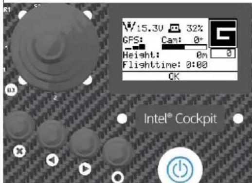
On the Status Display you can view the current settings and adjust specific functions of the UAV. To do so, you use the four buttons.
Escape (left side) is used to leave menus / sub-menus and to clear functions. In the following text, it is displayed as ESC.
With the LEFT arrow button (middle, left side),
and the RIGHT arrow button (middle, right side) you can scroll through menus or alter parameters.
Enter (right side) is used to enter menus and activate functions. In the following text, it's displayed as ENT.
4.1.1. Status Display Menu Structure
For further information in terms of the Status Display see "The Status Display" on page 27.
Table 4.1: Status Display Menu Structure
After switching on the CTR the first screen you see on the Status Display is the Welcome Screen. Falcon Status Display Falcon Status Display | ||||
After some seconds, the screen changes to the Start Screen. Waiting for linkENT=SearchRIGHT=Last Position Waiting for linkENT=SearchRIGHT=Last Position | If the UAV is switched on and there is no connection established to the CTR, you should push ENT. The following screen appears:Falcon Serial:1000OK ESC | For entering the serial number see “Establishing a connection between the CTR and the UAV” on page 212. | By pushing the RIGHT arrow button the latitude and longitude of the last known position of the UAV are shown: Lat.+40.6952104Lon.+11.3646875ESC=Back Lat.+40.6952104Lon.+11.3646875ESC=Back | Pushing ESC on the screen, with last known position, brings you back to the Main Screen. |
When the Falcon F8 is switched on and there is already an established connection with the CTR, after a few seconds the screen changes to the Main Screen.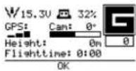 On this screen, you will find the following information: 15.3V: Battery voltage level of the UAV On this screen, you will find the following information: 15.3V: Battery voltage level of the UAV | 32%: Remaining battery capacity of the CTRGPS: GPS signal strength; at least four bars are required for flying in GPS-Mode.Cam: Tilt angle of the camera gimbal. Values vary from approx. -100° to +100° (-90° means the camera is looking vertically downwards). | Height: Barometrically measured height above ground level (0m = where the propellers are started). Flighttime: The flight time counter will start when the propellers are switched on and is updated as soon as one battery is changed.G: Flight mode (G, H, M, see “FLIGHT MODES” on page 120) | 0: Counter of triggers sent to the camera.OK: Status line. Everything is OK with the system. Otherwise there will be the warning <- Check Msg. In this case press the LEFT arrow button 5 times, until the Error Message Screen is shown. see “AscTec Trinity Control Unit System Warnings” on page 156. | |
After a few seconds, the screen changes to Link loss proc.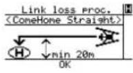 | Here you must select the mode determining how the UAV will behave in case of a lost link. For help selecting the mode, see “LINK LOSS PROCEDURE” on page 116. | After selecting the appropriate Link Loss Procedure by pushing ENT, confirming the screen changes to the Main Screen. | ||
| Pushing the RIGHT/LEFT arrow buttons in the Main Screen leads you to different screens. For more information about these screens see “The Main Information Screens” on page 178. | ||||
Orientation Screen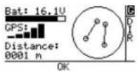 | GPS Info Screen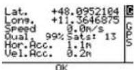 | Data Link Screen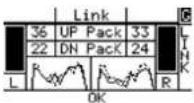 | Attitude Angles Screen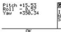 | |
| shows:• Battery status• GPS signal strength• Distance to Home Position• UAVtation• Possible warnings• Flight mode | shows:• Latitude• Longitude• Speed• Reception quality• Horizontal accuracy• Velocity accuracy• Possible Warnings• Flight mode | shows:• Left and right transmitting and receiving packages• Graph• a n a l• Signal quality• Possible warnings• Flight mode | shows:• Pitch Angle• Roll Angle• Yaw Angle• Possible warnings• Flight y z e r mode | |
Flight controller Screen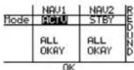 shows:• N A V 1• N A V 2•Warnings• Redundancy• Possible warnings shows:• N A V 1• N A V 2•Warnings• Redundancy• Possible warnings | Error Message Screen(optional)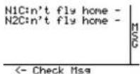 shows:• Possible flight controller (e.g. N1C/N2C)For system warnings see “AscTec Trinity Control Unit System Warnings” on page 156. shows:• Possible flight controller (e.g. N1C/N2C)For system warnings see “AscTec Trinity Control Unit System Warnings” on page 156. | Motor Screen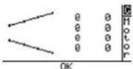 shows:• Graphic of the Intel® FalconTM 8+ UAV with spinning propellers• Speed of each propeller (as a coefficient)• Flight mode shows:• Graphic of the Intel® FalconTM 8+ UAV with spinning propellers• Speed of each propeller (as a coefficient)• Flight mode | Battery Screen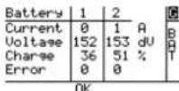 shows for battery 1 and 2:• Actual current in ampere (A)• A c t u tem voltage in decivolt (dV)• C h a r state of each battery in percent• Number of errors shows for battery 1 and 2:• Actual current in ampere (A)• A c t u tem voltage in decivolt (dV)• C h a r state of each battery in percent• Number of errors | BMS Screen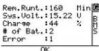 shows:• Remaining runtime of the UAV in minutes• a Al cs ty us voltage• Charge state of the UAV in per-g cent• Number of batteries inserted• Number of errors shows:• Remaining runtime of the UAV in minutes• a Al cs ty us voltage• Charge state of the UAV in per-g cent• Number of batteries inserted• Number of errors |
| Pushing the RIGHT/LEFT arrow buttons in these screens brings you back to the Main Screen. | ||||
Pushing ENT in the Main Screen opens the following screen: 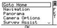 | Pushing ENT when Goto Home is high-lighted activates the Goto Home function. | The Goto Home function can only be activated in GPS-Mode. When activated the UAV keeps the current altitude and returns to the home position (where the propellers were started) using the shortest trajectory | Make sure there are no obstacles between the UAV and home position. After reaching the home position, the Intel® FalconTM 8+ UAV will wait at the current altitude. It will not land automatically. | |
By pushing the RIGHT/LEFT arrow buttons you can select one of these menu points. 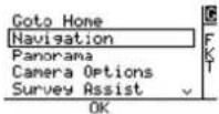 | Selecting Navigation and pushing ENT opens the following screen: [New Home Position] Circle of Interest OK | Pushing ENT when New Home Position is highlighted sets the current position of the UAV as the new home position regardless if the UAV is in the air or on the ground, and brings you back to the Main Screen.Pushing ENT when Circle of Interest is highlighted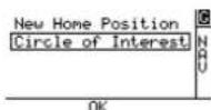 - opens the screen Rotation Angle you see to the right. - opens the screen Rotation Angle you see to the right. | By default, the home position is set where the propellers are started. This function allows setting the home position to a different place.Rotation Angle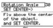 - In this screen, you can define the angle and the radius of the circle the UAV should perform. - In this screen, you can define the angle and the radius of the circle the UAV should perform. | It will affect the Goto Home function and the landing position if either ComeHome Straight or ComeHome High is selected as Link Loss Procedure.More information about the function Circle of Interest is found in “CIRCLE OF INTEREST (COI)” on page 183. |
| By pushing the RIGHT/LEFTarrow buttons you can select one of the menu points.Goto Hone Naviation Panorama Camera Options Survey Assist OK | Selecting Panorama and pushing ENT opens the following screen: [Cylindric Spherical OK] Here you can decide if you want a cylindrical or a spherical panorama. | Pushing ENT when Cylindric is highlighted opens the next screen: [START! Rotation Inc. 30 Can Angle OK] In this screen, you can start the function, and decide how many pictures are taken during one rotation of the UAV.Pushing ENT when Spherical is highlighted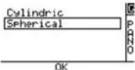 opens the screen on the right. opens the screen on the right. | More information about the option Cylindric of the Panorama function is found in “PAN-ORAMA” on page 184.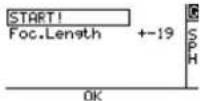 In this screen, you can start the function and modify the focus length. In this screen, you can start the function and modify the focus length. | More information about the optionSpherical of thePanorama function can be found in “PANORAMA” on page 184. |
| By pushing the RIGHT/LEFTarrow buttons you can select one of the menu points.When selecting Camera Options, the next screen depends on the mounted payload (camera). | The information on how to control the specific payload (camera) with the Status Display is found in the respective section in “PAY-LOADS - CAMERA OPTIONS” on page 31. | |||
By pushing the RIGHT/LEFTarrow buttons you can select one of the menu points.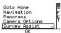 | Selecting Survey Assist and pushing ENT opens the following introductory screen: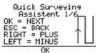 Here you see the commands for how to navigate through this function. Here you see the commands for how to navigate through this function. | Pushing ENT (OK) opens the next screen.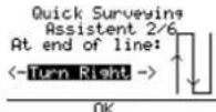 Here you can start to determine parameters for a mapping flight for rectangular areas. Here you can start to determine parameters for a mapping flight for rectangular areas. | With this function, you can determine parameters for a mapping flight for rectangular areas. | More information about the function Survey Assist is found in “QUICK SURVEYING ASSISTANT” on page 188. |
By pushing the RIGHT/LEFTarrow buttons you can select one of the menu points.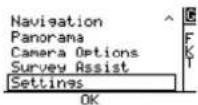 | Selecting Settings and pushing ENT opens the following menu screen: By pushing the RIGHT/LEFTarrow buttons you can select the menu point you want to control. By pushing the RIGHT/LEFTarrow buttons you can select the menu point you want to control. | Pushing ENT when the selected menu point is highlighted opens the respective screen.There are 12 different menu points available in the Settings menu:Link loss proc.Falcon InfoVideo Bind | VolumeLanguageCompass Calib'indef. ParamsService Fcts.Enter FalconIDFormat User SDBounding Box | For Link Loss proc. see “LINK LOSS PROCEDURE” on page 116.For Compass Calib. and Payload Calib.see “Payload and compass calibration” on page 36 |
Selecting Falcon Info and pushing ENT opens an information screen. and pushing ENT opens an information screen. | Here you see the serial number and the firmware versions of the current hardware components. In the last column, the activated feature packages are shown. | For further details see "Checking Activated Software Features" on page 89.Pushing ESC brings you back to the menu. | Selecting Video Bind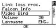 and pushing ENT establishes (again) the video connection between the UAV and the CTR. and pushing ENT establishes (again) the video connection between the UAV and the CTR. | |
Selecting Volume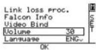 and pushing ENT highlights the number behind. and pushing ENT highlights the number behind. | By pushing the RIGHT/LEFT arrow buttons you can modify the volume of the audible messages of the Status Display of the CTR. | A range from 10 (low volume) to 100 (high volume) is available.Pushing ENT confirms the selection.Pushing ESC brings you back to the menu. | see "Intel® Cockpit Controller (CTR) Overview" on page 24 | |
Selecting Language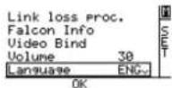 and pushing ENT highlights the field to the right. and pushing ENT highlights the field to the right. | By pushing the RIGHT/LEFT arrow buttons you can select between English (ENG) and German (GER). Push-ing ENT confirms and pushing ESC brings you back to the menu. | Selecting Def.Params 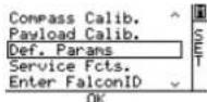 and pushing ENT opens a new screen. Here you can reset the CTR to factory defaults if the connection to the UAV ID was lost. A new pairing has to be done. and pushing ENT opens a new screen. Here you can reset the CTR to factory defaults if the connection to the UAV ID was lost. A new pairing has to be done. | Selecting Service Fcts.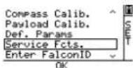 and pushing ENT opens a special screen. This function is only for service personal. and pushing ENT opens a special screen. This function is only for service personal. | For Compass Calib. and Payload Calib. see "Payload and compass calibration" on page 36 |
SelectingEnterFalconID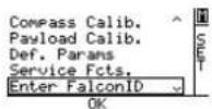 and pushingENT opens the following screen. and pushingENT opens the following screen. | Falcon Serial:1000OK ESCHere you can connect to another Intel®FalconTM 8+ UAV by entering the serial number (ID) of the respective UAV (see above) and pushing ENT (OK). | Pushing ESC brings you back to the Main Screen. | ||
SelectingFormatUser SD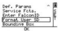 and pushingENT opens the following screen. and pushingENT opens the following screen. | SD FORMAT Refomat? Press ENT! Go back? Press ESC!This function allows to format the User SD card. | Pushing ENT confirms the formatting of the User SD card. The process starts and a progress bar is shown. | Pushing ESC cancels the function and brings you back to the Main Screen. | see “INTEL® FALCONTM 8+ UAV FLIGHT LOGS” on page 91 for further details. |
Selecting Bounding Box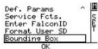 and pushingENT opens the following screen. and pushingENT opens the following screen. | By pushing the RIGHT/ LEFT arrow buttons you can switch between the settings for Radius and Height and Activate and Deactivate. | Pushing ENT when selected Radius or Height highlights the field behind. By pushing the RIGHT/ LEFT arrow buttons you can modify the selected value.Selecting Activate/Deactivate activates/deactivates the function.Pushing ENT confirms the selection and brings you back to the Main Screen. | ||
4.1.2. The Main Information Screens
The following section describes the nine main information screens of the Status Display in detail.
Figure 4.2: Main Information Screens
| Bat: 16.1V GPS: Distance: 0001 m OK | Orientation Screen Displays the UAV orientation regarding its starting position. The displayed V-shape of the UAV will turn respectively when the heading of the Intel® Falcon™ 8+ UAV is changed. This can be of help when the orientation of the UAV is difficult to see in low contrast situations such as when flying in front of dark trees. The screen shows the following information: Bat: 16.1V = Voltage level of the Intel® Falcon™ 8+ UAV battery. This is the same information as on the Main Screen. G = Flight Mode. This is the same information as on the Main Screen. GPS = Quality indicator of the GPS signal. This is the same information as on the Main Screen. Distance = Direct line of sight distance between UAV and Home Position, and only visible when airborne at a distance of at least 10 m. Graphical display of UAV orientation = Orientation of the UAV regarding the Home Position, and only visible when airborne at a distance of at least 10 m. OK = Status line. Same information as on the Main Screen. |
| Lat. +48.0952104 Long. +11.3646875 Speed 0.0m/s Qual. 99% Sats: 13 Hor.Acc. 1.1m Vel.Acc. 0.2m OK | GPS Info Screen Displays details regarding the GNSS reception quality. Lat. = Latitude of the UAV position. G = Flight Mode. This is the same information as on the Main Screen. Long. = Longitude of the UAV position. Speed = GPS measured flight speed of the UAV. Qual. = Satellite reception quality. Sats: = Number of satellites which can be received. Hor.Acc. = Horizontal accuracy in meters (m). Vel.Acc. = Velocity accuracy in meters per second (m/s). OK = Status line. This is the same information as on the Main Screen. |
| Link 36 UP Pack 33 22 DN Pack 24 L R OK | Data Link Screen Displays the quality of both data links of the sys- tem. Helpful to analyze the situation if there are Link Weak! warnings. G = Flight Mode. This is the same information as on the Main Screen. Left (L) and right (R) bars = Signal strength of left and right data link (derived from the number of transmitted data packages). Left graph · solid line = signal to noise ratio (SNR) on the left data link of the CTR · dotted line = SNR on the right data link of the CTR Right graph · solid line = SNR on the left data link of the Intel® Falcon™ 8+ UAV · dotted line = SNR on the right data link of the Intel® Falcon™ 8+ UAV UP Pack = Uploaded data packages per second from the CTR to the flight system. DN Pack = Downloaded data packages per sec- ond from the flight system to the CTR. OK = Status line. This is the same information as on the Main Screen. |
Pitch +15.53
Roll -0.57
Yaw +350.34
INS
OK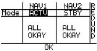 | Attitude Angles Screen Displays pitch, roll and yaw angles of the UAV. Pitch = Pitch angle of the UAV. G = Flight Mode. This is the same information as on the Main Screen. Roll = Roll angle of the UAV. Yaw = Heading direction of the UAV OK = Status line. This is the same information as on the Main Screen.Flight Controller ScreenShows an overview of two Trinity flight controller modules (NAV1 and NAV2). The third flight controller (PER - peripheral processor) is monitoring these two. In flight, one controller is active and displayed as redundant. As soon as the third one detects an issue, it will switch to NAV2 and give an acoustic and optical warning.NAV1 = 1st Trinity flight controller module (navigational processor 1).NAV2 = 2nd Trinity flight controller module (navigational processor 2).Mode = Current mode of the NAV1 and NAV2 Trinity modules.ACTV = NAV1 is active.STBY = NAV2 is in standby.ALL OKAY = No issues detected by the system.REDUND = No issues detected by the system and the flight controllers are working redundantly.OK = Status line. This is the same information as on the Main Screen. |
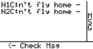  | Error Message Screen (optional)This screen is only displayed if there are system warnings. In this case the status line will show<- Check Msg.In “AscTec Trinity Control Unit System Warnings” on page 156, you will find detailed descriptions and a list of possible system warnings.N1C:n’t fly home - (= can’t fly home) warning from 1st Trinity flight controller (no GPS signal and Goto Home activated).N2C:n’t fly home - (= can’t fly home) warning from 2nd Trinity flight controller (no GPS signal and Goto Home activated).<- Check Msg in status line. Shown whenever there is a system warning.Motor ScreenThe speed of each motor is displayed graphically and indicated by a number. The numbers are not rounds per minute, but rather a coefficient. The screen can be used to analyze a motor defect warning, see “Motor Failure Warning” on page 155 for further details.G = Flight Mode. Same information as on the Main Screen.0 = Motors are right now not spinningOK = Status line. Same information as on the Main Screen. |
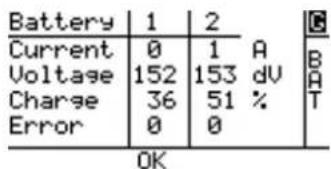 | Battery ScreenShows the actual state for each of the 2 batteries inserted in the UAVCurrent = Actual current of each battery in ampereVoltage = Actual voltage of each battery in decivolt (dV)Charge = Charge state of each battery in percentError = Number of errorsOK = Status line. This is the same information as on the Main Screen. |
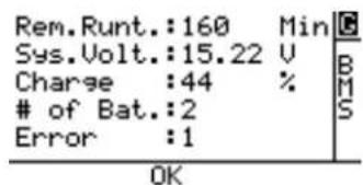 | BMS ScreenShows the actual state of the UAV.Rem. Runt. := Remaining runtime of the UAV in minutesSys. Volt. := Actual system voltage Charge: = Charge state of the UAV in percent# of Bat. := Number of batteries inserted in the UAVError: = Number of errorsOK = Status line. This is the same information as on the Main Screen. |
5. SPECIAL FUNCTIONS
This chapter offers a description of several functions to perform semi-automatic flights directly from the Intel® Cockpit Controller (CTR). Most of these functions can only be executed in GPS-Mode and require a good GPS reception.
5.1. CIRCLE OF INTEREST (COI)
This function is an optional part of the Inspection Package (see Chapter 2.8 Software Feature Packages). With the Circle of Interest (COI) it is possible to fly an automated 360° circle around an object, and take photos at predefined positions. These photos can later be processed by 3D modeling software such as Agisoft PhotoScan, to build a 3D model of the object.
Figure 5.1: Circle of Interest
| Pushing ENT in the Main Screen opens the screen below: Goto Home Navigation Panorama Camera Options Survey Assist OK Selecting Navigation and pushing ENT opens the following screen: New Home Position Circle of Interest NBU OK | Selecting Circle of Interest and pushing ENT opens the next screen: Rotation Angle: Sets the angle after which the next photo will be taken. For example, one image every 30° = 360° / 30° = 12 images. Push ENT to change the angle. Use the arrow RIGHT/LEFT button to increase, or decrease the angle. Confirm by pushing ENT. SET CENTER->: Sets the center of the Circle of Interest at the current position of the UAV. Fly to the exact center of the Circle of Interest. Tilt the camera down 90°, and use the preview video image to identify the center. At the desired position, push ENT to confirm SET CENTER->.The next screen is opened. |
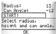 | |
| Warning:Make sure that there are no obstacles on the flight path of the Circle of Interest! | Fly backwards. The distance of the UAV to the center, (which was set in the previous step) defines the radius of the Circle of Interest.If necessary adjust the altitude of the UAV (left control stick) to the desired height, if necessary.Adjust the camera tilt angle by using the rocker switch R1 on the CTR to get the desired image framing.Confirm START! by pushing ENT. The UAV will fly a circle with the set parameters. |
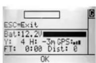 | During the COI flight, the Status Display shows a progress bar. It also displays:Bat: battery voltageY: yaw angleH: heightGPS: GPS signal qualityFT: flight timeDist: distance from home positionThe COI flight can be interrupted by giving a strong control stick command on the CTR or by pushing the ESC button of the Status Display. |
5.2. PANORAMA
With the panorama function, the Intel ^® Falcon ^™ 8+ UAV can take images at predefined positions, optimized for later stitching the images into one, large panorama shot. The speed of the Intel ^® Falcon ^™ 8+ UAV is set automatically to always have 2 seconds in between images. Any photo editing software with panorama stitching functionality, or specialized panorama software, may be used to do the image post processing.
General tips for panorama photography
Recommended camera settings:
- Image quality: RAW (Because of the large amount of data, it is important to use a fast SD card in the camera. Otherwise, there is the danger that not all images of the panorama will be captured, all data cannot be stored fast enough.)
- White balance: manual
- Shooting mode: M
- Focus: manual
- ISO: manual
- Set the display to show the histogram
Steps to set the shooting parameters:
- On the ground:
- Set the aperture wide open.
- Adjust the shutter time so that the preview video can be clearly seen.
- Focus manually to a point at hyper focal distance (never beyond the closest object in the image).
- Depending on the light conditions, set the aperture to approximately 8 and the shutter speed to approximately 1/1000s.
• Take off and fly to the panorama position.
- Turn the Intel® Falcon™ 8+ UAV and camera towards the darkest area of the image.
- Adjust aperture and shutter speed (do not use shutter speeds slower than 1/640s and try to avoid apertures under 5.6 or over 14) so that the image is under exposed by a maximum of 1.3 f-stops.
- Turn the Intel® Falcon™ 8+ UAV and camera towards the brightest area of the image.
- Use the histogram to check the exposure. Make sure that the image is not over exposed more than 1.3 f-stops. If necessary, adjust the exposure.
Thanks to the RAW format, over and under exposed images can be corrected in post processing. To stitch the images, use any software with the respective functionality to create panoramas.
There are two options available, cylindrical and spherical panorama.
Figure 5.2: Cylindrical Panorama
To create images for a cylindrical panorama, the Intel ^® Falcon ^™ 8+ UAV will keep its current position and do one 360° turn around the yaw axis, with one fixed tilt angle of the camera. Follow these steps to do a cylindrical panorama:
Do all necessary camera adjustments, take off and fly the Intel ^® Falcon ^™ 8+ UAV to the desired position.
Adjust the camera tilt angle.
Figure 5.2: Cylindrical Panorama (Continued)
Push ENT on the Main Screen of the Status Display. The screen below is opened: 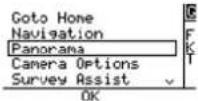 | |
Selecting Panorama and pushing ENT opens the following screen: 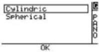 | Selecting Cylindric and pushing ENT opens the next screen. |
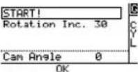 | By default, the Intel® FalconTM 8+ UAV will take an image every 30° while turning around the yaw axis. Meaning that 360°/30° = 12 images will be created. To adjust the rotation angle, use the arrow LEFT button to activate Rotation Inc. and confirm by pushing ENT. The field behind Rotation Inc. is highlighted. |
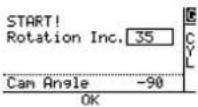 | Use the arrow RIGHT/LEFT button to adjust the angle in steps of 5° and confirm by pushing ENT. The camera tilt angle is also displayed and can still be adjusted by using the rocker switch R1 on the CTR. |
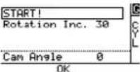 | Use the arrow LEFT button again to select START! and confirm by pushing ENT. The Intel® FalconTM 8+ UAV makes a 360° turn around the yaw axis and take all images with the settings determined in the previous steps. The panorama can be stopped anytime by the pilot by giving a strong control stick command on the CTR. |
Figure 5.3: Spherical Panorama
| To create images for a spherical panorama, the Intel® FalconTM 8+ UAV will keep its current position, and do multiple 360° turns around the yaw axis. The camera tilt angle is set to point downwards during the first turn. With every subsequent turn, the camera will be tilted upwards a bit further, until it will point fully upwards during the last turn. Follow these steps to do a spherical panorama:Do all necessary camera adjustments, take off and fly the Intel® FalconTM 8+ UAV to the desired position. | |
Push ENT on the Main Screen of the Status Display. The shown screen is opened: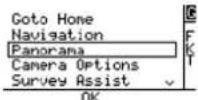 | |
Selecting Panorama and pushing ENT opens the following screen: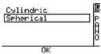 | Selecting Spherical and pushing ENT opens the next screen. |
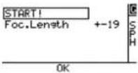 | There are two presets available for focal lengths of 19 mm and 30 mm (referring to APS-C sized sensors, equals approx. 28 mm and 45 mm referring to full frame). Use the arrow RIGHT button to activate Foc. Length and confirm by pushing ENT. The field behind Foc. Length is highlighted. |
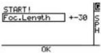 | Use the arrow RIGHT/ LEFT button to change the focal length. Confirm by pushing ENT. |
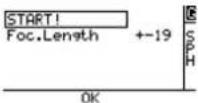 | Use the arrow LEFT button to activate START! and confirm by pushing ENT.The camera will be tilted downwards and the Falcon will start doing multiple 360° turns while slowly tilting the camera further upwards, until the spherical panorama is completed.The panorama can be stopped anytime by the pilot by giving a strong control stick command on the CTR. |
Table 5.1: Image Positions of Spherical Panorama Set To 19 mm Focal Length
| CAMERA PITCH ANGLE (DEGREES) | UAV YAW ANGLES (DEGREES) | |||||||||||
| Row 1 -7 | 4 0 90 180 270 | |||||||||||
| Row 2 -5 | 5 0 51 102 15 | 4 205 | 257 | 308 | ||||||||
| Row 3 -3 | 7 0 36 72 108 | 144 | 180 | 216 | 252 | 288 | 324 | |||||
| Row 4 -1 | 8 0 30 60 90 | 120 | 150 | 180 | 210 | 240 | 270 | 300 | 330 | |||
| Row 5 0 | 0 30 60 90 12 | 0 150 | 180 | 210 | 240 | 2 | 70 | 300 | 330 | |||
| Row 6 18 | 0 30 60 90 1 | 20 150 | 180 | 210 | 240 | 270 | 300 | 330 | ||||
| Row 7 37 | 0 36 72 108 | 144 | 180 | 216 | 252 | 288 | 324 | |||||
| Row 8 55 | 0 51 102 154 | 205 | 257 | 308 | ||||||||
| Row 9 74 | 0 90 180 270 | |||||||||||
| Total: 78 images | ||||||||||||
Table 5.2: Image Positions Of Spherical Panorama Set To 30 mm Focal Length
| S.A. UAV YAW ANGLES (DEGREES) | |||||||||||||||||||
| Row 1 | -83 0 | 180 | |||||||||||||||||
| Row 2 | -69 0 | 51 1 | 021 | 542 | 052 | 573 | 08 | ||||||||||||
| Row 3 | -55 0 | 32 6 | 5 98 | 130 | 163 | 196 | 229 | 261 | 294 | 327 | |||||||||
| Row 4 | -41 0 | 25 5 | 1 77 | 102 | 128 | 154 | 180 | 205 | 231 | 257 | 282 | 308 | 334 | ||||||
| Row 5 | -27 0 | 22 4 | 5 67 | 90 | 112 | 135 | 157 | 180 | 202 | 225 | 247 | 270 | 292 | 315 | 337 | ||||
| Row 6 | -13 0 | 20 4 | 0 60 | 80 | 100 | 120 | 140 | 160 | 180 | 200 | 220 | 240 | 260 | 280 | 300 | 320 | 340 | ||
| Row 7 | 0 | 0 20 | 40 | 60 | 80 | 100 | 120 | 140 | 160 | 180 | 200 | 220 | 240 | 260 | 280 | 300 | 320 | 340 | |
| Row 8 | 13 0 | 20 4 | 0 60 | 80 | 100 | 120 | 140 | 160 | 180 | 200 | 220 | 240 | 260 | 280 | 300 | 320 | 340 | ||
| Row 9 | 27 0 | 22 4 | 5 67 | 90 | 112 | 135 | 157 | 180 | 202 | 225 | 247 | 270 | 292 | 315 | 337 | ||||
| Row 10 | 41 0 | 25 5 | 1 77 | 102 | 128 | 154 | 180 | 205 | 231 | 257 | 282 | 308 | 334 | ||||||
| Row 11 | 55 0 | 32 6 | 5 98 | 130 | 163 | 196 | 229 | 261 | 294 | 327 | |||||||||
| Row 12 | 69 0 | 51 1 | 021 | 420 | 525 | 730 | 8 | ||||||||||||
| Row 13 | 83 0 | 180 | |||||||||||||||||
| Total: 154 images | |||||||||||||||||||
5.3. QUICK SURVEYING ASSISTANT
This function is available as part of the Survey Package. Survey Assist offers a quick and easy way to do a mapping flight over a rectangular area, directly from the CTR without any prior planning on a computer. To do so, the Intel ^® Falcon ^™ 8+ UAV is placed in one corner of the area to be mapped, and the key parameters are entered: attached camera / lens combination, desired ground sample distance, image overlaps, length of the lines and number of lines. With this data, the resulting flying altitude and flight path is calculated and carried out. An assistant guides the user through all required steps.
Images can later be processed with photogrammetry software as with any regular preplanned mapping flight. More complex flights should be planned and performed with the AscTec Navigator Software.
In the near future AscTec Navigator Software will be replaced by the advanced flight planning software Intel Mission Control. For up to date information, please check: http://www.intel.com/IntelMissionControl.
Figure 5.4: Quick Surveying Assistant
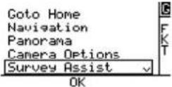 | Pushing ENT in the Main Screen opens the screen to the left.Use the arrow RIGHT/ LEFT button to select Survey Assist and push ENT. |
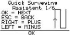 | An introduction screen is opened, explaining the commands to navigate the menu.Pushing ENT opens the next screen.Pushing ESC brings you back to the previous screen.Use the arrow LEFT/RIGHT button to increase or decrease values. |
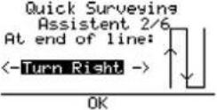 | At the end of line: Define the direction in which the Intel® FalconTM 8+ UAV turns after completing the first line of images.Use the arrow RIGHT/LEFT button to select Turn Right or Turn Left and push ENT. The next screen opens. |
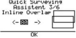 | Inline Overlap: Define the percentage of image overlap in the direction of flight (along track). |
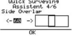 | Side Overlap: Define the percentage of image overlap between the lines (cross track). |
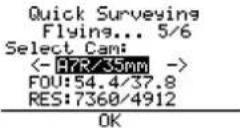 | Select Cam: Select camera/lens combination attached to the Intel® FalconTM 8+ UAV. The most commonly used cameras are available as a preset.FOV: shows the angle of the Field Of View.RES: shows the resolution of the single picture in pixels. The convention is to describe the pixel resolution with the set of two positive integer numbers, where the first number is the number of pixel columns (width), and the second is the number of pixel rows (height), for example as 7680 by 6876.If your camera is not available as a preset, chose one from the list, which matches the resolution and field of view. |
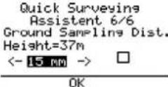 | Ground Sampling Dist.: Define the required ground sample distance (GSD). The resulting flight altitude (Height) is calculated and shown above the value of the GSD. |
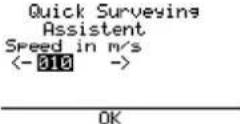 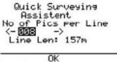 | Speed in m/s: Define the speed with which the mapping flight shall be performed (1 m/s - 10 m/s).When setting the speed, always make sure that the camera has sufficient time between waypoints. The time required by the camera to reliably trigger and store all images of a waypoint flight, depends on:Image resolution: The higher the resolution, the more data there is to process and store.File format and image quality: RAW images contain the most information and are the largest files, high quality settings will need more time during JPEG compression and more space to store.Writing speed of the SD card: If the card is too slow, this will slow down the saving process.Image content: Motives with complex structures (i.e. meadows, forest) will need more time and space during JPEG compression than plain and simple motives (i.e. roads, flat unstructured surfaces).No of Pics per Line: Define the number of images per line. The resulting length, which is covered by the images is calculated and displayed (Line Len:) underneath the number of images. |
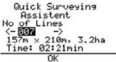 | No of Lines: Define the number of lines which shall be flown. The resulting area, which will be covered by the images, is calculated and displayed in ha (hectare). The estimated required flight time to perform the flight is also presented. |
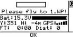 | Please fly to 1.WP!: Fly the Intel® FalconTM 8+ UAV to the corner of the rectangle, where the mapping flight is supposed to start with the first image. Adjust the heading (yaw) of the system to define the direction of the flight. Use the video preview as a help to precisely define the direction. |
 | ENT=Done!: When the system is at the right spot and oriented correctly, confirm by pushing ENT. The Intel® FalconTM 8+ UAV will first fly to the calculated altitude and then perform the mapping flight with the set parameters. |
 | Flying...:During the flight a bar shows the progress. At the end of the matrix the Intel® FalconTM 8+ will stop automatically. Push ESC to exit the screen and go back to the main menu.A Survey Assist flight can always be interrupted by giving a strong control stick command on the CTR or by pushing ESC. |
5.4. WAYPOINT NAVIGATION USING ASCTEC NAVIGATOR SOFTWARE
This functionality is part of the Survey Package (see “SOFTWARE FEATURE PACKAGES” on page 87). The AscTec Navigator Software enables planning and performing complex flight patterns for remote surveying applications. Pre-planned AscTec Navigator Software flight missions are exported to an USB stick, which is plugged into one of the USB ports numbered 2-4 of the CTR. This flight plan can be loaded and executed using the NAVIGATOR function of the Cockpit Control application on the touchscreen tablet (see “AscTec Navigator Software Projects” on page 111). At each waypoint an image is triggered, and the current GPS position is stored in the Intel® Falcon™ 8+ UAV log. Images and GPS information can later be used in photogrammetry software to create orthomosaics, digital surface models or 3D models.
Please refer to the AscTec Navigator Software Manual for detailed information. The manual can be found here: http://intel.com/FalconManual.
In the near future AscTec Navigator Software will be replaced by the advanced flight planning software Intel Mission Control. For up to date information, please check: http://www.intel.com/IntelMissionControl.
6. MAINTENANCE, TROUBLESHOOTING, AND SUPPORT
This chapter provides you with answers for questions which might appear during your work with the Intel® Falcon™ 8+ UAS. In the first section, we inform you how to keep your Intel® Falcon™ 8+ UAS up to date and give instructions to preserve the functionality. In the second section, you find troubleshooting solutions to common problems with data links. The third section provides you with the necessary data when you need direct help.
6.1. MAINTENANCE
As described in the guideline and in “SAFETY FIRST” on page 7, the general condition of the system must be checked before each flight. Thoroughly follow the check lists to make sure that the system is in flawless condition. If anything unusual is detected - which cannot be resolved - do not fly, instead get in touch with the support team. Always make sure you have the latest firmware version installed on your system.
6.1.1. Intel® Falcon™ 8+ UAS firmware updates
The latest Intel® Falcon™ 8+ UAS firmware, and step by step update instructions are available in the download area: http://intel.com/FalconDownloads.
Regularly check this website for firmware updates. To guarantee flawless operation, the Intel Cockpit Controller and the Intel Falcon 8+ UAV must always be on the same firmware version.
The firmware update for the Intel® Falcon™ 8+ UAS consists of four separate files, which are packed into a .ZIP file. The .ZIP file is called IF8P_firmware_vx.x.ZIP, with x.x being the latest firmware version, e. g. IF8P_firmware_v1.0.ZIP. After the .ZIP file is unpacked there will be the following four files:
- TRINITY. ATF: Firmware update file for the Intel ^ Falcon ^TM 8+ UAV
- COCKPIT. ATF: Firmware update file for the Intel® Cockpit Controller (CTR)
- CockpitControlInstaller_vx.x.x.exe: Update file for the Intel® Cockpit Control application running on the touchscreen tablet
- Intel-OBL-Mobile-Computing-Platform-Software-Limited-License.pdf: Outbound license file (OBL). Please read the license file before installing the firmware/software. By installing the firmware/software, you agree to the included OBL.
The firmware of the Intel ^® Falcon ^™ 8+ UAV consists of two different components:
- NAV: Navigational Processor = flight controller module of the AscTec Trinity Control Unit. There are two Navigational Processors, NAV1 and NAV2, built into an Intel® Falcon™ 8+ UAV.
- PER: Peripheral Processor = flight controller module of the AscTec Trinity Control Unit. In addition to the two Navigational Processors, there is a third flight controller module built in.
Each firmware/software (TRINITY.ATF, COCKPIT.ATF, and CockpitControl-Installer_vx.x.x.exe) has its own version number. The currently installed firmware versions can be checked in the menu of the Status Display. Pushing ENT in the Main Screen opens the menu. Navigate to Settings > Falcon Info.
To check the installed version of the Cockpit Control application, tap on the info button in the lower left corner when the application is running. The About screen displays the currently installed version.
After performing an update, we recommend checking in the Falcon Info screen of the Status Display and in the About screen of the Cockpit Control application if the newly installed firmware version is correctly displayed. If a different version is displayed, the update was not successful and must be repeated.
Updating the Intel ^® Falcon ^™ 8+ UAS
Visit http://intel.com/FalconDownloads and download the latest firmware IntelFalcon8+_firmware_vx.x.ZIP.
Note
On the website, there is also a file available, providing information regarding changes and known issues of the latest firmware/software. Before updating the UAS firmware/software, make sure to read the release notes in order to understand the expected behavior due to the changes made in the firmware/software.

CAUTION: WHEN PERFORMING A FIRMWARE/SOFTWARE UPDATE, AL-WAYS USE FULLY CHARGED BATTERIES. ALWAYS INSERT TWO BATTER-IES IN THE INTEL® FALCON™ 8+ UAV. WHILE PERFORMING AN UPDATE, NEVER REMOVE THE BATTERIES AND NEVER SWITCH OFF THE INTEL® FALCON™ 8+ UAV, THE CTR, OR THE TOUCHSCREEN TABLET. YOU MAY DAMAGE YOUR SYSTEM.
After you read the release notes and downloaded the IntelFalcon8+ firmware .ZIP file, unzip the file onto your computer. Please read the Intel-OBL-Mobile-Computing-Platform-Software-Limited-License.pdf (OBL). By installing the firmware/software you agree to the included OBL.
Copy the files TRINITY.ATF, COCKPIT.ATF and CockpitControlInstaller_vx.x.x.exe onto an empty USB stick (max. 16 GB, file system: FAT32, allocation size: 32 kilobytes) and safely remove the USB stick from your computer.
| Note | Please keep the original USB stick that was supplied with your UAS if possible and use this USB stick for all updates. If you experience any difficulties during the update process, e.g. that the USB is not detected by the UAV or the Cockpit Controller, try reformatting the USB stick with the aforementioned parameters. |
6.1.1.1. Updating the Intel ^® Falcon ^™ 8+ UAV
The Intel ^® Falcon ^™ 8+ UAV is updated by a file called TRINITY. ATF. This file must be copied onto the USB stick before you start.
Table 6.1: Updating the Intel ^® Falcon ^™ 8+ UAV
| STEP OPERATION | |
| 1. Plug the USB stick containing the TRINITY.ATF file into the USB port on the backside of the Intel® FalconTM 8+ UAV (see no. (2) in “Central Unit Back View without Gimbal (Camera Mount)” on page 20). | |
| 2. | Push the Intel® FalconTM 8+ UAV power button until there is a short beep from the UAV. |
| 3. Let go of the power button.The LED position lights of the UAV will start flashing with the beginning of the update procedure.Depending on the updated components, the update can take between 10 and 45 minutes.The end of the update process is indicated by a short melody from the UAV and the LED position lights will stop flashing. | |
| 4. | To power OFF the UAV, push the Intel® FalconTM 8+ UAV power button until a short beep from the UAV is heard. |
| 5. Let go of the power button. | |
| 6. Once the UAV is OFF, unplug the USB stick.If the update was successful, the file on the USB stick will be renamed to _TRINITY.ATF. | |
| 7. | Check that the file was renamed, and additionally check if the new version is displayed in the Falcon Info screen of the Status Display. |
© 2018 Intel Corporation. All rights reserved 195
6.1.1.2. Updating the Intel ^® Cockpit Controller (CTR)
The CTR is updated by a file called COCKPIT. ATF. This file must be copied onto the USB stick before you start.
The firmware update of the CTR can only be done with the port labeled USB 1 at the backside of the CTR (see Figure 2-7. Intel® Cockpit Controller (CTR) overview).
Table 6.2: Firmware Update for the CTR
| STEP OPERATION | |
| 1. | Plug the USB stick containing the COCKPIT.ATF file into the port USB 1 on the backside of the CTR. |
| 2. | Switch ON the touchscreen tablet and wait until the Preflight Checklist is shown. |
| 3. Switch ON | the CTR.When the update process starts, the Status Display will show Starting X%... and the percentage number will increase as the update progresses.In addition, the Status Display will show several messages regarding the update status of internal components.Depending on the updated components, the update can take between 10 and 45 minutes.At the end of the update process Done will be displayed shortly and the Status Display will show the Start Screen. |
| 4. Switch OFF | the touchscreen tablet. |
| 5. Switch OFF | the CTR. |
| 6. Unplug the USB stick. | If the update was successful, the file on the USB stick will be renamed to _COCKPIT.ATF. |
| 7. | Check that the file was renamed, and additionally check if the new version is displayed in the Falcon Info screen of the Status Display. |
Note To save time, it is possible to do the firmware update of the CTR and the Intel ^® Falcon ^™ 8+ UAV in parallel.
6.1.1.3. Updating the Cockpit Control Application
The Cockpit Control application is updated by a file called CockpitControl-Installer_vx.x.x.exe. This file must be copied onto the USB stick before you start.
The firmware update of the Cockpit Control application can only be done with the USB ports 2 to 4 on the backside of the CTR ("Intel® Cockpit Controller (CTR) Overview" on page 24).
Table 6.3: Firmware Update for the Cockpit Control Application
| STEP OPERATION | |
| 1. Plug the USB stick containing the CockpitControlInstaller_vx.x.x.exe file into one of the USB ports labeled USB 2, USB 3 or USB 4 on the backside of the CTR. | |
| 2. Switch ON the touchscreen tablet. | |
| 3. Switch ON the CTR. | |
| 4. | Confirm the Preflight Checklist of the Cockpit Control application. |
| 5. Tap on the info button in the lower left corner of the touchscreen tablet. | |
| 6. | In the next screen tap on Updates in the lower left corner. All update files found on the USB stick will be displayed in the center of the screen. |
| 7. Tap on the update file that should be installed. A dialog will pop up. | |
| 8. | Tap on YES to confirm the dialog. The Cockpit Control application will be closed. |
| 9. | Confirm the next dialog Cockpit Control Setup Wizard with tapping on Install. A progress bar will be shown. When the update is finished, there will be a respective message. |
| 10. | Tap on Finish to confirm this message. You will be asked to restart the system. |
| 11. | Tap on Yes to confirm. After the restart, the dialog for time and date settings is shown. |
| 12. If necessary, adjust the time and date. | |
| 13. | Tap on APPLY SETTINGS. |
| 14. | Confirm the Preflight Checklist. |
| 15. Tap on the info button in the lower left corner. | |
| 16. | Check the installed Cockpit Control version in the about dialog.The newly installed version should be shown. |
6.1.2. Caring for the Intel ^® Falcon ^™ 8+ UAV
Please consider the next points in order to keep the UAV in good condition; so it will be ready for use every time.
- Strict compliance with the Safety Guidelines and Safety Precautions ensures that defects are found before a flight (UAV and safety check, pre-flight check and post-flight check, see “UAS AND SAFETY CHECK” on page 11).
- We recommend an annual check from the manufacturer, during which the system is fully tested. For details please contact your reseller or Intel support.
Cleaning
If necessary, you should clean the UAV after the mission, and before storing.

CAUTION: IF YOU USE WATER, NO MOISTURE/WATER SHOULD REACH THE MOTORS OR ELECTRICAL CONTACTS.
- Use a soft lint-free cloth (e.g. microfiber) for cleaning the outer parts (motor rails, canopy, propellers) carefully.
- If indicated you can moisten the cloth with warm water, to which you can add a mild dish-washing detergent if necessary.
- A small, soft paintbrush can be used for dry cleaning.
- For cleaning (especially the motors) and drying you can also use canned compressed air, which is available at many computer stores.

CAUTION: WHEN YOU USE COMPRESSED AIR FOR CLEANING THE UAV, IT IS MANDATORY TO HOLD/FIX THE PROPELLERS DURING THE BLOWING OUT PROCEDURE. OTHERWISE, VOLTAGES CAN BE GENERATED, WHICH CAN DAMAGE THE SYSTEM ELECTRONICS.
Storing
• Always disconnect all batteries when the system is no longer in use.
- Store in a place that is not subject to large temperature fluctuations and direct sunlight.
• Make sure the storage place is dry and that no condensation moisture can come into contact on with the system.
- Best practice is to always keep the UAV in the closed approved case.
Transportation
Only transport the system in the case or the backpack as described, see "TRANSPORT CASES & INTEL® BACKPACK" on page 81.
6.1.3. Propeller replacement
Before taking-off, check all propellers for any signs of defects such as scratches, cracks or stress points (whitening - color change of the propeller surface caused by abnormal bending). If a blade shows any defect, it should be replaced before the next flight.

CAUTION:
• CORRECT INSTALLATION OF ANY PROPELLER IS CRITICAL TO OPERATING AND FLYING THE UAV SAFELY.
• INCORRECT INSTALLATION OF ANY PROPELLER - BY ATTACHING ANY PROPELLER INCORRECTLY RESULTING IN THE PROPELLER(S) FALLING OFF IN FLIGHT OR BY ATTACHING ANY PROPELLER IN THE WRONG DIRECTION (E.G. PUTTING A LEFT-TURNING PROPELLER ON A RIGHT-TURNING PROPELLER MOUNT OR DOING THE OPPOSITE) MEANS:
- IF ONE PROPELLER WERE INSTALLED INCORRECTLY, THE UAV MAY BECOME UNABLE TO COMPENSATE FOR LOSING THAT PROPELLER; AND
- IF MORE THAN ONE PROPELLER WERE INSTALLED INCORRECTLY, IT IS VERY LIKELY THE UAV WILL BECOME UNSTABLE, UNCONTROLLABLE, AND CRASH.
- INCORRECT INSTALLATION OF ANY PROPELLER BY TIGHTENING THE NUT HOLDING ANY PROPELLER(S) WITH TORQUE ABOVE THE TORQUE SPECIFICATION OF 20 NCM +-5 NCM WILL CAUSE THE MOTOR SHAFT TO PULL UPWARDS AND THE MOTOR TO HAVE MUCH HIGHER RESISTANCE WHEN TURNING THE PROPELLER, WILL REQUIRE HIGHER POWER TO TURN THE MOTOR, WILL AGE THE MOTOR FASTER, AND MAY EVENTUALLY STOP THE MOTOR IN-FLIGHT.
• IF THIS WERE TO HAPPEN WITH ONE MOTOR, THE UAV MAY BECOME UNABLE TO COMPENSATE, WHICH MAY CAUSE A CRASH; AND
- IF THIS HAPPENS WITH MORE THAN ONE MOTOR, IT IS VERY LIKELY THAT THE UAV WILL BECOME UNSTABLE, UNCONTROLLABLE, AND CRASH.
Figure 6.1: Changing the propellers of the UAV
| The only tool you need for changing a propeller blade is the 5.5 mm wrench, which is delivered with your Intel® Falcon™ 8+ UAV. 1. Loosen the nut, of the defective propeller with the 5.5 mm wrench. 2. Lift the propeller carefully – without too much pressure downwards on the motor. Note: There are two varieties of propellers (right- and left-spinning). The propeller direction is shown on the propeller by an arrow (see example for a right spinning propeller in the figure to the left). 3. Check the propeller spin of the dismounted propeller. 4. Align the new propeller with the correct propeller spin to fit onto the propeller mount. 5. Press the propeller completely down on the mount. 6. Put the new self-tightening nut onto the motor shaft. 7. Hold the motor head with thumb and index finger of one hand to prevent the motor shaft from spinning. 8. Tighten the nut with the 5.5 mm wrench (20 Ncm +- 5 Ncm). To do so, turn the screw-wrench with the index finger of the other hand. As soon as the motor head starts turning as well, sufficient force has been applied. 9. Check if the propeller is spinning freely when you nudge it. Depending on the applied force, the propeller must make several turns. 10. Check the orientation of the propeller once more and compare the movement with the other propellers. |
It is mandatory to test the UAV after replacing/mounting a propeller. Follow the UAS and Safety Check ("UAS AND SAFETY CHECK" on page 11) thoroughly. If you do not notice anything unusual (any loose part, strange noise from the motors, or any other unusual occurrence), prepare the UAS to do a test flight on a wide open field without any close by obstacles.
Follow the Pre-flight Check ("PRE-FLIGHT CHECK" on page 13) thoroughly to prepare the Intel Falcon 8+ UAS for take-off. Once airborne, perform flight maneuvers in all directions and observe if the UAV performs as expected. If it does, land the system and follow the Post-flight Check ("POST-FLIGHT CHECK" on page 16). If you notice any impaired flight performance, immediately land the UAV and try to identify the cause. If in doubt or if you require professional support, please contact support through your reseller. Please include a detailed description of your observation and photos if applicable.
6.1.4. Motor rail replacement
If a motor rail needs to be exchanged, follow the procedures outlined in this chapter.
To order a motor rail, please contact your dealer. There is no difference between the left and the right motor rail of the Intel Falcon 8+ UAV.
Figure 6.2: The motor rail
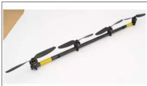
natural_image
Black and yellow propeller aircraft with four blades, mounted on a white surface (no text or symbols visible)For packing reasons, a replacement motor rail will be delivered with the two outer propellers unmounted. For instructions how to mount the propellers, please refer to chapter "Propeller replacement" on page 200. The image to the right shows the motor rail with already mounted propellers.
In addition to the motor rail, the following tools and materials are required:
• T6 torx screw driver (included in the Intel Falcon 8+ UAS case)
- Loctite 248 (included in the Intel Falcon 8+ UAS case)
- 2 x Screw M2x18 mm TX, FK (re-use from the motor rail that will be replaced)
The following figures show step by step instructions how to exchange a motor. In the single images
- red arrows and red circles are used to emphasize a specific region or detail of a part or assembly,
- white arrows are used to indicate a movement (straight arrow) or a rotation (bend arrow) of a part or assembly.
Figure 6.3: Removing a motor rail from an Intel Falcon F8+ UAV
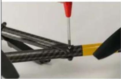 | 1. Remove the screw M2x18 mm TX, FK of the motor rail at the front end of the UAV.Use a T6 torx screw driver. |
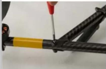 | 2. Remove the screw M2x18 mm TX, FK of the motor rail at the back end of the UAV.Use a T6 torx screw driver. |
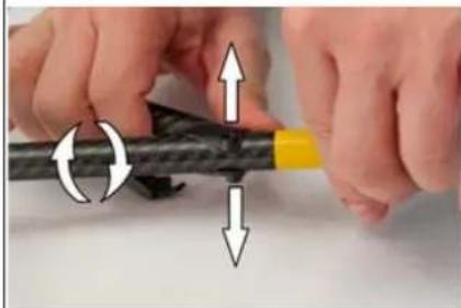 | 3. Push the two ends of the connecting plug of the front cross tube away from the motor rail.Use only a slight force.Rotate the motor rail by a small amount to loosen the connector.NOTICE: Possible breakage of the connector.Do not rotate the motor rail too much. |
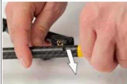 | 4. Push the motor rail straight out of the connecting plug of the front cross tube. |
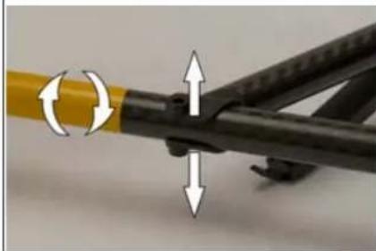 | 5. Push the two ends of the connecting plug of the rear cross tube away from the motor rail.Use only a slight force.Rotate the motor rail by a small amount to loosen the connector.NOTICE: Possible breakage of the connector.Do not rotate the motor rail too much. |
Figure 6.3: Removing a motor rail from an Intel Falcon F8+ UAV (continued)
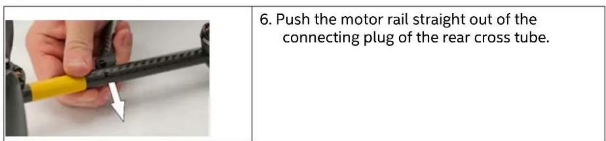
Before mounting a motor rail, perform the following checks:
Figure 6.4: Checks do be done before mounting a motor rail
| 1. On the Intel Falcon 8+ UAV, make sure the golden pins of the cross tube connectors: • show no wear • are free of dirt • are not bent. | |
| 2. Make sure the connecting plugs of the cross tube are free of cracks and damages. | |
| 3. Make sure the thread bushings of the connecting plugs of the cross tube are free of damage. | |
| 4. On the replacement motor rail, make sure the connectors of the motor speed controller: • show no wear • are free of cracks • are free of dirt. |
© 2018 Intel Corporation. All rights reserved 204
After these before described checks you can now mount the motor rail.

CAUTION:
CORRECT INSTALLATION OF A NEW MOTOR RAIL IS CRITICAL TO OPERATING AND FLYING THE UAV SAFELY.
INCORRECT INSTALLATION OF A NEW MOTOR RAIL BY NOT ATTACHING IT CORRECTLY TO THE CARBON CROSS AS SHOWN IN THE BELOW PICTURES WILL CAUSE THE MOTOR RAIL TO BECOME LOOSE IN FLIGHT DUE TO THE VIBRATION OF THE UAV AND WILL CAUSE LACK OF CONTROL AND CRASHING, AS WELL AS POSSIBLE INJURY TO PERSONS OR PROPERTY.
Figure 6.5: Mounting a motor rail onto an Intel Falcon F8+ UAV
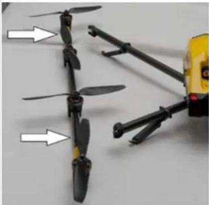 | 1. Align the motor rail to the cross tubes. Make sure there is no horizontal tilt of the motor rail.NOTICE: Risk of damage to the motor rail connectors and the motor rail controllers if the motor rail is attached with lateral offset.Make sure there is no lateral offset between motor rail and cross tube connectors. |
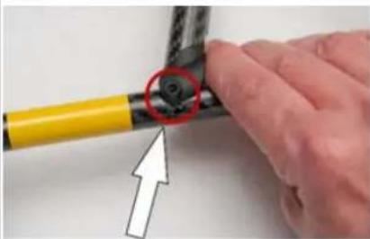 | 2. Attach the motor rail to the rear cross tube.Refer to the picture how to align the bore of the connecting plug to the bore in the motor rail.NOTICE: Always start with the rear cross tube. |
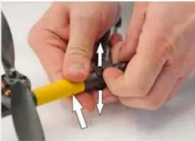 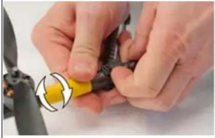 | 3. Push the two ends of the connecting plug of the rear cross tube away from each other.Push the motor rail into the connecting plug of the cross tube.Use no force.4. Rotate the motor rail by a small amount until it fits.NOTICE: Possible breakage of the connector.Do not rotate the motor rail too much.Make sure the pin of the center cross is inserted in the jack of the motor rail.If necessary retract the motor rail and start again. |
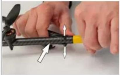 | 5. Push the two ends of the connecting plug of the front cross tube away from each other.Push the motor rail into the connecting plug of the cross tube.Use no force. |
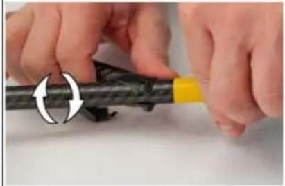 | 6. Rotate the motor rail by a small amount until it fits.NOTICE: Possible breakage of the connector.Do not rotate the motor rail too much.Make sure the pin of the center cross is inserted in the jack of the motor rail.If necessary retract the motor rail and start again. |
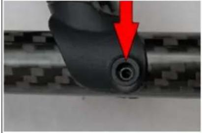 | 7. Make sure the bores of the front and rear connecting plugs are correctly aligned to the bores in the motor rail. |
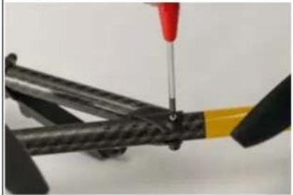 | 8. Apply thread locking agent Loctite 248 to the 2 screws M2x18 mm TX, FK.9. Attach the screw M2x18 mm TX, FK on the front cross tube.Use a T6 torx screw driver.Make sure the screw can be attached without drag.10.Tighten the screw.11. Attach the screws M2x18 mm TX, FK on the rear cross tube. Use a T6 torx screw driver. Make sure the screw can be attached without drag. 12.Tighten the screws. Make sure that it is not possible to rotate or to move the motor rail. |
| 13. Make sure there is no gap between motor rail and the connecting plugs of the front and the rear cross tube. |
It is mandatory to test the UAV after replacing a motor rail. Follow the UAS and Safety Check ("UAS AND SAFETY CHECK" on page 11) thoroughly. If you do not notice anything unusual (any loose part, strange noise from the motors, or any other unusual occurrence), prepare the UAS to do a test flight on a wide open field without any close by obstacles.
Follow the Pre-flight Check (“PRE-FLIGHT CHECK” on page 13) thoroughly to prepare the Intel Falcon 8+ UAS for take-off. Once airborne, perform flight maneuvers in all directions and observe if the UAV performs as expected. If it does, land the system and follow the Post-flight Check (“POST-FLIGHT CHECK” on page 16). If you notice any impaired flight performance, immediately land the UAV and try to identify the cause. If in doubt or if you require professional support, please contact support through your reseller. Please include a detailed description of your observation and photos if applicable.
6.1.5. Exchanging a payload adapter
The payload adapter is the connection between the camera mount and the central unit of the UAV. If necessary, it can be exchanged.
The only tool you need for exchanging a payload adapter is the T6 torx screw driver, which is delivered with your Intel® Falcon™ 8+ UAV.
To order a payload adapter, please contact your dealer.
The payload adapter consists of the following parts:
Figure 6.6: The parts of the payload adapter
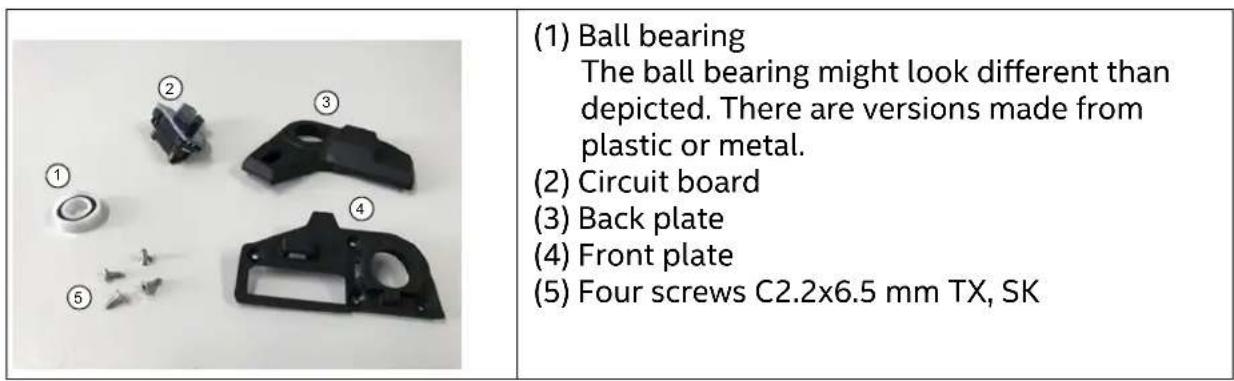
The following figures show step by step instructions how to exchange a payload adapter.
In the single images
- red arrows and red circles are used to emphasize a specific region or detail of a part or assembly;
- white arrows are used to indicate a movement (straight arrow) or a rotation (bend arrow) of a part or assembly.
Figure 6.7: Removing a payload adapter from a payload
| 1. Remove the 4 screws C2.2x6.5 mm TX, SK. Use a T6 torx screw driver. Make sure not to apply force to the servo motor. | |
| 2. Disconnect the front plate and the back plate of the payload adapter. 3. Disconnect the 10 pin wire connector. | |
| 4. Remove the front plate from the payload rod. 5. Remove the back plate from the payload rod. |
The following figures show step by step instructions how a new payload adapter has to be attached to a payload.
The payload adapter is delivered in pieces.
For the single parts of the payload adapter see "The parts of the payload adapter" on page 208.
Figure 6.8: Attaching a new payload adapter
| 1. Attach the board to the back plate. | |
| 2. Attach the ball bearing to the front plate. | |
| 3. Slide the front plate assembly onto the rod of the payload. |
Figure 6.8: Attaching a new payload adapter
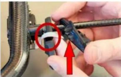 | 4. Slide the back plate assembly onto the rod of the payload.5. Align the ribbon cable correctly in the gap of the front plate.6. Connect the 10 pin wire connector.7. Attach the back plate assembly to the front plate assembly.Make sure not to apply force to the servo motor. |
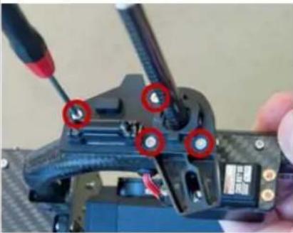 | 8. Attach and tighten the 4 screws C2.2x6.5 mm TX, SK with a T6 torx screw driver. |
6.1.6. Updating a payload from an AscTec Falcon 8 UAV to an Intel Falcon 8+ UAV
The following payloads for the AscTec Falcon 8 UAV can be updated to become compatible with the Intel Falcon 8+ UAV:
- Sony Alpha 7R
• Inspection Payload with the Panasonic Lumix DMC-TZ71
The update requires three steps:
- Update the hardware with a payload adapter.
Please refer to the section "Exchanging a payload adapter" on page 207 for instructions.
- Perform a payload calibration.
When the payload is first connected, there will be two warning messages, No calib on payload found and Payload EEPROM compromised!. Please do a payload calibration by performing all steps described in chapter "Payload calibration" on page 36. This will resolve the warning No calib on payload found.
- Update the eeprom flash of the payload.
Contact the Intel support team and provide the following information:
- Payload type (Sony Alpha 7R or Inspection Payload TZ71)
© 2018 Intel Corporation. All rights reserved 210
- Payload serial number (can be found on a label on the bottom of the gimbal). Older payloads might not have a serial number label on the gimbal. If there is none on your payload, please mention that as well.
With the information you provided, the support team is able to create an update file called "f8p_license.asc", which will be emailed to you. The file may come in the form of a ZIP file. Please store this file on your computer, if necessary unzip it and follow the step by step instructions below.
- Take the USB stick from your Intel ^® Falcon ^™ 8+ UAV.
- Plug it into your computer.
- Format the USB stick (file system: FAT32, allocation unit size: 32 kilobytes).
- Copy the "f8p_license.asc" file into the root directory of the USB stick.
- Plug the USB stick into the Intel ^® Falcon ^™ 8+ UAV.
- Switch ON the UAV.
- After the initialization of the Intel ^® Falcon ^™ 8+ UAV is complete, wait 10 seconds. Then switch OFF the UAV.
- Remove the USB stick from the Intel ^® Falcon ^™ 8+ UAV.
- Power on the UAS.
- Check that the message EEPROM compromised is no longer shown.
- Check if the camera controls from the CTR work as described in the respective chapter regarding this camera.
Note
A payload that has been updated to become compatible with the Intel Falcon 8+ UAV can again be converted to use it with the AscTec Falcon 8 UAV. The AscTec Falcon 8 UAV must have firmware NAV / PER version 0.50 or later installed. For instructions on how to check the currently installed firmware and where to download the latest firmware version, please refer to chapter "6.1.1 Firmware and updates" in the AscTec Falcon 8 UAS user manual.
To convert a payload back to the AscTec Falcon 8 UAV, the payload adapter needs to be removed and a payload calibration must be performed on the AscTec Falcon 8 UAV. Please refer to chapter "2.4.1 Payload and compass calibration" in the AscTec Falcon 8 UAS user manual for a detailed description on how to do a payload calibration.
The AscTec Falcon 8 UAV will initially show an error message No calib on payload found, when a payload that has been used on the Intel Falcon 8+ UAV is connected. The payload calibration will resolve this error message.
If the payload shall again be used on the Intel Falcon 8+ UAV, it is sufficient to mount the payload adapter again and perform a payload calibration. The update file "f8p_license.asc" will no longer be needed after it has been successfully used during the initial conversion.
6.2. TROUBLESHOOTING
This chapter describes solutions for special problems.
6.2.1. Establishing a connection between the CTR and the UAV
The UAV and the CTR are pre-configured ex works.
Nevertheless, when the Intel ^® Falcon ^™ 8+ UAV and the CTR are powered up for the first time, the Status Display will show the Start Screen and it is necessary to set up the connection between UAV and CTR.
If the UAV and the respective CTR have been linked before, the UAV will automatically connect to the CTR as soon as both are turned on.
In some cases, it may be necessary to establish the connection manually again.
Note It saves some time to switch on the UAV first, so that the system check is being carried out. Then switch on the touchscreen tablet followed by the CTR.
Figure 6.9: Connecting the CTR to the UAV
|  Waiting for link ENT=Search RIGHT=Last Position | If the UAV and the CTR do not automatically connect, the Status Display will note it in the Start Screen. If this is the case, you must establish the connection manually. 1. Push the ENT button of the Status Display (see "STATUS DISPLAY" on page 166). You will see the screen to enter the Falcon Serial number (5-digit serial number of the Intel ^ Falcon ^TM 8+ UAV,printed on the top of the UAV, above the battery compartment, for example 31123). The first digit is highlighted (see figure below). |
| Falcon Serial:1000OK ESC | 2. Push ENT to activate the first digit.3. Enter the first digit of the serial number by using the arrow RIGHT/LEFT buttons to increase/ decrease the number. RIGHT increases the number, LEFT decreases it.4. Push ENT to confirm the first digit. The next digit can be entered.5. Repeat this five times (for every digit)6. Push ENT to confirm the serial number. OK is highlighted.7. Push ENT and the connection will be established. |
6.2.2. Analyzing Data Link Connection Issues
In some cases, the data link may be disturbed. If this happens please do the following:
- Check that the antenna panel of the CTR is unfolded and oriented towards the UAV and that there are no visible defects like cracks or breaks.
- When performing a test, make sure that there are no disturbing (WiFi) networks in the 2.4 GHz range. They will influence the results.
- Use the Data Link Screen of the Status Display (see "The Main Information Screens" on page 178) to check if an issue always occurs on the same link.
- If there is a persistent issue on one of the data links, it might be a defect either on the UAV transmitter / receiver modules or on the CTR transmitter / receiver modules. To check for this defect, please test the following if you have a second CTR / Intel® Falcon™ 8+ UAV available:
- Take the CTR of the problematic Intel ^ Falcon ^TM 8+ UAV, and connect it to a different Intel ^ Falcon ^TM 8+ UAV and repeat the test.
If the issue persists it is very likely the CTR, if the issue disappears it very likely comes from the Intel ^® Falcon ^™ 8+ UAV.
- Take a new CTR and connect it with the problematic Intel® Falcon™ 8+ UAV and repeat the test.
If the issue persists it is very likely the Intel ^® Falcon ^™ 8+ UAV, if the issue disappears it very likely is coming from the CTR.
When the issue has been isolated, please contact the support team, describe your finding precisely and be prepared to provide log files of the flight tests.
If you do not have a second CTR / Intel® Falcon™ 8+ UAV available, contact Intel support.
6.2.3. No preview video on the touchscreen tablet of the CTR
If there is no video preview image, please first check:
• The connection between the camera and the Intel® Falcon™ 8+ UAV
- That the camera, Intel ^ Falcon ^TM 8+ UAV, the touchscreen tablet and the CTR are properly switched ON
- Payload:
The signal from the payload might not be fed correctly into the Intel® Falcon™ 8+ UAV. Please check the payload adapter. If you have a different payload available, please attach it and check the video reception.
• Video transmitter of the Intel® Falcon™ 8+ UAV:
If you have one available, please use a different Intel® Falcon™ 8+ UAV system, and check if you can receive the video signal from that Intel® Falcon™ 8+ UAV with the original CTR.
If you can receive video from a different UAV, there is an issue with the video transmission of the original Intel® Falcon™ 8+ UAV.
• Video receiver of the Intel® Falcon™ 8+ UAV:
If you have one available, please use a different CTR, connect it with your Intel® Falcon™ 8+ UAV and check if you can receive the video signal with this CTR. If you can receive video with a different CTR, there is an issue with the video reception on the original CTR.
When the issue has been isolated, please contact the support team, describe your finding precisely and be prepared to provide log files of the flight tests.
If you do not have a second CTR / Intel® Falcon™ 8+ UAV available, contact Intel support.
6.2.4. Flight logs
It might happen that the Intel ^® Falcon ^™ 8+ UAV cannot access a logging storage device (see “INTEL ^® FALCON ^™ 8+ UAV FLIGHT LOGS” on page 91). Mostly, the reason is a mechanical connection issue or a corrupted file system on the storage device.
If the Intel ^® Falcon ^™ 8+ UAV cannot access a storage device, a respective warning will be displayed:
Table 6.4: Possible warnings
| CAUSE | VISUAL SIGNAL | POSSIBLE FIX |
| User SD card can-not be accessed. | <- Check Msg appears in the status line of the Status Display. Push the related arrow LEFT button on the CTR until the Error Message Screen is shown. No user SD card will be shown. | Take out the User SD card, make a backup copy and format it (file sys-tem: FAT32, allocation unit size: 32 kilobytes). After reinserting the SD card into the Intel® FalconTM 8+ UAV, it should be accessible.If no backup copy is needed, the User SD card can also be formatted directly by the UAV. To do so:1. Push ENT to open the menu on the Status Display.2. Push the arrow RIGHT button to navigate to Settings.3. Push ENT and use the arrow RIGHT button to navigate to Format User SD.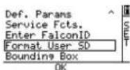 4. Push ENT to confirm. The shown screen appears: 4. Push ENT to confirm. The shown screen appears: 5. Push ENT to confirm the formatting of the User SD card. The process starts, a progress bar is shown. Pushing ESC cancels the function and brings you back to the Main Screen.When the formatting of the SD card is finished, the Intel® FalconTM 8+ UAV will immediately create a new log file and start logging again. 5. Push ENT to confirm the formatting of the User SD card. The process starts, a progress bar is shown. Pushing ESC cancels the function and brings you back to the Main Screen.When the formatting of the SD card is finished, the Intel® FalconTM 8+ UAV will immediately create a new log file and start logging again. |
| Internal SD card cannot be accessed. | <- Check Msg appears in the status line of the Status Display. Push the related arrow LEFT button on the CTR until the Error Message Screen is shown. No internal SD card will be shown. | Switch off the Intel® FalconTM 8+ UAV. Wait 10 seconds and switch it on again. During boot up, the internal SD card will be formatted and it should again be accessible. If this does not help, contact the support team to get instructions on how to proceed. |
The Intel ^® Falcon ^™ 8+ UAV can fly without any active logging device. It is the responsibility of the user to make sure that all flights can be properly logged if it is a legal requirement in the country where the system is used.
The User SD card will not be deleted or formatted by the flight system. We recommend to regularly make a back-up copy of this storage device and reformatting it afterwards. Especially when working on complex projects, during which the logs are needed for geo-referencing, it is helpful to start with clean storage media.
6.3. SUPPORT
Should you require support, do not hesitate to contact your local support partner. If you assume any kind of malfunction or if you happened to have had an accident with the UAV, please make sure to always supply the following information:
- Intel® Falcon™ 8+ UAV serial number (5-digit number of the Intel® Falcon™ 8+ UAV, printed on the top of the UAV, above the battery compartment, for example 31123, see “Central Unit” on page 20.
-
Intel® Falcon™ 8+ UAS firmware versions: You get access to the above-mentioned information by using the Status Display.
-
Push ENT in the Main Screen.
A menu is opened.
-
Use the arrow RIGHT button to select Settings.
-
Push ENT.
A new screen is opened.
-
Use the arrow RIGHT button to select Falcon Info.
-
Push ENT.
Now you see the serial number and the firmware versions of the current hardware components. In the last column, the activated feature packages are shown.
6. Push ESC.
You return to the Settings menu.
Further information needed:
• Detailed description of the incident / defect.
- Images or videos if applicable (please also include comments or additional explanations along with the images if necessary). In case of an accident, please take pictures of the spot where the incident occurred to help us reconstruct the situation.
- Log files from the User SD card, see "INTEL® FALCON™ 8+ UAV FLIGHT LOGS" on page 91. Please indicate as precisely as possible the log file number in which the incident occurred, or note the exact local time at which the incident occurred.
- Reproduction scenario: Please describe step by step what you do and under which circumstances / conditions the failure occurs.
- If you want to report an incident or request support, please download and fill out the Support Request Form from: http://intel.com/FalconDownloads and send it to the Intel support team.
If the system needs to be sent in for repair, please contact the support team first. They will advise the next steps.
If the UAV performed a direct landing because of a lost data link connection and if you have difficulties in locating it, the last known position of the Intel® Falcon™ 8+ UAV (which is stored in the Status Display of the CTR) might be helpful. Click the arrow RIGHT button of the Status Display once (while not connected) and latitude and longitude of the last known position will be displayed.
7. TECHNICAL SPECIFICATION
Figure 7.1: Technical Data
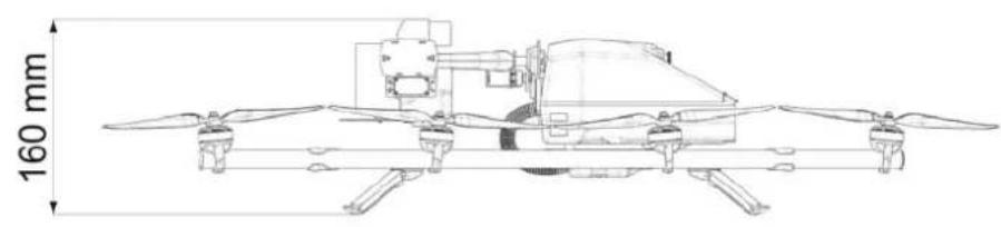
natural_image
Technical line drawing of a drone with propellers and control unit, shown with 160 mm height dimension (no text or symbols on the diagram itself)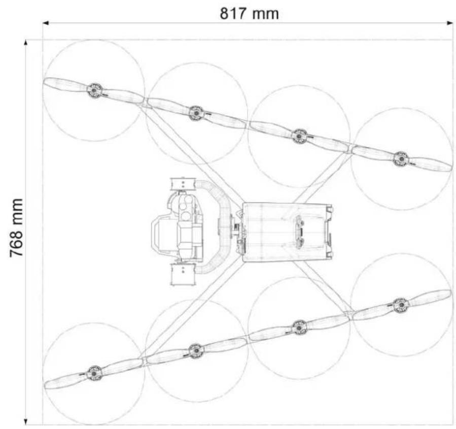
Table 7.1: Technical Data
| INTEL® FALCON ^TM 8+ UAV | |
| TYPE V-Form Octocopter | |
| SIZE 768 x 817 x 160 mm | |
| ENGINES 8 electrical, brushless (sensorless) motors with 125 W max. power each | |
| ROTOR DIAMETER 20.32 cm (8 in) | |
| NUMBER OF ROTORS 8 | |
| ROTOR WEIGHT 6 g (0.21 oz) | |
| EMPTY WEIGHT 1.2 kg (2.65 lbs) | |
| MAX. PAYLOAD WEIGHT (CAMERA AND GIMBAL) | 0.8 kg (1.76 lbs) |
| MAX. TAKE OFF WEIGHT 2.8 kg (6.17 lbs) | |
| MAX. FLIGHT TIME WITHOUT PAYLOAD* | 26 min |
| MAX. FLIGHT TIME WITH MAX. PAYLOAD WEIGHT* | 16 min |
| MAX. FLIGHT TIME WITH A7R | 16 min |
| MAX. FLIGHT TIME WITH INSPECTION PAYLOAD | 18 min |
| MAX. RANGE DATA LINK** | 1 km (FCC version) (3281 feet)850 m (CE version) (1640 feet) |
| MAX. SERVICE CEILING** | 4000 m MSL (13123 feet) |
| MAX. ALTITUDE ABOVE GROUND LEVEL** | Varies by country in which you operate the UAV and requires you to check the regulations that apply for your country of operation |
| MAX. RANGE VIDEO LINK** | 500 m (FCC and CE version) (1640 feet) |
| MAX. TOLERABLE WIND SPEED | 12 m/s (26 mph) (GPS-Mode)16 m/s (35 mph) (Height-Mode, Manual-Mode) |
| MAX. PRECIPITATION Not recommended to operate in any form of precipitation | |
| OPERATING TEMPERATURE -5 °C to 45 °C (23 °F to 113 °F) | |
| SHORT TERM STORAGE TEMPERATURE (UP TO ONE MONTH) | -5 °C to 40 °C (23 °F to 104 °F) |
| LONG TERM STORAGE TEMPERATURE (BEYOND ONE MONTH) | -5 °C to 25 °C (41 °F to 77 °F) |
| POWER SUPPLY 2 x Intel® Powerpack 4000 (redundant setup) | |
| NAVIGATION SENSORS | |
| ASCTEC TRINITY CONTROL UNIT Triple redundant Inertial Measurement Unit (IMU: barometer, compass, accelerometers, gyroscopes) | |
| GLOBAL NAVIGATION SATELLITE SYSTEM (GNSS) | GPS and GLONASS |
| MAX. AIRSPEED | |
| MANUAL-MODE 18 m/s (40 mph) | |
| HEIGHT-MODE 18 m/s (40 mph) | |
| GPS-MODE 4.5 m/s (10 mph) standard; up to 10 m/s (22 mph) in mapping flights | |
| MAX. CLIMB/SINK RATE | |
| MANUAL-MODE 6 to 10 m/s (13 to 22 mph) | |
| HEIGHT-MODE 3 m/s (6 mph) | |
| GPS-MODE 3 m/s (6 mph) | |
| MAX. TURN RATE | |
| MANUAL-MODE / HEIGHT-MODE 115°/s | |
| GPS-MODE 75°/s | |
| MAX. PITCH AND ROLL ANGLES | |
| MANUAL-MODE / HEIGHT-MODE 50° | |
| GPS-MODE 45° | |
| WIRELESS COMMUNICATION | |
| 2 INDEPENDENT (DIVERSITY) COMMAND AND CONTROL LINKS | 2.4 GHz adaptive FHSS link with 100 mW |
| DIGITAL VIDEO LINK Low latency digital link.5.1 Ghz to 5.8 GHz with up to 24 dBM / 250 mW (FCC compliant version).5.1 Ghz to 5.8 GHz with up to 20 dBM / 100 mW (CE compliant version).Resolution depending on payload up to 1080 p Full HD | |
| INTEL® COCKPIT CONTROLLER (CTR) | |
| DIMENSION (W X L X H) 320 x 380 x 135 mm (12.60 x 14.96 x 5.31 in) | |
| WEIGHT 2.7 kg (5.95 lbs) (w/o battery)3.1 kg (6.83 lbs) (with battery) | |
| POWER SUPPLY 1 x Intel® Powerpack Battery | |
| OPERATING TIME* 2 h | |
| OPERATING TEMPERATURE -5 °C to 45 °C (23 °F to 113 °F) | |
| SHORT TERM STORAGE TEMPERATURE(UP TO ONE MONTH) | -5 °C to 40 °C (23 °F to 104 °F) |
| LONG TERM STORAGE TEMPERATURE(BEYOND ONE MONTH) | -5 °C to 25 °C (23 °F to 77 °F) |
| TOUCHSCREEN | Size 8.3", resolution 1980 x 1200 px |
| CONNECTIONS 4 x USB, 1 x HDMI | |
| INTEL® POWERPACK BATTERY | |
| TYPE Lithium Polymer (LiPo) 4S | |
| CAPACITY | 4000 mAh |
| VOLTAGE (NOMINAL) | 14.8 V |
| ENERGY | 59.2 Wh |
| OPERATING TEMPERATURE*** | -5 °C to 40 °C (23 °F to 104 °F) |
| CHARGE TEMPERATURE Recommended: 10 °C to 30 °C (50 °F to 86 °F)Max.: 5 °C to 40 °C (41 °F to 104 °F) | |
| SHORT TERM STORAGE TEMPERATURE(UP TO ONE MONTH) | -5 °C to 40 °C (23 °F to 104 °F) |
| LONG TERM STORAGE TEMPERATURE(BEYOND ONE MONTH) | 18 °C to 28 °C (64 °F to 82 °F) |
| RECOMMENDED STORAGE VOLTAGE 3.7 V per cell | |
| MAX CHARGING POWER 80 W | |
| TYPICAL CYCLE LIFE 150 cycles | |
| WEIGHT 398 g (14 oz) (tolerance +/- 5%) | |
| AC ADAPTER (CHARGER FOR POWERPACK PP4000) | |
| INPUT VOLTAGE 100-240 V, 50/60 Hz | |
| MAXIMUM INPUT CURRENT 1.5 A | |
| MAXIMUM OUTPUT CURRENT 4.74 A | |
| OUTPUT VOLTAGE 19.0 V | |
| * Data is based on having new batteries, fully charged, and at room temperature. Data collection flights were performed at approximately 0 m (0 feet) above sea level at outside temperature of approximately 15 °C (59° F), no wind, slow and steady flight maneuvers, no hovering. All measurements done at International Standard Atmosphere (ISA). Other factors may have influenced the results. | |
| ** The pilot is responsible for knowing and complying with all laws and regulations applicable to the airspace in which the Intel® FalconTM 8+ System is operated. Juris-dictions have different safety rules related to authorization for flying unmanned air-craft; flying near airports, manned aircraft, or people; operation within visual line of sight; altitude limits and others. Data collection flights were performed at approxi-mately 120 m (393 feet) above ground in GPS-Mode, drone facing away from pilot, Cockpit antenna oriented exactly towards drone, no obstacles in-between line of sight to drone and 400 m radius around drone and pilot, no external disturbance of the 2.4 Ghz and 5.8 GHz bands. All measurements done at International Standard Atmosphere (ISA). Other factors may have influenced the results. | |
| *** The maximum temperature for the Intel® Powerpack depends on the system and the configuration it is used with: | |
| The Intel® FalconTM 8+ combined with the Intel® Cockpit Controller - operating temperature is 45°C (113°F) | |
| The Intel® FalconTM 8+ without a payload attached and two fully charged batteries inserted - maximum operating temperature is 45°C (113°F) | |
| The Intel® FalconTM 8+ with payload attached - maximum operating temperature is 40°C (104°F).Because of the necessary higher current, the batteries will produce more heat. | |
LIST OF FIGURES
2.1 The Intel ^® Falcon ^™ 8+ UAV Components .....18
2.2 Central Unit Back View without Gimbal (Camera Mount) 20
2.3 Central Unit Front View without Gimbal (Camera Mount) 21
2.4 Central Unit Side View, Left Side without Gimbal (Camera Mount) ......21
2.5 Motor Rails and Equipment 22
2.6 Units of the Gimbal 23
2.7 Intel® Cockpit Controller (CTR) Overview 24
2.8 Status Display 27
2.9 The Touchscreen Tablet 28
2.10 Independent Camera Control (ICC) 28
2.11 2nd Operator Monitor Package ....30
2.12 Camera Control via the Intel® Cockpit Controller (CTR) 32
2.13 Installing the Camera Mount 34
2.14 Removing the Camera Mount 35
2.15 Sony Alpha 7R and SD Card Slot 39
2.16 Sony Alpha 7R CTR Control Layout ....40
2.17 Camera Settings By Camera Sony Alpha 7R 42
2.18 Inspection Payload 43
2.19 Inspection Payload: CTR Control Layout 46
2.20 Intel® High Resolution Imaging Payload specifications ....48
2.21 Sony RX1R II CTR control layout 50
2.22 Camera settings for Sony RX1R II 51
2.23 Payload Firmware Update ....53
2.24 Intel ^® Imaging Payload Specifications ....54
2.25 Confirmation of video file transfer 58
2.26 Sony R10C CTR control layout 59
2.27 Camera settings by the control menu items on the touchscreen tablet ....60
2.28 Firmware update process 62
2.29 Obstacle Avoidance: directions covered 66
2.30 Tablet GUI with an OA payload mounted 67
2.31 LED description ....71
2.32 The Intel® Powerpack Battery 72
2.33 Charging 73
2.34 Battery Update 77
2.35 Temperature Depending LiPo Battery Capacity 80
USER MANUAL INTEL® FALCON™ 8+ UAS
2.36 Transport Cases & Backpack 81
2.37 Packing Instructions for the Intel® Falcon™ 8+ UAS Cases ....82
2.38 Packing Instructions for the cardboard box for the UAV system case .....85
2.39 Show Activated Perpetual License 90
2.40 Show activated annual license 90
2.41 AscTec Navigator Software Flightbook 92
3.1 Preparing the UAV 95
3.2 Preparing the CTR 97
3.3 The Cockpit Control Application 99
3.4 The Cockpit Control Application and PATH Projects 104
3.5 The Cockpit Control Application and PATH Projects 109
3.6 The Cockpit Control Application And AscTec Navigator Software Projects ....112
3.7 Message shown during Regional Settings 116
3.8 Magnetic Field Warning 116
3.9 The Link Loss Procedures 117
3.10 The Link Loss Procedures (Continued) 118
3.11 New Home Position 118
3.12 Last Known Position 119
3.13 Selecting he flight modes 120
3.14 GPS accuracy 122
3.15 Shadowing 123
3.16 GPS Multi Path Effects 124
3.17 Starting the motors 127
3.18 Basic flight principles 130
3.19 Left and right control sticks 131
3.20 Flight information on the Main Screen of the Status Display 133
3.21 Examples for situations to be avoided 134
3.22 System warnings 156
4.1 Status Display 166
4.2 Main Information Screens 178
5.1 Circle of Interest .... 183
5.2 Cylindrical Panorama 185
5.3 Spherical Panorama 187
5.4 Quick Surveying Assistant 189
6.1 Changing the propellers of the UAV 201
6.2 The motor rail 202
USER MANUAL INTEL® FALCON™ 8+ UAS
6.3 Removing a motor rail from an Intel Falcon F8+ UAV 203
6.4 Checks do be done before mounting a motor rail 204
6.5 Mounting a motor rail onto an Intel Falcon F8+ UAV 205
6.6 The parts of the payload adapter 208
6.7 Removing a payload adapter from a payload 208
6.8 Attaching a new payload adapter 209
6.9 Connecting the CTR to the UAV 212
7.1 Technical Data 218
LIST OF TABLES
1.1 Safety Check List .... 12
1.2 Pre Flight Check List 13
1.3 Pre Flight Checklist (Continued) 14
1.4 Post-flight Check List 16
2.1 Operating a Camera by ICC 29
2.2 Sony Alpha 7R Camera Control By Camera Functions ....41
2.3 Sony Alpha 7R Camera Control By Status Display 41
2.4 Inspection Payload: CTR Control Layout 47
2.5 Inspection Payload Control By Status Display 47
2.6 Example for a hold distance set to 5 m 68
2.7 System warnings related to Obstacle Avoidance 70
2.8 Technical Specifications of the Battery 71
2.9 Charging State 73
2.10 Charging Cycles 75
2.11 Battery Capacity 75
2.12 Battery Status 76
2.13 Package Descriptions 88
2.14 Possible Warning 93
3.1 Controlled parameters depending on the flight mode 121
3.2 Controlled parameters in GPS-Mode 121
3.3 Controlled parameters in Height-Mode 125
3.4 Controlled parameters depending on the flight mode 126
3.5 Operational guidelines in case of emergency 135
3.6 Possible Warnings 144
3.7 Warnings depending on critical battery levels of the UAV 149
3.8 Warnings depending on critical battery levels of the CTR 151
3.9 Acoustic and visual magnetic field warning 152
3.10 Diversity Data Link warnings 154
3.11 GPS signal warning 155
3.12 Motor warning (Controller) 155
3.13 AscTec Trinity Control Unit system warnings 156
3.14 Payload weight 165
4.1 Status Display Menu Structure 167
5.1 Image Positions of Spherical Panorama Set To 19 mm Focal Length ..... 188
5.2 Image Positions Of Spherical Panorama Set To 30 mm Focal Length .....188
6.1 Updating the Intel® Falcon™ 8+ UAV 195
6.2 Firmware Update for the CTR 196
6.3 Firmware Update for the Cockpit Control Application 197
6.4 Possible warnings 215
7.1 Technical Data 219
INDEX
A
AC Adapter 222
Actively Stabilized Camera Mount 23
Adjusting the camera horizon 37
Airspeed 220
Analyzing Data Link Connection Issues 213
AscTec Navigator Software Mission, Interrupting a mission 114
AscTec Navigator Software Mission, Resuming a mission 114
AscTec Navigator Software Mission, Starting and flying a mission ....113
AscTec Navigator Software, Waypoint Navigation 192
Automated Start-up Checks 115
B
Batteries, Caring for 80
Batteries, Hot swapping 96
Battery Capacity 75
Battery Disposal 80
Battery Information Safety Instructions 77
Battery Life 80
Battery Status 76
Battery Update ....77
BMS Error Mode 76
BMS Menu 74
C
Camera Control, CTR 40
Camera Options, Status Display ....41
Central Unit 20
Changing a Payload (Camera) 34
Charging 73
Charging Cycles 75
Charging State 74
Circle of Interest (COI) 183
Cleaning 198
Climb/Sink Rates 220
Compass calibration 36, 37
USER MANUAL INTEL® FALCON™ 8+ UAS
Compass Error Estimation 124
Controlling the Intel ^® Falcon ^™ 8+ UAV, CTR 131
D
Distance Guard 69
Distance Hold 68
DNX button 63
E
Emergencies, In-flight 134
Establishing a connection between the CTR and the UAV 212
E
Firmware update Sony R10C 61
Firmware update Sony RX1R II 53
Firmware updates 193
Flight 130
Flight Logs 91,214
Flight Modes 120
G
General Guidelines and Warnings, Batteries 78
Geo-reference 52
Gimbal 23
GNSS receiver 48
GPS-Mode 121
Independent Camera Control (ICC) 28
In-Flight 133
Inspection Payload 43
Inspection Payload Control, CTR 46
Inspection Payload Control, Status Display 47
Inspection Payload, General Care 45
Intel Platform Flash Tool (PFT) 61
Intel® Backpack 81
Intel® Cockpit Controller (CTR) 23, 221
Intel® Falcon™ 8+ UAS 7
Intel® Falcon™ 8+ UAV 18,219
Intel® Falcon™ 8+ UAV, Caring for 198
Intel® High Resolution Imaging Payload 48
Intel ^® Imaging Payload 54
Intel® Powerpack Batteries 71
Intel® Powerpack Batteries, Charging 73
Intel® Powerpack Battery 221
Intended Use 7
L
Landing 141
Landing, GPS-Mode 141
Landing, Height-Mode 141
Landing, Manual-Mode 142
Launching, GPS-Mode 128
Launching, Height-Mode 128
Launching, Manual-Mode 129
Limitations, Operational 165
Link Loss Procedure 116
M
Magnetic Field Warning 116
Main Information Screens 178
Maintenance 193
Manual-Mode 126
Manual-Mode, Landing 142
Manual-Mode, Launching 129
USER MANUAL INTEL® FALCON™ 8+ UAS
Mission planning 132
Motor rail replacement 202
Motor rails 22
Motors, Starting and Stopping 127
N
Navigation Sensors ....220
No Preview Video on the Touchscreen Tablet of the CTR 214
0
OA system warnings 70
Obstacle Avoidance (OA) 54, 65
Operating the System 95
Operating Tips 133
Operational Limitations 165
P
Packing Instructions 82
Panorama 184
PATH Projects 103
Payload adapter 207
Payload calibration ....36
Payloads - Camera Options ....31
Post-Flight Check 16
Pre-Flight Check 13
Preparing the Intel ^® Cockpit Controller (CTR) 97
Preparing the Intel ^® Falcon ^™ 8+ UAV .....95
Privacy and Property Rights ....11
Product Warranty 81
Propeller replacement ....200
Q
Quick Surveying Assistant 188
R
RealSense™ 54
Regional Setting 115
S
Safety First 7
Safety Guidelines 8
Second Operational Monitor 30
Shadowing 123
Situations with Varying GPS Reception 119
Software Feature Packages 87
Software Feature Packages, Activating 89
Software Feature Packages, Annual 90
Software Feature Packages, Perpetual 90
Sony Alpha 7R Full Frame Camera ....39
Sony Alpha 7R, Camera Settings ....41
Sony Alpha 7R, General Care ....39
Sony R10C RGB camera 54
Sony RX1R II 48
Special Functions 183
Standoff distance 54,66
Status Display 27,166
Storage Mode 74
Storing 199
Support 193,216
Switching OFF the UAS 143
I
Taking Off 127
Technical Specification 218
Touchscreen Tablet 28,99
Transport Cases 81
Transportation 199
Troubleshooting 193,212
Turn Rates 220
U
UAS and Safety Check 11
Updating, Cockpit Control Application ....197
Updating, Intel® Cockpit Controller (CTR) 196
Updating, Intel ^® Falcon ^™ 8+ UAV 195
W
Warnings 143
Warnings of the UAV and the CTR, Critical Battery Levels 149
Warnings, AscTec Trinity Control Unit System 156
Warnings, Battery 149
Warnings, CTR 156
Warnings, Data Link 154
Warnings, GPS 155
Warnings, Magnetic Field ....151
Warnings, Motor Failure 155
Waypoint Navigation ....192
Wireless Communication 221
- DISCLAIMER
- RECORD OF REVISION
- TABLE OF CONTENTS
- INTEL® FALCON™ 8+ UAS ....7
- DESCRIPTION OF THE SYSTEM 18
- TECHNICAL SPECIFICATION 218
- LIST OF FIGURES 224
- LIST OF TABLES 227
- INDEX 228
- INTEL® FALCON™ 8+ UAS
- SAFETY FIRST
- Intended Use
- Safety Guidelines
- Privacy and Property Rights
- UAS AND SAFETY CHECK
- PRE-FLIGHT CHECK
- POST-FLIGHT CHECK
- DESCRIPTION OF THE SYSTEM
- THE INTEL® FALCON™ 8+ UAV
- Central Unit
- Motor rails of the UAV
- Actively Stabilized Camera Mount (Gimbal)
- THE INTEL® COCKPIT CONTROLLER (CTR)
- The Status Display
- The Touchscreen Tablet
- THE INDEPENDENT CAMERA CONTROL (ICC)
- THE 2ND OPERATOR MONITOR
- PAYLOADS - CAMERA OPTIONS
- Figure 2.12: Camera Control via the Intel® Cockpit Controller (CTR) (continued)
- Setting the Camera Angle
- Changing a Payload (Camera)
- Payload and compass calibration
- Payload calibration
- Compass calibration
- Adjusting the camera horizon
- Sony Alpha 7R Full Frame Camera
- General Care
- Camera Control By The CTR
- Camera Options By The Status Display
- Camera Settings
- Inspection Payload
- General Care
- Inspection Payload Control By The CTR
- Inspection Payload Control By The Status Display
- Intel® High Resolution Imaging Payload
- General care
- Camera control by the CTR
- Camera settings
- Geo-reference
- Notes
- Possible workaround:
- Intel® Imaging Payload
- File structure of image files
- File structure of video files
- General care
- Camera control by the CTR
- Camera settings
- Obstacle Avoidance (OA)
- Conditions for using Obstacle Avoidance
- !
- Configuring Obstacle Avoidance
- Obstacle Avoidance and Flight Modes
- GPS-Mode and Distance Hold
- Height-Mode and Distance Guard
- Manual-Mode
- Landing the UAV with Obstacle Avoidance
- OA system warnings
- THE INTEL® POWERPACK BATTERIES
- Charging the Intel® Powerpack Batteries
- Operating The BMS Menu
- Menu Option 1, Charging State
- Menu Option 2, Storage Mode
- Menu Option 3, Charging Cycles
- Menu Option 4, Overall Capacity
- Menu Option 5, Battery Status
- BMS Error Mode
- Battery Update
- Battery Information Safety Instructions And Warnings
- General Guidelines and Warnings
- Charging
- Discharging
- Storage & Transportation
- Battery Storage/Charging Maintenance Recommendation
- Caring for Batteries
- Operating Temperatures
- Battery Life
- Disposal
- Product Warranty
- TRANSPORT CASES & INTEL® BACKPACK
- Packing Instructions
- Intel ® Falcon TM 8+ System Case
- Packing for shipping
- SOFTWARE FEATURE PACKAGES
- Activating Software Feature Packages
- Checking Activated Software Feature Packages
- Perpetual Software Feature Packages
- Annual Software Feature Packages
- INTEL® FALCON™ 8+ UAV FLIGHT LOGS
- PREPARING THE INTEL® FALCON™ 8+ UAV
- PREPARING THE INTEL® COCKPIT CONTROLLER (CTR)
- WARNING DO NOT POWER ON OR OPERATE THE CTR WITHOUT FULLY EXTENDING THE ANTENNA PANEL
- Main Screen
- Figure 3.3: The Cockpit Control Application (continued)
- Main Screen (continued)
- Error Messages and Warnings
- PATH Projects
- PATH PROJECT
- PATH PROJECT - NEW
- Figure 3.4: The Cockpit Control Application and PATH Projects (continued)
- New Project / Record Mode
- Loading an Existing Project
- Modifying an Existing Project
- Figure 3.5: The Cockpit Control Application and PATH Projects (continued)
- Modifying an Existing Project (Continued)
- Save PATH Project
- AscTec Navigator Software Projects
- Note
- Fly an AscTec Navigator Software Project
- Starting and flying an AscTec Navigator Software mission
- Interrupting a mission
- Resuming a mission
- AUTOMATED START-UP CHECKS
- Regional Setting
- Magnetic Field Warning
- LINK LOSS PROCEDURE
- Home Position
- Situations with varying GPS reception
- FLIGHT MODES
- GPS-Mode
- Figure 3.14: GPS accuracy
- Compass Error Estimation
- Height-Mode
- Manual-Mode
- WARNING THE MANUAL-MODE IS FOR EXPERTS ONLY
- STARTING AND STOPPING THE MOTORS
- TAKING OFF
- Launching in GPS-Mode
- Launching in Height-Mode
- CAUTION: LAUNCHING IN HEIGHT-MODE IS RECOMMENDED FOR EXPERIENCED PILOTS ONLY!
- Launching in Manual-Mode
- CAUTION: LAUNCHING IN MANUAL-MODE IS FOR EXPERTS ONLY.
- THE FLIGHT
- CAUTION: DOWNWASH
- Controlling the Intel ® Falcon ™ 8+ UAV from the CTR
- Mission planning
- In-Flight
- General Operating Tips
- IN-FLIGHT EMERGENCIES
- LANDING
- Landing in Manual-Mode
- CAUTION: LANDING IN MANUAL-MODE IS FOR EXPERTS ONLY.
- Switching OFF the UAS
- WARNINGS
- Critical Battery Levels & Warnings of the UAS
- Battery warnings of the UAV
- Battery warnings of the CTR
- Magnetic Field Warning
- Data Link Warnings
- GPS Warning
- Motor Failure Warning
- AscTec Trinity Control Unit System Warnings
- OPERATIONAL LIMITATIONS
- STATUS DISPLAY
- STATUS DISPLAY OVERVIEW
- Status Display Menu Structure
- The Main Information Screens
- SPECIAL FUNCTIONS
- CIRCLE OF INTEREST (COI)
- PANORAMA
- General tips for panorama photography
- Figure 5.2: Cylindrical Panorama
- QUICK SURVEYING ASSISTANT
- WAYPOINT NAVIGATION USING ASCTEC NAVIGATOR SOFTWARE
- MAINTENANCE, TROUBLESHOOTING, AND SUPPORT
- MAINTENANCE
- Intel® Falcon™ 8+ UAS firmware updates
- Updating the Intel ® Falcon ™ 8+ UAS
- Updating the Intel ® Falcon ™ 8+ UAV
- Updating the Intel ® Cockpit Controller (CTR)
- Updating the Cockpit Control Application
- Caring for the Intel ® Falcon ™ 8+ UAV
- Cleaning
- CAUTION: IF YOU USE WATER, NO MOISTURE/WATER SHOULD REACH THE MOTORS OR ELECTRICAL CONTACTS.
- CAUTION: WHEN YOU USE COMPRESSED AIR FOR CLEANING THE UAV, IT IS MANDATORY TO HOLD/FIX THE PROPELLERS DURING THE BLOWING OUT PROCEDURE. OTHERWISE, VOLTAGES CAN BE GENERATED, WHICH CAN DAMAGE THE SYSTEM ELECTRONICS.
- Storing
- Transportation
- Propeller replacement
- CAUTION:
- Motor rail replacement
- Exchanging a payload adapter
- Updating a payload from an AscTec Falcon 8 UAV to an Intel Falcon 8+ UAV
- TROUBLESHOOTING
- Establishing a connection between the CTR and the UAV
- Analyzing Data Link Connection Issues
- No preview video on the touchscreen tablet of the CTR
- Flight logs
- SUPPORT
- Push ESC.
- TECHNICAL SPECIFICATION
- LIST OF FIGURES
- USER MANUAL INTEL® FALCON™ 8+ UAS
- LIST OF TABLES
- INDEX
- A
- B
- C
- D
- E
- G
- L
- M
- N
- 0
- P
- Q
- R
- S
- I
- U
- W
Brand : INTEL
Model : Falcon 8+
Category : Drone