
APC-AMC2-2WCF - Système de contrôle d'accès de sécurité BOSCH - Free user manual and instructions
Find the device manual for free APC-AMC2-2WCF BOSCH in PDF.

| Product Type | Access Modular Controller 2 |
| Brand | Bosch |
| Model | APC-AMC2-2WCF / ADS-AMC2-2WCF |
| Dimensions (H x W x D) | 232 mm x 90 mm x 63 mm (9.13 in x 3.54 in x 2.48 in) |
| Weight | 503 g |
| Power Supply | 10 VDC to 30 VDC |
| Power Consumption | 60 VA max; 55 VA available for external devices |
| Reader Interfaces | 2 x Wiegand |
| Host Interfaces | RJ45 Ethernet (10/100 Mbit/s), RS-485, RS-232 |
| Inputs | 4 x 4-state analog inputs |
| Outputs | 4 x relay outputs (30 V DC max, 1.25 A max switching current) |
| Memory | Serial EEPROM + pluggable 2 GB Compact Flash |
| Display | LCD status display |
| Mounting | DIN rail (35 mm) with snap-in mechanism |
| Housing Material | ABS and Polycarbonate (UL94V-0) |
| Color | White |
| Environmental Rating | IP30 |
| Operating Temperature | 0°C to +50°C (32°F to 122°F) |
| Battery Type | Lithium CR2032 (VARTA) |
| Battery Life | Estimated 10 years; recommend replacement every 8 years |
| Tamper Switch | 2-wire external tamper contact |
| Reset Button | Yes (accessible via hole with screwdriver) |
| Protocols | BPA, SDEB (selectable via DIL switch) |
| Compliance | RoHS |
| Warranty | 3 years standard |
Frequently Asked Questions - APC-AMC2-2WCF BOSCH
User questions about APC-AMC2-2WCF BOSCH
0 question about this device. Answer the ones you know or ask your own.
Ask a new question about this device
Download the instructions for your Système de contrôle d'accès de sécurité in PDF format for free! Find your manual APC-AMC2-2WCF - BOSCH and take your electronic device back in hand. On this page are published all the documents necessary for the use of your device. APC-AMC2-2WCF by BOSCH.
USER MANUAL APC-AMC2-2WCF BOSCH
Access Modular Controller 2
ADS-AMC2-2WCF | APC-AMC2-2WCF
natural_image
Technical line drawing of a mechanical component with mounting holes and internal slots (no text or symbols)en Installation manual
Table of contents
1 Safety 4
1.1 Unpacking 5
2 Short information 6
3 Introduction 8
3.1 Description 8
3.2 Product overview 10
3.3 System overview 15
4 Installing 16
4.1 Mounting the device on a mounting rail 16
4.2 Unmounting the device from a mounting rail 17
4.3 Opening the case 18
4.4 Closing the case 19
4.5 Cabling 20
4.5.1 Conductor data for powering the controller 20
4.6 Grounding and shielding 22
4.6.1 Grounding for Host Interface 22
4.6.2 Grounding for Extension Interface 23
4.7 Connecting the power supply to the controller 25
4.8 Ethernet Host Interface 26
4.9 RS-485 Host Interface 27
5 Operating 29
5.1 Configuring Ethernet interface 29
6 Troubleshooting 30
6.1 Resetting the software 32
6.2 Resetting the device to factory default 32
7 Service and repair 34
8 Disposal 35
9 Technical specifications 36
10 Appendices 39
10.1 Connecting diagrams 39
1 Safety
Read instructions
Read all technical documentation before installing or using the device. Make sure that you have understood all information described in the technical documentation. Do not ignore safety messages, as this can cause property or personal damage. Retain instructions for future reference.
Warning!
Risk of physical injury due to blocked escape routes

The access modular controller may block escape routes if not installed correctly. To keep escape routes free:
- Use locks in fail-safe mode, so that doors will be released if power fails.
- Install manual override switches, such as break-glass or lever stations, to unlock doors in an emergency.

Warning!
Risk of explosion of lithium battery
The battery can explode if replaced incorrectly.
Replace battery with the same type as recommended by Bosch. Dispose used batteries according to the instructions of the manufacturer of the batteries.

Caution!
Fire hazard and risk of electric shock due to unauthorized spare parts and accessories
Unauthorized spare parts and accessories might lack grounding wires or other safety elements. External power supplies must be installed and put into service by qualified personnel. The service technician must use replacement parts or accessories that are specified by the manufacturer.

Notice!
Device damage due to electrostatic discharge
Protect the hardware from electrostatic discharge, especially when the device is opened. Always disconnect the controller from the power source before modifying the installation. The controller does not support hot-plugging.

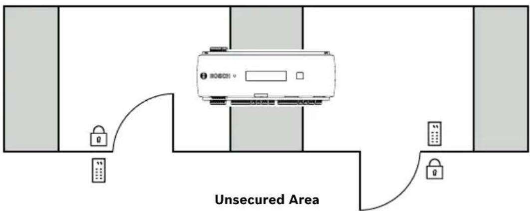
Notice!
Unauthorized access
If the access modular controller is installed in an unprotected environment, unauthorized people may be able to enter. Install the controller in a location with restricted access.

Notice!
Device damage due to incorrect mounting
The controller can fall and break. Mount the controller on the matching mounting rails.
This product is RoHS compliant. See Technical data for the full table of hazardous components.
1.1 Unpacking
Check the packaging for visible damage. If anything has been damaged during transport, please inform the transport agency. Unpack the unit carefully. This is an electronic device that must be handled with care to avoid damage. Do not attempt to put the unit into operation if components are damaged.
If any parts are missing, inform your customer service representative or a Bosch Security Systems salesperson. The shipping carton is the safest transport container for the unit. Store it and the other packaging material for future use. If the unit has to be sent back, use the original packaging.
2 Short information
This controller is able to control up to two Wiegand card readers.
It is designed to fully process the access logic at assigned access points. Access points consist of doors, gates, barriers, turn stiles, revolving doors, mantraps, ID card readers, door opening elements and sensors.
All the product versions use encrypted connections between the access modular controller and the host system.
The controller stores all necessary information in a battery-buffered memory and in a compact flash storage element. Even when the unit is offline, it is able to perform:
- Independent status and authorization checks on access points
- Take access decisions
- Activate and deactivate connected peripheral elements
- Detect and register all relevant events
The Access Modular Controller (AMC) is supported by the Access Professional Edition (APE), BIS Access Engine (ACE) and the Access Management System (AMS).
For more information about our products, visit our online product catalog.
Manufacturing dates
For product manufacturing dates, go to http://
www.boschsecurity.com/datecodes/ and refer to the serial number on the product label.
Remarks
This hardware is part of a security system.
Access should be limited to authorized people only.
Some states do not allow the exclusion or limitation of implied warranties, or limitation of liability for incidental or consequential damages, hence the above limitation or exclusion might not apply to you.
Bosch Security Systems retains all rights not expressly granted. Nothing in this license constitutes a waiver of Bosch's rights under the U.S. Copyright laws or any other federal or state law.
If you need further assistance or have any questions, contact:
Bosch Security Systems B.V.
Torenallee 49
5617 BA Eindhoven
Netherlands
www.boschsecurity.com
© Bosch Security Systems B.V., 2019
3 Introduction
3.1 Description
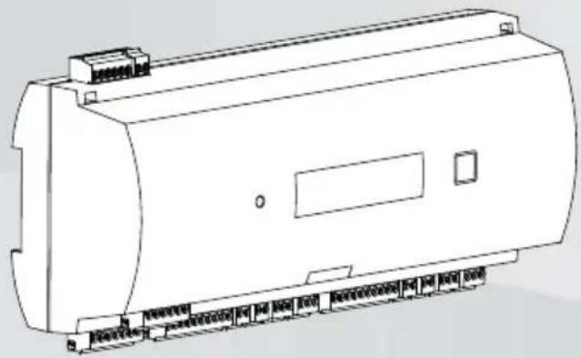
The controller is equipped with two independent interfaces for Wiegand type readers. It is able to control one door with one reader in each direction and up to two doors with a reader in one direction only.
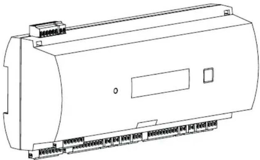
natural_image
Technical line drawing of a mechanical device casing with mounting bracket (no text or symbols)Figure 3.1: Access Modular Controller
All necessary information for access verification is stored in a battery buffered on-board memory and a Compact Flash (CF) memory card. This guarantees autonomous access decisions and complete access registrations even if the management host system is offline. The built in compact flash card provides adequate storage capability for cardholders and events.
The electronics of the controller are completely covered by a plastic housing. The LCD (liquid crystal display) provides all important status information.
flowchart
graph TD
    A["Device 1"] --> B["Unsecured Area"]
    C["Device 2"] --> B
    D["Device 3"] --> B
    B --> E["Printer Icon"]
    style B fill:#f9f,stroke:#333,stroke-width:2px
The controller can communicate upstream to the host computer using RS-485 multi-dropped. It has four analog input devices and four relay outputs. With its analog input devices, the controller verifies, for example, if a lock is closed or open. The relay outputs can be used to activate lock mechanisms if access is granted, or activate the burglar alarm system if an intrusion or system alert is detected. If the four inputs and four outputs on board are not enough to configure the system, up to three additional extension boards can be connected. The extensions offer 8 or 16 additional inputs and outputs.
The setup procedure for a controller is made very simple and fast by the use of door templates. Once selected, all the inputs and outputs are predefined. These settings can be changed to choose every free contact of the controller or a connected extension.
3.2 Product overview
Mainboard
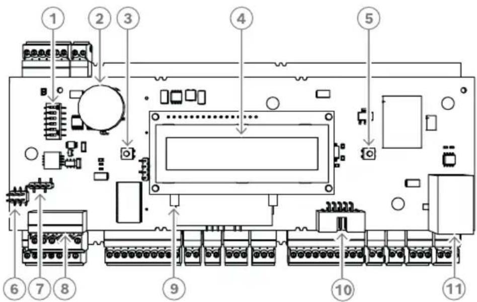
Figure 3.2: Upper circuit board with display (front)
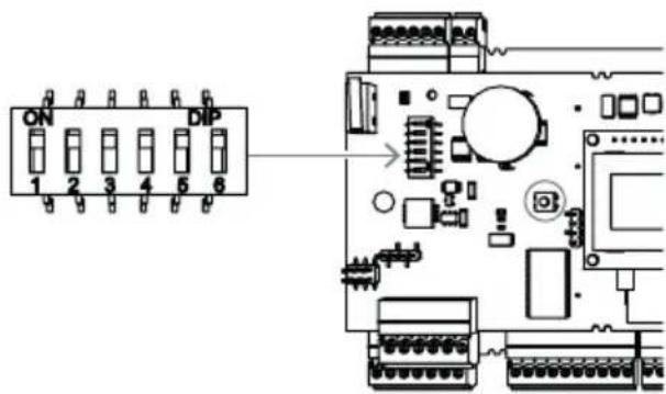
| 1 D | IL switch for RS-485 address selection, protocol, and RS-232/RS-485 selection. |
| 2 L | thium battery for buffering of static RAM and real time clock (RTC). The battery life is estimated at 10 years, nevertheless an error message is generated if the voltage sinks below a preset minimum level.NOTICE: In order to avoid an error message caused by an earlier voltage drop we suggest to replace the battery every 8 years. Spare part: VARTA CR 2032 PCB. |
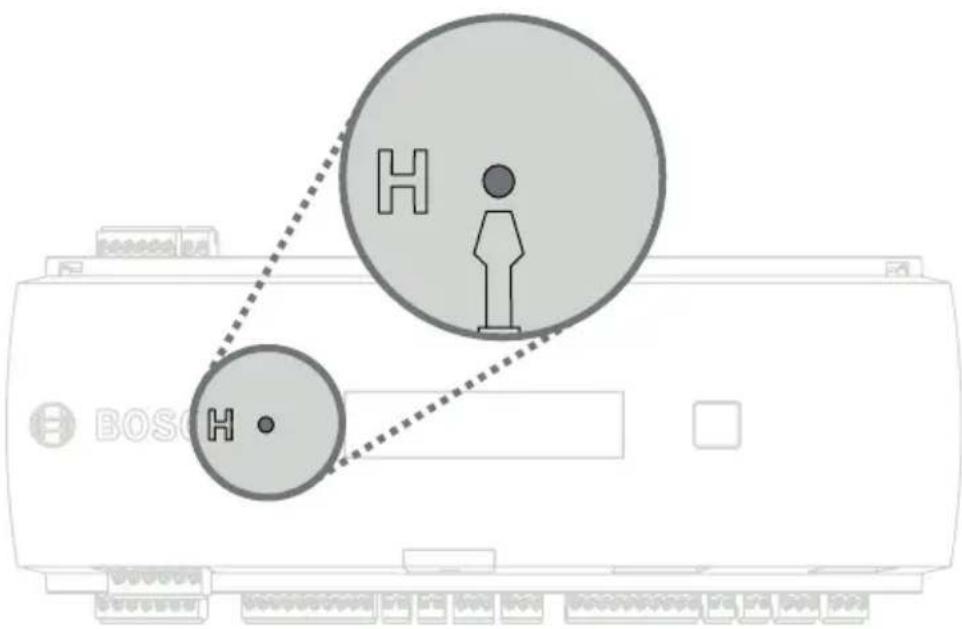
| 3 R | Reset push button - reachable through the casing using a screwdriver |
| 4 L | liquid Crystal Display |
| 5 P | push button, available on top of the housing, to select different display modes |
| 6 J | Jumper: Equalization of potential between different systems and earth ground (shield) |
| 7 Jumper: Interface selector RS-485 host connection, RS-485 two wire or RS-485 four wire (depends on external wiring) |
| 8 Configurable RS-485 host interface |
| 9 Docking port for compact flash memory |
| 10 Configurable RS-232 host interface (ribbon cable connector) |
| 11 Configurable 10/100 Mbit/s Ethernet host interface |
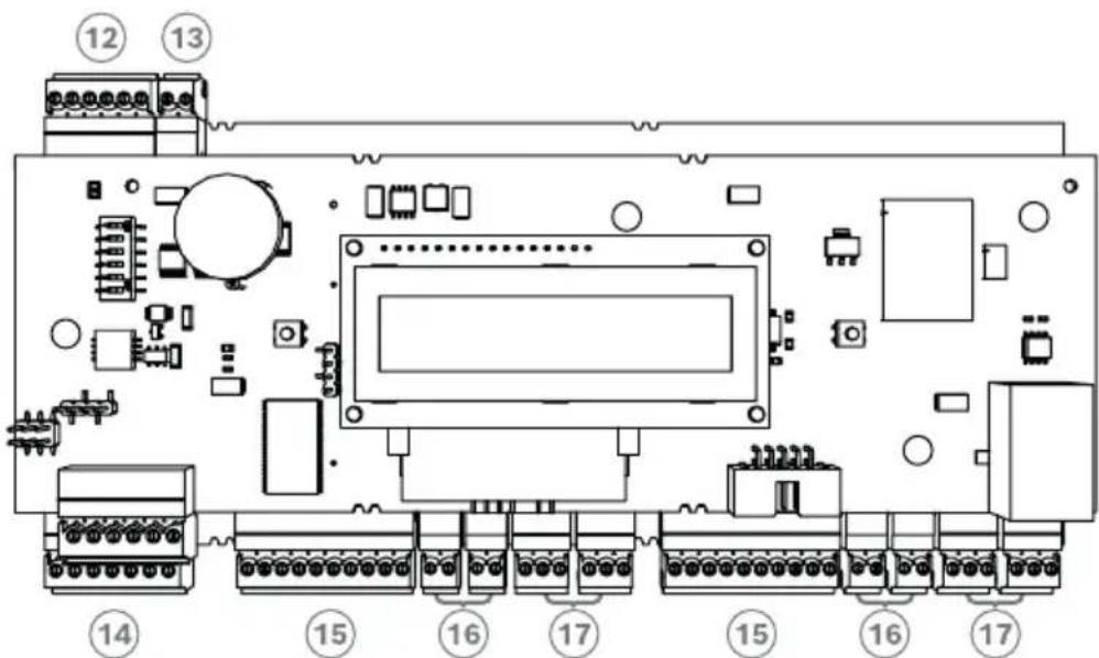
Figure 3.3: Interfaces - overview
| 12 RS-485 extension module bus |
| 13 External tamper contact |
| 14 Connector for power supply |
| 15 Wiegand interfaces for card readers |
| 16 Connectors for analog inputs |
| 17 Connectors for relay outputs |
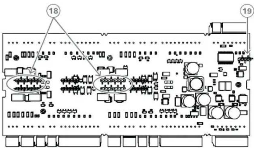
Figure 3.4: Jumper (back)
| 18 Jumper for setting either voltage free relay output (“dry” mode) or looped-in voltage from the AMC internal power supply (“wet” mode). |
| 19 Jumper: Equalization of potential between different systems and earth ground (shield) for the extension interface. |
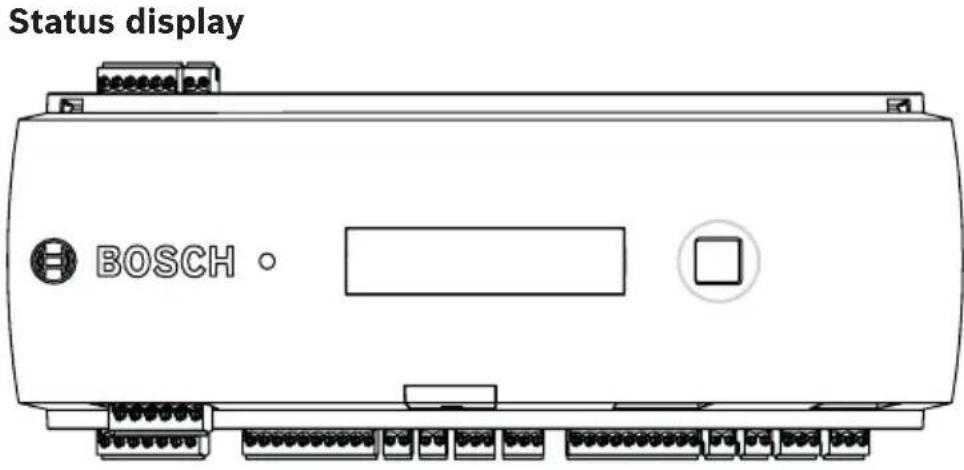
The liquid crystal display delivers status information about the controller. Push the dialog button to switch between different modes.
The selected display mode remains set until the next time the button is pressed. The order of the display pages is shown in the following table.
| Push Display (Example) Description | ||
| 0 V01.00 | 02.03.07orLBUS or BG900 | Software versions and date of the firmware - every 5 sec. alternating with the display of the reader interface. |
| 1a S/N1: 0910019212 Bosch | serial number | |
| 1b S/N2: 00000001 | ||
| 2 02.06 | 15:35:15 (S) Current | date and time(S) = Summer; (W) = Winter |
| 3 Dig. IO: :······: Display | of the digital contacts: the input signals set will be shown with an extension above - output signals with an extension below.The first eight digits display the | |
| controller's signals. The second eight digits display the extension board's signals. | ||
| 3a Dig. | 1: :********: If there | are I/O-Boards connected the signals will be shown on separate pages. |
| 3b Dig. | 12: :********: | |
| 3c Dig. | 13: :********: | |
| 4 MAC | 0010174C8A0C | Network device address (MAC) |
| 5 N AMC | -1234-5678 Network | name of the controller |
| 6 I 192. | 168.10.18 IP-address | of the controller |
| 7 G 192. | 168.10.255 IP-address | ss of the gateway (Version V 00.44 or higher) |
| 8 M 255. | .255.255.0 Subnetmask | (Version V 00.44 or higher) |
| 9 H 192. | .168.10.10 IP-address | s of the host computer |
| 10 DHCP 1 DHCP-status: | 1 = on0 = off | |
| 11 D 19 | 2.168.10.1 IP-address | s of the DNS server |
| 12 Host: + "C" Host | activity:+ = online- = offline"C" = Counter of the received data packages from the host interface.RS 485 Bus connection:A = Address 1 ... H = Address 8 | |
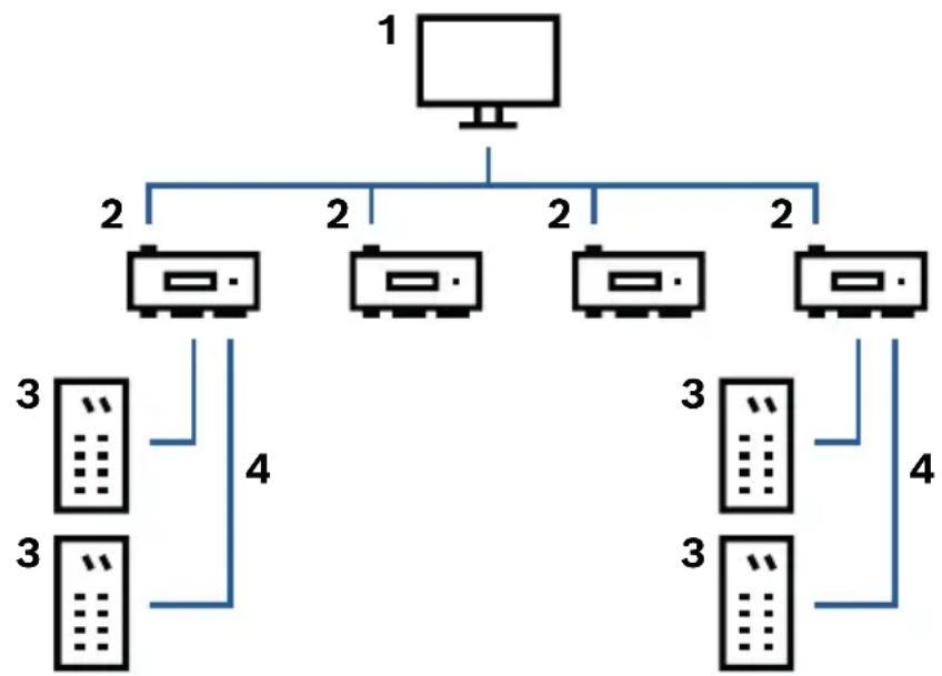
3.3 System overview
The controller is connected to the host system via RS485 or Ethernet, depending on the type of installation. The host interface is selected during installation. The two interfaces are available on the device by default. With RS485 operation, a maximum of eight access controllers can be connected to one party line.
flowchart
graph TD
    A["1"] --> B["2"]
    A --> C["2"]
    A --> D["2"]
    A --> E["2"]
    B --> F["3"]
    B --> G["4"]
    C --> H["3"]
    C --> I["4"]
    D --> J["3"]
    D --> K["4"]
    E --> L["3"]
| 1 Host computer | |
| 2 Access Modular Controller | |
| 3 Card reader | |
| 4 Communication and power supply |
In the communication chain of a system, the access controller is integrated between the host system and the peripheral devices. It is possible to connect up to two readers to the access modular controller.
4 Installing
4.1 Mounting the device on a mounting rail
The controller can be attached on a standard 35 mm (1.377 in.) mounting rail using a snap-in mechanism. Attach the controller into the upper edge of the mounting rail, then push down the device and snap it onto the rail by pushing it towards the back.
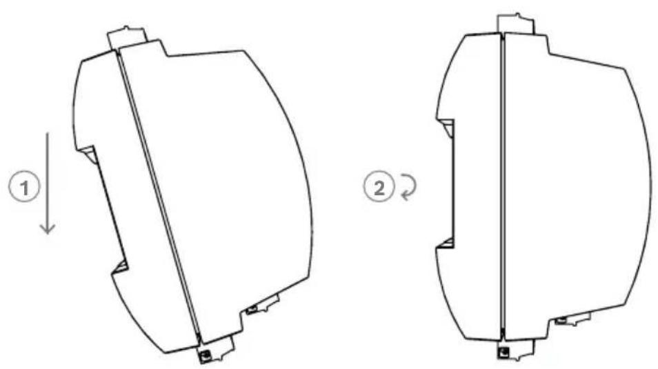
natural_image
Technical line drawings of two mechanical components with directional arrows indicating assembly or motion (no text or symbols)Figure 4.1: Mounting the controller on a mounting rail
4.2 Unmounting the device from a mounting rail

Notice!
To remove the controller from a mounting rail, first remove all pluggable connectors.
Push down the controller until the lower edge snaps out of the mounting rail [1]. Pull the lower end of the controller from the mounting rail [2].
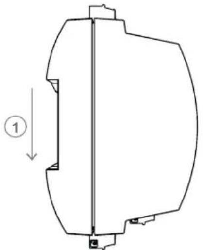
natural_image
Technical line drawing of a mechanical component with no visible text or symbols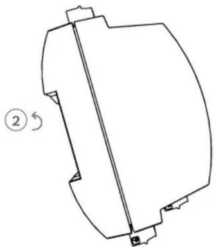
natural_image
Technical line drawing of a mechanical component with no visible text or symbolsFigure 4.2: Unmounting the controller from a mounting rail
4.3 Opening the case

Notice!
To open the controller, first remove all pluggable connectors.
The controller's case consists of a top cover mounted with a two-point snap-in closure on a chassis. To open the case, push down the two snap-ins with a screwdriver, then swing the cover down.
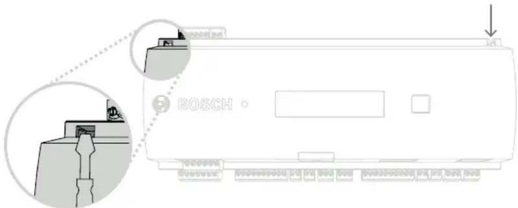
Figure 4.3: Opening the controller's case
4.4 Closing the case
Before aligning the covers, unplug any pluggable screw connectors. Insert the hooks on the lower edge of the front cover into the lugs on lower edge of the plastic back cover [1]. Please ensure that the BOSCH logo is not upside-down. The upper edge of the front cover now aligns with the two-point snap-in closures on the upper edge of the back cover [2], and may thus be clicked gently into place.
Hence the closing process is the reverse of the opening process.
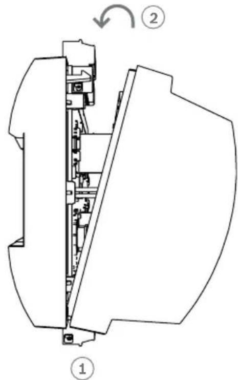
Figure 4.4: Closing the case

Notice!
Risk of damage to equipment
If excessive force is required to close the front cover then it is probably incorrectly hooked into the back cover. In such cases the display dialog button in the front cover will be misaligned and will not function correctly.
4.5 Cabling

Notice!
Risk of malfunction
The cables used in the controller are not prone to electrical interference. However, you should avoid routing cables close to heavy load switching cables and equipment. If this is unavoidable, cross the cable at right angles every 1 to 2 m (3 to 6 ft) to reduce interference.
4.5.1 Conductor data for powering the controller
With the calculation below you can find out which cable type must be used. If you connect the power supply and the controller with the delivered cable set from the enclosure the calculation is not necessary.
For distances below 25 m (75 ft) use AWG18 conductors (1mm ^4 ). For longer distances, install an additional power supply close to the controller.
Please, calculate the voltage drop by checking the conductor specifications for characteristic resistance values. The voltage drop shall not exceed 2 V.
Example:
Length = 100 m/328 ft
$$ U = 1 2 V, \mathrm{I} = 1 \mathrm{A}, \text { maximum } U _ {D r o p} = 2 V $$
$$ i. e. R A W G 1 8 (a c c. s p e c s) = 6. 3 8 5 \frac {\Omega}{1 0 0 0 f t} o r 2 0, 9 4 8 \frac {\Omega}{k m} $$
$$ U _ {D r o p} = 2 0, 9 4 8 \frac {\Omega}{k m} \times 0. 1 k m \times 1 A = 2. 1 V $$
$$ U _ {D r o p} = 6. 3 8 5 \frac {\Omega}{1 0 0 0 f t} \times 3 2 8 f t \times 1 A = 2. 1 V $$
Critical condition! Install the power supply closer to the controller.

Notice!
These specifications apply to power supply, readers, relay outputs, and extension interface.
Regarding inputs, specific voltage-drop values need to be taken into account. Refer to Connecting Analog Input Devices.
4.6 Grounding and shielding
The main grounding point at the controller is connected to pin 2 of the power supply connector - see Connecting Diagrams. It is good practice to shield all wires carrying low level signals.
The controller allows you to create a central ground or shielding point, simply by setting certain jumpers. Set these jumpers only if grounding or shielding is not achieved by other means.

Notice!
Risk of malfunction
Ensure that no ground loops are formed.

Notice!
In general the following apply:
If the devices have their own power supplies, the shielding is applied to one side only. The free end should be insulated to avoid inadvertent connections.
If one device is fed power by another, the cable shielding should be applied to both sides.
4.6.1 Grounding for Host Interface
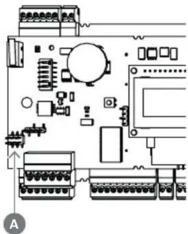
natural_image
Pure electrical circuit lines without any symbols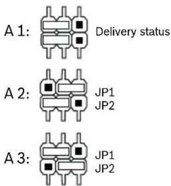
Figure 4.5: Location of ground jumper RS-485 host interface
The internal ground of the controller is always connected with the ground of the RS-485 host.
The jumper setting A1 shows the factory settings.
Jumper JP1 connects the internal ground of the controller to the ground of the RS-485 host interface.
Jumper JP2 manages the signal ground.
Settings for jumper JP1:
If the ground conductor and the shield on the host are not connected and:
- no party line exists, the jumper JP1 is set (= A2)
- a party line exists, the jumper JP1 is set at the first device only (= A2)
Settings for jumper JP2:
If the ground conductor and the shield on the host are not connected and:
- no party line exists, the jumper JP2 is set (= A3)
- a party line exists and signal ground is connected, the jumper JP2 is set at the first device only (= A3)
- a party line exists and signal ground is not connected, the jumper JP2 is set at all devices (= A3)
4.6.2 Grounding for Extension Interface
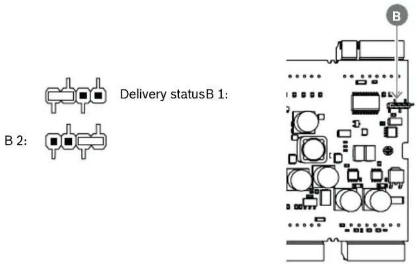
Figure 4.6: Location of ground jumper bottom side
Jumper B connects the internal ground of the controller to the RS-485 ground of the slave interface. Only set jumper B (B2) if the controller powers all other peripheral devices directly connected to it.
4.7 Connecting the power supply to the controller
Connect the power supply to the POWER 7-pin pluggable screw connector.
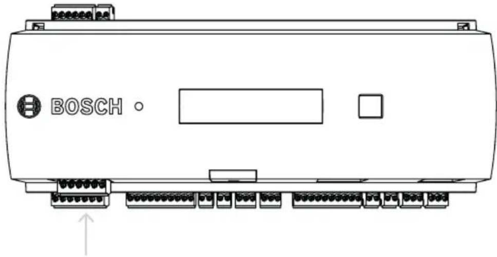
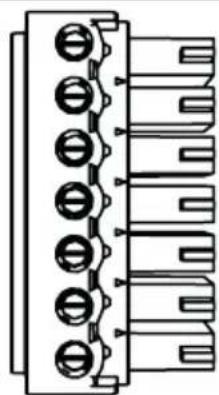
Figure 4.7: Location of the power supply connector
Connect an external power supply (10 - 30 Vdc) for the controller at pin 1 (positive) and pin 3 (0 V) of the pluggable screw connector.
If an uninterruptible power supply (UPS) is used, the relay output for power good signals from the UPS is connected to the following pins:
- pin 4 and 7 for power good AC
- pin 5 and 7 for power good Battery
- pin 6 and 7 for power good DC
Otherwise these pins must be short-circuited.

Notice!
The battery status is checked every 5 minutes by the power supply unit (APS-PBC-60 or APS-PSU-60).
As the battery charging/discharging levels tend to vary, the AMC2 provides information about the battery status every 10 minutes. This feature allows a more reliable battery status information.
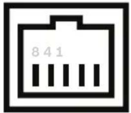
4.8 Ethernet Host Interface
The controller offers a 10/100 Mbit/s Ethernet auto-sensing interface to connect to a local area network or host computer.

Notice!
Use a CAT5 or higher version to connect the controller with the network.
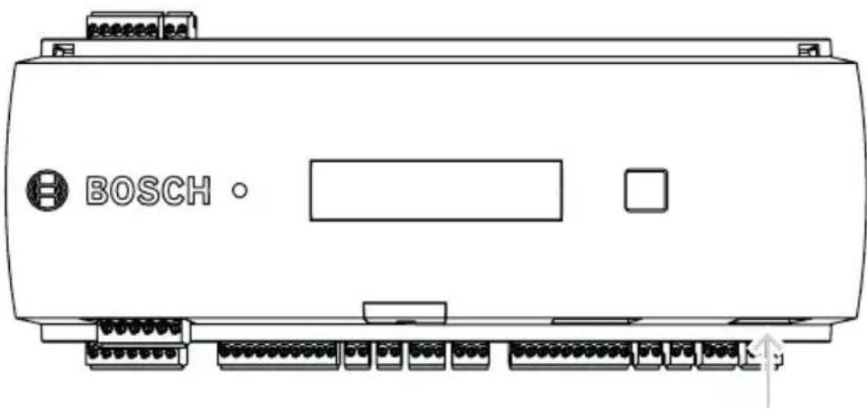
Figure 4.8: Location of the Ethernet interface

Notice!
After connecting a new controller to a network using DHCP, it can take some time before the new controller is recognized by the remote server.
You can accelerate this process by running the following command:
ipconfig /flushdns
This makes the controller immediately available by its name.
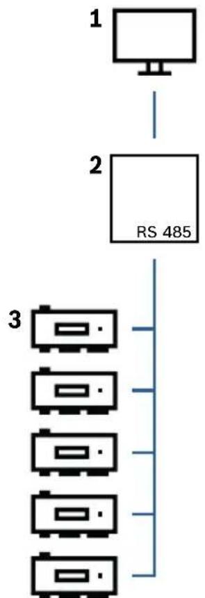
4.9 RS-485 Host Interface
The RS-485 host interface of the controller can be set for using a 2- or 4-wire connection. Up to eight controllers can be used on one host bus.
flowchart
graph TD
    A["1"] --> B["2"]
    B --> C["RS 485"]
    C --> D["3"]
    D --> E["4"]
    E --> F["5"]
    F --> G["6"]
    G --> H["7"]
Figure 4.9: Configuration of a RS-485 host system
| Position | Description |
| 1 Host | |
| 2 RS-485 bus | |
| 3 Access Modular Controller |
The following conditions apply for a RS-485 bus system:
- A bus system consists of a bus line and/or one or more branch lines.
- Cable lengths exceeding 100 m (300 ft) must be installed as bus lines.
-
Branch lines are branching connections from a bus line.
-
Peripheral devices are controllers which are connected to the host computer.
- Maximum cable length of a bus line must not exceed 1200 m (4000 ft).
- The cable length of branch lines must not exceed 100 m (330 ft).
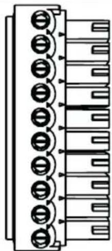
To use RS-485 mode at the controller, connect the data cables to the pluggable screw connector of the RS-485 host interface.
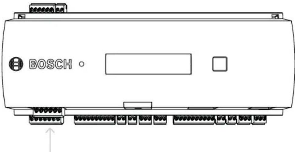
natural_image
Line drawing of a Bosch industrial control panel with terminal connectors and a labeled port (no text or symbols beyond branding)Figure 4.10: RS-485 host interface
5 Operating
5.1 Configuring Ethernet interface
To configure the controller in a TCP/IP network environment, use the AmclpConfig tool. It is located in a directory on the standalone or the remote server of the BIS:
\\Runtime-drive:\MgtS\AccessEngine\AC\bin
and in the Program Folder of the Access PE:
Start > Programs > Access Personal Edition > AmclpConfig
This tool can be copied and used on every computer on the network.
Consult the online help of the AmclpConfig for details on configuring the controller.
To ensure that the controller can communicate with the software follow these naming rules:
- Use only alphanumeric characters plus the separator "-" (minus/dash).
- Do not use special characters or spaces.
- The network name must start with a letter.
- The names are not case sensitive.
6 Troubleshooting
If problems occur read the table below.
Adjust only those controls specified in the installation manual.
Improper adjustment of other controls may result in damage, and require extensive work by a qualified technician to restore the unit to normal operation.
If you are unsure of the problem or if the problem persists, contact After sales support, page 34.
Problem Cause Solution
Display is not working.
- Voltage is too low.
- Power is off.
- Make sure the power supply has enough voltage to power the controller.
- Power up the controller.
Controller is not online.
- Network connection is missing.
- DIL switch 5 is set to OFF (BPA protocol is selected).
- Plug the Ethernet cable into the controller.
- Make sure to configure the Ethernet interface correctly. Refer to Configuring the Ethernet Interface for instructions.
| Problem Cause Solution | ||
| - Set DIL switch5 to ON (SDEB protocol is selected). | ||
| Controller does not work as expected. | - Switch the power of the controller off and on again.- Check the configuration of the controller.If necessary, delete all configuration data by Resetting the Device to Factory Default.- Reset the controller as described in Resetting the software, page 32. |
6.1 Resetting the software
- Insert the provided screwdriver into the hole until it reaches the reset button as shown in the figure below.
- Press the reset button for at least three seconds.
- The controller deletes its application program leaving only its bootloader and network setting.
As soon as it is online again, controller's bootloader will download a fresh copy of the application program and configuration. If the problem persists contact after sales support.
6.2 Resetting the device to factory default
- Reset the controller as described in Resetting the software, page 32.
- Open the upper case of the controller as described in Opening the Case.
- Set all six DIL switches of the RS-485 selector to ON as shown in the figure below.
-
Press the reset button on the board.
-
Set the DIL switches back in the address state before resetting.
The controller now has the following network configuration:
- DHCP = 1
- IP = [assigned by DHCP server or "0.0.0.0" if not available]
- Subnet mask = [assigned by DHCP server or "0.0.0.0" if not available]
- Password = no password - Create your password in the IP Config settings of the AMC.
7 Service and repair
The controller is backed by a standard warranty of 3 years.
Contact your dealer to buy a warranty extension.
Warning!

Risk of electric shock
Opening or removing the covers can expose you to dangerous voltages. An electric shock can cause injuries or death. Do not perform servicing tasks yourself. Refer all servicing to qualified service personnel.
Damage that requires service
Disconnect the controller from the main AC or DC power source and refer servicing to qualified service personnel under the following conditions:
- If the power supply cord or plug is damaged.
- If liquid has been spilled or an object has fallen into the controller.
- If the controller has been exposed to water and/or humid weather (rain, snow, etc.).
- If the controller has been dropped or the cabinet damaged.
- If the controller shows a distinct change in performance.
Safety check
Upon completion of service or repair work on the controller, ask the service technician to perform safety checks to ensure that the controller operates properly.
After sales support
For more information, visit https://www.boschsecurity.com/xc/en/support/.
8 Disposal
Electrical and electronic waste

natural_image
Simple line drawing of a trash bin with two crossed lines indicating no waste or restriction (no text or symbols)
This product and/or battery must be discarded separately from household waste. Discard this product according to local laws and regulations, to allow its reuse and/or recycling. This will help in conserving resources, and in protecting human health and the environment.
9 Technical specifications
Mechanical
| Type DIN rail mounting | |
| Housing material ABS and Polycarbonate(UL94V-0) | |
| Dimensions (H × W × D) 232 mm × 90 mm × 63 mm(9.13 in. × 3.54 in. × 2.48 in.) | |
| Weight 503 g | |
| Color White | |
System specifications
| Memory - Serial EEPROM | - Pluggable 2 GB compact flash |
| Reader interfaces - 2× Wiegand | |
| Host interface - RJ45 for TCP IP | communication- RS485 |
| Outputs - 4× relay outputs | - 30 V DC max. (switching voltage)- 1,25 A max. (switching current) @ 30Vdc |
| Inputs 4× 4-State inputs | |
| Tamper switch 2-wire | |
| Reset button Yes | |
| Power | - 10 VDC to 30 VDC- 60 VA max.-55 VA (available for external devices) |
| Display LCD |
Environmental
| Temperature 0 °C to +50 °C (32 °F) | °F to 122 °F) |
| Environmental rating IP 30 | |
| RoHS Compliant |

Notice!
To determine the environmental impact of an installation, take the most extreme values of all participating devices into account.

Notice!
To determine the vulnerability of an installation, take the most restrictive values of all participating devices into account.
Access Modular Controller Series
| Hazardous substance table according to SJ/T 11364-2014 | ||||||
| Pb(Pb) | Hg(Hg) | Cd(Cd) | Cr6+(Cr6+) | PBB(PBB) | PBDE(PBDE) | |
| Housing & enclosures | ○ ○ ○ | ○ ○ | ○ | |||
| PCBA X X ○ ○ ○ | ○ | |||||
| Connectors X ○ ○ ○ | ○ ○ | |||||
| Electroniccomponents | X ○ | ○ ○ | ○ ○ | |||
| Plastic materials ○ ○ | ○ ○ | ○ ○ | ||||
| Metal materials ○ ○ | ○ ○ | ○ ○ | ||||
| This table was created according to the provisions of SJ/T 11364 | ||||||
| ○: The content of such hazardous substance in all homogeneous materials of such component is below the limit defined in GB/T 26572 | ||||||
| x: The content of such hazardous substance in a certain homogeneous material is above the limit defined in GB/T 26572 | ||||||

Notice!
The voltage drop from the power supply to the controller affects the interfaces of the controller. The total drop must not exceed 2V.
10 Appendices
10.1 Connecting diagrams
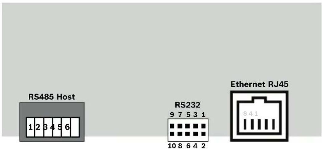
Figure 10.1: Connectors on upper PCB
| 1 Shield | |
| 2 Data RxTx+ (2-wire) Data Rx+ (4-wire) | |
| 3 Data RxTx- (2-wire) Data Rx- (4-wire) | |
| 4 Ground (PAG) | |
| 5 Data Tx+ (4-wire) | |
| 6 Data Tx- (4-wire) | |
 | 1 TXD+ |
| 2 TXD- | |
| 3 RXD+ | |
| 4 Not connected | |
| 5 Not connected | |
| 6 RXD- | |
| 7 Not connected | |
| 8 Not connected |
Tab. 10.1: RS-485 host on upper PCB
Tab. 10.2: Ethernet Network socket (RJ45)
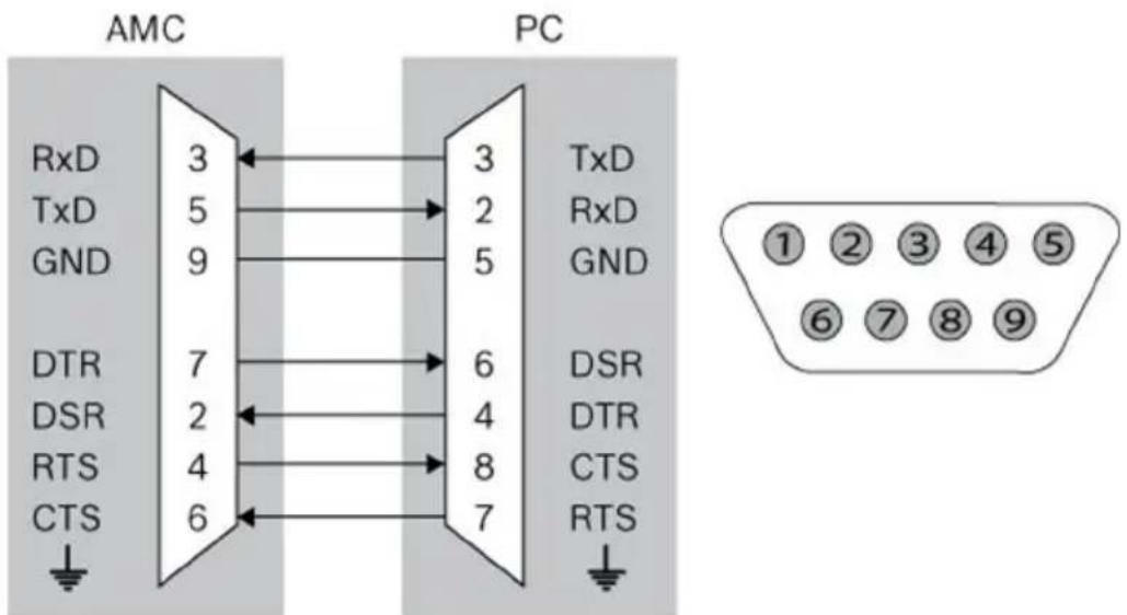
Figure 10.2: Interconnect diagram of the RS-232 serial interface
flowchart
graph TD
    A["Power Supply"] --> B["Power Supply"]
    A --> C["UPS"]
    B --> D["Reader Interface 1"]
    C --> D
    D --> E["Analog Input 1"]
    D --> F["Analog Input 2"]
    D --> G["Relay Output 1"]
    D --> H["Relay Output 2"]
    D --> I["Reader Interface 2"]
    I --> J["Analog Input 3"]
    I --> K["Analog Input 4"]
    I --> L["Relay Output 3"]
    I --> M["Relay Output 4"]
    B --> N["S1"]
    C --> O["S2"]
    D --> P["S3"]
    E --> Q["S4"]
    F --> R["S5"]
    G --> S["S6"]
    H --> T["S7"]
    I --> U["S8"]
    J --> V["S9"]
    K --> W["S10"]
    L --> X["S11"]
    M --> Y["S12"]
    N --> Z["S13"]
    O --> AA["S14"]
    P --> AB["S15"]
    Q --> AC["S16"]
    R --> AD["S17"]
    S --> AE["S18"]
    T --> AF["S19"]
    U --> AG["S20"]
    V --> AH["S21"]
    W --> AI["S22"]
    X --> AJ["S23"]
    Y --> AK["S24"]
    Z --> AL["S25"]
    AA --> AM["S26"]
    AB --> AN["S27"]
    AC --> AO["S28"]
    AD --> AP["S29"]
    AE --> AQ["S30"]
    AF --> AR["S31"]
    AG --> AS["S32"]
    AH --> AT["S33"]
    AI --> AU["S34"]
    AJ --> AV["S35"]
    AK --> AW["S36"]
    AL --> AX["S37"]
    AM --> AY["S38"]
    AN --> AZ["S39"]
    AO --> BA["S40"]
    AP --> BB["S41"]
    AQ --> BC["S42"]
    AR --> BD["S43"]
    AS --> BE["S44"]
    AT --> BF["S45"]
    AU --> BG["S46"]
    AV --> BH["S47"]
    AW --> BI["S48"]
    AX --> BJ["S49"]
    AY --> BK["S50"]
    AZ --> BL["S51"]
    BA --> BM["S52"]
    BB --> BN["S53"]
    BC --> BO["S54"]
    AD --> BP["S55"]
    AE --> BQ["S56"]
    AF --> BR["S57"]
    AG --> BS["S58"]
    AH --> BT["S59"]
    AI --> BU["S60"]
    AJ --> BV["S61"]
    AK --> BW["S62"]
    AL --> BX["S63"]
    AM --> BY["S64"]
    AN --> BZ["S65"]
    AO --> CA["S66"]
    AP --> CB["S67"]
    AQ --> CC["S68"]
    AR --> CD["S69"]
    AS --> DD["S70"]
    AT --> DE["S71"]
    AU --> DF["S72"]
    AV --> DG["S73"]
    AW --> DH["S74"]
    AX --> DI["S75"]
    AY --> DJ["S76"]
    AZ --> DK["S77"]
    BA --> DL["S78"]
    BB --> DV["S79"]
    AC --> DW["S80"]
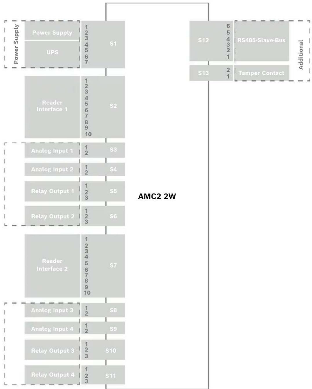
Figure 10.3: Connector blocks of the AMC2-2W
 | 1 Power supply, DC positive (10V - 30V) |
| 2 Shield | |
| 3 Power supply (0V) | |
| 4 UPS (power good signal) - AC | |
| 5 UPS (power good signal) - Battery | |
| 6 UPS (power good signal) - DC | |
| 7 UPS (power good signal) - Common |
Tab. 10.3: Power supply
 | 1 red Reader Supply (12V) |
| 2 black Reader Supply (0V) | |
| 3 green Data 0 | |
| 4 white Data 1 | |
| 5 drain Shield | |
| 6 orange green LED | |
| 7 brown red LED | |
| 8 yellow Beeper | |
| 9 blue Hold | |
| 10 violet Card Present |
Tab. 10.4: Wiegand interface AMC

Notice!
For reader settings refer to the respective reader manual.
| 1 Analog Input, in | |
| 2 Analog Input, out |
Tab. 10.5: Analog input
| 1 Relay Output, normally open | |
| 2 Relay Output, common | |
| 3 Relay Output, normally closed |
Tab. 10.6: Relay output
| 1 Power supply for external devices (10V - 30V) | |
| 2 Power supply for external devices (0V) | |
| 3 Shield | |
| 4 Data RxTx+ | |
| 5 Data RxTx- | |
| 6 Ground (PAG) |
Tab. 10.7: Host / Extension interface
| 1 Tamper Contact, in | |
| 2 Tamper Contact, out |
Tab. 10.8: External tamper contact
Bosch Security Systems B.V.
Torenallee 49
5617 BA Eindhoven
Netherlands
www.boschsecurity.com
© Bosch Security Systems B.V., 2019