
KP7 - Regulator Niles - Free user manual and instructions
Find the device manual for free KP7 Niles in PDF.


| Product Type | 7-Button Keypad Regulator |
| Brand | Niles |
| Model | KP7 |
| Dimensions | 4.12" x 1.75" x 1.24" (104.65 mm x 44.45 mm x 31.5 mm) |
| Mounting Depth | 1.75" (4.5 cm) |
| Buttons | 5 individually capped, 2 shared for rocker capping |
| LED Backlight | 5 individually controlled white (buttons 1-5), 2 shared white (rocker) |
| Network | 10/100/1000 Ethernet |
| Connection | LAN/PoE RJ-45 |
| Power Requirements | PoE IEEE 802.3at, 13W max draw (@48V, 270 mA max) |
| Box Contents | 1 KP7 keypad, 2 mounting screws, 10 alternate key caps, Quick Install Guide |
| Mounting Box | Standard 1-gang box, 20 cu in or larger |
| Trim Plate | Decorator-style opening wall plate (not included) |
| Color | White standard; optional black (KP7BK-B) or light almond (KP7BK-LA) bezel kit |
| Customization | Changeable buttons and bezel; custom engraveable buttons available |
| Compliance | FCC Part 15 Class B, Canadian ICES-003 |
| Intended Use | Indoor, low-humidity environments only |
| Application | Control of Niles Auriel MRC-6430 multi-room audio system (and compatible controllers) |
| Key Features | 4 favorite channels, volume up/down, system/zone off, plug-and-play with Auriel software |
| Warranty | Refer to manufacturer for details |
Frequently Asked Questions - KP7 Niles
User questions about KP7 Niles
0 question about this device. Answer the ones you know or ask your own.
Ask a new question about this device
Download the instructions for your Regulator in PDF format for free! Find your manual KP7 - Niles and take your electronic device back in hand. On this page are published all the documents necessary for the use of your device. KP7 by Niles.
USER MANUAL KP7 Niles
natural_image
Abstract grayscale wave pattern with curved lines and a circular element (no text or symbols)KP7 – Keypad Quick Install Guide
English
Thank you for including the KP7, 7 button keypad, as part of the user interface strategy for your customer. The KP7 has been designed to provide years of trouble free operation when wired and installed properly. The KP7 has been designed for installation in low humidity environments and should never be installed outdoors or in high humidity areas.
Included in the box
- 1ea KP7 keypad
• 10ea Alternate key caps - 2ea Mounting screws
• 1ea Quick Install Guide (this document)
Introduction
To install the KP7 you will need a standard 1 gang box rated for 20 cu. in. or more.
Specifications
Dimensions 4.12" x 1.75" x 1.24"
104.65 mm x 44.45 mm
X
31.5
mm
Buttons 5 individually capped
2 shared for rocker capping
LED 5 individually controlled white
2 shared control white
Network
10/100/1000
Connections
LAN/PoE
RJ-45
Power Requirements
PoE IEEE 802.3at,
13
W
maximum
draw
(@48V / 270 mA max.)
=
Important Safety Instructions
- Read these instructions.
- Keep these instructions.
- Heed all warnings.
- Follow all instructions.
- Do not use this apparatus near water.
- Clean only with dry cloth.
- Install in accordance with the manufacturer's instructions.
- Do not install near any heat sources such as radiators, heat registers, stoves or other apparatus (including amplifiers) that produce heat.
- Only use attachments/accessories specified by the manufacturer.
- Refer all servicing to qualified service personnel. Servicing is required when the apparatus has been damaged in any way such as power-supply cord or plug is damaged, liquid has been spilled or objects have fallen into the apparatus, the apparatus has been exposed to rain or moisture, does not operate normally, or has been dropped.
FCC and IC Information:
This Class B digital apparatus complies with Part 15 of the FCC rules and with Canadian ICES-003. Operation is subject to the following two conditions: (1) This device may not cause interference and (2) This device must accept any interference, including interference that may cause undesired operation of the device.
This equipment has been tested and found to comply with the limits for a Class B digital device, pursuant to part 15 of the FCC Rules.
These limits are designed to provide reasonable protection against harmful interference in a residential installation. This equipment generates, uses and can radiate radio frequency energy and, if not installed and used in accordance with the instructions, may cause harmful interference to radio communications. However, there is no guarantee that interference will not occur in a particular installation.
If this equipment does cause harmful interference to radio or television reception, which can be determined by turning the equipment off and on, the user is encouraged to try to correct the interference by one or more of the following measures:
- Reorient or relocate the receiving antenna.
- Increase the separation between the equipment and receiver.
- Connect the equipment into an outlet on a circuit different from that to which the receiver is connected.
- Consult the dealer or an experienced radio/ TV technician for help.
Warning: Changes or modifications to this unit not expressly approved by the party responsible for compliance could void the user's authority to operate the equipment.
KP7 - Overview
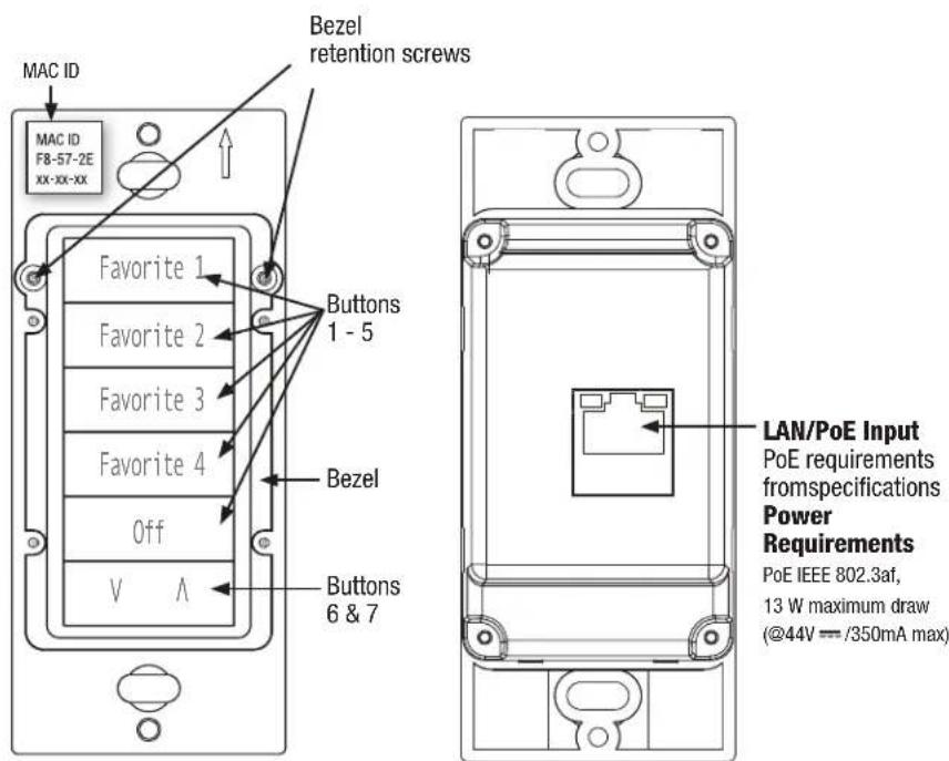
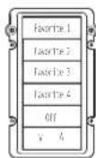
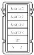
Front Back
Planning the installation
1
The KP7 mounts in a 1 gang (US) box. It is suggested that it be placed near light switches to reduce wall clutter. The KP7 trims with a standard decorator-style opening wall plate (not included).
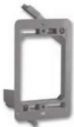
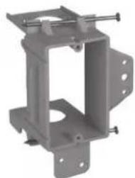
The KP7 requires a mounting depth of at least 1 34 " (4.5cm) and it is recommended that a 20cu in or larger switch box or a 1 gang low voltage bracket be used. The KP7 will gang with other low voltage devices utilizing a standard decorator-style trim plate.
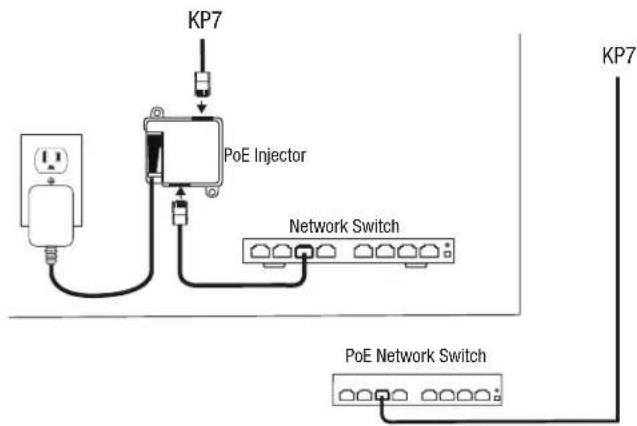
The KP7 requires connection to a PoE, Power over Ethernet, switch or to an Ethernet cable connected to a PoE injector. The KP7 cannot be locally powered.
Installing the KP7
2
Mounting Location
The KP7 should be located high enough that your customer will be able to read the buttons. Generally mounting next to, above, or below a light switch is appropriate.
Light Switch
Potential Mounting Locations
Mounting Box
The KP7 was designed to fit comfortably in a Carlon 70998 (new construction) or B120R (old work) 20 cu in junction box or virtually any low voltage bracket. If you plan to use a different brand box please verify that the KP7 will fit without issue.
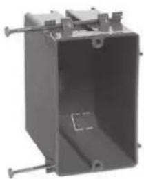
natural_image
Exterior view of a rectangular metal enclosure with mounting feet and internal structure (no text or symbols visible)20 cu. in. New Const. Junction Box
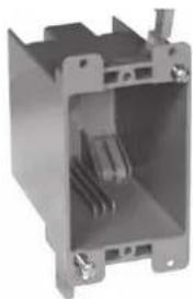
natural_image
Exterior view of a gray industrial enclosure or housing unit with internal cooling fins and mounting brackets (no visible text or symbols)20 cu. in. Old Work Junction box
natural_image
3D rendering of a gray metal bracket with mounting holes and mounting feet (no text or symbols)Old Work L.V. Bracket New Const. L.V. Bracket
3
Changing buttons and changing color
The KP7 may accommodate changes to the buttons or to the overall color.
The steps for both are very similar.
Button changes – White pre-engraved buttons are included for some installations.
A total of 16 buttons are included with the unit.
Color Changes - Light Almond (KP7BK-LA) and Black (KP7BK-B)
color change kits are available (sold separately).
Custom buttons in all three colors are available. See your Rep or Distributor for details.
To change buttons or colors:
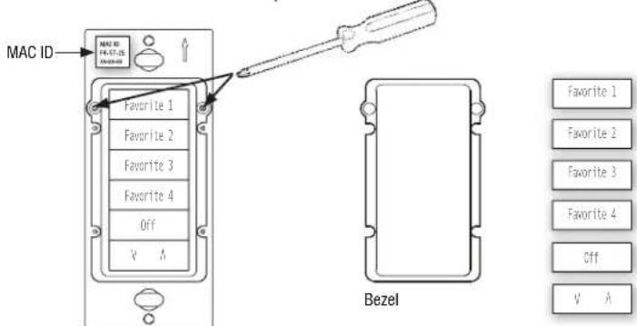
Remove the two small Phillips head screws holding the bezel in place and remove the bezel.
Replace buttons and bezel as necessary based on your installation programmed requirements.
Re-install the two small Phillips head screws.
4
Connecting the KP7
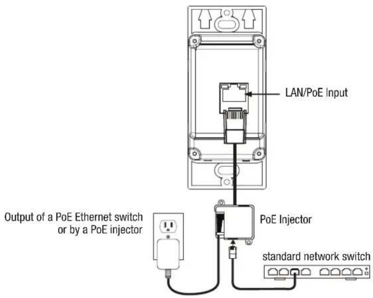
The KP7 is powered by the output of a PoE Ethernet switch or by a PoE injector.
The KP7 cannot be directly powered by a power supply. If you have terminated the CAT-5 wiring be sure to continuity test the wire before connecting the KP7. Insert the RJ-45 connector into
the receptacle on the rear of the KP 7 and listen for the tab to click.
Give the wire a light tug to verify the connector is secure.
Mounting the KP7
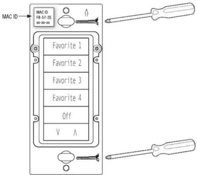
Being careful not to pinch the CAT5 wire, slide the KP7 into the box and secure with the included screws. The KP7 fits a standard decorator-style opening and is gangable with other low voltage decorator-style devices. Note the MAC ID of the KP7 on your System Worksheet to assist with programming completion.
Connecting the KP7 to your controller
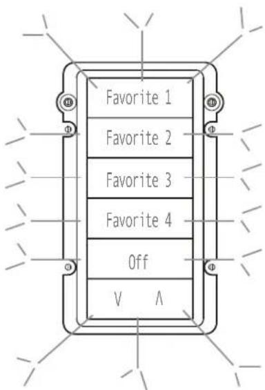
The backlights on the KP7 will flash when the device is powered up but not connected to a controller. Once the KP7 is connected to a controller, the controller will assign default or programmed LED levels. Refer to the training documentation for your controller on how to program the KP7.
HOME OF ENTERTAINMENT INNOVATION
Niles Auriel Control System
for the Next-Gen Home Installation
Introducing the Niles Auriel nKP7, a 7-button, state-of-the-art keypad designed to allow simple control of the Niles Auriel™ MRC-6430 multi-room audio control system.
The Auriel nKP7 7-button keypad delivers a simple interface that enables the end user to select favorite sources, adjust volume and turn off the system—all at the touch of a button.
For Niles Auriel MRC-6430 users, the keypad provides simple preset access to preferred content on four channels, plus the ability to raise and lower the volume and power down a zone or the system.
The keypad features interchangeable buttons, two of which offer a "rocker" style action that delivers volume adjustment control while the other five buttons are single action.
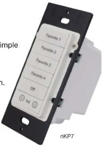
This next-gen keypad is simple to use, easy to navigate with the backlit pad, and the decor style of the keypad allows it to be placed in multiple gang decorator plate applications with lighting and intercom systems.
FEATURES:
- 7-button backlit keypad
- Four favorite channels plus volume up and down control, system & all zones off
- PoE for single wire hookup
- No programming required – plug and play operation with Niles Auriel Software
- Custom engraveable buttons
• Gangable with any 1g device - Comes in white with optional black or light almond bezel kit
SPECIFICATIONS:
| Dimensions 4.12" x 1.75" x 1.24" | |
| Mounting Depth 1.75" | |
| Button type • Contact type buttons | 5 individually capped2 shared for rocker capping5 individually controlled white LEDs for backlighting2 shared control white LEDs for backlighting0/100/1000 Ethernet |
| Connections LAN/ PoE RJ-45 | |
| Power Requirements PoE (Power over Ethernet) EEE802.3at, 13w maximum draw(@48 V== 270mA max) | |
Note: Decorator trim plate not included


NILES®
- KP7 – Keypad Quick Install Guide
- English
- Included in the box
- Introduction
- Specifications
- Important Safety Instructions
- FCC and IC Information:
- Planning the installation
- Installing the KP7
- Mounting Location
- Mounting Box
- 3
- Changing buttons and changing color
- To change buttons or colors:
- 4
- Connecting the KP7
- Mounting the KP7
- Connecting the KP7 to your controller
- Niles Auriel Control System
- for the Next-Gen Home Installation
- FEATURES:
- NILES®
Brand : Niles
Model : KP7
Category : Regulator