
UCR411A - Receiver Lectrosonics - Free user manual and instructions
Find the device manual for free UCR411A Lectrosonics in PDF.


| Product Type | Digital Hybrid Wireless Compact UHF Receiver |
| Brand | Lectrosonics |
| Model | UCR411A |
| Frequency Range | Available in multiple blocks: 470.100-495.600 MHz (Block 470) to 844.800-861.900 MHz (Block 33) |
| Receiver Type | Triple conversion superheterodyne with 244 MHz, 10.7 MHz, and 300 kHz IFs |
| Sensitivity | 0.9 µV (-108 dBm) for 20 dB SINAD, A-weighted; 1.12 µV (-105 dBm) for 60 dB quieting |
| Audio Output | Adjustable from -50 dBu to +5 dBu in 1 dB steps; balanced XLR (pin 2 hot) |
| Power Options | Two 9V alkaline or lithium batteries; external DC 10-18 V (center positive) |
| Battery Life | 6-8 hours continuous (alkaline); up to 20 hours (lithium) |
| Dimensions | 3.23" x 1.25" x 4.64" (82 x 32 x 118 mm) |
| Weight | 14 oz (397 g) with batteries |
| Key Technologies | Digital Hybrid Wireless, SmartDiversity, SmartNR, DSP pilot tone, supersonic noise-based filter |
| Compatibility Modes | 400 Series, 200 Series, 100 Series, IFB, Modes 3, 6, 7 (NA and EU versions) |
| Frequency Tuning | 256 frequencies per block in 100 kHz steps; normal and group tuning (preset groups A-D, user groups U-V) |
| Scanning Mode | Built-in spectrum analyzer with coarse and fine views for interference detection |
| Audio Performance (400 Series) | Frequency response 32 Hz-20 kHz (±1 dB); THD 0.2% typical; SNR up to 113 dB (SmartNR FULL with limiting) |
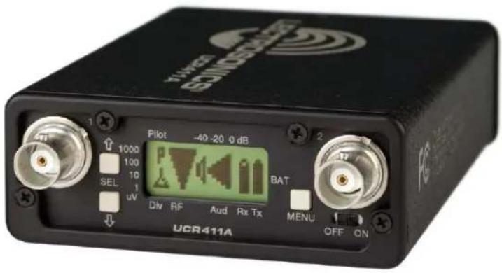
| Front Panel Controls | MENU button, SELECT Up/Down buttons, power switch; LCD with main, frequency, battery, and setup windows |
| Pilot Tone | DSP-generated ultrasonic pilot tone; bypassable for diagnostics |
| Antenna Inputs | Dual BNC female, 50 Ohm impedance |
| Accessories Included | Two BNC whip antennas (A8U), Velcro mounting strips, power cable (coaxial to stripped leads) |
Frequently Asked Questions - UCR411A Lectrosonics
User questions about UCR411A Lectrosonics
0 question about this device. Answer the ones you know or ask your own.
Ask a new question about this device
Download the instructions for your Receiver in PDF format for free! Find your manual UCR411A - Lectrosonics and take your electronic device back in hand. On this page are published all the documents necessary for the use of your device. UCR411A by Lectrosonics.
USER MANUAL UCR411A Lectrosonics
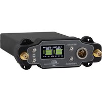
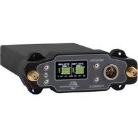
Digital Hybrid Wireless® Compact UHF Receiver
(US patent 7,225,135)
CE1313 Ⓞ
Fill in for your records:
Serial Number:
Purchase Date:

Opinion Number: R1112093
DIRECTIVE 1999/5/EC
NOTIFIED BODY STATEMENT OF OPINION
Bay Area Compliance Laboratories Corp.
| Date of issue: | 2012-02-18 |
| Applicant Details: | Lectromeries, Inc.581 Laser Road, Rio Rancho, NM 87124, USA |
| Trade Name/Model: | UCB411A |
| Equipment Type: | Digital Hybrid UHF Receiver |
| Serial Number: | J753/0 |
| Network Interface: | N/A |
| Frequency Range: | Band e1: 470.1-495.6 MHz, Band c: 803-805 MHzBand e1: 665.6-691.1 MHz, Band e2: 786-789 MHzBand e3: 825-826 MHz, Band e4: 826-832 MHz |
| Channel Spacing: | Bandx e3 and e4: 200 kHz |
| RF Output Power: | None |
| Modulation Type: | FM |
| Antenna Type: | Monopole, omnidirectional |
| Notified Body 1513: | Bay Area Compliance Laboratories Corp.1274 Annilwood Ave., Sanzyvale, CA 9409, USATel (408) 732-9162 Fax (408) 732-9164www.bacorp.com |
| Essential Requirements | Specifications / Standards | Document Identification | Result |
| Radio Spectrum, Article 3(2) | EN 300-422-2 V 1.2.2 (208-03) | R1112093-422 | Compliant |
| EMC, Article 3(1)(b) | EN 301-489-9 V 1.4.1 (207-11) | R1112093-12 | Compliant |
| Safety, Article 3(1)(a) | EN 60950-1: 2006 + A1: 2010 | R1112093-3 | Compliant |
Our opinion in accordance with Council Directive 1991/SEC on Radio equipment and
Telecommunications terminal equipment of the devices covered therein and mutual recognition of their conformity in that the apparatus identified above complies with the requirements of that directive stated above.
Marking: It is recommended that the product has the U.F. must, the nominal body number or as digital to the right only when all the essential requirements have been met and a Manufacturer's Declaration of Confidential (3N 05014) has been filed with the European Commission.
CE1313①
Number of Annexes to this statement: 1
Authorized by: John Chan, Technical Expert
Bay Area Compliance Laboratories Corp. 1274 Anvilwood Ave, Sunnyvale, CA 94089, U.S.A. Tel: (400)732-9162 Fax: (408)732-9164

- Marcha, 2017 - 8/17 - 1/54 (20)3602-4501 - Fax(030)802-6393 m: www.assw@reetservice.com
20 February 2012
CE - Declaration of Conformity
We. Lectrosanios Inc.
581 Laser Road NE
Rio Rancho, New Mexico 87124 USA
declare under our sole responsibility that the product
UCR411A
to which this declaration relates is in conformity with the following standards:
EN 300 422-2 V1.2.2 (2008-03)
EN 301 489-9 V1.4.1 (2007-11)
EN 60950-1:2006+A1:2010
Test report no. R1112093-422-1
Date of test report: 20 January 2012
Test report no. R1112093-12-1
Date of test report: 20 January 2012
Test report no. R1112093-3
Date of test report: 30 January 2012
Robert Leanning
Robert Cunnings
V.P. Engineering
Lectrosonics, Inc.
Digital Hybrid Wireless®
The Lectrosonics Digital Hybrid Wireless ^™ uses innovative technology to combine the new advantages of digital audio with the classic advantages of analog RF transmission, thus delivering the superior sound quality of a digital system and the excellent range of an analog system. A proprietary algorithm encodes the digital audio information into an analog format which can be transmitted in a robust manner over an analog FM wireless link. The receiver employs state-of-the-art filters, RF amplifiers, mixers and detector to capture the encoded signal and a DSP recovers the original digital audio.
This digital/analog hybrid technique has some very beneficial properties. Because the information being transmit-
ted is digitally encoded, immunity to noise is much higher than a compandor can offer. Because the encoded audio is sent in analog format, spectral and power efficiency and operating range are not compromised.
Unlike traditional analog compandor systems, no artifacts are introduced under strong RF conditions.
Under weak RF conditions, the received signal degrades gracefully, like an analog system, delivering as much usable audio as possible at maximum range. Since the audio is free of compandor artifacts, pumping and breathing problems are also greatly reduced.
(*US Patent 7,225,135)
Table of Contents
Digital Hybrid Wireless® 3
General Technical Description ....6
Compatibility Modes....6
Diversity Reception....6
RF Frequency Tracking Front-End and Mixer 6
Microcontroller, PLL and VCO Circuits....6
IF Amplifiers and SAW Filters 7
Digital Pulse Counting Detector....7
DSP-Based Pilot Tone....7
Supersonic Noise-Based
Dynamic Filter and SmartSquelch™ 7
Smart Noise Reduction (SmartNR ^™ ) 7
Audio Output Level....8
Test Tone....8
Batteries....8
Power Supply 8
LCD Display 8
Power Off 8
Front Panel Controls and Functions....9
LCD Screen 9
MENU Button....9
SELECT Up/Down Buttons....9
Power ON/OFF Switch....9
Rear Panel Features....9
XLR Audio Output Jack....9
Power Input Jack....9
Main Window (LCD) 10
Menu Selections from Main Window....11
Frequency Window....11
Battery Level Window 11
SETUP Window 12
LEVEL Setup Screen....12
TONE Setup Screen 12
TXBAT Setup Screen....12
PHASE Setup Screen....12
SmartNR Setup Screen 12
TUNING Setup Screen 13
COMPAT Setup Screen....13
Frequency Scan Mode ....14
Scan & VIEW WINDOW Elements....14
Fine VIEW WINDOW Elements ....14
Antenna Use and Placement....15
Installation and Operating Instructions....16
Finding Clear Frequencies....16
Locking and Unlocking the
UCR411A Front Panel Controls 17
Replacing the Batteries....18
Antenna/Block Reference Table 19
Pre-coordinated Frequencies....20
Diagnostics 21
Multi-channel System Checkout....21
Pilot Tone Bypass....21
Replacement Parts and Accessories....22
Troubleshooting....23
Specifications and Features....25
Service and Repair 26
Returning Units for Repair 26
General Technical Description
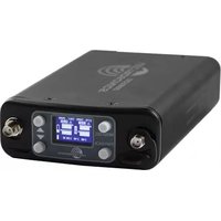
The UCR411A is a portable, high performance, triple-conversion, frequency synthesized, UHF receiver fully compatible with all Lectrosonics 400 Series transmitters (and some other transmitter types – see Compatibility Modes for details). The RF performance is extremely stable over a very wide temperature range, making the UCR411A perfectly suited to the rough environmental conditions found in the field. The proprietary audio processing includes a digital signal processor for very low distortion and a superior signal-to-noise ratio.
The UCR411A front panel features a menu-driven LCD graphic display and three control buttons to conveniently view and alter user settings. The main window, for example, displays the pilot tone indicator, antenna diversity phase, RF level, audio level, receiver battery status and transmitter battery status. It is also possible to bypass the pilot tone/squelch from the main display window. Other windows display operating frequency, audio output level, battery voltage and test tone status. The frequency scan mode provides a spectrum analyzer for a graphical means of observing all signals "on the air" within the frequency range of the receiver in order to find operating frequencies that are free of interference.
Compatibility Modes
The UCR411A receiver was designed to operate with Lectrosonics 400 Series transmitters and will yield the best performance when doing so. Due to the flexibility of digital signal processing, the UCR411A is also able to operate with Lectrosonics 200 Series, Lectrosonics 100 Series, IFB Mode, as well as Modes 3 and 6, which work with certain non-Lectrosonics transmitters.
Diversity Reception
The UCR411A technology with SMARTDiversity™ minimizes dropouts in situations where multi-path reflections can cause serious problems. The phase diversity network and PIN diode RF switches are controlled by
the microprocessor using a sophisticated algorithm to use both antennas simultaneously. This design keeps the receiver compact enough for camera mounting or shoulder bag applications, yet provides effective diversity reception.
RF Frequency Tracking Front-End and Mixer
The receiver is frequency agile and can be set to operate on any one of 256 frequencies within its tuning range. To significantly reduce unwanted interference and intermodulation problems, the UCR411A has a frequency selective front-end section that tracks and tunes to the desired signal frequency and rejects or "tunes out" unwanted interfering signals. The design consists of four varactor tuned ceramic transmission line resonators controlled by the microprocessor to provide good selectivity. The low noise high current RF amplifier was designed with feedback regulation for stability and precise gain in order to handle stronger RF signals without output overload. The first mixer is of new GaAs technology that has a very high third order intercept point. This produces a robust front-end that is as selective as fixed single frequency designs and is suitable for use in close proximity to other receivers and transmitters commonly used in field production "bag" systems.
Microcontroller, PLL and VCO Circuits
The 8-bit microcontroller is truly the “heart” of the UCR411A receiver. It monitors user command inputs from the front panel control buttons and numerous other internal signals such as RF level, audio levels, pilot tone levels and external/internal power voltages. Outputs from the microcontroller drive the LCD display and backlight, control the squelch and audio output attenuator, and operate the front-end tuning, the PLL/VCO circuits and the antenna phase switch. The UCR411A design and the advanced technology of the microprocessor control arguably set a new standard in wireless microphone development.
IF Amplifiers and SAW Filters
The first IF low noise amplifier is controlled with feedback regulation and drives the first of two quartz SAW (Surface Acoustical Wave) filters. The 244 MHz SAW filters combine sharp tuning, constant group delay, wide bandwidth and excellent temperature stability, far superior to conventional LC filters. The 244 MHz first IF signal is converted down to 10.7 MHz, filtered through two ceramic filters for sharp selectivity, then converted to 300 kHz.
Digital Pulse Counting Detector
The UCR411A receiver uses an elegantly simple, yet highly effective digital pulse detector to demodulate the FM signal, rather than a conventional quadrature detector. This unusual design eliminates thermal drift, improves AM rejection, and provides very low audio distortion.
DSP-Based Pilot Tone
Note: This description applies only in 400 Series mode. In 100 and 200 Series mode, and Mode 6, only one pilot tone frequency is used on all channels, emulating the original crystal-based system. In other compatibility modes, no pilot tone is used.
The 400 Series system design uses a DSP-generated ultrasonic pilot tone to control the receiver audio muting (squelch). Brief delays when the associated 400 Series transmitter is turned on or off, eliminate thumps, pops or other transients that can occur when the power is switched on or off. The pilot tone frequency is different for each of the 256 frequencies in the tuning range of a system (frequency block). This eliminates squelch problems in multichannel systems where a pilot tone signal can appear in the wrong receiver via intermodulation products. The DSP-generated pilot tone also eliminates the need for fragile crystals, allowing the receiver to survive shocks and mishandling much better than older analog-based pilot tone systems.
Supersonic Noise-Based
Dynamic Filter and SmartSquelch™
In addition to SmartNR, all 400 Series receivers are equipped with a supersonic noise-based dynamic filter and squelch system. The incoming audio is monitored for energy above 22 kHz, besides the pilot tone. Excessive high frequency energy indicates that the received signal is too weak to achieve an acceptable signal-to-noise ratio. Under marginal conditions, a variable lowpass filter is rolled in dynamically, masking the noise while preserving as much of the transmitted signal as possible. When the channel is too noisy even for the filter, the audio is squelched.
This noise-based filter and squelch system replaces a more or less equivalent system used for many years, which based its operation on RF signal strength. Performance of the two systems is virtually identical, but the noise-based system requires no calibration and there is no better way to track the signal-to-noise ratio than to measure it directly.
The UCR411A employs a sophisticated squelching system in an attempt to deliver the cleanest possible audio during marginal conditions of reception. Any squelching system faces inevitable trade-offs: squelch too much and valuable audio information may be lost, squelch too little and excessive noise may be heard; respond too rapidly and the audio sounds “choppy,” respond too sluggishly and syllables or entire words can be cut off.
The UCR411A combines several techniques to achieve an optimal balance, removing distracting noise, without the squelching action itself becoming a distraction. One of these techniques involves waiting for a word or syllable to complete before squelching. Another technique incorporates recent squelching history and recent signal strength, adjusting squelching behavior dynamically for the most serviceable result under variable conditions. Using these and other techniques, the UCR411A can deliver acceptable audio quality from otherwise unusable signals.
In the Pilot Tone Bypass mode, the squelch system is disabled. Received audio remains unmuted at all times with this setting. (See Front Panel Controls and Functions.)
Smart Noise Reduction (SmartNR™)
Note: The SmartNR setting is user selectable only in 400 Series mode. In other modes, noise reduction is applied in such a way as to emulate the original analog system as accurately as possible and is not user adjustable.
The UCR411A has been meticulously designed using the best available low noise components and techniques. Nonetheless, the wide dynamic range of digital hybrid technology, combined with flat response to 20 kHz, makes it possible to hear the -120 dBV noise floor in the transmitter's mic preamp, or the (usually) greater noise from the microphone itself. (To put this in perspective, the noise generated by the recommended 4 k bias resistor of many electret lavaliere mics is -119 dBV and the noise level of the microphone's electronics is much higher.) In order to reduce this noise and thus increase the effective dynamic range of the system, the UCR411A is equipped with a Smart Noise Reduction algorithm, which removes hiss without sacrificing high frequency response.
The Smart Noise Reduction algorithm works by attenuating only those portions of the audio signal that fit a statistical profile for randomness or “electronic hiss”. Because it isn’t simply a sophisticated variable low pass filter as in Lectrosonics’ 195 and 200 Series designs, much greater transparency is thus obtained. Desired high frequency signals having some coherence such as speech sibilance and tones are not affected.
The Smart Noise Reduction algorithm has three modes - OFF/NORMAL/FULL - selectable from a user setup screen. When switched OFF, no noise reduction is performed and complete transparency is preserved. All signals presented to the transmitter's analog front end, including any faint microphone hiss, will be faithfully reproduced at the receiver. When switched to NORMAL, the factory default setting, enough noise reduction is
applied to remove most of the hiss from the mic preamp and some of the hiss from lavaliere microphones. The noise reduction benefit is dramatic in this position, yet the degree of transparency maintained is exceptional. When switched to FULL, enough noise reduction is applied to remove most of the hiss from nearly any signal source of reasonable quality, assuming levels are set properly at the transmitter. This additional noise reduction comes at the cost of some transparency for low-level room noise, yet the algorithm remains undetectable under most circumstances.
Audio Output Level
A setup screen is provided for adjusting the audio output level in 1 dB increments from -50 to +5 dB using the front panel SEL Up and Down buttons.
Test Tone
To assist in matching the audio levels of equipment connected to the UCR411A, a 1 kHz audio test tone, adjustable from -50 to +5 dBu in 1 dB increments, is available at the XLR connector. This tone is available through the TONE display window.
Batteries
The UCR411A operates on two 9 Volt alkaline or LiPolymer rechargeable batteries.
NOTE: Do not use an alkaline and a LiPolymer rechargeable in the same unit. Standard or “heavy duty” batteries are not recommended.
Power Supply
The UCR411A may be operated from an external DC power source (see Specifications and Features section for allowed voltages.) The receiver has a built-in Poly-Fuse to protect the unit. This fuse automatically resets if the power supply is disconnected for about 15 seconds. The power section also has protection circuits that prevent damage to the receiver if a positive ground power source is applied.
LCD Display
The display has four primary windows. Pressing the Front Panel MENU button steps through each of these windows.
If the battery gets low on either transmitter or receiver, a message will interrupt the display every few seconds and flash a low battery warning.
After power is turned off and back on again, the unit defaults to the Main window and to the most recent frequency, audio level, transmitter battery type and other user settings. These settings are retained even if the batteries are removed. After five minutes of no key activity, the LCD backlight times out and reverts back to last screen used when reactivated.
Power Up Sequence
The power up sequence consists of four messages that appear automatically after the power is switched on.
1) UCR411A
BLK xx (xx is the frequency block number)
2) VERSION
R.R/A.A (R.R is the RF board firmware version, A.A is the audio board firmware version)
3) COMPAT XXX
Where "XXX" is one of the following:
NA 400 North American - Native 400 Series Digital Hybrid mode
NA 100 Lectrosonics 100 Series compatibility
NA 200 Lectrosonics 200 Series compatibility
NA M3 Compatible with certain non-Lectrosonics transmitters
NA IFB Compatible with all Lectrosonics IFB transmitters.
NA M6 Compatible with certain non-Lectrosonics transmitters
NA M7 Compatible with certain non-Lectrosonics transmitters
EU HBR European Union - Native 400 Series Digital Hybrid mode
EU 100 European Union - 100 Series compatibility
EU 200 European Union - 200 Series compatibility
EU M3 European Union - Compatible with certain non-Lectrosonics transmitters
EU IFB European Union - Compatible with all Lectrosonics IFB transmitters.
EU M6 European Union - Compatible with certain non-Lectrosonics transmitters
EU M7 European Union - Compatible with certain non-Lectrosonics transmitters
Note: NA M7 & EU M7 are only available with firmware 6.0 on the audio board.
4) TUNING
NORMAL Tune in single channel increments.
GRP x Tune in pre-coordinated intermod-free frequencies (x is A, B, C, D, U or V)
The Main Window appears after the introductory messages are displayed.
The UCR411A is fully operational during the power up sequence and will immediately respond to button pushes made before the automatic sequence is completed. If a valid transmitter signal is already present when the receiver is turned on, the audio output will typically be engaged somewhere in the middle of the power-up sequence, following a brief delay to allow the audio circuits to stabilize.
Front Panel Controls and Functions
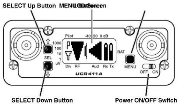
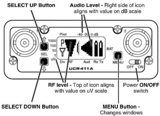
LCD Screen
The LCD Screen is a graphics-type Liquid Crystal Display that is used to monitor system operation and configure the UCR411A.
MENU Button
The MENU button steps through the four primary windows and setup screens.
SELECT Up/Down Buttons
The SELECT Up/Down buttons are used to select various options within each display selection and to set the operating frequency of the receiver.
Power ON/OFF Switch
The Power ON/OFF switch is used to apply battery or external power to the unit.
Rear Panel Features
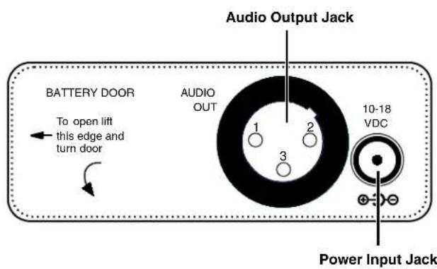
XLR Audio Output Jack
This is a standard XLR configuration with pin 2 "positive" with reference to hand-held and plug-on transmitters. With lavaliere microphones and belt-pack transmitters, however, phase will vary with different types of microphones (2-wire vs. 3-wire for example). The audio output is balanced but not floating, so an unbalanced signal is available using pin 1 as ground and pin 2 as signal, leaving pin 3 open.
Power Input Jack
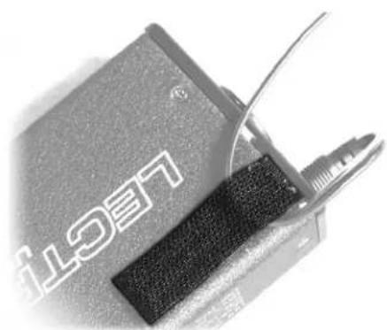
The power input jack can accept 10-18 VDC - the center pin is positive and sleeve is ground. The input is diode protected to prevent damage if the power is applied with reversed polarity, but the unit will not work until the reversed polarity condition is fixed. The small Velcro strip can be used as a strain relief and retainer on the power cable to avoid accidental disconnection. Attach the adhesive strip side to the side of the receiver or mount with the opening end of the strip up - place the cable in the strip and secure.
natural_image
Close-up of a battery pack and its connector with a cable, no visible text or symbolsMain Window (LCD)
The Main Window displays information concerning the condition of the Pilot Tone, antenna phase, RF and audio signal levels and battery conditions for both the receiver and the associated transmitter. It is also the access portal to menu selections for setting up the receiver and searching for clear frequency channels. (See Menu Selections from Main window and Frequency Scan Mode.)
| Icon | Description |
| P | Pilot Tone IndicatorA steady “P” icon will be displayed when a pilot tone from the transmitter is present, in those compatibility modes which use pilot tone: 200 Series, Digital Hybrid (400 Series), IFB and Mode 6. The icon will blink if no pilot tone is present from the transmitter, and it will change to a small “b” if the pilot tone has been bypassed. To bypass the pilot tone, hold MENU and press the UP button. Hold MENU and press UP again to restore normal pilot tone squelch. Bypassing the pilot tone also disables the squelch, so the receiver will produce loud noise when no matching transmitter signal is being received, regardless of which compatibility mode is selected. |
| b | |
| T | Antenna Phase IndicatorThis icon shows antenna phase switching activity. As the antenna phase is switched, the symbol will flip vertically. |
| T | RF LevelThis icon changes in size vertically to indicate the strength of the incoming RF signal. RF levels are engraved from 1uV to 1000uV on the bezel to the left of the LCD display. |
| T | Audio LevelThis icon changes in size horizontally to indicate the audio level (modulation) of the signal received from the transmitter. The icon display will change to a solid rectangular block when the audio signal is being limited in the transmitter. Levels in dB are engraved into the bezel above the LCD display. |
| T | Battery LevelsThe icon above the Rx symbol indicates the receiver battery condition and will flash when approximately one hour of operating time is remaining. When external power is being used, the Rx battery icon changes to look like a power plug. The area above the Tx symbol features either a transmitter battery status icon or the transmitter battery timer, depending on the TXBAT setting. The transmitter battery status icon is available only in compatibility modes supporting battery telemetry (400 and 200 Series). In such cases, the transmitter battery status icon appears 5 to 10 seconds after the transmitter signal is acquired. If selected in the TXBAT setup screen, the transmitter battery timer is available in any compatibility mode. It accumulates hours and minutes that the communications link is active, retaining the timing even when the receiver is off. |
Menu Selections from Main Window
flowchart
graph TD
    A["SETUP LEVEL"] -->|Press UP| B["LEVEL 00 dBu"]
    B -->|Press MENU| C["TYPE? 00 dBu"]
    C -->|Press UP| D["ILVL 1K 00 dBu"]
    D -->|Press MENU| E["TX 7.2V RX 8.2V"]
    E -->|Press MENU| F["TV40 AE 631.800"]
    F --> G["Battery Level window"]
    G --> H["SETUP EXIT"]
    H -->|Press MENU| I["TX 7.2V RX 8.2V"]
    I --> J["Frequency window"]
    J --> K["SETUP COMPAT"]
    K -->|Press UP| L["COMPAT NA400"]
    L -->|Press MENU| M["SETUP TUNING"]
    M -->|Press UP| N["SETUP SmtNR"]
    N -->|Press MENU| O["Phase INVERT"]
    O -->|Press MENU| P["Output Phase"]
    P --> Q["TX BAT 9V ALK"]
    Q -->|Press MENU| R["SETUP TX BAT"]
    R -->|Press UP| S["SETUP TONE"]
    S -->|Press MENU| T["SETUP LEVEL"]
    T -->|Press UP| U["SETUP TONE"]
    U --> V["SETUP TX BAT"]
    V --> W["SETUP SmtNR"]
    W --> X["SETUP TUNING"]
    X --> Y["SETUP COMPAT"]

    style A fill:#f9f,stroke:#333
    style B fill:#f9f,stroke:#333
    style C fill:#f9f,stroke:#333
    style D fill:#f9f,stroke:#333
    style E fill:#f9f,stroke:#333
    style F fill:#f9f,stroke:#333
    style G fill:#f9f,stroke:#333
    style H fill:#f9f,stroke:#333
    style I fill:#f9f,stroke:#333
    style J fill:#f9f,stroke:#333
    style K fill:#f9f,stroke:#333
    style L fill:#f9f,stroke:#333
    style M fill:#f9f,stroke:#333
    style N fill:#f9f,stroke:#333
    style O fill:#f9f,stroke:#333
    style P fill:#f9f,stroke:#333
    style Q fill:#f9f,stroke:#333
    style R fill:#f9f,stroke:#333
    style S fill:#f9f,stroke:#333
    style T fill:#f9f,stroke:#333
    style U fill:#f9f,stroke:#333
    style V fill:#f9f,stroke:#333
    style W fill:#f9f,stroke:#333
    style X fill:#f9f,stroke:#333
    style Y fill:#f9f,stroke:#333
    style Z fill:#f9f,stroke:#333
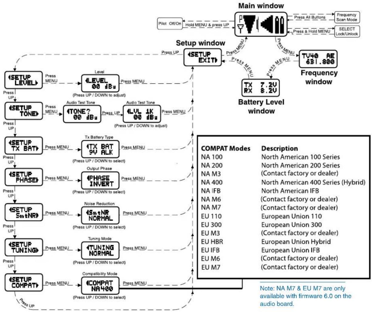
From the Main window, you can navigate to the Frequency, Battery Level and Setup windows in a circular sequence by pressing the MENU button.
Frequency Window
TVxx - Indicates the television broadcast channel (xx) this frequency falls within.
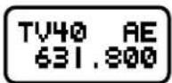
Transmitter switch settings (AE in the illustration) -These are the correct switch settings for the frequency switches on your transmitter - see your transmitter instructions.
Frequency - Press the SEL Up and Down buttons to change the frequency of the receiver.
Note: Be certain to change the transmitter frequency switches to match the settings shown in the upper left hand corner of the Frequency window.
When the TUNING mode is set to NORMAL, the SEL Up and Down buttons tune in single channel increments. In the group tuning modes, the SEL Up and Down buttons move among the selected intermod-free frequencies.
Tuning shortcuts: In NORMAL tuning mode, MENU+UP and MENU+DOWN tune in 16 channel increments for faster tuning. In the group tuning modes, MENU+UP jumps to the first frequency in the group and MENU+DOWN jumps to the last one in the group.
Battery Level Window
This window shows the transmitter (TX) and receiver (RX) battery voltage. These levels will flash when there will be about one hour operating time remaining. The RX voltage changes to EX when operating on external power and displays the external power source voltage. (Disclaimer: We cannot guarantee 0.1 Volt accuracy.)
SETUP Window
In the SETUP window, the SEL Up and Down buttons scroll through a list of eight possible setup screens:
EXIT, LEVEL, TONE, TXBAT, PHASE, SmtNR (in 400 Series mode only), TUNING and COMPAT. Each of these setup screens allows the user to change the associated operating parameters. Pressing the MENU button accesses whatever mode is identified in the Setup window. Pressing the MENU button whenever EXIT is displayed returns the user to the Main window.
SETUP EXIT
LEVEL Setup Screen
The LEVEL setup screen displays the audio output level of the receiver in dBu. Use the SEL Up or Down buttons to change the level. Range is
from -50 to +5 dBu in 1 dB steps. Press the MENU button to leave this screen.
LEVEL 00 dBu
TONE Setup Screen
The TONE setup screen enables an audio test tone at the receiver output for precise level matching with other equipment. The first screen prompts you to press the SEL Up button to enable the tone at the receiver output jack. The next screen that appears allows the level to be adjusted in 1dB steps using the SEL Up and Down bu
TONE 00 dBu
When the audio test tone is enabled, the received audio is muted and an internally generated 1 kHz test tone is routed to the XLR connector. Since there is only one audio output level setting for both the received audio and test tone, the level set here will be retained in the receive mode (it will supersede the setting made in the LEVEL setup screen.) The test tone has 1% distortion and is intended for confirmation of output levels only. To exit the test tone screen and stop the tone press the MENU button.
LVL 1K +04 dBu
TXBAT Setup Screen
The TXBAT setup screen allows you to select the exact battery being used in the transmitter to provide more
accurate battery level monitoring. Four different types of batteries are commonly used in Lectrosonics transmitters: 9 Volt alkaline, 9 Volt lithium, AA alkaline, and AA lithium. Correctly set, this will ensure that adequate warning will be provided in advance of battery failure. Use the SEL Up and Down buttons to select the transmitter battery. Press MENU to leave this screen.
4TX BAT 9V ALK
In native 400 Series mode as well as in the 200 Series compatibility mode, the TXBAT menu offers six choices:
9V ALK Transmitter uses a 9V alkaline battery. Monitor voltage with battery icon in main window.
9V LTH Transmitter uses a 9V lithium battery. Monitor voltage with battery icon in main window.
9V TIM Transmitter uses a 9V battery. Display its voltage normally in the battery level window but monitor its status with the battery timer in the main window.
AA ALK Transmitter uses a AA alkaline battery. Monitor voltage with battery icon in main window.
AA LTH Transmitter uses a AA lithium battery. Monitor voltage with battery icon in main window.
AA TIM Transmitter uses an AA battery. Display its voltage normally in the battery level window but monitor its status with the battery timer in the main window.
The 9V TIM and AA TIM settings are most useful for NiMH batteries as they do not exhibit reliably identifiable voltage drops as they discharge.
In compatibility modes other than 400 Series and 200 Series, no battery telemetry information is available so the TXBAT setup screen offers only two choices:
NOTIMER Display no transmitter battery status in the main window.
TIMER Monitor the transmitter battery status with the battery timer in the main window.
Note: To reset the battery timer, hold MENU and SEL Down together for one second.
PHASE Setup Screen
The PHASE setup screen allows the audio output phase to be inverted.
The SEL Up and Down buttons can be used to toggle between normal and inverted phase. Press MENU to leave this screen.
4PHASE INVERT
SmartNR Setup Screen
The SmartNR setup screen (available in 400 Series compatibility mode only) places the Smart Noise Reduction algorithm in one of three modes. In the OFF position, no noise reduction is applied, for complete transparency. In the NORMAL position (factory default setting), a moderate amount of noise reduction is applied, dramatically reducing hiss with virtually no discernible side effects. In the FULL
Sm t NR OFF
4Sm t NR NORMAL
Sm t NR FULL
position, the transparency is superior to the Lectrosonics noise reduction system used for many years in the 195 and 200 series systems. Try switching between the three modes to decide what setting is correct for your application. Refer to the Smart Noise Reduction section in the General Technical Description chapter for more detailed information about this feature.
TUNING Setup Screen
The TUNING setup screen allows selection of one of four factory set frequency groups (Groups A through
D), two user programmable frequency groups (Groups U and V) or the choice to not use groups at all.
TUNING NORMAL
Note: User Group Tuning available in units with firmware version 3.0 and above.
In the four factory set frequency groups, eight frequencies per group are preselected. These frequencies are chosen to be free of intermodulation products. (See Frequency Coordination.)
In the two user programmable frequency groups, up to 16 frequencies can be programmed per group.
Note: The Tuning setup screen only selects the tuning mode (NORMAL or Group Tuning) and not the operating frequency. Actual operating frequencies are chosen through the Frequency Window.
Frequency Window Behavior
If NORMAL tuning mode is selected, the SEL Up and Down buttons select the operating frequency in single channel (100 kHz) increments and the MENU+Up and MENU+Down shortcuts tune in 16 channel (1.6 MHz) increments.
There are two types of group tuning modes: factory preset groups (Grp A through D) and user programmable frequency groups (Grp U and V).
When using Group Tuning, a lower case “a, b, c, d, u” or “v” will be displayed to the immediate left of the transmitter switch settings in the Frequency Window, indicating which group is selected. If currently tuned frequency is not in the current tuning group, the indicator will blink.
If a factory tuning group has been selected, pressing either the SEL Up or Down button will select the nearest factory selected frequency in that group above or below the current frequency.
User Programmable Frequency Group Behavior
The user programmable frequency groups work very similarly to the factory groups with a few exceptions. The most obvious difference is the ability to add or remove frequencies from the group. Less obvious is the behavior of a user programmable frequency group with only one, or no, entries.
A user programmable frequency group with only one entry will only display that one frequency regardless of how many times the SEL Up or Down buttons are pressed (providing the MENU button is not pressed at the same time).
A user programmable frequency group with no entries reverts to non-group-mode behavior, i.e., access is allowed to all 256 available frequencies in the selected receiver module's frequency block. However, once a frequency has been added to the tuning group, this behavior changes to group-mode behavior where the
MENU button must be pressed and held while either the SEL Up or Down buttons are pressed to access frequencies that are not part of the current tuning group.
Adding/Deleting User Programmable Frequency Group Entries
Note: Each user programmable frequency group (“u” or “v”) has separate contents. It is suggested to review the section titled Frequency Coordination prior to adding frequencies in order to minimize potential intermodulation problems.
- Start from the Frequency Window and verify that a lower case "u" or "v" is present next to the transmitter switch settings.
- While pressing and holding the MENU button press either the SEL Up or Down button to move to one of the 256 available frequencies in the block. Whenever the selection comes to rest on a frequency that is in the current group, the group tuning mode indicator (letter "u" or "v") will give a steady indication. On frequencies that are not in the group, the indicator will blink.
- To add or remove the displayed frequency from the group, hold down the MENU button while pressing and holding the SEL Up button for about a second. The group tuning mode indicator will stop blinking to show that the frequency has been added to the group, or begin blinking to indicate that the frequency has been removed from the group.
COMPAT Setup Screen
The COMPAT setup screen selects the type of transmitter used with the UCR411A. The available modes are:
COMPAT NA 400
NA 400 North American - Native 400 Series Digital Hybrid mode
NA 100 Lectrosonics 100 Series compatibility
NA 200 Lectrosonics 200 Series compatibility
NA M3 Compatible with certain non-Lectrosonics transmitters*
NA IFB Compatible with all Lectrosonics IFB transmitters.
NA M6 Compatible with certain non-Lectrosonics transmitters*
NA M7 Compatible with certain non-Lectrosonics transmitters*
EU HBR European Union - Native 400 Series Digital Hybrid mode
EU 100 European Union - 100 Series compatibility
EU 200 European Union - 200 Series compatibility
EU M3 European Union - Compatible with certain non-Lectrosonics transmitters*
EU IFB European Union - Compatible with all Lectrosonics IFB transmitters.
EU M6 European Union - Compatible with certain non-Lectrosonics transmitters*
EU M7 European Union - Compatible with certain non-Lectrosonics transmitters*
*Contact Lectrosonics for a list of compatible transmitters.
Frequency Scan Mode
flowchart
graph TD
    A["Press All 3 Buttons"] --> B["Scan"]
    B --> C["To Exit Scan Mode, Press All 3 Buttons From Any Window."]
    C --> D["USE OLD USE NEW"]
    D --> E["Freq Window"]
    F["Fine View"] --> G["View"]
    G --> H["Press Menu"]
    H --> B
    I["Press Any Button"] --> B
    J["Press Menu"] --> G
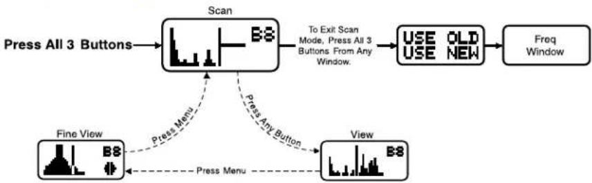
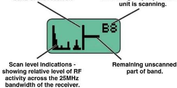
To start the scanning, press both SEL Up/Down buttons and the MENU button at the same time. The display will switch to the SCAN WINDOW and start scanning immediately. Data gathered during a scan is stored until it is purposely erased or the power is turned off. Previous data will remain and subsequent scans can be made to search for additional signals or to accumulate higher peaks.
To stop scanning, press the MENU button once. The scanning will stop immediately, and the display will switch to the VIEW window. In this window, each vertical band of the display represents 8 frequencies (800 kHz). Pressing the SEL Up or Down buttons will scroll the cursor coarsely across the tuning range. The transmitter switch settings matching the frequency indicated by the cursor are shown in the upper right corner of the screen.
Spectrum data is collected only when the receiver is scanning. Successive scanning with repeated passes through the tuning range will accumulate the highest peaks encountered to aid in finding clear frequencies. To clear the scan memory without leaving scan mode, turn the power switch off and back on quickly.
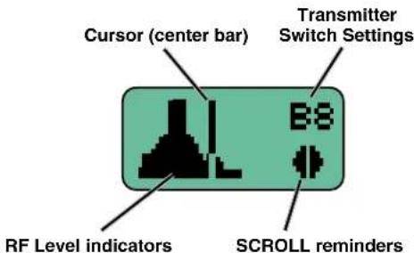
Pressing the MENU button once will shift the display to the FINE VIEW window which will show an expanded portion of the spectrum around the cursor.
In the FINE VIEW window, each vertical band represents one frequency the UCR411A is capable of tuning. The upper right corner shows the transmitter switch settings for the frequency indicated by the cursor. In this screen, a vertical center bar is the cursor. Underneath the switch settings are two arrows to remind you that this is a partial picture of the spectrum and that you can scroll left or right to view the entire spectrum of the receiver by pressing the SEL Up and Down buttons.
Pressing the SEL Up button will make the display scroll left, showing higher frequencies. Pressing the SEL Down button will make the display scroll right, showing lower frequencies. The cursor remains in place while the display scrolls left or right
In addition to assessing the congestion within the RF tuning range of the receiver, the scanning mode is also used to find a clear operating frequency. Scroll through the screen and find a frequency where no RF signals are present (or in the worst case, only very weak RF signals). With the cursor on this frequency, simultaneously press the SEL Up, Down and MENU buttons to leave the scan mode.
Scan & VIEW WINDOW Elements
Cursor - shows relative position of the scanner within the 25Mhz band of the receiver.
Switch Settings - shows the transmitter switch settings - will change rapidly while the unit is scanning.
Fine VIEW WINDOW Elements
When leaving the scan mode, you are given the option of using the frequency the unit was on before entering the scan mode, or using the frequency just selected in the scan mode. The display shows USE OLD and USE NEW to prompt you to make a frequency selection. To accept the new frequency just selected in the scan mode, press the SEL Down button for USE NEW. To return to the frequency you were using before entering the scan mode, press the SEL Up button for USE OLD. (The MENU button defaults to USE OLD).
Once you leave the scan mode, the Frequency Window will be displayed. Set your transmitter switches to the same settings as shown on the display and your system will be ready for operation.
Antenna Use and Placement
The receiver is supplied with two straight BNC whip antennas. In some circumstances remote antennas may be useful for improving reception. Position remote antennas at least three or four feet apart and at least three or four feet from large metal surfaces. If this is not possible, try to position the antennas so that they are as far away from the metal surface as is practical. It is also good to position the receiver so that there is a direct "line of sight" between the transmitter and the receiver antenna. In situations where the operating range is less than about 100 feet, the antenna positioning is much less critical.
Note: Be careful about the length of cabling from antenna to receiver. Long cable runs can have serious signal loss. Lectrosonics has in-line RF amplifiers suitable for compensating for long cable runs. Contact your dealer or the factory for more information.
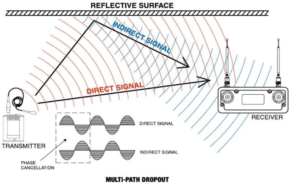
A wireless transmitter sends a radio signal out in all directions. This signal will often bounce off nearby walls, ceilings, etc. and a strong reflection can arrive at the receiver antenna along with the direct signal. If the direct and reflected signals are out of phase with each other a cancellation may occur. The result would be a "drop-out." A dropout sounds like either audible noise (hiss), or in severe cases, may result in a complete loss of the carrier and the sound when the transmitter is positioned in certain locations.
A UHF dropout sounds like a very brief "sshhht" or a "swishing" sound. Moving the transmitter even a few inches will change the sound of the dropout, or eliminate it. A dropout situation may be either better or worse as a crowd fills or leaves the room, or when the transmitter or receiver is operated in a different location.
The receiver offers a sophisticated diversity design which overcomes dropout problems in almost any situation. In the event, however, that you do encounter a dropout problem, first try moving one of the remote antennas at least 3 or 4 feet from its original location (or move the receiver if the antennas are attached directly to it). This may alleviate the dropout problem at that location. If dropouts are still a problem, try moving the antennas to an entirely different location in the room or moving them closer to the transmitter location.
Lectrosonics transmitters radiate power very efficiently, and the receivers are very sensitive. This reduces dropouts to an insignificant level. If, however, you do encounter dropouts frequently, call the factory or consult your dealer. There is probably a simple solution.
Installation and Operating Instructions
- Install a fresh battery or connect an external power source to the UCR411A and attach the antennas.
- Unless frequency settings have been previously assigned, scan for an open frequency and set both the receiver and transmitter to that frequency. (See Finding Clear Frequencies.)
- Connect the audio cable to the Receiver Audio Out XLR jack.
- Set the Power ON/OFF switch to ON and verify that the LCD panel activates.
- Adjust the transmitter gain. THIS IS PERHAPS THE MOST IMPORTANT STEP IN THE SET UP PROCEDURE. Refer to your transmitter manual's Operating Instructions section for details on how to adjust the transmitter gain. In general, adjust the transmitter gain so that the voice peaks will cause the audio modulation indicators on the receiver and transmitter to show full modulation on the loudest peak audio levels. Normal levels should cause the UCR411A's audio level icon to fluctuate fully. This will result in the best possible signal to noise ratio for the system.
Important:
- Adjust the transmitter gain before you adjust the receiver output level.
- When the transmitter if fully modulated, its limiter will prevent any further increases in level.
- The receiver output circuitry is set to run at full output, and the level control is simply an attenuator. There is no difference in signal to noise ratio across the entire adjustment range of the receiver output level. The transmitter input gain is the critical adjustment that will affect the signal to noise ratio.
- Adjust the Audio Output according to the type of input on your equipment. Use the LEVEL menu and adjust the level with the SELECT Up and Down buttons.
The input levels of different cameras, VCRs, and PA equipment vary, which may require that you adjust the AUDIO OUT to an intermediate position. Try different settings and listen to the results. If the output of the receiver is too high, you may hear distortion or a loss of the natural dynamics of the audio signal. If the output is too low, you may hear steady noise (hiss) along with the audio. The UCR411A audio output is designed to drive any audio input device from microphone level to +10dBu line level.
Note: The test tone output is especially useful for an exact level match. With the test tone running, adjust for the maximum desired peak level using the metering on the connected device.
Finding Clear Frequencies
The following procedure will help you identify RF signals in the area and find clear channels for operating the wireless system.
- Ensure transmitter is turned off. Turn on the receiver and wait a few seconds until the Main Window appears on the LCD
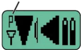
- Ensure the receiver is NOT in PILOT TONE BY-PASS mode. (A "P" will be blinking in the upper left corner of the Main Window.)
Pilot Tone Indicator
natural_image
Pure electrical circuit lines without any symbolsTO ENABLE PILOT BYPASS: Step the MENU key to the MAIN window. Press the MENU and UP keys together for b bypassed pilot or p normal pilot.
- Simultaneously press the MENU and SELECT Up and Down buttons to enter Scan Mode.
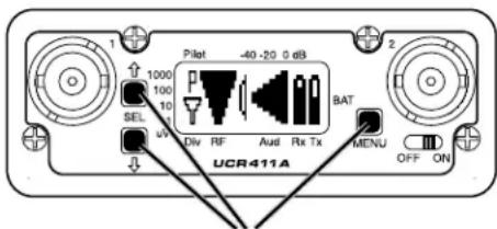
Press all three buttons at the same time and the receiver will start scanning.
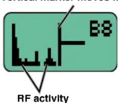
- View the LCD while the receiver is scanning. The vertical marker will move across the display from left to right. RF activity will be indicated by dark areas in the display.
Vertical marker moves left to right
- RF signal strength is indicated by markings in microvolts on the front panel to the left of the LCD.
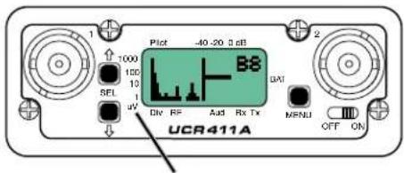
RF level in microvolts
Look for clear channels in the spectrum where there is no RF activity. Scanning will repeat and continue until a button is pressed.
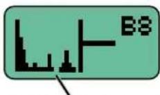
No RF activity (clear channel)
- If necessary, press the MENU button to zoom in for greater detail for fine adjustment.
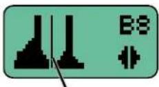
Zoom in to make fine adjustments
- Then press the SEL Up and Down arrows to move the marker to the middle of a clear area where there is no RF activity. If an area with no RF activity cannot be found anywhere in the spectrum, locate one with the least amount of RF activity.
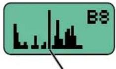
Move marker to area with no RF activity
- Press all three buttons (SEL Up and Down and MENU) to move to the next screen. Two options will be shown.
Press the SEL Down arrow button to select the USE NEW option and set the receiver to the new frequency just found in scanning.
Press the SEL Up arrow button to select USE OLD and return to the frequency that was set before scanning.

Use the SEL Up and Down arrow buttons to select the old or new frequency.
Locking and Unlocking the UCR411A Front Panel Controls
The front panel controls can be "LOCKED" to prevent accidental changes being made during operation and handling.
To LOCK the UCR411A
Press and hold the MENU button until a bar tracks horizontally across the LCD screen and the word "LOCKED" appears. If the MENU button is released before the word "LOCKED" appears, the unit will remain UNLOCKED. When in a LOCKED state, the pilot tone bypass toggle is also defeated.
In LOCKED state, the use of the MENU and SEL Up/Down buttons are limited to "view only" and any attempts to change selections will result in an LCD screen displaying the word "LOCKED." The unit cannot be used for RF scanning when it is set in the LOCKED state.
To UNLOCK the UCR411A
Press and hold the MENU button until a bar tracks horizontally across the screen and the word "UNLOCKED" is displayed on the LCD screen. When the unit is UN-LOCKED, all settings can be altered.
The UCR411A can only be LOCKED or UNLOCKED from one of the main windows. (There are four of them.) Also, it cannot be switched between LOCKED and UNLOCKED modes when it is in a scanning mode or from other subordinate screens.
Replacing the Batteries
Lift and rotate the battery door to open it.
Observe the battery contacts inside the compartment. The larger contact is the neg. (-) terminal and the smaller contact is the pos. (+) terminal.
Insert the contact end of the battery first, making sure the large terminals are aligned with the large contacts in the compartment.
Depress the batteries slightly to allow the door to rotate and close. The battery contacts are spring loaded to maintain constant pressure. The door with snap into place place when it is fully closed.
CAUTION: Lithium batteries will expand and swell if allowed to go into a deep discharge. Be sure to remove lithium batteries as soon as possible after they are depleted. If lithium batteries are allowed to fully discharge while still inside the battery compartment, they will be very difficult to remove.
Stuck lithium batteries can be avoided by removing the label wrapping around the battery before use. This will allow the battery to swell but will still leave enough room in the compartment for the battery to fall out normally.
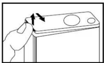
natural_image
Hand pressing a button on a battery (no text or symbols visible)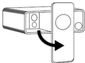
natural_image
Diagram of a device with a scroll wheel and directional arrow indicating rotation (no text or symbols)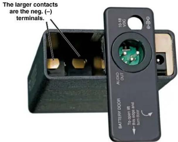
Antenna/Block Reference Table
The A8U whip UHF whip antenna supplied with the receiver is factory cut to a specific frequency block as shown in the table below. A colored cap and label are used on blocks 21 through 29, and a black cap and label are used on the other blocks to denote the frequency range of each model.
The chart is useful for fabricating an antenna from coaxial cable or other materials, or for identifying the frequency of an antenna that is not marked. The lengths shown are specifically for the A8U whip antenna with a BNC connector, as determined by measurements with a network analyzer. The optimal length of the element in other designs will likely be different than those shown in this table, but since the bandwidth is typically wider than the specified block, the exact length is not critical for useful performance in whip, dipole and coaxial designs.
BLOCK FREQUENCY CAP ANTENNA RANGE COLOR WHIP LENGTH
Note: Not all Lectrosonics products are built on all of the blocks covered in this chart.
| 470 470.100 - 495.600 Black w/ Label 5.47" | |
| 19 486.400 - 511.900 Black w/ Label 5.19" | |
| 20 512.000 - 537.500 Black w/ Label 4.95" | |
| 21 537.600 - 563.100 Brown 4.73" | |
| 22 563.200 - 588.700 Red 4.47" | |
| 23 588.800 - 614.300 Orange 4.23" | |
| 606 606.000 - 631.500 (Use Block 24) 4.00" | |
| 24 614.400 - 639.900 Yellow 4.00" | |
| 25 640.000 - 665.500 Green 3.80" | |
| 26 665.600 - 691.100 Blue 3.61" | |
| 27 691.200 - 716.700 Violet (Pink) 3.46" | |
| 28 716.800 - 742.300 Grey 3.31" | |
| 29 742.400 - 767.900 White 3.18" | |
| 30 768.000 - 793.500 Black w/ Label 3.08" | |
| 31 793.600 - 819.100 Black w/ Label 2.99" | |
| 32 819.200 - 844.700 Black w/ Label 2.92" | |
| 33 844.800 - 861.900 Black w/ Label 2.87" |

Note: This line should be 6.00" long.
Pre-coordinated Frequencies
Interference from IM (intermodulation) is a potential problem in all multi-channel wireless systems, so proper frequency coordination is always required to avoid noise, range and dropout problems. Your options to accomplish this include:
• Using the pre-coordinated frequency groups
• Performing a system checkout (See Multi-channel System Checkout)
- Calling Lectrosonics for assistance
Groupings of compatible frequencies have been created to minimize intermodulation problems in multiple channel wireless systems. The frequencies can be used with Digital Hybrid and analog Lectrosonics wireless equipment. Compatibility with other brands is likely, but not guaranteed by Lectrosonics.
NOTE: Pre-coordinated frequencies do not guard against interference from outside sources.
When a pre-coordinated group is selected, it is still necessary to check for interference from outside sources. Groups a, b, c and d each store 8 frequencies. After selecting one of these groups, step through each frequency one at a time and check for interference before trying to use the frequency.
To check for interference, set the frequency on the receiver, then return to the Main Window and observe the RF level indicator with the matching transmitter turned OFF.
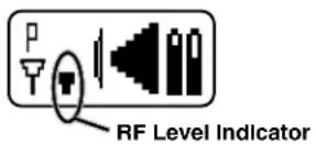
Even a weak signal, as shown here, will have a significant effect on operating range and dropouts. When interference is present with the transmitter turned off, a warning message will flash on the screen periodically.
Pre-coordinated frequencies within each block are arranged in four groups (Grp) as shown at right.
Example: Block 22
The uppermost eight frequencies comprise Grp a, the eight just below them comprise Grp b, and so on.
Grp a and Grp b are compatible with one another.
Grp c and Grp d are compatible with one another.
There is no assurance that the upper 16 (a,b) are compatible with the lower 16 (c,d).
| FREQ SW SET US TV CH | ||
| 563.700 | 5 | N29 |
| 564.300 | B | N29 |
| 565.200 | 4 | N29 |
| 565.800 | A | N29 |
| 567.100 | 7 | N30 |
| 566.000 | 0 | N30 |
| 566.500 | 5 | N30 |
| 569.300 | D | IV30 |
| 575.700 | D | IV31 |
| 577.900 | 3 | N31 |
| 578.600 | A | N32 |
| 579.900 | 7 | IV32 |
| 581.700 | 9 | IV32 |
| 582.600 | 2 | N32 |
| 585.200 | C | N33 |
| 587.500 | 3 | IV33 |
| FREQ SW SET | U | S TV CH |
| 570.100 4 | 5 | w30 |
| 570.700 4 | B | w30 |
| 571.600 5 | 4 | w30 |
| 572.200 5 | A | w31 |
| 573.200 6 | 4 | w31 |
| 574.400 7 | 0 | w31 |
| 574.900 7 | 5 | w31 |
| 575.500 7 | B | w31 |
| 581.100 5 | 3 | w32 |
| 582.100 8 | D | w32 |
| 582.600 0 | 2 | w32 |
| 584.300 0 | 3 | w32 |
| 585.000 0 | A | w32 |
| 585.600 6 | 0 | w32 |
| 586.300 6 | 7 | w32 |
| 588.100 9 | 9 w32 |
Diagnostics
Multi-channel System Checkout
Interference can result from a wide variety of sources including TV station signals, other wireless equipment in use nearby, or from intermodulation within a multi-channel wireless system itself. Regardless of how the frequencies were coordinated, a final checkout procedure is always a good idea.
Scanning with the RF spectrum analyzer built into the Venue system will identify external RF signals, but it does not address the compatibility of the selected frequencies.
The pre-coordinated frequencies on the chart on the previous pages address in-system intermodulation, but obviously cannot take into account RF signals from external sources that may be present in the location where the system will be operating.
In some cases, you can run the scanner to find clear TV channels, then find enough pre-coordinated frequencies in the tuning groups (Grp a through Grp d) to operate on the clear TV channels. Even so, it is still a good idea to go through the check out procedure because you can encounter interference from other wireless, IFB and intercom systems when you get to the production or installation site.
1. Set up the system for testing.
Place antennas in the position in which they will be used and connect to the receivers. Place transmitters about 3 to 5 feet apart, about 25 to 30 feet from the receiver antennas. If possible, have all other equipment on the set, stage or location turned on as well, especially any mixing or recording equipment that will be used with the wireless system.
2. Set all receivers on clear channels.
Turn on all receivers, but leave the transmitters off. Observe at the RF signal strength indicator for each receiver module. If a signal is present, change the frequency to a clear channel where no signal is indicated. If a completely clear channel cannot be found, select the frequency with the lowest RF level indication. Once all receiver modules are on clear channels, go to step 3.
3. Turn each transmitter on one at a time.
Start with all transmitters turned off. As you turn on each one, look at the matching receiver to verify a strong RF signal is received. Then, look at the other receivers and see if one of them is also picking up the signal. Only the matching receiver should indicate a signal. Change frequencies on either system slightly until all channels pass this test, then check again to see that all channels are still clear as done in step 2.
4. Turn each transmitter off one at a time.
With all transmitters and receivers turned on, turn each transmitter off one at a time, in turn, and look at the RF level indicator on the matching receiver module. The RF level should disappear or drop to a very low level. If it does not, change frequency on that receiver and transmitter and try it again. When a clear frequency is found, turn the transmitter on and move on to the next channel.
IMPORTANT: Any time a frequency is changed on any of the systems in use, you must start at the beginning and go through this procedure again for all systems. With a little practice, you will be able to do this quickly and save yourself some “multi-channel grief.”
Pilot Tone Bypass
Some wireless equipment uses a supersonic "pilot tone" to control the squelch (audio mute) of a receiver module to keep it silent until a valid signal is received. When a signal with the correct pilot tone is received, the squelch opens and audio is delivered to the output. Pilot tone squelch control also eliminates transients (clicks and pops) when transmitters are turned on and off. Pilot tone is supported in the Digital Hybrid compatibility modes for those systems that use it.
Pilot tone control can be bypassed as a diagnostic tool. Bypass opens the audio output of the receiver unconditionally, allowing you to listen to any signals entering the receiver to help identify their source. Pilot tone bypass will also allow you to use a transmitter that has a defective pilot tone circuit.
CAUTION: When pilot tone is bypassed and the transmitter is turned off, excessive noise will be present. Turn the audio level down before bypassing pilot tone.
Replacement Parts and Accessories
32251
Velcro mounting strips
CCMINI
Zippered, padded vinyl system pouch
CH12
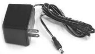
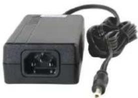
AC power supply with US type 2-pin plug on housing, 110 VAC input; 12 VDC, 400 mA output.
VSR1
Thin velcro loop for power cable strain relief.
A8U
UHF marine phosphor bronze antenna - straight connector, specify block.
PS70
A/C power supply with 3-pin NEMA socket on housing, 100-240 VAC input; 13.8 VDC, 2.8 A (max.) output.
UMCWB
Rack-mount multicoupler combining antenna and power distribution for up to four Lectrosonics wireless microphone receivers.
SNA600
Collapsible dipole antenna adjustable from 550 MHz to 800 MHz. Ideal for situations where a full 360 degree receiving pattern is required as opposed to a directional pattern.
ALP Series (ALP500, ALP620, ALP650)
"Shark fin" Log Periodic Dipole Array (LPDA) antennas provide useful directional pattern over 500 to 800 MHz range. Ideal for portable applications including temporary setups for field production
ARG15-ARG100
Coaxial cables for remote antennas are available from Lectrosonics in a variety of lengths - from 2 to 100 ft. Cables include Velcro tie wraps.
21425
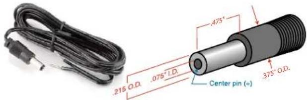
6 ft. long power cord; coaxial to stripped & tinned leads. Coaxial plug: ID-.080"; OD-.218"; Depth-.5". Fits all compact receiver models that use CH12 power supply.
21472
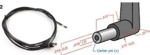
6 ft. long power cord; coaxial to stripped & tinned leads. Right angle coaxial plug: ID-.075"; OD-.218"; Depth-.375". Fits all compact receiver models that use CH12 power supply.
VSR1

natural_image
Close-up of a battery pack with a black strap and cable, no visible text or symbolsCH12
natural_image
Black rectangular electronic device with two leads and a coiled cable (no visible text or symbols)PS70
natural_image
Black rectangular electronic device with power connector and cable, no visible text or symbolsA500RA

natural_image
Close-up of a metallic BDN2018 sensor with black and blue connectors (no visible text or symbols)21425
21472
Troubleshooting
Symptom
Possible
Cause
INITIAL POWER ON
LCD display not active or lit. External power supply disconnected or inadequate.
Main power supply fuse tripped. Turn the receiver off, remove the cause of the overload and turn the receiver back on.
Wrong polarity power source. The external DC in requires POSITIVE to be on the center pin.
Battery may be low. Try a fresh battery.
Version message shows DSP or COM. assistance.
This indicates an internal error. Please contact the factory for
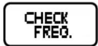
Display indicates CHECK FREQ.
This is a warning that a strong signal is present but it's far enough
away from the center of the channel that the audio is likely to be distorted. Try relocating to unused frequencies.
If this doesn't remove the warning message, the transmitter or receiver may need repair.
PILOT TONE SQUELCH
Pilot Tone indicator (P) present, but no sound
Audio output cable bad or disconnected.
Audio Output level too low. Use the built-in test tone to verify levels.
Pilot Tone Indicator (P) keeps flashing when transmitter turned on
Pilot tone detection can take several seconds. Turn on the transmitter power (and the audio switch on some models) and wait 3 to 5 seconds for the "P" to indicate steadily.
Transmitter and receiver not on same frequency.
Receiver compatibility mode does not match the transmitter in use. (See Menu Selections from Main Window, COMPAT Window.)
Noise on audio and Pilot Tone Indicator is "b".
The pilot tone bypass has been activated. Hold MENU and press UP to reset (works only from the Main Window).
Pilot Tone Indicator not present but receiving audio
Receiver is set to a compatibility mode that doesn't use Pilot Tone. Check that receiver compatibility mode matches the transmitter in use as any sufficiently strong signal can unsquelch the receiver in this mode, compatible or not.
NOTE: In the 400 Series and 200 Series compatibility modes, the PILOT indicator on the front panel shows as a solid "P" to indicate that the audio has been turned on at the transmitter, and that the audio output on the receiver is enabled. When the "P" is on, the audio is enabled. If the "P" is flashing the pilot tone is not detected and the audio will be muted (squelched).
In the other compatibility modes, no pilot tone is used and the "P" is never displayed. Audio is present whenever the receiver detects a sufficiently strong signal.
Regardless of the compatibility mode, activating the "pilot bypass" function causes a lowercase "b" to appear in the pilot indicator position on the main window and forcibly unsquelches the audio.
Symptom
Possible
Cause
ANTENNAS AND RF SIGNAL STRENGTH
RF Level is weak. Receiver may need to be moved or reoriented.
Antenna on transmitter may be defective or poorly connected - double check antenna on transmitter.
Improper length of antenna, or wrong antenna on transmitter or receiver. UHF whip antennas are generally about 3 to 5 inches long. UHF helical antennas may be shorter, but are often less efficient.
No RF Signal Make certain frequency switches on transmitter match the receiver frequency setting.
Check battery in transmitter.
AUDIO SIGNAL QUALITY
Poor signal to noise ratio Transmitter gain set too low.
The noise may not be in the wireless system. Turn the transmitter audio gain all the way down and see if the noise remains. If the noise remains, then turn the power off at the transmitter and see if it remains. If the noise is still present, then the problem is not in the transmitter.
If noise is still present when the transmitter is turned off, try lowering the audio output level on the UCR411A and see if the noise lowers correspondingly. If the noise remains, the problem is not in the receiver.
Receiver output is too low for the input of the device it is feeding. Try increasing the output level of the UCR411A and lowering the input gain on the device the UCR411A is feeding.
Distortion Transmitter input gain too high. Check and/or readjust input gain on transmitter according to the LEDs on the transmitter and then verify the setting with the audio meter in the main window.
Audio output level too high for the device the UCR411A is feeding. Lower the output level of the UCR411A.
Bad frequency response or generally poor audio quality.
Ensure the receiver is set to the compatibility mode that matches the transmitter in use.
Specifications and Features
Operating Frequencies (MHz):
Block 470: 470.100 - 495.600
Block 19: 486.400 - 511.900
Block 20: 512.000 - 537.500
Block 21: 537.600 - 563.100
Block 22: 563.200 - 588.700
Block 23:* 588.800 - 614.300
Block 606: (Export - Outside N. America) 606.000 - 631.500
Block 24: 614.400 - 639.900
Block 25: 640.000 - 665.500
Block 26: 665.600 - 691.100
Block 27: (Export - Outside N. America) 691.200 - 716.700
Block 28: (Export - Outside N. America) 716.800 - 742.300
Block 29: (Export - Outside N. America) 742.400 - 767.900
Block 30: (Export - Outside N. America) 768.000 - 793.500
Block 31: (Export - Outside N. America) 793.600 - 819.100
Block 32: (Export - Outside N. America) 819.200 - 844.700
Block 33: (Export - Outside N. America) 844.800 - 861.900
* Firmware 5.1 and older has Block 23 split for US restricted access to the 608 to 614 frequencies.
Frequency Adjustment Range: 25.5 MHz in 100kHz steps
Receiver Type: Triple conversion, superheterodyne, 244 MHz,
10.7 MHz and 300 kHz
Frequency Stability: ±0.001 %
Front end bandwidth: ±5.5 MHz @ -3 dB
Sensitivity
20 dB Sinad: 0.9 uV (-108 dBm), A weighted
60 dB Quieting: 1.12 uV (-105 dBm), A weighted
Squelch quieting: Greater than 100 dB
AM rejection: Greater than 60 dB, 2 uV to 1 Volt
(Undetectable after processing)
Modulation acceptance: 85 kHz
Image and spurious rejection: 85dB
Third order intercept: +8 dBm
Diversity method: Phased antenna combining SmartDiversity™
FM Detector: Digital Pulse Counting Detector operating at
300 kHz
Antenna inputs: Dual BNC female, 50 Ohm impedance
Audio outputs
Rear Panel XLR: Adjustable from -50dBu to +5dBu in 1 dB steps.
Calibrated into a typical 10 k Ohm balanced load.
Can drive 600 Ohm load.
Front Panel Controls and Indicators:
LCD control panel
Main window: Pilot tone; antenna phase, receiver battery level;
transmitter battery status; audio level, RF level
Frequency window: Frequency, TV channel; Transmitter switch setting
Audio output level
adjustment:
Battery level tracking: Receiver and transmitter (9V battery) in 1/10th
volt steps, accuracy +/- 0.2V.
Transmitter (AA battery) x.xxV format, accuracy
+/- 0.05V.
Timer option available when transmitter battery is
set to NiMH.
Scanning mode: Coarse and fine modes for RF spectrum site
scanning
Audio test tone: 1 kHz, -50 dBu to +5 dBu output, < 1% THD
Transmitter battery
type selection:
9V alkaline, 9V lithium, AA alkaline, AA lithium,
NiMH
Phase Invert: Audio output phase normal or inverted
SmartNR (noise reduction): OFF, NORMAL, FULL modes
(available in 400 Series mode only)
Audio Performance (overall system):
(These specs apply to 400 Series mode only.)
Frequency Response: 32 Hz to 20 kHz (+/- 1dB)
THD: 0.2% (typical)
SNR at receiver output (dB): SmartNR No Limiting w/Limiting
OFF 103.5 108.5
NORMAL 107.0 111.5
FULL 108.5 113.0
(Note: the dual envelope "soft"
limiter provides exceptionally
good handling of transients
using variable attack and release
time constants. The gradual onset of limiting in the design begins below full
modulation, which reduces the measured figure for SNR without limiting by 4.5 dB)
Input Dynamic Range: 125 dB (with full Tx limiting)
Rear Panel Controls and features: XLR audio output jack; External DC input;
Battery compartment access
Power Options:
Ext DC: Minimum 10 Volts to maximum 18 Volts DC;
1.6 W, 180 mA at 12 VDC
Int Batt: Two 9 Volt alkaline or lithium (165 mA @ 9V,
240 mA @ 6V)
Battery Life:
9V alkaline 6 to 8 hours continuous, up to
12 hours intermittent
9V I lithium Up to 20 hours (continuous and intermittent
usage are the same)
Weight: 14 oz. with batteries
Dimensions: 3.23" wide x 1.25" high x 4.64" deep
Specifications subject to change without notice
Service and Repair
If your system malfunctions, you should attempt to correct or isolate the trouble before concluding that the equipment needs repair. Make sure you have followed the setup procedure and operating instructions. Check the interconnecting cables and then go through the Troubleshooting section in this manual.
We strongly recommend that you do not try to repair the equipment yourself and do not have the local repair shop attempt anything other than the simplest repair. If the repair is more complicated than a broken wire or loose connection, send the unit to the factory for repair and service. Don't attempt to adjust any controls inside the units. Once set at the factory, the various controls and trimmers do not drift with age or vibration and never require readjustment.
There are no adjustments inside that will make a malfunctioning unit start working.
LECTROSONICS' Service Department is equipped and staffed to quickly repair your equipment. In warranty repairs are made at no charge in accordance with the terms of the warranty. Out-of-warranty repairs are charged at a modest flat rate plus parts and shipping. Since it takes almost as much time and effort to determine what is wrong as it does to make the repair, there is a charge for an exact quotation. We will be happy to quote approximate charges by phone for out-of-warranty repairs.
Returning Units for Repair
For timely service, please follow the steps below:
A. DO NOT return equipment to the factory for repair without first contacting us by email or by phone. We need to know the nature of the problem, the model number and the serial number of the equipment. We also need a phone number where you can be reached 8 A.M. to 4 P.M. (U.S. Mountain Standard Time).
B. After receiving your request, we will issue you a return authorization number (R.A.). This number will help speed your repair through our receiving and repair departments. The return authorization number must be clearly shown on the outside of the shipping container.
C. Pack the equipment carefully and ship to us, shipping costs prepaid. If necessary, we can provide you with the proper packing materials. UPS is usually the best way to ship the units. Heavy units should be "double-boxed" for safe transport.
D. We also strongly recommend that you insure the equipment, since we cannot be responsible for loss of or damage to equipment that you ship. Of course, we insure the equipment when we ship it back to you.
Lectrosonics USA:
Mailing address: Shipping address: Telephone:
Lectrosonics, Inc. Lectrosonics, Inc. (505) 892-4501
PO Box 15900 581 Laser Rd. (800) 821-1121 Toll-free
Rio Rancho, NM 87174 Rio Rancho, NM 87124 (505) 892-6243 Fax
USA USA
Web:
www.lectrosonics.com
E-mail:
sales@lectrosonics.com
Lectrosonics Canada:
Mailing Address:
49 Spadina Avenue, (416) 596-2202
Suite 303A (877) 753-2876 Toll-free Service: joeb@lectrosonics.com
Toronto, Ontario M5V 2J1 (877-7LECTRO)
(416) 596-6648 Fax
LIMITED ONE YEAR WARRANTY
The equipment is warranted for one year from date of purchase against defects in materials or workmanship provided it was purchased from an authorized dealer. This warranty does not cover equipment which has been abused or damaged by careless handling or shipping. This warranty does not apply to used or demonstrator equipment.
Should any defect develop, Lectrosonics, Inc. will, at our option, repair or replace any defective parts without charge for either parts or labor. If Lectrosonics, Inc. cannot correct the defect in your equipment, it will be replaced at no charge with a similar new item. Lectrosonics, Inc. will pay for the cost of returning your equipment to you.
This warranty applies only to items returned to Lectrosonics, Inc. or an authorized dealer, shipping costs prepaid, within one year from the date of purchase.
This Limited Warranty is governed by the laws of the State of New Mexico. It states the entire liability of Lectrosonics Inc. and the entire remedy of the purchaser for any breach of warranty as outlined above. NEITHER LECTROSONICS, INC. NOR ANYONE INVOLVED IN THE PRODUCTION OR DELIVERY OF THE EQUIPMENT SHALL BE LIABLE FOR ANY INDIRECT, SPECIAL, PUNITIVE, CONSEQUENTIAL, OR INCIDENTAL DAMAGES ARISING OUT OF THE USE OR INABILITY TO USE THIS EQUIPMENT EVEN IF LECTROSONICS, INC. HAS BEEN ADVISED OF THE POSSIBILITY OF SUCH DAMAGES. IN NO EVENT SHALL THE LIABILITY OF LECTROSONICS, INC. EXCEED THE PURCHASE PRICE OF ANY DEFECTIVE EQUIPMENT.
This warranty gives you specific legal rights. You may have additional legal rights which vary from state to state.
- Digital Hybrid Wireless® Compact UHF Receiver
- DIRECTIVE 1999/5/EC
- NOTIFIED BODY STATEMENT OF OPINION
- CE - Declaration of Conformity
- UCR411A
- Digital Hybrid Wireless®
- Table of Contents
- Digital Hybrid Wireless® 3
- General Technical Description ....6
- Front Panel Controls and Functions....9
- Rear Panel Features....9
- Main Window (LCD) 10
- Menu Selections from Main Window....11
- Frequency Scan Mode ....14
- Antenna Use and Placement....15
- Installation and Operating Instructions....16
- Replacing the Batteries....18
- Antenna/Block Reference Table 19
- Pre-coordinated Frequencies....20
- Diagnostics 21
- Replacement Parts and Accessories....22
- Troubleshooting....23
- Specifications and Features....25
- Service and Repair 26
- General Technical Description
- Compatibility Modes
- Diversity Reception
- RF Frequency Tracking Front-End and Mixer
- Microcontroller, PLL and VCO Circuits
- IF Amplifiers and SAW Filters
- Digital Pulse Counting Detector
- DSP-Based Pilot Tone
- Supersonic Noise-Based
- Dynamic Filter and SmartSquelch™
- Smart Noise Reduction (SmartNR™)
- Audio Output Level
- Test Tone
- Batteries
- Power Supply
- LCD Display
- Power Up Sequence
- 4) TUNING
- Front Panel Controls and Functions
- LCD Screen
- MENU Button
- SELECT Up/Down Buttons
- Power ON/OFF Switch
- Rear Panel Features
- XLR Audio Output Jack
- Power Input Jack
- Main Window (LCD)
- Menu Selections from Main Window
- Frequency Window
- Battery Level Window
- SETUP Window
- SETUP EXIT
- LEVEL Setup Screen
- LEVEL 00 dBu
- TONE Setup Screen
- TONE 00 dBu
- LVL 1K +04 dBu
- TXBAT Setup Screen
- 4TX BAT 9V ALK
- PHASE Setup Screen
- 4PHASE INVERT
- SmartNR Setup Screen
- Sm t NR OFF
- 4Sm t NR NORMAL
- Sm t NR FULL
- TUNING Setup Screen
- TUNING NORMAL
- Frequency Window Behavior
- User Programmable Frequency Group Behavior
- Adding/Deleting User Programmable Frequency Group Entries
- COMPAT Setup Screen
- COMPAT NA 400
- Frequency Scan Mode
- Scan & VIEW WINDOW Elements
- Fine VIEW WINDOW Elements
- Antenna Use and Placement
- Installation and Operating Instructions
- Important:
- Finding Clear Frequencies
- Locking and Unlocking the UCR411A Front Panel Controls
- To LOCK the UCR411A
- To UNLOCK the UCR411A
- Replacing the Batteries
- Antenna/Block Reference Table
- Pre-coordinated Frequencies
- Diagnostics
- Multi-channel System Checkout
- Set up the system for testing.
- Set all receivers on clear channels.
- Turn each transmitter on one at a time.
- Turn each transmitter off one at a time.
- Pilot Tone Bypass
- Replacement Parts and Accessories
- 32251
- CCMINI
- CH12
- VSR1
- A8U
- PS70
- UMCWB
- SNA600
- ALP Series (ALP500, ALP620, ALP650)
- ARG15-ARG100
- 21425
- 21472
- Troubleshooting
- Symptom
- Possible
- Cause
- INITIAL POWER ON
- PILOT TONE SQUELCH
- Pilot Tone indicator (P) present, but no sound
- Pilot Tone Indicator (P) keeps flashing when transmitter turned on
- Noise on audio and Pilot Tone Indicator is "b".
- Pilot Tone Indicator not present but receiving audio
- ANTENNAS AND RF SIGNAL STRENGTH
- AUDIO SIGNAL QUALITY
- Specifications and Features
- Service and Repair
- Returning Units for Repair
- Lectrosonics USA:
- Lectrosonics Canada:
- LIMITED ONE YEAR WARRANTY
Brand : Lectrosonics
Model : UCR411A
Category : Receiver