
NU-JB395 - Installation solaire SHARP - Free user manual and instructions
Find the device manual for free NU-JB395 SHARP in PDF.

| Product Type | Crystalline Photovoltaic Module |
| Model | NU-JB395 |
| Maximum Power (Pmax) | 395W (+5%/-0%) |
| Open-Circuit Voltage (Voc) | 49.45V |
| Short-Circuit Current (Isc) | 10.35A |
| Voltage at Max Power (Vmpp) | 41.07V |
| Current at Max Power (Impp) | 9.62A |
| Maximum System Voltage | 1500V DC |
| Over-Current Protection Rating | 20A |
| Safety Class (IEC61730) | Class II |
| Fire Safety Rating | Class C (IEC61730-2 / UL790) |
| Maximum Series Configuration | 25 modules (at Voc -40°C) |
| Recommended Tilt Angle | 5° minimum |
| Cable Conductor Size | 4.0 mm² min |
| Cable Type | XLPE (H1Z2Z2-K) |
| Connector Type | C1, Brand Solargiga Energy Holdings Limited |
| Dimensions (Length x Width) | 2008 mm x 1002 mm |
| Mounting Method | Clamps on longer frame; clip center position 300-400 mm from corner |
| Grounding | Via equipotential bonding hole on side frame using bolt, nut, and star washer |
| Maintenance | Clean glass with soft damp cloth and water; do not use chemicals |
Frequently Asked Questions - NU-JB395 SHARP
User questions about NU-JB395 SHARP
0 question about this device. Answer the ones you know or ask your own.
Ask a new question about this device
Download the instructions for your Installation solaire in PDF format for free! Find your manual NU-JB395 - SHARP and take your electronic device back in hand. On this page are published all the documents necessary for the use of your device. NU-JB395 by SHARP.
USER MANUAL NU-JB395 SHARP
PLEASE READ THIS MANUAL CAREFULLY BEFORE INSTALLING OR USING THE PV MODULES. PLEASE PASS ALONG THE ATTACHED USER MANUAL TO YOUR CUSTOMER.
INSTALLATION MANUAL – Crystalline Photovoltaic Module –
MODEL
NU-JBxxx
# IMPORTANT SAFETY INSTRUCTIONS p.1
# GENERAL INSTRUCTIONS p.1 \~ p.3
# INSTALLATION INSTRUCTIONS -PHOTOVOLTAIC MODULES- p.4
# ELECTRICAL OUTPUT AND THERMAL CHARACTERISTICS p.4
IMPORTANT SAFETY INSTRUCTIONS
This manual contains important safety instructions for the PV module that must be followed during the maintenance of PV modules.
To reduce the risk of electric shock, do not perform any servicing unless you are qualified to do so.
-
The installation must be performed by a certified installer /servicer to ensure system integrity and safety.
-
The installation is only allowed after referring and understanding of this INSTALLATION MANUAL. If you don't have your personal copy, please contact your installer or local SHARP office listed in SHARP Solar web site: URL: https://global.sharp/solar/en/
-
Do not pull the PV cables.
-
Do not touch any surface of PV module.
-
Do not place/drop objects onto the PV modules.
-
Do not disassemble or attempt to repair the PV module by yourself.
-
Do not drop the PV module.
-
Do not damage, pull, bend, or place heavy material on cables.
-
Upon completion of any service or repairs, ask the installer/servicer to perform routine checks to determine that the PV modules are in safe and proper operating condition.
-
When replacement parts are required, be sure the installer/servicer uses parts specified by the manufacturer with same characteristics as the original parts. Unauthorized substitutions may result in fire, electric shock, or other hazard.
-
Consult your local building and safety department for required permits and applicable regulations.
-
As a result of sliding snow, the mechanical load increases when the number of PV module rows in the matrix of a PV installation increases. When mounting the PV module in the portrait orientation for more than 3 rows, the accumulated snow load may cause the lower edge of the PV module frame to deform. Take necessary measures (e.g. snow stopper) to avoid possible damage.
-
Periodically remove any overhanging snow and/or ice from the PV module framework as it may cause deformation of the PV module frame.
CAUTION: HIGH VOLTAGE
To reduce the risk of electric shock, do not touch.

GENERAL INSTRUCTIONS
1. INTRODUCTION
This INSTALLATION MANUAL contains essential information for the electrical and mechanical installation that you must know before installing SHARP PV modules. This also contains safety information you need to be familiar with. All the information described in this manual are the intellectual property of SHARP and based on the technologies and experiences that have been acquired and accumulated in the long history of SHARP. This document does not constitute a guaranty, expressed or implied. SHARP does not assume responsibility and expressly disclaims liability for loss, damage, or expense arising out of or in any way connected with installation, operation, use or maintenance of the PV modules. No responsibility is assumed by SHARP for any infringement of patents or other rights of third parties that may result from use of PV module. SHARP reserves the right to make changes to the product, specifications or INSTALLATION MANUAL without prior notice.
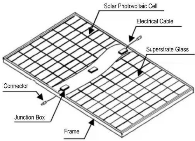
- COMPONENTS
3. GENERAL INFORMATION
(INCLUDING WARNING AND SAFETY)
The installation of PV modules requires a great degree of skill and should only be performed by a qualified licensed professional, including licensed contractors and licensed electricians. Please be aware that there is a serious risk of various types of injury occurring during the installation including the risk of electric shock. All SHARP PV modules are equipped with a permanently attached junction box that will accept variety of wiring applications or with a special cable assembly for ease of installation, and they do not require special assembly.
GENERAL WARNING
- PV modules are heavy. Handle with care.
- Before you attempt to install, wire, operate and maintain the PV module, please make sure that you completely understand the information described in this INSTALLATION MANUAL.
- Contact with electrically active parts of a PV module such as terminals can result in burns, sparks and lethal shock whether the PV modules are connected or not.
- PV modules produce electricity when the sufficient sunlight or other sources illuminate the PV module surface. When the PV modules are connected in series, voltage is cumulative. When the PV modules are connected in parallel, current is cumulative. As a result, a large-scale PV
system can produce high voltage and current which could present an increased hazard and may cause serious injury or death.
- Do not connect the PV modules directly to the loads such as motor since the variation of the output power depending on the solar irradiation causes damage for the connected motor.
1: In the case of a brushless motor, the lock function becomes active and the hall IC is most likely to be damaged.
2: In the case of a brush type motor, the coil is most likely to be damaged.
- In case of snow build-up, snow would slide easier on the smooth surface of the PV module than other parts of the roof. Snow may suddenly slide, fall off the roof and hit nearby objects/areas. Take preventive measures (e.g. snow stopper) when there is possible risk such case would cause an injury or a damage.
GENERAL SAFETY
-
Consult local codes and other applicable laws concerning required permits on regulations for installation and inspection requirements.
-
Before installing a PV module, contact appropriate authorities to determine permit, installation and inspection requirements that should be followed.
-
Install PV modules and ground frames in accordance with applicable rules and regulations.
-
PV modules should be installed and maintained by qualified personnel. Only installer/servicer personnel should have access to the PV module installation site.
-
No matter where the PV modules are installed, either roof mounted construction or any other type of structures above the ground, appropriate safety practices should be followed and required safety equipment should be used in order to avoid possible safety hazards. Note that the installation of some PV modules on roofs may require the addition of fireproofing, depending on local building/fire codes.
-
In the case that the PV modules are non-integral type, the PV module is to be mounted over a fire resistant roof.
-
Use PV modules with the same cell size within series.
-
Follow all safety precautions of other components that are used in the system.
-
In order to avoid a risk of injury or electrical shock, do not allow anyone to approach the PV module if the person has little knowledge on PV module or on the measures that should be taken when PV modules are damaged.
-
Do not shade portions of the PV module surface from the sunlight for a long time. The shaded cell may become hot (hot spot phenomenon) which results in solder joints peeling off. Shading causes drop in generated power and/or operation failure of the PV modules.
-
Do not clean the glass surface with chemicals. Do not let water collect on the glass surface for a long time. This creates a risk of white efflorescence (glass disease) which may result in the deterioration of energy generation.
-
Do not install the PV module horizontally. It may cause dirt or white efflorescence (glass disease) due to water.
-
Do not cover the water drain gap of the frame. There is a risk of frost damage when the frame is filled with water cumulation.
-
If there is a risk of sliding snow, an appropriate measure has to be taken so that PV module frames on lower edge of PV modules will not be damaged.
-
Do not expose PV module to sunlight concentrated with mirrors, lenses or similar means.
-
Turn off inverters and circuit breakers immediately, should a problem occur.
-
In case the glass surface of a PV module is broken, wear goggles and tape the glass to keep the broken pieces in place.
-
A defective PV module may generate power even if it is removed from the system. It may be dangerous to handle the PV module while exposed to sunlight. Place a defective PV module in a carton so PV cells are completely shaded.
-
In case of series connection, the maximum open circuit voltage must not be greater than the specified maximum system voltage. The voltage is proportional to the number of series. In case of parallel connection, please be sure to take proper measure (e.g. fuse for protection of PV module and cable from over current, and/or blocking diode for prevention of unbalanced strings voltage) to block the reverse current flow. The current may easily flow in a reverse direction.
-
Keep PV modules away from children.
HANDLING SAFETY
-
Do not cause an excessive load on the surface of PV module or twist the frame. The glass surface can easily break.
-
Do not stand or step on the PV module. The surface glass of PV module is slippery.
-
Do not hit or put excessive load on the glass or back sheet. The PV cell is very thin and can be easily broken.
-
Do not scratch or hit at the back sheet. The back sheet is vulnerable.
-
Do not damage the junction box or do not pull the cables. The junction box can crack and break.
-
Never touch junction box or the end of output cables with bare hands when the PV module is irradiated. Cover the surface of PV module with cloth or other suitable sufficiently opaque material to isolate the PV module from incident light and wear rubber gloves when handling the wires to avoid electric shock.
-
Do not scratch the output cable or bend it with force. The insulation of output cable can break and may result in electricity leakage or shock.
-
Do not pull the output cable excessively. The output cable may unplug and cause electricity leakage or shock.
-
Do not drill holes in the frame. It may compromise the frame strength and cause corrosion.
-
Do not scratch the insulation coating of the frame (except for grounding connection). It may cause corrosion of the frame or compromise the framework strength.
-
Do not touch the PV module with bare hands. The frame of PV module has sharp edges and may cause injury.
-
Do not drop PV module or allow objects to fall down on the PV module.
-
Do not concentrate sunlight artificially on the PV module.
-
Do not hold the PV module on one side. The frame may bend or twist. Hold the PV module at opposite sides.
INSTALLATION SAFETY
-
Always wear protective head gear, insulating gloves and safety shoes (with rubber soles). Do not wear metallic jewellery to prevent electric shock during installation.
-
Keep the PV module packed in the carton until installation.
-
Do not touch the PV module unnecessarily during installation. The glass surface and the frames get hot. There is a risk of burn, or electric shock.
-
Do not work under rain, snow or windy conditions.
-
Use dry insulated tools
-
Do not drop tools or hard objects on PV modules
-
When working at heights, wear a safety belt and take care not to drop any items (e.g., PV module or tools).
-
Make sure flammable gases are not generated near the installation site.
-
Completely cover the PV module surface with an opaque material during PV module installation and wiring.
-
Plug in the connector tight and ensure the wiring work. Make sure that the connectors have been locked by a snap-in latch. Any treatments over the connectors which may allow to unlock the snap-in latch shall not be done.
-
Due to the risk of electrical shock, do not perform any work if the terminals of PV module are wet.
-
Do not touch the junction box and the end of output cables, the cable ends (connectors), with bare hands during installation or under sunlight, regardless of whether the PV module is connected to or disconnected from the system.
-
Do not unplug the connector if the system circuit is connected to a load.
-
Do not stomp on the glass at work. There is a risk of injury or electric shock if glass is broken.
-
Do not work alone (always work as a team of 2 or more people).
-
Do not damage the back sheet of PV modules when setting the equipotential bonding by bolts.
-
Do not damage the surrounding PV modules or mounting structure when replacing a PV module.
-
Bind cables by the insulation locks. Drooping down of cables from the junction box could possibly cause various problems such as animal biting, electricity leakage in puddle.
-
Take proper measures for preventing the laminate (consisted of resin, cells, glass, back sheet, etc.) from dropping out of the frame in case the glass is broken.
-
Plastic components such as cables or connectors shall be located so that they will not be exposed to direct sunlight after installation to prevent degradation of them.
-
If batteries are used with PV modules, follow safety precautions of the battery manufacturer.
-
In case of extreme snow build-up, the weight of the snow may cause the PV module's frame to deform. Take
appropriate preventive measures to minimize any possible resulting damage.
4. SITE SELECTION
In most applications, the PV modules should be installed in a location where there is no shading throughout the year. In the Northern Hemisphere, the PV modules should typically face south, and in the Southern Hemisphere, the PV modules should typically face north.
Please make sure that there are no obstructions in the surroundings of the site of installation. TAKE PROPER STEPS in order to maintain reliability and safety, in case the PV modules are used in areas such as: Heavy snow areas / Extremely cold areas / Strong wind areas / Installations over, or near, water / Areas where installations are prone to salt water damage/corrosive gas environment/ Small islands or desert areas.
The results of the ammonia test and the salt-mist-corrosion test on the PV modules, carried out under such strict test conditions, should be disclosed for reference purposes only. The decision on whether the PV modules are suitable and compatible for each installation field will depend on the user's judgement and responsibility.
5. TILT ANGLE
The tilt angle is the measurement between the PV module and a horizontal ground surface. The PV module generates the maximum output power when it faces the sun directly.
5 degrees or more is recommended for the tilt angle of the PV module for the maintenance. (See 9. Maintenance)
For the standalone systems with a battery where the PV modules are attached to a permanent structure, the tilt angle of the PV modules should be determined to optimize the performance when the sunlight is the scarcest. In general, if the electric power generation is adequate when the sunlight is the scarcest, then the angle chosen should be adequate during the rest of the year. For grid-connected installations where the PV modules are attached to a permanent structure, it is recommended to tilt the PV module at the angle equal to the latitude of the installation site so that the power generation from the PV module will be optimum throughout the year.
6. WIRING
To ensure proper system operation and to maintain your guaranty, observe the correct cable connection polarity (Figures 1 & 2) when connecting the PV modules to a battery or to other PV modules. If not connected correctly, the bypass diode could be destroyed.
PV modules can be wired in series to increase voltage. Connect wires from the positive terminal of one PV module to the negative terminal of the next PV module. Figure 1 shows PV modules connected in series.
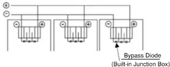
Connect PV modules in parallel to increase current. Connect wires from the positive terminal of one PV module to the positive terminal on the next PV module. Figure 2 shows PV modules connected in parallel.
Figure 1. SERIES for more voltage
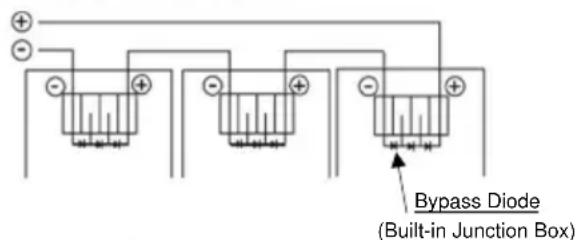
Figure 2. PARALLEL for more current
7. GROUNDING
The frame grounding must consider the local requirement and regulation at the installation site. When grounding is required, please refer to below example connection (Figure 3). Please be careful in arranging the system ground so that the removal of one PV module from the circuit will not interrupt the grounding of any other PV modules.
The PV modules should be grounded to the same electrical point as described below.
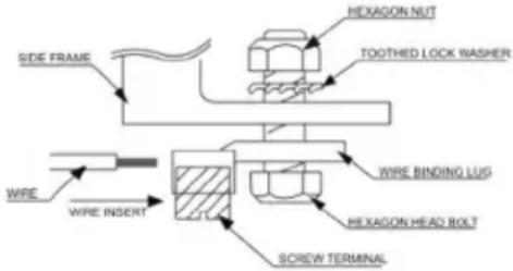
Figure 3. Example of acceptable ground connection
You can use a hole with the appropriate symbol for equipotential bonding on the side frame for either a bolt, nut and washer grounding the PV module to the frame, a ground lug fastened by bolt or screw, or appropriate screw (hardware not provided). An example of acceptable ground connection using a bolt, nut and washer retaining a ground lug is shown in Figure 3. In a connection of this type, the hardware (such as a toothed locked washer / star washer) must score the frame surface to make positive electrical contact with the frame. The ground wire must be considered within the local requirement of local and regulation at the site of installation.
8. MOUNTING
Please make sure that all the information described in the INSTALLATION MANUAL is still valid and proper for your installation. The mounting method has been verified by SHARP and NOT CERTIFIED by a third party organization.
The approved way to mount SHARP PV modules to a support structure is described in this INSTALLATION MANUAL.
Although SHARP does not specify or warrant frame clips or clamps, using frame clips (not provided) or clamps (not provided) is possible when they are designed for PV modules and with minimum dimensions on the sides of the PV module in accordance with the instructions and drawings provided. If using frame clips or clamps, the PV modules should be fixed rigidly and there shall be no damage to the PV modules by deforming mounting structure against design load.
The SHARP PV module guaranty may be void if customer-selected frame clips are improper or inadequate for PV module properties (including strength or material) or installation. Note that if metal clips are used, there must be a path to ground from the clips, (for instance, using star washers in the clip hardware set). Please review the descriptions and drawings carefully; not mounting the PV modules according to one of these methods may void your guaranty. The PV module has passed the test sequence which contains 3 cycles each performed at 5,400 Pa positive and 2,400 Pa negative loading in accordance with IEC61215-2.
Support structures that PV modules are mounted on should be rigid. SHARP PV modules are designed to ensure optimal electrical performance under the condition that they are mounted on rigid support structures. Deformation of support structure may damage PV module with its electric performance.
When mounting the PV module on structure, ensure that no corner has a displacement of more than 2mm per every 1000mm of the diagonal. The mounting structure shall enable the PV module to deflect freely under wind and/or snow load not to make direct impact to the center of the PV module. (i.e. min. 10 cm from the roof surface to the bottom face of PV module frame)
9. MAINTENANCE
The PV modules are designed for long life and require very little maintenance. If the angle of the PV module is 5 degrees or more, normal rainfall is sufficient to keep the PV module glass surface clean under most weather conditions. If dirt build-up becomes excessive, use only a soft, damp cloth and water to clean the glass. If cleaning the back of the PV module is required, take utmost care not to damage the back side materials. In order to ensure the operation of the system, check the connection of wiring and the state of the jacket of wires occasionally.
For PV modules with anti-reflective coating glass, do not touch the glass since finger prints or stains will easily mark. If dirt build-up becomes excessive, clean the glass surface with water only.
INSTALLATION INSTRUCTIONS -PHOTOVOLTAIC MODULES-
1. INSTALLATION
The mounting method has been verified by SHARP and NOT CERTIFIED by a third party organization. Please review the descriptions and drawings carefully; not mounting the PV modules according to one of these methods may void your guaranty.
(Design load according to IEC61215 is 2,400Pa positive and 1,600Pa negative)
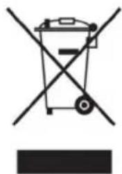
Mounting Using Clips: Clamping on Longer Frame (Figure2)
The PV modules can be mounted using clips (clamps) designed for PV modules as defined in the following Figures. Note that the mounting clips should meet the required dimensions as defined in the Figure1. Note that the CLIP CENTER POSITION (e) is important as specified in the Figure2. The PV module must be supported on the array system and should overlap the array rail by at least 10mm. The array rails must support the bottom of the frames and must be continuous piece (no breaks in the rail).
2. ELECTRICAL INSTALLATION INSTRUCTION
CABLE requirement
Conductor size: 4.0mm² Min.
Cable type: XLPE cable (H1Z2Z2-K cable)
Maximum DC voltage: 1.5kV
Rating temperature: -40°C to +90°C
Maximum conductor temperature:120°C
PV module configuration (Recommend)
# Maximum series configuration: please refer to Table-1 (This value is calculated under the condition of Voc at -40 °C.)
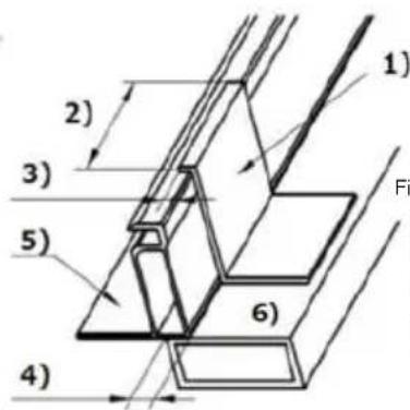
3) Covering depth (7 mm Min. on the frame)
4) Supporting depth (10 mm Min.)
5) Frame (applicable to all frame sections)
6) Array rail
(applicable to parallel or crossed mounting)
# Maximum parallel configuration: (Parallel connection of each string shall be conducted with following two options. Any other parallel connections are prohibited.)
a) Case of using the diodes; 1 diode per maximum 2 parallel strings (Connect a diode or more in series for every string or every 2 parallel strings for protection of PV module from reverse current over load.)
b) Case of using the fuses; 1 fuse per every string (Connect a fuse for every single string for protection of PV module from reverse current over load.)
CONNECTOR requirement
The PV module shall be mated to the same connectors; No connectors shall be cut from the electrical cable.
Type: C1
Brand: Solargiga Energy Holdings Limited
3. WARNING
Keep all PV MODULES and electriacal CONNECTORS clean & dry before installation.
4. Disposal
Dispose PV modules properly. For Information about the proper disposal, contact your local recycling site.
natural_image
Symbol of a trash bin crossed with no visible text or labels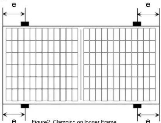
300 mm < e < 400 mm
e: span from PV module corner to clip center
ELECTRICAL OUTPUT AND THERMAL CHARACTERISTICS
Rated electrical characteristics are within ±10 percent of the indicated values of Voc, Isc and +5/-0 percent of Pmax (power measurement tolerance: ±3%), under STC (standard test conditions) (irradiance of 1000W/m ^-2 , AM 1.5 spectrum, and a cell temperature of 25°C (77°F)).
Table-1. Electrical characteristics
| Model name | Max imum Power (Pmax) | Tolerance | Open-Circuit Voltage (Voc) | Short-Circuit Current (Isc) | Voltage at point of max. Power (Vmpp) | Current at point of max. Power (lmpp) | Max imum system voltage | Over-Current Protection | Class for protection against electrical shock | Max imum series configuration(*) |
| NU-JB395 | 395W | +5%/-0% | 49.45V | 10.35A | 41.07V | 9.62A | 1,500V | 20A | II | 25 |
* The maximum series number of modules depends on the local conditions. These values are calculated under the condition of Voc at -40 °C.
Under normal conditions, a PV module is likely to experience conditions that produce more current and/or voltage than reported at Standard Test Conditions. Accordingly, the values of Isc and Voc marked on this PV module should be multiplied by a factor of 1.25 when determining component voltage ratings, conductor capacities, fuse sizes and size of controls connected to the PV module output.
The PV module has been qualified in an environmental temperature range of -40^ to +40^ and up to 100% relative humidity as well as rain, and the altitude up to 2,000m in accordance with IEC61730.
Class for protection against electric shock
This PV module is classified as "Class II" according to IEC61730. These PV modules are intended for installation where geeral user access and contact to insulated live parts is anticipated.
FIRE RATING
This PV module is rated as "Fire safety class C" according to IEC61730-2:2004 or UL790.
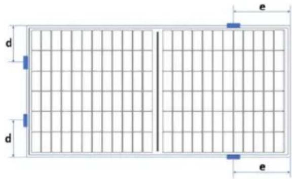
Confirmation of mounting positions for SHARP Solar Modules NU-JBxxx
Sharp Electronics GmbH confirms, that the above-mentioned Module series could be mounted with clamps under below described conditions as an extension of the actual Installation Manual. Furthermore, the test load according Mechanical Load Test (MQT16) of EN61215-2 is 2.400Pa. The installation manual attached to the Modules remains valid. The Product- and Power Output Guarantee in the version at the date of purchase by the end user remains valid. Damages caused by mechanical overload are excluded from the Product Guarantee.
L: 2.008mm
e: 0-502mm
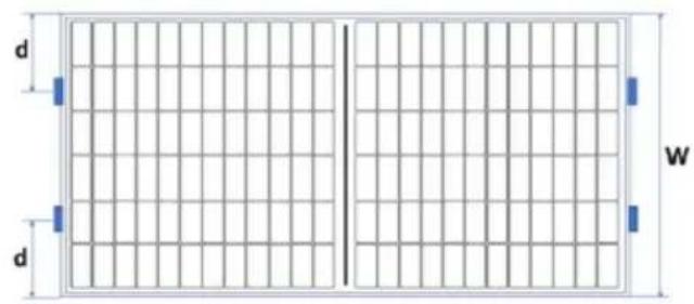
W: 1.002mm
d: 0 - 250mm
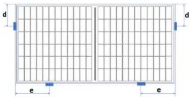
d: 0 - 250mm
e: 0 - 502mm
d: 0 - 250mm
e: 0 - 502mm
This confirmation is valid for Modules with the above-mentioned type designation, that will be sold by Sharp Electronics GmbH until 31 ^st December 2021.
Hamburg, 24.01.2020
P. Thiu
Glcus Gclg
Peter Thiele
President
Klaus Schaefer
Manager Solar Service Support Department
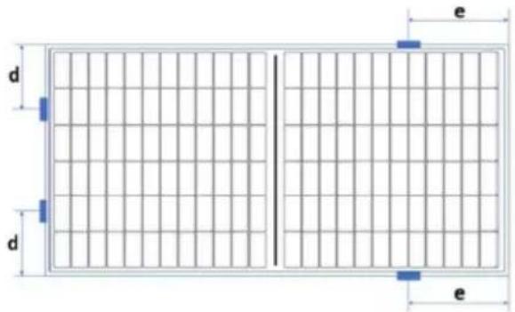
W: 1.002mm
d: 0 - 250mm
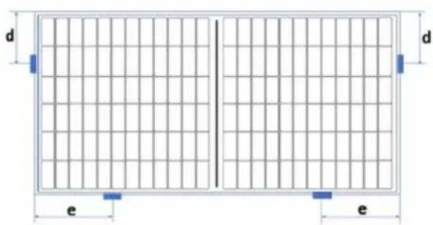
d: 0 - 250mm
e: 0 - 502mm
d: 0 - 250mm
e: 0 - 502mm
Manager Solar Service Support Department


- INSTALLATION MANUAL – Crystalline Photovoltaic Module –
- IMPORTANT SAFETY INSTRUCTIONS
- GENERAL INSTRUCTIONS
- INTRODUCTION
- GENERAL INFORMATION
- (INCLUDING WARNING AND SAFETY)
- GENERAL WARNING
- GENERAL SAFETY
- HANDLING SAFETY
- INSTALLATION SAFETY
- SITE SELECTION
- TILT ANGLE
- WIRING
- GROUNDING
- MOUNTING
- MAINTENANCE
- INSTALLATION INSTRUCTIONS -PHOTOVOLTAIC MODULES-
- INSTALLATION
- Mounting Using Clips: Clamping on Longer Frame (Figure2)
- ELECTRICAL INSTALLATION INSTRUCTION
- CABLE requirement
- PV module configuration (Recommend)
- CONNECTOR requirement
- WARNING
- Disposal
- ELECTRICAL OUTPUT AND THERMAL CHARACTERISTICS
- Class for protection against electric shock
- FIRE RATING
- Confirmation of mounting positions for SHARP Solar Modules NU-JBxxx
Brand : SHARP
Model : NU-JB395
Category : Installation solaire