
FiX 82 - Audio/video converter JL Audio - Free user manual and instructions
Find the device manual for free FiX 82 JL Audio in PDF.


| Product Type | OEM Integration DSP (Audio/Video Converter) |
| Brand | JL Audio |
| Model | FiX 82 |
| Dimensions (L x W x H) | 5.19 in x 4.29 in x 1.85 in (132 mm x 109 mm x 47 mm) |
| Operating Voltage | 10 – 16V DC |
| Current Draw (Operating) | 0.7 A at 13.8V |
| Standby Current Draw | < 1.5 mA |
| Recommended Fuse | 1A, Fast-Acting ATO/ATC |
| Number of Input Channels | 8 (Differential-Balanced) |
| Input Range | 250 mV – 30V RMS |
| Number of Output Channels | 2 (Analog RCA and Optical Toslink) |
| Maximum Analog Output Voltage | 4V RMS |
| Output Impedance (Analog) | 450 ohms |
| Signal-to-Noise Ratio | 96 dB (A-Weighted, referred to 4V RMS) |
| THD + Noise | 0.02% at rated output (20 Hz – 20 kHz) |
| Digital Processor | Intersil D2Audio DAE-6, 24-bit/48 kHz |
| EQ Bands | 30 x 2 channels, 1/3 octave (25 Hz – 20 kHz) |
| Turn-On Modes | Remote (12V trigger), DC Offset Sensing, Signal Sensing |
| Additional Features | Automatic summing, EQ restoration, time-delay correction; JLID port for optional DRC-100 remote; USB firmware update |
| Maintenance | Keep dry and well-ventilated; no user-serviceable parts |
| Safety | Install away from airbags; secure mounting; disconnect battery before installation; protect wires from sharp edges |
| Spare Parts and Repairability | No user-serviceable components; contact authorized JL Audio dealer for service |
| Warranty | 2 years (USA) from original purchase date; non-transferable |
Frequently Asked Questions - FiX 82 JL Audio
User questions about FiX 82 JL Audio
0 question about this device. Answer the ones you know or ask your own.
Ask a new question about this device
Download the instructions for your Audio/video converter in PDF format for free! Find your manual FiX 82 - JL Audio and take your electronic device back in hand. On this page are published all the documents necessary for the use of your device. FiX 82 by JL Audio.
USER MANUAL FiX 82 JL Audio
FiX™ 82
OEM Integration DSP
Thank you for purchasing a JL Audio FiX ^™ OEM interface / processor for your automotive sound system.
This product has been designed and manufactured to exacting standards in order to ensure years of musical enjoyment in your vehicle. For maximum performance, we highly recommend that you have your FiX™ 82 installed by an authorized JL Audio dealer. Your authorized dealer has the training, expertise and installation equipment to ensure optimum performance from this product without compromising your vehicle's functionality. Due to the complexity of modern vehicle systems, we do not recommend self-installation unless you have extensive experience in automotive electrical systems. Should you decide to install this product yourself, please take the time to read this manual thoroughly to familiarize yourself with its installation requirements and setup procedures.
If you have any questions regarding the instructions in this manual or any aspect of the product's operation, please contact your authorized JL Audio dealer for assistance. If you need further assistance, please contact the JL Audio Technical Support Department at technical@jlaudio.com or call (954) 443-1100 during business hours.
Protect Your Hearing!
We value you as a long-term customer. For that reason, we urge you to practice restraint in the operation of this product so as to not damage your hearing and that of others in your vehicle. Studies have shown that continuous exposure to high sound pressure level can lead to permanent (irreparable) hearing loss. Automotive sound systems are capable of producing such high sound pressure levels. Please limit your continuous exposure at high volumes. While driving, operate your audio system in a manner that still allows you to hear necessary noises to operate your vehicle safely (horns, sirens, etc.).
Installation Applications
This product is designed for operation in vehicles with 12 volt, negative-ground electrical systems. Using this product in systems with positive ground and/or voltages other than 12 volts may result in damage to the product and will void the warranty. This product is not certified or approved for use in aircraft.
Safety Considerations
- Install this product in a dry, well-ventilated location that does not interfere with your vehicle's safety equipment (air bags, seat belt systems, ABS brake systems, etc.).
- Securely mount this product so that it does not come loose in the event of a collision or sudden jolt to the vehicle.
- Check before drilling to make sure that you will not be drilling into a gas tank, brake line, wiring harness or other vital vehicle system.
- Do not run system wiring outside or underneath the vehicle. This is an extremely dangerous practice, which can result in severe damage/injury.
- Protect all system wires from sharp metal edges and wear by carefully routing them, tying them down and using grommets and loom where appropriate.
What's Included
(1) FiX ^TM 82 processor
(1) 5-pin Power Connector plug
(4) 4-pin OEM Analog Input plugs
(4) Mounting screws
(1) FIX ^TM Calibration CD
Product Overview
The FiX ^™ 82 is the ultimate tool for building a great sounding system using the OEM source. Equipped with a powerful 24-bit DSP processor, the FiX ^™ 82 delivers world-class sound and incredible functionality allowing the integration of complex factory source units with aftermarket audio equipment. It combines a level matching, summing preamp with delay and frequency response correction, all housed within a single chassis.
The FiX ^™ 82 may be used to perform the following functions:
- Eight differential-balanced inputs accept virtually any OEM analog audio signal, from low-voltage, line-level to high power, amplified speaker-level, and converts them to digital audio with 24-bit effective resolution.
- Compatible with full-range and band-limited OEM signals, outputs from factory 2-way, 3-way or 4-way stereo systems are automatically summed into a complete, full-range stereo signal.
- Factory filtered or "tuned" signals are automatically restored back to a flat, full-range audio output. These digital-domain corrections can vary from subtle to dramatic, depending on the amount of equalization engineered into the factory audio system.
- Time delayed OEM signals are automatically corrected into a synchronized output.
- A simple calibration process performs signal summing, EQ restoration and time-delay correction tasks automatically.
- Digitally corrected signals can then be sent to your aftermarket signal processors or amplifiers via two methods:
- Analog audio through a stereo pair of low-distortion, 4-volt (RMS) line-level outputs
- Digital audio through an optical (Toslink) output, supporting PCM audio (S/PDIF) 24bit/48kHz
- Differential-balanced input architecture ensures noise immunity and compatibility with most analog output OEM source units or amplifiers.
- Selectable turn-on options for activation include: conventional 12-volt trigger, automatic via Signal-Sensing or automatic via DC Offset-Sensing.
- Provides a dedicated remote turn-on voltage output for activating aftermarket amplifiers or signal processors.
- JLID Controller Port allows connection of the optional DRC-100 Digital Remote Controller (sold separately), adding Master Volume Control, Handsfree Optimization Mode and LED Status Reporting capabilities from the driver's seat.
- USB port provides access to update firmware and advanced options.
The FiX ^™ 82 may be used as a standalone integration device, sending crystal-clear audio to your amplifiers or as a gateway to world-class sound by using it with our TwK ^™ System Tuning DSP (sold separately).
Planning Your Installation
It is important that you take the time to read this manual and that you plan your installation carefully. It is very easy to damage expensive vehicle systems in modern automobiles. Never assume that you have found appropriate wires without consulting a reliable wiring diagram or without performing signal testing with proper test equipment. If you are uncomfortable or unfamiliar with reading diagrams or testing signals, please enlist the services of your authorized JL Audio dealer to perform the installation.
Installation Procedure/Making Connections
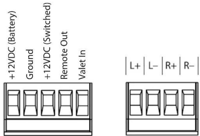
The FiX™ 82 uses removable plugs for making power and signal input connections. Receptacles in each plug accept up to 16 AWG wire. To attach wires to the plug, use a small flathead screwdriver to back out the set screws. Strip 1/4 inch (6 mm) of insulation from the end of each wire and insert the bare wire into the receptacle, seating it firmly so that no wire is exposed. While holding each wire in place, tighten the set screw firmly, taking care not to strip the head of the screw.
! IMPORTANT
Use caution to ensure correct polarity and wire placement of the Power and OEM Input connections.
natural_image
Technical line drawing of a mechanical component with multiple brackets and mounting holes, enclosed in a circular frame (no text or symbols)! IMPORTANT
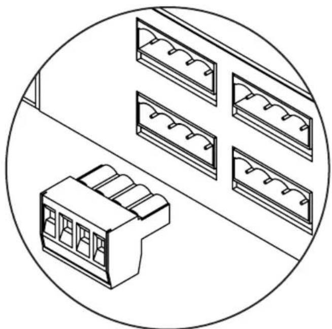
Make sure to observe proper orientation when inserting each plug into the FiX™ 82. Each plug is keyed to fit in one direction only. When inserted correctly, the set screws should be facing down.
Use good quality crimp connectors (or solder with heat shrink tubing) when making connections to a vehicle's electrical system. Protect all wires from sharp edges (metal dash frame, firewall, etc.) by carefully routing and securing them, using grommets and loom where appropriate. Failure to do so may result in a dangerous short circuit.
This page intentionally left blank
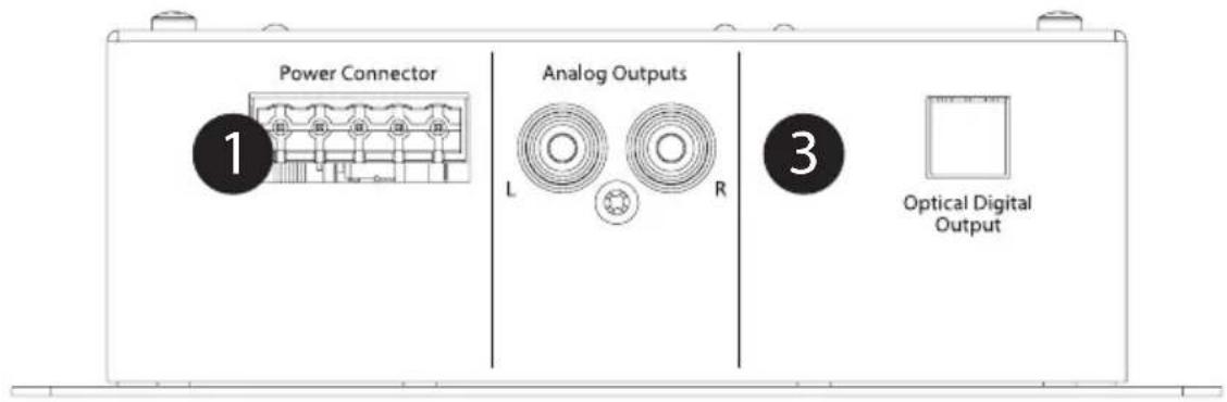
FIX™ 82 Power Connection / Audio Output Panel
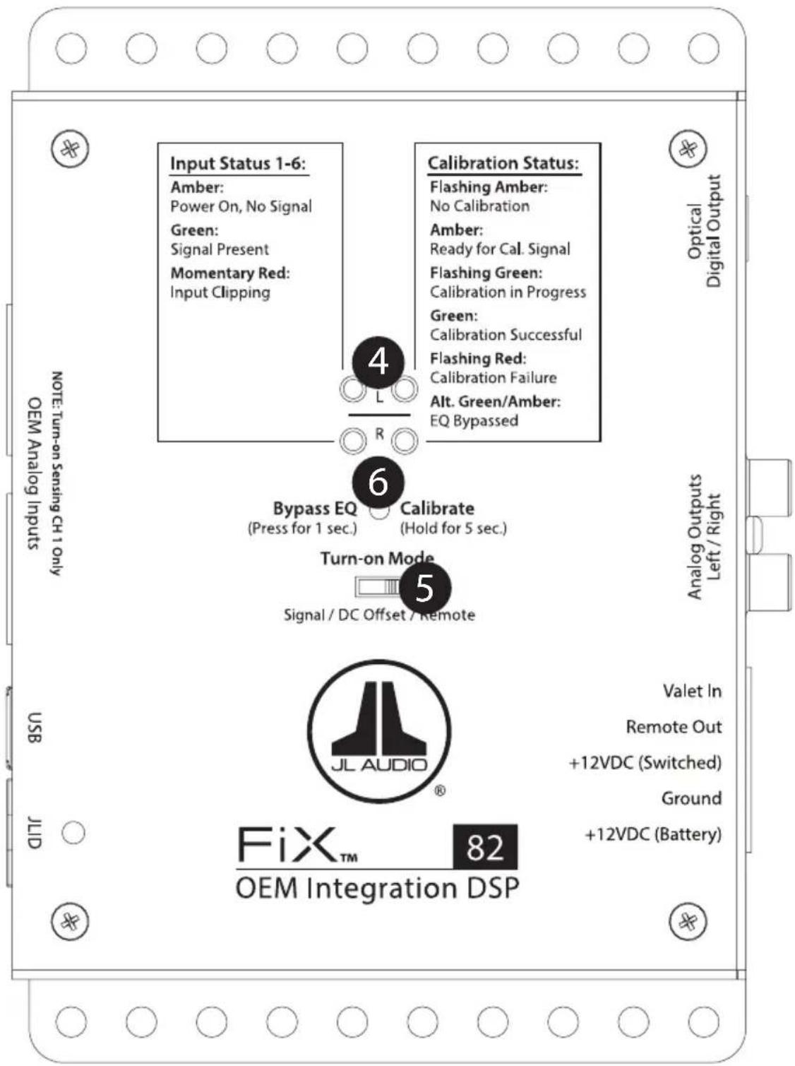
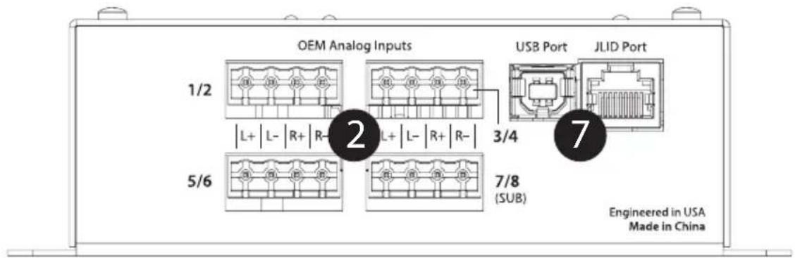
FIX™ 82 Input Panel
1 Power Connections
2 OEM Input Connections
3 Output Connections
4 Status LEDs
5 Turn-On Mode
6 Bypass EQ / Calibrate Button
7 JLID Port and DRC-100 Function
1 Power Connections
The FiX™ 82 has a 5-pin "Power Connector" jack located next to the "Analog Outputs". The Power Connector jack accepts the removable 5-pin plug and is used to make the connections below.
| Plug | Connection Description |
| Power Connector | +12VDC (Battery) Positive (+12V) Power Connection |
| Ground Negative (GND) Ground Connection | |
| +12VDC (Switched) Positive (+12V) Turn-On Input | |
| Remote Out Positive (+12V) Turn-On Output | |
| Valet In Negative (GND) Ground Input (used to activate Valet Mode) |
! IMPORTANT
Never make power connections with a "live" wire. Always disconnect the vehicle's negative battery post before making any connections or adjustments to 12V power connections! Failure to make safe, tight, high-integrity connections can result in fire and extensive damage.
- Disconnect the vehicle's NEGATIVE battery post connection and secure the disconnected cable to prevent accidental reconnection during installation. This is an essential safety precaution during installation!
- +12VDC (Battery): Connect to a constant positive (+12V) source. The internal circuitry of this connection is equipped with a self-resetting fuse designed to protect the unit internally. To protect the vehicle and its electrical system from damage, always install an appropriate fuse within 18 inches (45 cm) of the +12V connection point. If this is the only device using the connection point, we recommend using a 1A fuse.
- Ground: Connect to a clean, solid metal grounding point. Ideally, the +12VDC (Battery) and Ground connections should be run to the same distribution points that the amplifiers use for their power and ground connections. This will minimize the possibility of noise in the system.
- +12VDC (Switched): This connection, along with the "Turn-on Mode" switch setting, determines the turn-on operation of the FiX™ 82. Connect this to the positive (+12V) remote turn-on output of your source unit, if equipped. If your source unit is not equipped with a dedicated remote turn-on output, refer to the "Turn-on Mode" section for more options.
- Remote Out: This connection provides a positive (+12V) turn-on voltage (100 mA limit) to activate other aftermarket signal processors or amplifiers (similar to an aftermarket head unit's remote turn-on lead). If your equipment requires more than 100 mA total for activation, this connection can be used to trigger a relay to control the equipment in your system.
- Valet In: Connect this to negative Ground to activate Valet Mode. When Valet Mode is active, the FiX™ 82's outputs are attenuated by 15 dB and its JLID status LED will flash slow green. Valet Mode can be used to prevent damage to the audio system from unwanted or unauthorized use when your vehicle is being serviced, valet parked, etc. Due to the covert nature of this function, we recommend concealing the location and/or method of its activation. This can be accomplished with a hidden toggle switch (not supplied) or other disguised mechanism to apply negative ground to this connection.
2
OEM Input Connections
The FiX ^™ 82 accepts up to eight channels (four stereo pairs) of full-range or band-limited output from an OEM audio source (250 mV – 30 V RMS). Engineered to combat induced cable noise, the input architecture is set up in a differential-balanced configuration, making these inputs compatible with virtually any analog audio signal. Connections are made via four plugs located on the side of the unit labeled “OEM Analog Inputs”. Each 4-pin plug accepts two channels of audio input, separated in pairs (Left and Right).
Depending on the specific architecture of your OEM system, you will need to locate suitable connection points to provide appropriate input signals to the FiX™ 82, while maintaining OEM functionality. It is recommended to obtain a service manual for the vehicle you are working on to locate and identify the correct OEM wires. Refer to the table below when making connections with your OEM audio source. Note: With most factory audio systems, it is not necessary to connect all eight input channels of the FiX™ 82. We recommend using the least amount of inputs needed to create a full-range audio signal.
| Plug Connection Description | ||||
| 1/2 | L+ | Ch. 1 input Negative | (+) Positive Left Channel Signal | Ch. 1 is the monitored channel for the auto turn-on circuitry. (Make sure Ch. 1 & 2 inputs contain midrange signals.) |
| L-(-) | Left Channel Signal | |||
| R+ | Ch. 2 input Negative | (+) Positive Right Channel Signal | ||
| R-(-) | Right Channel Signal | |||
| 3/4 | L+ | Ch. 3 input Negative | (+) Positive Left Channel Signal | |
| L-(-) | Left Channel Signal | |||
| R+ | Ch. 4 input Negative | (+) Positive Right Channel Signal | ||
| R-(-) | Right Channel Signal | |||
| 5/6 | L+ | Ch. 5 input Negative | (+) Positive Left Channel Signal | |
| L-(-) | Left Channel Signal | |||
| R+ | Ch. 6 input Negative | (+) Positive Right Channel Signal | ||
| R-(-) | Right Channel Signal | |||
| 7/8 (SUB) | L+ | Ch. 7 input Negative | (+) Positive Left Channel Signal | If the OEM subwoofer signal is mono (one ch. only), connect it to both the left and right channels, in parallel. |
| L-(-) | Left Channel Signal | |||
| R+ | Ch. 8 input Negative | (+) Positive Right Channel Signal | ||
| R-(-) | Right Channel Signal | |||
! IMPORTANT
It is very easy to damage expensive vehicle systems in modern automobiles. Never assume that you have found appropriate wires without consulting a reliable wiring diagram or without performing signal testing with safe test equipment. If you are uncomfortable with reading diagrams or testing signals, please enlist the services of your authorized JL Audio dealer to perform the installation.

OEM Input Connections continued...
! IMPORTANT
It is vital to observe the correct electrical polarity of each channel's input signal. Failure to do so can result in improper calibration, loss of signal and poor performance.
Some factory audio amplifiers employ a load detection circuit that looks for a low-impedance load (expecting a speaker) in order to enable audio output. When a high-impedance load like the input section of the FiX™ 82 is connected to these factory amplifiers, the audio outputs will mute.
After installing the FiX™ 82 and turning on the audio system, if there is no output from the factory amplifier, a FiX-LSA-4 Load-Sensing Adaptor (sold separately) will need to be inserted inline with the FiX™ 82's inputs. The FiX-LSA-4 presents a safe and appropriate load to the factory amplifier and corrects the muting behavior. Refer to the FiX-LSA-4 manual for detailed instructions.

Output Connections
The FiX ^™ 82 offers two output types to feed audio signals to your aftermarket system. Choose the output type that is appropriate for the specific equipment of your audio system.
Analog Outputs: Two RCA-type, 4-volt (RMS) line-level output jacks are located next to the "Power Connector" and are labeled for each channel (Left and Right). Analog outputs are compatible with most types of aftermarket signal processors or amplifiers. The level of this output is proportionate to the FiX™ 82's input signal and may also be controlled by the optional DRC-100 Digital Remote Controller (sold separately).
Optical Digital Output: Located next to the "Analog Outputs", this jack provides a digital audio output that is not susceptible to RF interference or noise-generating electrical conditions. This digital output is intended for use with a TwK™ System Tuning DSP (sold separately) or other signal processors or amplifiers that have an optical (Toslink) digital audio input (S/PDIF) jack. The level of this output is proportionate to the FiX™ 82's input signal and is not affected when used with the optional DRC-100 Digital Remote Controller (sold separately). For remote level control, you may use the DRC-200 Digital Remote Controller that is included with the TwK™ System Tuning DSP (sold separately).

Status LEDs
Located on top of the unit are two sets of LEDs used to report the status of the FiX™ 82. Arranged in left (L) and right (R) pairs, the LEDs are divided by category (Input Status and Calibration Status) and may be referenced during setup, calibration and normal use. Refer to the markings above the LEDs for specific behavior definitions.
The FiX ^™ 82 is designed to perform as a turn-on and turn-off controller for the aftermarket components in your system. There are three options to control its method of turn-on, which can be selected via the “Turn-on Mode” switch located on the top of the FiX ^™ 82. Refer to the table below for detailed info and decide which option is best suited for your specific system.
| Setting Mode Function | +12VDC (Switched) Connection | Note | ||
| Remote | Conventional (Preferred) | Controlled by your source unit for turn-on and turn-off control. | Connect to your source unit's +12V remote turn-on output. | If your source unit does not have a dedicated remote turn-on output, use the DC Offset or Signal setting below. |
| DC Offset | DC Offset Sensing (Auto)* | Automatically turns on and off by detecting the presence of small DC signal in OEM audio outputs. | Connect to a positive (+12V) source. This can be to the same connection point as the FiXTM 82's +12VDC (Battery) connection or to a positive (+12V) accessory circuit that is controlled by the vehicle's ignition switch. | If your source unit is controlled by a RAP (Retained Accessory Power) circuit, connect the +12VDC (Switched) connection to a positive (+12V) accessory circuit that is controlled by the vehicle's ignition switch. This will maintain the RAP functionality. |
| Signal | Signal Sensing (Auto)* | Automatically turns on by detecting full-range OEM audio signals and turns off after signal is removed (varies, depending on input signal levels). | ||
| *When using DC Offset or Signal Sensing Modes, make sure Ch. 1 & 2 inputs of the OEM Analog Inputs contain midrange signals. | ||||
Bypass EQ / Calibrate Button
The Bypass EQ/Calibrate button located on top of the unit is used to initiate the calibration procedure or to deactivate the FiX™ 82's equalization functions. Refer to the following info and table at right for specific instructions.
Bypass EQ: The Bypass EQ mode can be used to defeat the equalization effects of the FiX™ 82, allowing you to hear the raw response of the OEM audio source. Pressing the Bypass EQ button for 1 second will activate the Bypass EQ mode. As a visual confirmation, the Calibration Status LEDs will alternate green/amber. The Bypass EQ mode will remain engaged for 5 minutes or until you press the button again.
Calibrate: Use the calibration procedure to perform signal summing, EQ restoration and time delay correction tasks automatically. Once all connections are made, follow the steps in the "Calibration Process Chart" to perform the calibration procedure.
! IMPORTANT
Ensure that any vehicle chimes or alerts that play through the audio system are not triggered during the calibration process.
Calibration Process Chart
| Action | Input Status LEDs | Calibration Status LEDs | Note |
| 1. Turn on source unit and confirm the FiXTM 82 and all aftermarket equipment have turned on. | When the FiXTM 82 is powered, its Input Status LEDs are active and their illumination will vary depending on the condition of the input signal. | Flashing amber (only if it has never been calibrated) | OEM source unit balance, fader and tone controls should be set to zero/ flat or "centered". Turn off any source unit EQ or DSP modes. |
| 2. With the OEM source unit volume set at 75%, insert the FiXTM Calibration CD and play Track 01. (Note: Track 01 begins with 20 seconds of silence.) | If your OEM source unit is not equipped with a CD player, you may transfer the calibration track to a portable media player or thumb drive and connect to your source unit's auxiliary input. Make to sure to disable any EQ/DSP modes on your portable media player during calibration. | ||
| 3. Within 15 seconds of starting Track 01, press and hold the "Calibrate" button for 5 seconds until the "Calibration Status" LEDs turn to steady amber, then release. | Two green flashes | Once the "Calibrate" button is released, the "Calibration Status" LEDs may also light amber, depending on the progress of Track 01. This is normal. | |
| 4. After approximately 30 seconds, the "Calibration Status" LEDs will indicate whether a successful calibration was achieved or not. | Steady green Successful calibration | ||
| 1 short red flash* | Error: Calibrated response not flat | ||
| 2 short red flashes* | Error: Incomplete audio spectrum | ||
| 3 short red flashes* | Error: Delay compensation failure | ||
| 4 short red flashes* | Error: No or low input signal level | ||
| *Refer to the "Troubleshooting" section for more info. | |||
Calibration Reset
If desired, the calibration memory of your FiX™ 82 may be reset to an original "factory" state. This may be useful during troubleshooting or when transferring equipment from one vehicle to another. To reset the calibration memory of your FiX™ 82: Press and hold the "Calibrate" button for 15 seconds until the "Calibration Status" LEDs begin to alternate green, then release the button. The "Calibration Status" LEDs will cycle through amber-red-green colors x 3 times, then flash amber to confirm the reset status.

JLID Port and DRC-100 Function (optional)
The JLID port is designed to allow connection of the optional DRC-100 Digital Remote Controller (sold separately). Connecting a DRC-100 to the FiX ^™ 82 will add remote Master Volume Control, Handsfree Optimization and LED Status Reporting features to the FiX ^™ 82. Since these are driver-controlled functions, we recommend mounting the DRC-100 within easy reach of the driver, on the center console or dashboard of the vehicle. (Refer to the installation instructions included with the DRC-100 for detailed info.)
Master Volume Control: When used as a Master Volume Control, the DRC-100 maintains linear frequency response at all volume levels and delivers the best signal-to-noise performance for your audio system. To use, leave the volume control of your OEM source unit at the specific volume position that was used during calibration. From now on, you will use the DRC-100 to control your audio system volume, leaving the OEM volume control at the calibration level. You may continue to use the OEM source unit's tone, balance and fader controls, if desired.
Handsfree Optimization: The FiX™ 82 includes a Handsfree Mode designed to optimize the audio clarity of your vehicle's handsfree telephony system, if equipped. When Handsfree Mode is activated, the FiX™ 82's time correction function is disabled and a 100 Hz high-pass filter is applied to the audio outputs. Press the DRC-100 control knob once to activate Handsfree Mode. The DRC-100 status LED and the JLID LED on the FiX™ 82 will both illuminate amber to signify that Handsfree Mode is activated. When the call is finished, press the DRC-100 control knob again to deactivate Handsfree Mode, returning the color of the LEDs back to green.
LED Status Reporting: The DRC-100's multi-color LED will illuminate to report the FiX™ 82's overall condition to the driver. Refer to the table below for the color and meaning of the LED's behavior.
| LED Color Status/Condition | |
| Constant green Normal operation | |
| Slow green flash Valet mode is active | |
| Constant amber Handsfree mode is active | |
| Flashing or constant red Clipped input signal detected* | |
| *Reduce output level of the source unit |
Troubleshooting
| Problem Possible Cause Possible Solution | ||
| FiX doesn't turn on | Faulty fuse | Remove fuse and check with continuity meter. Replace if necessary. |
| Poor connection integrity | Check "Ground" and both "+12VDC" connections for pinched wires; ensure tight connections. | |
| Insufficient "+12VDC (Switched)" input | Make sure there is a sufficient +12V supply at the "+12VDC (Switched)" connection; if not, a relay may be required. | |
| Incorrect auto turn-on mode settings | Verify "+12VDC (Switched)" and input signal connections; refer to "Turn-On Mode" section. | |
| Amps or processors not turning on | Poor connection integrity | Check "Remote Out" connections for pinched wires; ensure tight connections. |
| Little or no bass response | Handsfree mode is engaged | Deactivate Handsfree mode using DRC-100, if equipped. |
| Reversed polarity at one or more inputs | Double-check wiring of "OEM Analog Inputs". | |
| Low or no volume | OEM source unit/master volume set too low | Increase OEM source unit volume; increase DRC-100 master volume control, if equipped. |
| Calibration Error Possible Cause Possible Solution Before Recalibration Attempt | ||
| 1 short red flash: Calibrated response not flat | OEM source unit tone/EQ controls not set flat | Verify OEM source unit tone controls are set to zero/flat or "centered" and turn off any source unit EQ or DSP modes. |
| Reversed polarity at one or more inputs | Double-check wiring of "OEM Analog Inputs". | |
| 2 short red flashes: Incomplete audio spectrum | Disconnected or incorrect input connections in multi-way system | Connect input plugs, 1 pair at a time, and check for green "Input Status" LEDs when playing Calibration Track 01. |
| Use RTA to view output spectrum to identify response gap for correction. Attempt to "Fill the gap" by substituting a different L/R channel pair and recalibrate. | ||
| 3 short red flashes: Delay compensation failure | Poor connection integrity | Double-check "OEM Analog Input" plugs for open or loose connections. |
| Elevated OEM system noise floor | Disconnect any redundant input plugs already carrying audio content available via other input plugs and recalibrate. | |
| Recalibrate at a lower (or higher) OEM source unit volume setting. | ||
| 4 short red flashes: No/low input signal level | OEM source unit volume set too low | Increase OEM source unit volume and recalibrate. |
| Valet mode is engaged Ensure Valet mode is not active. | ||
| Too low or missing signal from OEM outputs | Make sure "Input Status" LEDs are green during audio playback. With multiple inputs, insert input connectors one plug at a time (input channels 1/2, 3/4, 5/6, 7/8) while playing a calibration test signal and confirm both L & R "Status LEDs" are green during playback. | |
| Verify the OEM outputs are "on". The OEM source unit may need to "see" a speaker load to turn the amp "on". | May need to install a FiX-LSA-4 (sold separately) to activate OEM amp outputs. | |
Specifications
| Electrical Specifications | |
| Power Supply Type | Regulated DC-DC SMPS |
| Operating Voltage | 10 – 16V DC |
| Standby Mode Current Draw | < 1.5 mA |
| Operating Current Draw | 0.7 A at 13.8V |
| Recommended Fuse Value | A |
| Recommended Fuse Type | Fast-Acting, ATO/ATC or similar |
| OEM Input Section | |
| Number of Input Channels | Eight |
| Input Type | Differential-Balanced |
| Input Range | 250 mV – 30V RMS |
| Input Level Setting | Fully Automatic |
| Input “Signal Present” Threshold | 10 mV RMS |
| Digital Specifications | |
| Processor | Intersil® D2Audio DAE-6 |
| Bit Depth / Sample Rate | 24 bit / 48 kHz |
| Number of EQ Bands | 30 x 2 channels |
| EQ Resolution | 1/3 octave (25Hz – 20kHz) |
| Output Section | |
| Number of Output Channels | Two |
| Output Type | Unbalanced, via RCA Jacks |
| Optical digital (S/PDIF) | |
| Maximum Output Voltage | 4V RMS |
| Output Impedance | 450 ohms |
| Signal to Noise Ratio | 96dB (A-Weighted, referred to 4V RMS output) |
| THD + Noise | 0.02% at rated output (20Hz – 20kHz) |
| Dimensions | |
| L x W x H | 5.19 in. x 4.29 in. x 1.85 in. (132 mm x 109 mm x 47 mm) |
Limited Warranty – Electronics (USA)
JL Audio warrants this product to be free of defects in materials and workmanship for a period of two (2) years from the original date of purchase. This warranty is not transferrable and applies only to the original purchaser from an authorized JL Audio dealer. Should service be necessary under this warranty for any reason due to manufacturing defect or malfunction, JL Audio will (at its discretion), repair or replace the defective product with new or remanufactured product at no charge. Damage caused by the following is not covered under warranty: accident, misuse, abuse, product modification or neglect, failure to follow installation instructions, unauthorized repair attempts, misrepresentations by the seller. This warranty does not cover incidental or consequential damages and does not cover the cost of removing or reinstalling the unit(s). Cosmetic damage due to accident or normal wear and tear is not covered under warranty.
Warranty is void if the product's serial number has been removed or defaced.
Any applicable implied warranties are limited in duration to the period of the express warranty as provided herein beginning with the date of the original purchase at retail, and no warranties, whether express or implied, shall apply to this product thereafter. Some states do not allow limitations on implied warranties, therefore these exclusions may not apply to you. This warranty gives you specific legal rights, and you may also have other rights, which vary from state to state.
If you need service on your JL AUDIO product:
All warranty returns should be sent to JL Audio's Electronics Service Facility freight-prepaid through an authorized JL Audio dealer and must be accompanied by proof of purchase (a copy of the original sales receipt). Direct returns from consumers or non-authorized dealers will be refused unless specifically authorized by JL Audio with a valid return authorization number. Warranty expiration on products returned without proof of purchase will be determined from the manufacturing date code. Coverage may be invalidated as this date is previous to purchase date. Non-defective items received will be returned freight-collect. Customer is responsible for shipping charges and insurance in sending the product to JL Audio. Freight damage on returns is not covered under warranty.
For Service Information in the U.S.A. please call JL Audio Customer Service:
(95 4) 443-110 0 9:00 AM – 5:30 PM (Eastern Time Zone)
JL Audio, Inc. 10369 North Commerce Pkwy. Miramar, FL 33025 (Do not send product for repair to this address)
International Warranties:
Products purchased outside the United States of America are covered only by that country's distributor and not by JL Audio, Inc.

- FiX™ 82
- OEM Integration DSP
- Protect Your Hearing!
- Installation Applications
- Safety Considerations
- What's Included
- Product Overview
- The FiX ™ 82 may be used to perform the following functions:
- Planning Your Installation
- Installation Procedure/Making Connections
- ! IMPORTANT
- Power Connections
- 2
- OEM Input Connections
- OEM Input Connections continued...
- Output Connections
- Status LEDs
- Bypass EQ / Calibrate Button
- Calibration Reset
- JLID Port and DRC-100 Function (optional)
- Limited Warranty – Electronics (USA)
- Warranty is void if the product's serial number has been removed or defaced.
- If you need service on your JL AUDIO product:
- For Service Information in the U.S.A. please call JL Audio Customer Service:
- International Warranties:
Brand : JL Audio
Model : FiX 82
Category : Audio/video converter