
Nautic NSB6V1 - Soundbar MB QUART - Free user manual and instructions
Find the device manual for free Nautic NSB6V1 MB QUART in PDF.


| Type | Soundbar |
| Brand | MB Quart |
| Model | Nautic NSB6V1 |
| Dimensions (L x D x H) | 21.02 x 4.92 x 4.33 inches (534 x 125 x 110 mm) |
| Weight | 12.9 lbs (5.9 kg) |
| Number of Speakers | 6 |
| Power Input | 12V DC (Red wire), Ignition (Orange wire), Ground (Black wire) |
| Bluetooth | Yes, Bluetooth 5.0 (estimated) |
| Auxiliary Input | 3.5mm AUX IN |
| Audio Output | Yes (for additional speakers, if applicable) |
| Controls | Power, Volume Up/Down, Track Forward/Backward, Play/Pause, Map Light/Illumination |
| Mounting Options | Roll cage (clamps for 1.5, 1.75, 2 inch tubes) and Surface mount (L brackets) |
| Water Resistance | Marine grade, suitable for wet environments (IPX6 estimated) |
| Map Light | Built-in map light with illumination settings |
| Warranty | 1 year from date of purchase (limited) |
| Package Includes | Soundbar, top tube clamps (6), channel slide lugs (2), tube clamp bases (2), screws (M5X10 and M5X20), surface mount brackets (2) |
| Compatible Vehicles | Off-road vehicles, boats, UTVs, and other marine applications |
| Recommended Professional Installation | Yes, for optimal performance and safety |
| Remote Output | Blue wire - Remote Out (for amplifier turn-on) |
| Input Switching | Quick press power button toggles between Bluetooth and AUX |
Frequently Asked Questions - Nautic NSB6V1 MB QUART
User questions about Nautic NSB6V1 MB QUART
0 question about this device. Answer the ones you know or ask your own.
Ask a new question about this device
Download the instructions for your Soundbar in PDF format for free! Find your manual Nautic NSB6V1 - MB QUART and take your electronic device back in hand. On this page are published all the documents necessary for the use of your device. Nautic NSB6V1 by MB QUART.
USER MANUAL Nautic NSB6V1 MB QUART
natural_image
Technical line drawing of a multi-tiered electronic device with circular components and a central connector (no text or symbols)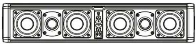
natural_image
Technical line drawing of a multi-pin electronic device with six circular speakers (no text or symbols)Nautic NSB6V1 / NSB10X11 Soundbars
Congratulations on your choice of MB Quart Nautic Sound Bars. This “Quick Start” Installation guide is meant to help you complete a basic installation. For more detailed information about the product, please visit our website at MBQuart.com
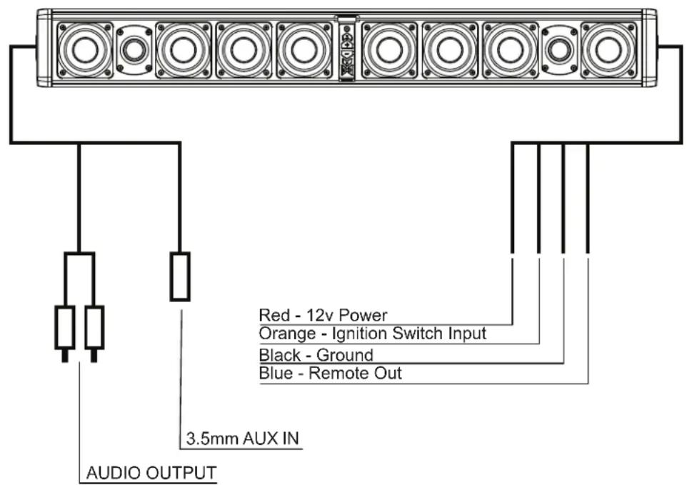
Wiring
The wiring and connections should be secure and away from any moving parts or extremely hot surfaces.
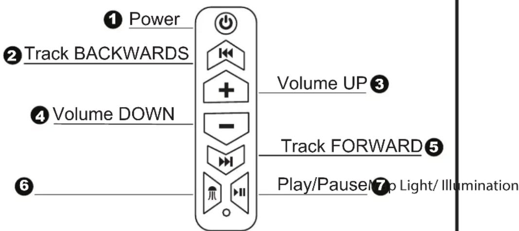
Controls
1 Power - Will turn the unit on or off / Five second hold/ quick push will switch inputs.
2 Track BACKWARDS - Press to restart the current track or to back up to previous tracks.
③ Volume UP - Each press will increase the volume.
4 Volume DOWN - Each press will decrease the volume.
5 Track FORWARD - Press to advance to the next track.
6 Map Light / Illumination - Turn on Map Light, cycle through illumination settings.
7 PLAY / PAUSE - Press once to pause. Press again to play.
Bluetooth Device Pairing
The pairing process can vary based on your particular device. Refer to the operating instructions of your device. Below is the general process to connect.
During unit power up, the blue LED on the bottom of the control panel will blink indicating that it is in Bluetooth search mode.
During this process "MB Quart" should show up in your list of Bluetooth devices when the search has connected with your device. When the connection is made the blue LED will change to a solid color.
Once a device has been paired, the unit will reconnect at power up to that device when in range.
To connect to a different device, the first device will need to be disconnected.
When a phone call is received, the audio signal will mute but not disconnect.
To switch to 3.5mm press the power button quickly.
To switch back to BT press the power button again quickly.



MBQuart.com
#MUSIC DEFINED
WARRANTY
Maxxsonics USA Inc. warrants this product, to the original consumer purchaser, to be free from defects in material and workmanship for a period of one (1) year from the date of purchase. Maxxsonics USA Inc. will, at its discretion, repair or replace defective products during the warranty period. Components that prove to be defective in materials and workmanship under proper installation and use must be returned to the original authorized Maxxsonics USA Inc. retailer from where it was purchased. A photocopy of the original receipt must accompany the product being returned. The costs associated with removal, re-installation and freight are not the responsibility of Maxxsonics USA Inc. This warranty is limited to defective parts and specifically excludes consequential damages connected therewith. To view the full warranty, please visit the website.
any incidental or
MB Quart products are designed and engineered in the USA by
MAXXSONICS®
www.maxxsonics.com
SOUND BAR MOUNTING
The following is intended to help you mount the sound bar. We highly recommend employing the expertise of a professional installer.
The sound bar has two convenient installation styles. Roll Cage and Surface Mount review this document to determine which you will use, then prepare for installation.
A. Prepare a flat work surface to prepare for installation
B. Recruit an assistant to help with lifting Sound Bar into place
C. Use lightweight painters tape to cover your roll cage while you are positioning
INCLUDED PARTS
| NUMBER | DESCRIPTION | QUANTITY INCLUDED |
| 1 | Top Tube Clamp(1.5, 1.75 or 2 inch options) | 6 |
| 2 | Channel Slide Lug | 2 |
| 3 | Tube Clamp Base | 2 |
| 4 & 5 | M5X10 Screws(Top & Bottom Clamps)(Clamp Bottom to Channel Slide Lug) | 12 |
| 6 | Surface Mount Bracket | 2 |
| 7 | M5X20 Screws for “L” Brackets | 2 |
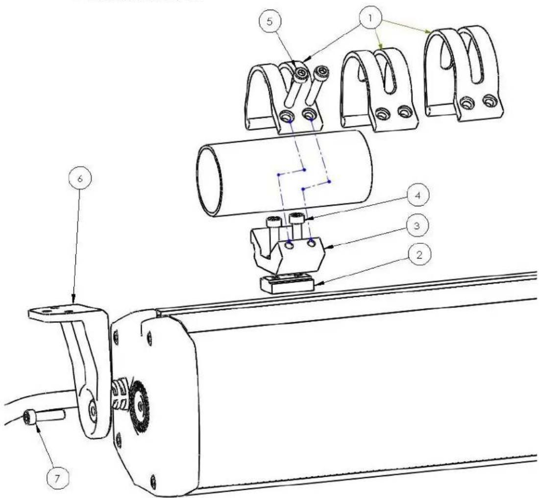
FIG 1-1
INSTALL STEPS - Surface Mount (L Brackets)
Reference the illustration FIG 1-1 to confirm which components are needed for each STEP. Items on the list are called out with brackets [X].
STEP 1 - Mount 1 Surface Mount Bracket [6] per side with the longer [7] M5x20 screws.
STEP 2 - Position the Sound Bar in place. Use a marker to identify where the mounting holes will be located on your vehicle. Use at least 2 of the 3 holes to mount the sound bar. Confirm there are no moving parts or wires on the other side of your mounting surface. Consider drilling a small pilot hole.
STEP 3 - Mount the Sound Bar*
* These mounting screws are not included as different off-road or marine applications will vary.
INSTALL STEPS - Roll Cage
Reference the illustration FIG 1-1 to confirm which components are needed for each STEP. Items on the list are called out with brackets [X].
STEP 1 - Choose the appropriate Top Tube Clamp [1] for your roll cage diameter. We have included 1.5, 1.75 and 2 inch clamps.
STEP 2 - Insert 2 slide lugs [2] into the mounting channel on top of the sound bar. You want these lugs to be left and right in the channel.
NOTE – Use some lightweight painters tape to mark where you will want the clamping system on the left right side of your roll cage. The following assembly should remain loose until you know you have the correct position. Only use hand tools, do not over tighten.
STEP 3 - Mount the Tube Clamp Base [3] to the Channel Slide Lug [2] using two [4/5] M5X10 screws. Make sure to prep both the left and right side of the sound bar. Position the hooked edge of the Clamp Base to the back of the sound bar – screw holes to the front.
STEP 4 - With your assistant lifting the sound bar into position, you will confirm that the wires on the sound bar are not pinched and remain accessible on both ends.
STEP 5 – With the sound bar still held in the air by your helper, you will use the Top Tube Clamp to lock on the back of the Tube Clamp Base and use two [4/5] M5X10 screws per side (left/right) to mount the sound bar `the roll cage.
NOTE – Use hand tools to secure these screws to avoid damage to the sound bar or the vehicle. Do not fully tighten the screws until you are confident of your positioning.
STEP 5 – Once your positioning is confirmed, use your hand tools to fully tighten the screws on the clamp. Your clamping system should not move left/right. If it is loose, you need to tighten the screws shown in STEP 2.
NOTE – Once the Sound bar is in final position, remove any painter's tape that is visible
STEP 6 - Wire up the sound bar
ADDITIONAL MOUNTING OPTIONS
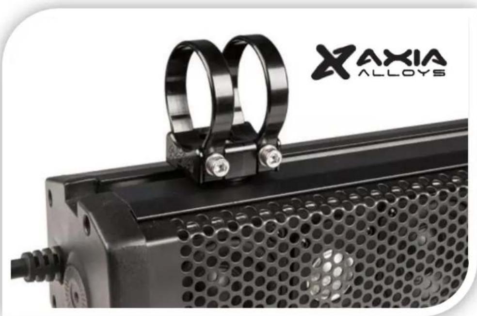
If you find that your installation is more exotic or challenging that can be addressed with the included hardware we recommend our build partner AXIA ALLOYS. They offer a wide variety of billet aluminum mounts mounting system for more accessories that you can possibly install on your vehicle.
natural_image
Close-up of a black industrial machine with two metal rings attached, no visible text or symbols on the device itself.Here is a link for with the components for your sound bar. Make sure to check out all the other mounting creativity from AXIA ALLOYS while you're on the site.
DIMENSIONS & WEIGHT
| MODEL | LENGTH | DEPTH | HEIGHT | WEIGHT |
| 6 Speakers | 21.02 | 4.92 | 4.33 | 12.9 lbs (5.9 kg) |
| 10 Speakers | 34.41 | 4.92 | 4.33 | 21 lbs (9.5 kg) |
Brand : MB QUART
Model : Nautic NSB6V1
Category : Soundbar