
DN-16112 - VCR Digitus - Free user manual and instructions
Find the device manual for free DN-16112 Digitus in PDF.


| Product Type | Network Video Recorder (NVR) |
| Model | DN-16112 |
| Brand | Digitus |
| Channels | 16 |
| Video Resolution | 1080p |
| Network Speed | 10/100/1000 Mbps |
| Video Outputs | HDMI (primary), VGA (secondary) |
| Storage | Supports internal HDD (up to 1 disk, not included); USB backup via FAT32 USB drive |
| Recording Modes | Continuous, Scheduled, Event-triggered, Manual |
| Playback | Synchronized playback up to 4 channels; search by time or event |
| PTZ Control | Yes, via on-screen click; supports preset points and sequences |
| Network Protocols | DHCP, Static IP, DDNS (DynDNS, No-IP) |
| Event Notifications | Email, FTP upload of snapshots and text files |
| E-Map | Local E-Map and Google Maps integration for camera location |
| Firmware Upgrade | Via web UI or USB |
| Power Supply | External power adapter (12V DC, typical) |
| Dimensions (approx.) | 1U rackmount size (44 x 30 x 4.5 cm) |
| Weight (approx.) | 2.5 kg |
Frequently Asked Questions - DN-16112 Digitus
User questions about DN-16112 Digitus
0 question about this device. Answer the ones you know or ask your own.
Ask a new question about this device
Download the instructions for your VCR in PDF format for free! Find your manual DN-16112 - Digitus and take your electronic device back in hand. On this page are published all the documents necessary for the use of your device. DN-16112 by Digitus.
USER MANUAL DN-16112 Digitus
DIGITUS® Professional
NETWORK VIDEO RECORDER 1080p RESOLUTION 10/100/1000 Mbps
4-CHANNEL/8-CHANNEL/ 16-CHANNEL

User Manual
DN-16111 • DN-16112 • DN16113
Table of Contents
Hardware 4
Overview 4
LED & Buttons Definitions 4
Connect to the NVR 4
Use NVR Search Utility 5
Access the NVR with its default IP address 10
Main/Live View 12
a. The UI's 5 main functions:....13
b. Date and Time display 13
c. User's configuration.... 13
d. Hardware events notification 14
e. Channels status.... 14
f. Video frame.... 14
g. List view.... 15
h. 1, 4, 9, 16 Pattern view ...... 16
i. Sequence view.... 16
j. Save view 16
k. Saved view 17
I. Hidden accordion menu 18
Playback view 20
a. Zoom on a range of time 21
b. Minimize the bar of the playback.... 21
c. Certain functions you can perform to the playback video...... 21
d. Take a snapshot of a playback video 21
Event view.... 26
NVR Setup - Settings 28
Display 29
Network Settings.... 30
DHCP Server 32
DDNS Service 32
Time and Date 34
Storage.... 35
Users & privileges 36
Add a new user....36
Change the password of the "admin" account....37
Group Privilege 37
Camera 38
Automatic Search....38
Add a camera manually....44
Recording 45
Scheduling 47
Preset Point Setting 48
PTZ Preset Settings 48
PTZ Preset Sequence 50
OSD Settings 51
Event Sources 53
Event sources....54
Notifications 56
Event actions....58
E-Map 59
Local E-Map Setting....59
Google Map Setting 62
Device Info....64
Log 65
Maintenance 66
Firmware Upgrade....66
Backup & Restore 68
USB backup 69
NVR Media Player 71
Play the backup file with the NVR Media Player.... 71
Open Event Snapshot images with NVR Media Player 76
Hardware
Overview
LED & Buttons Definitions
| LEDs | Status | Definitions |
| Power On | Solid- Power on | |
| Alarm On Blinking | when a system/camera event occurs.each event | |
| None Goes off if reaches the 10-second duration, or when buzzer stop button is pressed(if buzzer is triggered) | ||
| Status On *Solid- | Normal operation | **Blinking after press and hold the reset button for 5 seconds indicates the device will enter the restore default process. Other LEDs remain unchanged during this state.*Blinking during firmware upgrade(web page upgrade or USB upgrade)*Keep blinking for failed firmware upgrade through USB disk or web |
| None | *When system is unable to start properly | |
| Network On | *Solid for activity on a 10/100M/1Gbps network | |
| Buttons | ||
| Manual record ON | Press and hold for 2 seconds | |
| OFF | Press and hold for 2 seconds | |
| Reset Restore default | Press and hold for 10 seconds | |
| Restart | Press and hold for 2-10 seconds | |
| Buzzer stop STOP | Press and release should stop buzzer right away | |
Connect to the NVR
There are various ways you can connect to the NVR and below are the suggested methods for different network setup:
- The NVR is placed in a network with a DHCP server: Connect to the NVR by using "NVR Search" Utility
- The NVR is placed in a network without DHCP server (or you are connecting to it directly): Access the NVR with its default IP
Use NVR Search Utility
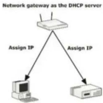

If the NVR is placed in a corporate network or a local area network where a DHCP server is already present, run the "NVR Search" utility from a computer that is on the same network and locate the NVR with its IP address that is assigned by the top-level DHCP server.

To begin, launch the "NVR Search" utility from the CD and proceed with the installation:

Once the installation is complete, check the "Launch the Search AP" option and click "Finish".

The search should start automatically and its status should be displayed.

The NVR should be located and its IP address should be displayed.

Double-click on an NVR and the search program should automatically access the NVR's web administration page from your default browser.
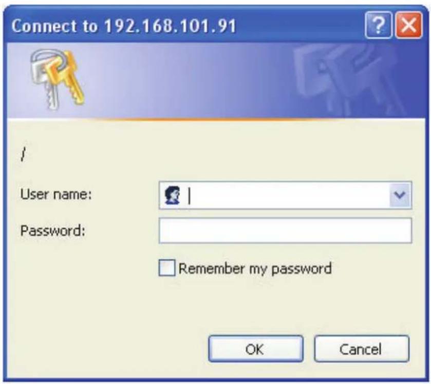
You should be prompted for the NVR's username and password. Enter its default username "admin" and password "admin" and then click "OK" to enter the system.
- Please make sure you are using Internet Explorer 7 or above.
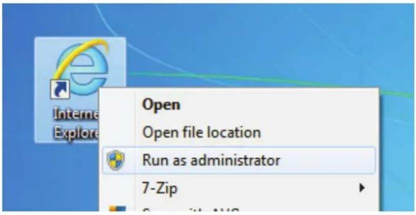
- If you are running Windows Vista or 7, please make sure you are running Internet Explorer with the "administrator" privilege.
Access the NVR with its default IP address.
1.

2.

The NVR comes with a pre-configured static IP "192.168.101.50". However, it is only used when there is no DHCP server present in the network. The NVR will turn on its DHCP server function and act as the DHCP server in the network. To connect to the NVR, use a PC that is on the same network over a switch or hub, or connect the PC directly to the NVR using a crossover CAT5 Ethernet cable.
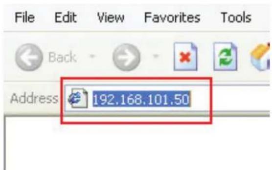
The PC that is connected directly to the NVR (or within the same local area network) should receive an IP from the NVR. Simply access the NVR from your web browser with its IP address.

Again, you should be prompted for the username and password. Enter its default username "admin" and password "admin" and then click "Login" to enter the system.
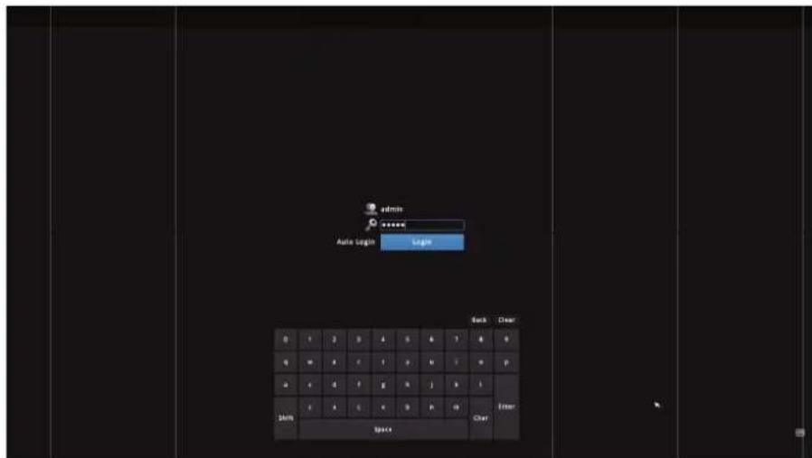
If you use local UI to operate NVR, click display virtual keyboard to enter user name and password.
Main/Live View

The main/live view is the first interface displayed once you access to the NVR through the internet browser.
It displays the live video of all the cameras added to the INVR and following the pattern chosen by the user. The interface has many functions explained bellow.
The "Live View" page provides the following functions:
- Retrieve camera's video stream
- Retrieve camera's status • Perform Live Sequence Viewing • PTZ Control (Click directly on the video) • Perform PTZ Preset Sequence viewing • Perform manual recording
• Take snapshot - as soon as a snapshot selection is made, the snapshots are automatically saved to x:\SnapshotFolder ("x" represents the partition where Windows is installed, e.g: C:)
• Receive audio of a video stream - Send audio • Control "Buzzer" • Change web UI display language
a. The UI's 5 main functions:

The bar displays the 5 main functions of the Web User Interface (UI).
The Live view is the main view .The other 4 views will be explained in each chapter.
b. Date and Time display
Aug 2, 2013 13:43:40
The Date and the Time are defined by the user in the settings section of the NVR.
c. User's configuration

It displays the name of the current user.
If you click on the name of the user, the context menu offers the functions below:
- Language settings
- User settings
- Locking the screen
- Logout function
d. Hardware events notification

In this section, you will receive notifications if a warning sound is triggered or if the hard drive of the NVR failed in recording data.
e. Channels status

If you click on the icon, the page tab will display the current status of the channels added to the NVR.

It can also display the current configuration used for the event recording or the configuration set for the scheduled and manual recording.
The channels status page is updated as long as the NVR's main user interface is open.
f. Video frame
All the camera's videos are displayed in this frame.
- The PTZ function is available by clicking the left button of the mouse on the camera's view.
- Double click on the left button of the mouse enables the zoom function. To disable it, you can click on the right button of the mouse.
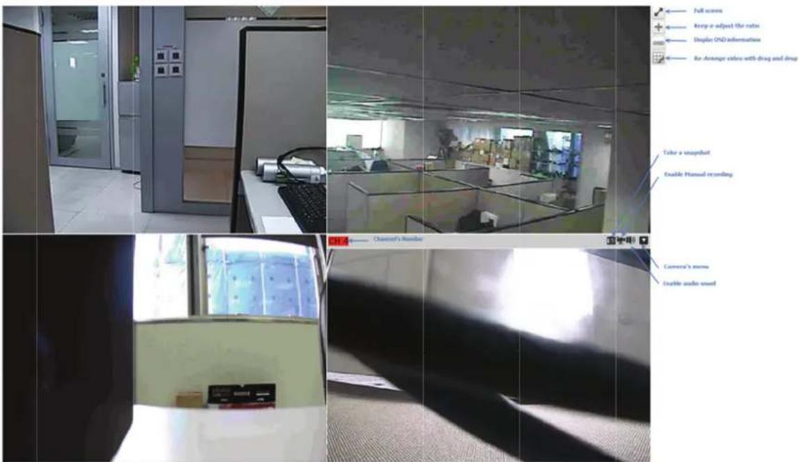
If the cursor is pointing on one of the cameras, it will show a bar at the top.
The bar displays the channel's number and some functions as shown in the snapshot above.
g. List view
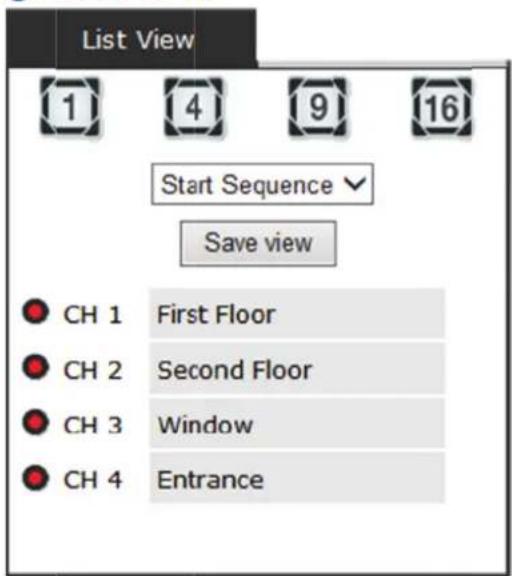
It displays the list of channels added to the NVR. Each channel represents a camera with its name, the channel number, and its current status.
![graph TD A["Channel's number"] --> B["CH 1 First Floor"] C["Channel's status"] --> B D["Channel's name"] --> B](/content/2026/05/805090/images/d9f6b2ab4e02002506b3604ea62fe1b904b5c7e88ab389a14e14810a69691386.jpg)
The channel's status is defined by 3 colors:
- Red: The channel is recording and the live view is available
- Blue: The channel is connected and live view is available
- Grey: The camera is disconnected
h. 1, 4, 9, 16 Pattern view


Different patterns of live view can be displayed on the video frame. You can display 1, 4, 9, or 16 cameras at once.
Every time you click on an "n" pattern icon, the live video of the next "n" cameras will be displayed.
i. Sequence view
| Start Sequence |
| 5s |
| 10s |
| 20s |
| 30s |
| 45s |
| 60s |
The sequence mode will automatically switch between a single or group of cameras every a certain period of time. You can define this period from 1 second to 60 seconds
j. Save view
Save view
Click on the save view button and you will be able to name the current view and save it.
This will help to quickly display your configured views when needed.
k. Saved view

This section can display the views that you have already saved. You can choose the views from the list you have created. You are also able to switch between saved views every certain period of time by clicking on the "start sequence function".
If you check the box beside the name of the view, you can edit or delete the view.
I. Hidden accordion menu
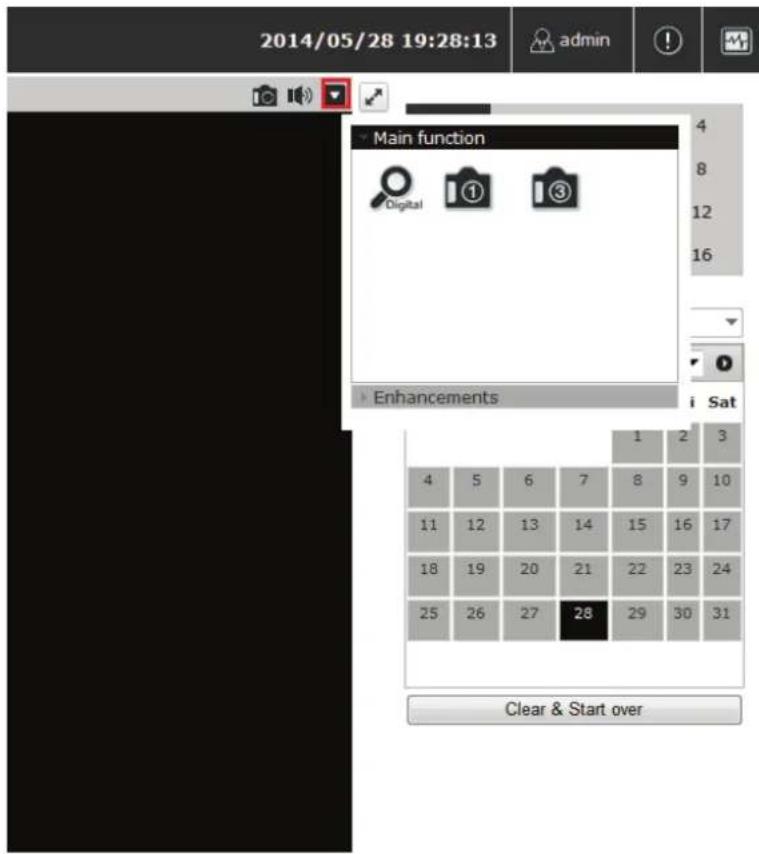
Click button to open accordion menu.

The accordion menu is used to control video channel, the function depends on supported camera.
The functions include main function (digital PTZ, snapshot, audio post), lens control, preset point control, change channel, stream selections, fisheye mode and lens selection.

Main function


- Digital PTZ On/Off (Default: Off)
- Take a snapshot
- Take 3 consecutive snapshots
- Audio post (should be in disabled state if camera doesn't support this function)
If multi-stream mode of camera is supported by NVR, you can select the suitable video stream to be displayed.

Playback view
Playback is a function that allows you to play one or more videos that were previously recorded by a chosen recording method or due to an event trigger. The NVR offers synchronized playback from up to 4 channels and various types of search methods are provided to help you find the footage you need quickly.
You can turn on or off the audio of a recorded video at your choice if audio was also recorded during the recording of the video.
Playback video can be viewed in full screen and snapshots can be taken and saved during a video playback.

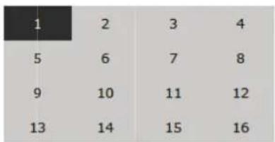
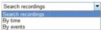
To play a recorded video:
- Select channel
- Choose "search mode", by times or by events
a. Zoom on a range of time
If you click on the icon you can zoom on range of the time and get more details on the playback bar.
b. Minimize the bar of the playback

If you click on the icon you can minimize the playback range to get more space for the videos.
c. Certain functions you can perform on the playback video
You can do the following by right-clicking on the playback video:
- Play Audio
- Snapshot
- Export as AVI file
- Digital PTZ
- Adjust brightness
- Adjust Contrast
d. Take a snapshot of a playback video
To take a snapshot, click on the button "☐", and a manual will show up. You are given options to take 1 snapshot or 3 continuous snapshots.
If the "3 continuous snapshots" option is chosen, the new window displays snapshots and lets you view them individually by using the "Prev" and "Next" buttons shown above.
However, as soon as a snapshot selection is made, the snapshots are automatically saved to x:\SnapshotFolder ("x" represents the partition where Windows is installed, e.g., C:).
You can right-click anywhere on the image and select "Save Picture As..." to save the images somewhere else if you wish.
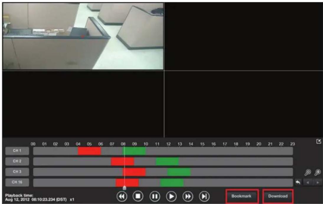
"Bookmark" is used to set a time range for export.
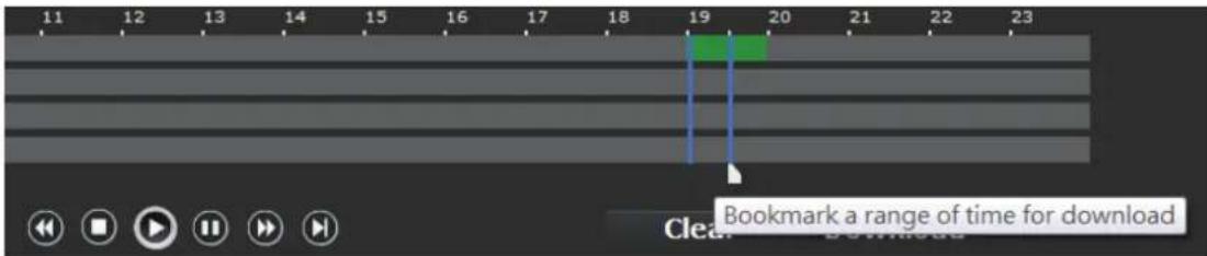
- Click will set the current playback time as "Start" time. A blue slider should be displayed on the timeline.
- Click again will set the current playback time as "end" time. A blue slider should be displayed on the timeline.
Click "Download" to open a pop-up dialog for export options.
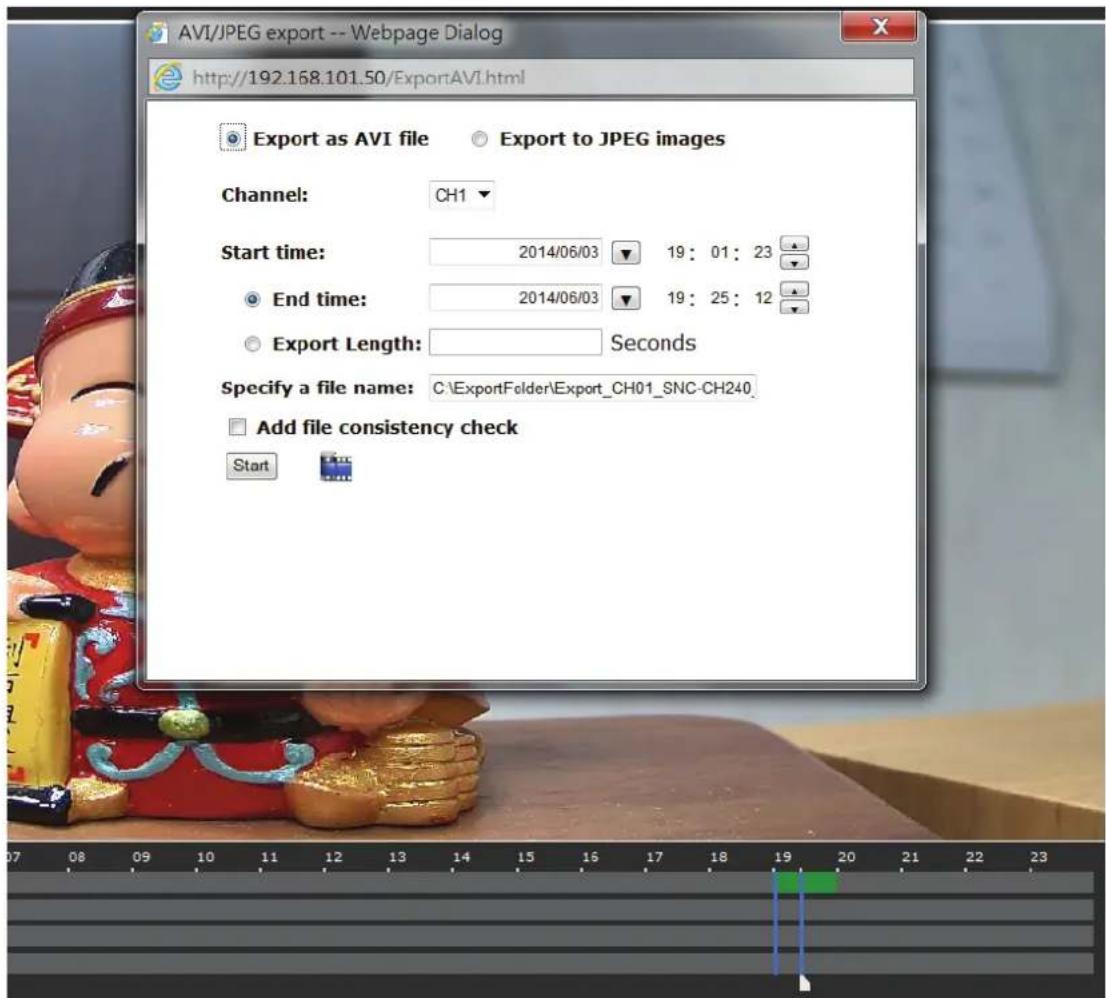
On Web UI

On local UI, the recorded video can be backed up to a USB disk with AVI file. It is required to plug in a USB disk formatted in FAT32 prior to using the backup function. Click "OK" to open a pop-up dialog for USB disk options.

Click "OK" to start backup.


Event view
This section displays the last events recorded by the NVR.
The events can only be detected and displayed if you have configured them on the NVR's settings. You can display the events of all channels at once or by each channel.

You can click on one of the pictures at the bottom of the UI to display the event related to it. The event can also be displayed if you choose them from the list on the right side of the UI.

NVR Setup - Settings
The "Settings" page provides users options to set up the device quickly and properly. There are two modes: basic mode and advanced mode. You just select the mode from the drop-down menu.

Device Configuration

Display

Network

Time & Date

Storage

Users & privileges
Video & Recording Configuration

Cameras

Recording

Scheduling

Preset point

OSD
Event Configuration

Event sources

Notification

E-map
Device Operations

Device info

Log

Maintenance

Backup & Restore

USB Backup
View by: Advance options
Device Configuration

Display

Network

DDNS

DHCP Server

Time & Date

Storage

Users & privileges
Video & Recording Configuration

Cameras

Recording

Scheduling

Preset point

Preset point sequence

05D
Event Configur

Event sources

E-mail notification

FTP notification

Event actions

E-map
Device Operations

Device info

Log

Maintenance

Backup & Restore

USB Backup
After properly configuring all settings in all the sub-pages, users should expect a fully working network video recorder that is ready to manage cameras on the network. We will start by configuring its
network settings to make sure it works correctly in your network. Next, we will help you adjust the system time so videos will be recorded with correct timestamps. To better secure the system from unwanted disturbance, we will guide you on setting up user accounts and privileges to prevent settings from being altered by users other than the system administrator. Lastly, we will tell you what you should expect after installing a hard disk and how to prepare the hard disk for video recording.
Display
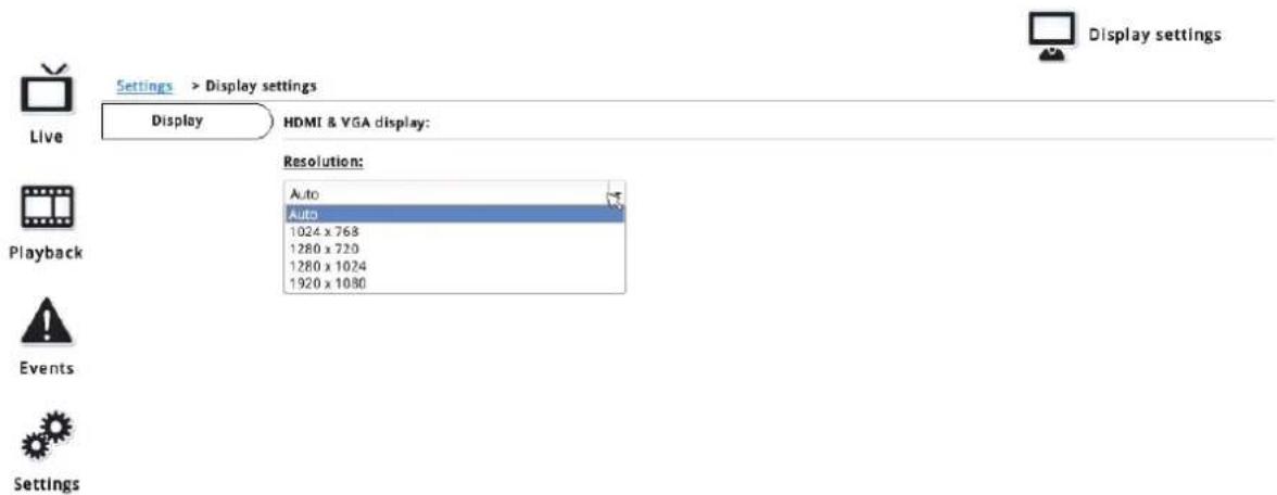
The "Display" configuration page allows you to choose the most optimized display resolution for the monitor that is used with the NVR, as there may be circumstances where the incorrect resolution is used when the system first boots up.
The NVR comes with two video outputs (HDMI: Primary as default, VGA: Secondary as default). The video is the same for both outputs.
NOTE: The NVR will reboot automatically upon change of resolution or monitor for the new setting to take effect or be detected.
Network Settings
Device configuration




Video & Recording configuration


Event configuration


Device operations





Network settings
Settings > Network settings
Connection type
Connection port
DDNS
DHCP server
- Set network automatically (This might enable device to assign IP addresses to other devices on the network) © Get network configuration automatically Use manual configuration
Status: DHCP server On
IP address: 192.168.101.50
Subnet mask: 255.255.255.0
Gateway: 192.168.101.50
DNS 1: 192.168.0.1
DNS 2:
Device name:
The NVR supports three connection types that can be configured depends on how the network is setup:
1. Set network automatically
Set the NVR to configure network settings automatically
1) When no other DHCP server is in the network, the NVR should use the default IP:
192.168.101.50 and turn on built-in DHCP servers
2) Users should not be able to change IP settings when this mode is selected. 3) Users cannot turn on/off the built-in DHCP server.
2. Get network configuration automatically
This sets the NVR as a DHCP client.
1) If no other DHCP server is in the network, the NVR should change to use the auto mode automatically. 2) Users should not be able to change IP settings when this mode is selected. 3) Users cannot turn on/off the built-in DHCP server.
3. Use manual configuration
Set the NVR to use a static IP.
1) The built-in DHCP server should be turned on when this mode is selected. 2) Use the NVR's default static IP when this mode is selected. 3) Users can change the IP settings.
Users can turn on/off the built-in DHCP server.
You need to adjust settings on this page for the device to work properly in your network. It is critical that settings here are configured correctly based on your network configurations so that the recorder can be administered through the local area network and cameras can be connected from it.
By default, the recorder is set to "Set network automatically." If there's a DHCP server in the same local network, the NVR can obtain an IP address from the DHCP server, and you can locate the NVR by using the NVR search utility.
If there's no DHCP server in the network, and the NVR is set to enable the DHCP server, it will use its own default static IP 192.168.101.50.

Network settings
Settings > Network settings

If you wish to set the recorder to use a static IP address in your local area network,
- Choose "Use manual configuration"
- Enter the IP address, subnet mask, default gateway address and DNS server address for the recorder
* The recorder can detect the presence of a DHCP server upon startup. It sets itself to use static IP address if there is no DHCP server currently presented in the network. Its DHCP server function is also turned on at the same time to assign IP addresses to cameras that are later connected to the network or you can manually turn off the DHCP server function if you wish to use a separate DHCP server.
DHCP Server
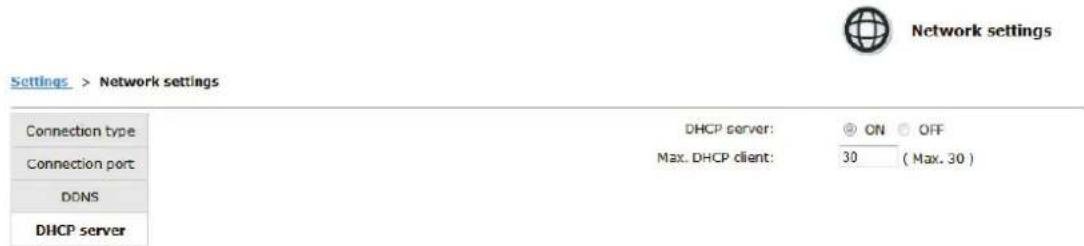
The built-in DHCP Server function is NOT always configurable and is greatly dependent to the connection type that is set to use in "Network Settings".
DDNS Service
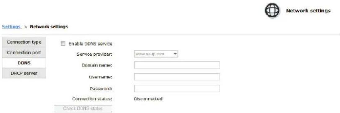
DDNS, which stands for "Dynamic DNS", is a method, protocol, or network service that provides the capability for a networked device, such as a router or computer system (in this case, the NVR) using the Internet Protocol Suite, to notify a domain name server to change, in real time, the active DNS configuration of its configured hostnames, addresses or other information stored in DNS.
A popular application of dynamic DNS is to provide a residential user's Internet gateway that has a variable, often changing, IP address with a well-known hostname resolvable through standard DNS queries. This is useful if the NVR is placed on the Internet with a dynamic public IP, which once the DDNS is properly setup, users can access the NVR remotely with the DDNS domain name without worrying if the IP has changed or not.
*Please make sure a valid DNS server has been configured under the "Network Setting" page in order for this function to work properly.
*The NVR currently works with free DDNS service provided by "DynDNS & No-IP". For more information, please go to www.dyndns.com & http://www.noip.com/
*If the NVR is placed behind a router or Internet gateway, please make sure port forwarding for port 80 is configured on the router or the gateway in order for the DDNS function to properly register with the service. It's often suggested to use the DDNS function in the router/gateway for such case instead.
*Once you have the DDNS function successfully up and running, please DO NOT forget to configure port forwarding for the NVR web port (default 80) and the streaming port (default 9877) in the router/gateway for remote viewing. You can then type in http://yourddnsdomain in the browser to access the NVR remotely for live view.
Time and Date

Time & Date
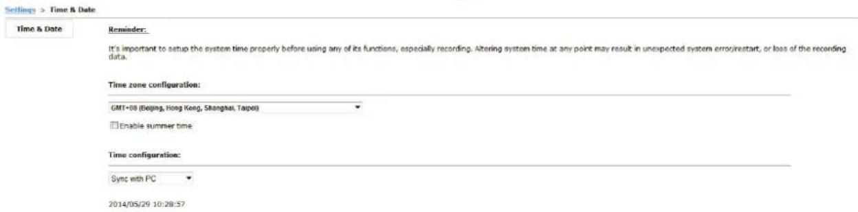
Set the time and date by selecting the time zone according to your location. It is imperative that you set the recorder's time correctly to avoid the following errors:
- Incorrect display time for playback videos
- Inconsistent display time of event logs and when they actually occur. After selecting the time zone, choose an option below to set the recorder time.
Time configuration:

- Sync with NTP server – enter the hostname or IP address of a valid NTP server and set how often the recorder should synchronize the time with it by using the "Update interval" drop-down menu.
Time configuration:
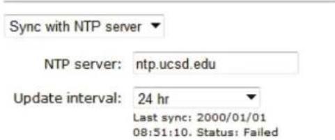
- Configure manual – Use the drop-down list and configure the time manually.
- Sync with PC – Check this option to synchronize the recorder time with the PC that you are currently using to access the recorder.
Storage
Disk actions
Select an action...
Disk list
| Disk ID | Model | Capacity | Remaining space | Online Time | Recording Period | Est. remaining recording time | Status |
| 2 | 469GB | 445GB | 2014/06/03 19:00:41 | 2014/06/03 19:00:53 - 2014/06/03 19:03:00 | -- | Online |
USB disk list
| Disk ID | Capacity | Remaining space | Status |
Once you install a hard disk to the recorder, you would need to initialize it so that it can be ready for recording. You can obtain basic information about the disk you installed in this page.
Disk actions

To initialize it, simply choose the "Format" and disk ID in Disk actions, then click "Apply".
This page will list the internal disks and the USB disk only. The HDD will be formatted in EXT4 file system.
- Disk ID: Displays the disk ID.
- Model: Displays the HDD model name.
- Capacity: Displays the HDD capacity in "GB".
- Remaining space: Displays the remaining space in "GB". • Online Time: Displays when it was formatted.
- Recording Period: Displays the period of time recording took place.
- Est. remaining recording time: Calculates the remaining recording time based on remaining disk space and current cameras' settings. • Status: Displays the HDD status.
Users & privileges

Users & privileges
Settings > Users & privileges
Create new user
Group privileges


User account list

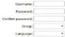
Multiple users can access the recorder simultaneously. You can add, remove, and edit users by using options provided on this page to keep user information organized. Each recorder comes with a built-in "admin" account with password "admin". It's highly recommended to change the password upon your initial login.
Add a new user
Create new user
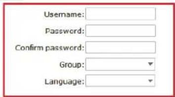
User account list

- Click "Add" to add new user
- Enter a username and password
- Select a group from the "Group" drop-down menu to assign the new user to a particular group
- Click "Apply" to finish configuration
Change the password of the "admin" account
Create new user

User account list

- Click and highlight the "admin" account in the account list and click
- Its information should be displayed
- Enter a new password in the "Password" field and enter it again in "Confirm Password"
Group Privilege
Group Privilege is where you can create multiple customized access policies for situations if you need the recorder to be accessed by users other than the administrator. There are 7 pre-defined user groups for privilege configurations. You can do so by creating a group, and then remove access privileges for certain configuration pages or cameras. Users that are created and assigned to this group will have limited access instead of full administration rights.
The recorder comes with seven built-in groups and five built-in privilege profiles, except the "admin" and the "guest" accounts; the other five groups are fully customizable or you can simply assign a group with one of the default privilege profiles. You can, however, assign more than one users to the "admin" account if you wish to do so. The guest account comes with a "view-only" privilege in the "Live View" page, and users in this group do not have the power to make any changes in the "Live View" page or have access to pages other than the "Live View" page.
To change a group configuration, after clicking "Add" to add a new user account, press "Edit" to change group privileges.
User account list

Group privileges
Group name:
Live videos √ Allow use of PTZ √ Playback videos System settings
admin
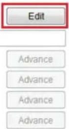
You can change the group name and privileges.
Camera
Automatic Search
Device configuration
Network
Time & Date
Storage
Users & privileges
Video & Recording configuration

Event configuration
Recording
Scheduling
Preset point
OSD
Event sources
Notification
E-map
Device operations
Device info
Log
Maintenance
Backup & Restore
USB Backup

| Channel | Channel name | Camera's IP address | Live stream | Record stream |
| 1 | SNC-CH240 | 192.168.101.10 | H264, 1920x1080 | H264, 1920x1080 |
In "Settings" >> "Cameras", click the "Auto search" button to perform the camera search.
After that, the search should begin and its status should be displayed:

Found cameras should be listed, and simply select a camera from the list.

Camera settings
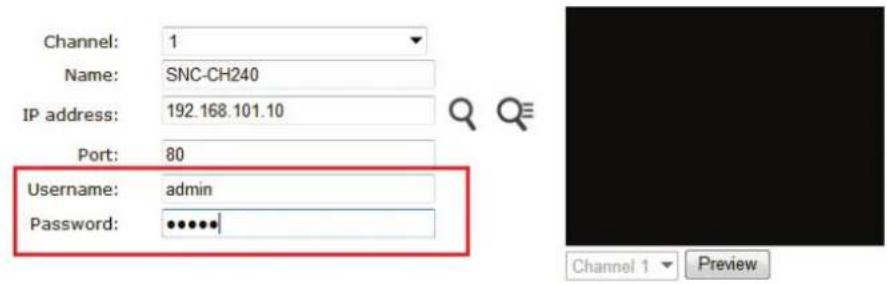
Its corresponding information should be displayed in the "Camera Information" section. Enter its username and password and press "Next" to detect this camera.

If connection establishes successfully, the camera's detailed information should be polled and displayed as below.
Adjust its video format, frame rate, resolution, or bitrate, etc., if you wish.
You can enable "Configure with advance mode" to set up multi-stream if it is supported on this camera.
You will start to set up the 1st video stream, then the 2nd stream, and so on.
Some cameras are capable of four streaming profiles, in which different video codecs are used for different purposes.

After the 1st video stream has been set up, then you can set up the 2nd video stream.
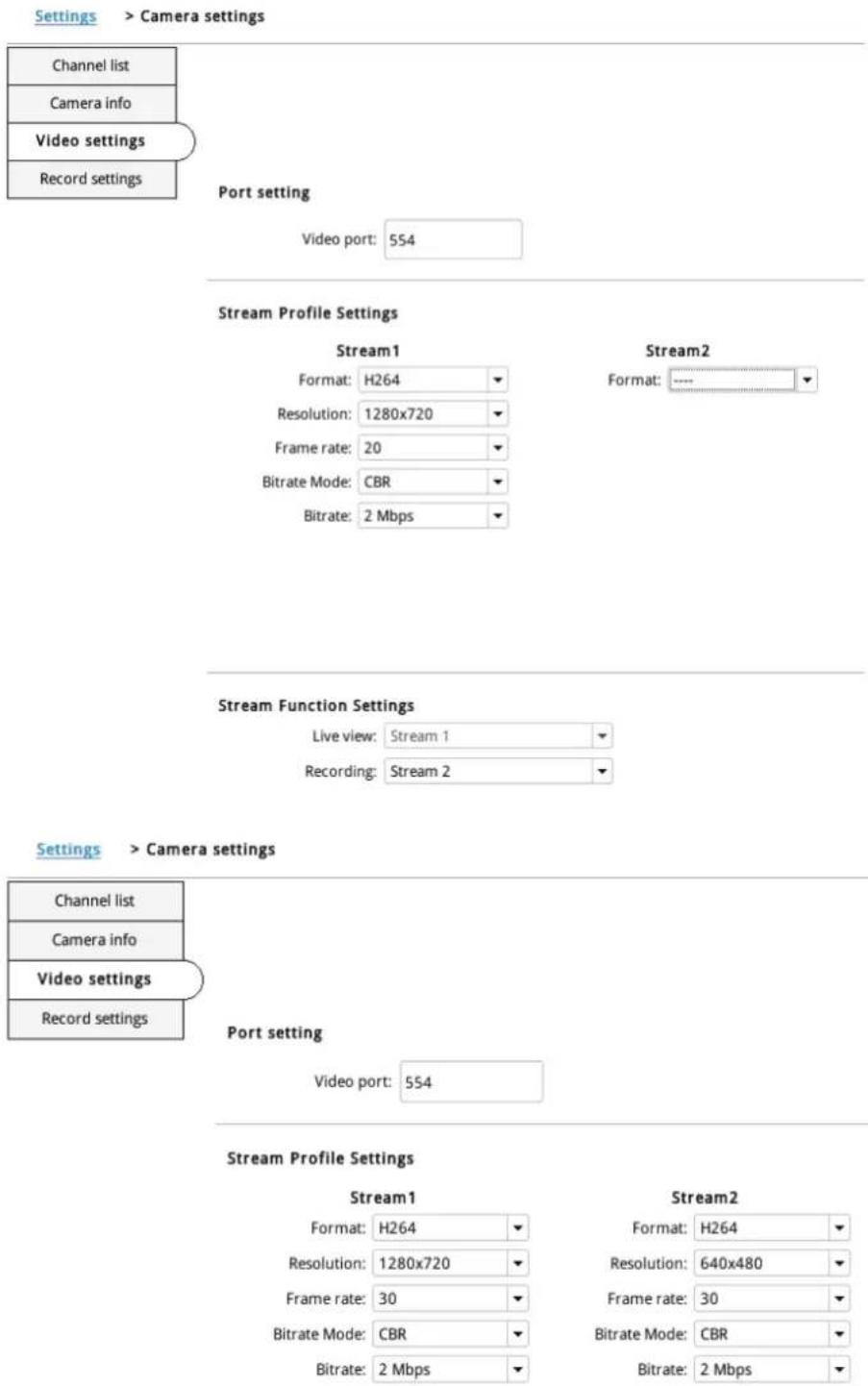
Then click "Apply" to finish adding the camera.

You will be able to use different video formats for continuous recording if it's a multi-stream capable camera.
Stream Function Settings

If "Enable dynamic streaming live view" is enabled, the NVR will select the best suitable resolution according to screen layout dynamically. Live stream profile will be taken over by this setting.
✗ Enable dynamic streaming live view
The "Dynamic streaming" status will be on if "Enable dynamic streaming live view" is enabled.

Add a camera manually

Camera settings
Auto search
Add manually
Channel
Channel name
Camera's IP address
Live stream
Record stream

Camera settings
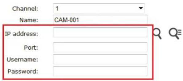

Channel 1

Preview
Simply follow the instruction described above but click "Add manually" function, enter the camera's IP address and credential in the "Camera Information" manually.
* Double-click on one from the list to continue.
Search again
| Brand | Model | IP address | Port | Installed |
| SONY | SNC-CH240 | 192.168.101.10 | 80 |
*If cameras are marked with "*" in the search result, it means those cameras are already configured and connected to the NVR.
Recording
The "recording" gives users the overall control of how and when a recording is performed and the quality of different types of recordings performed on each channel. It can help the recorder to operate with sufficient system resource by performing recording only when it's necessary with adjustable recording frame rate.
General
√ Enable HDD recycle (When enabled, it automatically starts when remaining HDD space reaches 20GB. Oldest data is recycled 32GB at a time.)
□ Always keep the previous □ days of recorded video
Channel specific
| Continuous | Schedule | Event * | Manual ** | Audio | |
| CH 1 | I Only | I Only | Full | Full |
*Event recording is always on
**Manual recording is turned on/off in live view
You can define the following in "General Settings":
- Enable cycle recording or not
- Recording frame rate
- Define to always keep a number of days of previously recorded data
- Enable/disable different recording types on different cameras
- Enable/disable audio recording

Always keep the previous

days of recorded video
Users can also set to keep a previous number of days of recording data by enabling the option below. This is quite often used in applications such as banking, where certain countries require always keeping a minimum previous number of days of recording data.
| Continuous | Schedule | Event * | Manual ** | Audio | |
| CH 1 | I Only | I Only | Full | Full |
Recording frame rate allows you to set different frame rates for different types of recording instead of recording at one frame rate only. Use the drop-down menu and select one of the pre-defined frame rates for a particular recording type.
There are two types of fps settings here: one is the fps that the NVR sets back to the camera, and this is the fps the NVR will be receiving from the camera. The other is recording fps, which will be limited by the live fps. (e.g., if the live fps is set to 10, choosing "Full" in the recording fps means it will only record at a maximum of 10fps.)
For MPEG/H.264, only i-frame or full (i+p frame) can be selected for recording fps.
| Continuous | Schedule | Event * | Manual ** | Audio | |
| CH 1 | I Only | I Only | Full | Full | √ |
You can also disable audio recording (record video only) for particular channels.
Scheduling
Schedule Recording Settings
Channel: Select a channel...
| Schedule Table | ||||||||||||||||||||||||||||
| 0 | 1 | 2 | 3 | 4 | 5 | 6 | 7 | 8 | 9 | 10 | 11 | 12 | 13 | 14 | 15 | 16 | 17 | 18 | 19 | 20 | 21 | 22 | 23 | |||||
| Sunday | ||||||||||||||||||||||||||||
| Monday | ||||||||||||||||||||||||||||
| Tuesday | ||||||||||||||||||||||||||||
| Wednesday | ||||||||||||||||||||||||||||
| Thursday | ||||||||||||||||||||||||||||
| Friday | ||||||||||||||||||||||||||||
| Saturday | ||||||||||||||||||||||||||||
Clear

Copy Schedule To Channel: Select a channel...
You can define the time range of the schedule recording for all channels on this page.
Channel: Select a channel...
Use the "Channel" drop-down menu and select a camera first.
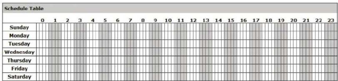
Clear
You can use the schedule table to set the time range. Click the cell boxes then move horizontally lets you set what hours to perform recording during a day. Click and move vertically lets you set what days to perform recording at a specific time.
* Each cell box represents 15 minutes of time. Click one or more boxes to omit consecutive recording.

You can also use the "Quick Configuration" to define recording time range instead of clicking cell boxes one by one on the timetable. Simply check what days you would like to perform recording and specify the recording duration by either choosing "All Day" or enter a start and end time for specific recording duration.
Copy Schedule To Channel: Select a channel...
Select the "Copy Schedule to Channel:" option if you would like to set the same recording schedule to another camera.
Preset Point Setting
PTZ Preset Settings
The recorder supports PTZ cameras and can set multiple preset points or retrieve and manage preset points that are set in the camera. This is helpful if you need to monitor multiple spots in one area from a particular camera.
Channel: Select a channel...

Focus:
Near
Far
Auto
* Click on the video to pan and tilt, use the scroll button for zoom control
Add
Preset points list
Sync from camera
Edit
To set up PTZ preset points:
- Select a camera from the "Channel" drop-down menu
- Use the PTZ control provided in the configuration page to set the preset point
- Press "Add" to add preset point
Press "Edit" to enter edit mode to change preset point names or delete preset points
The function of "Sync from camera" is to retrieve preset points from camera
You can choose to make this preset point a "Home" point among all other preset points, as well as making the camera to move to this particular point when an event is triggered.
* "Move Here when Event Trigger": In order for this function to work properly, please also complete configuration in "Event Configuration" >> "Event Trigger"
PTZ Preset Sequence
Channel: Select a channel...
Preset points


Sequence points and orders
Preview of the selected preset points

Dwell time:


Once you have multiple preset points defined for a camera, it is convenient for monitoring to set up the sequencing viewing among those preset points and let the recorder automatically switch between them for you.
To configure preset sequence for a camera,
- Select a channel from the "Channel" drop-down menu. The available preset points should be listed in "Camera Presets" section.
- Pick the ones you like for sequence viewing and press the "->" button to move them to the "Preset Sequence" section, then
- Use the up and down buttons to adjust their sequencing positions.
- Finally, select a dwell time from the drop-down menu and click "Apply" to save the configuration.
OSD Settings
Select a channel
Channel: Select a channel...
□ Display OSD
Display options
□ Display time □ Display FPS □ Display channel number □ Display customized text:

Preview

Preview - Click to see a preview of your OSD settings
Display position
| @ | ||
| Video | ||
The OSD (On Screen Display) allows users to add informational text messages and embed them onto the video. By default, this function is turned off. To add texts to one or more videos:
Select a channel
Channel: Select a channel...
□ Display OSD
Select a camera you would like to add text to and choose "Display OSD"
Display options
□ Display time □ Display FPS □ Display channel number □ Display customized text:

Choose one or more display options if you would also like the recorder to automatically embed the system time or the frame rate for you. Or simply choose to display a custom message of your own.
Display position
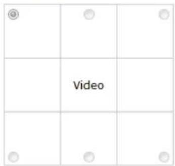
Next, define where the text will be displayed by either entering an X/Y value based on percentage or use the system pre-defined position from the drop-down menu.
Preview
Preview * Click to see a preview of your OSD settings
Click on the "Preview" button to see the preview of your setting and click "Apply" to save the configuration.
Event sources
The "Event sources" section allows users to define conditions that constitute an event, its corresponding trigger action and when it will be triggered. Such setting can reduce the management overhead and notify the administrator only when it's necessary.
Event sources
Device events
☐ Disk fail ☐ When HDD is recycling because of disk full ☐ When device starts up ☐ When device configuration changed ☐ When channel configuration changed ☐ When camera connection status changed ☐ When remaining HDD space is lower than GB (*minimum 2GB when HDD recycle is disabled) ☐ When the remaining space of event log file fails below 20% ☐ When event log file is recycling
Camera events
Reminder:
*Please make sure you have properly enabled and configured motion detection in the camera's web configuration UI before enabling motion detection in the device. The device only supports single region detection, and only the first region will be used even if you set multiple motion detection regions in the camera.
*Enable event log function to start event actions and keep event log file. If it is unchecked, the NVR only starts event recording when event is triggered.
| From camera | From CMS software | Enable event log | |||||
| Camera's digital inputs | Motion detection | ||||||
| Digital input | Port condition | ||||||
| CH 1 | Disable | ▼ | Disable | ▼ | □ | □ | ✕ |
Advance
The 1st step is to define the condition to trigger event, we can finish up the event triggers by setting:
- Which channels will have event trigger function enabled
•What is considered to be an event
Device events
□ Disk fail □ When HDD is recycling because of disk full □ When device starts up □ When device configuration changed ✗ When channel configuration changed ✗ When camera connection status changed ☐ When remaining HDD space is lower than ☐ GB (*minimum 2GB when HDD recycle is disabled) □ When the remaining space of event log file falls below 20% □ When event log file is recycling
Define which system events should trigger the recorder to send out notifications.
| From camera | From CMS software | Enable event log | |||||
| Camera's digital inputs | Motion detection | ||||||
| Digital input | Port condition | ||||||
| CH 1 | Disable | ▼ | Disable | ▼ | □ | □ | ✕ |
Use the checkbox to enable event trigger on the desired channels.
*Once motion detection is enabled in this page, please configure the motion area and enable motion detection in the corresponding channels (cameras) from camera's own web UI. The NVR only detects the first motion area set in the camera. The NVR recognizes the first motion area by its ID number set in the camera.
* Enabling the "From CMS software" option allows the NVR to receive events from the CMS software and start recording; events such as the intelligent video detection in the CMS.
You can setup the recorder to receive triggers from a particular camera's digital input.
- For cameras that come with physical digital input ports, their ports will be listed in the far left drop-down menu.
- Pick the desired channel, and then select the camera's input port from the drop-down menu.
- Select the trigger condition from the "Port condition" drop-down menu.
*The recorder only acts as a medium for pairing up input/output ports between cameras and the recorder.
*Only connected cameras will be displayed in the list.
*Some cameras only allow one trigger source be configured at a time, e.g.: if the camera has the motion detection function turned on, its digital input will be disabled and vice versa. Under such circumstance, if you set to use camera's digital input port as the event trigger source, you will not be able to select motion detection as the trigger source for this camera

Click "Advance" button to set up event schedule.
The "recording buffer" allows user to define "pre-alarm" and "post-alarm" time for event recordings. The "pre-alarm" time sets the NVR to record in advance when an event is triggered. The "post-alarm" time sets the NVR to continue recording for a period of time after an event trigger is finished.
Notifications
Event servers are to be used with event trigger actions. In case of unusual motion detected by the camera or a disk failure, the recorder can send notification with the acceptable format (image/txt) to a destined event server according to the configuration.
E-Mail notification
Primary SMTP server
Network address: (* Enter domain name or IP address)
Port: 25
Authentication:
Username:
Password:
Add backup SMTP server
Send mail setting

- Enter the hostname or the IP address of the SMTP server
- Enter the port of the SMTP server
- Specify the sender's name in the "Sender's name" field
- Enter the sender's e-mail address
- Check "Enable Authentication" and enter the username and password of the SMTP server if it requires authentication.
- Click "Apply" to save the configuration.
- The NVR supports SMTP servers that use base64 or MD5 authentication methods.
- 3rd party free E-mail services such as Gmail (openssl) is supported.
FTP notification
Server settings:
Server name:
Network address:
(* Enter domain name or IP address)
Port: 21

Allow anonymous login:
Username:
Password:

Use passive mode:
Test connection:
Test
FTP server list:
Add
Remove
Server name
*Click on one to edit its settings
Upload settings:
Upload path:
To add an FTP server,
- Start by giving a name to the server that you are adding to the recorder
- Enter the hostname or the IP address of the FTP server
- Enter the communication port of the FTP server (usually port 21)
- Enter the username and password of the FTP server if it's required
- Check "Use Passive Mode" if it's required or leaves it unchecked to use active mode
- Click "Test" to verify if all information is entered correctly and the connection to the FTP server can be established successfully
- Click "Add" for the settings to take effect
Event actions
√ Warning sound
E-mail pre-defined text file
☐ Upload pre-defined text file to FTP servers
E-mail video snapshot
☐ Upload video snapshot to FTP servers
E-mail or upload 1 ▼ frames per event
Define how the notifications will be sent and where they will be sent.
- Event trigger may not work for cameras that are placed outside of your local network or on the Internet until the "UPnP Port Forwarding" is enabled in both the NVR and the router.
E-Map
Local E-Map Setting

E-Map monitor is a function that alerts users whenever there is an event triggered (e.g. motion detected) from a camera with a geographical perspective. With this function, users can quickly identify which camera has detected an unusual event and where this event is happening. This function works by incorporating the event detection function as well as the recording function, which, as a result, helps users take all the necessary actions when an unusual event occurs.
Change E-Map image: Browse... Upload (*Size limit: 500KB)
To replace the map, click "Browse" button to locate the new map image file from the local PC and then click "Upload".
* Only JPG, PNG, and GIF file formats are supported with file size under 500KB.
Channel list

Add all channels: display all camera icons on E-map Reset E-Map: remove all camera icons on E-map Click CH ID to display camera icon of this camera on E-map
![graph TD A["Room 501"] --> B["Room 502"] B --> C["Room 211"] C --> D["Room 216"] D --> E["Room 215"] E --> F["Room 213"] F --> G["Room 214"] G --> H["Room 211"] H --> I["Room 210"] I --> J["Room 209"] J --> K["Room 208"] K --> L["Room 207"] L --> M["Room 206"] M --> N["Room 205"] N --> O["Room 204"]…](/content/2026/05/805090/images/f77578ce9c0ff62e2167dfbd776c697b1d08af41c5d6298401f0a97da2266e7e.jpg)
Then click and drag the camera icon to move the camera to define its location.
Access the E-Map by enabling "Event view".
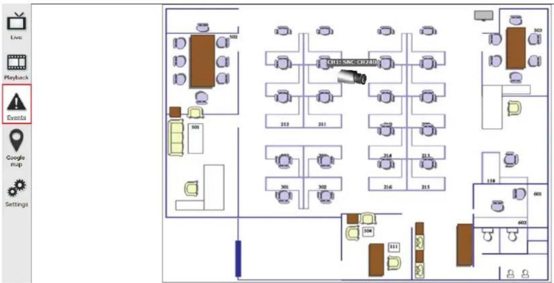
You can click on the camera icon to display video.

Google Map Setting

The Google Map monitor is a similar function to the aforementioned E-Map monitor. It is useful if you are managing multiple cameras from different locations.
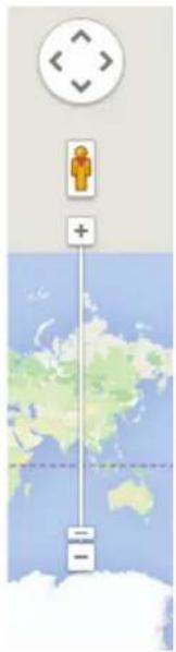
To configure locations of each camera, first determine the location you'd like to place the camera to on the map. You can do so by:
- Zoom in to a smaller area by using the zoom control bar on the map
- Zoom in to a smaller area by using the mouse scroll button
You can also go to a specific place on the map by entering its address or the name of the place in the "Address or places of interest" field
Once the location has been determined, click and drag the camera icon to move it to the desired location
* The Google Map Monitor requires active Internet connection and can not be used in conjunction with the regular E-Map monitor function.
Device Info
General information
Device name:
Model name: NVR16
Firmware version: v1.5.0.70990
Device up since: 2014/06/03 09:05:56
Network information
Connection type: Auto mode: ON Static IP
Device IP: 192.168.101.50
HTTP port: 80
Streaming port: 9877
MAC address: 00:22:4E:E1:00:CA
DHCP server: ON
UPnP port forwarding: OFF
Device info gives users a glance of the overall system status
and allows users to perform maintenance tasks such as upgrading firmware, restore/backup device settings or reboot device, etc.
NVR Setup
System Configuration Channel Configuration Event Configuration Recording Configuration System Options Device Information System Logs Maintenance Disk Status USB Backup
General Information
Device Name:
Model Name: SVR-632
Firmware Version: 1.0.0.39090
Device Time: July 18, 2011 17:51:10
Network Information
Network Type: DHCP
Device IP: 192.168.102.48
HTTP Port: 80
Streaming Port: 9877
MAC Address: 00:19:0f:07:39:5a
UPnP Port Forwarding: Disabled
The "Device Information" provides the general information of the device such as firmware version and system time. It also provides information of the current network settings and status.
Log
| ID | Time | Type | Sub-type | CH | AP | IP | User |
| 1 | 2014/06/03 15:51:58 | User | User login | Web Event Receiver | 192.168.101.60 | admin | |
| 2 | 2014/06/03 15:51:56 | User | User logout | Web Event Receiver | 192.168.101.60 | admin | |
| 3 | 2014/06/03 15:50:08 | User | User login | Web Event Receiver | 192.168.101.60 | admin | |
| 4 | 2014/06/03 15:50:07 | User | User logout | Web Event Receiver | 192.168.101.60 | admin | |
| 5 | 2014/06/03 15:45:02 | User | User login | Web Event Receiver | 192.168.101.60 | admin | |
| 6 | 2014/06/03 15:45:00 | User | User logout | Web Event Receiver | 192.168.101.60 | admin | |
| 7 | 2014/06/03 15:22:33 | User | User login | Web Event Receiver | 192.168.101.60 | admin | |
| 8 | 2014/06/03 15:22:31 | User | User logout | Web Event Receiver | 192.168.101.60 | admin | |
| 9 | 2014/06/03 15:21:20 | User | User login | Web Event Receiver | 192.168.101.60 | admin | |
| 10 | 2014/06/03 15:21:18 | User | User logout | Web Event Receiver | 192.168.101.60 | admin | |
| 11 | 2014/06/03 15:21:16 | User | User login | Web Event Receiver | 192.168.101.60 | admin | |
| 12 | 2014/06/03 15:21:13 | User | User login | Web | 192.168.101.60 | admin | |
| 13 | 2014/06/03 15:03:21 | User | User logout | Web Event Receiver | 192.168.101.60 | admin | |
| 14 | 2014/06/03 13:57:30 | User | User login | Web Event Receiver | 192.168.101.60 | admin | |
| 15 | 2014/06/03 13:57:28 | User | User logout | Web Event Receiver | 192.168.101.60 | admin | |
| 16 | 2014/06/03 13:57:16 | User | User login | Web Event Receiver | 192.168.101.60 | admin | |
| 17 | 2014/06/03 13:57:13 | User | User login | Web | 192.168.101.60 | admin | |
| 18 | 2014/06/03 10:17:25 | User | User logout | Web Event Receiver | 192.168.101.60 | admin | |
| 19 | 2014/06/03 10:12:08 | User | User login | Web Event Receiver | 192.168.101.60 | admin | |
| 20 | 2014/06/03 10:12:06 | User | User logout | Web Event Receiver | 192.168.101.60 | admin | |
| 21 | 2014/06/03 10:03:19 | User | User login | Web Event Receiver | 192.168.101.60 | admin | |
| 22 | 2014/06/03 10:03:17 | User | User logout | Web Event Receiver | 192.168.101.60 | admin | |
| 23 | 2014/06/03 10:03:08 | User | User login | Web Event Receiver | 192.168.101.60 | admin | |
| 24 | 2014/06/03 10:03:06 | User | User logout | Web Event Receiver | 192.168.101.60 | admin | |
| 25 | 2014/06/03 10:02:58 | User | User login | Web Event Receiver | 192.168.101.60 | admin | |
| 26 | 2014/06/03 10:02:56 | User | User logout | Web Event Receiver | 192.168.101.60 | admin | |
| 27 | 2014/06/03 09:50:30 | User | User login | Web Event Receiver | 192.168.101.60 | admin | |
| 28 | 2014/06/03 09:50:29 | User | User logout | Web Event Receiver | 192.168.101.60 | admin | |
| 29 | 2014/06/03 09:38:33 | User | User login | Web Event Receiver | 192.168.101.60 | admin | |
| 30 | 2014/06/03 09:38:31 | User | User logout | Web Event Receiver | 192.168.101.60 | admin |
"Log" keeps a record of what's been happening to the device and provides basic information for troubleshooting.
Maintenance

Maintenance
Settings > Maintenance
Upgrade firmware
Upgrade Current version: v1.0.1.79272
Restart device
Restart
Restart camera
Select a channel... ▼ Restart
Reset to factory default
Reset to default
Change logo
"Maintenance" provides functions for users to:
• Perform Firmware Upgrade (Only on Web UI) - Restart the NVR when necessary - Restart cameras directly from the NVR - Reset the NVR's settings to their factory default values - Change logo of NVR - Enable auto reboot: NVR will reboot automatically when system is abnormal.
Firmware Upgrade
The firmware can be upgraded through web UI. Before upgrading firmware, please backup configuration in advance.
** The firmware file comes with a ".bin" file extension.

Click "Browse...", A new dialog should display and let you choose the location of the firmware file.
Upgrade firmware
Locate firmware: C:\Gordon\tmp\NoBrand_S Browse... Upgrade Current version: v1.5.0.70990
When done, click "Upgrade".
Follow the on screen instruction and wait for the process to finish (After upgrade, the system will reboot automatically, it's part of the process)
Backup & Restore
Backup configuration
Backup
Restore configuration
Locate configuration file:
Browse...
Restore
This function allows users to back up the NVR's settings to a local hard drive.
Users can also restore the NVR's settings from a previously saved configuration file.
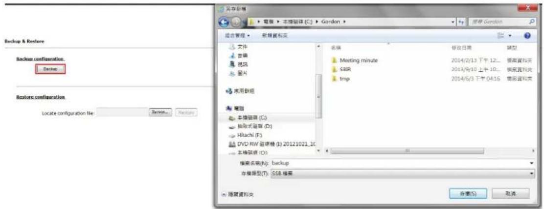
On the Web UI, the configuration can be backed up to or restored from a local computer.
Click "Backup" to store the configuration file on the local computer.
On the local UI, the configuration can be backed up to or restored from a USB disk. It is required to plug in a USB disk formatted in FAT32 prior to using the backup and restore functions.
Once it's detected, click "Backup" to store the configuration file on the USB disk.

USB backup
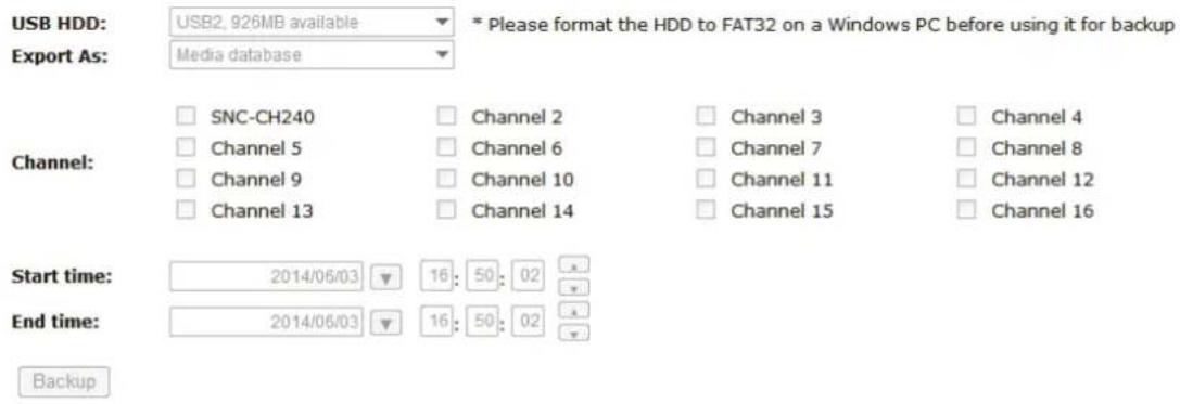
This function allows users to back up the recording data in its database file format as well as in AVI to an externally connected USB hard disk.
USB HDD: USB2, 926MB available
The USB hard disk(s) will be listed in the drop-down menu displaying the remaining disk space. Make your selection from the drop-down menu if you have more than one disk connected to the NVR.

Next, select the channels from which you would like to back up the recording data. Maximum 4 channels can be selected at once.

Configure the start and end time of the recording data you would like to back up and click the "Backup" button to begin.
Things to pay attention to regarding the USB Backup function
Limitation:
- It does not support USB Hub to extend the number of HDDs connected to the NVR.
- Only one backup process can be performed at a time. Maximum 4 channels can be selected for backup.
- Only FAT32 USB hard disks are supported for backup.
- The USB hard disk needs to have more than 100MB of remaining space.
- If multiple partitions are present on one disk, only the first partition will be detected and used for backup.
Process:
- Progress will be displayed on the UI.
- If the backup process gets interrupted, and the process stops at a point in time before the "END Time" user defined, such time will be displayed on the UI.
- A folder will be automatically created on the USB hard disk with a name format like 0028687831_20100610151515_20100605110010_20100606110010 (MAC_backupbuttonclicktime_starttime_endtime).
Note:
- Please plug in the USB HDD only after the NVR is fully started, or the HDDs will be incorrectly mounted.
- Play the backed up files using the NVR media player.
NVR Media Player
You can use the NVR Media Player to play the exported AVI files or media database file. This can save you the trouble of installing third-party media player or codecs when playing the exported AVI videos.
The NVR Media Player will be automatically installed after the CMS software is installed. You can find it in the Windows Start menu.
Play the backup file with the NVR Media Player
Play Media database
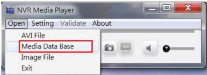
The backup files can be played with the NVR media player. To do so, open the player and select "Open" >> "Media Database"

Click "Browse..." to select the file from the USB disk.

A new dialog should be prompted for you to select the file location.
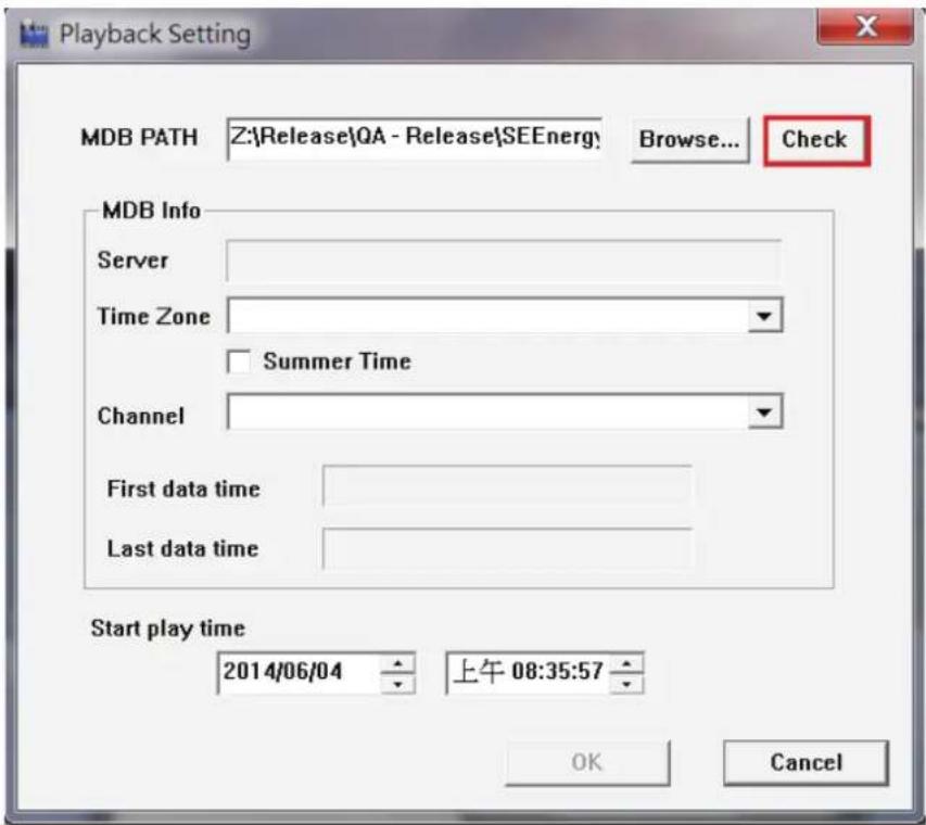
When done, click "Check" to validate the file.
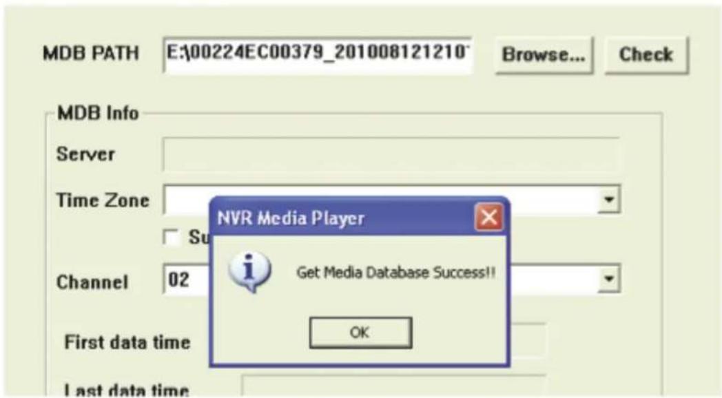
Once the file has been successfully verified, you should be prompted with the message shown below.
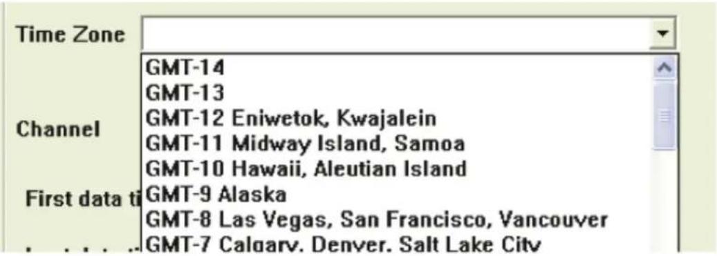
Select the time zone according to your current location.

Finally, click "OK" to begin playing. The player should now play the backed up file.
Play Media database
Open the player and select "Open" >> "AVI File"


Click "Open" to play file
Open Event Snapshot images with NVR Media Player
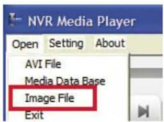
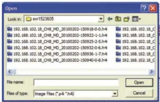
The NVR sends snapshots that are taken when an event occurs to a destined FTP server or mail recipient. These types of snapshot images are saved in a proprietary image file format, h4i or p4i, and can only be opened by the NVR media player.
Note: In case of incorrect installation and improper use in a residential area, interference to radio devices and other electronic devices could be caused.
It is recommended to use the device where applicable with shielded cables (also shielded with networking products of cable Category 5e and higher). The device was tested to comply with the limits for Computer and IT accessories of Class A according to the requirements of EN 55022.
Warning: This product complies with the test class A - It may be used in the living area but could cause radio interference; in this case, it may be demanded by the operator to take appropriate corrective action at his/her own expense.
Declaration of Conformity:
The device meets the EMC requirements according to EN 55022 class A and EN 55024 for ITE category with external or built-in power supply to meet the requirements of EN 61000-3-2 and EN 61000-3-3 according to the EMC Directive 2004/108/EC. The declaration of Conformity can be requested by post at the following manufacturer address.
www.assmann.com
ASSMANN Electronic GmbH
Auf dem Schüffel 3
58513 Lüdenscheid
Germany




- DIGITUS® PROFESSIONAL
- NETWORK VIDEO RECORDER 1080P RESOLUTION 10/100/1000 MBPS
- TABLE OF CONTENTS
- HARDWARE 4
- CONNECT TO THE NVR 4
- MAIN/LIVE VIEW 12
- PLAYBACK VIEW 20
- EVENT VIEW.... 26
- NVR SETUP - SETTINGS 28
- HARDWARE
- CONNECT TO THE NVR
- USE NVR SEARCH UTILITY
- ACCESS THE NVR WITH ITS DEFAULT IP ADDRESS
- 1
- 2
- MAIN/LIVE VIEW
- THE UI'S 5 MAIN FUNCTIONS
- DATE AND TIME DISPLAY
- USER'S CONFIGURATION
- HARDWARE EVENTS NOTIFICATION
- CHANNELS STATUS
- VIDEO FRAME
- LIST VIEW
- 1, 4, 9, 16 PATTERN VIEW
- SEQUENCE VIEW
- SAVE VIEW
- SAVED VIEW
- HIDDEN ACCORDION MENU
- PLAYBACK VIEW
- ZOOM ON A RANGE OF TIME
- MINIMIZE THE BAR OF THE PLAYBACK
- CERTAIN FUNCTIONS YOU CAN PERFORM ON THE PLAYBACK VIDEO
- TAKE A SNAPSHOT OF A PLAYBACK VIDEO
- EVENT VIEW
- NVR SETUP - SETTINGS
- DISPLAY
- NETWORK SETTINGS
- SET NETWORK AUTOMATICALLY
- GET NETWORK CONFIGURATION AUTOMATICALLY
- THIS SETS THE NVR AS A DHCP CLIENT
- USE MANUAL CONFIGURATION
- SET THE NVR TO USE A STATIC IP
- SETTINGS > NETWORK SETTINGS
- DHCP SERVER
- DDNS SERVICE
- TIME AND DATE
- TIME CONFIGURATION
- STORAGE
- DISK ACTIONS
- USERS & PRIVILEGES
- ADD A NEW USER
- CHANGE THE PASSWORD OF THE "ADMIN" ACCOUNT
- GROUP PRIVILEGE
- GROUP PRIVILEGES
- CAMERA
- AUTOMATIC SEARCH
- STREAM FUNCTION SETTINGS
- ADD A CAMERA MANUALLY
- RECORDING
- GENERAL
- SCHEDULING
- SCHEDULE RECORDING SETTINGS
- PRESET POINT SETTING
- PTZ PRESET SETTINGS
- PTZ PRESET SEQUENCE
- OSD SETTINGS
- SELECT A CHANNEL
- DISPLAY OPTIONS
- PREVIEW
- DISPLAY POSITION
- EVENT SOURCES
- DEVICE EVENTS
- CAMERA EVENTS
- REMINDER
- NOTIFICATIONS
- PRIMARY SMTP SERVER
- SEND MAIL SETTING
- SERVER SETTINGS
- FTP SERVER LIST
- UPLOAD SETTINGS
- EVENT ACTIONS
- E-MAP
- LOCAL E-MAP SETTING
- CHANNEL LIST
- GOOGLE MAP SETTING
- DEVICE INFO
- GENERAL INFORMATION
- NETWORK INFORMATION
- NVR SETUP
- LOG
- MAINTENANCE
- FIRMWARE UPGRADE
- UPGRADE FIRMWARE
- BACKUP & RESTORE
- USB BACKUP
- THINGS TO PAY ATTENTION TO REGARDING THE USB BACKUP FUNCTION
- LIMITATION
- PROCESS
- NOTE
- NVR MEDIA PLAYER
- PLAY THE BACKUP FILE WITH THE NVR MEDIA PLAYER
- PLAY MEDIA DATABASE
- OPEN EVENT SNAPSHOT IMAGES WITH NVR MEDIA PLAYER
Brand : Digitus
Model : DN-16112
Category : VCR