
PLC-XU116 - Vidéo-projecteur SANYO - Free user manual and instructions
Find the device manual for free PLC-XU116 SANYO in PDF.


| Product Type | Video Projector |
| Model | PLC-XU116 |
| Brand | Sanyo |
| Dimensions (W x H x D) | Approx. 310 x 89 x 230 mm |
| Weight | Approx. 3.0 kg |
| Power Consumption | 290 W (max) |
| Light Source | UHP lamp, 200 W |
| Display Technology | DLP |
| Resolution | XGA (1024 x 768) |
| Brightness | 3500 lumens |
| Contrast Ratio | 2000:1 |
| Projection Lens | 1.2x manual zoom |
| Input Terminals | HDMI, VGA, S-Video, Composite, Audio |
| Output Terminals | VGA out, Audio out |
| Features | Keystone correction, Auto setup, Remote control |
| Maintenance | Clean air filter every 100 hours |
| Safety | Auto power-off, Overheat protection |
| Spare Parts | Replacement lamp available |
| Repairability | User-replaceable lamp and filter |
Frequently Asked Questions - PLC-XU116 SANYO
User questions about PLC-XU116 SANYO
0 question about this device. Answer the ones you know or ask your own.
Ask a new question about this device
Download the instructions for your Vidéo-projecteur in PDF format for free! Find your manual PLC-XU116 - SANYO and take your electronic device back in hand. On this page are published all the documents necessary for the use of your device. PLC-XU116 by SANYO.
USER MANUAL PLC-XU116 SANYO
Multimedia Projector MODEL PLC-XU116
Network Supported
□ Wireless LAN
IEEE802.11b/g/n
□ Wired LAN
* Refer to the owner's manuals below for details about network and memory viewer function.
■ Network Set-up and Operation
■ Memory viewer function

natural_image
Line drawing of a projector device with ventilation grilles and control panel (no text or symbols)Owner's Manual
PJLink™
This Multimedia Projector is designed with the most advanced technology for portability, durability, and ease of use. This projector utilizes built-in multimedia features, a palette of 16.77 million colors, and matrix liquid crystal display (LCD) technology.
◆ Compact Design
This projector is designed compact in size and weight. It is easy to carry and installed anywhere you wish to use.
♦ Capable of 360-degree Projection
This projector is capable of 360-degree projection. *Some restriction required, see page 7.
◆ Simple Computer System Setting
The projector has the Multi-scan system to conform to almost all computer output signals quickly (p.33). Up to WUXGA resolution can be accepted.
Power Management
The Power management function reduces power consumption and maintains the lamp life (p.55).
◆ Quick Termination
The AC power cord can be unplugged immediately after turning off the projector without waiting for the termination of the cooling fan rotation (p.23).
♦ Logo Function
The Logo function allows you to customize the screen logo (pp.51-53). You can capture an image for the screen logo and use it for the starting-up display or between presentations.
♦ Multilanguage Menu Display
Operation menu is available in 17 languages; English, German, French, Italian, Spanish, Portuguese, Dutch, Swedish, Finnish, Polish, Hungarian, Romanian, Russian, Chinese, Korean, Japanese and Thai (p.48).
◆ Security Function
The Security function helps you to ensure security of the projector. With the Key lock function, you can lock the operation on the top control or the remote control (p.58). PIN code lock function prevents unauthorized use of the projector (pp.22, 58-59).
◆ Helpful Maintenance Functions
Lamp and filter maintenance functions provide for better and proper maintenance of the projector.
♦ LAN Network Function
This projector is loaded with the Wired and Wireless LAN network functions.
√ Note:
- The On-Screen Menu and figures in this manual may differ slightly from the product.
-
The contents of this manual are subject to change without notice.
-
You can project an image on a computer as well as operate and manage the projector via network.
- The projector provides the "USB display" function that the image and sound are sent to the projector by connecting the computer to the projector with a USB cable.
- This projector is capable of the wireless LAN simple setting function by attaching the supplied USB memory to a computer.
For details, refer to the owner's manual of "Network Set-up and Operation."
♦ Memory Viewer Function
Insert the dedicated USB memory into the projector to project images or movie files stored within. You do not have to carry computers or other equipment for a presentation.
For details, refer to the owner's manual of "Memory viewer function".
♦ Auto setup Function
This function enables Input search, Auto Keystone correction and Auto PC adjustment by simple pressing the AUTO SETUP button (pp. 26,49).
♦ Colorboard Function
At the time of simple projection on the colored wall, you can get the close color image to the color image projected on a white screen by selecting the similar color to the wall color from the preset four colors.
◆ Closed Caption
This is a printed version of the program sound or other information displayed on the screen. You can turn on the feature and switch the channels (p.56).
Corner Correction
With the "Horizontal and vertical keystone correction function" and "Corner keystone correction function" of this projector, you can correct the keystone distortion even when projecting from the diagonal to the screen (pp.27, 50).
Features and Design 2
Table of Contents 3
To the Owner....4
Safety Instructions .... 5
Air Circulation 6
Moving the Projector 6
Installing the Projector in Proper Directions 7
Compliance 8
Part Names and Functions ..... 9
Front 9
Back 9
Bottom 9
Rear Terminal 10
Top Control 11
Remote Control 12
Remote Control Battery Installation 13
Remote Control Operating Range 13
Remote Control Code 13
Laser Pointer Function 14
Pointer Function 14
Wireless Mouse Operation 15
Adjustable Feet 15
Installation.... 16
Positioning the Projector 16
Connecting to a Computer 17
Connecting to Video Equipment 18
Connecting to Component Video Equipment 19
Connecting the AC Power Cord 20
Basic Operation 21
Turning On the Projector 21
Turning Off the Projector 23
How to Operate the On-Screen Menu 24
Menu Bar 25
Zoom and Focus Adjustment 26
Auto Setup Function 26
Keystone Correction 27
Sound Adjustment 28
Remote Control Operation 29
Computer Input 31
Input Source Selection (RGB: Computer 1/
Computer 2(Analog) 31
Input Source Selection (RGB(PC digital), RGB(AV HDCP)) 32
Computer System Selection 33
Auto PC adjustment 34
Manual PC adjustment 35
Image Mode Selection 37
Image Adjustment 38
Screen Size Adjustment 39
Video Input 41
Input Source Selection (Video, S-video) 41
Input Source Selection (Component, RGB Scart 21-pin) 42
Video System Selection 43
Image Mode Selection 44
Image Adjustment 45
Screen Size Adjustment 47
Setting 48
Setting 48
Information 62
Input Source Information Display 62
Maintenance and Cleaning 63
WARNING indicator 63
Cleaning the Filters 64
Resetting the Filter Counter 64
Attaching the Lens Cap 65
Cleaning the Projection Lens 65
Cleaning the Projector Cabinet 65
Lamp Replacement 66
Resetting the Lamp Counter 67
Appendix 68
Troubleshooting 68
Menu Tree 72
Indicators and Projector Condition 74
Compatible Computer Specifications 75
Technical Specifications 77
Optional Parts 78
PJ Link Notice 79
Configurations of Terminals 80
PIN Code Number Memo 81
USB Thumb Drive Case 81
Dimensions 82
Trademarks
Each name of corporations or products in this book is either a registered trademark or a trademark of its respective corporation.
Before installing and operating this projector, read this manual thoroughly.
This projector provides many convenient features and functions. Operating the projector properly enables you to manage those features and maintains it in good condition for many years to come.
Improper operation may result in not only shortening the product-life, but also malfunctions, fire hazard, or other accidents.
If your projector seems to operate improperly, read this manual again, check operations and cable connections and try the solutions in the “Troubleshooting” section on pages 68-70 of this manual. If the problem still persists, contact the dealer where you purchased the projector or the service center.
 | CAUTIONRISK OF ELECTRIC SHOCKDO NOT OPEN | |
| CAUTION: TO REDUCE THE RISK OF ELECTRICSHOCK, DO NOT REMOVE COVER (ORBACK). NO USER-SERVICEABLE PARTSINSIDE EXCEPT LAMP REPLACEMENT.REFER SERVICING TO QUALIFIEDSERVICE PERSONNEL. | ||
 | THIS SYMBOL INDICATES THAT DANGEROUSVOLTAGE CONSTITUTING A RISK OF ELECTRICSHOCK IS PRESENT WITHIN THIS UNIT. | |
 | THIS SYMBOL INDICATES THAT THERE AREIMPORTANT OPERATING AND MAINTENANCEINSTRUCTIONS IN THE OWNER'S MANUALWITH THIS UNIT. | |
FOR EU USERS
The symbol mark and recycling systems described below apply to EU countries and do not apply to countries in other areas of the world.
Your product is designed and manufactured with high quality materials and components which can be recycled and/or reused.
The symbol mark means that electrical and electronic equipment, batteries and accumulators, at their end-of-life, should be disposed of separately from your household waste. Note:
If a chemical symbol is printed beneath the symbol mark, this chemical symbol means that the battery or accumulator contains a heavy metal at a certain concentration. This will be indicated as follows: Hg: mercury, Cd: cadmium, Pb: lead In the European Union there are separate collection systems for used electrical and electronic equipment, batteries and accumulators.
Please, dispose of them correctly at your local community waste collection/recycling centre.
Please, help us to conserve the environment we live in!

READ AND KEEP THIS OWNER'S MANUAL FOR LATER USE.

Safety Precaution
• THIS APPARATUS MUST BE EARTHED.
• TO REDUCE THE RISK OF FIRE OR ELECTRIC SHOCK, DO NOT EXPOSE THIS APPLIANCE TO RAIN OR MOISTURE.
This projector produces intense light from the projection lens. Do not stare directly into the lens, otherwise eye damage could result. Be especially careful that children do not stare directly into the beam.
- Install the projector in a proper position. Otherwise it may result in fire hazard.
- Allowing the proper amount of space on the top, sides, and rear of the projector cabinet is critical for proper air circulation and cooling of the unit. The dimension shown here indicate the minimum space required. If the projector is to be built into a compartment of similarly enclosed, these minimum distances must be maintained.
- Do not cover the ventilation slot on the projector. Heat build-up can reduce the service life of your projector, and can also be dangerous.
SIDE and TOP REAR

- If the projector is unused for an extended time, unplug the projector from the power outlet.
-Do not project the same image for a long time. The afterimage may remain on the LCD panels by the characteristic of panel.

CAUTION
DO NOT SET THE PROJECTOR IN GREASY, WET, OR SMOKY CONDITIONS SUCH AS IN A KITCHEN TO PREVENT A BREAKDOWN OR A DISASTER. IF THE PROJECTOR COMES IN CONTACT WITH OIL OR CHEMICALS, IT MAY BECOME DETERIORATED.

CAUTION
Not for use in a computer room as defined in the Standard for the Protection of Electronic Computer/Data Processing Equipment, ANSI/NFPA 75.
All the safety and operating instructions should be read before the product is operated.
Read all of the instructions given here and retain them for later use. Unplug this projector from AC power supply before cleaning. Do not use liquid or aerosol cleaners. Use a damp cloth for cleaning.
Follow all warnings and instructions marked on the projector.
For added protection to the projector during a lightning storm, or when it is left unattended and unused periods of time, unplug it from the wall outlet. This will prevent damage due to lightning and power line surges.
Do not expose this unit to rain or use near water... for example, in a wet basement, near a swimming pool, etc...
Do not use attachments not recommended by manufacturer as they may cause hazards.
Do not place this projector on an unstable cart, sta or table. The projector may fall, causing serious injury to a child or adult, and serious damage to the Use only with a cart or stand recommended by the manufacturer, or sold with the projector. Wall or shelf mounting should follow the manufacturer's instructions, and should use a mounting kit approved by the manufacturers.
An appliance and cart combination should be moved with care. Qu stops, excessive force, and uneven surfaces may cause the appliance and cart combination to overturn.

Slots and openings in the back and bottom of the cabinet are provided for ventilation, to ensure reliable operation of the equipment and to protect it from overheating.
The openings should never be covered with cloth or other materials, and the bottom opening should not be blocked by placing the projector on a bed, sofa, rug, or other similar surface. This projector should never be placed near or over a radiator or heat register.
This projector should not be placed in a built-in installation such as a book case unless proper ventilation is provided.
Never push objects of any kind into this projector through cabinet slots as they may touch dangerous voltage points or short out parts that could result in a fire or electric shock. Never spill liquid of any kind on the projector.
Do not install the projector near the ventilation duct of air-conditioning equipment.
This projector should be operated only from the type of power source indicated on the marking label. If you are not sure of the type of power supplied, consult your authorized dealer or local power company.
Do not overload wall outlets and extension cords as this can result in fire or electric shock. Do not allow anything to rest on the power cord. Do not locate this projector where the cord may be damaged by persons walking on fort. long
Do not attempt to service this projector yourself as opening or removing Covers may expose you to dangerous voltage or other hazards. Refer all servicing to qualified service personnel.
Unplug this projector from wall outlet and refer servicing the qualified service personnel under the following conditions:
a. When the power cord or plug is damaged or frayed.
,b. If liquid has been spilled into the projector.
c. If the projector has been exposed to rain or water.
project the projector does not operate normally by following the operating instructions. Adjust only those controls that are covered by the operating instructions as improper adjustment of other controls may result in damage and will often require extensive work by a qualified technician to restore the projector to normal operation.
e. If the projector has been dropped or the cabinet has been damaged.
f. When the projector exhibits a distinct change in performance-this indicates a need for service.
When replacement parts are required, be sure the service technician has used replacement parts specified by the manufacturer that have the same characteristics as the original part. Unauthorized substitutions may result in fire, electric shock, or injury to persons.
Upon completion of any service or repairs to this projector, ask the service technician to perform routine safety checks to determine that the projector is in safe operating condition.
NOTE FOR CUSTOMERS IN THE US Hg LAMP(S) INSIDE THIS PRODUCT CONTAIN MERCURY AND MUST BE RECYCLED OR DISPOSED OF ACCORDING TO LOCAL, STATE OR FEDERAL LAWS.
Air Circulation
Openings in the cabinet are provided for ventilation. To ensure reliable operation of the product and to protect it from overheating, these openings must not be blocked or covered.

CAUTION
Hot air is exhausted from the exhaust vent. When using or installing the projector, the following precautions should be taken.
- Do not put any flammable object or spray can near the projector, hot air is exhausted from the air vents.
- Keep the exhaust vent at least 3' (1m) away from any objects.
- Do not touch a peripheral part of the exhaust especially screws and metallic parts. These areas will become hot while the projector is being used.
- Do not put anything on the cabinet. Objects put on the cabinet will not only get damaged but also may cause fire hazard by heat.
Cooling fans are provided to cool down the projector. The fans' running speed is changed according to the temperature inside the projector.


Moving the Projector
When moving the projector, replace the Lens Cap and retract adjustable feet to prevent damage to the lens and cabinet.
When the projector is not in use for an extended period, put it into the supplied carrying case with the lens side up.

CAUTION
The carrying case (supplied) is intended for protection against dust and scratches on surface of the cabinet, and it is not designed to protect an appliance from external forces. Do not transport the projector by courier or any other transport service with this case, otherwise the projector can be damaged. When handling the projector, do not drop, bump, subject it to strong forces, or put other things on the cabinet.

CAUTION IN CARRYING OR TRANSPORTING THE PROJECTOR
Do not drop or bump the projector, otherwise damages or malfunctions may result.
- When carrying the projector, use a suitable carrying case.
- Do not transport the projector by courier or any other transport service in an unsuitable transport case. This may cause damage to the projector. For information about transporting the projector by courier or any other transport service, consult your dealer.
- Do not put the projector in a case before the projector is cooled enough.
Installing the Projector in Proper Directions
Use the projector properly in specified positions. Improper positioning may reduce the lamp life and result in severe accident or fire hazard.
This projector can project the picture upward, downward or backward, perpendicular to the plane of the screen as shown in the figure below.


Be sure to set the Lamp control in High and the Fan control in On 3 in the setting menu when using the projector inclined at between +40 degrees to +140 degrees to the horizontal plane at altitudes between 0 and approximately 1,600 meters above sea level.
Be sure to set the Fan control in On 2 when using the projector at higher altitudes than the altitudes described above, regardless of the installation position of the projector. (p.60).
Positioning Precautions
Avoid positioning the projector as described below when installing.

Do not roll the projector more than 10 degrees from side to side.

Do not put the projector on either side to project an image.

0
In upward projection, do not tilt the projector over 10 degrees right and left.

In downward projection, do not tilt the projector over 10 degrees right and left.
Federal Communications Commission Notice
Note: This equipment has been tested and found to comply with the limits for a Class B digital device, pursuant to Part 15 of the FCC Rules. These limits are designed to provide reasonable protection against harmful interference in a residential installation. This equipment generates, uses, and can radiate radio energy, and if not installed and used in accordance with the instructions, may cause harmful to radio communications. However, there is no guarantee that interference will not occur in a particular installation. If this equipment does cause harmful interference to radio or television reception, which can be determined by turning the equipment off and on, the user is encouraged to try to correct the interference by one or more of the following measures:
– Reorient or relocate the receiving antenna.
– Increase the separation between the equipment and receiver.
-Connect the equipment into an outlet on a circuit different from that to which the receiver is connected.
- Consult the dealer or an experienced radio/TV technician for help.
Use of shielded cable is required to comply with class B limits in Subpart B of Part 15 of FCC Rules.
Do not make any changes or modifications to the equipment unless otherwise specified in the instructions. If such changes or modifications should be made, you could be required to stop operation of the equipment.
Model Number : PLC-XU116
Trade Name : Sanyo
Responsible party : SANYO NORTH AMERICA CORPORATION
Address : 21605 Plummer Street, Chatsworth, California 91311
Telephone No. : (818)998-7322
AC Power Cord Requirement
The AC Power Cord supplied with this projector meets the requirement for use in the country you purchased it.
AC Power Cord for the United States and Canada:
AC Power Cord used in the United States and Canada is listed by the Underwriters Laboratories (UL) and certified by the Canadian Standard Association (CSA).
AC Power Cord has a grounding-type AC line plug. This is a safety feature to be sure that the plug will fit into the power outlet. Do not try to defeat this safety feature. Should you be unable to insert the plug into the outlet, contact your electrician.

AC Power Cord for the United Kingdom:
This cord is already fitted with a moulded plug incorporating a fuse, the value of which is indicated on the pin face of the plug. Should the fuse need to be replaced, an ASTA approved BS 1362 fuse must be used of the same rating, marked thus ☑. If the fuse cover is detachable, never use the plug with the cover omitted. If a replacement fuse cover is required, ensure it is of the same colour as that visible on the pin face of the plug (i.e. red or orange). Fuse covers are available from the Parts Department indicated in your User Instructions. If the plug supplied is not suitable for your socket outlet, it should be cut off and destroyed.
The end of the flexible cord should be suitably prepared and the correct plug fitted.
WARNING : A PLUG WITH BARED FLEXIBLE CORD IS HAZARDOUS IF ENGAGED IN A LIVE SOCKET OUTLET.
The Wires in this mains lead are coloured in accordance with the following code:
Green-and-yellow Earth
Blue .... Neutral
Brown ..... Live
As the colours of the wires in the mains lead of this apparatus may not correspond with the coloured markings identifying the terminals in your plug proceed as follows:
The wire which is coloured green-and-yellow must be connected to the terminal in the plug which is marked by the letter E or by the safety earth symbol 12 or coloured green or green-and-yellow.
The wire which is coloured blue must be connected to the terminal which is marked with the letter N or coloured black.
The wire which is coloured brown must be connected to the terminal which is marked with the letter L or coloured red.
WARNING: THIS APPARATUS MUST BE EARTHED.
THE SOCKET-OUTLET SHOULD BE INSTALLED NEAR THE EQUIPMENT AND EASILY ACCESSIBLE.


① Infrared Remote Receiver
② WIRELESS Indicator
③ Focus Ring
④ Projection Lens
⑤ Zoom Lever
⑥ Lens Cap

CAUTION
Do not turn on a projector with lens cap attached. High temperature from light beam may damage lens cap and result in fire hazard.
⑦ ⑧②⑦ Top Controls and Indicators
⑧ Air Intake Vent
⑨ Exhaust vent

CAUTION
Hot air is exhausted from the exhaust vents. Do not put heat-sensitive objects near this side.
⑩ Speaker
⑪ Air Intake Vent (back and bottom)
⑫ Terminals and Connectors
⑬ Power Cord Connector
⑭ USB Connector (Series A)
⑮ LAN Connection Terminal
⑯ Lamp Cover
⑰ Filters
⑱ Adjustable Feet
√ Note:
② WIRELESS Indicator and ⑮ LAN Connection Terminal are for the Network function. Refer to the owner's manual of "Network Set-up and Operation".
⑭ USB Connector (Series A) is for the Memory Viewer function. Refer to the owner's manual of "Memory Viewer function".
\* Kensington Security Slot
This slot is for a Kensington lock used to deter theft of the projector.
* Kensington is a registered trademark of ACCO Brands Corporation.
Rear Terminal

① USB Connector (Series B)
This terminal is switchable. Set up this terminal as either "Mouse control" (p.15) or "USB display" (refer to "Network Set-up and Operation") in "USB terminal" of "Setting" menu.
② CONTROL PORT
When controlling the projector with RS-232C, connect the control equipment to this connector with the serial control cable.
③ COMPUTER IN 1 / COMPONENT IN
Connect output signal from a computer, RGB scart 21-pin video output or component video output to this terminal (pp.17,19).
④ MONITOR OUT
This terminal can be used to output the incoming analog RGB and component signals from COMPUTER IN 1/COMPONENT IN or COMPUTER 2/DVI-I terminal to the other monitor (p.17).
⑤ COMPUTER IN 2 / DVI-I
Connect computer output (Digital/Analog DVI-I type) to this terminal (p.17).
⑥ LAN Connection Terminal
Connect the LAN cable (refer to the owner's manual of "Network Set-up and Operation").
⑦ USB Connector (Series A)
Connect the USB memory (refer to the owner's manual "Memory Viewer function").
⑧ S-VIDEO IN
Connect the S-VIDEO output signal from video equipment to this jack (p.18).
Connect an external audio amplifier to this jack (pp.17-19).
This terminal outputs sound from AUDIO IN terminal (⑩ or ⑪).
⑩ COMPUTER 1 COMPONENT / COMPUTER 2 AUDIO IN
Connect the audio output (stereo) from a computer or video equipment connected to ③, ④ or ⑤ to this jack. (pp17, 19)
⑪ AUDIO IN
Connect the audio output signal from video equipment connected to ⑧ or ⑫ to this jack. For a mono audio signal (a single audio jack), connect it to the L (MONO) jack (p.18).
⑫ VIDEO IN
Connect the composite video output signal to this jack (p.18).
⑬ R/C JACK
When using the wired remote control, connect the wired remote control to this jack with a remote control cable (not supplied).
Top Control

① SELECT button
- Execute the selected item (p.24).
- Expand or compress the image in the Digital zoom mode (p.40).
② POINT ▲▼◀▶ (VOLUME +/-) buttons
- Select an item or adjust the value in the On-Screen Menu (p.24).
- Pan the image in the Digital zoom + mode (p.40).
- Adjust the volume level (Point▶ buttons) (p.28).
③ MENU button
Open or close the On-Screen Menu (p.24).
④ AUTO SETUP/CANCEL button
- Correct vertical keystone distortion and adjust computer display parameters such as Fine sync, Total dots, Horizontal and Vertical position (pp.26, 49).
-Display the image in USB thumb drive or return to the menu bar in Memory Viewer menu. Refer to the owner's manual of "Memory Viewer function".
⑤ POWER indicator
– Lights red when the projector is in stand-by mode.
– Lights green during operations.
- Blinks green in the Power management mode (p.55).
⑥ WARNING indicator
- Lights red when the projector detects an abnormal condition.
- Blinks red when the internal temperature of the projector exceeds the operating range (pp.63, 74).
⑦ KEYSTONE button
Correct keystone distortion (pp.27, 50).
⑧ INPUT button
Select an input source (pp.31-32, 41-42).
⑨ ON/STAND-BY button
Turn the projector on or off (pp.21-23).
⑩ LAMP REPLACE indicator
Lights yellow when the projection lamp reaches its end of life (pp.66, 74).
Remote Control

① L-CLICK button
Act as the left mouse button for wireless mouse operation. (p.15)
② ON/STAND-BY button
Turn the projector on or off. (pp.21-23)
③ WIRED REMOTE jack
Connect the remote control cable(not supplied) to this jack when using as a wired remote control. Wireless remote control does not work when the remote control cable is connected to the projector.
④ SIGNAL EMISSION indicator
Lights red while the laser beam is being emitted from the laser light window or a signal is being sent from the remote control to the projector.
√Note:
To ensure safe operation, please observe the following precautions:
- Do not bend, drop, or expose the remote control to moisture or heat.
- For cleaning, use a soft dry cloth. Do not apply benzene, thinner, spray, or any chemical material.
⑤ LASER LIGHT window
A laser beam is emitted from here (p.14).
⑥ COMPUTER button
Select the COMPUTER input source. (pp.31-32, 42)
⑦ INFO. button
Operate the information function. (p.62)
⑧ KEYSTONE button
Correct keystone distortion. (pp.26, 50)
⑨ Point ▲▼◀▶ (VOLUME +/−) buttons
-Select an item or adjust the value in the On-Screen Menu. (p.24)
-Pan the image in the Digital zoom + mode. (p.40)
-Adjust the volume level. (Point ◀▶buttons) (p.28)
⑩ MENU button
Open or close the On-Screen Menu. (p.24)
⑪ FREEZE button
Freeze the picture on the screen. (p.29)
⑫ LASER button
- Operate the Laser pointer function. Laser beam is emitted while pressing this button within 1 minute. When using this laser pointer for more than 1 minute, release the LASER button and press it again. (p.14)
- Display the Pointer on the screen. (p.14)
⑬ PAGE ▲▼ buttons
Scroll back and forth the pages on the screen when giving a presentation. To use these buttons, connect the projector and your computer with a USB cable. (pp.10, 17)
⑭ LAMP button
Select a lamp mode. (pp.29, 57)
⑮ D.ZOOM +/- buttons
Zoom in and out the images. (pp.29, 40)
⑯ RESET/ON/ALL-OFF switch
When using the remote control, set this switch to "ON." Set it to "ALL OFF" for power saving when it is not used. Slide this switch to "RESET" to initialize the remote control code or switch Spotlight and Pointer to the Laser pointer function. (pp.13-14)
⑰ SCREEN button
Select a screen mode. (pp.30,39-40,47)
⑱ IMAGE button
Select the image mode. (pp.30,37,44)
⑲ MUTE button
Mute the sound. (p.28)
⑳ P-TIMER button
Operate the P-timer function. (p.30)
②1 NO SHOW button
Temporarily turn off the image on the screen. (p.30)
② R-CLICK button
Act as the right mouse button for wireless mouse operation. (p.15)
②3 SELECT button
- Execute the selected item. (p.24)
- Expand or compress the image in Digital zoom mode. (p.40)
⑳ PRESENTATION POINTER button
Move a pointer of the projector or a pointer for wireless mouse operation. (pp.14-15)
⑲ AUTO SET/CANCEL button
- Correct vertical keystone distortion and adjust computer display parameters such as Fine sync, Total dots, Horizontal and Vertical position. (pp.26, 49)
- Display the image in USB thumb drive or return to the menu bar in Memory Viewer menu.
Refer to the owner's manual of "Memory viewer function".
②6 NETWORK button
Select the Network input. See the owner's manual of "Network Set-up and Operation" and owner's manual of "Memory viewer function".
⑳ VIDEO button
Select the VIDEO input source. (pp.29,41)
Remote Control Battery Installation
1 Open the battery compartment lid.
2 Install new batteries into the compartment.
3 Replace the compartment lid.

Press the lid downward and slide it.

natural_image
Line drawing of a car's front bumper with a downward arrow indicating a component (no text or symbols)Two AAA size batteries For correct polarity (+ and -), be sure battery terminals are in contact with pins in compartment.

natural_image
Line drawing of a car interior showing a hand holding the door and a black arrow pointing to the handle (no text or symbols)
To ensure safe operation, please observe the following precautions:
- Use two (2) AAA or LR03 type alkaline batteries.
• Always replace batteries in sets. - Do not use a new battery with a used battery.
- Avoid contact with water or liquid.
- Do not expose the remote control to moisture or heat.
- Do not drop the remote control.
- If the battery has leaked on the remote control, carefully wipe the case clean and install new batteries.
- Risk of an explosion if battery is replaced by an incorrect type.
- Dispose of used batteries according to the instructions or your local disposal rule or guidelines.
Remote Control Operating Range
Point the remote control toward the projector when pressing the buttons. Maximum operating range for the remote control is about 16.4'(5 m) and 60 degrees in front of the projector.

Remote Control Code
The eight different remote control codes (Code 1 – Code 8) are assigned to this projector. Switching the remote control codes prevents interference from other remote controls when several projectors or video equipment next to each other are operated at the same time. Change the remote control code for the projector first before changing that for the remote control. See "Remote control" in the Setting Menu on page 57.
1 While pressing the MENU button, press the IMAGE button number of times corresponding to the remote control code. See the list below.
2 To initialize the remote control code, slide the RESET/ ON/ALL-OFF switch to RESET, and then to ON. The initial code is set to Code 1.
| Remote Control Code | Number of Times Pressing IMAGE Button |
| Code 1 1 | |
| Code 2 2 | |
| Code 3 3 | |
| Code 4 4 | |
| Code 5 5 | |
| Code 6 6 | |
| Code 7 7 | |
| Code 8 8 |

√ Note:
When using as a wired remote control while the standby mode is set to "Eco", the same remote control code should be set on both the projector and the remote control to turn on the projector. (p.55)
Laser Pointer Function
This remote control emits a laser beam from the laser light window. Press the LASER button to activate the laser pointer. The signal emission indicator lights red and the red laser beam is emitted. If the LASER button is pressed for more than one minute or if it is released, the laser light goes off.
The laser emitted is a Class II laser. Do not look into the laser light window or point the laser beam at yourself or other people. The following is the caution label for the laser beam.
CAUTION: Use of controls, adjustments or performance of procedures other than those specified herein may result in hazardous radiation exposure. Never look directly into the laser light window while a laser is emitted, otherwise eye damage may result.

Pointer Function
You can move the Spotlight or Pointer of the projector with the remote control to emphasize a part of the projected image.
1 Press and hold the MENU and the NO SHOW buttons for more than 5 seconds to activate the Pointer function. (The Laser pointer has switched to the Pointer function.)
2 Press the LASER button on the remote control pointing toward the projector. The Spotlight or Pointer is displayed on the screen with the LASER button lighting green. Then move the Spotlight or Pointer with the PRESENTATION POINTER button. If the LASER button does not light green and continues to emit a laser beam, try the abovementioned procedure until the LASER button lights green.
3 To clear the Spotlight or Pointer out the screen, press the LASER button pointing toward the projector and see if the LASER button lighting is turned off. To switch to the Laser pointer again, press and hold the NO SHOW and MENU buttons for more than 5 seconds or slide the RESET/ON/ALL-OFF switch to RESET and then to ON.
When you reset the Pointer function, the remote control code will be reset, as well.
Spotlight

Pointer


√ Note:
You can choose the size of Spotlight (Large/Middle/Small) and the pattern of Pointer (Arrow/Finger/Dot) in the Setting Menu. See "Pointer" on page 54.
Wireless Mouse Operation
The remote control can be used as a wireless mouse for your computer.
1 Make sure that Mouse control is selected in "USB terminal" of Setting menu.
2 Before operating the wireless mouse, connect your computer and the projector with a USB cable (not supplied). See "Connecting to a Computer" on page 17. When the Pointer function is used, the wireless mouse is not available.
3 When a USB cable is connected to the computer and the projector, turn on the projector first, then the computer. If you turn on the computer first, the wireless mouse function may not operate correctly.

PRESENTATION POINTER button
Move the pointer on the screen with this button.
R-CLICK button
Act as right (click) mouse button while the projector and a computer are connected with a USB cable.
PAGE ▲▼ buttons
Scroll back and forth the pages on the screen when giving a presentation.

L-CLICK button
Act as left (click) mouse button while the projector and a computer are connected with a USB cable.
Adjustable Feet
Projection angle can be adjusted up to 8.9 degrees with the adjustable feet.
Lift the front of the projector and pull the feet lock latches on both side of the projector.
Release the feet lock latches to lock the adjustable feet and rotate the adjustable feet to a proper height and tilt.
Keystone distortion can be adjusted automatically with the Auto setup function or manually by using the remote control or the menu operation (see pages 26-27, 49-50).

natural_image
Diagram of a projector with two wheels and a screen, shown with directional arrows indicating motion (no text or symbols)Adjustable Feet Feet Lock Latches
Positioning the Projector
For projector positioning, see the figures below. The projector should be set perpendicularly to the plane of the screen.
√ Note:
- The brightness in the room has a great influence on picture quality. It is recommended to limit ambient lighting in order to obtain the best image.
- All measurements are approximate and may vary from the actual sizes.

other
| Dimension | Value | | :--- | :--- | | Top Section | 37.6' (11.5 m) | | Middle Section | 23.6' (7.2 m) | | Bottom Section | 15.7' (4.8 m) | | Left Side Section | 11.8' (3.6 m) | | Right Side Section | 7.9' (2.4 m) | | Bottom Section | 3.05' (0.93 m) | | Middle Section | 100" | | Left Side Section | 150" | | Right Side Section | 126" | | Bottom Section | 64" | | Top Section Zoom | Max. Zoom | | Middle Section Zoom | 300" | | Bottom Section Zoom | Min. Zoom | | Bottom Section Zoom | A | | Top Section Zoom | 189" | | Middle Section Zoom | 300" | | Bottom Section Zoom | B || Screen Size(W x H) mm4 : 3 aspect ratio | 40" | 100" | 150" | 200" | 300" |
| 813 x 610 | 2032 x 1524 | 3048 x 2286 | 4064 x 3048 | 6096 x 4572 | |
| Zoom (min) | 4.9' (1.5m) | 12.5' (3.8 m) | 18.7' (5.7 m) | 24.9' (7.6 m) | 37.6' (11.5 m) |
| Zoom (max) | 3.05' (0.93 m) | 7.9' (2.4 m) | 11.8' (3.6 m) | 15.7' (4.8 m) | 23.6' (7.2 m) |
Connecting to a Computer
Cables used for connection
• VGA cables (Mini D-sub 15 pin) *
- USB cable
- Audio cables
- VGA cable
• DVI cable
• VGA-DVI cable
(*One cable is supplied; other cables are not supplied with the projector.)

natural_image
Line drawings of a desktop computer setup with laptop and tower (no text or symbols)
flowchart
graph TD
    A["Audio Output"] --> B["USB cable"]
    B --> C["USB"]
    C --> D["COMPUTER IN 1 COMPONENT"]
    D --> E["MONITOR OUT"]
    E --> F["COMPUTER IN 2 / DVI-I"]
    F --> G["COMPUTER 1 COMPONENT/COMPUTER 2 AUDIO IN"]
    G --> H["External Audio Equipment"]
    H --> I["Audio Input"]
    I --> J["Audio cable (stereo)"]
    J --> K["COMPUTER OUT (stereo)"]
    K --> L["COMPUTER 1 COMPONENT/COMPUTER 2 AUDIO IN"]
√Note:
- Input sound to the COMPUTER1 COMPONENT or COMPUTER 2 AUDIO IN terminal when using the COMPUTER 1/COMPONENT IN or the COMPUTER IN 2/DVI terminal as input.
- When the AUDIO OUT is plugged-in, the projector's built-in speaker is not available.
- USB cable connection is needed when operating the computer with the remote control or using the PAGE ▲▼ buttons on the remote control.

Unplug the power cords of both the projector and external equipment from the AC outlet before connecting cables.
Connecting to Video Equipment
Cables used for connection
• Video and Audio cable (RCA x 3)
- S-video cable
- Audio cable
(Cables are not supplied with the projector.)

√ Note:
When the AUDIO OUT is plugged-in, the projector's built-in speaker is not available.

Unplug the power cords of both the projector and external equipment from the AC outlet before connecting cables.
Connecting to Component Video Equipment
Cables used for connection
- Audio cables
- Scart-VGA cable
- Component cable
- Component-VGA cable
(Cables are not supplied with this projector.)

flowchart
graph TD
    A["RGB Scart 21-pin Output"] --> B["Scart-VGA cable"]
    B --> C["COMPUTER IN 1/ COMPONENT IN"]
    C --> D["COMPUTER IN 2/ VIDEO IN"]
    D --> E["External Audio Equipment"]
    E --> F["Audio Input"]
    F --> G["Audio OUT (stereo)"]
    C --> H["Component Cable"]
    H --> I["Component Video Output (Y, Pb/Cb, Pr/Cr)"]
    H --> J["Audio Output"]
    J --> K["Audio cable (stereo)"]
    C --> L["COMPUTER 1 COMPONENT/AUDIO IN"]
    L --> M["COMPUTER IN 2 COMPONENT IN"]
    M --> N["COMPUTER IN 3 COMPONENT IN"]
    N --> O["COMPUTER IN 4 COMPONENT IN"]
    O --> P["COMPUTER IN 5 COMPONENT IN"]
    P --> Q["COMPUTER IN 6 COMPONENT IN"]
    Q --> R["COMPUTER IN 7 COMPONENT IN"]
    R --> S["COMPUTER IN 8 COMPONENT IN"]
    S --> T["COMPUTER IN 9 COMPONENT IN"]
    T --> U["COMPUTER IN 10 COMPONENT IN"]
    U --> V["COMPUTER IN 11 COMPONENT IN"]
    V --> W["COMPUTER IN 12 COMPONENT IN"]
    W --> X["COMPUTER IN 13 COMPONENT IN"]
    X --> Y["COMPUTER IN 14 COMPONENT IN"]
    Y --> Z["COMPUTER IN 15 COMPONENT IN"]
    Z --> AA["COMPUTER IN 16 COMPONENT IN"]
    AA --> AB["COMPUTER IN 17 COMPONENT IN"]
    AB --> AC["COMPUTER IN 18 COMPONENT IN"]
    AC --> AD["COMPUTER IN 19 COMPONENT IN"]
    AD --> AE["COMPUTER IN 20 COMPONENT IN"]
    AE --> AF["COMPUTER IN 21 COMPONENT IN"]
√ Note:
- When the AUDIO OUT is plugged-in, the projector's built-in speaker is not available.
• See page 78 for ordering optional cables.

Unplug the power cords of both the projector and external equipment from the AC outlet before connecting cables.
Connecting the AC Power Cord
This projector uses nominal input voltages of 100-120 V or 200-240 V AC and it automatically selects the correct input voltage. It is designed to work with single-phase power systems having a grounded neutral conductor. To reduce the risk of electrical shock, do not plug into any other type of power system.
If you are not sure of the type of power being supplied, consult your authorized dealer or service station. Connect the projector with all peripheral equipment before turning the projector on.

Connect the AC power cord (supplied) to the projector.

CAUTION
The AC outlet must be near this equipment and must be easily accessible.
√Note:
Unplug the AC power cord when the projector is not in use. When this projector is connected to an outlet with the AC power cord, it is in Stand-by mode and consumes a little electric power.
| NOTE ON THE POWER CORDAC power cord must meet requirement of the country where you use the projector.Confirm the AC plug type with the chart below and proper AC power cord must be used.If supplied AC power cord does not match your AC outlet, contact your sales dealer. | |||
| Projector side AC outlet side | |||
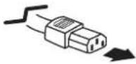 To power cordconnector on yourprojector. To power cordconnector on yourprojector. | For the U.S.A. and CanadaGround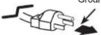 To the AC outlet.(120 V AC) To the AC outlet.(120 V AC) | For Continental Europe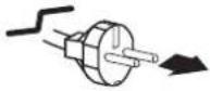 To the AC outlet.(200 - 240 V AC) To the AC outlet.(200 - 240 V AC) | For the U.K. To the AC outlet.(200 - 240 V AC) To the AC outlet.(200 - 240 V AC) |
Turning On the Projector
1 Complete peripheral connections (with a computer, VCR, etc.) before turning on the projector.
2 Connect the projector's AC power cord into an AC outlet. The POWER indicator lights red. Open the lens cap (see pages 9, 65).
3 Press the ON/STAND-BY button on the top control or on the remote control. The POWER indicator lights green and the cooling fans start to operate. The preparation display appears on the screen and the count down starts.
4 After the countdown, the input source that was selected the last time and the lamp control status icon (see page 57) appear on the screen.
5 If there is no signal input when start on the projector, or the current signal is missed while operating the projector, the Video/PC selection window will be displayed on the screen, please move the pointer to input source desired by pressing the Point ▲▼ buttons and press the SELECT button. And then follow the input signal guidance window to correct the signal and connection.
If the projector is locked with a PIN code, PIN code input dialog box will appear. Enter the PIN code as instructed on the next page.

The preparation display will disappear after 30 seconds.
Selected Input Source and Lamp Control

(See page 57 for Lamp control status.)
√Note:
The Filter warning and Lamp replacement icons may appear on the screen depending on the usage state of the projector.
Video / PC selection window

Input signal guidance window

√Note:
- When the Logo select function is set to Off, the logo will not be shown on the screen (p.51).
- When Countdown off or Off is selected in the Display function, the countdown will not be shown on the screen (p.51).
- When the Input Search function is set to On2, the input signal will be searched automatically (p.49).
- When Off is selected in the Display function, the Video/PC selection window and the input signal guidance window are not shown on the screen (p.51).
- If you press the ON/STAND-BY button on the top control or the remote control during the countdown period, you can skip the countdown and go to the normal operations.
Video / PC selection window

Input signal guidance window

Enter a PIN code
Use the Point ▲▼ buttons to enter a number. Press the Point ▶ button to fix the number and move the red frame pointer to the next box. The number changes to *. If you fixed an incorrect number, use the Point ◀ button to move the pointer to the number you want to correct, and then enter the correct number.
Repeat this step to complete entering a four-digit number.
After entering the four-digit number, move the pointer to Set. Press the SELECT button so that you can start to operate the projector.
If you entered an incorrect PIN code, PIN code and the number (****) will turn red for a moment. Enter the correct PIN code all over again.
What is PIN code?
PIN (Personal Identification Number) code is a security code that allows the person who knows it to operate the projector. Setting a PIN code prevents unauthorized use of the projector.
A PIN code consists of a four-digit number. Refer to the PIN code lock function in the Setting Menu on pages 58-59 for locking operation of the projector with your PIN code.

CAUTION ON HANDLING PIN CODE
If you forget your PIN code, the projector can no longer be started. Take a special care in setting a new PIN code; write down the number in a column on page 81 of this manual and keep it on hand. Should the PIN code be missing or forgotten, consult your dealer or service center.
PIN Code Input Dialog Box

OK
After the OK icon disappears, you can operate the projector.
√Note:
- If the PIN code number is not entered within three minutes after the PIN code dialog box appeared, the projector will be turned off automatically.
- The "1234" is set as the initial PIN code at the factory.
Turning Off the Projector
1 Press the ON/STAND-BY button on the top control or on the remote control, and Power off? appears on the screen.
2 Press the ON/STAND-BY button again to turn off the projector. The POWER indicator starts to blink red, and the cooling fans keep running (You can select the level of fans' quietness and speed. See "Fan" on page 60.). At this time, you can unplug the AC power cord even if the fans are still running.
3 When the projector has cooled down enough, the POWER indicator stops blinking and you can turn on the projector.

TO MAINTAIN THE LIFE OF THE LAMP, ONCE YOU TURN THE PROJECTOR ON, WAIT AT LEAST FIVE MINUTES BEFORE TURNING IT OFF.

DO NOT OPERATE THE PROJECTOR CONTINUOUSLY WITHOUT REST. CONTINUOUS USE MAY RESULT IN SHORTENING THE LAMP LIFE. TURN OFF THE PROJECTOR AND LET STAND FOR ABOUT AN HOUR IN EVERY 24 HOURS.

Power off? disappears after 4 seconds.
√Note:
- When the On start function is set to On, the projector will be turned on automatically by connecting the AC power cord to an AC outlet (p.56).
- The running speed of cooling fans is changed according to the temperature inside the projector.
- Do not put the projector in a case before the projector is cooled enough.
- If the WARNING indicator blinks or lights red, see "WARNING indicator" on page 63.
- While the POWER indicator is blinking, the lamp is being cooled down and the projector can not be turned on. Wait until the POWER indicator stops blinking to turn on the projector again.
- The fan rotation will terminate directly if the AC power cord is unplugged immediately after the projector is turned off.
- The projector can be turned on after the POWER indicator turns red. The waiting time to restart will be shortened when the normal power-off processing for fan cooling is completed, compared with the time the AC power cord is immediately unplugged after the power-off.
How to Operate the On-Screen Menu
The projector can be adjusted or set via the On-Screen Menu. The menus have a hierarchical structure, with a main menu that is divided into submenus, which are further divided into other submenus. For each adjustment and setting procedure, refer to respective sections in this manual.
1 Press the MENU button on the top control or the remote control to display the On-Screen Menu.
2 Use the Point ▲▼ buttons to highlight or select a main menu item. Press the Point ▶ or the SELECT button to access the submenu items. (The selected item is highlighted in orange.)
3 Use the Point ▲▼ buttons to select the desired submenu item and press the SELECT button to set or access the selected item.
4 Use the Point ▲▼◀▶ buttons to adjust the setting or switch between each option and press the SELECT button to activate it and return to the submenu.
5 Press the Point ◀ button to return to the main menu. Press the MENU button to exit the On-Screen Menu.
Top Control

Remote Control

On-Screen Menu

Menu Bar
For detailed functions of each menu, see "Menu Tree" on pages 72-73.

① Input
Used to select an input source from Computer 1, Computer 2, Video, S-video or Network (pp.31-32, 41-42).
② PC adjust
Select Auto PC adj., Fine sync, Total dots, Horizontal, Vertical, Clamp, Display area H and Display area V to adjust the parameters to match with the PC input signal format (p.33-36).
③ Image select
For computer source, used to select an image mode among Dynamic, Standard, Real, Blackboard(Green), Colorboard and image 1 - 4 (p.37).
For Video source, used to select an image mode among Dynamic, Standard, Cinema, Blackboard(Green), Colorboard and Image 1-4 (p.44).
④ Image adjust
For computer source, used to adjust computer image [Contrast, Brightness, Color temp., White balance (R/G/B), Sharpness and Gamma] (pp.38-39).
For Video source, used to adjust picture image [Contrast, Brightness, Color, Tint, Color temp., White balance (R/G/B), Sharpness, Gamma, Noise reduction and Progressive] (pp.45-46).
⑤ Screen
For computer source, used to adjust size of the image [ Normal, True, Wide, Full, Custom and Digital zoom +/-] (pp.39-40).
For Video source, used to set size of image [Normal, Wide and Custom] (p.47).
⑥ Sound
Used to adjust the volume or mute the sound (p.28).
⑦ Setting
Used to set the projector's operating configurations (pp.48-61).
⑧ Information
Display the input source information: Input, H-sync freq., V-sync freq., Screen, Language, Lamp status, Lamp counter, Power management, Key lock, PIN code lock and Remote control (p.62).
⑨ Network
See the owner's manual of "Network Set-up and Operation".
⑩ Guide
The key operation is displayed.
Zoom and Focus Adjustment
Rotate the Zoom Lever to zoom in and out.
Rotate the Focus Ring to adjust the focus of the image.

Auto Setup Function
Auto setup function is provided to automatically execute the setting of Auto setup (includes Input search, Auto PC adj. and Auto Keystone functions) in the setting menu by just pressing the AUTO SETUP/CANCEL button on the top control or the AUTO SET/CANCEL button on the remote control. Refer to page 49 for the setting of the Auto setup function.
Top Control

Remote Control

√ Note:
- Auto Keystone corrects vertical distortion only; it does not correct horizontal distortion.
- Auto Keystone can not work when Ceiling feature is set to On in the Setting menu (p.54).
- Perfect correction of the image distortion can not be ensured with the Auto setup function. If the distortion can not be corrected properly by pressing the AUTO SETUP/CANCEL or AUTO SET/CANCEL button, adjust manually by pressing the KEYSTONE button on the remote control or selecting Keystone in the Setting menu (p.50).
- Fine sync, Total dots, Horizontal and Vertical position of some computers can not be fully adjusted with the Auto PC adjustment function. When the image is not provided properly with this operation, manual adjustments are required (pp.35-36).
Keystone Correction
If a projected picture still has keystone distortion after pressing the AUTO SETUP/CANCEL button on the top control or the AUTO SET/CANCEL button on the remote control, correct the image manually as follows:
Press the KEYSTONE button on the top control or on the remote control to switch the Standard (for Vertical/Horizontal)/Corner adjustment. The Standard or Corner adjustment dialog box appears. Use the Point ▲▼◀▶ buttons to correct the Standard or Corner distortion. The Standard or Corner adjustment can be stored (see page 50).
Standard

Reduce the lower width with the Point ▼ button.
Reduce the upper width with the Point ▲ button.

flowchart
graph LR
    A["Rectangle"] --> B["Rectangle"]
    B --> C["Rectangle"]
Reduce the right part with Point ▶ button.
Reduce the left part with Point ◀ button.

flowchart
graph LR
    A["Rectangle"] --> B["Rectangle"]
    B --> C["Rectangle"]
Corner

Press the KEYSTONE button on the top control or on the remote control to switch Corner adjustment, press the SELECT button on the remote control to select the corner you want to adjust.
Reduce the top left corner part with the Point ▶▼ buttons.
Reduce the top right corner part with the Point ◀▼ buttons.

flowchart
graph TD
    A["Device 1"] -->|Press the SELECT button| B["Device 2"]
    B -->|Press the SELECT button| C["Device 3"]
    C -->|Press the SELECT button| D["Device 4"]
    D -->|Press the SELECT button| A
Reduce the bottom left corner part with the Point ▶▲ buttons.
Reduce the bottom right corner part with the Point ◀▲ buttons.
Top Control

Remote Control

√Note:
• The white arrows indicate that there is no correction.
- A red arrow indicates the direction of correction.
- An arrow disappears at the maximum correction.
- If you press and hold the KEYSTONE button for more than 3 seconds while the Standard or Corner dialog box is being displayed, the Standard or Corner correction will be released.
- The Corner pattern can be set to Off, Red, White or Blue in the Corner pattern function. See "Keystone" on page 50.
- The adjustable range is limited depending on the input signal.
- Standard and Corner functions can not be adjusted at the same time. If one of the functions is adjusted, and then the other one will be reset automatically.
- The corner keystone function may be canceled when you set the Auto keystone function to Auto or Manual. To avoid this, it is recommended to set the Auto keystone function to Off while the corner keystone function is activated.
The top left corner adjustment as an example:

flowchart
graph TD
    A["Step 1: Press the Point button"] --> B["Step 2: Press the Point button"]
    B --> C["Step 3: Press the Point button"]
Sound Adjustment
Direct Operation
Volume
Press the VOLUME+/- buttons on the top control or on the remote control to adjust the volume. The volume dialog box appears on the screen for a few seconds.
Mute
Press the MUTE button on the remote control to select On to temporarily turn off the sound. To turn the sound back on, press the MUTE button again to select Off or press the VOLUME +/- buttons. The Mute function is also effective for the AUDIO OUT jack.
Menu Operation
1 Press the MENU button to display the On-Screen Menu. Use the Point ▲▼ buttons to select Sound. Press the Point ▶ or the SELECT button to access the submenu items.
2 Use the Point ▲▼ buttons to select the desired submenu item and press the SELECT button to access the selected item.
Volume
Press the Point ▲ button to turn up the volume; press the Point ▼ button to turn down the volume.
Mute
Press the SELECT button to switch the mute function On/Off. When the sound is turned off, On is displayed. Press the VOLUME +/- buttons again to turn the sound back on.
Top Control

Remote Control


Press the MUTE button to set the Mute function On or Off. The dialog box disappears after 4 seconds.
Sound Menu


Remote Control Operation
Using the remote control for some frequently used operations is advisable. Just pressing one of the buttons enables you to make the desired operation quickly without calling up the On-Screen Menu.
COMPUTER/VIDEO/NETWORK button
Press the COMPUTER, VIDEO or NETWORK button on the remote control to select the input source. See pages 31-32, 41-42 for details.
Refer to the owner's manual of "Network Set-up and Operation" for details about the network input.
FREEZE button
Press the FREEZE button on the remote control to freeze the picture on the screen. To cancel the Freeze function, press the FREEZE button again or press any other button.
Fig.1 will appear on the Screen menu while the Freeze function is working.
Fig.1

INFO. button
Display the input source information: Input, H-sync freq., V-sync freq., Screen, Language, Lamp status, Lamp counter, Power management, Key lock, PIN code lock and Remote control (p.62).
D.ZOOM +/- buttons
Press the D.ZOOM +/- buttons on the remote control to enter to the Digital zoom +/- mode. See page 40 for details.
LAMP button
Press the LAMP button on the remote control to select the lamp mode for changing the brightness on the screen.

High ...... Brighter than the Normal mode.

Normal ..... Normal brightness.

Eco .... Lower brightness reduces the lamp power consumption and extends the lamp life.
Remote Control

√ Note:
See the next page for the description of other buttons.
NO SHOW button
Press the NO SHOW button on the remote control to black out the image. To restore to normal, press the NO SHOW button again or press any other button. The screen changes each time you press the NO SHOW button as follows.
black out → normal → black out……
P-TIMER button
Press the P-TIMER button on the remote control. The P-Timer display 00:00 appears on the screen and the countdown starts (00:00–59:59).
To stop the countdown, press the P-TIMER button. To cancel the P-Timer function, press the P-TIMER button again.
IMAGE button
Press the IMAGE button on the remote control to select a desired image mode of the screen. See pages 37, 44 for details.
SCREEN button
Select the screen size (See pages 39-40, 47 for details).

No show disappears after 4 seconds.

02:02
P-Timer display

√ Note:
See the previous page for the description of other buttons.
Input Source Selection (RGB: Computer 1/Computer 2(Analog))
Direct Operation
&KRRVH HLWKHU Computer 1(RGB) RU Computer 2 (RGB(Analog)) E\ SUHVVLQJ WKH ,1387 EXWWRQ RQ FRQWURO RU SUHVV WKH &20387(5 EXWWRQ RQ WKH UHPRWH FRQWURO
%HIRUH XVLQJ WKHVH EXWWRQV FRUUHFW LQSXW VRXUFH VKRXOG EH VHOHFWHG WKURXJK 0F EHORZ

flowchart
graph TD
    A["INPUT button"] --> B["Computer1 ((RGB) / (Component) / (Scart))"]
    B --> C["Computer2 (RGB(PC digital) / RGB(AV HDCP) / RGB(Analog))"]
    C --> D["Video"]
    D --> E["S-video"]
    E --> F["Network"]
    G["KEYSTONE"] --> A
    H["CLOSE"] --> A

flowchart
graph TD
    A["COMPUTER button"] --> B["COMPUTER1 ((RGB) / (Component) / (Scart))"]
    B --> C["Computer2 (RGB(PC digital) / RGB(AV HDCP) / RGB(Analog))"]
    A --> D["COMPUTER button"]
Menu Operation
1 3UHVV WKH 0(18 EXWWRQ WR GLVSOD\ WKH 2Q 0HQX 8VH WKHY3REQWWRQV WR VHOHFW Input WKHQ SUHVV WKHRORMQWH 6(/&7 EXWWRQ
2 8VH WKH 3RLQW Ÿ EXWWRQV WR VHOHFW HLW
1 RU Computer 2 DQG WKHQ SUHVZV EWKHRRLQW
DFFHVV WKH VXEPHQX LWHPV
3 :KHQ Computer 1 LV VHOHFWHG XVH WKH 3RLQ EXWWRQV WR VHOHFW RGB DQG WKHQ SUHVV EXWWRQ
:KHQ Computer 2 LV VHOHFWHG XVPIZ WKH 3RLQW Sound EXWWRQV WR VHOHFW RGB(Analog) DQG WKHQ SUHVV WKH 6/(&7 EXWWRQ Information


√Note:
:KHQ WKH ,QSXW 6HDUFK IXQFWLRQ LV VHW WPL On1 RU On2 LQ WKH \$XWR VHWXS IXQFWLRQ WKH LQSXW VLJQDO ZLOO EH VHDUFKHG DXWRPDWLFDOO\ S

Input Source Selection (RGB(PC digital), RGB(AV HDCP))
Direct Operation
Choose Computer 2(RGB(PC digital)) or Computer 2(RGB(AV HDCP)) by pressing the INPUT button on the top control or press the COMPUTER button on the remote control.
Before using these buttons, correct input source should be selected through Menu operation as described below.

flowchart
graph TD
    A["INPUT button"] --> B["Computer1 ((RGB) / (Component) / (Scart))"]
    B --> C["Computer2 (RGB(PC digital) / RGB(AV HDCP) / RGB(Analog))"]
    C --> D["Video"]
    D --> E["S-video"]
    E --> F["Network"]
    G["KEYSTONE MENU"] --> A

flowchart
graph TD
    A["COMPUTER button"] --> B["COMPUTER1 ((RGB) / (Component) / (Scart))"]
    A --> C["COMPUTER2 (RGB(PC digital) / RGB(AV HDCP) / RGB(Analog))"]
Menu Operation
1 Press the MENU button to display the On-Screen Menu. Use the Point ▲▼ buttons to select Input and then press the Point ▶ or the SELECT button.
2 Use the Point ▲▼ buttons to select Computer 2 and then press the Point ▶ button to access the submenu item.
3 Use the Point ▲▼ buttons to select RGB(PC digital) or RGB(AV HDCP) and then press the SELECT button.
Input Menu


√Note:
- HDCP (High-bandwidth Digital Content Protection) is a system for protecting digital entertainment content delivered by DVI (Digital Visual Interface) from being copied. The specification of HDCP is decided and controlled by Digital Content Protection, LLC. Should the specification be changed, this projector may not display the digital content protected by HDCP.
- When the Input Search function is set to On1 or On2, the input signal will be searched automatically (p.49).
Computer System Selection
This projector automatically tunes to various types of computers with its Multi-scan system and Auto PC adjustment. If a computer is selected as a signal source, this projector automatically detects the signal format and tunes to project a proper image without any additional settings. (Signal formats provided in this projector are shown on pages 75-76)
One of the following messages may appear when:
Auto
The projector can not recognize the connected signal conforming to the provided PC Systems.
Auto is displayed on the System Menu box and the Auto PC adjustment function works to display proper images. If the image is not projected properly, a manual adjustment is required (pp.35-36).
......
There is no signal input from the computer. Check the connection between your computer and the projector. (See "Troubleshooting" on pp.68-70.)
Mode 1
The preset system is manually adjusted in the PC adjust Menu. The adjusted data can be stored in Mode 1-5 (pp.35-36).
SVGA 1
PC Systems provided in this projector is chosen. The projector chooses a proper system provided in the projector and displays it.
*Mode 1 and SVGA 1 are examples.
PC System Menu

The PC System Menu Selected system is displayed.
Selecting Computer System Manually
PC system can also be selected manually.
1 Press the MENU button to display the On-Screen Menu. Use the Point ▲▼ buttons to select Input and then press the Point ▶ or the SELECT button.
2 Use the Point ▲▼ buttons to select System and then press the Point ▶ or the SELECT button.
3 Use the Point ▲▼ buttons to select the desired system and then press the SELECT button.
PC System Menu
Customized Mode (1–5) set in the PC adjust Menu (pp.35-36).

Systems in this dialog box can be selected.
Auto PC adjustment
Auto PC adjustment function is provided to automatically adjust Fine sync, Total dots, Horizontal and Vertical to conform to your computer.
Menu Operation
Auto PC adj.
1 Press the MENU button to display the On-Screen Menu. Use the Point ▲▼ buttons to select PC adjust and then press the Point ▶ or the SELECT button.
2 Use the Point ▲▼ buttons to select Auto PC adj. and then press the SELECT button.
To store adjustment parameters
The adjusted parameters from the Auto PC adjustment can be stored in the projector. Once the parameters are stored, the setting can be done just by selecting a Mode (1–5) in the PC System Menu (see page 33). See also Store on page 36.
PC adjust Menu


Use Point ▲▼ buttons to select Auto PC adj. and press the SELECT button. Please wait... appears while the Auto PC adjustment is in process.

√Note:
- Fine sync, Total dots, Horizontal and Vertical position of some computers can not be fully adjusted with the Auto PC adjustment function. When the image is not provided properly with this operation, manual adjustments are required (pp.35-36).
- The Auto PC adjustment can not be operated when 480i, 575i, 480p, 575p, 720p, 1035i or 1080i is selected in the PC System Menu (p.33), or when the signal is coming from the DVI terminal.
Manual PC adjustment
Some computers employ special signal formats which may not be tuned by Multi-scan system of this projector. Manual PC adjustment enables you to precisely adjust several parameters to match those signal formats. The projector has five independent memory areas to store those parameters manually adjusted. It allows you to recall the setting for a specific computer.
1 Press the MENU button to display the On-Screen Menu. Use the Point ▲▼ buttons to select PC adjust and then press the Point ▶ or the SELECT button.
2 Use the Point ▲▼ buttons to select the desired item and then press the SELECT button to display the adjustment dialog box. Use the Point ◀▶ buttons to adjust the setting value.
Fine sync
Use the Point ◀▶ buttons to adjust the value, eliminating a flicker from the image displayed (from 0 to 31).
Total dots
Use the Point ◀▶ buttons to adjust the number of total dots in one horizontal period to match your PC image.
Horizontal
Use the Point ◀▶ buttons to adjust the horizontal picture position.
Vertical
Use the Point ◀▶ buttons to adjust the vertical picture position.
Clamp
Use the Point ◀▶ buttons to adjust the clamp level. When the image has dark bars, try this adjustment.
Display area H
Use the Point ◀▶ buttons to adjust the horizontal area displayed by this projector.
Display area V
Use the Point ◀▶ buttons to adjust the vertical area displayed by this projector.
PC adjust Menu


Reset
To reset the adjusted data, select Reset and press the SELECT button. A confirmation box appears and then select Yes. All adjustments will return to their previous figures.
Mode free
To clear the stored data, select Mode free and then press the Point ▶ or the SELECT button. Move the highlight to the mode that you want to clear and then press the SELECT button.
Store
To store the adjusted data, select Store and then press the Point ▶ or the SELECT button. Move the highlight to one of the Modes 1 to 5 in which you want to store, and then press the SELECT button.
√ Note:
- Display area (H/V) can not be selected when 480i, 575i, 480p, 575p, 720p, 1035i or 1080i is selected in the PC System Menu (p.33).
- When input computer signal to the projector, PC adjust will become available.
Mode free

Values of Total dots, Horizontal, Vertical, Display area H and Display area V.
Store

Press MENU button to close this dialog box.
Press SELECT button to store adjusted data.
Image Mode Selection
Direct Operation
Select the desired image mode among Dynamic, Standard, Real, Blackboard (Green), Colorboard, Image 1, Image 2, Image 3 and Image 4 by pressing the IMAGE button on the remote control.
Menu Operation
1 Press the MENU button to display the On-Screen Menu. Use the Point ▲▼ buttons to select Image select and then press the Point ▶ or the SELECT button.
2 Use the Point ▲▼ buttons to select the desired item and then press the SELECT button.
Dynamic
For viewing pictures in a bright room.
Standard
Normal picture mode preset on the projector.
Real
Picture mode with improved halftone for graphics.
Blackboard (Green)
For the image projected on a blackboard.
This mode helps enhance the image projected on a blackboard. This is mainly effective on a green colored board, not truly effective on a black colored board.
Colorboard
Use the Point ▲▼ buttons to select Colorboard and then press the Point ▶ or the SELECT button. Use the Point ▲▼ buttons to select the desired item and then press the SELECT button.
At the time of simple projection on the colored wall, you can get the close color image to the color image projected on a white screen by selecting the similar color to the wall color from the preset four colors.
Image 1-4
For viewing with the user preset image mode in the Image adjust Menu (see pages 38-39). This Image memory is provided in each computer, component and video input source.
Remote Control

IMAGE button

flowchart
graph TD
    A["Dynamic"] --> B["Standard"]
    B --> C["Real"]
    C --> D["Blackboard(Green)"]
    D --> E["Colorboard"]
    E --> F["Image 1"]
    F --> G["Image 2"]
    G --> H["Image 3"]
    H --> I["Image 4"]
    I --> A
Image Select Menu

Image Adjustment
1 Press the MENU button to display the On-Screen Menu. Use the Point ▲▼ buttons to select Image adjust and then press the Point ▶ or the SELECT button.
2 Use the Point ▲▼ buttons select the desired item and then press the SELECT button to display the adjustment dialog box. Use the Point ◀▶ buttons to adjust the setting value.
Contrast
Press the Point ◀ button to decrease the contrast; press the Point ▶ button to increase the contrast (from 0 to 63).
Brightness
Press the Point ◀ button to decrease the brightness; press the Point ▶ button to increase the brightness (from 0 to 63).
Color temp.
Use the Point ◀▶ buttons to select the desired Color temp. level (XLow, Low, Mid or High).
White balance (Red)
Press the Point ◀ button to lighten red tone; press the Point ▶ button to deepen red tone (from 0 to 63).
White balance (Green)
Press the Point ◀ button to lighten green tone; press the Point ▶ button to deepen green tone (from 0 to 63).
White balance (Blue)
Press the Point ◀ button to lighten blue tone; press the Point ▶ button to deepen blue tone (from 0 to 63).
Sharpness
Press the Point ◀ button to decrease the sharpness of the image; press the Point ▶ button to increase the sharpness of the image (from 0 to 15).
Gamma
Use the Point ◀▶ buttons to adjust the gamma value obtain a better balance of contrast (from 0 to 15).
Reset
To reset the adjusted data, select Reset and press the SELECT button. A confirmation box appears and then select Yes. All adjustments will return to their previous figures.
Image Adjust Menu

√Note:
- When White balance Red, Green or Blue is adjusted, Color temp. will change to User. - When Blackboard(Green) or Colorboard is selected in Image select, Color temp. will change to Blackboard or Colorboard.
Store
To store the adjusted data, select Store and press the Point ▶ or the SELECT button. Use the Point ▲▼ buttons to select one from Image 1 to 4 and press the SELECT button. A confirmation box appears and then select Yes. Stored data can be called up by selecting an Image (1–4) in the Image Mode Selection on page 37.

A confirmation box appears and then select Yes.
Screen Size Adjustment
This projector has the picture screen resize function, which enables you to customize the image size.
1 Press the MENU button to display the On-Screen Menu. Use the Point ▲▼ buttons to select Screen and then press the Point ▶ or the SELECT button.
2 Use the Point ▲▼ buttons select the desired item and then press the SELECT button.
Normal
Provide the image to fit the screen size.
True
Provide the image in its original size. When the image size is larger than the screen size (1024 x 768), the projector enters to the panning mode automatically. Use the Point ▲▼◀▶buttons to pan the image. When adjusted, the arrows will turn red. When reached to the correction limits, the arrows will disappear.
Wide
Provide the image to fit the wide video aspect ratio (16:9) by expanding the image width uniformly. This function can be used for providing a squeezed video signal at 16:9.
Full
Provide the full screen image.
Screen Menu


√ Note:
- The Screen Menu, except for Normal and Custom, can not be operated when 720p, 1035i or 1080i is selected in the PC System Menu (p.33).
- This projector can not display any resolution higher than 1920 x 1200. If your computer's screen resolution is higher than it, reset the resolution to the lower before connecting to the projector.
- The image data in other than 1024 x 768 is modified to fit the screen size in initial mode.
- True, Full and Digital zoom +/- can not be selected when 480i, 575i, 480p or 575p is selected in the PC System Menu (p.33).
Custom
Adjust the screen scale and position manually with this function.
Press the Point ▶ button at Custom and the Custom is displayed on the screen, you can use the Point ▲▼ buttons to choose the item you want to adjust.
Scale H/V .... Adjust the Horizontal/Vertical screen scale.
H&V...... When set to On, the aspect ratio is fixed. Scale V appears dimmed and becomes unavailable. Adjust Scale H, then the screen scale is automatically modified based on the aspect ratio.
Position H/V ..... Adjust the Horizontal/Vertical screen position.
Common .... Save the adjusted scale to all the inputs. Press the SELECT button at Common to display a confirmation box. To save the scale, press the SELECT button at Yes. When Custom is selected, the saved scale is used.
Reset .... Reset the all adjusted values. Press the SELECT button at Reset to display a confirmation box. To reset, press the SELECT button at Yes.
For zooming in and out the images
Digital zoom +
Select Digital zoom +. The On-Screen Menu disappears and D. zoom + appears. Press the SELECT button to expand the image size. Use the Point ▲▼◀▶ buttons to pan the image. The Panning function can work only when the image is larger than the screen size.
A projected image can be also expanded by pressing D.ZOOM + button on the remote control.
Digital zoom -
Select Digital zoom -. The On-Screen Menu disappears and D. zoom – appears. Press the SELECT button to compress image size.
The projected image can be also compressed by pressing the D.ZOOM - button on the remote control.
To exit the Digital zoom +/- mode, press any button except the D.ZOOM +/- buttons, SELECT and Point buttons.
To return to the previous screen size, select a screen size from the Screen Size Adjustment Menu or select an input source from the Input Source Selection Menu (see pages 31-32) again or adjust the screen size with the D.ZOOM +/- buttons.
Custom

√Note:
- When no signal is detected, Normal is set automatically and the Aspect dialog box disappears.
- The adjustable range for Scale H/V and Position H/V is limited depending on the input signal.
Remote Control

√Note:
- The panning function may not operate properly if the stored Mode in the PC adjust Menu is used (p.36).
- The minimum compression ratio is limited depending on the input signal, when the Keystone function is working or when the custom is selected for the screen size.
- True, Full and Digital zoom +/- can not be selected when 480i, 575i, 480p or 575p is selected in the PC System Menu (p.33).
- Digital zoom +/- can not be selected when Full or True is selected.
- Digital zoom – can not be operated when Custom is selected.
Input Source Selection (Video, S-video)
Direct Operation
Choose Video or S-video by pressing the INPUT button on the top control or the VIDEO button on the remote control.
Remote Control

flowchart
graph TD
    A["COMPUTER"] --> B["VIDEO"]
    C["VIDEO button"] --> D["Video"]
    E["VIDEO button"] --> F["S-video"]
    G["VIDEO button"] --> H["Video"]
    I["VIDEO button"] --> J["S-video"]

flowchart
graph TD
    A["INPUT button"] --> B["Computer1 ((RGB) / (Component) / (Scart))"]
    B --> C["Computer2 (RGB(PC digital) / RGB(AV HDCP) / RGB(Analog))"]
    C --> D["Video"]
    D --> E["S-video"]
    E --> F["Network"]
    G["INPUT INPUT"] --> H["KEYSTONE"]
    G --> I["MENU"]
    G --> J["VOLUME"]
    G --> K["SHIFT"]
    G --> L["SELECT"]
Menu Operation
1 Press the MENU button to display the On-Screen Menu. Use the Point ▲▼ buttons to select Input and then press the Point ▶ or the SELECT button.
2 Use the Point ▲▼ buttons to select either Video or S-video and then press the SELECT button.
Video When video input signal is connected to the VIDEO jack, select Video.
S-video When video input signal is connected to the S-VIDEO jack, select S-video.
Input Menu


√Note:
- Network is for the Network function. See the owner's manual of "Network Set-up and Operation".
- When the Input Search function is set to On1 or On2 in the Auto setup function, the input signal will be searched automatically (p.49).
Input Source Selection (Component, RGB Scart 21-pin)
Direct Operation
Choose Computer 1(Component) or Computer 1(Scart) by pressing the INPUT button on the top control or press the COMPUTER button on the remote control.
Before using these buttons, correct input source should be selected through Menu operation as describe below.

flowchart
graph TD
    A["COMPUTER button"] --> B["Computer1 ((RGB) / (Component) / (Scart))"]
    B --> C["Computer2 (RGB(PC digital) / RGB(AV HDCP) / RGB(Analog))"]
    A --> D["COMPUTER"]
Menu Operation
1 Press the MENU button to display the On-Screen Menu. Use the Point ▲▼ buttons to select Input and then press the Point ▶ or the SELECT button.
2 Use the Point ▲▼ buttons to select Computer 1 and then press the Point ▶ button.
3 Use the Point ▲▼ buttons to select Component or RGB(Scart) and then press the SELECT button.
Component
When the input source is coming from video equipment connected to the COMPUTER IN 1/COMPONENT IN terminal with a Component-VGA Cable, select Component.
RGB (Scart)
When the input source is coming from video equipment connected to the COMPUTER IN 1/COMPONENT IN terminal with a Scart-VGA Cable, select RGB (Scart).
√Note:
- Network is for the Network function. See the owner's manual of "Network Set-up and Operation".
- When the Input Search function is set to On1 or On2, the input signal will be searched automatically (p.49).

flowchart
graph TD
    A["INPUT button"] --> B["KEYST"]
    A --> C["INE"]
    A --> D["CANCEL"]
    B --> E["Computer1 ((RGB) / (Component) / (Scart))"]
    C --> F["Computer2 (RGB(PC digital) / RGB(AV HDCP) / RGB(Analog))"]
    D --> G["Video"]
    G --> H["S-video"]
    H --> I["Network"]
Input Menu


Video System Selection
1 Press the MENU button to display the On-Screen Menu. Use the Point ▲▼ buttons to select Input and then press the Point ▶ or the SELECT button.
2 Use the Point ▲▼ buttons to select Video, S-video or Computer 1(Component) and then press the SELECT button.
3 Use the Point ▲▼ buttons to select System and then press the Point ▶ or the SELECT button. Use the Point ▲▼ buttons to select the desired system and then press the SELECT button.
Video or S-video
Auto
The projector automatically detects an incoming video system, and adjusts itself to optimize its performance. When Video System is PAL-M or PAL-N, select the system manually.
PAL/SECAM/NTSC/NTSC4.43/PAL-M/PAL-N
If the projector can not reproduce proper video image, select a specific broadcast signal format from among PAL, SECAM, NTSC, NTSC 4.43, PAL-M and PAL-N.
AV System Menu (Video or S-video)

Component
Auto
The projector automatically detects an incoming video signal, and adjusts itself to optimize its performance.
COMPONENT VIDEO SIGNAL FORMAT
If the projector can not reproduce proper video image, select a specific component video signal format among 480i, 575i, 480p, 575p, 720p, 1035i, 1080i and 1080p.
AV System Menu (Component)

√Note:
The AV System Menu can not be selected when selecting RGB (Scart).
Image Mode Selection
Direct Operation
Select the desired image mode among Dynamic, Standard, Cinema, Blackboard (Green), Colorboard, Image 1, Image 2, Image 3 and Image 4 by pressing the IMAGE button on the remote control.
Menu Operation
1 Press the MENU button to display the On-Screen Menu. Use the Point ▲▼ buttons to select Image select and then press the Point ▶ or the SELECT button.
2 Use the Point ▲▼ buttons to select the desired item and then press the SELECT button.
Dynamic
For viewing pictures in a bright room.
Standard
Normal picture mode preset on the projector.
Cinema
Picture mode adjusted with fine tone.
Blackboard (Green)
For the image projected on a blackboard. This mode helps enhance the image projected on a blackboard. This is mainly effective on a green colored board, not truly effective on a black colored board.
Colorboard
Use the Point ▲▼ buttons to select Colorboard and then press the Point ▶ or the SELECT button. Use the Point ▲▼ buttons to select the desired item and then press the SELECT button.
At the time of simple projection on the colored wall, you can get the close color image to the color image projected on a white screen by selecting the similar color to the wall color from the preset four colors.
Image 1-4
For viewing with the user preset image mode in the Image adjust Menu (see pages 45-46). This Image memory is provided in each computer, component and video input source.
Remote Control

IMAGE button

flowchart
graph TD
    A["Dynamic"] --> B["Standard"]
    B --> C["Cinema"]
    C --> D["Blackboard (Green)"]
    D --> E["Colorboard"]
    E --> F["Image 1"]
    F --> G["Image 2"]
    G --> H["Image 3"]
    H --> I["Image 4"]
    I --> A
Image Select Menu

Image Adjustment
1 Press the MENU button to display the On-Screen Menu. Use the Point ▲▼ buttons to select Image adjust and then press the Point ▶ or the SELECT button.
2 Use the Point ▲▼ buttons select the desired item and then press the SELECT button to display the adjustment dialog box. Use the Point ◀▶ buttons to adjust the setting value.
Contrast
Press the Point ◀ button to decrease the contrast; press the Point ▶ button to increase the contrast (from 0 to 63).
Brightness
Press the Point ◀ button to decrease the brightness; press the Point ▶ button to increase the brightness (from 0 to 63).
Color
Press the Point ◀ button decrease the intensity of the color; press the Point ▶ button increase the intensity of the color (from 0 to 63).
Tint
Press the Point ◀▶ buttons to adjust the tint value to get a proper color balance (from 0 to 63).
Color temp.
Use the Point ◀▶ buttons to select the desired Color temp. level (XLow, Low, Mid or High).
White balance (Red)
Press the Point ◀ button to lighten red tone; press the Point ▶ button to deepen red tone (from 0 to 63).
White balance (Green)
Press the Point ◀ button to lighten green tone; press the Point ▶ button to deepen green tone (from 0 to 63).
White balance (Blue)
Press the Point ◀ button to lighten blue tone; press the Point ▶ button to deepen blue tone (from 0 to 63).
Image adjust Menu

√ Note:
- When White balance Red, Green or Blue is adjusted, the Color temp. level will change to User.
- Tint can not be selected when the video system is PAL, SECAM, PAL-M or PAL-N (p.43).
- When Blackboard(Green) or Colorboard is selected in Image select, Color temp. will change to Blackboard or Colorboard.
Sharpness
Press the Point ◀ button to decrease the sharpness of the image; Press the Point ▶ button to increase the sharpness of the image (from 0 to 15).
Gamma
Use the Point ◀▶ buttons to adjust the gamma value to obtain a better balance of contrast (from 0 to 15).
Noise reduction
Noise interference on the screen can be reduced. Select one of the following options to get smoother images.
Off ...... Disabled.
L1 ...... Lower reduction.
L2 ...... Higher reduction.
Progressive
An interlaced video signal can be displayed in progressive mode. Select one of the following options.
Off ..... Disabled.
L1 ...... For an active picture.
L2 ...... For a still picture.
Film ...... For watching a film. With this function, the projector reproduces pictures faithful to the original film quality.
Reset
To reset the adjusted data, select Reset and press the the SELECT button. A confirmation box appears and then select Yes. All adjustments will return to their previous figures.
Store
To store the adjusted data, select Store and press the Point ▶ or the SELECT button. Use the Point ▲▼ buttons to select one from Images 1 to 4 and press the SELECT button.
A confirmation box appears and then select Yes. Stored data can be called up by selecting an Image (1-4) in the Image Mode Selection on page 44.
√Note:
Noise reduction and Progressive can not be selected when 480p, 575p, 720p, 1035i or 1080i is selected (p.43).
Store Menu


A confirmation box appears and then select Yes.
Screen Size Adjustment
This projector has the picture screen resize function, which enables you to customize the image size.
1 Press the MENU button to display the On-Screen Menu. Use the Point ▲▼ buttons to select Screen and then press the Point ▶ or the SELECT button
2 Use the Point ▲▼ buttons select the desired item and then press the SELECT button.
Normal
Provide the image to fit the screen size while maintaining the aspect ratio of input signal.
Wide
Provide the image at the 16:9 wide screen ratio.
Custom
Adjust the screen scale and position manually with this function.
Press the Point ▶ button at Custom and the Custom is displayed on the screen, you can use the Point ▲▼ buttons to choose the item you want to adjust.
Scale H/V .... Adjust the Horizontal/Vertical screen scale. H&V.... When set to On, the aspect ratio is fixed. Scale V appears dimmed and becomes unavailable. Adjust the Scale H, then the screen scale is automatically modified based on the aspect ratio.
Position H/V.....Adjust the Horizontal/Vertical screen position.
Common .... Save the adjusted scale to all the inputs. Press the SELECT button at Common to display a confirmation box. To save the scale, press the SELECT button at Yes, When Custom is selected, the saved scale is used.
Reset .... Reset the all adjusted values. Press the SELECT button at Reset to display a confirmation box. To reset, press the SELECT button at Yes.
Screen Menu

flowchart
graph TD
    A["Input"] --> B["PC adjust"]
    B --> C["Image select"]
    C --> D["Image adjust"]
    D --> E["Screen"]
    E --> F["Sound"]
    F --> G["Setting"]
    G --> H["Information"]
    H --> I["Network"]
    J["Normal Wide"] --> K["Custom more..."]
    L["VOUT Exit"] --> M["Back"]
    N["Move"] --> O["Next"]
    P["SELECT Select"] --> Q["Select"]
    R["Input"] --> S["PC adjust"]
    S --> T["Image select"]
    T --> U["Image adjust"]
    U --> V["Screen"]
    V --> W["Sound"]
    W --> X["Setting"]
    X --> Y["Information"]
    Y --> Z["Network"]
    AA["Custom Aspect"] --> AB["Scale H 0"]
    AB --> AC["Scale V 0"]
    AC --> AD["H&V Off"]
    AD --> AE["Position H 0"]
    AE --> AF["Position V 0"]
    AF --> AG["Common Reset"]
    AG --> AH["Reset"]
    AI["VOUT Exit"] --> AJ["Back"]
    AK["Move"] --> AL["----"] --> AM["SELECT Next"]
    AN["Scale H 32"] --> AO["Exit: Scroll Adjust Back"]
√Note:
- When no signal is detected, Normal is set automatically and the Aspect dialog box disappears.
- The adjustable range for Scale H/V and Position H/V is limited depending on the input signal.
- Wide, Zoom and Natural wide can not be operated when 720p, 1035i or 1080i is selected in the AV System Menu (p.43).
- The corner pattern mode is disable when in Custom mode.
Setting
This projector has a Setting menu that allows you to set up the other various functions described below.
1 Press the MENU button to display the On-Screen Menu. Press the Point ▲▼ buttons to select Setting and press the Point ▶ or the SELECT button to access the submenu items.
2 Use the Point ▲▼ buttons to select the desired item and then press the Point ▶ or the SELECT button to access the selected item.
3 Use the Point ▲▼ buttons to select the desired item and then press the SELECT button.
Setting Menu


Language
The language used in the On-Screen Menu is available in English, German, French, Italian, Spanish, Portuguese, Dutch, Swedish, Finnish, Polish, Hungarian, Romanian, Russian, Chinese, Korean, Japanese and Thai.
Menu position
This function is used to change the position of the On-Screen Menu. Select Menu position and press the Point ▶ or the SELECT button.
The Menu position changes each time you press SELECT button as follows. the top left → the top right → the center → the bottom left → the bottom right → the top left →.....
Language

Auto setup
This function enables Input search, Auto Keystone correction and Auto PC adjustment by pressing the AUTO SETUP/CANCEL button on the top control or the AUTO SET/CANCEL button on the remote control. Settings for those functions can be altered as follows:
Input search
This function detects the input signal automatically. When a signal is found, the search will stop. Use the Point ▲▼ buttons to select one of the following options.
Off .....Input search will not work.
On 1 ...Input search works under the following situation.
- When pressing the AUTO SETUP/CANCEL button on the top control.
- When pressing the AUTO SET/CANCEL button on the remote control.
On 2 ...Input search works under the following situation.
- When turning on the projector by pressing the ON/STAND-BY button on the top control or the remote control.
- When pressing the AUTO SET/CANCEL button on the remote control.
- When pressing the AUTO SETUP/CANCEL button on the top control.
- When the current input signal is cut off.*
* If the No show or Freeze function is active, cancel it to activate the Input search. It is also unavailable when On-Screen menu is displayed.
Auto PC adj.
On . . . . . Enables Auto PC adjustment when pressing the AUTO SET/CANCEL button on the remote control or the AUTO SETUP/CANCEL button on the top control.
Off ..... Disables Auto PC adjustment.
Auto Keystone
Auto .... Always works and corrects keystone distortion according to the projector's tilt.
Manual . . Works only when pressing the AUTO SETUP/CANCEL button on the top control or the AUTO SET/CANCEL button on the remote control.
Off ..... Disables Auto Keystone.
√Note:
- While Input search is set to On 1 or On 2, the status of Input and Lamp are displayed every time the signal is switched.
- Only the last selected input source can be detected.
- If the INPUT button on the top control or the COMPUTER, VIDEO or NETWORK buttons on the remote control is pressed during Input search is in progress, Input search will stop and go back to the previous input signal.
- Input search, Auto PC adj. and Auto Keystone can not be set Off at the same time.
Auto setup Menu

√Note:
- Auto Keystone corrects vertical distortion only, not correct horizontal distortion.
- The Auto Keystone function can not work when the Ceiling is set On in the Setting menu (p.54).
- Perfect correction of the image distortion can not be ensured with the Auto setup function. If the distortion is not corrected properly by pressing the AUTO SETUP/CANCEL button, adjust manually by pressing the KEYSTONE button on the remote control or selecting Keystone in the Setting menu (pp.27,50).
- Fine sync, Total dots, Horizontal and Vertical of some computers can not be fully adjusted with the Auto PC adjustment function. When the image is not provided properly with this operation, manual adjustments are required (pp.35-36).
Keystone
This function is used to adjust keystone distortion of the projected image. Use the Point ▲▼ buttons to choose the item you want to adjust.
Standard
Adjust the Horizontal/Vertical keystone distortion of the projected image.
Corner correction
Adjust the corner distortion of the projected image.
Corner pattern
Choose a Corner pattern mode among Red, White, Blue, and Off.
Store
Store .....Keep the keystone correction even when the AC power cord is unplugged.
Reset.....Release the keystone correction when the AC power cord is unplugged.
Press the KEYSTONE button on the remote control to switch the Standard (for Vertical/Horizontal) /Corner correction adjustment. The Standard or Corner correction adjustment dialog box appears. Use the Point ▲▼◀▶ buttons to correct the Standard or Corner distortion (p.27).
Keystone

Background
Select the background screen for when no input signal is detected. Press the Point ▲▼ buttons to switch between each option.
Blue . . . Blue colored background.
User . . . The image you captured.
Black . . Black colored background.
Display
This function decides whether to display On-Screen Displays.
Off.... Hide the On-Screen Displays except; Countdown Off..... Show the input image instead of the countdown when turning on the projector. Use this function when you want to project the image as early as possible even when the lamp is not bright enough.
On .... Show all the On-Screen displays. Use this function when you want to project images after the lamp becomes bright enough. The factory default setting is in this option.
- On-Screen Menu
• Power off? (p.23)
• No signal for Power management (p.55) - Please wait ...
- Arrows for the True function in the Screen Menu (p.39)
- P-Timer
Logo (Logo and Logo PIN code lock settings)
This function allows you to customize the screen logo with Logo select, capture, Logo PIN code lock and Logo PIN code change functions.
√ Note:
When On is selected in the Logo PIN code lock function, Logo select, capture and Logo PIN code change can not be selected.
Logo select
This function decides on the starting-up display from among following options.
Off ...... Show the countdown display only.
Default .... Show the factory-set logo.
User ...... Show the image you captured.
Logo select Menu

Capture
This function enables you to capture an image being projected to use it for a starting-up display or interval of presentations.
Select Capture and press the SELECT button.
A confirmation box appears and select Yes to capture the projected image.
After capturing the projected image, go to the Logo select function and set it to User. Then the captured image will be displayed the next time you turn on the projector or when you press the NO SHOW button (see page 30).
To cancel the capture function, select Yes in the "Quit?" confirmation box.
√ Note:
- Before capturing an image, select Standard in the Image Select Menu to capture a proper image (pp.37, 44).
- A signal from a computer can be captured up to XGA (1024 x 768). A signal from video equipment can be captured except for 720p, 1035i and 1080i.
- When capturing the image that has been adjusted by the Keystone function, the adjusted data is automatically reset and the projector captures an image without keystone correction.
- When Logo PIN code lock is set to On, capture can not be selected.
- When starting to capture a new image, the previously stored image is cleared even if you cancel the capturing.
- When there is no captured image or it is interrupted while capturing an image, User can not be selected, you can only switch between Default and Off.
Logo PIN code lock
This function prevents an unauthorized person from changing the screen logo.
Off .... The screen logo can be changed freely from the Logo Menu (p.51).
On .... The screen logo can not be changed without a Logo PIN code.
If you want to change the Logo PIN code lock setting, press the SELECT button and the Logo PIN code dialog box appears. Enter a Logo PIN code by following the steps below. The initial Logo PIN code is set to "4321" at the factory.
Capture

flowchart
graph TD
    A["Input"] --> B["PC adjust"]
    B --> C["Image select"]
    C --> D["Image adjust"]
    D --> E["Screen"]
    E --> F["Sound"]
    F --> G["Setting"]
    G --> H["Information"]
    H --> I["Network"]

    J["Logo Select User"] --> K["Capture"]
    K --> L["Logo PIN code lock Off"]
    K --> M["Logo PIN code change"]

    N["OK?"] --> O{Yes}
    O --> P{No}
    P --> Q["Move Select"]

    R["Quit?"] --> S{Yes}
    S --> T{No}
    T --> U{Move Select}
Logo PIN code lock

Enter a Logo PIN code
Use the Point ▲▼ buttons to enter a number. Press the Point ▶ button to fix the number and move the red frame pointer to the next box. The number changes to you fixed an incorrect number, use the Point ◀ button to move the pointer to the number you want to correct, and then enter the correct number.
Repeat this step to complete entering a four-digit number.
After entering the four-digit number, move the pointer to Set. Press the SELECT button so that you can start to operate the projector.
If you entered an incorrect Logo PIN code, Logo PI code and the numbe* * * *) will turn red for a moment. Enter the correct Logo PIN code all over again.
Change the Logo PIN code lock setting
Use the Point ▲▼ buttons to switch On or Off, and then press the SELECT button to close the dialog box.
Logo PIN code change
Logo PIN code can be changed to your desired four-digit number. Press the Point ▼ button to select Logo PIN code change and then press the SELECT button. The New Logo PIN code input dialog box appears. Set a new Logo PIN code.
Be sure to note the new Logo PIN code and keep it on hand. If you lost the number, you could no longer change the Logo PIN code setting. For details on PIN code setting, refer to "PIN code lock" on pages 58-59.
CAUTION:
WHEN YOU HAVE CHANGED THE LOGO PIN CODE, WRITE DOWN THE NEW PIN CODE IN COLUMN OF THE LOGO PIN CODE NO. MEMO ON PAGE 81, AND KEEP IT SECURELY. SHOULD THE LOGO PIN CODE BE LOST OR FORGOTTEN, THE LOGO PIN CODE SETTING CAN NO LONGER BE CHANGED.
Enter a Logo PIN code

Change the Logo PIN code lock setting

Change the Logo PIN code

flowchart
graph TD
    A["Input"] --> B["PC adjust"]
    B --> C["Image select"]
    C --> D["Image adjust"]
    D --> E["Screen"]
    E --> F["Sound"]
    F --> G["Setting"]
    G --> H["Information"]
    H --> I["Network"]

    J["Logo"] --> K["Logo Select User"]
    K --> L["Capture"]
    L --> M["Logo PIN code lock Off"]
    M --> N["Logo PIN code change"]

    O["Menu"] --> P["Menu Exit Back Move Stop Next"]

    Q["Logo PIN code"] --> R["Set Cancel"]
    S["New logo PIN code"] --> T["3 4 1 7"]
    U["OK ?"] --> V["Yes No"]
    W["Menu"] --> X["Menu Exit Move Select"]
USB Terminal
This function provides the following options for the USB terminal.
Mouse control ... When using the remote control as a mouse control, set this option. (p.15)
Display ... When using "USB display" function, set this option. The image and sound are sent to the projector by connecting the computer to the projector with a USB cable. Refer to the owner's manual of "Network Set-up and Operation For Windows".
Ceiling
When this function is set to On, the picture will be bottom and left/right reversed. This function is used to project the image from a ceiling-mounted projector.
Rear
When this function is set to On, the picture will be left/right reversed. This function is used to project the image from rear of the screen.
Pointer
You can emphasize a part of the projected image with this function. Use the Point ▲▼ buttons to choose Spotlight (Large, Middle or Small), Arrow, Finger or Dot and press the SELECT button. See "Pointer Function" on page 14.

flowchart
graph LR
    A["Top/"] --> B["Line Chart"]
    C["Bottom"] --> D["Line Chart"]
    style A fill:#f9f,stroke:#333
    style B fill:#ccf,stroke:#333
    style C fill:#cfc,stroke:#333
    style D fill:#fcc,stroke:#333


Power management
For reducing power consumption as well as maintaining the lamp life, the Power management function turns off the projection lamp when the projector is not operated for a certain period.
Select one of the following options:
Ready .... When the lamp has been fully cooled down, the POWER indicator changes to green blinking. In this condition, the projection lamp will be turned on if the input signal is reconnected or any button on the top control or remote control is pressed.
Shut down ...... When the lamp has been fully cooled down, the power will be turned off.
Off ...... Power management function is off.
Timer .... If the input signal is interrupted and no button is pressed for more than 30 seconds, the timer display with No signal appears. It starts the countdown until the lamp is turned off. Use the Point
▲▼ buttons to set the Timer(1\~30min).
√Note:
Factory default is Ready: 5 min.
Standby mode
This function is available when operating the projector via network.
Network .... Supply the power to the network function even after turning off the projector. You can turn on/off the projector via network, modify network environment, and receive an e-mail about projector status while the projector is powered off.
Eco...... Select Eco when you do not use the projector via network. The projector's network function will stop when turning off the projector.
Refer to the owner's manual of "Network Set-up and Operation".
√Note:
- Factory default is Network.
- When selecting Network, the cooling fans may be running depending on the temperature inside the projector even if the projector is turned off.
- When Eco is selected and the projector is in Stand-by, the communication of RS-232C serial port is not available.
Power management
No signal 04:50
Timer left before Lamp is off.


On start
When this function is set to On, the projector will be automatically turned on just by connecting the AC power cord to a wall outlet.
√Note:
Be sure to turn off the projector properly (see "Turning Off the Projector" on page 23). If the projector is turned off in the incorrect sequence, the On start function does not work properly.
Closed caption
Closed caption is a printed version of the program sound or other information displayed on the screen. If the input signal contains closed captions, you can turn on the feature and switch the channels. Press the Point ▲▼ buttons to select Off, CC1, CC2, CC3 or CC4.
If the closed caption is not clear, you can change the text from Color to White.
√Note:
The Closed Caption is available only under the situation below..
- When the input signal is NTSC of composite and S-video, and the system is set according to the signal or set on Auto.
- The system must be set on NTSC or Auto in Video System Selection. (p.43)
- The icon of Closed caption is displayed in gray while it is not available.
- The Closed caption is unavailable when On-Screen menu and P-Timer are displayed.
Closed Caption

Press the Point ▲▼ buttons to select Off, CC1, CC2, CC3 or CC4, and then Press the SELECT button.
Lamp control
This function allows you to change brightness of the screen.

High ...... Brighter than the Normal mode.

Normal ...... Normal brightness.

Eco .... Lower brightness reduces the lamp power consumption and extends the lamp life.
√Note:
Lamp mode can not be changed for a while after turning on the projector. Lamp needs some time to stabilize after the power is turned on. Stored lamp mode will be active after the lamp is stabilized.
Remote control
The eight different remote control codes (Code 1-Code 8) are assigned to the projector; the factory-set, initial code (Code 1) and the other seven codes (Code 2 to Code 8). The same code should set on both the projector and the remote control. For example, operating the projector in Code 7, the remote control code also must be switched to Code 7.
To change the code for the projector
Select a remote control code in this Setting Menu.
To change the code for the remote control:
While holding down the MENU button, press the IMAGE button the number of times corresponding to the remote control code for the projector. See “Remote Control Code” on page 13.
√Note:
- When different codes are set on the projector and on the remote control, any operation can not be made. In that case, switch the code on the remote control to fit the code on the projector.
- If the batteries are removed from the remote control for a long period of time, the remote control code will be reset.
Remote control


Security (Key lock and PIN code lock)
This function allows you to use the Key lock and PIN code lock function to set the security for the projector operation.
Key lock
This function locks the top control and remote control buttons to prevent operation by unauthorized persons.

..... Unlocked.
..... Lock the operation of the top control. To unlock, use the remote control.
..... Lock the operation of the remote control. To unlock, use the top control.
If the top control accidentally becomes locked and you do not have the remote control nearby or there is something wrong with your remote control, contact the dealer where you purchased the projector or the service center.
PIN code lock
This function prevents the projector from being operated by unauthorized persons and provides the following setting options for security.
Off ...... Unlocked.
On1 ...... Enter the PIN code every time turning on the projector.
On2 ...... Enter the PIN code to operate the projector once the power cord is disconnected; as long as the AC power cord is connected, the projector can be operated without a PIN code.
Whenever you change the PIN code lock setting or the PIN code (the four-digit number), you are required to enter the PIN code. The "1234" is set as the initial PIN code at the factory.
If you want to change the PIN code lock setting, Press the SELECT button and the PIN code dialog box appears.
Key lock

PIN code lock

Enter a PIN code
Use the Point ▲▼ buttons to enter a number. Press the Point ▶ button to fix the number and move the red frame pointer to the next box. The number changes to *. If you fixed an incorrect number, use the Point ◀ button to move the pointer to the number you want to correct, and then enter the correct number.
Repeat this step to complete entering a four-digit number.
After entering the four-digit number, move the pointer to Set. Press the SELECT button so that you can start to operate the projector.
If you entered an incorrect PIN code, PIN code and the number (****) will turn red for a moment. Enter the correct PIN code all over again.
Change the PIN code lock setting
Use the Point ▲▼ buttons to select Off, On1 or On2. Press the SELECT button to close the dialog box.
PIN code change
The PIN code can be changed to your desired four-digit number. Press the Point ▼ button to select PIN code change and press the SELECT button. The New PIN code input dialog box appears. Set a new PIN code.
CAUTION:
WHEN YOU HAVE CHANGED THE PIN CODE, WRITE DOWN THE NEW PIN CODE IN COLUMN OF THE PIN CODE NO. MEMO ON PAGE 81, AND KEEP IT SECURELY. IF YOU FORGET YOUR PIN CODE, THE PROJECTOR CAN NO LONGER BE STARTED.
Enter a PIN code

Change the PIN code

flowchart
graph TD
    A["Input"] --> B["PC adjust"]
    B --> C["Image select"]
    C --> D["Image adjust"]
    D --> E["Screen"]
    E --> F["Sound"]
    F --> G["Setting"]
    G --> H["Information"]
    H --> I["Network"]
    J["Security"] --> K["Key lock"]
    K --> L["PIN code lock On 1"]
    L --> M["PIN code change"]
    N["VENU Exit"] --> O["Back"]
    O --> P["Move"]
    P --> Q["----"]
    Q --> R["SELECT Next"]
    S["PIN code"] --> T["Set"]
    S --> U["Cancel"]
    V["VENU Cancel"] --> W["Adjust"]
    W --> X["Move"]
    X --> Y["SELECT ----"]
    Z["New PIN code"] --> AA["3 4 1 7"]
    Z --> AB["Set"]
    AB --> AC["Cancel"]
    AD["VENU Cancel"] --> AE["----"]
    AE --> AF["Move"]
    AF --> AG["SELECT Select"]
Fan
This function provides the following options in the cooling fans' operation when the projector is turned off (p.23).
L1 ..... Normal operation
L2 ..... Slower and lower-sound than the normal operation (L1), but it takes more time to cool the projector down.
Fan control
Choose the running speed of cooling fans from the following options according to the ground elevation under which you use the projector.
Off.....Normal speed. Set this function to Off when using the projector in non-high altitude environment.
On 1... Faster than Off mode. Select this mode when using the projector in high altitudes (about 1,200 meters or more above the sea level) where the fans have less cooling effect.
On 2....Faster than On 1 mode. Select this mode when using the projector in higher altitudes than above where the fans have lesser cooling effect.
On 3....Be sure to set the Lamp control in High and the Fan control in On 3 when using the projector inclined at between +40 degrees to +140 degrees to the horizontal plane at altitudes between 0 and approximately 1,600 meters above sea level.
√Note:
- The fan noise becomes louder in On1, On2 and On3.
- Setting Fan control to On1, On2 or On3 affects L2 operation in Fan.
Lamp counter
This function is used to display the cumulative lamp operating time and reset the lamp counter.
When the total lighting time of a lamp exceeds the recommended total hours of use, the Lamp replacement icon (Fig.1) will appear on the screen, indicating that the end of lamp life is reached.
When replacing the projection lamp, reset lamp counter.
See "Resetting the Lamp Counter" on page 67.
Fan Control Setting

Fig.1 Lamp replacement icon
Lamp replacement

This icon appears on the screen when the end of lamp life is reached.
√ Note:
At turning on, the icon (Fig.1) will appear.
√ Note:
The Lamp replacement icon (Fig.1) will not appear when the Display function is set to Off (p.51), during "Freeze" (p.29) or "No show" (p.30).
Filter counter
This function is used to set a frequency for the filter cleaning.
When the projector reached a specified time between cleanings, a Filter warning icon appears on the screen, notifying the cleaning is necessary. After cleaning the filter, be sure to select Reset and set the timer. The Filter warning icon will not turn off until the filter counter is reset.
For details about resetting the timer, refer to "Resetting the Filter Counter" on page 64.
Fig.1 Filter warning icon
Filter warning

Filter warning icon appears on the screen at a set time.
√Note:
This icon also appears at turning on.
√ Note:
The Filter warning icon (Fig.1) will not appear when the Display function is set to Off (p.51), during "Freeze"(p.29), or "No show" (p.30).
Warning log
This function records anomalous operations while the projector is in operation and use it when diagnosing faults. Up to 10 warning logs are displayed with the latest warning message at the top of the list, followed by previous warning messages in chronological order.
√Note:
When the Factory default function is executed, all the warning log records will be deleted.
Factory default
This function returns all setting values except for the User logo, PIN code lock, Logo PIN code lock, Lamp counter and Filter counter to the factory default settings.
Filter counter

Press the SELECT button to select Timer and then use the Point ▲▼ buttons to set the timer. Select from (Off/100H/200H/300H) depending on the use environment.
Factory default

flowchart
graph TD
    A["Input"] --> B["PC adjust"]
    B --> C["Image select"]
    C --> D["Image adjust"]
    D --> E["Screen"]
    E --> F["Sound"]
    F --> G["Setting"]
    G --> H["Information"]
    H --> I["Network"]

    J["On start"] --> K["Closed caption"]
    K --> L["Lamp control"]
    L --> M["Remote control"]
    M --> N["Security"]
    N --> O["Fan"]
    O --> P["Fan control"]
    P --> Q["Lamp counter"]
    Q --> R["Filter counter"]
    R --> S["Warning log"]

    T["Factory default"] --> U["2/2"]

    V["Return to Factory default ?"] --> W{Yes}
    W --> X{No}

    Y["Return to Factory default ?"] --> Z{Yes}
    Z --> AA{OK ?}
    AA --> AB{Yes}
    AB --> AC{No}

    AD["VENU Exit"] --> AE["Back"]
    AE --> AF["Move"]
    AF --> AG["SELECT Next"]
Input Source Information Display
The Information Menu is used for checking the status of the image signal being projected and the operation of the projector.
Direct Operation
Press the INFO. button on the remote control to display the Information Menu.
Menu Operation
Press the Point ▲▼ buttons to select Information. The Information Menu is displayed.
See below for displayed information.
Input
The selected input source is displayed.
H-sync freq.
The horizontal frequency of the input signal is displayed in KHz or - - - - KHz when no signal.
V-sync freq.
The vertical frequency of the input signal is displayed in Hz or - - - - Hz when no signal. Numbers of Hz doubles when during Interlace.
Screen
The selected screen size is displayed.
Language
The selected language is displayed.
Lamp status
The selected lamp mode is displayed.
Lamp counter
The cumulative lamp operating time is displayed.
Power management
Off, Ready, Shut down or Timer is displayed.
Key lock
The selected Key lock icon is displayed.
PIN code lock
Off, On 1 or On 2 is displayed.
Remote control
The selected remote code is displayed.
Remote Control

Information Menu

WARNING indicator
The WARNING indicator shows the state of the function which protects the projector. Check the state of the WARNING indicator and the POWER indicator to take proper maintenance.
The projector is shut down and the WARNING indicator is blinking red.
When the temperature inside the projector reaches a certain level, the projector will be automatically shut down to protect the inside of the projector. The POWER indicator is blinking while the projector is being cooled down. When the projector has cooled down enough (to its normal operating temperature), it can be turned on again by pressing the POWER ON/STAND-BY button.
√Note:
The WARNING indicator continues to blink even after the temperature inside the projector returns to normal. When the projector is turned on again, the WARNING indicator stops blinking.
Then check the matters below:
- Did you provide appropriate space for the projector to be ventilated? Check the installing condition to see if the air vents of the projector are not blocked.
- Has the projector been installed near an Air-Conditioning/ Heating Duct or Vent? Move the installation of the projector away from the duct or vent.
- Are the filters clean? Clean the filters periodically.
Top Control

The projector is shut down and the WARNING indicator lights red.
When the projector detects an abnormal condition, it is automatically shut down to protect the inside of the projector and the WARNING indicator lights red. In this case, unplug the AC power cord and reconnect it, and then turn the projector on once again to verify operation. If the projector can not be turned on and the WARNING indicator still lights red, unplug the AC power cord and contact the service station.
Top Control


CAUTION
DO NOT LEAVE THE PROJECTOR WITH THE AC POWER CORD CONNECTED UNDER AN ABNORMAL CONDITION. IT MAY RESULT IN FIRE OR ELECTRIC SHOCK.
Cleaning the Filters
Filter prevents dust from accumulating on the optical elements inside the projector. Should the filters become clogged with dust particles, it will reduce cooling fans' effectiveness and may result in internal heat buildup and adversely affect the life of the projector. If a Filter warning icon appears on the screen, clean the filters immediately. Clean the filters by following the steps below.
1 Turn off the projector, and unplug the AC power cord from the AC outlet.
2 Turn the projector over and remove the filters by pulling the latches upward.
3 Gently clean the filters by using a brush or rinse them softly.
4 When rinsing the filters, dry them well. Replace the filters properly. Make sure that the filters are fully inserted to the projector.

CAUTION
Do not operate the projector with the filters removed. Dust may accumulate on the optical elements degrading picture quality.
Do not put anything into the air vents. Doing so may result in malfunction of the projector.
RECOMMENDATION
We recommend avoiding dusty/smoky environments when you operate the projector. Usage in these environments may cause poor image quality.
When using the projector under dusty or smoky conditions, dust may accumulate on a lens, LCD panels, or optical elements inside the projector degrading the quality of a projected image. When the symptoms above are noticed, contact your authorized dealer or service station for proper cleaning.

natural_image
Diagram of a computer monitor setup with two monitors and ventilation grilles (no text or labels)Filters
Pull up and remove.
√ Note:
When reinserting these filters, be sure that the slit part is facing the outer side.
Resetting the Filter Counter
Be sure to reset the Filter counter after cleaning or replacing the filters.
1 Press the MENU button to display the On-Screen Menu. Use the Point ▲▼ buttons to select Setting and then press the Point ▶ or the SELECT button.
2 Use the Point ▲▼ buttons to select Filter counter and then press the SELECT button. Use the Point ▲▼ buttons to select Filter counter reset and then press the SELECT button. Filter counter Reset? appears. Select Yes to continue.
3 Another confirmation dialog box appears, select Yes to reset the Filter counter.


Filter counter Reset?
appears.
Select Yes, then another confirmation box appears.
Select Yes again to reset the Filter counter.
Attaching the Lens Cap
When moving the projector or while it is not in use, replace the lens cap.
1 Thread the string through the hole on the lens cap and then tie a knot in the string to secure it in place.
2 To pass the other end of the string into the hole on the top of the projector and pull at it.

Cleaning the Projection Lens
Unplug the AC power cord before cleaning.
Gently wipe the projection lens with a cleaning cloth that contains a small amount of non-abrasive camera lens cleaner or use a lens cleaning paper or commercially available air blower to clean the lens.
Avoid using an excessive amount of cleaner. Abrasive cleaners, solvents or other harsh chemicals might scratch the surface of the lens.

natural_image
Line drawing of a hand pressing down on a microwave oven (no text or symbols)Cleaning the Projector Cabinet
Unplug the AC power cord before cleaning.
Gently wipe the projector body with a soft dry cleaning cloth. When the cabinet is heavily soiled, use a small amount of mild detergent and finish with a soft dry cleaning cloth. Avoid using an excessive amount of cleaner. Abrasive cleaners, solvents or other harsh chemicals might scratch the surface of the cabinet.
When the projector is not in use, put the projector in an appropriate carrying case to protect it from dust and scratches.

natural_image
Illustration of a hand operating a projector with a scroll wheel (no text or symbols)
CAUTION
Do not use any flammable solvents or air sprays on the projector and in its vicinity. The explosion or fire hazard may occur even after the AC power cord is unplugged because the temperature inside the projector is extremely high due to the lamps. In addition, there is a risk that the internal parts may be damaged not only by the flammable air spray but also by the cold air.
Lamp Replacement
When the projection lamp of the projector reaches its end of life, the Lamp replacement icon appears on the screen and LAMP REPLACE indicator lights yellow. Replace the lamp with a new one promptly. The timing when the LAMP REPLACE indicator should light is depending on the lamp mode.

WARNING:
TURN OFF THE UV LAMP BEFORE OPENING THE LAMP COVER
Top Control

Lamp replacement icon
Lamp replacement

√Note:
The Lamp replacement icon will not appear when the Display function is set to Off (p.51), during "Freeze" (p.29), or "No show" (p.30).

CAUTION
Allow a projector to cool for at least 45 minutes before you open the Lamp Cover. The inside of the projector can become very hot.

CAUTION
For continued safety, replace with a lamp of the same type. Do not drop a lamp or touch a glass bulb! The glass can shatter and may cause injury.
Follow these steps to replace the lamp.
1 Turn off the projector and unplug the AC power cord. Let the projector cool for at least 45 minutes.
2 Remove the screw and open the lamp cover.
3 Loosen the two (2) screws that secure the lamp. Lift the lamp out of the projector by using the handle.
4 Replace the lamp with a new one and secure the two (2) screws. Make sure that the lamp is set properly. Close the lamp cover and secure the screw.
5 Connect the AC power cord to the projector and turn on the projector.
6 Reset the lamp counter.
See "Resetting the Lamp Counter" on the next page.

ORDER REPLACEMENT LAMP
Replacement lamp can be ordered through your dealer. When ordering a projection lamp, give the following information to the dealer.
• Model No. of your projector
- Replacement Lamp Type No.
: PLC-XU116
: POA-LMP111
(Service Parts No. 610 333 9740)
Resetting the Lamp Counter
Be sure to reset the Lamp counter after the lamp is replaced. When the Lamp counter is reset, the LAMP REPLACE indicator stops lighting and the Lamp replacement icon disappears.
1 Press the MENU button to display the On-Screen Menu. Use the Point ▲▼ buttons to select Setting and then press the Point ▶ or the SELECT button.
2 Use the Point ▲▼ buttons to select Lamp counter and then press the SELECT button. Use the Point ▲▼ buttons to select Lamp counter reset and then press SELECT button. Lamp counter Reset? appears. Select Yes to continue.
3 Another confirmation dialog box appears, select Yes to reset the Lamp counter.
√ Note:
Do not reset the Lamp counter without implement lamp replacement. Be sure to reset the Lamp could only after replacing the lamp.


Lamp counter Reset? appears. Select Yes, then another confirmation box appears. Select Yes again to reset the Lamp counter.

LAMP HANDLING PRECAUTIONS
This projector uses a high-pressure lamp which must be handled carefully and properly. Improper handling may result in accidents, injury, or create a fire hazard.
- Lamp life may differ from lamp to lamp and according to the environment of use. There is no guarantee of the same life for each lamp. Some lamps may fail or terminate their life in a shorter period of time than other similar lamps.
- If the projector indicates that the lamp should be replaced, i.e., if the LAMP REPLACE indicator lights up, replace the lamp with a new one IMMEDIATELY after the projector has cooled down. (Follow carefully the instructions in the Lamp Replacement section of this manual.) Continuous use of the lamp with the LAMP REPLACE indicator lighted may increase the risk of lamp explosion.
- A Lamp may explode as a result of vibration, shock or degradation as a result of hours of use as its lifetime draws to an end. Risk of explosion may differ according to the environment or conditions in which the projector and lamp are being used.
IF A LAMP EXPLODES, THE FOLLOWING SAFETY PRECAUTIONS SHOULD BE TAKEN.
If a lamp explodes, disconnect the projector's AC plug from the AC outlet immediately. Contact an authorized service station for a checkup of the unit and replacement of the lamp. Additionally, check carefully to ensure that there are no broken shards or pieces of glass around the projector or coming out from the cooling air circulation holes. Any broken shards found should be cleaned up carefully. No one should check the inside of the projector except those who are authorized trained technicians and who are familiar with projector service. Inappropriate attempts to service the unit by anyone, especially those who are not appropriately trained to do so, may result in an accident or injury caused by pieces of broken glass.
Troubleshooting
Before calling your dealer or service center for assistance, check the items below once again.
- Make sure you have properly connected the projector to peripheral equipment as described on pages 17-19.
- Make sure all equipment is connected to AC outlet and the power is turned on.
- When the projector does not project an image from the connected computer, restart the computer.
Problem: - Solutions
No power the power cord of the projector into the AC outlet.
– See if the POWER indicator lights red.
- Wait until the POWER indicator stops blinking to turn on the projector
again. The projector can be turned on after the POWER indicator turns red. See page 21.
- Check the WARNING indicator. If the WARNING indicator lights red,
projector can not be turned on. See page 63.
- Check the projection lamp. See page 66.
- Unlock the Key lock function for the projector. See page 58.
| The initial display is not shown. | - Make sure Off or Countdown off is not chosen at display function. See page 51. |
| The initial display is not same as the default set. | - Make sure User or Off is not chosen at Logo (select) function. See page 51. |
| Input signal switches automatically. (or does not switch automatically) | - Make sure Input search function is adjusted properly. See page 49. |
| When the projector is on and you press the input button, an icon other than the Lamp mode icon appears. | - That is the Filter warning icon. See page 61. |
| An icon other than Input mode or Lamp mode icon appears. | - That is the Lamp replacement icon or the Filter warning icon. See pages 60, 61. |
Image is Adjust of focus of the projector. See page 26.
- Provide proper distance between the projector and the projection screen. See page 16.
- Check the projection lens to see if it needs cleaning. See page 65.
- Moving the projector from a cool to warm place may result in moisture condensation on the projection lens. In such cases, leave the projector off and wait until condensation evaporates.
Image is Left/Right reversed. Image is Top/Bottom reversed. Check the Ceiling/Rear function. See page 54.
Picture is not bright enough. pages 38, 45.
- Check if the Contrast or Brightness are adjusted properly. See
- Check if Image mode is selected properly. See pages 37, 44.
- Check the lamp control function. See pages 29, 57.
- Check the LAMP REPLACE indicator. If it lights, the end of lamp life is approaching. Replace the lamp with a new one promptly. See page 66.
No in gcheck the connection between your computer or video equipment and the projector. See pages 17-19.
- See if the input signal is correctly output from your computer. Some laptop computers may need to change the setting for monitor output when connecting to a projector. See your computer's instruction manual for the setting.
– It takes about 30 seconds to display an image after turning on the projector. See page 21.
- Check the Input signal, color system, video system or computer system mode.
- Make sure the temperature is not out of the specified Operating Temperature ( 41^ F– 95^ F [ 5^ C– 35^ C]).
- When No Show function is operating, the image can not be displayed. Press the NO SHOW button or any other button on the remote control.
No sound Check the audio cable connection from audio input source.
- Adjust the audio source.
- Press the Volume + button. See page 28.
- Press the Mute button. See page 28.
- When the AUDIO OUT is plugged-in, the projector's built-in speaker
– Is the image projected? You will hear the sound only when the image is projected.
The color is strange. Check the input signal, color system, video system or computer system mode.
- Make sure Blackboard is not selected on Image select menu. See pages 37, 44.
Some displays are not seen during
the operation.
Auto PC adjustment signation Auto PC adj.function can not work when
not work.
480p, 575p, 720p, 480i, 575i, 1035i or 1080i is selected or when the signal is coming from the DVI terminal. (See page34).
The setting does not remain after
turning off power. can not be stored if not registered with Store. See page 39, 46.
PowerPovaragemagendresfumotiworkn not work while Freeze or No
Show function is running. See page 55.
Capture function does not work.
- Check the connection and the input signal to see if there is signal.
Auto setup does not work properly.
- Make sure Off is not selected at any function of "Auto setup". See page 49.
- Make sure On is not selected at the Ceiling function. See page 54.
Auto keystone function does not work even when the projector is tipped.
- Make sure the Auto keystone function is not set to Manual. Press the AUTO SETUP/CANCEL button on the top control. See pages 26,49.
The image is distorted or runs off.
- Check PC adjustment or Screen and adjust them. See pages 35-36, 39-40.
PIN code dialog box appears at
- PIN code lock is being set. Enter a PIN code ("1234" or numbers start-up. you have set). See pages 22, 58-59.
Page Up/Down function does not
- Make sure your computer is connected to the projector with USB
workable. See page 17.
The -Check the batteries. The Remote Control does not work.
- Make sure no obstruction is between the projector and remote control.
- Make sure you are not too far from the projector when using the remote control. Maximum operating range is 16.4'(5 m).
- Make sure the code of the remote control is conformed to the
projector's code. See page 57. - Unlock the Key lock function for the remote control function. See page 58.
- Check RESET/ON/ALL-OFF switch on the remote control is set to
ON. See page 12.
Indicator blinks or lights. — Check the status of the
Check the status of the projector with referring to "Indicators and projector Condition". See page 74.
Wireless Mouse function does not
- Check the connection between the projector and your computer.
work
- Check the mouse setting on you computer.
Make sure the mouse driver is installed on your computer, otherwise, the remote control can not be used as a wireless mouse.
- Make sure the signal is from the computer, otherwise, the remote control can not be used as a wireless mouse.
– Turn on the projector before turning on the computer.
The exclamation mark appears on the screen.
- Your operation is invalid. Operate correctly.
Top control does not work.
- The top control is not available if the top control is locked at Key lock
under Security of Setting section. See page 58.
Unable to unlock the Logo PIN code Contact the dealer where you purchased the projector or the service
lock, Center Security key lock or Security
PIN code lock.
WARNING :
High voltages are used to operate this projector. Do not attempt to open the cabinet.
If problems still persist after following all operating instructions, contact the dealer where you purchased the projector or the service center. Specify the model number and explain about the problem. We will advise you how to obtain service.

The CE Mark is a Directive conformity mark of the European Community (EC).

Pixelworks ICs used.

US LISTED
This symbol on the nameplate means the product is Listed by Underwriters Laboratories Inc. It is designed and manufactured to meet rigid U.L. safety standards against risk of fire, casualty and electrical hazards.
Menu Tree
Computer Input/Video Input
Input

flowchart
graph TD
    A["Input"] --> B["Computer 1"]
    B --> C["RGB"]
    B --> D["Component"]
    B --> E["RGB (Scart)"]
    B --> F["Computer 2"]
    F --> G["RGB (PC digital)"]
    F --> H["RGB(AV HDCP)"]
    F --> I["RGB (Analog)"]
    B --> J["Video"]
    B --> K["S-video"]
    B --> L["Network"]
Sound

Computer Input
SVGA 1

* Systems displayed in the System Menu vary depending on an input signal.

flowchart
graph TD
    A["PC adjust"] --> B["Auto PC adj."]
    B --> C["Fine sync 0-31"]
    C --> D["Total dots"]
    D --> E["Horizontal"]
    E --> F["Vertical"]
    F --> G["Clamp"]
    G --> H["Display area H"]
    H --> I["Display area V"]
    I --> J["Reset"]
    J --> K{Yes/No}
    K --> L["Mode 1"]
    L --> M["Mode 2"]
    M --> N["Mode 3"]
    N --> O["Mode 4"]
    O --> P["Mode 5"]
    J --> Q["Mode free"]
    Q --> R["Store"]
    R --> S["Mode 1"]
    S --> T["Mode 2"]
    T --> U["Mode 3"]
    U --> V["Mode 4"]
    V --> W["Mode 5"]

flowchart
graph TD
    A["Image Select"] --> B["Dynamic"]
    A --> C["Standard"]
    A --> D["Real"]
    A --> E["Blackboard (Green)"]
    A --> F["Colorboard"]
    F --> G["Red/Blue/Yellow/Green"]
    F --> H["Image 1"]
    F --> I["Image 2"]
    F --> J["Image 3"]
    F --> K["Image 4"]

flowchart
graph TD
    A["Image Adjust"] --> B["Contrast 0-63"]
    A --> C["Brightness 0-63"]
    A --> D["Color temp. XLow"]
    D --> E["Low"]
    D --> F["Mid"]
    D --> G["High"]
    D --> H["User"]
    A --> I["Red 0-63"]
    A --> J["Green 0-63"]
    A --> K["Blue 0-63"]
    A --> L["Sharpness 0-15"]
    A --> M["Gamma 0-15"]
    A --> N["Reset Yes/No"]
    A --> O["Store Image 1"]
    O --> P["Image 2"]
    O --> Q["Image 3"]
    O --> R["Image 4"]
    S["Screen"] --> T["Normal"]
    S --> U["True"]
    S --> V["Wide"]
    S --> W["Full"]
    S --> X["Custom Scale H/V"]
    X --> Y["H&V On/Off"]
    X --> Z["Position H/V"]
    X --> AA["Common Yes/No"]
    X --> AB["Reset Yes/No"]
    S --> AC["Digital zoom +"]
    S --> AD["Digital zoom -"]

flowchart
graph TD
    A["Video Input"] --> B["Auto"]
    B --> C["System (2)"]
    C --> D["Auto"]
    D --> E["1080i"]
    D --> F["1035i"]
    D --> G["720p"]
    D --> H["575p"]
    D --> I["480p"]
    D --> J["575i"]
    D --> K["480i"]
    B --> L["System (3)"]
    L --> M["Auto"]
    M --> N["PAL"]
    M --> O["SECAM"]
    M --> P["NTSC"]
    M --> Q["NTSC 4.43"]
    M --> R["PAL-M"]
    M --> S["PAL-N"]
    L --> T["Image Select"]
    T --> U["Dynamic"]
    U --> V["Standard"]
    U --> W["Cinema"]
    U --> X["Blackboard (Green)"]
    U --> Y["Colorboard"]
    Y --> Z["Red/Blue/Yellow/Green"]
    T --> AA["Image 1"]
    T --> AB["Image 2"]
    T --> AC["Image 3"]
    T --> AD["Image 4"]
    L --> AE["Image Adjust"]
    AE --> AF["Contrast"]
    AF --> AG["Brightness"]
    AF --> AH["Color"]
    AF --> AI["Tint"]
    AF --> AJ["Color temp."]
    AJ --> AK["XLow"]
    AJ --> AL["Low"]
    AJ --> AM["Mid"]
    AJ --> AN["High"]
    AJ --> AO["User"]
    AE --> AP["Progressive"]
    AP --> AQ["Off"]
    AP --> AR["L1"]
    AP --> AS["L2"]
    AP --> AT["Light Film"]
    AE --> AU["Reset"]
    AU --> AV["Yes/No"]
    AE --> AW["Store"]
    AW --> AX["Image 1"]
    AW --> AY["Image 2"]
    AW --> AZ["Image 3"]
    AW --> BA["Image 4"]
    AE --> BB["Screen"]
    BB --> BC["Normal"]
    BB --> BD["Wide"]
    BB --> BE["Custom"]
    BE --> BF["Scale — H/V"]
    BE --> BG["H&V — On/Off"]
    BE --> BH["Position — H/V"]
    BE --> BI["Common — Yes/No"]
    BE --> BJ["Reset — Yes/No"]
Indicators and Projector Condition
Check the indicators for projector condition.
| Indicators | Projector Condition | ||
| POWER red/green | WARNING red | LAMP REPLACE yellow | |
 |  |  | The projector is off. (The AC power cord is unplugged.) |
 | [0CT5] | [SZ6Y] | The projector is in stand-by mode. Press the ON/STAND-BY button to turn on the projector. |
 | [20AD] |  | The projector is operating normally. |
| [8Y7W] |  | [AK40] | The projector is preparing for stand-by or the projection lamp is being cooled down. The projector can not be turned on until cooling is completed and the POWER indicator stops blinking. |
| [DXOY] | [0WW4] | [4034] | The projector is in the Power management mode. |
| [9TT4] | [0SS3] | [HE2X] | The temperature inside the projector is abnormally high. The projector can not be turned on. When the projector is cooled down enough and the temperature returns to normal, the POWER indicator stops blinking and the projector can be turned on. (The WARNING indicator keeps blinking.) |
| [250Z] |  | [07WZ] | The projector has been cooled down enough and the temperature returns to normal. When turning on the projector, the WARNING indicator stops blinking. Check and clean the filters. |
| [7057] |  | [2X46] | The projector detects an abnormal condition and can not be turned on. Unplug the AC power cord and plug it again to turn on the projector. If the projector is turned off again, unplug the AC power cord and contact the dealer or the service center for service and checkup. Do not leave the projector on. It may cause an electric shock or a fire hazard. |
○ ···· green ···· red ···· off

○ ••• blinks green
••• blinks red
*When the projection lamp reaches its end of life, the LAMP REPLACE indicator lights yellow. When this indicator lights yellow, replace the projection lamp with a new one promptly.
Compatible Computer Specifications
Basically this projector can accept the signal from all computers with the V-, H-Frequency mentioned below and less than 140 MHz of Dot Clock for analog signal and 110 MHz of Dot Clock for digital signal. When selecting these modes, PC adjustment can be limited.
When the input signal is Analog, refer to the chart below.
| ON-SCREEN DISPLAY | RESOLUTION | H-Freq. (KHz) | V-Freq. (Hz) | ON-SCREEN DISPLAY | RESOLUTION | H-Freq. (KHz) | V-Freq. (Hz) |
| VGA 1 640 x 480 31.47 59.88 | SXGA 1 1152 x 864 64.20 70.40 | ||||||
| VGA 2 720 x 400 31.47 70.09 | SXGA 2 1280 x 1024 62.50 58.60 | ||||||
| VGA 3 640 x 400 31.47 70.09 | SXGA 3 1280 x 1024 63.90 60.00 | ||||||
| VGA 4 640 x 480 37.86 74.38 | SXGA 4 1280 x 1024 | 63.34 59.98 | |||||
| VGA 5 640 x 480 37.86 72.81 | SXGA 5 1280 x 1024 | 63.74 60.01 | |||||
| VGA 6 640 x 480 37.50 75.00 | SXGA 6 1280 x 1024 | 71.69 67.19 | |||||
| VGA 7 640 x 480 43.269 85.00 | SXGA 7 1280 x 1024 | 81.13 76.107 | |||||
| MAC LC13 | 640 x 480 34.97 66.60 | SXGA 8 1280 x 1024 | 63.98 60.02 | ||||
| MAC 13 640 x 480 35.00 66.67 | SXGA 9 1280 x 1024 | 79.976 75.025 | |||||
| 480p | 640 x 480 31.47 59.88 | SXGA 10 1280 x 960 | 60.00 60.00 | ||||
| 575p | 768 x 575 31.25 50.00 | SXGA 11 1152 x 900 61.20 65.20 | |||||
| 480i 640 x 480 15.734 | 60.00 (Interface) | SXGA 12 1152 x 900 71.40 75.60 | |||||
| 575i 768 x 576 15.625 | 50.00 (Interface) | SXGA 13 1280 x 1024 50.00 | 86.00 (Interface) | ||||
| SVGA 1 800 x 600 35.156 56.25 | SXGA 14 1280 x 1024 | 50.00 | 94.00 (Interface) | ||||
| SVGA 2 800 x 600 37.88 60.32 | SXGA 15 1280 x 1024 | 63.37 60.01 | |||||
| SVGA 3 800 x 600 46.875 75.00 | SXGA 16 1280 x 1024 | 76.97 72.00 | |||||
| SVGA 4 800 x 600 53.674 85.06 | SXGA 17 1152 x 900 | 61.85 66.00 | |||||
| SVGA 5 800 x 600 48.08 72.19 | SXGA 18 1280 x 1024 46.43 | 86.70 (Interface) | |||||
| SVGA 6 800 x 600 37.90 61.03 | SXGA 19 1280 x 1024 | 63.79 60.18 | |||||
| SVGA 7 800 x 600 34.50 55.33 | SXGA 20 1280 x 1024 | 91.146 85.024 | |||||
| SVGA 8 800 x 600 38.00 60.51 | SXGA+ 1 1400 x 1050 63.97 60.19 | ||||||
| SVGA 9 800 x 600 38.60 60.31 | SXGA+ 2 1400 x 1050 65.35 60.12 | ||||||
| SVGA 10 800 x 600 32.70 51.09 | SXGA+ 3 1400 x 1050 65.12 59.90 | ||||||
| SVGA 11 800 x 600 38.00 60.51 | MAC21 1152 x 870 68.68 75.06 | ||||||
| MAC 16 832 x 624 49.72 74.55 | MAC 1280 x 960 75.00 75.08 | ||||||
| MAC 19 | 1024 x 768 60.24 75.08 | MAC 1280 x 1024 80.00 75.08 | |||||
| XGA 1 1024 x 768 | 48.36 60.00 | WXGA 1 1366 x 768 48.36 60.00 | |||||
| XGA 2 1024 x 768 68.677 84.997 | WXGA 2 1360 x 768 | 47.70 60.00 | |||||
| XGA 3 1024 x 768 60.023 75.03 | WXGA 3 1376 x 768 | 48.36 60.00 | |||||
| XGA 4 1024 x 768 | 56.476 70.07 | WXGA 4 1360 x 768 | 56.16 72.00 | ||||
| XGA 5 1024 x 768 60.31 74.92 | WXGA 6 1280 x 768 47.776 59.87 | ||||||
| XGA 6 1024 x 768 | 48.50 60.02 | WXGA 7 1280 x 768 | 60.289 74.893 | ||||
| XGA 7 1024 x 768 | 44.00 54.58 | WXGA 8 1280 x 768 | 68.633 84.837 | ||||
| XGA 8 1024 x 768 | 63.48 79.35 | WXGA 9 1280 x 800 49.600 60.050 | |||||
| XGA 9 1024 x 768 | 36.00 | 87.17 (Interface) | WXGA 10 1280 x 800 | 41.200 50.00 | |||
| XGA 10 1024 x 768 | 62.04 77.07 | WXGA 11 1280 x 800 | 49.702 59.810 | ||||
| XGA 11 1024 x 768 | 61.00 75.70 | WXGA 12 1280 x 800 63.98 60.02 | |||||
| XGA 12 1024 x 768 | 35.522 | 86.96 (Interface) | WUXGA 1 1920 x 1200 | 74.556 59.885 | |||
| XGA 13 1024 x 768 | 46.90 58.20 | WUXGA 2 1920 x 1200 | 74.038 59.950 | ||||
| XGA 14 1024 x 768 | 47.00 58.30 | WSXGA+1 1680 x 1050 | 65.290 59.954 | ||||
| XGA 15 1024 x 768 | 58.03 72.00 | WXGA +1 1440 x 900 | 55.935 59.887 | ||||
| 720p 1280 x 720 | 45.00 60.00 | WXGA +2 1440 x 900 74.918 60.00 | |||||
| 720p 1280 x 720 37.50 50.00 | UXGA 1 1600 x 1200 | 75.00 60.00 | |||||
| 1035i 1920 x 1035 | 33.75 | 60.00 (Interface) | UXGA 2 1600 x 1200 | 81.25 65.00 | |||
| 1080i | 1920 x 1080 33.75 | 60.00 (Interface) | UXGA 3 1600 x 1200 | 87.5 70.00 | |||
| 1080i | 1920 x 1080 | 50.00 (Interface) | UXGA 4 1600 x 1200 93.75 75.00 |
When the input signal is digital from DVI terminal, refer to the chart below.
| ON-SCREEN DISPLAY | RESOLUTION | H-Freq. (KHz) | V-Freq. (Hz) | ON-SCREEN DISPLAY | RESOLUTION | H-Freq. (KHz) | V-Freq. (Hz) |
| D-VGA 64 | 0 x 480 31.47 59.94 | D-SXGA1 | 280 x 1024 63.98 | 60.02 | |||
| D-480p 64 | 0 x 480 31.47 59.88 | D-SXGA2 | 280 x 1024 60.276 | 58.069 | |||
| D-575p 76 | 8 x 575 31.25 50.00 | D-SXGA3 | 280 x 1024 31.65 | 29.80 | |||
| D-SVGA 80 | 0 x 600 37.879 60.32 | D-720p 12 | 80 x 720 37.50 | 50.00 | |||
| D-XGA 10 | 24 x 768 43.363 60.00 | D-720p 12 | 80 x 720 45.00 | 60.00 | |||
| D-WXGA 1 | 1366 x 768 | 48.36 60.00 | D-1035i | 1920 x 1035 | 33.75 | 60.00(Interface) | |
| D-WXGA 2 | 1360 x 768 47.7 60.00 | D-1080i | 1920 x 1080 | 33.75 | 60.00(Interface) | ||
| D-WXGA 3 | 1376 x 768 48.36 60.00 | D-1080i | 1920 x 1080 | 28.125 | 50.00(Interface) | ||
| D-WXGA 4 | 1360 x 768 56.160 | 72.000 | D-WXGA+1 | 1440 x 900 | 55.935 | 59.887 | |
| D-WXGA 5 | 1366 x 768 46.500 | 50.000 | D-SXGA+1 | 1400 x 1050 | 63 | 97 60.19 | |
| D-WXGA 6 | 1280 x 768 47.776 | 59.870 | D-SXGA+2 | 1400 x 1050 | 65 | 350 60.120 | |
| D-WXGA 7 | 1280 x 768 60.289 | 74.893 | D-SXGA+3 | 1400 x 1050 | 65 | 120 59.00 | |
| D-WXGA 8 | 1280 x 768 | 68.633 84.837 | D-UXGA | 1600 x 1200 | 75.00 | 60.00 | |
| D-WXGA 9 | 1280 x 800 49.572 | 59.870 | D-WSXGA+1 | 1680 x 1050 | 65.290 | 59.954 | |
| D-WXGA 10 | 1280 x 800 41.200 | 50.00 | D-WUXGA 2 | 1920 x 1200 | 74.038 | 59.950 | |
| D-WXGA 11 | 1280 x 800 49.702 | 59.810 | |||||
| D-WXGA 12 | 1280 x 800 63.98 | 60.02 |
√ Note:
- The specifications are subject to change without notice.
Technical Specifications
Mechanical Information
=Projector Type =Multi-media Projector
Dimensions (W x H x D)
13.16" x 3.09" x 10.14" (334.2 x 78.4 x 257.5mm) (Not including protrusions)
=Net Weight =7.7 lbs (3.5 kg)
=Feet Adjustment =0° to 8.9° = =
= =
Panel Resolution
=LCD Panel System =0.8" TFT Active Matrix type, 3 panels
=Panel Resolution
1,024 x 768 dots
Number of Pixels
2,359,296 (1024 x 768x 3 panels)
= =
Signal Compatibility
=Color System
PAL, SECAM, NTSC, NTSC4.43, PAL-M, and PAL-N
=SD/HD TV Signal
480i, 480p, 575i, 575p, 720p, 1035i and 1080i
=Scanning Frequency
H-sync. 15 kHz–100 kHz, V-sync. 50–100 Hz
Optical Information
=Projection Image Size (Diagonal)
Adjustable from 40" to 300"
Throw Distance
3.1' (0.93m) - 37.6' (11.5m)
Projection Lens
F1.7-2.5 lens with f = 19.2 mm - 30.2 mm with manual zoom and focus
=Projection Lamp =275 W
=
Interface
=Video Input Jack
RCA Type x 1
=S-video Input Jack
Mini DIN 4 pin x 1
=Audio Input Jacks
RCA Type x 2
Computer 1 Component/
Computer2 Audio Input Jacks
Mini Jack x 2
=Computer In 1/ Component Input Terminal
Mini D-sub 15 pin x 1
=MONITOR OUT Terminal
Mini D-sub 15 pin x 1
Computer In 2/DVI-I
Input DVI-I Terminal x 1
=Control port
D-sub 9 pin x 1
=USB Connectors
USB connector (Series A x1, Series B x 1)
Audio Output Jack
Mini Jack (stereo) x 1 (variable)
LAN Connection Terminal
100 Base-TX (100Mbps)/10 Base-T (10Mbps), RJ45
Audio
=Internal Audio Amp
1.0 W RMS
=Built-in Speaker
1 speaker, ∅1.10" (28 mm)
Power
Voltage and Power Consumption
AC 100–120 V (4.1A Max. Ampere), 50/60 Hz (The U.S.A and Canada)
AC 200–240 V (2.1A Max. Ampere), 50/60 Hz (Continental Europe and The U.K.)
Operating Environment
=Operating Temperature
41^-95^(5^-35^)
=Storage Temperature
14^-140^ (-10°C-60°C)
Remote Control
=Battery = AAA or LR03 Type x 2
=
=Operating Range
5 m/±30°
Dimensions
=Net Weight =3.5 oz 99 g (including batteries)
Laser Pointer
Class II Laser (Max. Output: 1 mW/Wave length: 640–660 nm)
Accessories
Owner's Manual (CD-ROM)
Quick Reference Guide
Safety Manual
AC Power Cord
Remote Control and Batteries
VGA Cable
Lens Cap with String
PIN Code Label
Network Application (CD-ROM)
Soft Carrying Case
USB thumb drive for Auto Capture
Case (for USB thumb drive)
Hook and Loop Fastener
- The specifications are subject to change without notice.
- LCD panels are manufactured to the highest possible standards. Even though 99.99% of the pixels are effective, a tiny fraction of the pixels (0.01% or less) may be ineffective by the characteristics of the LCD panels.
Optional Parts
The parts listed below are optionally available. When ordering those parts, specify the item name and Model No. to the sales dealer.
Model No.
COMPONENT\~VGA Cable : POA-CA-COMPVGA
SCART\~VGA Cable : POA-CA-SCART
VGA-Cable (10 m)
: KA-MC-DB10
PJ Link Notice
This projector is compliant with PJLink Standard Class 1 of JBMIA (Japan Business Machine and Information System Industries Association). This projector supports all commands defined by PJLink Class 1 and is verified conformance with PJLink Standard Class 1.
For PJ Link password, see page 53 on the owner's manual of "Network Set-up and Operation."
| Projector Input | PJLink Input | Parameter | |
| Computer 2 (Analog) | RGB 1 | 11 | |
| Computer 2 (Digital) | RGB (PC digital) | DIGITAL 1 | 31 |
| RGB (AV HDCP) | DIGITAL 2 | 32 | |
| Computer 1 | RGB | RGB 2 | 12 |
| Component | RGB 3 | 13 | |
| RGB (Scart) | RGB 4 | 14 | |
| Video | Video | VIDEO 2 | 22 |
| S-video | VIDEO 3 | 23 | |
| NETWORK 1Network | 51 | ||
PJLink is a registered trademark of JBMIA and pending trademark in some countries.
PJLink™
Configurations of Terminals
COMPUTER IN 1/COMPONENT IN /MONITOR OUT (ANALOG)
Terminal: Analog RGB (Mini D-sub 15 pin)

| 1 | Red (R/Cr) Input/Output | 9 | +5V Power/---- |
| 2 | Green (G/Y) Input/Output | 10 | Ground (Vert.sync.) |
| 3 | Blue (B/Cb) Input/Output | 11 | Ground/---- |
| 4 | ---- | 12 | DDC Data/---- |
| 5 | Ground (Horiz.sync.) | 13 | Horiz. sync. Input/Output (Composite H/V sync.) |
| 6 | Ground (Red) | 14 | Vert. sync. |
| 7 | Ground (Green) | 15 | DDC Clock/---- |
| 8 | Ground (Blue) | ||
COMPUTER 2 / DVI-I TERMINAL (DIGITAL/ANALOG)

| C1 | Analog Red Input |
| C2 | Analog Green Input |
| C3 | Analog Blue Input |
| C4 | Analog Horiz. sync |
| C5 | Analog Ground (R/G/B) |
| 1 | T.M.D.S. Data2- | 9 | T.M.D.S. Data1- | 17 | T.M.D.S. Data0- |
| 2 | T.M.D.S. Data2+ | 10 | T.M.D.S. Data1+ | 18 | T.M.D.S. Data0+ |
| 3 | T.M.D.S. Data2 Shield | 11 | T.M.D.S. Data1 Shield | 19 | T.M.D.S. Data0 Shield |
| 4 | No Connect | 12 | No Connect | 20 | No Connect |
| 5 | No Connect | 13 | No Connect | 21 | No Connect |
| 6 | DDC Clock | 14 | +5V Power | 22 | T.M.D.S. Clock Shield |
| 7 | DDC Data | 15 | Ground (for +5V) | 23 | T.M.D.S. Clock+ |
| 8 | Analog Vert. sync | 16 | Hot Plug Detect | 24 | T.M.D.S. Clock- |
USB CONNECTOR (Series B)

| 1 | Vcc |
| 2 | - Data |
| 3 | + Data |
| 4 | Ground |
LAN TERMINAL

87654321
| 1 | TX + | 5 | ---- |
| 2 | TX - | 6 | RX - |
| 3 | RX + | 7 | ---- |
| 4 | 8 | ---- |
PIN Code Number Memo
Write down the PIN code number in the column below and keep it with this manual securely. If you forgot or lost the number and unable to operate the projector, contact the service station.
PIN Code Lock No.

Factory default set No: 1 2 3 4*
Logo PIN Code Lock No.

Factory default set No: 4321*
*Should the four-digit number be changed, the factory set number will be invalid.
While the projector is locked with the PIN code.
Put the label below (supplied) on in a prominent place of the projector's body while it is locked with a PIN code.

Dimensions
Unit: inch(mm)

Screw Holes for Ceiling Mount
Screw: M4
Depth: 0.472(12.0)


Owner's Manual
Network Set-up and Operation For Windows
Wired and Wireless Setting
Projector Set-up and Operation
Network Capture
Network Viewer
Moderator Function
USB Display

pie
| Category | Value | |---|---| | Slice 1 | 20 | | Slice 2 | 35 | | Slice 3 | 15 | | Slice 4 | 25 | | Slice 5 | 10 | | Slice 6 | 20 |
natural_image
Line drawing of a projector with ventilation slots and a circular button (no text or symbols)This is the manual for the Network function.
Read this manual thoroughly to operate the Network function.
First, read the owner's manual of the projector to understand the basic operation of the projector and the safety instructions.
The safety instructions in the owner's manuals should be followed strictly.
This projector provides the wireless LAN module which complies with the module certification.
Federal Communications Commission Notice
This equipment has been tested and found to comply with the limits for a Class B digital device, pursuant to part 15 of the FCC Rules. These limits are designed to provide reasonable protection against harmful interference in a residential installation. This equipment generates, uses and can radiate radio frequency energy and, if not installed and used in accordance with the instructions, may cause harmful interference to radio communications. However, there is no guarantee that interference will not occur in a particular installation. If this equipment does cause harmful interference to radio or television reception, which can be determined by turning the equipment off and on, the user is encouraged to try to correct the interference by one or more of the following measures:
– Reorient or relocate the receiving antenna.
– Increase the separation between the equipment and receiver.
- Connect the equipment into an outlet on a circuit different from that to which the receiver is connected.
- Consult the dealer or an experienced radio/TV technician for help.
Model Number : 1AV4U19B25500
Trade Name : Sanyo
Responsible party : SANYO NORTH AMERICA CORPORATION
Address : 21605 Plummer Street, Chatsworth, California 91311
Telephone No. : (818)998-7322
This device complies with Part 15 of FCC Rules and RSS-Gen of IC Rules. Operation is subject to the following two conditions: (1) the device may not cause interference, and (2) the device must accept any interference, including interference that may cause undesired operation of this device.
CAUTION: Properly shielded a grounded cables and connectors must be used for connection to host computer and/or peripherals in order to meet FCC emission limits.
VGA cable with ferrite core must be used for RF interference suppression.
For Canadian Users
This Class B digital apparatus complies with Canadian ICES-003.
Changes or modifications not expressly approved by the party responsible for compliance could void the user's authority to operate the equipment.
FCC RF Exposure Warning
- This transmitter must not be co-located or operated in conjunction with any other antenna or transmitter.
- This equipment complies with FCC/IC radiation exposure limits set forth for uncontrolled equipment and meets the FCC radio frequency (RF) Exposure Guidelines in Supplement C to OET65 and RSS-102 of IC radio frequency (RF) Exposure rules. This equipment should be installed and operated with at least 20cm and more between the radiator and person's body (excluding extremities: hands, wrists, feet and ankles).
| English | Hereby, SANYO Sales & Marketing Europe GmbH, declares that this WLAN Module (1AV4U19B25500) is in compliance with the essential requirements and other relevant provisions of Directive 1999/5/EC. |
| Česky [Czech] | SANYO Sales & Marketing Europe GmbH tímto prohlašuje, že tento WLAN Module (1AV4U19B25500) je ve shodě se základními požadavky a dalšími příslušnými ustanoveními směrnice 1999/5/ES. |
| Dansk [Danish] | Undertegnede SANYO Sales & Marketing Europe GmbH erklærer herved, at følgende udstyr WLAN Module (1AV4U19B25500) overholder de væsentlige krav og øvrige relevante krav i direktiv 1999/5/EF. |
| Deutsch [German] | Hiermit erklärt SANYO Sales & Marketing Europe GmbH, dass sich das Gerät WLAN Module (1AV4U19B25500) in Übereinstimmung mit den grundlegenden Anforderungen und den übrigen einschlägigen Bestimmungen der Richtlinie 1999/5/EG befindet. |
| Eesti [Estonian] | Käesolevaga kinnitab SANYO Sales & Marketing Europe GmbH seadme WLAN Module (1AV4U19B25500) vastavust direktiivi 1999/5/EÜ põhinõuetele ja nimetatud direktiivist tulenevatele teistele asjakohastele sätetele. |
| Español [Spanish] | Por medio de la presente SANYO Sales & Marketing Europe GmbH declara que el WLAN Module (1AV4U19B25500) cumple con los requisitos esenciales y cualesquiera otras disposiciones aplicables o exigibles de la Directiva 1999/5/CE. |
| Ελληνική [Greek] | ME THN ΠΑΡΟΥΣΑ SANYO Sales & Marketing Europe GmbH ΔΗΛΩΝΕΙ OTI WLAN Module (1AV4U19B25500) ΣΥΜΜΟΡΦΩΝΕΤΑΙ ΠΡΟΣ ΤΙΣ ΟΥΣΙΩΔΕΙΣ ΑΠΑΙΤΗΣΕΙΣ ΚΑΙ ΤΙΣ ΛΟΙΠΕΣ ΣΧΕΤΙΚΕΣ ΔΙΑΤΑΞΕΙΣ ΤΗΣ ΟΔΗΓΙΑΣ 1999/5/EK. |
| Français [French] | Par la présente SANYO Sales & Marketing Europe GmbH déclare que l’appareil WLAN Module (1AV4U19B25500) est conforme aux exigences essentielles et aux autres dispositions pertinentes de la directive 1999/5/CE. |
| Italiano [Italian] | Con la presente SANYO Sales & Marketing Europe GmbH dichiara che questo WLAN Module (1AV4U19B25500) è conforme ai requisiti essenziali ed alle altre disposizioni pertinenti stabilite dalla direttiva 1999/5/CE. |
| Latviski [Latvian] | Ar šo SANYO Sales & Marketing Europe GmbH, deklarē, ka WLAN Module (1AV4U19B25500) atbilst Direktivas 1999/5/EK bütiskajām prasibām un citiem ar to saistītajiem noteikumiem. |
| Lietuvių [Lithuanian] | Šiuo SANYO Sales & Marketing Europe GmbHdeklaruoja, kad šis WLAN Module (1AV4U19B25500) atitinka esminius reikalavimus ir kitas 1999/5/EB Direktyvos nuostatas. |
| Nederlands [Dutch] | Hierbij verklaart SANYO Sales & Marketing Europe GmbH dat het toestel WLAN Module (1AV4U19B25500) in overeenstemming is met de essentiële eisen en de andere relevante bepalingen van richtlijn 1999/5/EG. |
| Malti [Maltese] | Hawnhekk, SANYO Sales & Marketing Europe GmbH, jiddikjara li dan WLAN Module (1AV4U19B25500) jikkonforma mal-ħtigijiet essenzjali u ma provvedimenti oħrajn relevanti li hemm fid-Dirrettiva 1999/5/EC. |
| Magyar [Hungarian] | Alulírott, SANYO Sales & Marketing Europe GmbH nyilatkozom, hogy a WLAN Module (1AV4U19B25500) megfelel a vonatkozó alapvető követelményeknek és az 1999/5/EC irányelv egyéb előírásainak. |
| Polski [Polish] | Niniejszym SANYO Sales & Marketing Europe GmbH oświadcza, že WLAN Module (1AV4U19B25500) jest zgodny z zasadniczymi wymogami oraz pozostałymi stosownymi postanowieniami Dyrektywy 1999/5/EC. |
| Português [Portuguese] | SANYO Sales & Marketing Europe GmbH declara que este (1AV4U19B25500) está conforme com os requisitos essenciais e outras disposições da Directiva 1999/5/CE. |
| Slovensko [Slovenian] | SANYO Sales & Marketing Europe GmbH izjavlja, da je ta (1AV4U19B25500) v skladu z bistvenimi zahtevami in ostalimi relevantnimi določili direktive 1999/5/ES. |
| Slovensky [Slovak] | SANYO Sales & Marketing Europe GmbH týmto vyhlasuje, že (1AV4U19B25500) spĺňa základné požiadavky a všetky príslušné ustanovenia Smernice 1999/5/ES. |
| Suomi [Finnish] | SANYO Sales & Marketing Europe GmbH vakuuttaa täten että (1AV4U19B25500) tyyppinen laite on direktiivin 1999/5/EY oleellisten vaatimusten ja sitä koskevien direktiivin muiden ehtojen mukainen. |
| Svenska [Swedish] | Härmed intygar SANYO Sales & Marketing Europe GmbH att denna (1AV4U19B25500) står I överensstämmelse med de väsentliga egenskapskrav och övriga relevanta bestämmelser som framgår av direktiv 1999/5/EG. |
| Islenska [Icelandic] | Hér með lýsir SANYO Sales & Marketing Europe GmbH yfir því að (1AV4U19B25500) er í samræmi við grunnkröfur og aðrar kröfur, sem gerðar eru í tilskipun 1999/5/EC. |
| Norsk [Norwegian] | SANYO Sales & Marketing Europe GmbH erklærer herved at utstyret (1AV4U19B25500) er i samsvar med de grunnleggende krav og øvrige relevante krav i direktiv 1999/5/EF. |

CAUTION IN USING THE PROJECTOR VIA NETWORKS
- When you find a problem with the projector, remove the power cable immediately and inspect the unit. Using the projector with failure may cause fire or other accidents.
- If you remotely use the projector via networks, carry out a safety check regularly and take particular care to its environment. Incorrect installation may cause fire or other accidents.

CAUTION IN USING NETWORK FUNCTION
● SANYO Electric Co., Ltd. assumes no responsibility for the loss or damage of data, or damage of the computer caused by using this projector. Making back-up copies of valuable data in your computer is recommended.
Caution about Radio Wave
This unit operates in 2.4 GHz band, the same frequency band used for industrial, scientific, and medical equipment (such as pacemaker), as well as amateur radio stations.
Please read "Safety Instructions" section and make sure the following cautions.
- Be sure that there are no other devices in the area that may use the same frequency band as Projector.
- If any other devices are causing radio interferences, change the communication frequency channel or move to other location.
Trademarks and Copyright
Microsoft, Windows, and Internet Explorer are either registered trademarks or trademarks of Microsoft Corporation in the United States and/or other countries.
Netscape Navigator and Netscape Communicator are registered trademarks or trademarks of Netscape Communications Corporation in the United States and other countries.
Pentium is a registered trademark of Intel Corp. in the United States.
Each name of corporation or product in this Owner's Manual is either a registered trademark or a trademark of its respective corporation.
Notes
- The contents of this manual are subject to change without notice.
- You may not copy the printed materials accompanying with the software.
- We shall not be responsible for any damages caused by reliance on this manual.
Expression/Abbreviation
The OS of the computer and the Web browser described in this manual is Windows XP Professional and Internet Explorer 6.0. In case of another OS or Web browser, some instruction procedures may differ from the actual operation depending on your computer environment.
Use of this manual
This manual does not provide the description of basic operation and functions for computer, web browser, projector and network. For instructions about each piece of equipment or application software, please refer to the respective booklet.
Table of contents
Compliance 2
Safety instructions....4
Table of contents....5
Operating environment and configuration....8
Required operating environment for computers 8
Network specifications of the projector....9
Useful guide to the network function 10
1. About LAN functions ...... 11
LAN functions and the features....12
Image projecting system via LAN....12
An example of the connection....13
LAN connection modes....14
2. Setup procedures ......17
Installing the software....19
3. Names and functions of the operation screen ......23
Network connection standby display....24
Network Capture 5 window....25
4. Wired LAN configurations ......27
Connecting to the LAN line....28
Network environment settings....28
Confirming the operation....30
Network PIN code....32
Network information....32
Wired factory default....33
Wired LAN factory default settings....33
USB Display 34
5. Wireless LAN configurations ....35
Setting the network environment....36
Setting procedures....36
Configuring security with the projector....38
Easy wireless setting....43
Network PIN code....44
Network information....44
Wireless factory default....44
WIRELESS indicator display....45
Wireless LAN factory default settings 46
6. Basic setting and operation......47
Starting up the Browser 48
How to use the setting page 50
Initial setting....52
Network configuration ....55
Configuring wireless LAN setting and security setting....57
E-mail setting 60
SNMP setting....64
7. Controlling the projector ....67
Power control and status check....68
Controls....70
PC adjustment....74
Setting up the projector....75
Timer setting 78
Projector information....81
Multi-control 83
8. Network capture functions ....89
About Network Capture function....90
Using the Real Time Capture 93
Using the Network Communication....98
How to use the Network communication....102
Network Communication operation and change of state....105
Executing the forcing mode 106
Moderator function 107
Preparation for using the moderator function 108
Using the moderator function....109
Moderator's password setting up....110
Unregister moderator status 110
Error information....111
9. Network Viewer functions......113
Creating the available data [Network Viewer 5]....114
Creating a program file [Program Editor]....119
Using the Network Viewer function....124
Use of the projector as FTP server 130
10. Appendix......133
Use of telnet 134
Web browser setting 136
Firewall setting 141
Troubleshooting....142
Software Copyright....148
Terminology....158
Operating environment and configuration
Required operating environment for computers
When operating the projector via the networks, computers should meet the operating environment below.
| OS | Microsoft Windows 2000 or Microsoft Windows XP or Microsoft Windows Vista (32bit version) | |
| CPU | Pentium 3; 1GHz or higher (more than 2GHz is recommended) for Windows 2000 or Windows XP Pentium 4; 3GHz or higher for Windows Vista | |
| Memory | 256MB or more for Windows 2000 or Windows XP 1GB or more for Windows Vista | |
| Free HDD Space 100MB | ||
| Screen Resolution | Required to support any of VGA (640 x 480), SVGA (800 x 600), XGA (1024 x 768), The color number should be either 16 bit (65536 colors) or 24/32 bit (16.77 million colors). | |
| Communication Protocol TCP/IP | ||
| Network Correspond | Wireless LAN Correspond to IEEE802.11b/g/n | |
| Wired LAN | Correspond to 100BASE-TX (100Mbps) /10BASE-T (10Mbps) | |
| Browser Application | Microsoft Internet Explorer Ver.4.0 or later Netscape Communications Netscape Communicator Ver.6.0 or later | |
Network specifications of the projector
LAN Terminal
| Data communication speed 100Base | -TX (100Mbps)/10Base-T (10Mbps) |
| Protocol TCP/IP |
Wireless LAN
| Interface IEEE802.11b/g/n | |
| Communication Mode | AdHoc, Infrastructure |
| Data Transfer Speed | 1/2/5.5/11Mbps (IEEE802.11b)6/9/12/18/24/36/48/54Mbps (IEEE802.11g)Max speed 150Mbps (IEEE802.11n) |
| Wireless Frequency (Channel) 2412MHz-2462MHz (CH1-CH11) | |
| Modulation Form | IEEE802.11g OFDM54/48Mbps 64QAM, 36/24Mbps 16QAM, 18/12Mbps QPSK, 9/6Mbps BPSKIEEE802.11b DSSS11/5Mbps CCK, 2Mbps DQPSK, 1Mbps DBPSKIEEE802.11n OFDM |
| Protocol TCP/IP | |
| Security | WPS Push Button, WPS PIN code, WEP 64Bit (Open/Shared) /WEP 128Bit (Open/Shared), WPA-PSK(TKIP), WPA2-PSK(AES),SSID, ESSID |
| Service area | about 30 m (without disturbance)Differs according to the operating environment. |
Compliance
| Countries and Standards | JAPAN: VCCI ClassB,TELEC (Wireless) |
| USA: FCC Part15 Subpart C (Wireless)FCC Part15 Subpart C, Class B | |
| Canada: IC RSS-210 (Wireless), IC ICES-003 ClassB | |
| Europe: R&TTE, EMC, LVD |
The wireless LAN can be used in the following countries and regions. There are restrictions on channels and frequencies in the countries and regions at which you can use the wireless communication.

Austria / Belgium / Bulgaria / Cyprus / Czech / Denmark / Estonia / Finland / France* / Germany / Greece / Hungary / Iceland / Ireland / Italy / Lithuania / Latvia / Liechtenstein / Luxembourg /

Malta /Poland / Portugal / Norway / Netherlands / Romania / Slovakia / Slovenia / Spain / Sweden / Switzerland / Turkey / U.K.
* Outdoor use limited to 10mW eirp within the band 2454 - 2483.5MHz.
Useful guide to the network function
This manual describes the operation procedure of the projector's network menu and the provided application software for Windows users. Please refer to this manual depending on the situation.
- How to project the computer screen’s image via the network
To project the computer screen's image via the network, you need to make a network setting in the projector and connect the projector to the network, or if you use the supplied USB memory, you can project the computer screen's image via the network without making a network setting.
Check 1 Did you make a network setting in the projector?
Yes
Project the image by using the Auto Capture program on the supplied USB memory. (p.97)
Check 2 Did you install the supplied application?
Yes
• Control by the projector (p.93, 96)
• Control by the web browser (p.93, 95)

Project the image by using the Real Time Capture function in the supplied 'Network Capture 5' application. (p.93, 94)
● How to setup or control the projector by using a PC via the network
To setup or control the projector via the network, you need to make a network setting in the projector and connect the projector to the network.
Check Did you make a network setting in the projector?
Yes
You cannot setup or control the projector via the network without making a network setting in the projector. Please make a network setting. [Wired LAN configurations (p.27-33)/Wireless LAN configurations (p.35-46)]
Setup or control the projector by controlling the web browser of the PC. [Setup (p.47-66)/ Control p.67-88)].
● How to use all functions concerning the network
To use all functions concerning the network of this projector, you need to make a network setting in the projector and install the supplied application. Please follow the procedure on page 18.
Chapter 1
1. About LAN functions
This chapter describes the features, the mechanism, and connection procedures of the LAN.
LAN functions and the features
This product is loaded with a LAN network function which enables you to project an image on the computer through a projector via Network with dedicated software.
With the software, you can also manipulate the projecting image and the projector.
This software has functions below and you can use the projector under various network environments to meet the wide-ranging needs of the operation.
- Accept both Wired and Wireless LAN environment. When the projector is operated via Wireless LAN, there is no need for wire connection.
- Remove the burden of LAN settings. Easy LAN setting function is provided.
- USB display function to reproduce the computer image and the sound with connecting USB cable.
- One computer image can be projected up to 5 projectors simultaneously.
- Network capture function to project the computer's screen image through the projector.
- Remote function which allows you to operate the projector from a distance.
• Monitoring function for the projector operation. - E-mail function which reports the operating status to your maintenance management.
- Network viewer function which remotely operates the image data on the server to project through the projector.
- Moderator function with which the moderator can project the image on the participants' computer screen at the meetings or the classes.
- Multi control function which can operate multiple projectors (up to 100) simultaneously.
Image projecting system via LAN
The images are projected through an image capturing system which helps to project the faithful computer images. With this system, you can use the product under various application environments despite the differences of application software.
Flow of Image Transfer
- Download the computer image with the dedicated software faithfully to the real image.
- The downloaded data will be compressed to the digital signal and transferred to the projector via the LAN (Wired or Wireless). (One computer can operate up to 5 projectors simultaneously.)
- Digital signal will be reproduced into RGB image signal and will be projected by the projector.
* The image will be transferred to each projector. The time lag can occur between each projection.
CAUTION: This product does not correspond to the application with DirectX, MS-Office assistant, and video replay such as DVD.
An example of the connection
The illustration below shows an example of the projection via the LAN.
You can project the image on Computer (1) (Wired LAN connection), or Computer (2) (Wireless LAN connection) through the selected projector.

flowchart
graph LR
    A["Input Block"] --> B["Processing Unit 1"]
    B --> C["Processing Unit 2"]
    C --> D["Processing Unit 3"]
    D --> E["Output Device 1"]
    E --> F["Output Device 2"]
    F --> G["Output Device 3"]

flowchart
graph LR
    A["Desktop"] --> B["Laptop"]
    B --> C["Computer"]
    C --> D["Access point Computer (1)"]
    style A fill:#f9f,stroke:#333
    style B fill:#ccf,stroke:#333
    style C fill:#cfc,stroke:#333
    style D fill:#fcc,stroke:#333
LAN connection modes
Connection modes differ depending on the LAN and computer environments.
Connect appropriately for each environment.
■ Wireless LAN, Infrastructure Communication Mode
Communicate over an access point between Wired LAN equipment and Wireless LAN equipment. Or, communicate over an access point among multiple Wireless LAN equipment. Wireless LAN equipment will select an access point to communicate SSID/ESSID modes. These communication modes are used when both Wireless LAN and Wired LAN are used in the same network environment.

flowchart
graph TD
    A["Router"] -->|Wireless Signal| B["Laptop"]
    B -->|Wireless Signal| C["Switch"]
    C -->|Wireless Signal| D["Laptop"]
    D -->|Wireless Signal| E["Switch"]
    E -->|Wireless Signal| F["Laptop"]
    F -->|Wireless Signal| G["Switch"]
    G -->|Wireless Signal| H["Laptop"]
    H -->|Wireless Signal| I["Switch"]
    I -->|Wireless Signal| J["Laptop"]
    J -->|Wireless Signal| K["Switch"]
    K -->|Wireless Signal| L["Laptop"]
    L -->|Wireless Signal| M["Switch"]
    M -->|Wireless Signal| N["Laptop"]
    N -->|Wireless Signal| O["Switch"]
    O -->|Wireless Signal| P["Laptop"]
    P -->|Wireless Signal| Q["Switch"]
    Q -->|Wireless Signal| R["Laptop"]
    R -->|Wireless Signal| S["Switch"]
    S -->|Wireless Signal| T["Laptop"]
    T -->|Wireless Signal| U["Switch"]
    U -->|Wireless Signal| V["Laptop"]
    V -->|Wireless Signal| W["Switch"]
    W -->|Wireless Signal| X["Laptop"]
    X -->|Wireless Signal| Y["Switch"]
    Y -->|Wireless Signal| Z["Laptop"]
Computer (2)
Wireless communication mode
ter (1)
corresponded computer: Infrastructure
■ Wireless LAN, AdHoc Communication Mode
Communication mode between Wireless LAN equipment.
(Communication mode via SSID/ESSID)

flowchart
graph LR
    A["Device 1"] --> B["Network Projector Pie Chart"]
    C["Device 2"] --> D["Network Projector Pie Chart"]
    E["Device 3"] --> F["Network Projector Pie Chart"]
    G["Device 4"] --> H["Network Projector Pie Chart"]
    I["Device 5"] --> J["Network Projector Pie Chart"]
    K["Device 6"] --> L["Network Projector Pie Chart"]
    M["Device 7"] --> N["Network Projector Pie Chart"]
    O["Device 8"] --> P["Network Projector Pie Chart"]
    Q["Device 9"] --> R["Network Projector Pie Chart"]
    S["Device 10"] --> T["AdHoc"]

Wireless communication mode corresponded computer: AdHoc
■ Wired LAN Communication Mode
Communicate via the LAN line.

flowchart
graph TD
    A["Server"] --> B["Client"]
    B --> C["Router"]
    C --> D["Laptop"]
    style A fill:#f9f,stroke:#333
    style B fill:#ccf,stroke:#333
    style C fill:#cfc,stroke:#333
    style D fill:#fcc,stroke:#333
Computer(1) Computer(2) Computer (3)
* Operate the computer mouse with the remote control.
When the projector's remote control employs mouse operating function, you can operate the computer by the remote control. To use the remote control, point to the projector. You do not need to connect the USB cable to operate the computer mouse.
Chapter 2
2. Setup procedures
This chapter describes how to install the Network Capture 5 software and how to set up the networks.
To use the projector via the networks, follow the setup procedures below.
STEP 1
Install the software on computers.

Install the software recorded in CD-ROM on each computer which will be operated. Read following pages of this chapter to install.
STEP 2
Select Wired LAN or Wireless LAN then connect the LAN and set the configuration.

Decide depending on the LAN environment.
Wired LAN...... Refer to "4. Wired LAN Configurations" (pp.27–34).
Wireless LAN...... Refer to "5. Wireless LAN Configurations" (pp.35–46).
Detailed LAN configurations need to be done with a browser later.
First, complete the Wired or Wireless LAN connection between computers and projectors, then start browser configurations.
→ "6. Basic setting and operation" (pp.47–66).
STEP 3
Network Configuration has completed.
Follow each chapter to project an image and operate the projector.
■ Operate and manage the projector → "7. Controlling the projector" (pp.67-88)
→ "Power Control and status check" (p.68)
→ "Controls" (p.70)
→ "PC adjustment" (p.74)
→ "Setting up the projector" (p.75)
→ "Timer setting" (p.78)
→ "Projector information" (p.81)
→ "Multi-control" (p.83)
■ Project an image on the computer → "8. Network capture functions" (pp.89-110)
→ "Use of real time capture" (p.93)
→ "Use of network communication" (p.98)
→ "Moderator function" (p.107)
■ Project an image on a network server → "9. Network Viewer functions" (pp.113-131)
→ "Create the available data" (p.114).
→ "Create the program files" (p.119).
→ "Project the image with network viewer function" (p.124)
Installing the software
It is required to install the software into your computer to use the Network Capture function. Please install the software as follows.
Note: To install the software into the computer with Windows 2000, Windows XP or Windows Vista, you should logon as administrator. Before installation, make sure that the other applications are closed, otherwise proper installation cannot be made.
Network Viewer & Capture 5 installation
1 Set the supplied Network Viewer & Capture 5 CD-ROM into the CD-ROM drive of your computer. Double click SetupTool.exe icon in the "Tool" folder in the CD-ROM.


2 Select "English [United States]" from the pull-down menu on the "Choose Setup Language" window and click OK button to start installing and then follow the installation wizards.

As the "License Agreement" will appear, read contents carefully and click Yes button if you agree to the license agreement to proceed with installing.

During the installation, following window may appear, click Continue Anyway button.

3 Click Finish to complete the installation.
Installed software
The following 3 softwares are installed on your computer.
● Network Capture 5:
Captures the displayed image and the sound of the computer and serves them to the projector via the network.

● Network Viewer 5 (File Converter 1):
Converts to the JPEG*1 data format which can be projected with the projector from the JPEG, bitmap and Power Point files.
● Network Viewer 5 (Program Editor):
This is a tool to make the program which has a function to specify and order the projecting JPEG image data stored in the file servers.

File Converter 2 installation
1 Set the supplied Network Viewer & Capture 5 CD-ROM into the CD-ROM drive of your computer. Double click SetupDrv.exe icon in the "Driver" folder in the CD-ROM.
2Select "English [United States]" from the pull-down menu on the language selection window and then click Install button to start installing.


Installed software and places
Network Viewer 5 (File Converter 2) is installed in the "Printers and Faxes" folder in the "Control Panel".
● Network Viewer 5 (File Converter 2):
This is a kind of the printer driver to convert to the JPEG data optimized to project by the projector from any of the documents created by the application software.

Installation of Driver for USB display
It is required to install the software into your computer to use the USB display function. Please install the software as follows.
- Select "Display" in the "USB terminal" from the setting menu of the projector.
- Select "USB Display" with the Point▲▼ buttons and press SELECT button. Then the Menu will disappear, the "Please wait..." message will appear, and switching operation will start. Switching will take a while and after completing the operation, the "Ready for use" message will appear.
- Connect the computer to the projector with a USB cable.
- New Hardware is detected and then "Found New Hardware Wizard" window will be displayed. Select "No, not this time" and click Next button.


-
Set the supplied Network Viewer & Capture 5 CD-ROM into the CD-ROM drive of your computer. (If your computer does not provide the CD-ROM drive, insert the supplied USB memory into your computer.) Select "Install from a list or specific location" and click Next button.
-
Select "Search for the best driver in these locations", check 2 boxes, and then click Browse button, and select "USB Driver" folder in the CD-ROM or USB memory, and click OK button to proceed with installing.

-
During the installation, following window may appear, click Continue Anyway button.
-
Click Finish to complete the installation.


Chapter 3
3. Names and functions of the operation screen
This chapter describes the functions of each part of the operation screen.
Network connection standby display
Turn on the projector and select either "Wired" or "Wireless" from the input menu of the projector. The "Please wait..." message will be displayed on the screen. After short time, the network connection standby display screen will appear as below. While the "Please wait..." message is shown, some operations are invalid.
Network Connection Standby Display

Network Capture 5 window
This software is to project the computer screen via the networks.
Select "All Programs" from the start menu --> Network Viewer & Capture 5" -->
"Network Capture 5", then following screen will appear. Then the program will start.

Parts Names and Functions of the Screen
① Search PJ button
Search the projector connected to the networks.
② Specify IP button
When connected to a different segment network, the projector can not be retrieved automatically. In that case, press this button, the "Search specified IP address list" window appears, and then click Add button and enter the IP address directly to specify the projector in another window. The registered multiple IP addresses can be searched at a time.
③ Wireless easy setting button / Wireless easy release button
Configure the Wireless LAN setting just by clicking this button. (The setting will be stored as AdHoc system) For details, refer to "5. Wireless LAN configurations"-->"Easy wireless setting" (p.43). To restore the easy setting, press the Wireless easy release button.
④ Network Projector List
Display all the projectors connected to the networks.
Show unoccupied projector as "On standby" and occupied projector as "Real time capturing" or "In One-shot mode". When registered in a moderator's group, "On Moderator mode" will be shown. The indication of the status of use with "#" indicates that your computer is now using the network capture function. After double-clicking on a projector name, the web browser gets activated and the projector setup screen will be displayed.
⑤ Start communication button
Enter the Communication mode, and then, the capture edit window starts. The selected projector shows the capture edit window.
⑥ Start real time capture button
Capture (Project) the computer screen in real time. After the execution of "Start real time capture", the application window disappears.
⑦ One-shot capture button
Copy and capture (project) the computer screen without modification. After the execution of One-shot capture, the application window disappears.
⑧ Terminate capture button
Terminate the real time capture and the One-shot capture.
⑨ Select capturing object button
It is possible to designate the window to capture individually. This button is disabled by default, so the full screen is captured. It is possible to change the capturing object function setting at parameter settings. For detail, refer to "Parameter set up" (p.92).
⑩ Moderator registration button
Register a computer user as a moderator.
⑪ Join moderator's group button
Join the moderator's group which is selected in the Network Projector list. It is not available if there is no moderator registered.
⑫ Parameter setup button
Activate the parameter setup window, and execute the connections setting, the image setting, and the moderator's function setting. For detail, refer to "Parameter set up" (p.92).
⑬ Volume adjust slider and Mute check box
Adjust the audio output from the real time capturing computer. The mute check box is checked by default.
To show the application window again, refer to the item "Commands on the task bar" (p.91).
Note on Windows Vista
When you use the Network Capture 5 software with Windows Vista, the warning dialog "User account control" will appear. In that case, click Allow button to use it.
Using the multiple network adaptors
When your computer provides multiple network adaptors, the network adaptor selecting window will appear each time the Network Capture 5 software starts. Select a network adaptor and check the "Set network adaptor as default" and then click OK. To change the setting, refer to the item "Parameter set up" (p.92).

Chapter 4
4. Wired LAN configurations
This chapter describes the preparation for Wired LAN setting with projectors and how to set the LAN environment.
Setting procedures and contents differ depending on the LAN installation location. When installing, consult your system administrator to set up the LAN appropriately.
Connecting to the LAN line
Connect the shielded LAN cable to the LAN connection terminal of the projector.


** Please use a shielded LAN cable.
Network environment settings
Set the Wired LAN network through the projector menu. Detailed network settings will be made with browser. Refer to "6. Basic setting and operation" (p47-66). First, complete the settings described in this chapter before performing steps in "6. Basic setting and operation."
Setting Procedure
- Turn on the projector and select "Network" from the input menu of the projector.
- Select "LAN mode select" in the Network menu, and press Point ▶ or SELECT button.
- Select similar LAN environment among Wired1, 2 and 3 with the Point ▲▼ buttons. Then the Menu will disappear, the "Please wait..." message will appear, and switching operation will start. Switching will take a while and after completing the operation, the "Ready for use" message will appear, and the projector's LINK/ACT Lamp will be on or blink.


- Select "Network setting" in the Network menu and press SELECT button, and then the LAN setting screen will appear and selected LAN settings will be displayed. Adjust each item to the setting environment. Consult your system administrator about the detailed settings.
Move among the items with the Point ▲▼ buttons and press SELECT button, move among the columns with Point ◀▶ buttons, adjust the figures with Point ▲▼ buttons, and then press SELECT button to set.
- After completing all the settings, select "Set" and press SELECT button. Now, all procedures have been done. To cancel the adjusted settings, select "Cancel" and press SELECT button.
To confirm whether the settings are correct, follow the procedures described from the next page.
You can confirm the LAN settings you have made from "Network Information" (p.32). In such cases that the LAN cannot be connected, see this screen.

DHCP: On

DHCP: Off

Item Description
DHCP....Sets DHCP function On or Off. When you setup the network setting manually, select "Off". When it is set On, IP address, Subnet, Gateway and DNS are automatically set according to your network environment *1.
IP address......Sets IP address of the projector
Subnet.....Sets Subnet mask. Normally sets 255.255.255.0
Gateway ^*2 ....Sets IP address of the default gateway (Router)
DNS ^*3 ....Sets IP address of the DNS server.
*1 Set "On" only when the DHCP server is available on your network environment.
*2 Set [255.255.255.255] if the network does not provide the gateway (router).
*3 Set [255.255.255.255] if you do not use the function E-mail alert.
* While the network communication function (p.98) or moderator function (p.107) is to be executing, the menus "Network capture", "Network viewer" and "Memory viewer" are displayed in gray.
Confirming the operation
Confirm that the projector has connected to the LAN properly.

flowchart
graph TD
    A["服务器"] --> B["计算机"]
    B --> C["Laptop"]
    D["电脑"] --> A
    E["电脑"] --> B
    F["电脑"] --> C
-
Activate "Network Capture 5" which is installed into the computer connected to the LAN.
-
After "Searching projector" message appears, the name of the projector* appears on the Network Projector List, then the network setting has completed properly.
When the name of the projector does not appear and error screen appears, the network has not connected yet. Try searching again with the Search PJ button. If error screen appears again, reconfirm the LAN setting. When the projector is set in the location separated by the router, see next page.
When Firewall function (Anti-virus software) is effective, network projector may not be found. In that case, disable the Firewall function and try searching again.
* If the projector is named, the name will be displayed. The name can be set with the following procedures in "6. Basic setting and operation" → "Initial setting" (p52). If the projector is not named, IP address of the projector will be displayed.
Network Capture screen

When set up the projector in the location separated by the router and the segment is different;
Projector will not be found nor displayed. In that case, the projector needs to be searched directly by the IP address.
- Press Specify IP button. "Search specified IP address" window appears.
- Click Add button, "IP address set up" window appears. Enter the IP address of the projector and Click OK button. Then, the projector will be added on the "Search specified IP address" window. Multiple projectors are registered and they are stored even when the application is closed.
- Click OK button on the "Search specified IP address" window, the registered multiple projectors will be searched. Then, the projector will be added on the Network Projector List of the application window.

"Search specified IP address" window

"IP address set up" window

Network PIN code
The Network PIN code is to restrict the access from the networks to the projector.
After setting the Network PIN code, you need to enter it to operate the projector via the networks.
- Select "Network PIN code" in the Network menu, and press SELECT button.
The Network PIN code screen will appear.
- Set the Network PIN code.
Set the figures with the Point ▲▼ buttons and move to the next items with the Point ◀▶ buttons. Select "Set" and press SELECT button to set. To cancel the preset Network PIN code, select "Cancel". When you do not want to set the Network PIN code, set 0000.
It is recommended to set the Network PIN code if you use the projector via the networks. The Network PIN code can be set also through the networks. See "6. Basic setting and operation" → "Initial setting" → "Network PIN code setting" (p53).

Network information
Select "Network information" in the Network menu and press Point ▶ or SELECT button to show LAN setting environment of the currently selected projector. (The description below is an example and different from what will be shown.)

Wired factory default
Select "Wired factory default" in the Network menu and press SELECT button. All the wired LAN settings will go back to the factory default settings as shown below table.


flowchart
graph TD
    A["Return to Network factory default ?"] --> B{Yes}
    A --> C{No}
    B --> D["Menu Exit"]
    C --> E["Move Select Select"]
    F["Return to Network factory default ?"] --> G{Yes}
    F --> H{OK ?}
    I["Yes"] --> J{No}
    K["Menu Exit"] --> L["Move Select Select"]
Wired LAN factory default settings
| Parameter | SELECTED LAN | ||
| Wired 1 Wired 2 | Wired 3 | ||
| DHCP OFF ON OFF | |||
| IP ADDRESS 169.254. | 100.100 192.168.100.100 | 192.168.100.100 | |
| SUBNET MASK 255.255. | 0.0 255.255.255.0 255.255.255.0 | ||
| GATEWAY ADDRESS 255. | 255.255.255 255.255.255.255.255.255.255.255.255.255.255.255.255.255.255.255.255.255.255.255.255.255.255.255.255.255 | 255.255.255.255.255.255.255.255.255.255.255.255.255.255.255.255.255.255.255.255.255.255.255.255.255 | |
| DNS ADDRESS 255.255. | 255.255.255 255.255.255.255.255.255.255.255.255.255.255.255.255.255.255.255.255.255.255.255.25 | 255.255.255.255.255.255.255.255.255.255.255.255.255.255.255.255.255.255.255.255.255.255.255.255.2 | 255.255.255.255.255.255.255.255.255.255.255.255.255.255.255.255.255.255.255.255.255.255.255.255.25 |
USB Display
The image and sound are sent to the projector by connecting the computer to the projector with a USB cable.
- Select "Display" in the "USB terminal" from the setting menu of the projector.
- Select "USB Display" with the Point ▲▼ buttons and press SELECT button. Then the Menu will disappear, the "Please wait..." message will appear, and switching operation will start. Switching will take a while and after completing the operation, the "Ready for use" message will appear.

- Connect the computer to the projector with a USB cable.
- Start up "Network Capture 5" in the computer, then the screen image of the computer will appear on the projected screen in real time. (At this time, the input mode is switched to "USB display" automatically.) To terminate the real time capturing, press Terminate capture button in the Network Capture 5 window or in the task bar.
Chapter 5
5. Wireless LAN configurations
This chapter describes the preparation for Wireless LAN setting with projectors and how to set the LAN environment.
This projector contains the Wireless LAN module.
The setting procedures and configurations differ depending on the LAN installation location. Consult your system administrator for installation and set the LAN appropriately.
To operate via Wireless LAN, your computer has to be equipped with a Wireless LAN card adapter which supports IEEE 802.11b/g/n.
If connecting in Infrastructure mode with an access point, the access point is required to support IEEE 802.11b/g/n.
Caution: Do not use a mobile phone or PHS near (within 20cm/8inch) the projector. It may cause malfunction.
Setting the network environment
The projector contains the Wireless LAN adapter.
Set the Wireless LAN network through the projector menu.
Detailed network settings will be made with browser. Refer to "6. Basic setting and operation". → "Network configuration" (p.55). Complete the settings described in this chapter before performing the steps in "6. Basic setting and operation."
Setting procedures
- Turn on the projector and select "Network" in the Input menu of the projector.
- Select "LAN mode select" in the Network menu, and press Point ▶ or SELECT button.
- Select similar LAN environment among Wireless 4, Wireless 5 and Wireless Simple* with the Point ▲▼ buttons. Then the Menu will disappear, the "Please wait..." message will appear, and switching operation will start. Switching will take a while and after completing the operation, the "Ready for use" message will appear.
For each settings, refer to "Wireless LAN factory default settings" on page 46.
* "SIMPLE" mode is used for simple setting without complicated LAN setting procedures to connect to the Wireless LAN. See "Easy wireless setting" (p.43) for details.

- Select "Network setting" in the Network menu and press SELECT button, and then the LAN setting screen will appear and the selected LAN settings will be displayed. Adjust each item to the setting environment. Consult your system administrator for the detailed settings.
Move among the items with the Point ▲▼ buttons and press SELECT button, move among the columns with Point ◀▶ buttons, adjust the figures with Point ▲▼ buttons, and then press SELECT button to set.
When the network type is "AdHoc", you do not have to change "Sub net" and "Gateway" and leave them as default settings.
SSID/ESSID for the network type "Infrastructure" and "AdHoc" are required to be entered the same characters into the projector, the access point, and the Wireless LAN compatible computer (up to 32 characters). Characters can be selected from A\~Z, a\~z, blank (space), 0–9, or - (hyphen) with the Point
▲▼ buttons. Move to the next character with the Point ◀▶ buttons.
- After completing all the settings, select "Set" and press SELECT button. Now, all procedures have been done. To cancel the adjusted settings, select the "Cancel" and press SELECT button.
If you want to set the security, select "Next" and press SELECT button to proceed to the security setting window and refer to the following pages in detail.

DHCP: On DHCP: Off


For configuring of WEP, WPA-PSK, WPA2-PSK security, select "Next". Refer to "Configuring security with the projector" on next page for details.
Item Description
DHCP....Sets DHCP function On or Off. When you setup the network setting manually, select "Off". When its set On, IP address, Subnet, Gateway and DNS are automatically set according to your network environment *1.
IP address......Sets IP address of the projector
Subnet.....Sets Subnet mask. Normally sets 255.255.255.0
Gateway ^*2 ....Sets IP address of the default gateway (Router)
DNS*3....Sets IP address of the DNS server. Must be set when the E-mail function is used.
Network type ......Sets Infrastructure or AdHoc mode. When the "AdHoc" is selected, the security "WPA-PSK" and "WPA2-PSK" are not available.
SSID/ESSID.....Identifier of the wireless access point.
You can confirm that the projector settings from "Network Information" in the projector menu (p.44) To confirm whether the settings are correct, follow the procedures in "4. Wired LAN configurations → "Confirming the Operation" (p.30).
*1 Set "On" only when the DHCP server is available on your network environment.
*2 Set [255.255.255.255] if the network does not provide the gateway (router).
*3 Set [255.255.255.255] if you do not use the function E-mail alert.
* While the network communication function (p.98) or moderator function (p.107) is to be executing, the menus "Network capture", "Network viewer" and "Memory viewer" are displayed in gray.
Configuring security with the projector
Configure security with the projector by following the steps below.
After configuring the network in "5. Wireless LAN Configurations" (p.35-46), select "Next" in the LAN setting screen and press SELECT button. The security configuration screen appears. Refer to "6. Basic setting and operation"→"Configuring wireless LAN setting and security setting" (p.57) as well.
WEP configuration screen

Use the Point ▲▼ buttons to select the security type. To disable the security, select "Disable."
Use the Point ▲▼ buttons to move among the items and adjust setting; use the Point ◀▶ buttons to move among the character positions of the key entry fields.
This projector provides the following security options. Use optimum security option on your network environment.
WPS Push Button
WPS PIN code
WEP64(40)bit Open
WEP64(40)bit Share
WEP128(104)bit Open
WEP128(104)bit Share
WPA-PSK(TKIP)
WPA2-PSK(AES)
Notes when entering characters:
The “¥” symbol is displayed as “\” when the ASCII key is used. The “*” symbol is treated as a character by the ASCII key, but it is not interpreted as a character by the HEX key. In HEX, the “*” symbol is displayed in red and setting is denied.
You can not set all the characters with the “*” symbol. This will be considered as no operation.
ASCII key characters: Space - 0 to 9 A to Z a to z!" # \$ % & ' () * + , . / : ; <= > ? @ [¥] ^ _ ` { | } \~ HEX key characters: 0 to 9 a to f
Use of security type "WPS"(Wi-Fi Protected Setup)
By using WPS (Wi-Fi Protected Setup), the communication via ESSID and WPA2 security type between the Wireless LAN access point and the projector can be configured without complicated setting procedures.
There are 2 ways; "WPS Push Button" which is pressed each button of the wireless LAN access point and the projector to setup and "WPS PIN code" which is input eight-digit number, which is set to the projector, to the wireless LAN access point to setup.
WPS Push Button configuration screen

WPS Push button
-
Select "WPS Push Button" in "Security" Menu, and press SELECT button. Use the Point ▲▼ buttons to select "Set" and "WPS Push Button" will be active by pressing the SELECT button.
-
Press "WPS" button of access point after starting the operation of "WPS Push Button" within 2 minutes. For the operating instructions of access point, refer to the manual of access point. When the setting of "WPS" of the access point is completed, the communication will start between the access point and the projector and WPS auto-setting process of the projector will be performed. During the auto-setting process, "Please wait ..." message will appear.
-
When the auto-setting process is completed, "WPS Push Button OK" message will appear. After the auto-setting process is completed, security items except "WPS Push Button" are displayed in grayout and cannot be changed. Confirm the auto-setup IP address and ESSID in "Network information". If the auto-setup process is not succeeded, "Failed in WPS setting. Please reset" message will appear and "Security" items will return to "Disable".
WPS PIN code
- Select "WPS PIN code" in "Security" Menu, and press SELECT button. Use the Point ▲▼ buttons to select "Set" and "WPS PIN code" will appear by pressing SELECT button.
WPS PIN code configuration screen

- Configure the eight-digit number of "WPS PIN code" which is displayed to the access point according to the instructions manual of the access point. And then select "Set" and press SELECT button within 2 minutes after configuration of the access point.
The communication will start between the access point and the projector and the WPS auto-setting process of the projector will be performed. During the auto-setting process, "Please wait ..." message will appear.
- When the auto-setting process is completed, "WPS PIN code OK" message will appear.
After the auto-setting process is completed, the security items except "WPS PIN code" are displayed in grayout and cannot be changed. Confirm the auto-setting IP address and SSID in "Network information". If the auto-setting process is not succeeded, "Failed in WPS setting. Please reset." message will appear and the "Security" item returns to "Disable".
Use of security type "WEP"
-
Use the Point ▲▼ buttons to select "WEP" security type.
-
Select "Key index". Use the Point ▲▼ buttons to choose the HEX or ASCII key. The four (#1–#4) kinds of WEP keys can be configured. Use the Point ◀▶ buttons to move to the right frame; use the Point ▲▼ buttons to select a WEP key number (#1–#4).
WEP configuration screen

Refer the table below for the usable number of characters at the WEP security option.
| WEP option Characters | |
| WEP64(40)bit ASCII | 5 characters |
| WEP64(40)bit HEX | 10 characters |
| WEP128(104)bit ASCII | 13 characters |
| WEP128(104)bit HEX | 26 characters |
- Use the Point ▲▼ buttons to select the Type field of the WEP key number that corresponds to the one you selected above and press SELECT button. The WEP key entry screen appears. In the WEP key entry field, all characters are displayed in “*”. Use the Point ▲▼ buttons to select a character; use the Point ◀▶ buttons to select a character position. Enter all the characters displayed with “*”.
When you select HEX at WEP key index and the entry key contains “*”, the “*” symbol is displayed in red and setting is denied.
- Use the Point ▲▼ buttons to select "Set" and press SELECT button to return to the Wireless setting screen. Select "Set" in the Wireless setting screen to complete the network setting.

Use of security type "WPA-PSK", "WPA2-PSK"
- Use the Point ▲▼ buttons to select "WPA-PSK" security type.
WPA-PSK(TKIP) configuration screen

- Use the Point ▲▼ buttons to select the key field and press SELECT button. The PSK key entry screen appears. Enter the PSK key by using the Point buttons. If the input PSK key has an error, the PSK key is indicated in red.
- Use the Point ▲▼ buttons to select "Set" and press SELECT button to complete the network configuration, and return to the "Network setting" in the Network menu.
Available PSK key characters
ASCII code.....8 to 63 digits Hex code.....64 digits

Easy wireless setting
With this setting, you do not need any complicated LAN setting procedures.
The network type will be AdHoc mode.
CAUTION: This function can be used only when logged in by Administrative right with
Windows XP and Windows Vista, and cannot be used with Windows 2000.
Windows XP should be Service Pack 1 or later version.
Setting Procedures
- Turn on the projector and select "Network" in the Input menu of the projector.
- Select "LAN mode select" in the Network menu, and press SELECT button.
-
Select "Wireless Simple" with the Point ▲▼ buttons. Press SELECT button then the "Please wait..." message will appear and switching operation will start. Switching will take a while and after completing the operation the message "Ready for use" will appear. During the switching period, the projector cannot be operated. ("SIMPLE" LAN settings will be shown by pressing SELECT button. The settings cannot be changed.)
-
Activate "Network Capture 5" which is installed in the computer.
-
Click Wireless easy setting button on the operation screen. The Wireless LAN setting screen will appear and the computer will start to set up the Wireless LAN setting. (Adjust the computer's Wireless LAN environment to the "SIMPLE" setting LAN environment.)
After completing the settings, the computer will start searching the projector which was set as "SIMPLE" and will display the name of the projector or the IP address on the projector list.
Confirm whether the LAN has been set correctly and works properly. Refer to "4. Wired LAN configurations" "Confirming the operation" (p.30) for the confirmation procedures.
If the network setup is not succeeded, the error screen will appear.
Setting screen

Wireless easy setting button

Error Screen

Computer environment and Wireless LAN connection;
Wireless LAN with Wireless Easy setting connection will be made via AdHoc mode. For setting contents, refer to "Wireless LAN factory default settings" (p.46).
With the Easy setting, computer's LAN environment setting will be switched to the setup environment. Because of that, the LAN cannot work for the other operation while using "Network Capture 5".
After terminating the application or pressing the Wireless Easy Setting button, the LAN environment will automatically go back to the previous state.
Network PIN code
The Network PIN code is to restrict the access from the networks to the projector.
After setting the Network PIN code, you need to enter it to operate the projector via the networks. Select "Network PIN code" from the projector menu and press SELECT button. Set with the same procedures as setting Wired LAN Network PIN code. Refer to "4. Wired LAN Configurations" → "Network PIN code" (p.32).
Network information
Display the current LAN connecting environment. Select "Network Information" from the projector menu and press SELECT button.

Wireless factory default
Select "Network factory default" in the Network menu (p.33) and press SELECT button. All the wireless LAN settings will go back to the factory default settings. For details, refer to "Wireless LAN factory default settings" (p.46).
WIRELESS indicator display
When the wireless LAN configuration is set up correctly and the wireless communication is established with the access-point or computer in the network, the WIRELESS indicator on the front panel lights up. When sending or receiving of data, it blinks.
Even though the wireless LAN in the network menu is selected, the WIRELESS indicator does not light, in this case, the wireless LAN configuration is not set up correctly, and please check the setting of the projector.

Wireless LAN factory default settings
Factory default settings for Wireless 4, Wireless 5, and Wireless Simple as follows.
| Setting Items | Selected LAN | ||
| Wireless 4 Wireless 5 Wireless Simple | |||
| DHCP OFF ON OFF | |||
| IP ADDRESS 169.254.1 | 00.100 192.168.100.100 | 169.254.*.* | |
| SUBNETMASK 255.255. | 0.0 255.255.255.0 255.255. | 0.0 | |
| GATEWAY ADDRESS 255.2 | 55.255.255 255.255.255.2 | 55 255.255.255.255 | |
| DNS ADDRESS 255.255 | 255.255 255.255.255.255 | 255.255.255.255 | |
| WIRELESS CHANNEL 11 11 | 11 | ||
| WIRELESS MODE | 802.11b/g/n | 802.11b/g/n | 802.11b/g/n |
| NETWORK TYPE | AdHoc | INFRASTRUCTURE | AdHoc |
| WIRELESS SSID/ESSID(SSID/ESSID) | PJ-WIRELESS5 | ANY | PJ-WIRELESS5 |
| SECURITY(Encryption) | DISABLE | DISABLE | DISABLE |
Chapter 6
6. Basic setting and operation
Describes basic operation and settings below by using the web browser.
- Initial setting
Setup the basic setting such as Projector name, Network PIN code, Time setting, etc. - Network setting
Configure Wired/Wireless LAN environment.
• E-mail Setting
Configure E-mail function to manage the projector. - SNMP Setting
Configure SNMP function to manage the projector.
Caution: When operating the projector with the browser, connect the projector to the computer with Wired or Wireless LAN. Complete the connection in advance.
Starting up the Browser
- Turn on the projector.
- Start up the Network Capture 5. The Network Capture 5 searches projectors in the network and lists up the IP address or projector name of the projector on the Network Projector List.
- Double click the projector to set from the Network Projector List.
- The web browser will start up and display the setting page of the projector.

Select a display mode and login
This product provides 2 types of control mode, Standard Mode and Light Mode as below. Select a proper mode to match your PC and network environment by clicking on the text link. Once you select your desired display mode, the setting page you selected display mode will be displayed automatically from the next login. To change the display mode, click "Top" on lower-right corner of the setting page (p.49).

STANDARD MODE For computer display, displays graphical
menus and settings. This mode is recommended for standard use.
LIGHT MODE Displays with 200 x 300 dots. This mode
is optimized for use of the handheld computer, PDA, etc. It is also convenient if the network traffic is heavy. (This mode has some limitations on the network viewer and multi-control functions.)
If the password has been set on the setting page, the authentication window will appear. In that case, type "user" onto the User Name text area and the login Network PIN code onto the Password text area and then click OK button.
* The entered User Name must be "user" and it can not be changed.

[Note]
When the projector is accessed for the first time or the Network PIN code "0000" is set, the auto-login is performed and the next main setting page is displayed.
Display of main setting page
The following main setting page will be displayed depending on your display mode selection. Perform various kinds of settings through this page. Click on the menus to display the control and setting pages.
1 Main setting page in the Standard Mode display

* To change the screen language, use the initial setting menu (p.52)
This Standard mode display is mainly used through this manual for the setting and control description.
If your computer does not have the Adobe Flash Player version 6 or later, follow the message on the control page to install the Adobe Flash Player. For further product information or installing, see the Adobe homepage. http://www.adobe.com

2 Main setting page in the Light Mode display

The blank page appears if your PDA does not provide a Adobe Flash Player. You need to install the Adobe Flash Player. (p.49)
The network viewer function in the Light mode has following limitations;
- Cannot select the program or folder for the display.
- Cannot check up the images in the folder or program.
How to use the setting page
To control and set up the projector, use the setting menus on the web browser. The basic operation and procedures commonly used on this manual are described below.
Example of the Setting Page

The setting pallet appears after clicking the item. Change the value by clicking ▲ or ▼ button, or type the number onto the text box directly and then click Set button.
* Each item has a valid setting range respectively.
The value in the text box indicates current value.
Each item has a valid setting range. The setting value exceeding its range becomes invalid. Some control items can not be used depending on the selected input mode or functions of the projector you use. In that case, the values of those items are indicated with "--".
Type of the setting pallet
Text box setting
Enter the number or text and then click Set button.
or
Change a value with ▲ or ▼ button and then click Set button.
The value changes quickly when
▲ or ▼ button is kept pressing.


Pull-down menu setting
Select an item with pull-down menu button and then click Set button.
or
Select an item by clicking ▲ or ▼ button.


Radio button setting
Select an item by selecting a radio button

Check box setting
Select items by ticking on check boxes.


natural_image
Blue glossy circular icon with a white camera and gear symbol (no text or numbers)Initial setting
After installing the projector, perform the following basic initial setting. Click Initial Setting on the main menu to display the initial setting page.

Item Description
Language ...... Switches display language on the setting page. English or Japanese.
Model name ......Indicates the model name of the projector.
Projector name.....Sets the name of projector. This projector name is listed on the application window of the Network Capture software.
Network PIN code ......Sets the Network PIN code to login the setting page (p.32, p.44)
PJLink......Switches PJLink password authentication on or off.
Password......Password for PJLink function
Network PIN code setting
This is to set the Network PIN code to restrict the access from an unauthorized person through the network.
Enter a 4-digit number as the Network PIN code onto the text box and click Set button.
The projector's network part begins restarting and it takes about 20 seconds. Close (Quit) the web browser and access to the login page again in 20 seconds. This is to perform the login authentication firmly.

The default Network PIN code as [0000], which means no Network PIN code is set.
When you connect the projector to the network, it is recommended to set a new Network PIN code. Only a four-digit number is valid for the Network PIN code.
If you forget the Network PIN code to the projector, you can check it by selecting "Network PIN code" sub menu from "Network" menu on the projector. For further information, please see item "Network PIN code setting" (p.32, p.44).
PJLink and password setting
This is to set the PJLink password authentication on or off. If "On" is set with the PJLink pull-down menu, the password must be required. Enter a password* onto the text box and click Set button.
Refer to the projector owner's manual for further details of the PJLink function.

1 to 32 alphanumeric characters can be used for the password.
What's PJLink?
The projectors equipped with PJLink function can be used together on the same network, regardless of model or brand, for centralized control and monitoring. This standard was established by the Japan Business Machine and Information System Industries Association (JBMIA). http://pjlink.jbmia.or.jp/

Item Description
NTP address......Enter the address of NTP server. Please consult your network administrator for setting up of the NTP server.
Time zone....Sets your country or region's time zone
Temperature......Switches display temperature unit Centigrade or Fahrenheit
Time setting......When clicking AUTO button, the date and time set on your computer are set to the projector. The timer icon appears when time is set up correctly.
Current time......Indicates current date and time set on the projector
Date....Sets date in manual
Time....Sets time in manual
Date and time setting
NTP is abbreviated expressions of Network Time Protocol. It is a protocol to acquire the exact current time via the network. This projector acquires the current time from the NTP server and update the time in the network module. After setting the NTP address, the projector acquires the time per 24 hours. If the projector fails acquiring the time from the NTP server, the projector tries to acquire the time every 1 hour until it succeeds.
"Time zone" is the local time as an offset from Greenwich Mean Time (GMT). "Time zone" is in ± hour:minute format and is available from -23:59 to +23:59.
ex. Time zone: +09:00 in Tokyo, Japan
Both of "NTP address" and "Time zone" should be set, otherwise the setting will be failed.
When the NTP address is not set, perform the time setting with "Auto-setting" or "manual setting" described below.
Auto setting
Click AUTO button on the page, the date and time set on your computer are set to the projector.
Note: Confirm that your computer has a correct clock time before performing the auto time setting.

Manual setting
Click the item Date or Time and enter the date or time on the input box with adequate format.
Date is in year/month/day format. ex. 2007/10/05
Time is in 24-hour:minute format. ex. 18:30

This projector does not provide the built-in battery. The date and time information are lost when the projector turns off (when "Eco" is set for the stand-by mode (Refer to p.76)), or the network configuration is reset. The timer function is disable until time is set up correctly. When using the NTP address for time setting, the current time is acquired at the projector starting up and the timer function is activated after finishing the time setting correctly.

natural_image
Blue glossy circular icon with a white camera symbol and dotted pattern (no text or numbers)Network configuration
Click Network on the main menu. The following setting page is displayed. Set up the projector's network environment on this Setting sub menu.

Setting of LAN
- Select a type of LAN from Change setting pull down menu.
LAN1(Wired)
LAN2(Wired)
LAN3(Wired)
LAN4(Wireless)
LAN5(Wireless)
Simple(Wireless)
USB display ^*1
For the default setting of the above LAN, see the items "Wired Factory Default Setting" or "Wireless Factory Default Setting".
Item Description
Change setting.....Selects LAN1 to LAN5 and Simple
DHCP....Sets DHCP configuration (ON/OFF)
IP address.....Sets IP address of the projector
Subnet mask......Sets Subnet mask.
Default gateway ^※1 ......Sets IP address of the default gateway (Router)
DNS ^*3 ....Sets IP address of the DNS server.
- Select either "Manual" or "DHCP" from IP configuration pull down menu. When "DHCP" is selected, IP address, Subnet mask, Default Gateway, DNS are automatically configured by DHCP function. Only the DNS address allows you to set up manually if the DNS address information is not provided on your DHCP server. When selecting "Manual", configure all the items manually. For further information, contact your network administrator. The address must be entered as 4 number groups separated by a dot like [192.168.001.101].
- After completing the network configuration, press Set button to register the network information. The Simple(Wireless) setting is fixed, which cannot be changed from factory default value.
- To apply the setting, press Set button. The network of the
projector starts re-booting and applies the setting. It takes about 20 seconds to complete. Close the web browser and access to the login page again in 20 seconds.
On the screen of the projector, the "Please wait..." message will appear and switching operation will start. Switching will take a while and after completing the operation, the "Ready for use" message will appear. During the switching period, the projector cannot be operated.
When you use LAN4(Wireless) or LAN5(Wireless), the setting items of page [2] and [3] are activated and you can setup Wireless LAN setting and Security setting. See the item "Configuring Wireless LAN Setting and Security Setting" for further setting.

Configuring wireless LAN setting and security setting
Configure the wireless LAN setting and security setting for Wireless 4 and Wireless 5.
Configuring wireless LAN setting
- Click page [2] of setting pages. Following wireless LAN setting can be done. After completing the configuration, press Set button.

Item Description
Wireless Mode .....Select the Communication standard 802.11b, 802.11b/g or 802.11b/g/n.
Network Type......Select either "Infrastructure" or "AdHoc". When selecting the "AdHoc", the security "WPA-PSK" and "WPA2-PSK" mode are not available.
SSID/ESSID ....Set the SSID/ESSID. (up to ASCII 32 characters)
SSID/ESSID is case-sensitive. Even though all characters on the Wireless information is uppercase, it is necessary to distinguish between upper case and lower case characters.
Channel......If you use the projector in 802.11AdHoc mode, select the channel, from 1 to 11.
Notes for entering characters:
The “¥” symbol is displayed as “\” when the ASCII key is used. The “*” symbol is treated as a character by the ASCII key, but it is not interpreted as a character by the HEX key. In HEX, the “*” symbol is displayed in red and setting is denied.
You can not set all the characters with the “*” symbol. It will be considered as no operation.
ASCII key characters: Space - 0 to 9 A to Z a to z!" # \$ % & ' () * + , . / : ; <= > ? @ [¥] ^ _ ` { | } \~
HEX key characters: 0 to 9 a to f
Configuring wireless LAN security setting
Click page [3] of setting pages. Following wireless LAN security setting can be done. After completing the configuration, press Set button.

Item Description
Network security ...Sets the type of encryption. Following types are available.
Disable
WPS Push Button
WPS PIN code
WEP64(40)bit Open
WEP64(40)bit Share
WEP128(104)bit Open
WEP128(104)bit Share
WPA-PSK(TKIP)
WPA2-PSK(AES)
Input type......ASCII or HEX. See item "Notes for entering characters"
Key index1 - 4......Enter keys of encryption.
The used number of character changes as the table below according to the type of WEP encryption and input type.
| WEP option Characters | |
| WEP64(40)bit ASCII | 5 characters |
| WEP64(40)bit HEX | 10 characters |
| WEP128(104)bit ASCII | 13 characters |
| WEP128(104)bit HEX | 26 characters |
Four key indexes can be set, however, the only one with check on its radio button is effective. Both of the number and value of the key index in effect must be same as those of your computer and the access point.
Depending on computers and access points, you may be allowed to select only one WEP key. In that case, use key index1.
PSK......Available when the "WPA-PSK(TKIP)" or "WPA2-PSK(AES)" is selected.
The PSK key must be no fewer than 8, nor more than 63 digits with ASCII code, and 64 digits with Hex code.
Setting of WPS Push button
- Select "WPS Push Button" in the "Network security" and press Set button to start WPS configuration.
- Configure WPS of the access point within 2 minutes. After configuration of the access point, the network between the access point and the projector will be performed automatically.
- The network setting will be updated after finishing configuration. Re-connect to the projector by entering the new IP address on the browser.

Setting of WPS PIN code
- Select "WPS PIN code" in the "Network security" and press Set button.
- The eight-digit number in "WPS PIN code" window will appear, and set up this WPS PIN code of your wireless access point according to the instructions manual of the access point.
- After setting up the access point, press Set button on this "WPS PIN code" window within 2 minutes. After configuration of the projector, the network between the access point and the projector will be performed automatically.
- The network setting will be updated after finishing configuration. Re-connect to the projector by entering the new IP address on the browser.


natural_image
Blue glossy button with a white envelope icon (no text or symbols)E-mail setting
This product has an E-mail function which can send an alert message to users or an administrator if it detects an abnormality on the projector or run out of the life span of the lamp. Click E-mail Setting on the main menu and follow the below steps.

1Setting SMTP server and administrator address
Set the server name or IP address of the SMTP server ^*1 and administrator address. The administrator address is set to "Reply-To" address of the message sent from the projector.
*1 The SMTP server is a server for sending E-mail. Please contact your network administrator to have this SMTP server address. When the server name for SMTP server is used, DNS must be set up to activate the E-mail function.

Item Description
SMTP server ^*1 ......Sets server name or IP address of the SMTP server. (up to 60 characters)
SMTP server port ...Sets the SMTP server port. (from 1 to 65535)
Administrator
address......Sets E-mail address of administrator. (up to 95 characters)
Add e-mail
address......Sets E-mail address of the user to send a mail when the projector has an abnormality. (up to 95 characters)
If the projector sends an alert message due to the abnormality on the projector but the SMTP server is down in some other reason, the message will not be sent. In that case, the message "Unable to connect to server." will be displayed on the setting page. To clear this message, set up SMTP server address again.
To use the E-mail function, it must be set the DNS address on the Network setting page correctly.
You cannot use this E-mail function if the DNS server and SMTP server cannot be used in your network environment.
The projector does not send message to the address set in "Administrator address" text box. If you want to send e-mails to the administrator address, enter the administrator address into "Add e-mail address" text box.
2Setting SMTP authentication
Set the SMTP authentication concerned. Please contact your network administrator in details.

Item Description
SMTP authentication setting
Auth......Sets authentication setting option. (OFF, SMTP Auth, POP before SMTP)
SMTP Auth ....Sets user authentication setting option when selecting "SMTP Auth" in above column. (CRAM-MD5, LOGIN, PLAIN)
After completing the settings, press Set button.
User ID.....Enter SMTP user ID. (up to 63 characters)
Password.....Enter SMTP password. (up to 63 characters)
3Registering POP server
When using POP server to receive E-mail, set the POP server concerned. Please contact your network administrator in details.

Item Description
POP server......Enter POP server name or IP address. (up to 60 characters)
POP server port.....Enter Port number of POP server. (from 1 to 65535)
4Registering and deleting E-mail addresses
Click "Add E-mail address" and type the E-mail address onto the text box and click Set button. To check the registered addresses, click Check/Delete sub menu tab. The addresses are listed as the figure on the right.
Up to 10 E-mail addresses can be registered.

To delete the registered addresses, check the address you want to delete and click Delete button.
Check / Delete

5Option selection for sending alert mail
Click Option sub menu tab. Check the condition items under which alert mail will be sent and click Set button.
Please refer to the item "Examples :Type and contents of alert mail" described as below.
[1]-
□ When PJ lamp is off.
☐ When PJ lamp replacement time is reached.
☐ When PJ needs service.
☐ When internal PJ temperature is too high.
☐ When PJ is turned into Standby in proper use operation.
[2]
☐ When accumulated filter use time reaches [ ] hours.
☐ When Power management function turns P lamp off.
☐ When the signal is interrupted.
☐ When Auto Play is failed.
[3]
☐ When lamp Corres. Value reaches [ ] hours.
Attached message

"When PJ lamp is off" signifies the lamp goes out without user operation. "When PJ is turned into Standby in proper user operation" signifies that the projector is turned on by using the web browser and then it is turned into standby with ON/STANDBY button on the top control or the remote control.
If condition "When Auto Play is failed" is checked, the trap is sent when the error occurs during the auto display operation using with the network viewer function (p.113). For further information of the error, refer to item "Auto Display setting and control page [3]"(p.128).
The length of message should be less than 255 characters.
Up to 99,999 hours can be set for use time.
The optional settings return to the factory default when you unplug the AC power cord of the projector.
Examples: Type and contents of alert mail
When the projector has an abnormality, the following alert messages are sent to the registered E-mail address depending on your selected condition. Administrator or user can take an efficient action quickly by receiving this message. This is very useful to maintain and service the projector.
The following are examples of received messages.
● When PJ lamp replacement time is reached:
TITLE: Message from projector
10-03-2007 00:59
Projector Model Name: model name
TCP/IP: 192.168.1.201 Projector Name: Proj05
It sends you following message.
*The PJ lamp replace time is reached.
Replace it with a new lamp immediately and reset the lamp counter. If the projector is used without resetting the lamp counter, the alert mail is sent to users in every power-on of the projector. This alert mail will not be sent when the mail sending condition "When the life span of lamp is reached" is unchecked.
● When PJ needs service::
TITLE: Message from projector
10-03-2007 00:59
Projector Model Name: model name
TCP/IP: 192.168.1.201 Projector Name: Proj05
It sends you following message.
* Maintenance requirement from Projector is detected.
Check up LED status of projector and consult with the dealer.
MAIN, P-FAIL OK
MAIN, 1.8V OK
MCI, P-FAIL NG

Maintenance requirement from Projector is detected. Unplug the AC power cord and plug it again, and then turn on the projector to verify the operation. If the problem still persists, unplug the AC power cord and ask servicing to a qualified service personnel.
● When internal PJ temperature is too high:
TITLE: Message from projector
10-03-2007 00:59
Projector Model Name: model name
TCP/IP: 192.168.1.201 Projector Name: Proj05
It sends you following message.
*The Projector lamp is turned off, because internal Projector temperature is too high.
Wait for the completion of the cooling process and make sure the projector has been turned into Standby. Then turn the projector on again.
If the Indicator continues flashing, check the air filter for dust accumulation.
[A] 81.5 degrees fahrenheit [B] 134 degrees fahrenheit [C] 95.6 degrees fahrenheit
Temperature of Sensor B is too high.
The projector let users know the information which thermal sensors inside the projector detected the abnormal temperature risen and so the projector was turned off. Please refer to item "Power control and status check" (p.68) for the location of the sensors and each temperature. Also see the owner's manual of the projector for further details.
- When lamp corresponds. value reaches preselect use time:
TITLE: Message from projector
10-03-2007 00:59
Projector Model Name: model name
TCP/IP: 192.168.1.201 Projector Name: Proj05
It sends you following message.
*The accumulated lamp use time reaches 1800 hours.
Prepare for the lamp replacement.
Discretional messages
The projector sends a free message when the lamp use time (Corresponding value) reaches the preselected lamp use time. It can be used for preparation of the lamp replacement and the maintenance required.

natural_image
Blue glossy circular icon with a white camera symbol and exclamation mark (no text or numbers)SNMP setting
This product provides a SNMP (Simple Network Management Protocol) agent function. The SNMP consists of a manager and agents. The group which exchanges information with SNMP is called "Community". There are two access modes in a community, Refer (read only) and Set (read-write). This product allows to use Refer (read only) only. The SNMP message informs the projector status called "Trap" to an administrator. Click SNMP Setting on the main menu and set up each item.


PJ information
Item Description
Contact ......Enter user name of the projector etc. (optional)
Place....Enter place of the projector (optional)
Community
name(refer)......Enter community name (read only). Default name is "public".

Trap
Item Description
Community name ......Enter community name to send "Trap". Default name is "public".
Trap address......Enter IP address of the SNMP manager computer to receive "Trap". Up to 10 address can be registered.
Up to 10 trap addresses can be registered.

Trap check/delete
Check and delete the trap address
Checking the registered trap address and deleting the address. To delete the address, tick the check box in front of the IP address and click Delete button.

Trap option
Trap option setting
Tick the check boxes in front of the condition item to send the trap.
Click Set button if you tick or un-tick the check box on a page.
[1]
☐ When PJ lamp is off.
☐ When PJ lamp replacement time is reached.
☐ When PJ needs service.
☐ When internal PJ temperature is too high.
[2]
☐ When PJ is turned into Standby in proper user operation.
☐ When accumulated filter use time reaches [ ] hours.
☐ When Power management function turns PJ lamp off.
[3]
□ When the signal is interrupted.
□ When Auto Play is failed.
☐ When lamp Corres. Value reaches [ ] hours.
Chapter 7
7. Controlling the projector
Describes controlling and setting of the projector by using the web browser.

natural_image
Blue glossy circular icon with a white camera symbol and exclamation mark (no text or numbers)Power control and status check
Click Power & Status on the main menu. The control page will be displayed.
By clicking ON or Standby button on the page, the power of the projector can be controlled.


Popup confirmation window
Item Description
PJ status
Power ......Displays the status of the lamp. (ON, OFF, On starting up, On cooling down)
Status ......Displays the status of the projector's power. (Refer to next page.)
Power control......Controls the projector power by clicking the "ON" or "Standby" button.
PJ temp.
Inside temp.A ....Displays the surrounding temperature of lamp in the projector.
Inside temp.B .....Displays the surrounding temperature of panel in the projector.
External temp. ....Displays the surrounding temperature of the intake vent.

......The warning icon will appear if the temperature exceeds a specified value. Check if there is no object to obstruct the airflow around the intake or exhaust vent. It might be airfilter clogged. Clean up the airfilter.
* The temperature unit can be set either Centigrade or Fahrenheit in the item "Initial Setting". (p.54)
The projector cannot be turned on while the projector is cooling down.
The web browser checks and updates the projector's condition every 30 seconds automatically.
About projector condition
Status Description
Normal....Projector is operating normally.
Power management in operation....Power management is operating
Lamp failure.....Lamp failure is occurring
Abnormal Temperature.....The temperature of the projector became too high
Cooling down after abnormal Temp. Projector detects abnormal temp. and is cooling down itself.
Standby after Abnormal Temp. ....Projector detects abnormal temp. and is set into standby mode.
Power failure ......Power failure has occurred inside the projector. Projector is turned off.
Unplug the AC cord and contact a qualified service personnel for service. If the power failure occurs on the projector, "Power failure" is indicated on the status column and the information icon appears on the power column as shown below. Click this icon to display further information of the power failure.

When a security (PIN code lock) has been set on the projector, you also cannot control it through the network. To control the projector through the network, unlock the security on the projector using with the projector's menu control.
Caution about turning on/off the projector via the networks
When turning on/off the projector via the networks, preset the projector as follows:
- Select "Setting" from the Projector menu.
- Select "Standby mode" from the Setting menu and set it as "Network".
If you set this function as "Network", the network part of the projector is constantly provided with power even if the projector is turned off. If you set this as Eco, then the network part will be turned off when you turn off the projector. Consequently, you cannot turn on/off the projector via the networks.

natural_image
Blue glossy circular button with a white four-pointed star design (no text or symbols)Controls
Click Control on the main menu. The setting method differs depending on the contents of the page. Click on the page number to change pages and select desired setting items.
Please see the owner's manual of the projector to have the further information of each control item.

Input
This function is to select the input mode and source mode of the projector. Click Set button after selecting the input and source mode.

Item Description
Input......Selects input mode of the projector.
Source......Selects signal source of the input.
Computer1: RGB
Component
RGB(Scart)
Computer2 : RGB(PC analog)
RGB(PC digital)
RGB(AV HDCP)
Video: Video
S-video: S-video
Network: Network
The control page displays valid control items depending on the selected input mode, signal or functions of the projector you use, therefore, there may be different controls between the described items and actual control items on the page display. For further information, refer to the projector's owner's manual.
When the projector is standby, only the timer on the setting menu is available; others are not available.
System
This function is to select the system of signal input to the projector. The available system mode are listed on the pull-down menu button according to the input signal. Select a system and then click Set button.

Available selection at the RGB(PC analog) input
Item Description
XGA1 ....It automatically switches to the proper computer system of the input signal.
* The computer system modes (VGA, SVGA, XGA. SXGA, UXGA, WXGA...) which meet the input signal listed.
Available selection at the RGB(PC digital) input
Item Description
D-XGA ....It automatically switches to the proper computer system of the input signal.
* The computer system modes (D-VGA, D-SVGA, D-XGA, D-SXGA1...) which meet the input signal listed.
Available selection at the Video/S-video/Scart input
Item Description
AUTO......It automatically switches to the proper color system of the input signal.
* The selectable color systems are PAL, SECAM, NTSC, NTSC4.43, PAL-M and PAL-N.
* AUTO is fixed at the Scart input.
Available selection at the RGB(AV HDCP) input
Item Description
D-480p......It automatically switches to the proper scanning system of the input signal.
* The selectable scanning systems are D-480p, D-575p, D-720p, D-1035i and D-1080i.
Available selection at the Component input
Item Description
AUTO......It automatically switches to the proper scanning system of the input signal.
* The selectable scanning systems are 480i, 575i, 480p, 575p, 720p, 1035i and 1080i.
Image adjustment
This function is to adjust the projected picture image and save the image mode. To store the adjusted value, click Store button, and to load the adjusted value, click Load button.

Item Description
Contrast....Adjusts picture contrast Brightness ....Adjusts picture brightness Color....Adjusts picture color saturation Tint....Adjusts picture hue

Item Description
Color temp....Sets a color temperature mode. White balance Red, Green, Blue ....Adjusts each white balance respectively.
Sharpness.....Adjusts picture sharpness.
* When the value of the white balance is changed, the color temp. indicates "User".

Item Description
Gamma....Adjusts brightness of darker part of the picture. Noise reduction.....Switches noise reduction mode Progressive....Switches progressive mode Reset....Resets the Image adjustment to previous levels. Store....Stores the Image adjustment values. Select an item [Image 1 - Image 4] from the pull-down menu and click
Store button.
Load....Loads the Image mode. Select an image mode from the pull-down menu and click Load button. There may not be available mode depending on the input mode as shown in the table left.


The mark "√" indicates the available image mode in the selected input source. The error message appears when the disabled image mode indicated with "*" is selected.
Sound
This function is to adjust the sound of the projector. The values in the text box represent the current control value or status.

Item Description
Volume....Adjusts the sound volume from the speakers. Mute....Suppresses the sound.

natural_image
Blue circular icon with white computer monitor and tower symbols (no text)PC adjustment
Click PC Adj. on the main menu. This function is to adjust the signal from the computer connected to the projector to obtain the proper picture image on the screen.


Item Description
Current mode......Displays a current mode like VGA, SVGA, XGA, SXGA, UXGA, WXGA, etc. or MODE1 - MODE5 are the customized mode created by using the "Mode Store" function described below.
Auto PC adj.....Performs automatic adjustment.
Fine sync....Performs Fine Sync adjustment.
Total dots....Adjust the number of total dots in the horizontal period.
Clamp....Adjusts the phase of the clamp.
Display area
Horizontal..... Adjusts the image area horizontally.
Vertical.....Adjusts the image area vertically.

Item Description
Position
Horizontal.....Adjusts the horizontal position of the screen.
Vertical.....Adjusts the vertical position of the screen.
Reset......Resets the PC adjustments to the previous levels.
Mode Store ....Stores the PC adjustment values. Select a mode no. [Mode1 - Mode5] from the pull-down menu.
Mode Free ....Clear the PC adjustment values. Select a mode no. [Mode1 - Mode5] from the pull-down menu.

natural_image
Blue glossy button with white wrench and screwdriver icons (no text or symbols)Setting up the projector
Click Setting on the main menu. This function is to set up the projector. Select the sub menu [Screen setting], [Setting 1] or, [Setting 2] and then set up each setting.


Item Description
Screen....Switches the screen mode. There may not be available mode depending on the input mode as shown in the table below.
| Input sourceScreen mode Video Computer | ||
| Normal | √ | √ |
| True * √ | ||
| Wide √ * | ||
| Full √ | √ | |
| Custom √ | √ | |
The mark "√" indicates the available screen mode in the selected input source system. The error message appears when the disabled screen mode indicated with "*" is selected.

Item Description
Language ....Sets the language display of projector's on-screen display menu.
Auto setup ......Executes the Auto PC Adj, and Input Search function below according to the each setting after clicking Start button.
Auto PC adj.....Sets Auto PC Adjustment mode.
Input search .....Sets the auto-input signal detection mode.
Auto keystone...Sets Auto Keystone mode.
Background.....Sets the screen background when no signal input.

Item Description
Display....Switches on or off the on-screen menu display on the screen. Countdown off.... Displays image during the starting up.
Logo ....Sets the logo display on the screen during the startup.
USB terminal......Selects the usage of the USB terminal from "Display/Mouse control".
Ceiling....Sets the image top/bottom and left/right reversed.
Rear....Sets the image left/right reversed.
Pointer.....Sets the pointer form.

Item Description
Power
management ....Sets into the selected power management mode if the input signal is interrupted and no control key is pressed for the specified period of time. *The specified time can be set 1 to 30 min.
On start ....Sets the power-on mode when the AC cord is connected to the outlet.
Standby mode......Sets the network function enable or disable in the standby mode. Network ..Enable Eco ......Disable
Lamp control......Selects the lamp control mode.
Remote control ......Sets the remote control code.
Key lock....Sets the prohibition of controls either Projector or Remote control.

Item Description
Fan ....Sets the cooling options after turning off.
L1 Normal cooling
L2 Silent cooling
Fan control.....Sets the fan control speed.
Off Normal mode
On1 Highland mode 1
On2 Highland mode 2
On3 Highland mode 3
Lamp Corres. value ...Displaystheusetime(Correspondingvalue)ofthe lamp and reset the counter.

Item Description
Filter counter......Displays the filter use time. Reset the time after filter clean-up.
Filter warning......Sets the time to indicate the filter warning message on the screen.
Factory default....Sets all of the projector control items to the factory default setting except the following items. Lamp Corres. Value, PJ time, Filter time, PIN code lock and Logo PIN code lock.
No show....Sets the black out image temporarily.
Freeze....Sets the image to freeze mode.

Item Description
Factory default....Sets all of the projector control items to the factory default setting except the following items. Lamp Corres. Value, PJ time, Filter time, PIN code lock and Logo PIN code lock.
P-Timer ...... Switches the P-Timer display.
ON......Starts P-Timer indication
STOP.....Stops P-Timer counting
OFF ......Stops P-Timer indication
Closed caption.....Sets the closed caption function.
Closed caption..Sets the closed caption mode. (OFF/CC1/CC2/CC3/CC4)
Color.....Sets the color of the contents. (Color/White)

natural_image
Blue glossy circular icon with a white analog clock face (no text or symbols)Timer setting
This page is to set the timer to turn the projector off or on at a programmed day/date and time. Follow the steps below for setting.
Click Timer on the main menu.

How to set the timer
1Set a day or date
To set the timer event at the same time everyday or every week,
Select day entry with radio button and then select desired day from the pull-down menu button.
The selectable days are as follows:
- Same time everyday - Every week (days from Monday to Sunday)
To set the timer event on specified date,
select date entry with radio button and then type the date with (Year/Month/Date) format.
Ex.: Type [2007/12/20] if you specify [December 20, 2007].
This projector does not provide the built-in battery. The date and time information are lost when the projector turns off (when "Eco" is set for the stand-by mode (Refer to p.76)), or the network configuration is reset. The timer function is disable until time is set up correctly. When using the NTP address for time setting, the current time is acquired at the projector starting up and the timer function is activated after finishing the time setting correctly.
2Set an execute time
Type the time with (Hour:Minute) and 24 hours format.
Ex.: Type [18:25] if you specify [PM 6 o'clock and 25 minutes].
3Select an event action
Select an event action from the pull-down menu.
Event Action
ON....Turns on the projector
OFF ....Turns off the projector
Lamp High ....Changes lamp mode to "High"
Lamp Normal.....Changes lamp mode to "Normal"
Lamp Eco....Changes lamp mode to "Eco"
4Register an event
Click Set button to register the set timer event. Repeat steps 1 to 4 for another timer event setting.
Check the timer events
To check the set timer events, click Check button. The timer events are listed. The event with blue background color represents the timer-OFF event.

Change the event mode
On the event list appearing by clicking Check button, click on the event you want to delete, disable or enable. Click Cancel, Delete, Timer ON or Timer OFF button on the popup pallet.

Button Operation
Cancel......Cancels the setting
Delete ......Deletes the timer event
Timer OFF......Disable the timer event temporarily
Timer ON......Enable the timer event
Notes on timer setting
Up to 10 timer events can be registered. Timer events always operate according to the next valid event depending on the projector's power status. In the example below, event 3 turns on the projector so next event 4 (also turning on projector) will not be effective because the projector is already turned on. Similarly, when the projector is turned off by event 5, event 6 OFF will not be effective in turning it off again. But these secondary events (event 4 and event 6) will become effective if a person turns off the projector (after event 3 and before event 4) or turns on the projector (after event 5 and before event 6).

flowchart
graph TD
    A["ProjectorPower"] --> B["OFFOFFON"]
    B --> C["ON"]
    C --> D["OFF"]
    D --> E["Event 1 ON"]
    D --> F["Event 2 OFF"]
    D --> G["Event 3 ON"]
    D --> H["Event 4 ON"]
    D --> I["Event 5 OFF"]
    D --> J["Event 6 OFF"]
    style A fill:#f9f,stroke:#333
    style B fill:#ff9,stroke:#333
    style C fill:#ff9,stroke:#333
    style D fill:#ff9,stroke:#333
    style E fill:#ccf,stroke:#333
    style F fill:#ccf,stroke:#333
    style G fill:#ccf,stroke:#333
    style H fill:#ccf,stroke:#333
    style I fill:#ccf,stroke:#333
    style J fill:#ccf,stroke:#333
When the timer events are set at the same time, the last event set will override the previous events. For example, if there is an event like "ON at 8:00 everyday" and then new event is set like "OFF at 8:00 everyday", only the last setting event is effective.
When the timer event ON occurs during cooling down period, this is invalid event because the projector cannot be turned on during that cooling down period.

natural_image
Blue glossy circular icon with a white lowercase 'i' and a camera symbol (no text or numbers)Projector information
This page is to display the basic information of the projector status. Click Information on the main menu.


Items Description
Input......Displays selected input and source.
System......Displays selected signal system.
Signal.....Input signal status
Screen......Displays screen mode.
Lamp status......Displays lamp status with an animation. Refer to the table on the next page.
Security ......Displays the security (PIN code lock) status
Click this button to update the information
Indication of the lamp status
| Icon display/background Status | ||
 | White-Yellow/Blue Lamp on (Normal) | |
 | White-Yellow/Red | Lamp on (Lamp is being used over a specified use time, replace lamp immediately) |
 | Gray/Blue | Lamp off (Normal) |
| [7DAS] | Gray/Red | Lamp off (Lamp is being used over a specified use time, replace lamp immediately) |
 | Red/Blue with X | Lamp failure (Lamp failure, check the lamp condition) |
 | Red/Red with X | Lamp failure (Lamp failure and lamp is being used over a specified use time, replace the lamp immediately) |

Items Description
PJ time ......Displays the accumulated use time of the projector.
Lamp Corres.
Value ......Displays the use time (Corresponding value) of the lamp.
Filter time ......Displays the use time of the filter.
Timer......Displays the timer setting status.
ON Timer has been set.
OFF No timer setting.

natural_image
Blue glossy button with two white circular icons, no text or symbols present.Multi-control
Controlling and setting the multi-projectors
When you install multiple projectors in the network, you can control and set up them together. Click Multi Control on the main menu to display the control page.
Note:
To control the multiple projectors, each projector must be set the same Network PIN code.

Example of multi control

flowchart
graph TD
    PC6["PC6"] --> Switch1["Switch"]
    Switch1 --> PC5["PC5"]
    PC5 --> PC4["PC4"]
    Switch1 --> PJ3["PJ3"]
    Switch1 --> PJ1["PJ1"]
    Switch1 --> PJ2["PJ2"]
    Switch1 --> PJ4["PJ4"]
    Switch1 --> PJ3
    Switch1 --> PJ1
    Switch1 --> PJ2
    Switch1 --> PJ4
    PC5 --> PC4
    PC6 -.-> Switch1
    Switch1 -.-> Switch2["Switch"]
    Switch2 -.-> Switch3["Switch"]
    Switch2 -.-> Switch4["Switch"]
    Switch3 -.-> Switch5["Switch"]
    Switch4 -.-> Switch5
    Switch5 -.-> Switch6["Switch"]
    Switch6 -.-> Switch7["Switch"]
    Switch7 -.-> Switch8["Switch"]
    Switch8 -.-> Switch9["Switch"]
    Switch9 -.-> Switch10["Switch"]
    Switch10 -.-> Switch11["Switch"]
    Switch11 -.-> Switch12["Switch"]
    Switch12 -.-> Switch13["Switch"]
    Switch13 -.-> Switch14["Switch"]
    Switch14 -.-> Switch15["Switch"]
    Switch15 -.-> Switch16["Switch"]
    Switch16 -.-> Switch17["Switch"]
    Switch17 -.-> Switch18["Switch"]
    Switch18 -.-> Switch19["Switch"]
    Switch19 -.-> Switch20["Switch"]
    Switch20 -.-> Switch21["Switch"]
    Switch21 -.-> Switch22["Switch"]
    Switch22 -.-> Switch23["Switch"]
    Switch23 -.-> Switch24["Switch"]
    Switch24 -.-> Switch25["Switch"]
    Switch25 -.-> Switch26["Switch"]
    Switch26 -.-> Switch27["Switch"]
    Switch27 -.-> Switch28["Switch"]
    Switch28 -.-> Switch29["Switch"]
    Switch29 -.-> Switch30["Switch"]
    Switch30 -.-> Switch31["Switch"]
    Switch31 -.-> Switch32["Switch"]
    Switch32 -.-> Switch33["Switch"]
    Switch33 -.-> Switch34["Switch"]
    Switch34 -.-> Switch35["Switch"]
    Switch35 -.-> Switch36["Switch"]
    Switch36 -.-> Switch37["Switch"]
    Switch37 -.-> Switch38["Switch"]
    Switch38 -.-> Switch39["Switch"]
    Switch39 -.-> Switch40["Switch"]
    Switch40 -.-> Switch41["Switch"]
    Switch41 -.-> Switch42["Switch"]
    Switch42 -.-> Switch43["Switch"]
    Switch43 -.-> Switch44["Switch"]
    Switch44 -.-> Switch45["Switch"]
    Switch45 -.-> Switch46["Switch"]
    Switch46 -.-> Switch47["Switch"]
    Switch47 -.-> Switch48["Switch"]
    Switch48 -.-> Switch49["Switch"]
    Switch49 -.-> Switch50["Switch"]
    Switch50 -.-> Switch51["Switch"]
    Switch51 -.-> Switch52["Switch"]
    Switch52 -.-> Switch53["Switch"]
    Switch53 -.-> Switch54["Switch"]
    Switch54 -.-> Switch55["Switch"]
    Switch55 -.-> Switch56["Switch"]
    Switch56 -.-> Switch57["Switch"]
    Switch57 -.-> Switch58["Switch"]
    Switch58 -.-> Switch59["Switch"]
    Switch59 -.-> Switch60["Switch"]
    Switch60 -.-> Switch61["Switch"]
    Switch61 -.-> Switch62["Switch"]
    Switch62 -.-> Switch63["Switch"]
    Switch63 -.-> Switch64["Switch"]
    Switch64 -.-> Switch65["Switch"]
    Switch65 -.-> Switch66["Switch"]
    Switch66 -.-> Switch67["Switch"]
    Switch67 -.-> Switch68["Switch"]
    Switch68 -.-> Switch69["Switch"]
    Switch69 -.-> Switch70["Switch"]
    Switch70 -.-> Switch71["Switch"]
    Switch71 -.-> Switch72["Switch"]
    Switch72 -.-> Switch73["Switch"]
    Switch73 -.-> Switch74["Switch"]
    Switch74 -.-> Switch75["Switch"]
    Switch75 -.-> Switch76["Switch"]
    Switch76 -.-> Switch77["Switch"]
    Switch77 -.-> Switch78["Switch"]
    Switch78 -.-> Switch79["Switch"]
    Switch79 -.-> Switch80["Switch"]
    Switch80 -.-> Switch81["Switch"]
    Switch81 -.-> Switch82["Switch"]
    Switch82 -.-> Switch83["Switch"]
    Switch83 -.-> Switch84["Switch"]
    Switch84 -.-> Switch85["Switch"]
    Switch85 -.-> Switch86["Switch"]
    Switch86 -.-> Switch87["Switch"]
    Switch87 -.-> Switch88["Switch"]
    Switch88 -.-> Switch89["Switch"]
    Switch89 -.-> Switch90["Switch"]
Start/stop the multi control
To start or stop controlling the multi-projectors, click Multi control setting menu and select ON or OFF.
Multi control setting
OFF......Stops multi control function
ON......Starts multi control function. The multi control menu will appear when ON is set. These items of menu are linked to the main menu.


The multi controllable menus are "Power & Status", "PC adjustment", "Control", "Setting", "E-mail setting", "Timer", "SNMP setting" and "Network Viewer". Click each menu and perform setting and adjustment.
The word "MULTI CONTROL" appears on the each control page while the multi control is operating.

Register the projector
To use the multi control function, register the IP address of the projector you intend to control. Click Pj registration sub menu tab and set the IP address, Memo and Multi control item, then click Set button.

Items Description
IP address....Enter IP address of the projector to control Memo....Enter projector name or installed location etc.
Multi control item
Control..... Controlling the projector Control & Image ..... Controlling and displaying images Image..... Displaying the images
Confirmation of registered projector
To check the registered information, click Check & Change sub menu tab. The registered information of the projector is listed as the below.
* The word "none" is displayed if the "Memo" function is used.

Change the mode of the registered projector
To change the mode of the registered projector, select a mode with the pull-down menu button under the IP address of the target projector and then click Set button.

Mode Operation
Control.... Controlling the projector
Control & Image...... Controlling and displaying images
Image...... Displaying the images
OFF.... Excluding from the multi-control
Delete ...... Deleting from the multi-control
*The multi control item is not changed during using the network viewer function. It is not available with the light mode.
Status
If some of the registered projectors are disabled by some reasons (such as disconnecting the power source, disconnecting the LAN cable, disconnecting from the network), control changes will continue to be effective for the projectors that are still active. At the same time, the deactivated projectors are excluded from the multi-control. The status of the registered projectors are indicated under the projector name. See the table below for status indications.

Status Description
(blank)......The projector is connected to the network correctly
No connect ....The projector may not be connected to the network. Please check the connection and network configuration of this projector.
PIN code error......The PIN code is incorrect. The PIN code for the multi-controlled projectors must be the same. Change the PIN code of this projector to the common PIN code. (p.32, p.44)
File Error...... Not displaying the images. Check if this projector is using the Network Capture function or Network Viewer function individually, or in the standby mode.
* The projector updates the status at the time when the multi-control function is executed.
If the multi-controlled projector is in the standby mode, items of "PC adj.", "Control" and "Setting" cannot be operated.
Cannot register, delete or change the multi-control setting during using the network viewer function.
It is recommended that a specified projector should be chosen for setting as a master when you use this multi-control function. The control for the multi-controlled projectors will become too complicated operation if this function is used for each projector.
If the registered projector is not connected to the network, it will take a while to complete the multi-control operation because of waiting for the response from each registered projector.
There are some disabled items in the multi-control function for the light mode.
Check & Change page in the light mode

(Check & Change page in the light mode)
Following functions in the "Check & Change" page are not available in the light mode.
- Changing the control mode.
- Deleting the registered IP address
- Indicating the each status
- Indicating the each memo
Controlling all together
"Power & Status", "PC adjustment", "Control" and "Setting" can be controlled all together. Set "ON" the multi control setting and adjust controls of each menu. The setting value is applied to the registered projectors sequentially.
This is effective only if the multi control item of the registered projector is set to either "Control & Image" or "Control".

Setting all together
"E-mail setting", "SNMP setting" and "Timer" can be set all together. Set "ON" the multi control setting and items of each menu. The setting value is applied to the registered projectors sequentially.
This is effective only if the multi control item of the registered projector is set to either "Control & Image" or "Control".

Viewer auto setting all together
"Viewer auto display" can be set all together. Set "ON" the multi control setting and select [3] Auto display from Viewer sub menu (selected by 'Multi-control' - "Network Viewer" menu). Set the display time periods and repeat times for the auto image display. After clicking Start button, the registered projectors start playing back the auto image display in sequential.
For further information of the Auto display, see "Using the network viewer function". (p.124)
This is effective only if the multi control item of the registered projector is set to either "Control & Image" or "Image".

Chapter 8
8. Network capture functions
Network Capture is a function to display the screen image and reproduce the sound of the computer via the network.
- Real Time Capture
- Network Communication
- Moderator Function
About Network Capture function
The Network Capture is a function to display the screen image and reproduce the sound of the computer which has a Network Capture 5 software by the projector through the network. This function has 3 kinds of mode as below.
- Real Time Capture (p.93)
A function to display the screen image and reproduce the sound of the computer by the projector through the network in real time.
- Network Communication (p.98)
This mode is to communicate by sharing the capture image of a computer with multiple computers and a projector. User can draw the text and figure on the captured image by using a drawing tool.
- Moderator Function (p.107)
The moderator can project the participants' computer screen through the projector in meetings or in classes.
Up to 30 computers can be registered.
The Network Capture function cannot be used when the Network Viewer function is used. The Real Time Capture, Network Communication, Moderator function and Memory Viewer function cannot be used at the same time.
Start up the Network Capture 5
To start up the Network Capture 5, click "Network Capture 5" from "Start" - "All Programs" - "Network Viewer & Capture 5" menu. The application window will appear and search the projectors in the network and list them on the projector list.
If any projector is not listed, check followings and then search again by pressing PJ Search button.

- Is the projector turning on and connected to the network?
- Is the network setting of projector and computer configuring correct?
- Is the same capture port no. used among computer and projectors?
Commands on the task bar
When the Network Viewer & Capture 5 icon on the task bar is clicked, the popup menu will appear. It provides according to the operating modes as shown in the table below.

Menu during Real time capturing
One-shot executing
Start real time capture
One-shot capture
Terminate capture
Window show..
Version information..
Shut down
Real time capture executing
One-shot capture
Terminate capture
Window show..
Version information..
Shut down
Network Capture activating
Parameter set up...
Window show..
Version information..
Shut down
Menu during Network Communication
Communication executing (Main PC)
Capture transfer
Terminate Communication
Version information..
Shut down
Communication executing (Sub PC)
Start editing
Terminate Communication
Version information..
Shut down
Communication executing (Sub PC)
Capture transfer
End editing
Version information..
Shut down
Menu during Moderator function
One-shot executing
Start real time capture
One-shot capture
Terminate capture
Window show..
Version information..
Shut down
Real time capture executing
One-shot capture
Terminate capture
Window show..
Version information..
Shut down
Joining in Moderator's group (client PC)
Leave moderator's group
Version information..
Shut down
Items Description
Start real time / Terminate capture..... Starts / Terminates the real time capturing. (p.93) The screen image of the computer is projected on the screen in real time.
One-shot capture....Transfers the one-shot screen image of the computer.
Capture transfer....Transfers the screen image of the computer to the projector. The captured image edit window appears on the computer screen.
Select capture object*....Sets to display the capture window selection dialog.
* This menu will appear when "Select capturing object" is checked on the parameter setting. (p.92)
Terminate communication...... Terminates the network communication.
Start editing....Acquires the screen image in the network communication and displays it on the editing window on the computer.
Terminate editing ....Terminates the editing window of the network communication.
Terminate Play movie files......Terminate the Play movie files.
Parameter set up .... Sets the communication parameter between the computer and projector. For further information, see item "Parameter set up" on the next page.
Window show.... Displays the application window on the screen.
Version information ...... Displays the version of this software.
Shut down.....Quits the Network Capture 5 application.
Parameter set up
Click Parameter set up button and setup the parameters on the Parameter setup window.
Items Description
Connection setting
Capture port ....Sets the capture port no. on the projector. Default is 9000.
Pincode.....Sets the Network PIN code on the projector.
PJ search time...... Sets the time to search the projector between 1 to 60 seconds. Default is 5 seconds.
☐ Search PJ when starting up Network capture
Check if Search PJ automatically starts when launching the network capture function.
□ Select normal network adapter
Uses default setting. Default is un-checked.
☐ Auto-power on..... The projector turns on and projects the computer's captured image on the screen automatically when the network capture is executed while the projector is in the standby.
Image setting
Display adapter......Provided for the use of a computer with multiple network adaptors installed. Select a network adaptor which has the computer's screen to project with the projector and execute the network capture function. This is useful function when you make the presentation.
Select capturing object ....Check if you want to select an individual window on the computer screen. This is useful function when you open the multiple windows on the computer's screen. When you execute the capturing, the window selection dialog appears. Select a window name from the dialog window. The projected window size is automatically adjusted to fit the projector's screen size.
Sharpness......Select a capturing picture quality among "High", "Medium", "Low"
☐ Reduce image......Check if the capturing image resolution is more than projector's panel resolution (XGA),
☐ Layer window capture .Check if layer window image capturing. Capture start up time .....Sets the delayed time from the capture start in second.
Moderator function setting
Nickname....Sets moderator's nick name Moderator login password..Sets Moderator's password

Play Movie files setting
Repeat times...... Sets repeat times of the playing movie files. If set to "0", loop play the movie file lists endlessly.
To check the Capture Port number, see item "Control by the web browser" (p.95). To check the PIN code, see item "Network PIN code setting" (p.32, p.44).
Specify the port number of TCP/IP. The default port setting is 9000. There are some reserved port numbers and also some applications may use their own port numbers. If one of those port numbers is used, the alert dialog window will appear and let you know that it is an invalid port number. In that case, use another port number.
The reserved port numbers are http (80), ftp (21), telnet (23), (25), (110), etc. The port no. 4352, 10000, 10001 are reserved to control the projector through the LAN port.
Using the Real Time Capture
This is a function to project the screen image and reproduce the sound of the computer by the projector in real time. The captured image projected by the projector can be selected from the computer, web browser and the projector respectively.
Registering the computers
Up to 30 computers can be registered.
1 Access to the control page of the projector by using the web browser. From the Network menu, click Capture tab to display the setting page.
2 Switch to Connection Setting page by clicking the page number tab [3]. Enter the IP address of the computer to the PC number, and then click Set button. Click Set button to register the IP address for each page.

When you capture the screen image of the movie player software with the real time capture function, the projector may not be able to reproduce the sound. To reproduce the sound in the projector correctly, follow the procedures below;
- Start up the Network Capture 5 software first, start up the real time capture and then start up the movie player software.
- Terminate the movie player software first and then terminate the real time capture.
The registered computer enables to start capturing if only the Network Capture 5 is activated.
The transfer speed of the captured image using the Real Time Capture function is depending on the network environment and data volume of the image. It cannot be supported for movie pictures.
If you start capturing with the Select capturing object on the parameter set up window checked, the Select
capturing object window below (right side) appears. Select the desired window title from the window list and click OK button.
If no window is opened, no window title is displayed on the window list as shown on the left figure. Even the new window is opened, the display of the Select capturing object window would not change. If you would like to capture the new window opened, click Update button to show the window title on the window list, select it and click OK button.


[1] Control by the computer
![SANYO PLC-XU116 - [1] Control by the computer - 1](/content/2026/05/801033/images/4cdd2a8a1c204de4595ba787999ef8837ab644ff509256b747907f47949af5b7.jpg)
flowchart
graph TD
    PC1["PC1"] -->|* PC provides the Network Capture.| PC4PC3PC6["PC4PC3PC6"]
    PC1 -->|Project this screen image with PJ2.| PC4PC3PC6
    PC4PC3PC6 -->|Capture| PC5["PC5"]
    PC5 --> PC4PC3PC6
    PC1 --> PJ1["PJ1"]
    PJ1 --> PJ2["PJ2"]
    PJ2 -->|Start capturing from the PC1.| PC5
    PC5 --> PC4PC3PC6
Select input mode to "Network" previously.
1 Start up Network Capture 5.
2 Select the projector(s) listed on the projector list on the application window and click Start real time capture. The application window will disappear and then the screen image of the computer will appear on the projected screen in real time.
* You can select multiple projectors (up to 5) on the projector list.
- To stop capturing, click One-shot capture on the popup menu appearing by clicking on the Network Capture 5 icon on the task bar. The captured image of the computer on the screen is frozen.
- To restart capturing, click Start real time capture on the popup menu.
3 To end capturing, click Terminate capture on the popup menu appeared by clicking on the Network Capture 5 icon on the task bar.
One-shot capture Terminate Capture
Window show.. Version information.. Shut down
[2] Control by the web browser
![SANYO PLC-XU116 - [2] Control by the web browser - 1](/content/2026/05/801033/images/8fb7ca268246b9f63dbb088f1e967736bbbff35128c0d0740077c47d8be74915.jpg)
flowchart
graph TD
    PC1["PC2PC1"] -->|Capture| PC6["PC4PC3PC6"]
    PC6 --> PC5["PC5"]
    PC5 --> Project["Project a screen image of PC1 with PJ2."]
    PC1 --> PC4["PC4PC3PC6"]
    PC5 --> PC1
    PC1 --> PC2["PC2PC1"]
    PC2 --> PC1
    PC1 --> PC3["PC3PC1"]
    PC3 --> PC2
    PC2 --> PC4
    PC4 --> PC5
    PC5 --> PC1
    style PC1 fill:#f9f,stroke:#333
    style PC2 fill:#f9f,stroke:#333
    style PC3 fill:#f9f,stroke:#333
    style PC4 fill:#f9f,stroke:#333
    style PC5 fill:#f9f,stroke:#333
Select "Network" as input mode previously.
1 Access to the control page of the projector by using the web browser. From the Network menu, click Capture tab to display the setting page.
2Select the computer number from the pull-down menu button of "Connecting PC" and click Start button. The screen image of the selected computer will appear on the projected screen in real time.
- To stop capturing, click One-shot button. The captured image of the computer on the screen is frozen.
• To restart capturing, click Start button.
3 To end capturing, click End button.

Item Description
Interrupt connection....Set enable or disable the real time capturing connection from other computers during executing the real time capturing operation.
[3] Control by the projector
![SANYO PLC-XU116 - [3] Control by the projector - 1](/content/2026/05/801033/images/692c881d9987a662bb041df6253893e70d6a147931ac8bd5e2e710e44f798620.jpg)
flowchart
graph TD
    A["PC2PC1"] -->|Start Capture| B["PJ1"]
    C["PC4PC3PC6"] -->|Start Capture| D["PJ2"]
    E["PC5"] -->|Start Capture| F["PJ2"]
    G["PC5"] --> H["PC1"]
    I["PC1"] --> J["PC2"]
    K["PC3"] --> L["PC4"]
    M["PC4"] --> N["PC5"]
    O["PC5"] --> P["PC6"]
    Q["*Start capturing of the PC1 from the projector PJ2."] --> R["Project a screen image of PC1 with PJ2."]
Select "Network" in the Input menu previously.
1 Select "Network capture" in the Network menu. Press Point ▶ or SELECT button.
2 Select "PC number" and press SELECT button and using Point ▲▼ buttons to select the PC number to connect, and then press SELECT button.
3 Select "Connected" and then press SELECT button to start capturing. The screen image of the selected computer will appear on the projected screen in real time.
4 To end capturing, select "Disconnect" and then press SELECT button.

[4] Control by the computer with USB memory
![SANYO PLC-XU116 - [4] Control by the computer with USB memory - 1](/content/2026/05/801033/images/12a8950e6ad326db1a85d48a91f187bbdce78a9271ec676baa0e3d229f0c66a5.jpg)
flowchart
graph LR
    A["PC1"] --> B["Project this screen image with PJ1."]
    B --> C["Auto Capture"]
    D["PJ1"] --> E["Screen image with pie chart representation"]
    E --> F["USB memory provides Auto Capture program."]
    style A fill:#f9f,stroke:#333
    style B fill:#ccf,stroke:#333
    style C fill:#cfc,stroke:#333
    style D fill:#fcc,stroke:#333
    style E fill:#cff,stroke:#333
    style F fill:#ffc,stroke:#333
The real time capture function can run automatically on the computer without the Network Viewer & Capture 5 software installed by executing the Auto Capture program in the USB thumb drive connected to the computer. The USB thumb drive for Auto Capture is supplied with this projector.
- Turn on the projector and select "Network" from the Input menu of the projector.
- Select "LAN mode select" from the "Network" menu of the projector and press SELECT button. Select "Wired 1/2/3" or "Wireless Simple" with the Point ▲▼ buttons. (p.43)
- By connecting the above USB thumb drive, the removable disk window appears. Select "[Network Capture 5] Open Program using the program provided on the device." and then click OK.
- Automatically, the activated executable file configures the Easy wireless setting. (If the network adaptor selecting window appears, select an option according to your network environment.) Then, it searches the projector, and starts the real time capture of the computer screen.
- If the auto-run program does not start automatically, double-click "WinAutoCap5" in the USB thumb drive. (The auto-run program works only with Windows XP and Windows Vista.)
*The connection process of AutoCapture is different according to the equipped LAN adapter.. In case of only the wired LAN adapter is provided in the computer:
Connect to the network with the wired LAN adapter and search a projector.
In case of only the wireless LAN adapter is provided in the computer:
Change the LAN setting of the computer to SIMPLE and search a projector with the wireless LAN adapter. In case of both the wired and wireless LAN adapters are provided in the computer:
When "Usually set it to a network adapter to use" is not checked; the network selection window is displayed.
- For the following operations, refer to Page 94.
Setting condition for automatically starting the real time capture function
Projector: Power: On, Input mode: Network, LAN mode select: Wired 1/2/3 or Wireless Simple The searching result becomes only one projector.
Computer PC1: - Log in by Administrative, - Activate WinAutoCap5 in USB thumb drive - The wireless LAN card or the wired LAN card: Provided, Network Capture 5 software: NIL - Before using wired LAN, the network settings should be completed.
Example of advanced use
Displays the presentation data stored in the computer by using the wireless mouse function from the projector.
1 Start capturing of the computer PC1 by using the projector.
Select "Network Capture" icon from the menu and select "PC1" and then select "Connect" (p.96).
=> The Network Capture software installed in the selected computer will start capturing.
2 On the image of the PC1 projected on the screen, search a presentation file data stored in the PC1 by using the wireless mouse function of the remote control supplied with the projector.
3 Select a desired file and double click with the remote control.
=>The application by which the document was created starts and the projector projects the presentation picture on the screen.
4 Start the presentation.
=> By using wireless mouse function, control the page browsing and some other operations for the PC1.
For further instructions of the wireless mouse, please refer to the projector's owners manual.
On the projected screen using with the network capture, the shape of the mouse pointer differs from the one on the computer's screen.

flowchart
graph TD
    PC1["PC1"] -->|Data Map| PJ2["PJ2"]
    PC2["PC2"] -->|Data Map| PJ2
    PC3["PC4PC3"] -->|Data Map| PJ2
    PC4["PC4PC3"] -->|Data Map| PJ2
    PC5["PC5"] -->|Data Map| PJ2
    PJ2 -->|Project a screen image of PC1 with PJ2.| PC1
    PJ2 -->|Project a screen image of PC1 with PJ2.| PC2
    style PC1 fill:#f9f,stroke:#333
    style PC2 fill:#f9f,stroke:#333
    style PC3 fill:#f9f,stroke:#333
    style PC4 fill:#f9f,stroke:#333
    style PC5 fill:#f9f,stroke:#333
    note right of PC1: *PC provides the Network Capture.
    note right of PC4: *Controls PC1 with wireless mouse.
Setting condition
Projector
Input mode: Network
Registering the connection:
The IP address of the
computer and proper
parameter must be set to
the PC1 (p.92-93).
Mouse Display: "On"
( p.95)
Computer PC1
Software:
The Network Capture 5 is
activated.
Using the Network Communication
This Network Communication is to communicate by sharing the captured image of a computer with multiple computers and a projector. Users can draw the text and figure on the captured image by using a drawing tool.
The data that has the captured image of a Main PC and communication information is sent to the projector. The projector projects this data onto the screen and serves this data to other computers (Sub PC) at the same time. The Sub PC receives served captured data and displays it on the screen. The Main PC and Sub PC also can edit the captured image by using the drawing tool. This edited image is applied to all the computers automatically.

flowchart
graph TD
    A["PC1"] --> B["PC2"]
    B --> C["PC5"]
    C --> D["PC6"]
    D --> E["PJ1"]
    E --> F["Capture"]
    F --> C
    style A fill:#f9f,stroke:#333
    style B fill:#f9f,stroke:#333
    style C fill:#f9f,stroke:#333
    style D fill:#f9f,stroke:#333
    style E fill:#ccf,stroke:#333
    subgraph PC1
        A
        B
        C
    end
    subgraph PC2
        B
        C
    end
    subgraph PC5
        C
        D
    end
    subgraph PC6
        D
        E
    end
    note right of F Capture a screen image of PC5 and make marking with a tool.
*The Main PC is a computer which started using communication function, and serves own computer screen captured image to the Sub PC. The Main PC has an authority to quit using whole communication. To become the Main PC, execute the command "Start Communication" or "Capture transfer". For further information, see item "How to use the Network Communication". (p.102)
* The Sub PC is a computer which receives a captured image from the Main PC. On the communication mode, the Sub PC can become the Main PC.
Settings before using the Network Communication
To use the Network Communication, the capture setting of the projector must be set either [1] or [2] as described below.
[1] Projector searches all the available subject computers in the network automatically.
[2] Subject computers are registered to the projector.
Perform capture setting following to the description below.

[1] When serving the capture data to all the subject computers in the network.
By using the web browser, display "Communication Setting" from menu "Network"- "Capture"- "Page 2". Confirm that the item Auto search subject PC is "ON". If "OFF", change mode to "ON".
* Projector can find up to 30 computers in the network.

[2] When serving the capture data to the specific subject computers in the network.
Set the item Auto search subject PC "OFF" described in the above and then display "Connection Setting" from menu "Network"-Capture"-Page 3" with the web browser. Enter the IP address of subject computer and click Set button to register.
* Up to 30 computers can be registered to the projector.
Description of capture editing window
Start Network Capture 5 and select the projector(s) on the projector list on the application window and click Communication Start button. The application window will disappear and the capture editing window will appear on the computer screen as below. For basic operation of each menu, refer to the item "Menu tree" below.

Menu tree

flowchart
graph TD
    A["File Save Communication Saves a captured editing image as the data(JPEG)"] --> B["Terminate Communication * main pc only"]
    A --> C["End Editing * sub pc only"]
    A --> D["Supporting"] --> E["Saves dialog window appears"]
    A --> F["Quits the communication mode"] --> G["Closes the Editing window"]
    H["Control Capture transfer"] --> I["Authority"]
    H --> J["Supporting"] --> K["Captures a screen image and sends it to the projector"]
    H --> L["Supporting"] --> M["Acquires/releases the authority to edit the capture image"]
    N["Edit Tool Pencil Selects a pencil tool"] --> O["Eraser Selects an eraser tool"]
    N --> P["Letter frame Selects a letter frame tool"]
    Q["Form Free Draws line with freehand (Shape) Straight line Draws straight line"] --> R["Square"]
    Q --> S["Oval"]
    Q --> T["Square(Painting out)"]
    Q --> U["Oval(Painting out)"]
    V["Attribute"] --> W["Draws square"]
    V --> X["Draws oval"]
    V --> Y["Draws filled square"]
    V --> Z["Draws filled oval"]
    AA["Attribute"] --> AB["Appears a attribute window"]
    AA --> AC["Delete all the drawings on the image"]
    AA --> AD["Cancels the last executed operation"]
    AE["Delete all"] --> AF["Turns capture editing window, normal or full screen"]
    AE --> AG["Switches standard tool buttons on or off"]
    AE --> AH["Switches form(Shape) tool buttons on or off"]
    AE --> AI["Switches color tool buttons on r off"]
    AE --> AJ["Switches attribute tool buttons on or off"]
    AK["Delete"] --> AL["Switches software version number"]
    AM["Undo"] --> AN["Switches software version number"]
    AO["Tool bar"] --> AP["Standard"]
    AO --> AQ["Form(shape)"]
    AO --> AR["Color"]
    AO --> AS["Attribute"]
    AO --> AT["Display on foreground"]
    AU["Version information"] --> AV["Switches software version number"]
Tool bar button names
The following commands are assigned to the tool bar buttons. For each operation, refer to the description of the item "Menu tree".


How to use the Network communication
Start the communication
1 Display an image on the computer screen.
2 Start Network Capture 5. The application window appears and the projectors in the network are listed.
3 Select the projector(s) and click Start Communication button. The application window disappears and the capture editing window with a captured image appears on the computer screen. The projector displays captured image on the screen.
If an error message appears, check the item "Parameter set up". (p.92)
Join the communication (only for Sub PC)
1 Start Network Capture 5. The application window appears and lists the projector in the network.
2 Select a projector whose status on the projector list indicates "Communication starting", and click Start communication button. The application window disappears.
3 Click Start editing menu on the popup menu appeared by clicking the Network Capture 5 icon on the task bar. The capture editing window with a captured image appears on the computer screen.
Exit from the communication (only for Sub PC)
Click " :End editing" button on the standard tool bar. The capture editing window will be closed.
This command is available with the Sub PC only.
When "End editing" with the authority provided is executed, the authority will be released.
End the communication
Click " : Terminate Communication" button on the standard tool bar.
The capture editing window will be closed.
This command is available with the Main PC only.
The communication cannot be ended while other PC has the authority. To end communication forcibly, click the Capture 5 icon on the task bar and select "Shut down" on the popup menu.
How to acquire and release the editing authority
To edit the capture image, each computer needs to acquire the authority respectively. To acquire the authority, click " Authority": button on the standard tool bar and then edit the capture image. The capture editing window indicates the authority status by changing the frame color depending on the current authority mode as follows.

pie
| Category | Value | |---|---| | Pie Chart | 100 | | Bar Chart | 200 | | Red Label | 100 |having an authority

pie
| Category | Value | |---|---| | Pie Chart | 100% | | Bar Chart | 50% |other computer having an authority

pie
| Category | Value | |---|---| | Pie Chart | 100 | | Bar Chart | 50 |ready to acquire an authority
Edit capture image
Drawing figures
1 Click " :Pencil" button on the form tool bar.
2 Select its attribute (shape, width, color and translucence) from the form and attribute tool bar.
3Drag a mouse pointer on the screen image to draw the figure.
Erase drawn objects
1 Click " :Eraser" button on the form tool bar.
2Select its attribute (shape, width) from the form and attribute tool bar.
3Drag a mouse pointer on the screen image to erase the figure.
Hints of the drawing
Straight line tool......To draw the vertical line or horizontal line, drag a mouse pointer with shift key pressed.
Square tool....To draw the quadrate, drag a mouse pointer with shift key pressed.
Oval tool....To draw the perfect circle, drag a mouse pointer with shift key pressed.
To cancel the drawing, select command "Edit" - "Undo" from the menu.
To erase all the drawing at once, select command "Edit" - "Delete all" from the menu.
The popup menu appeared by right clicking of the mouse is also available to select the tool and change the attribute.
Setting of the drawing tool attribute
When clicking " :Attribute" button on the standard tool bar, the following window will appear. This window appears only if the pencil or eraser tool is selected.

Drawing letter
1Click " :Letter frame" button on the form tool bar.
2Select a color of text with color tool bar.
3Drag a mouse pointer on the screen image to specify the area of the letter frame. The letter input dialog window will appear.
4 Enter the letter onto the window.
To change the letter attribute, click Letter attribute button. See the item "letter attribute setting" below.
5 Click OK button to fix the content. The entered letter appears on the captured image.
If the entered letter overflows the area of letter frame, the letter frame is automatically extended downward.
Up to 1000 characters can be used for a letter frame.

Letter attribute setting
The font attribute setting window appears when clicking " :Attribute" button on the standard tool bar with the letter frame tool selected, or clicking Letter attribute button on the letter input dialog window described the above.

Network Communication operation and change of state
Network Communication can be used under the environment which one or more computers are connected to the projector via the network.
Preparation
Start up the Network Capture 5 software on the subject computer. Set standby the projector or turn it on. Check IP address of the subject computer is registered in the connection list (p.99).
| Operation on the Main PC Operation on the Sub PC | ||||
| On the Communication | 1 Executing the command "Start Communication".→ The capture editing window appears on the screen. | Frame | 1 Executing the command "Start Communication".Execute the command "Start Editing" on the task bar.→ The capture image on the Main PC appears on the screen. | Frame |
| R | B | |||
| 2 Editing the capture image.→ The editing information is automatically transferred to the Sub PC. | R | → The editing information on the Main PC is reflected on the Sub PC. | B | |
| 3 Releasing the editing authority.→ The color of authority status frame changes green. | G | → The color of authority status frame changes green. | G | |
| → The color of authority status frame changes blue. | B | 2 Acquiring the authority.→ The color of authority status frame changes red. | R | |
| → The editing information on the Sub PC is reflected on the Main PC. | B | 3 Editing the captured image using with the tools.→ The editing information is automatically transferred to the subject PC. | R | |
| → The color of authority status frame changes green. | G | 4 Releasing the editing authority.→ The color of authority status frame changes green. | G | |
| 4 Acquiring the authority.→ The color of authority status frame changes red. | R | → The color of authority status frame changes blue. | B | |
| 5 Repeat steps 2, 3 if required. | 5 Repeat steps 2 to 4 if required. | |||
| 6 Executing the command "Capture transfer" on the task bar.→ Updating the editing window with a new captured screen image. | R | → A new captured screen image appears on the editing window. | B | |
| 7 Repeat steps 2 to 5. | ||||
| 8 Ending the communication.→ The capture editing window disappears. | R | → The capture editing window disappears. | ||
The projector projects the edited captured image on the screen when the input mode of the projector is set "Network".
The command "Save Communication" can be executed in any of the mode even if the PC does not have the authority.
The arrow ( ) shows a response to the command executed.
The execution of the command "Terminate Communication" or "End Editing" on the Sub PC has no effect on the other subject computers.
Executing the forcing mode
The network capture setting of the web page provides a forcing executing command. This command executes the release of authority or ending the communication forcibly. This is useful when the other subject PC keeps an authority all the time, or when the condition of the communication is not stable.
Click page 2 Communication Setting from the menu "Network"-"Capture". Execute command by clicking the button Free, Quit or Update.

Item Description
Free....Releases the editing authority forcibly
→ Sets condition which all the users can acquire an authority
Quit......Quits the communication forcibly
→ The capture editing window on all the computers closes forcibly.
Update......Acquires the latest communication status
→ Updates the IP address of the Main PC and Update authorized PC.
Moderator function
This function is useful for a moderator or a teacher to conduct a meeting or a class, where all the participants including the moderator (teacher) are assigned a computer, to project images from each participant's computer. A moderator (teacher) has the right to decide which computer image should be projected. One moderator (teacher) can conduct up to 50 computers.
This function enables you to project the participants' data directly in a short time and in real time without taking time to transfer the data to the computer connected to the projector.
The image data will not be limited by the computer's application because the data transfer of each computer adopts the screen capturing system.
Names and terms used in this chapter have following meanings.
Moderator Moderator or teacher
Client Participant of meetings or the classes
Network Capture 5 The application which the moderator and client use

flowchart
graph TD
    A["Projector"] --> B["Monitor"]
    B --> C["Monitor chart with bar graph"]
    D["Moderator"] --> E["Monitor"]
    E --> F["Monitor"]
    G["Clients"] --> H["Client Computer"]
    H --> I["Client Computer"]
    style A fill:#f9f,stroke:#333
    style B fill:#ccf,stroke:#333
    style C fill:#cfc,stroke:#333
    style D fill:#fcc,stroke:#333
    style G fill:#cff,stroke:#333
    style H fill:#ffc,stroke:#333
    style I fill:#cfc,stroke:#333
Preparation for using the moderator function
First, follow the procedure in "2. Setup Procedure" "Step 1-3" (p.18) and confirm that the setting status is set as written below.
- Network Capture 5 is installed on the moderator's computer and each client's computer and each computer image can be projected.
Following application window appears when the Network Capture starts. After clicking Moderator registration button, the application window changes to "Moderator mode" window as shown in the lower picture below.
Normal mode application window

Moderator mode application window

Description of application window
Column Description
Status...... Indicates the projector's condition. On real time, On One-shot capture, On Standby, In Moderator mode, etc.
User.....Indicates the client name (nickname or IP address) used by the projector.
Error.....Indicates the error status during executing the real time capture or one-shot capture.
Parameter set up ...Sets the parameter of capturing. Moderator's nickname (less than 63 characters) and moderator's password (less than 15 characters) can be setup with this item. Also see the item "Parameter set up" (p.92) for other parameter setup.
Moderator registration ...Register a moderator's group
Delete moderator group ...Quit a moderator's group
Join moderator's group ..Join a moderator's group. Press this button after selecting the projector which is indicated with "In Moderator mode" on the status column.
Start real time capture..Capture (Project) the computer screen in real time. After the execution of "Start real time capture", and the application window disappears.
Terminate capture.....Terminate the real time capture.
One-shot capture .....Copy and capture (project) the computer screen without modification. After the execution of One-shot, the application window disappears.
* See item "3. Names and function of the operating screen" (p.25) for other description of application window.
Using the moderator function
Moderator operation
- A moderator starts up the Network Capture 5. On the application window, select a projector on the projector list to use and then click Moderator registration button. The mode of the application window changes from "Normal mode" to "Moderator mode".
Client operation
- Each client starts up the Network Capture 5. On the application window, select a projector which is indicated with "In Moderator mode" on the status column and then click Join moderator's group button. The application window disappears.
When exiting from the moderator's group, click Exit moderator group on the popup menu appearing by clicking the Network Capture 5 icon on the task bar.
Exit moderator's group
Version information..
Shut down
Moderator operation
-
The client's and moderator's nicknames or IP addresses of the computer appear on the client list of the application window of the moderator when the client joins into the moderator's group.
-
The moderator selects a projector on the projector list and selects a client computer on the client list to display the client computer's screen.
When you register the multiple projectors in the moderator's group, select a projector on the projector in the moderator mode and click Moderator registration button to register it in the moderator's group one by one.
- Click Start real time capture or One-shot capture button. The selected projector projects the selected client computer's screen on the screen.
When you project the capture image with the multiple projectors, select projectors on the projector list by holding the [Ctrl] key or [Shift] key.
The moderator and the clients can start the meeting with Moderator function.
Moderator's password setting up
This enables you to set up the password to join in the moderator's group.
Start up the network Capture 5 and click Parameter set up button on the application window. On the moderator function setting item on the parameter set up window, set up the password of Moderator's password. Up to 15 characters can be used for the password. Default password is blank.
Following password input window appears on the screen when the client clicks Join moderator's group button on the application window to join in the moderator's group.

Enter a password and click OK button. When the password is authenticated correctly, the client can join in the moderator's group. The input password is registered in the moderator's password of the client.
Unregister moderator status
-
Select the projector(s) which is registered as a moderator from the moderator mode application window.
-
Click the Delete moderator's group button. Selected projector will be unregistered on a moderator, and the application window changes "Normal mode". The column of status changes from "#On Moderating" to "On Standby". When there are multiple projectors to unregister, the application window maintains "Moderator mode" until all the registered moderator's groups are unregistered.
* Even after the moderator is unregistered, the application window of the Network Capture 5 appears on the screen to indicate that the moderator function is unregistered.
* After terminating the Network Capture 5, all the clients joined in the session will be unregistered.
Error information
| Error messages Cause and corresponding | nding |
| Set up the parameter. | Error when the communication is executed. The parameter setting (host name, capture port) has not been set.→ Check parameter setting (p.92) |
| It has not been registered to PJ as a group. | Error when Start Communication or Start real time capture is executed. The IP address of the computer has not been registered.→ Register the IP address by using the web browser (p.99) |
| Cannot be displayed as PJ is under display. | Error when Start Communication or Start real time capture is executed. The other capture, viewer or memory viewer function is now operating.→ Wait until the communication function is available. |
| Cannot connect to PJ. | Cannot establish the connection with the projector when the Start communication is executed, Terminate Communication, Capture transfer, Start real time capture or Terminate capture.→ Check connection of the network cable. |
| Cannot transfer data to PJ. | Cannot transfer the data to the projector when the Start Communication, Terminate Communication, Capture transfer, Start real time capture or Terminate capture is executed. The time-out period is 10 seconds.→ Check the connection of the network cable. |
| Cannot receive data from PJ. | Cannot receive the data from the projector when the Start Communication, Terminate Communication, Capture transfer, Start real time capture or Terminate capture is executed. The time-out period is 10 seconds.→ Check the connection of the network cable. |
| Other PC has authority. Cannot complete "Network Communication". | When executing the Terminate Communication, you cannot quit the communication because other computer has an authority |
| Other PC has authority. Cannot obtain authority. | Other computer has an authority. |
| Invalid port number | When the parameter is set, the reserved port number is specified.→ Check the parameter setting (p.92) |
| PJ has not started Network Communication. Close the window and open it again. | The projector might have turned off during the communication.→ Check the projector power and re-execute "Start communication". |
Chapter 9
9. Network Viewer functions
Network Viewer is a function to display the image data stored in the file servers by the projector through the network.
Describes the file converter software File Converter 1, File Converter 2, the program creator software Program Editor, and how to use Network Viewer.
Creating the available data [Network Viewer 5]
The image available with this projector is the JPEG format (.jpg). There are several types of JPEG data. Some data may not be projected. Before using the images with the Network Viewer function, it should be converted to the optimized JPEG data for this projector.
[1] How to use the Network Viewer 5 (File Converter 1)
The File Converter 1 is a software to convert the images from the JPEG, bitmap or Power Point data to the optimized JPEG data for the projector.
Start up and quit the File Converter 1
To start up the File Converter 1, click "Network Viewer 5 (File Converter 1)" menu from "Start" - "All Programs" - "Network Viewer & Capture 5" menu.
To quit the File Converter 1, click on the close box on the upper right-hand of the window.

File Converter 1 window

Menu Tree
Menu Sub Menu Description
View Update Updates contents of the preview window Preview size Sets size of the preview image, Large, Middle, Small Tools Option Sets default of the output destination and conversion mode Conversion Convert each file Converts a file into a JPEG file individually Convert a folder Converts files in a folder into JPEG files at once Help Version information Displays the version information
Command Tool Button

Creating the available data
1 Select a folder in which the image files are stored by the explorer window.
The preview images of the available image data (JPEG file, Bitmap file, power point file) in the selected folder are displayed on the preview window.
On the preview window, the preview displayed with the red frame represents the unoptimized JPEG file nor Bitmap file for the projection. The preview without the red frame represents the optimized JPEG file for the projection. So you do not need to convert them again, but if you change the size or image quality, reconvert them.

2 When converting each file, select a preview image first and then click Convert each file.

To select two or more files at once, press and hold "Shift" key or "Ctrl" key and then click the preview images.
When converting all the files in a folder, select a folder and click Convert a folder.
3 As the confirmation window appears, check the conversion object and conversion type and then click OK button. The File converter 1 starts converting and stores the optimized files into the output folder. It enables you to select a local hard disk of your computer, shared computer in the network, and a directory of the FTP server. To change the conversion type or output destination, click Change button.
If the power point file is included in the conversion object, the Microsoft Power Point software will start running and converting automatically.

Dialog window shown during using "Convert each file" and "Convert a folder"
To convert images from the power point file, Microsoft Power Point software is should be installed in your computer.
In the power point file conversion, all the pages are converted into JPEG files separately.
Setting of output destination and conversion mode
When clicking Change button on the confirmation window in the step 3 on the previous page, following option setting window appears.
Output destination
Select either Folder or FTP server as the output destination of the converted files.
Folder
Output folder......Specify a folder in the local hard disk or shared computer in the network
FTP server
Host name......Enter host name or IP address of the FTP server
Root Folder ......Specify the root directory of the FTP server. Normally use "/".
User ID......Enter your login account of the FTP sever.
Password......Enter your password of the FTP server.
Output folder......Specify a directory of the FTP server.

Conversion mode
Resolution......Selects output image resolution (VGA to XGA)
The image resolution higher than the projector's panel resolution cannot be displayed.
Image rotation......Selects image rotation (0, 90, 180, 270).
Conversion Type
Fit ...... Converts either width or height of the image to fix the maximum screen width or height.
Justify
[both ends]......Converts width of the image to fix the maximum screen width.
Justify
[top and bottom]......Converts height of the image to fix the maximum screen height.
Cut....Cuts image with the screen size not depending on the image size for the cutting modes. See the right figure.
Select this mode when you want to have the images with the original size. Select each mode by clicking on the button.

Image Quality ...... Selects an image conversion quality with "High", "Mid" or "Low".
[2] How to use the Network Viewer 5 (File Converter 2)
The File Converter 2 is a kind of the printer driver software to convert to the optimized JPEG data for the projection from the any documents created by the other software such as text editor, spreadsheet or presentation software. It is possible to convert to the JPEG file from the any kinds of documents created by the software which has a "print" menu.
Creating the available data
1 Open a document with the individual software.
2 Select a "Print" sub menu and open the printing dialog. On the window, select "Network Viewer 5 (File Converter 2)" icon on "Select Printer" item and click Print button.

Set the option setting for the page layout or paper setting by clicking Preferences button if required.
3 Select a folder and click Save button.

The file name is named with "Image001" as default. If the converted image has 2 or more pages, the file names are numbered from "001" to "999" in serial order.
Image quality and Conversion type can be set up on this window. For further information, please see "Setting of output destination and conversion mode" (p.117).
The white space may appear around the edges on the converted image depending on the type of the image data.
Creating a program file [Program Editor]
Network Viewer 5 (Program Editor) is a tool to make a program file which specifies the display order of the images and its file path in the file server (FTP server). The Program Editor creates a folder "DispParam" at the login root directory in the FTP server, and files with each program name into this folder. These files are called "Program". By specifying the program file with the Network Viewer function, you can display the images in programmed order with the projector.
Procedure of making program
1To start up the Program Editor, click "Network Viewer 5 (Program Editor)" menu from "Start" - "All Programs" - "Network Viewer & Capture 5" menu.
2 Click Connect button.
3If the connection setting window appears, enter the each item and then click OK button.
The setting window disappears and then the programs are listed on the window if there are program files at the login directory in the connected FTP server.


Item Description
Host name......Enter the FTP server name or IP address
Root Folder.....Specify the root directory of the FTP server. Normally use "/".
User ID ....Enter your login account of the FTP sever or use blank when you login as anonymous account for the FTP server
Password......Enter your password (PIN code) or use blank when you login as anonymous account.
IMPORTANT
It is required to set the write permission mode for the login directory of the FTP server. In the read only mode, you will have an error when you register a new program.
4 Click New button.
5 Enter a program name and click Add button.

6The folder selection window appears and select a folder in which the JPEG data are stored and then click Add button to register into the folder lists.
Change: Changes the contents of the program file.
Remove: Removes the program from the list.

Add......Displays the folder selection window.
Delete......Deletes the folder path from the folder list.
UP ......Moves up the selected folder path.
DOWN......Moves down the selected folder path.
Edit....Used to set up the display order or display time of the image individually. For further information, see the item "Setting up the display order and time of the images" on the next page.
The order of the display is listed in the folder list window. To change the order of the display, change the list order of the folder list by using UP or DOWN button.
The programs are stored into the "DispParam" folder at the login root directory and this "DispParam" folder is made by software automatically.
7 Click Register button to register the folder list into the program.
8 Click Close button to quit the Program Editor.
Setting up the display order and time of the images
In the default setting, the display order of the images is the same as ASCII code order of the file name. To change the display order or to set up the display time, take the following procedures.
Display the folder list window in step 6 of the previous page.
1 Select a folder list contains images to change.
2 Click Edit button. The images in the selected folder are displayed with the file name on the index window.

When "Image" from "View" menu is selected, the thumbnail of the image will be displayed (default setting). When "Icon" is selected, the icon image will be displayed.
It takes a while to display thumbnails.
The number in front of the file name indicates the display order of the image.

Menu Sub menu Description

3To change the display order, select*1 files and then click UP or DOWN button on the menu bar to move them onto your desired place, or select files and then drag and drop them onto your desired place with mouse.
4To change the display time ^2 , select ^1 files and then click Display time button on the menu bar to display the Display time setting window. Check "Display time" in the check box and set the display time. To cancel the display time, un-check the "Display time" in the check box.

Image frame on the index window
Image frame on the index window has 3 kinds of display modes as follows.
No frame : Shows that the image in the folder is unchanged
Blue frame : Shows that image is added into the folder newly
Red frame : Shows that image is deleted from the folder

Example of the created program selection
Use the web browser to access to the control page of the projector. Click "Viewer" of the Network menu on the web page, then connect to the FTP server and select the program name which was made at previous section. The projector starts displaying the images along the program. For further information, please see "Using the Network Viewer function" (p.124).

This function is not available in the light mode.
The limitation of the Program file
There are several limitations for the program file as follows;
* The number of programs in a root folder is less than 1000.
* The number of folders in a program is less than 100.
* Total characters of folder name is less than 255.
* Total characters of program file name is less than 63.
* Do not make a program name started with ".".
* Do not make a program name contained with following characters:
$$ \backslash :,,; ^ {*}? ^ {\prime \prime} < > | $$
* The program name started with " "(space) is registered without the space.
Using the Network Viewer function
The Network Viewer is a function to acquire the JPEG image data from the file servers placed in the network and project them on the screen. The projected image data are specified by the folder unit. You can set the display time and the number of repeat, and also you can register those folders as the program. *The network viewer function cannot be used when the network capture function is used.
Condition to use the Network Viewer function:
* Should be possible to use the FTP service with Windows 2000 Professional or XP Professional.
* User has a full-access account to the FTP server, or the FTP server allows anyone to use with "Anonymous" account which also has a full-access mode.
* The allowed number of simultaneous access from the same IP address is no fewer than 20.
To use this function, it is necessary to disable "pop-up block" function of the web browser.
[1] Control by the web browser

flowchart
graph TD
    PC1PC2["PC1PC2"] -->|FTP file server| PC4PC3PC6["PC4PC3PC6"]
    PC4PC3PC6 -->|Project JPEG images stored in PC3 with PC2| PC5["PC5"]
    PC5 -->|JPEG| PJ2["PJ2"]
    PJ2 -->|Image 1| PJ1["PJ1"]
    PJ1 -->|Data icon: pie chart with color palette| PC2["PC2"]
    style PC1PC2 fill:#f9f,stroke:#333
    style PC4PC3PC6 fill:#ccf,stroke:#333
    style PC5 fill:#cfc,stroke:#333
    style PJ2 fill:#ffc,stroke:#333
    style PJ1 fill:#fcc,stroke:#333
    style PC2 fill:#fff,stroke:#333
    style PC3 fill:#fff,stroke:#333
    style PC4 fill:#fff,stroke:#333
    style PC5 fill:#fff,stroke:#333
Select "Network" for input mode previously.
1Access to the control page on the projector by using the web browser.
From the main menu, click Network - Viewer to display the setting page.
2 Setup the setting page [1] of the Visual display.
Item Description
Host name......Enter the host name or IP address of FTP server, yourftp.server etc.
Folder Path......Use "/"(root directory) normally, or enter the directory name follow the "/" as shown in the below example if you have a specified directory in the server.
/data/
User ID ^*1 ....Enter your login account of the FTP server
Password ^*1 .... Enter your password of the FTP server
Option*1....Set "Display ON" when you display the acquired preview images on the web browser.

3Setup the setting page [2] of the Selection Display.
Click Select after selecting the display object from the pull-down menu "Folder Selection" or "Program Selection". After the list window appears, select a program or folder and then click Set on the window.

Selects the display type either the listed with file name or listed with thumbnail. The thumbnail can be selected "4 division", "6 division" or "9 division".
This function is not available in the light mode.
See the item "Creating a Program file [Program Editor]"(p.119) about program.
\*1 IMPORTANT NOTICE
Please note that if you use the FTP server with personal account except anonymous account, the user ID and password may be displayed on the browser depending on the version of the browser. We recommend that this function should be used with the anonymous account normally.
After clicking Set, the file list or preview list of the selected folder or program is displayed on the window.

This function is not available in the light mode.
The preview image will not appear when the option is set "Display OFF".(p.125)
Up to 1000 images can be displayed.
When "folder selection" is selected, images placed at the first directory in the selected folder are displayed.
The display order of the images is the same as the ASCII character order when "folder selection" is selected, or is specified by the Program Editor when "program selection" is selected. (vsp.119)
4 Auto Display setting and control page [3]

- Click Start button to start the auto-display. The image in the selected folder or program is displayed on the projector's screen. The web browser opens another window and displays the preview images on the Auto Control window sequentially.
-
Click Stop button to stop the auto-display.
-
Restart the auto-display, click Restart button.
* When the auto-display stops, it enables you to display the images manually by using [<<] or [>>] button. -
Click End button to end the auto-display.
- When the Error button is pressed, the further information of the file error is displayed.
For further error information, refer to the next page.
Error information
| Error type | Description |
| File Error It is displayed | when the projector cannot acquire the correct file images from the FTP server, or when the master projector is turned off during the multi-control.Click Error button to check the details. |
| Connection Error It may be displayed when the slave projector is using the Network Viewer or Capture function during the multi-control. Check which projector has an error, see item "Multi Control/Check & Change" (pp.85-86). | |
When the file error occurs during the auto-display, you may have the alert E-mail message. For further information, please see the item "3 Option selection for sending alert mail" (pp.60-63).
[2] Control by the projector
![SANYO PLC-XU116 - [2] Control by the projector - 1](/content/2026/05/801033/images/69f49022f307303c69a54dc67060457a825db00d5b0fd5cc97529b2a87523ec9.jpg)
flowchart
graph TD
    PC1PC2["PC1PC2"] -->|FTP file server| PC4PC3PC6["PC4PC3PC6"]
    PC1PC2 -->|JPEG| PC4PC3PC6
    PC4PC3PC6 -->|JPEG| PC5["PC5"]
    PC4PC3PC6 -->|JPEG| PJ2["PJ2"]
    PJ2 -->|Project JPEG Images with PJ2.| PJ1["PBJ1"]
    PJ2 -->|JPEG| PC5
Select "Network" input mode previously.
1 Select "Network Viewer" in the "Network" menu. Press Point ▶ or SELECT button.

2 Select "Display mode" and press SELECT button, and then select "Auto" or "Manual" and then press SELECT button.
When selecting "Auto", set "Display length", "Endless play" and "Repeat times"
3 Select "Connect" and then press SELECT button to start displaying. The images in the FTP server are displayed on the screen.
It enables you to browse the images by using the control buttons (▲,▼) on the remote control or on the projector.
▲: Previous image display, ▼: Next image display
4 To stop the display, select "Disconnect" and then press SELECT button.
Item Description
Display mode......Sets display periods and repeating times
Auto ......Displays image automatically by setting "Display length" and "Repeat times"
Manual......Controls image display (browsing image backward or forward) manually.
Display length......Display time of image (3 to 240 sec.)
Endless play......Sets "On" to play continuously
Repeat times ....Repeat times (255 times maximum)
"0" is displayed when "Endless play" is set to "On".
In the automatic displaying mode [Auto], when the left-click on the remote control is pressed, automatic displaying stops and the manual displaying mode is set. When the right-click is pressed, automatic displaying restarts.
The image data used for this function is the program or folder that the Network Viewer function used last time. The projector cannot specify particular images or file servers itself.
The display time is greatly affected by the network environment or the operation of multi control, so the image display may not be displayed as it is set for the specified display time.
Use of the projector as FTP server
You can use the projector in which a USB memory is inserted into the USB terminal as an FTP server. By using it as an FTP server, you can save the projection data that is converted by Network Viewer 5 [File Converter1, File Converter2] on the USB memory, and project the data with the Network viewer function in this projector or the other projectors.
Copy the data for projections to the projector which is put USB memory in.
1 Start the Explorer of the computer, and then enter the IP address of the projector in which a USB memory is inserted (for example, ftp://192.168.1.201) to the address column. Contents of the USB memory are displayed as follows.

2Copy the data for projections in USB memory.
Note:
If the network PIN code is set for the projector, the authentication window appears as below. In this case, enter "user" in the user name and enter the network PIN code of the projector in the password. *Be sure to enter "user" in the User Name

Output the converted file directly to the projector with the USB memory.
The file converted by Network Viewer 5 [File Converter 1] can be output directly to the projector with the USB memory. Refer to the "Creating the available data" for details of Network Viewer 5 [File Converter 1]. (p.114)
Specify "FTP server" as an output destination of the converted file in the "Option" dialog of Network Viewer 5 [File Converter 1].
FTP server
Host name......Enter host name or IP address of the FTP server
Root Folder ......Specify the root directory of the FTP server. Normally use "/".
User ID......If the network PIN code is set for the projector, enter "user".
Password......If the network PIN code is set for the projector, enter the network PIN code.
Output folder......Click Reference button and select the destination directory on the USB memory.

Output the program file directly to the projector with the USB memory.
The program file created by Network Viewer 5 (Program Editor) can be output directly to the projector with the USB memory.
For details of Network Viewer 5 (Program Editor), refer to "Creating a program file" (p.119).
Host name......Enter host name or IP address of the Projector
Root Folder ......Specify the root directory of the FTP server. Normally use "/".
User ID......If the network PIN code is set for the projector, enter "user".
Password......If the network PIN code is set for the projector, enter the network PIN code.

Chapter 10
10. Appendix
Use of telnet
Web browser setting
Firewall setting
Troubleshooting
Terminology
Use of telnet
You can control the projector by using the telnet application ^1 installed on your computer. Normally, the telnet application is available on your computer.
* The telnet 10000 port is used to control the projector.
Control
(For example, in case of using the telnet application of the Windows XP Professional.)
- Select Run... submenu from Start menu on the computer. Type "telnet" onto the Open text area on the displayed window and press OK button.

- The telnet application will start and the following window will be displayed. Type as below to connect the projector.

open_192.168.1.201_10000 [return]
* Use the IP address assigned to the projector
- When communication is established correctly, the word "PASSWORD:" appears on the window. Type the login password (Network PIN code ^2 ) for the projector and then press "Enter" key on the

keyboard. If you do not set up the Network PIN code, just press "Enter" key. When the word "Hello" is replied, login has been succeeded.
* The password "1234" is used for the example.
- Type the commands, refer to below table, to control the projector and then press "Enter" key for termination. For example, type "C00" which is a command to turn on the projector, and press "Enter" key. Confirm the projector is turning on.
* Enter with ASCII 64-byte capital characters and one-byte characters.
To disconnect the communication, press "Ctrl" key and "] "key at the same time, type "close" and then press "Enter" key on the Keyboard.
close [return]
The table below shows the typical command lists for controlling this projector and please consult your local dealer for further information of another commands.
Command list table
| Command Function | ||
| C00 | Power | on |
| C02 Power off | ||
| C09 Volume up | ||
| C0A Volume down | ||
| C0B Audio Mute on | ||
| C0C Audio Mute off | ||
| C1C Menu display on | ||
| C1D menu display off | ||
Web browser setting
This product is designed to enable the projector to be set up and controlled from an Internet web browser. Depending on the preference settings of the web browser, some control functions may not be available. Please make sure that the following functions are set up properly in the web browser.
Active Script/JavaScript enable
There are some control items used with the JavaScript function in the setting pages. If the web browser is set not to use this JavaScript function, it may not control the projector properly. In that case, the following warning message will be displayed on the top of the page. To enable the JavaScript, please see further instructions on the next page.

Flash Player enable
The setting page of this product contains the Flash contents. To display the setting page, the Adobe Flash Player version 6 or later is required to be installed on your computer. For further product information, see the Adobe homepage. (http://www.adobe.com). Even if your computer provides the Adobe Flash Player, the setting page does not appear on the web browser, in which case, check that Flash Player Plug-In(Shockwave Flash) is installed and set up correctly. Please see further instructions on the next page and it is depending on the web browser.

Proxy setting
In some cases, your web browser is set up to use the proxy server for the internet or intranet connection. In that case, when you install this product into the local network, you should set up the proxy setting of web browser preference correctly. Especially when connecting the projector and computer with a UTP cross cable directly, or when the network does not provide the proxy server, make sure that "not use proxy server" is set up in your web browser preference. Please see item "Examples: OS/Browsers" in the next page for further setting up procedure.
Examples: OS/Browsers
Windows XP Professional
Internet Explorer v.6.0
ActiveScript setting
Select Internet Options from Tools menu on the web browser and then select Security tab and click Customize Level... button. On the security setting window, scroll down and find the Scripting item, make sure that "Enable" is selected in item Active Scripting.


Flash Player enable
ActiveX controls and plug-ins setting
Select Internet Options from Tools menu on the web browser and then select Security tab and click Customize Level... button. On the security setting window, scroll down and find the ActiveX controls and Plug-ins item, make sure that "Enable" is selected in item Run ActiveX controls and plug-ins.

Flash Player Add-on setting
Select Manage Add-ons... from Tools menu on the web browser. Select "Add-ons currently loaded in Internet Explorer" from Show pull-down menu. Make sure that the "Shockwave Flash Object" is listed under the item "Enabled".

Proxy setting
Select Internet Options from Tools menu on the web browser and then select Connection tab and click LAN Settings button. Properly set up your web browser's the proxy server settings according to the local area network environment to which the projector is connected.
- Using proxy server
To use an external internet connection from the local area network, check the item Use a proxy server and enter the proxy server address and port correctly in the proxy settings window. For further instruction please consult your network administrator.
- Not using proxy server
Uncheck the item Use a proxy server.
If you connect the projector to the computer directly with UTP cross cable, it must be unchecked.

To designate proxy settings that will not use the proxy server when accessing the projector installed in the local area network, enter the IP address or domain name here.

Netscape Navigator v.7.0
JavaScript Setting
Select Preference from Edit menu on the web browser and then select the item Advanced/Scripts & Plugins in the Category column. Make sure that the Enable JavaScript for Navigator is checked.

Flash Player enable
Flash Player Plug-in setting
Select About:Plug-ins from Help menu on the web browser. The plug-ins software provided on the browser are listed on the page. Check that the Flash Player Plug-in (Shockwave Flash) is installed and set up correctly as below.

Shockwave Flash
File name: npswf32.dll
Shockwave Flash 7.0 r19
| MIME Type | Description | Suffixes | Enabled |
| application/x-shockwave-flash | Macromedia Flash movie | swf | Yes |
| application/futuresplash | FutureSplash movie | spl | Yes |
Proxy setting
Select Preference from Edit menu on the web browser and then select the item Advanced/Proxies in the Category column. Properly set up your web browser's the proxy server settings according to the local area network environment to which the projector is connected.
- Using proxy server
When you use an external internet connection from the local area network, select the item Manual proxy configuration. Enter the proxy server address and port number correctly on HTTP Proxy item. For further instruction please consult your network administrator.
- Not using proxy server
Select the item Direct connection to the Internet in the proxy setting window.
If you connect the projector to the computer directly with UTP cross cable, this must be selected.

Firewall setting
If you use Windows XP SP2 or Windows Vista and using Network Capture 5, you may see the Windows security warning dialog as below. In that case, click "Cancel the block" button on the dialog to enable the function of Network Capture 5. (This page is described with Windows XP screen the example.) Even if you select "Block", you can cancel the blocking following to the steps below;

1 Open Control Panel form Start menu and double-click Windows Firewall icon. The firewall setting window will appear.
2 Select General tab and check that the setting on the firewall setting window as follows;
On (recommended) checked
Don't allow exceptions unchecked
3 Select Exceptions tab and check the name of Network Capture 5 listed on the Programs and Services. If there is no program name, add the program by clicking Add Program button.
4Click OK to close setting.

Troubleshooting
If you have any trouble in setup or operation of the projector, refer to the troubleshooting items and check the relevant matters described.
■ The computer cannot connect projectors.
Wired LAN
Is the LAN cable connected to the projector properly?
Is the LAN setting of the projector set "On"? See "Wired LAN setting" in the projector menu.
The LAN cable is connected to the network HUB properly?
Wireless LAN
Is the WIRELESS indicator on the side panel of the projector lighting?
If there are not any problems, confirm the LAN setting again.
If the computer supports Wireless LAN, activate the Network Capture 5 and try to connect
with the Easy setting button. Refer to "5. Wireless LAN configuration" → "Easy wireless settings" (p.43).
If the wireless LAN card provides the firewall function itself, set up to disable its function.
■ Cannot connect with easy wireless setting function
Depending on the wireless LAN card or computer, this easy wireless setting function may not be available.
When your computer is using multiple network adaptors which are available in the setting, and their IP address groups are the same as shown below, this easy wireless setting function may not be succeeded.
[For example] IP address setting of Wired LAN adaptor in your computer : 169.254.*.*
IP address setting of Wireless LAN adaptor in your computer : 169.254.*.*
■ Wireless LAN Connection cannot be established.
AdHoc Mode:
When selecting Wireless 4 (factory default setting)
Check each item in the Wireless Setting menu of the projector as follows:
*IP Address......Is the address appropriate? Should not be the same as the other IP address.
*Sub net.....Should be the factory default value, 255.255.0.0.
*Gateway......Should be the factory default value, 255.255.255.255
*Network Type......Should be AdHoc mode
*ESSID/SSID......Should be the same as the setting of computer
->Check the setting for the computer
*Is the Wireless channel set as 11 both for the computer and the projector?
-> The factory default channel of the projector is 11.
*WEP (Wired Equivalent Privacy) Should be disabled.
Infrastructure Mode:
When selecting Wireless 5 (factory default setting)
Check each item below in the Wireless Setting menu of the projector as follows:
*IP Address......No setting is required.
*Sub net ....Should be the same as the setting of the access point
*Gateway......Should be the same as the setting of the access point
*Network Type......Should be the Infrastructure mode
*ESSID/SSID......Should be same as the setting of the access point
Check the settings for projector Client computer
*IP Address......No setting is required. Automatically set as DHCP.
*Wireless Channel......Should be 11
*ESSID/SSID....Should be the same as the setting of the access point
*WEP....Should be disabled.
*When Wireless 5 is used, it is necessary DHCP server is under the environment enabling those servers communicate through networks. Some access points may have the DHCP function. For detail of the settings, refer to the owner's manual for the devices or consult a system administrator of the network.
Is the segment where the projector is installed different from the computer?
Specify IP Address directly on the optional setting. Refer to "4. Wired LAN Configurations"→
"Confirming the Operation" (p.30–31).
■ Connection between computer and the projector via Wired LAN cannot be established.
When selecting LAN1 (factory default setting)
Check IP address, Sub net and Gateway of the projector and computer. For further details of the configuration, contact your system administrator.
Is the segment where the projector is installed different from the projector?
Specify IP Address directly on the optional setting. Refer to "4. Wired LAN Configurations" → "Confirming the Operation" (p.30–31).
■ Cannot start up the browser
Is the connection between PC and the projector with Network Capture 5 established?
No...... Check settings for Wireless/Wired LAN.
Yes......Check settings of the proxy setting at browser. Refer to "Web browser setting" (p.134).
Although the connection between PC and the projector is established, images are not projected on the screen.
Make sure Wireless/Wired is selected from the Input source menu of the projector.
■ Cannot be turned on/off with the web browser.
Make sure the settings of the projector are correct to use the projector with it.
Set the item Standby mode to "Network" from Main menu → Setting menu.
Refer to "7. Controlling the projector" "Power control and status check" (p.68).
■ Wired / Wireless input cannot be changed. Network Capture 5 cannot be operated.
Restart the projector or Network Capture 5.
Execute "Wired factory default" or "Wireless factory default" menu on the projector.
Caution: After executing "Wired factory default" or "Wireless factory default" in the projector menu, all the network settings you have made will return to the factory default settings. See the items "Wired factory default" (p.33) and "Wireless factory default" (p.46) for the each factory default value.
Network capture
Why doesn't the computer screen appear on the projected screen?
- Make sure that the input mode of the projector is "Network".
- Check the parameter set up (p.92).
Make sure that the numbers of the capture port is the same as the projector's port number. The default port number is 9000. If the alert message "Invalid Port No." appears, your computer may be using this port number already. In that case, use another port number. - Check the IP address of the computer is registered to the projector correctly (p.93).
- Make sure that your computer is not using the firewall function. The projector may not be able to use the port due to this firewall function. In that case, please turn off this function temporarily. There are also some port limitations on the network equipment such as router. Please consult your network administrator.
■ Speed of playing back images are very slow.
When connecting on AdHoc mode, check which Wireless channel you are using.
If the computer using the same channel as yours is existing closely, the networking speed may be reduced or the communication unstable. Change the channel to resolve the problem. The channels of the projector and projector Client computer must be the same. Or adjust the Quality selection in the parameter setting.
Refer to "Parameter set up" (p.92).
■ Projector does not reproduce the computer's sound during the real time capturing.
To reproduce the sound in the projector correctly, follow the procedures below;
- Start up the real time capture and then start up the movie player software.
- Terminate the movie player software first and then terminate the real time capture.
Check that the "PJ Virtual Audio Device" is selected on the audio device panel of the computer.
Double click Sound and Audio Device icon on the Control Panel of the computer. The property window appears. Click Audio tab on the property window and check that "PJ Virtual Audio Device" is selected on the Default device of Sound playback item.

Network Viewer
■ Images from the file server don't appear on the screen?
- Make sure that the input mode of the projector is "Network".
- Check the account setting of the FTP server.
- The files in the FTP server must be optimized JPEG and converted by the File Converter 1 or 2. Please check data format. (p.114)
- There are several limitations for image file name and program name. Please check file names and program names (p.123).
- Make sure that your computer is not using the firewall function. The projector may not be able to use the port due to this firewall function. In that case, please turn off this function temporarily. There are also some port limitations on the network equipment such as router. Please consult your network administrator.
■ I cannot make a new program file.
Check your account of the FTP server. "Write enable" made should be set for its account.(p.117)
File Converter 1
■ What kind of image formats can I convert?
The File Converter 1 makes it available to convert into the JPEG format from the following image formats.
Bitmap format (.bmp)
JPEG format (.jpeg .jpg)
Microsoft power point format (.ppt)
File Converter 2
■ Sometime I have the white frame images converted by the File Converter 2?
It may have images with white frame due to the paper margin of the print driver depending on the image data.
■ Sometime I have the incorrect images converted by the File Converter 2?
Try to change the mode to "Disable" on "Document options" - "Print optimization" item on the "Network Viewer 5 (Driver) Advance Options" in the Network Viewer 5 (File Converter 2) Printer driver setting.

Auto Capture
■ I have deleted the AutoCapture program file on the supplied USB memory.
I want to perform the AutoCapture with a commercially available USB memory.
To perform AutoCapture, you should have all files and folders of "Auto Capture" folder on 'Network Viewer & Capture 5 (CD-ROM)' on the root of USB memory. By copying or drag and dropping those files and folders on the root of a commercially available USB memory, you can perform the AutoCapture as well as a supplied USB memory.
CD-ROM > AutoCapture USB thumb drive

■ Auto Capture does not start automatically.
Depending on a computer or the security setting of the network, AutoCapture may not start automatically. Please make sure the examples as follows. Please consult your network administrator in detail.
- When setup as follows in a computer with Windows Vista Click start button, and click [Control Panel] - [AutoPlay], and Take no action is selected in "Software and games". - Please select the other options.
- When "Autorun.inf" is denied in a computer as an anti-security measure in your local area network environment. - Please consult your network administrator.
USB display
■ Projector does not reproduce the computer's image by USB display function.
Check the settings of the projector as follows:
- Select "Display" in "USB terminal" of Setting menu (p.34).
- Select "USB display" in "LAN mode select" of Network menu (p.34).
Check the connection with the computer as follows:
- A USB cable should be connected directly between the projector and the computer. "USB display" function may not operate with connecting via a USB hub or a USB switching unit (p.34).
- Depending on a USB devise (USB controller in computer), this USB display function may not be available.
Software Copyright
The software incorporated in this projector consists of the plural independent software modules which this company and the third person hold the rights respectively. This company holds the copyrights in the software and the related documents that this company has developed or made. The copyrights are protected by the law that Copyright Act and others related laws. This product uses a software module distributed as free software that the third person holds the copyrights. GNU General Public License (hereafter GPL), GNU Lesser General Public License (hereafter LGPL) or the software module catching the application of other licensing agreement is included in those parts.
This company, under the terms of the GPL and LGPL, discloses the source code for the free software used in this product based on the GPL and LGPL. You can obtain the source code, modify, and/or distribute the free software concerned. Please visit the following web site to obtain the source code if you need it.
Software download URL : http://www.sanyo-lcdp.com/software/
This company cannot answer your question concerning the free software. This company cannot disclose the source code which this company has the copyrights.
You can see the full text of the GPL and the LGPL on the following pages.
The free software concerned is offered "as is" with no guarantee or warranty what so ever. The term guarantee includes, but is not limited to, appropriate commercialization, business potential, purpose of use, and does not infringe on third person rights (including, but not limited to, patent rights, copyrights, and trade secrets). This company is not responsible for a damage cause by using the software modules concerned within the concerning laws.
As well as the free software used under the terms of the GPL and LGPL, this company also uses the following free software for this product.
- Linux Kernel
- U-BOOT
GNU GENERAL PUBLIC LICENSE Version 3, 29 June 2007
Copyright (C) 2007 Free Software Foundation, Inc. http://fsf.org/
Everyone is permitted to copy and distribute verbatim copies of this license document, but changing it is not allowed.
Preamble
The GNU General Public License is a free, copyleft license for software and other kinds of works.
The licenses for most software and other practical works are designed to take away your freedom to share and change the works. By contrast, the GNU General Public License is intended to guarantee your freedom to share and change all versions of a program--to make sure it remains free software for all its users. We, the Free Software Foundation, use the GNU General Public License for most of our software; it applies also to any other work released this way by its authors. You can apply it to your programs, too.
When we speak of free software, we are referring to freedom, not price. Our General Public Licenses are designed to make sure that you have the freedom to distribute copies of free software (and charge for them if you wish), that you receive source code or can get it if you want it, that you can change the software or use pieces of it in new free programs, and that you know you can do these things.
To protect your rights, we need to prevent others from denying you these rights or asking you to surrender the rights. Therefore, you have certain responsibilities if you distribute copies of the software, or if you modify it: responsibilities to respect the freedom of others.
For example, if you distribute copies of such a program, whether gratis or for a fee, you must pass on to the recipients the same freedoms that you received. You must make sure that they, too, receive or can get the source code. And you must show them these terms so they know their rights.
Developers that use the GNU GPL protect your rights with two steps: (1) assert copyright on the software, and (2) offer you this License giving you legal permission to copy, distribute and/or modify it.
For the developers' and authors' protection, the GPL clearly explains that there is no warranty for this free software. For both users' and authors' sake, the GPL requires that modified versions be marked as changed, so that their problems will not be attributed erroneously to authors of previous versions.
Some devices are designed to deny users access to install or run modified versions of the software inside them, although the manufacturer can do so. This is fundamentally incompatible with the aim of protecting users' freedom to change the software. The systematic pattern of such abuse occurs in the area of products for individuals to use, which is precisely where it is most unacceptable. Therefore, we have designed this version of the GPL to prohibit the practice for those products. If such problems arise substantially in other domains, we stand ready to extend this provision to those domains in future versions of the GPL, as needed to protect the freedom of users.
Finally, every program is threatened constantly by software patents. States should not allow patents to restrict development and use of software on general-purpose computers, but in those that do, we wish to avoid the special danger that patents applied to a free program could make it effectively proprietary. To prevent this, the GPL assures that patents cannot be used to render the program non-free.
The precise terms and conditions for copying, distribution and modification follow.
TERMS AND CONDITIONS
0. Definitions.
"This License" refers to version 3 of the GNU General Public License.
"Copyright" also means copyright-like laws that apply to other kinds of works, such as semiconductor masks.
"The Program" refers to any copyrightable work licensed under this License. Each licensee is addressed as "you". "Licensees" and "recipients" may be individuals or organizations.
To "modify" a work means to copy from or adapt all or part of the work in a fashion requiring copyright permission, other than the making of an exact copy. The resulting work is called a "modified version" of the earlier work or a work "based on" the earlier work.
A "covered work" means either the unmodified Program or a work based on the Program.
To "propagate" a work means to do anything with it that, without permission, would make you directly or secondarily liable for infringement under applicable copyright law, except executing it on a computer or modifying a private copy. Propagation includes copying, distribution (with or without modification), making available to the public, and in some countries other activities as well.
To "convey" a work means any kind of propagation that enables other parties to make or receive copies. Mere interaction with a user through a computer network, with no transfer of a copy, is not conveying.
An interactive user interface displays "Appropriate Legal Notices" to the extent that it includes a convenient and prominently visible feature that (1) displays an appropriate copyright notice, and (2) tells the user that there is no warranty for the work (except to the extent that warranties are provided), that licensees may convey the work under this License, and how to view a copy of this License. If the interface presents a list of user commands or options, such as a menu, a prominent item in the list meets this criterion.
1. Source Code.
The "source code" for a work means the preferred form of the work for making modifications to it. "Object code" means any non-source form of a work.
A "Standard Interface" means an interface that either is an official standard defined by a recognized standards body, or, in the case of interfaces specified for a particular programming language, one that is widely used among developers working in that language.
The "System Libraries" of an executable work include anything, other than the work as a whole, that (a) is included in the normal form of packaging a Major Component, but which is not part of that Major Component, and (b) serves only to enable use of the work with that Major Component, or to implement a Standard Interface for which an implementation is available to the public in source code form. A "Major Component", in this context, means a major essential component (kernel, window system, and so on) of the specific operating system (if any) on which the executable work runs, or a compiler used to produce the work, or an object code interpreter used to run it.
The "Corresponding Source" for a work in object code form means all the source code needed to generate, install, and (for an executable work) run the object code and to modify the work, including scripts to control those activities. However, it does not include the work's System Libraries, or general-purpose tools or generally available free programs which are used unmodified in performing those activities but which are not part of the work. For example, Corresponding Source includes interface definition files associated with source files for the work, and the source code for shared libraries and dynamically linked subprograms that the work is specifically designed to require, such as by intimate data communication or control flow between those subprograms and other parts of the work.
The Corresponding Source need not include anything that users can regenerate automatically from other parts of the Corresponding Source.
The Corresponding Source for a work in source code form is that same work.
2. Basic Permissions.
All rights granted under this License are granted for the term of copyright on the Program, and are irrevocable provided the stated conditions are met. This License explicitly affirms your unlimited permission to run the unmodified Program. The output from running a covered work is covered by this License only if the output, given its content, constitutes a covered work. This License acknowledges your rights of fair use or other equivalent, as provided by copyright law.
You may make, run and propagate covered works that you do not convey, without conditions so long as your license otherwise remains in force. You may convey covered works to others for the sole purpose of having them make modifications exclusively for you, or provide you with facilities for running those works, provided that you comply with the terms of this License in conveying all material for which you do not control copyright. Those thus making or running the covered works for you must do so exclusively on your behalf, under your direction and control, on terms that prohibit them from making any copies of your copyrighted material outside their relationship with you.
Conveying under any other circumstances is permitted solely under the conditions stated below. Sublicensing is not allowed; section 10 makes it unnecessary.
3. Protecting Users' Legal Rights From Anti-Circumvention Law.
No covered work shall be deemed part of an effective technological measure under any applicable law fulfilling obligations under article 11 of the WIPO copyright treaty adopted on 20 December 1996, or similar laws prohibiting or restricting circumvention of such measures.
When you convey a covered work, you waive any legal power to forbid circumvention of technological measures to the extent such circumvention is effected by exercising rights under this License with respect to the covered work, and you disclaim any intention to limit operation or modification of the work as a means of enforcing, against the work's users, your or third parties' legal rights to forbid circumvention of technological measures.
4. Conveying Verbatim Copies.
You may convey verbatim copies of the Program's source code as you receive it, in any medium, provided that you conspicuously and appropriately publish on each copy an appropriate copyright notice; keep intact all notices stating that this License and any non-permissive terms added in accord with section 7 apply to the code; keep intact all notices of the absence of any warranty; and give all recipients a copy of this License along with the Program.
You may charge any price or no price for each copy that you convey, and you may offer support or warranty protection for a fee.
5. Conveying Modified Source Versions.
You may convey a work based on the Program, or the modifications to produce it from the Program, in the form of source code under the terms of section 4, provided that you also meet all of these conditions:
a) The work must carry prominent notices stating that you modified it, and giving a relevant date.
b) The work must carry prominent notices stating that it is released under this License and any conditions added under section 7. This requirement modifies the requirement in section 4 to "keep intact all notices".
c) You must license the entire work, as a whole, under this License to anyone who comes into possession of a copy. This License will therefore apply, along with any applicable section 7 additional terms, to the whole of the work, and all its parts, regardless of how they are packaged. This License gives no permission to license the work in any other way, but it does not invalidate such permission if you have separately received it.
d) If the work has interactive user interfaces, each must display Appropriate Legal Notices; however, if the Program has interactive interfaces that do not display Appropriate Legal Notices, your work need not make them do so.
A compilation of a covered work with other separate and independent works, which are not by their nature extensions of the covered work, and which are not combined with it such as to form a larger program, in or on a volume of a storage or distribution medium, is called an "aggregate" if the compilation and its resulting copyright are not used to limit the access or legal rights of the compilation's users beyond what the individual works permit. Inclusion of a covered work in an aggregate does not cause this License to apply to the other parts of the aggregate.
6. Conveying Non-Source Forms.
You may convey a covered work in object code form under the terms
of sections 4 and 5, provided that you also convey the machine-readable Corresponding Source under the terms of this License, in one of these ways:
a) Convey the object code in, or embodied in, a physical product (including a physical distribution medium), accompanied by the Corresponding Source fixed on a durable physical medium customarily used for software interchange.
b) Convey the object code in, or embodied in, a physical product (including a physical distribution medium), accompanied by a written offer, valid for at least three years and valid for as long as you offer spare parts or customer support for that product model, to give anyone who possesses the object code either (1) a copy of the Corresponding Source for all the software in the product that is covered by this License, on a durable physical medium customarily used for software interchange, for a price no more than your reasonable cost of physically performing this conveying of source, or (2) access to copy the Corresponding Source from a network server at no charge.
c) Convey individual copies of the object code with a copy of the written offer to provide the Corresponding Source. This alternative is allowed only occasionally and noncommercially, and only if you received the object code with such an offer, in accord with subsection 6b.
d) Convey the object code by offering access from a designated place (gratis or for a charge), and offer equivalent access to the Corresponding Source in the same way through the same place at no further charge. You need not require recipients to copy the Corresponding Source along with the object code. If the place to copy the object code is a network server, the Corresponding Source may be on a different server (operated by you or a third party) that supports equivalent copying facilities, provided you maintain clear directions next to the object code saying where to find the Corresponding Source. Regardless of what server hosts the Corresponding Source, you remain obligated to ensure that it is available for as long as needed to satisfy these requirements.
e) Convey the object code using peer-to-peer transmission, provided you inform other peers where the object code and Corresponding Source of the work are being offered to the general public at no charge under subsection 6d.
A separable portion of the object code, whose source code is excluded from the Corresponding Source as a System Library, need not be included in conveying the object code work.
A "User Product" is either (1) a "consumer product", which means any tangible personal property which is normally used for personal, family, or household purposes, or (2) anything designed or sold for incorporation into a dwelling. In determining whether a product is a consumer product, doubtful cases shall be resolved in favor of coverage. For a particular product received by a particular user, "normally used" refers to a typical or common use of that class of product, regardless of the status of the particular user or of the way in which the particular user actually uses, or expects or is expected to use, the product. A product is a consumer product regardless of whether the product has substantial commercial, industrial or non-consumer uses, unless such uses represent the only significant mode of use of the product.
"Installation Information" for a User Product means any methods, procedures, authorization keys, or other information required to install and execute modified versions of a covered work in that User Product from a modified version of its Corresponding Source. The information must suffice to ensure that the continued functioning of the modified object code is in no case prevented or interfered with solely because modification has been made.
If you convey an object code work under this section in, or with, or specifically for use in, a User Product, and the conveying occurs as part of a transaction in which the right of possession and use of the User Product is transferred to the recipient in perpetuity or for a fixed term (regardless of how the transaction is characterized), the Corresponding Source conveyed under this section must be accompanied by the Installation Information. But this requirement does not apply if neither you nor any third party retains the ability to install modified object code on the User Product (for example, the work has been installed in ROM).
The requirement to provide Installation Information does not include a requirement to continue to provide support service, warranty, or updates for a work that has been modified or installed by the recipient, or for the User Product in which it has been modified or installed. Access to a network may be denied when the modification itself materially and adversely affects the operation of the network or violates the rules and protocols for communication across the network.
Corresponding Source conveyed, and Installation Information provided, in accord with this section must be in a format that is publicly documented (and with an implementation available to the public in source code form), and must require no special password or key for unpacking, reading or copying.
7. Additional Terms.
"Additional permissions" are terms that supplement the terms of this License by making exceptions from one or more of its conditions. Additional permissions that are applicable to the entire Program shall be treated as though they were included in this License, to the extent that they are valid under applicable law. If additional permissions apply only to part of the Program, that part may be used separately under those permissions, but the entire Program remains governed by this License without regard to the additional permissions.
When you convey a copy of a covered work, you may at your option remove any additional permissions from that copy, or from any part of it. (Additional permissions may be written to require their own removal in certain cases when you modify the work.) You may place additional permissions on material, added by you to a covered work, for which you have or can give appropriate copyright permission.
Notwithstanding any other provision of this License, for material you add to a covered work, you may (if authorized by the copyright holders of that material) supplement the terms of this License with terms:
a) Disclaiming warranty or limiting liability differently from the terms of sections 15 and 16 of this License; or
b) Requiring preservation of specified reasonable legal notices or author attributions in that material or in the Appropriate Legal Notices displayed by works containing it; or
c) Prohibiting misrepresentation of the origin of that material, or requiring that modified versions of such material be marked in reasonable ways as different from the original version; or
d) Limiting the use for publicity purposes of names of licensors or authors of the material; or
e) Declining to grant rights under trademark law for use of some trade names, trademarks, or service marks; or
f) Requiring indemnification of licensors and authors of that material by anyone who conveys the material (or modified versions of it) with contractual assumptions of liability to the recipient, for any liability that these contractual assumptions directly impose on those licensors and authors.
All other non-permissive additional terms are considered
"further restrictions" within the meaning of section 10. If the Program as you received it, or any part of it, contains a notice stating that it is governed by this License along with a term that is a further restriction, you may remove that term. If a license document contains a further restriction but permits relicensing or conveying under this License, you may add to a covered work material governed by the terms of that license document, provided that the further restriction does not survive such relicensing or conveying.
If you add terms to a covered work in accord with this section, you must place, in the relevant source files, a statement of the additional terms that apply to those files, or a notice indicating where to find the applicable terms.
Additional terms, permissive or non-permissive, may be stated in the form of a separately written license, or stated as exceptions; the above requirements apply either way.
8. Termination.
You may not propagate or modify a covered work except as expressly provided under this License. Any attempt otherwise to propagate or modify it is void, and will automatically terminate your rights under this License (including any patent licenses granted under the third paragraph of section 11).
However, if you cease all violation of this License, then your license from a particular copyright holder is reinstated (a) provisionally, unless and until the copyright holder explicitly and finally terminates your license, and (b) permanently, if the copyright holder fails to notify you of the violation by some reasonable means prior to 60 days after the cessation.
Moreover, your license from a particular copyright holder is reinstated permanently if the copyright holder notifies you of the violation by some reasonable means, this is the first time you have received notice of violation of this License (for any work) from that copyright holder, and you cure the violation prior to 30 days after your receipt of the notice.
Termination of your rights under this section does not terminate the licenses of parties who have received copies or rights from you under this License. If your rights have been terminated and not permanently reinstated, you do not qualify to receive new licenses for the same material under section 10.
9. Acceptance Not Required for Having Copies.
You are not required to accept this License in order to receive or run a copy of the Program. Ancillary propagation of a covered work occurring solely as a consequence of using peer-to-peer transmission to receive a copy likewise does not require acceptance. However, nothing other than this License grants you permission to propagate or modify any covered work. These actions infringe copyright if you do not accept this License. Therefore, by modifying or propagating a covered work, you indicate your acceptance of this License to do so.
10. Automatic Licensing of Downstream Recipients.
Each time you convey a covered work, the recipient automatically receives a license from the original licensors, to run, modify an d propagate that work, subject to this License. You are not responsible for enforcing compliance by third parties with this License.
An "entity transaction" is a transaction transferring control of an organization, or substantially all assets of one, or subdividing an organization, or merging organizations. If propagation of a covered work results from an entity transaction, each party to that transaction who receives a copy of the work also receives whatever licenses to the work thve party's predecessor in interest had or could give under the previous paragraph, plus a right to possession of the Corresponding Source of the work from the predecessor in interest, if the predecessor has it or can get it with reasonable efforts.
You may not impose any further restrictions on the exercise of the rights granted or affirmed under this License. For example, you may ot impose a license fee, royalty, or other charge for exercise of rights granted under this License, and you may not initiate litigation (including a cross-claim or counterclaim in a lawsuit) alleging that any patent claim is infringed by making, using, selling, offering for sale, or importing the Program or any portion of it.
11. Patents.
A "contributor" is a copyright holder who authorizes use under this License of the Program or a work on which the Program is based. The work thus licensed is called the contributor's "contributor version".
A contributor's "essential patent claims" are all patent claims owned or controlled by the contributor, whether already acquired or hereafter acquired, that would be infringed by some manner, permitted by this License, of making, using, or selling its contributor version, but do not include claims that would be infringed only as a consequence of further modification of the contributor version. For purposes of this definition, "control" includes the right to grant patent sublicenses in a manner consistent with the requirements of this License.
Each contributor grants you a non-exclusive, worldwide, royalty-free patent license under the contributor's essential patent claims, to make, use, sell, offer for sale, import and otherwise run, modify and propagate the contents of its
contributor version.
In the following three paragraphs, a "patent license" is any express agreement or commitment, however denominated, not to enforce a patent (such as an express permission to practice a patent or covenant not to sue for patent infringement). To "grant" such a patent license to a party means to make such an agreement or commitment not to enforce a patent against the party.
If you convey a covered work, knowingly relying on a patent license, and the Corresponding Source of the work is not available for anyone to copy, free of charge and under the terms of this License, through a publicly available network server or other readily accessible means, then you must either (1) cause the Corresponding Source to be so available, or (2) arrange to deprive yourself of the benefit of the patent license for this particular work, or (3) arrange, in a manner consistent with the requirements of this License, to extend the patent license to downstream recipients. "Knowingly relying" means you have actual knowledge that, but for the patent license, your conveying the covered work in a country, or your recipient's use of the covered work in a country, would infringe one or more identifiable patents in that country that you have reason to believe are valid.
If, pursuant to or in connection with a single transaction or arrangement, you convey, or propagate by procuring conveyance of, a covered work, and grant a patent license to some of the parties receiving the covered work authorizing them to use, propagate, modify or convey a specific copy of the covered work, then the patent license you grant is automatically extended to all recipients of the covered work and works based on it.
A patent license is "discriminatory" if it does not include within the scope of its coverage, prohibits the exercise of, or is conditioned on the non-exercise of one or more of the rights that are specifically granted under this License. You may not convey a covered work if you are a party to an arrangement with a third party that is in the business of distributing software, under which you make payment to the third party based on the extent of your activity of conveying the work, and under which the third party grants, to any of the parties who would receive the covered work from you, a discriminatory patent license (a) in connection with copies of the covered work conveyed by you (or copies made from those copies), or (b) primarily for and in connection with specific products or compilations that contain the covered work, unless you entered into that arrangement, or that patent license was granted, prior to 28 March 2007.
Nothing in this License shall be construed as excluding or limiting any implied license or other defenses to infringement that may otherwise be available to you under applicable patent law.
12. No Surrender of Others' Freedom.
If conditions are imposed on you (whether by court order, agreement or otherwise) that contradict the conditions of this License, they do not excuse you from the conditions of this License. If you cannot convey a covered work so as to satisfy simultaneously your obligations under this License and any other pertinent obligations, then as a consequence you may not convey it at all. For example, if you agree to terms that obligate you to collect a royalty for further conveying from those to whom you convey the Program, the only way you could satisfy both those terms and this License would be to refrain entirely from conveying the Program.
13. Use with the GNU Affero General Public License.
Notwithstanding any other provision of this License, you have permission to link or combine any covered work with a work licensed under version 3 of the GNU Affero General Public License into a single combined work, and to convey the resulting work. The terms of this License will continue to apply to the part which is the covered work, but the special requirements of the GNU Affero General Public License, section 13, concerning interaction through a network will apply to the combination as such.
14. Revised Versions of this License.
The Free Software Foundation may publish revised and/or new versions of the GNU General Public License from time to time. Such new versions will be similar in spirit to the present version, but may differ in detail to address new problems or concerns.
Each version is given a distinguishing version number. If the
Program specifies that a certain numbered version of the GNU General Public License "or any later version" applies to it, you have the option of following the terms and conditions either of that numbered version or of any later version published by the Free Software Foundation. If the Program does not specify a version number of the GNU General Public License, you may choose any version ever published by the Free Software Foundation.
If the Program specifies that a proxy can decide which futureversions of the GNU General Public License can be used, that proxy's public statement of acceptance of a version permanently authorizes you to choose that version for the Program.
Later license versions may give you additional or different permissions. However, no additional obligations are imposed on any author or copyright holder as a result of
your choosing to follow a later version.
15. Disclaimer of Warranty.
THERE IS NO WARRANTY FOR THE PROGRAM, TO THE EXTENT PERMITTED BY APPLICABLE LAW. EXCEPT WHEN OTHERWISE STATED IN WRITING THE COPYRIGHT HOLDERS AND/OR OTHER PARTIES PROVIDE THE PROGRAM "AS IS" WITHOUT WARRANTY OF ANY KIND, EITHER EXPRESSED OR IMPLIED, INCLUDING, BUT NOT LIMITED TO, THE IMPLIED WARRANTIES OF MERCHANTABILITY AND FITNESS FOR A PARTICULAR PURPOSE. THE ENTIRE RISK AS TO THE QUALITY AND PERFORMANCE OF THE PROGRAMS WITH YOU. SHOULD THE PROGRAM PROVE DEFECTIVE, YOU ASSUME THE COST OF ALL NECESSARY SERVICING, REPAIR OR CORRECTION.
16. Limitation of Liability.
IN NO EVENT UNLESS REQUIRED BY APPLICABLE LAW OR AGREED TO IN WRITINGWILL ANY COPYRIGHT HOLDER, OR ANY OTHER PARTY WHO MODIFIES AND/OR CONVEYS THE PROGRAM AS PERMITTED ABOVE, BE LIABLE TO YOU FOR DAMAGES, INCLUDING ANY GENERAL, SPECIAL, INCIDENTAL OR CONSEQUENTIAL DAMAGES ARISING OUT OF THE USE OR INABILITY TO USE THE PROGRAM (INCLUDING BUT NOT LIMITED TO LOSS OF DATA OR DATA BEING RENDERED INACCURATE OR LOSSES SUSTAINED BY YOU OR THIRD PARTIES OR A FAILURE OF THE PROGRAM TO OPERATE WITH ANY OTHER PROGRAMS), EVEN IF SUCH HOLDER OR OTHER PARTY HAS BEEN ADVISED OF THE POSSIBILITY OF SUCH DAMAGES.
17. Interpretation of Sections 15 and 16.
If the disclaimer of warranty and limitation of liability provided above cannot be given local legal effect according to their terms, reviewing courts shall apply local law that most closely approximates an absolute waiver of all civil liability in connection with the Program, unless a warranty or assumption of liability accompanies a copy of the Program in return for a fee.
END OF TERMS AND CONDITIONS
How to Apply These Terms to Your New Programs
If you develop a new program, and you want it to be of the greatest possible use to the public, the best way to achieve this is to make it free software which everyone can redistribute and change under these terms.
To do so, attach the following notices to the program. It is safest to attach them to the start of each source file to most effectively state the exclusion of warranty; and each file should have at least the "copyright" line and a pointer to where the full notice is found.
Copyright (C)
This program is free software: you can redistribute it and/or modify it under the terms of the GNU General Public License as published by the Free Software Foundation, either version 3 of the License, or (at your option) any later version.
This program is distributed in the hope that it will be useful, but WITHOUT ANY WARRANTY; without even the implied warranty of MERCHANTABILITY or FITNESS FOR A PARTICULAR PURPOSE. See the GNU General Public License for more details.
You should have received a copy of the GNU General Public License along with this program. If not, see http://www.gnu.org/licenses/.
Also add information on how to contact you by electronic and paper mail.
If the program does terminal interaction, make it output a short Vnotice like this when it starts in an interactive mode:
This program comes with ABSOLUTELY NO WARRANTY; for details type `show w'.
This is free software, and you are welcome to redistribute it under certain conditions; type `show c' for details.
The hypothetical commands `show w' and `show c' should show the appropriate parts of the General Public License. Of course, your program's commands might be different; for a GUI interface, you would use an "about box".
You should also get your employer (if you work as a programmer) or school, if any, to sign a "copyright disclaimer" for the program, if necessary.
For more information on this, and how to apply and follow the GNU GPL, see http://www.gnu.org/licenses/.
The GNU General Public License does not permit incorporating your program into proprietary programs. If your program is a subroutine library, you may consider it more useful to permit linking proprietary applications with the library. If this is what you want to do, use the GNU Lesser General Public License instead of this License. But first, please read http://www.gnu.org/philosophy/why-not-lgpl.html.
GNU LESSER GENERAL PUBLIC LICENSE Version 3, 29 June 2007
Copyright (C) 2007 Free Software Foundation, Inc. http://fsf.org/
Everyone is permitted to copy and distribute verbatim copies of this license document, but changing it is not allowed.
This version of the GNU Lesser General Public License incorporates the terms and conditions of version 3 of the GNU General Public License, supplemented by the additional permissions listed below.
0. Additional Definitions.
As used herein, "this License" refers to version 3 of the GNU Lesser General Public License, and the "GNU GPL" refers to version 3 of the GNUGeneral Public License.
"The Library" refers to a covered work governed by this License, other than an Application or a Combined Work as defined below.
An "Application" is any work that makes use of an interface provided by the Library, but which is not otherwise based on the Library. Defining a subclass of a class defined by the Library is deemed a mode of using an interface provided by the Library.
A "Combined Work" is a work produced by combining or linking an Application with the Library. The particular version of the Library with which the Combined Work was made is also called the "Linked Version".
The "Minimal Corresponding Source" for a Combined Work means the Corresponding Source for the Combined Work, excluding any source code for portions of the Combined Work that, considered in isolation, are based on the Application, and not on the Linked Version.
The "Corresponding Application Code" for a Combined Work means the object code and/or source code for the Application, including any data and utility programs needed for reproducing the Combined Work from the Application, but excluding the System Libraries of the Combined Work.
1. Exception to Section 3 of the GNU GPL.
You may convey a covered work under sections 3 and 4 of this License without being bound by section 3 of the GNU GPL.
2. Conveying Modified Versions.
If you modify a copy of the Library, and, in your modifications, a facility refers to a function or data to be supplied by an Application that uses the facility (other than as an argument passed when the facility is invoked), then you may convey a copy of the modified version:
a) under this License, provided that you make a good faith effort to ensure that, in the event an Application does
not supply the function or data, the facility still operates, and performs whatever part of its purpose remains meaningful, or
b) under the GNU GPL, with none of the additional permissions of this License applicable to that copy.
3. Object Code Incorporating Material from Library Header Files.
The object code form of an Application may incorporate material from a header file that is part of the Library. You may convey such object code under terms of your choice, provided that, if the incorporated material is not limited to numerical parameters, data structure layouts and accessors, or small macros, inline functions and templates (ten or fewer lines in length), you do both of the following:
a) Give prominent notice with each copy of the object code that the Library is used in it and that the Library and its use are covered by this License.
b) Accompany the object code with a copy of the GNU GPL and this license document.
4. Combined Works.
You may convey a Combined Work under terms of your choice that, taken together, effectively do not restrict modification of the portions of the Library contained in the Combined Work and reverse engineering for debugging such modifications, if you also do each of the following:
a) Give prominent notice with each copy of the Combined Work that the Library is used in it and that the Library and its use are covered by this License.
b) Accompany the Combined Work with a copy of the GNU GPL and this license document.
c) For a Combined Work that displays copyright notices during execution, include the copyright notice for the Library among these notices, as well as a reference directing the user to the copies of the GNU GPL and this license document.
d) Do one of the following:
0) Convey the Minimal Corresponding Source under the terms of this License, and the Corresponding Application Code in a form suitable for, and under terms that permit, the user to recombine or relink the Application with a modified version of the Linked Version to produce a modified Combined Work, in the manner specified by section 6 of the GNU GPL for conveying Corresponding Source.
1) Use a suitable shared library mechanism for linking with the Library. A suitable mechanism is one that (a) uses at run time a copy of the Library already present on the user's computer system, and (b) will operate properly with a modified version of the Library that is interface-compatible with the Linked Version.
e) Provide Installation Information, but only if you would otherwise be required to provide such information under section 6 of the GNU GPL, and only to the extent that such information is necessary to install and execute a modified version of the Combined Work produced by recombining or relinking the Application with a modified version of the Linked Version. (If you use option 4d0, the Installation Information must accompany the Minimal Corresponding Source and Corresponding Application Code. If you use option 4d1, you must provide the Installation Information in the manner specified by section 6 of the GNU GPL for conveying Corresponding Source.)
5. Combined Libraries.
You may place library facilities that are a work based on the Library side by side in a single library together with other library facilities that are not Applications and are not covered by this License, and convey such a combined library under terms of your choice, if you do both of the following:
a) Accompany the combined library with a copy of the same work based on the Library, uncombined with any other library facilities, conveyed under the terms of this License.
b) Give prominent notice with the combined library that part of it is a work based on the Library, and explaining where to find the accompanying uncombined form of the same work.
6. Revised Versions of the GNU Lesser General Public License.
The Free Software Foundation may publish revised and/or new versions of the GNU Lesser General Public License from time to time. Such new versions will be similar in spirit to the present version, but may differ in detail to address new problems or concerns.
Each version is given a distinguishing version number. If the Library as you received it specifies that a certain numbered version of the GNU Lesser General Public License "or any later version" applies to it, you have the option of following the terms and conditions either of that published version or of any later version published by the Free Software Foundation. If the Library as you received it does not specify a version number of the GNU Lesser General Public License, you may choose any version of the GNU Lesser General Public License ever published by the Free Software Foundation.
If the Library as you received it specifies that a proxy can decide whether future versions of the GNU Lesser General Public License shall apply, that proxy's public statement of acceptance of any version is permanent authorization for you to choose that version for the Library.
Terminology
DHCP server (Dynamic Host Configuration Protocol)
It is necessary to set an IP address for each computer or equivalent equipment when a network is established by TCP/IP. If there exists DHCP server on the network, it will assign IP addresses to client computers every time they request it. If there exists equipment with DHCP server functions (such as a Windows 2000 server and a dial-up router) on the network, the DHCP server function may be automatically operating. Ask your system administrator whether the DHCP server is operating.
ESSID (Extended Service Set Identifier)
ESSID is the ID that is set to computers on Wireless LAN or access point in order to prevent each computer from being crossed. The computers or access point to which the same ESSID is set can communicate with each other. If an ESSID is different, it is impossible to communicate. ESSID distinguishes between lowercase and uppercase characters, and allows you to use English one byte characters and half-size symbols up to 32 characters.
WEP (Wired Equivalent Privacy)
WEP is a security protocol for Wireless LAN. It protects computers on Wireless LAN and access point from unauthorized access by setting a description code onto them. It is necessary to set the same decryption code for equipment.
Wireless Channel
It is necessary to divide frequency spectrums into some Wireless channels for Wireless communication, and to tune to the same channel between Wireless equipment. If you use the same channel on the same floor, and there are some Wireless LANs that have a different ESSID for each, the communication speed may become slow. In that case, using different channels for each Wireless LAN is effective, which lowers a possibility of mutual interference between Wireless LANs.
MAC address (Media Access Control Address)
MAC address is a physical address for every network interface. The MAC address consists of 6-byte hex number. The first 3 bytes are a Vendor ID controlled and assigned by IEEE. The last 3 bytes are controlled and assigned by the manufacturers of network interface (no duplication of MAC address). Therefore, MAC address is a unique physical address in the world. Ethernet sends and receives frames on the basis of MAC address.
Wi-Fi (Wireless Fidelity)
It is a brand name, showing that the interconnectivity between wireless LANs is certified by the Wi-Fi Alliance (formerly WECA). The products that passed the Wi-Fi Alliance interoperability test are given the certification of 'Wi-Fi certified' and permitted to use the Wi-Fi Logo. The products that have Wi-Fi logo are guaranteed to interoperate with other Wi-Fi products.
Wi-Fi Alliance (Formerly Name: WECA (Wireless Ethernet Compatibility Alliance))
It is an organization that aims to promote the spread of Wireless LAN, and it guarantees the interoperability of products that meet the Wireless LAN standard.
WPS (Wi-Fi Protected Setup)
It is a standard to easily perform security of the wireless LAN which Wi-Fi Alliance devised. There are two kinds of WPS configuring which is push button type and PIN code type.
Push button type: ESSID and WPA2 key to access point are sent to a client by pressing the exclusive button put on an access point (host) and a client each.
PIN code type: A number (four-digit or eight-digit) called PIN code assigned to an access point beforehand is input into a client-side.
IEEE802.11b
It is one of the wireless LAN standards set by 802 committee that formulates a standard of the LAN technology in IEEE (the Institute of Electrical and Electronics Engineers). By using the 2.4GHz license-free frequency band, you can perform communication at a speed of 11Mbps at the maximum.
IEEE802.11g
By using the 2.4GHz license-free frequency band as well as IEEE802.11b, you can perform communication at a speed of 54Mbps at the maximum, which is about 5 times the speed of IEEE802.11g. Moreover, there is an upward compatibility with IEEE802.11b.
IEEE802.11n
It is a next-generation Wireless LAN standard that is being developed with the aim of producing the maximum transmission speed of 600Mbps by using the technology called MIMO, combines multiple channels and performs transmission. It is being designed to have a compatibility with IEEE802.11b and IEEE802.11g.
Owner's Manual
Network Set-up and Operation For Macintosh
Wired and Wireless Setting
Projector Set-up and Operation
Network Capture

pie
| Category | Value | |---|---| | Slice 1 | 100% | | Slice 2 | 50% |
natural_image
Line drawing of a projector with ventilation slots and a circular button (no text or symbols)This is the manual for the Network function.
Read this manual thoroughly to operate the Network function.
First, read the owner's manual of the projector to understand the basic operation of the projector and the safety instructions.
The safety instructions in the owner's manuals should be followed strictly.
This projector provides the wireless LAN module which complies with the module certification.
Federal Communications Commission Notice
This equipment has been tested and found to comply with the limits for a Class B digital device, pursuant to part 15 of the FCC Rules. These limits are designed to provide reasonable protection against harmful interference in a residential installation. This equipment generates, uses and can radiate radio frequency energy and, if not installed and used in accordance with the instructions, may cause harmful interference to radio communications. However, there is no guarantee that interference will not occur in a particular installation. If this equipment does cause harmful interference to radio or television reception, which can be determined by turning the equipment off and on, the user is encouraged to try to correct the interference by one or more of the following measures:
– Reorient or relocate the receiving antenna.
– Increase the separation between the equipment and receiver.
- Connect the equipment into an outlet on a circuit different from that to which the receiver is connected.
- Consult the dealer or an experienced radio/TV technician for help.
Model Number : 1AV4U19B25500
Trade Name : Sanyo
Responsible party : SANYO NORTH AMERICA CORPORATION
Address : 21605 Plummer Street, Chatsworth, California 91311
Telephone No. : (818)998-7322
This device complies with Part 15 of FCC Rules and RSS-Gen of IC Rules. Operation is subject to the following two conditions: (1) the device may not cause interference, and (2) the device must accept any interference, including interference that may cause undesired operation of this device.
CAUTION: Properly shielded a grounded cables and connectors must be used for connection to host computer and/or peripherals in order to meet FCC emission limits.
VGA cable with ferrite core must be used for RF interference suppression.
For Canadian Users
This Class B digital apparatus complies with Canadian ICES-003.
Changes or modifications not expressly approved by the party responsible for compliance could void the user's authority to operate the equipment.
FCC RF Exposure Warning
- This transmitter must not be co-located or operated in conjunction with any other antenna or transmitter.
- This equipment complies with FCC/IC radiation exposure limits set forth for uncontrolled equipment and meets the FCC radio frequency (RF) Exposure Guidelines in Supplement C to OET65 and RSS-102 of IC radio frequency (RF) Exposure rules. This equipment should be installed and operated with at least 20cm and more between the radiator and person's body (excluding extremities: hands, wrists, feet and ankles).
| English | Hereby, SANYO Sales & Marketing Europe GmbH, declares that this WLAN Module (1AV4U19B25500) is in compliance with the essential requirements and other relevant provisions of Directive 1999/5/EC. |
| Česky [Czech] | SANYO Sales & Marketing Europe GmbH tímto prohlašuje, že tento WLAN Module (1AV4U19B25500) je ve shodě se základními požadavky a dalšími příslušnými ustanoveními směrnice 1999/5/ES. |
| Dansk [Danish] | Undertegnede SANYO Sales & Marketing Europe GmbH erklærer herved, at følgende udstyr WLAN Module (1AV4U19B25500) overholder de væsentlige krav og øvrige relevante krav i direktiv 1999/5/EF. |
| Deutsch [German] | Hiermit erklärt SANYO Sales & Marketing Europe GmbH, dass sich das Gerät WLAN Module (1AV4U19B25500) in Übereinstimmung mit den grundlegenden Anforderungen und den übrigen einschlägigen Bestimmungen der Richtlinie 1999/5/EG befindet. |
| Eesti [Estonian] | Käesolevaga kinnitab SANYO Sales & Marketing Europe GmbH seadme WLAN Module (1AV4U19B25500) vastavust direktiivi 1999/5/EÜ põhinõuetele ja nimetatud direktiivist tulenevatele teistele asjakohastele sätetele. |
| Español [Spanish] | Por medio de la presente SANYO Sales & Marketing Europe GmbH declara que el WLAN Module (1AV4U19B25500) cumple con los requisitos esenciales y cualesquiera otras disposiciones aplicables o exigibles de la Directiva 1999/5/CE. |
| Ελληνική [Greek] | ME THN ΠΑΡΟΥΣΑ SANYO Sales & Marketing Europe GmbH ΔΗΛΩΝΕΙ OTI WLAN Module (1AV4U19B25500) ΣΥΜΜΟΡΦΩΝΕΤΑΙ ΠΡΟΣ ΤΙΣ ΟΥΣΙΩΔΕΙΣ ΑΠΑΙΤΗΣΕΙΣ ΚΑΙ ΤΙΣ ΛΟΙΠΕΣ ΣΧΕΤΙΚΕΣ ΔΙΑΤΑΞΕΙΣ ΤΗΣ ΟΔΗΓΙΑΣ 1999/5/EK. |
| Français [French] | Par la présente SANYO Sales & Marketing Europe GmbH déclare que l’appareil WLAN Module (1AV4U19B25500) est conforme aux exigences essentielles et aux autres dispositions pertinentes de la directive 1999/5/CE. |
| Italiano [Italian] | Con la presente SANYO Sales & Marketing Europe GmbH dichiara che questo WLAN Module (1AV4U19B25500) è conforme ai requisiti essenziali ed alle altre disposizioni pertinenti stabilite dalla direttiva 1999/5/CE. |
| Latviski [Latvian] | Ar šo SANYO Sales & Marketing Europe GmbH, deklarē, ka WLAN Module (1AV4U19B25500) atbilst Direktivas 1999/5/EK bütiskajām prasibām un citiem ar to saistītajiem noteikumiem. |
| Lietuvių [Lithuanian] | Šiuo SANYO Sales & Marketing Europe GmbHdeklaruoja, kad šis WLAN Module (1AV4U19B25500) atitinka esminius reikalavimus ir kitas 1999/5/EB Direktyvos nuostatas. |
| Nederlands [Dutch] | Hierbij verklaart SANYO Sales & Marketing Europe GmbH dat het toestel WLAN Module (1AV4U19B25500) in overeenstemming is met de essentiële eisen en de andere relevante bepalingen van richtlijn 1999/5/EG. |
| Malti [Maltese] | Hawnhekk, SANYO Sales & Marketing Europe GmbH, jiddikjara li dan WLAN Module (1AV4U19B25500) jikkonforma mal-ħtigijiet essenzjali u ma provvedimenti oħrajn relevanti li hemm fid-Dirrettiva 1999/5/EC. |
| Magyar [Hungarian] | Alulírott, SANYO Sales & Marketing Europe GmbH nyilatkozom, hogy a WLAN Module (1AV4U19B25500) megfelel a vonatkozó alapvető követelményeknek és az 1999/5/EC irányelv egyéb előírásainak. |
| Polski [Polish] | Niniejszym SANYO Sales & Marketing Europe GmbH oświadcza, že WLAN Module (1AV4U19B25500) jest zgodny z zasadniczymi wymogami oraz pozostałymi stosownymi postanowieniami Dyrektywy 1999/5/EC. |
| Português [Portuguese] | SANYO Sales & Marketing Europe GmbH declara que este (1AV4U19B25500) está conforme com os requisitos essenciais e outras disposições da Directiva 1999/5/CE. |
| Slovensko [Slovenian] | SANYO Sales & Marketing Europe GmbH izjavlja, da je ta (1AV4U19B25500) v skladu z bistvenimi zahtevami in ostalimi relevantnimi določili direktive 1999/5/ES. |
| Slovensky [Slovak] | SANYO Sales & Marketing Europe GmbH týmto vyhlasuje, že (1AV4U19B25500) spĺňa základné požiadavky a všetky príslušné ustanovenia Smernice 1999/5/ES. |
| Suomi [Finnish] | SANYO Sales & Marketing Europe GmbH vakuuttaa täten että (1AV4U19B25500) tyyppinen laite on direktiivin 1999/5/EY oleellisten vaatimusten ja sită koskevien direktiivin muiden ehtojen mukainen. |
| Svenska [Swedish] | Härmed intygar SANYO Sales & Marketing Europe GmbH att denna (1AV4U19B25500) står I överensstämmelse med de väsentliga egenskapskrav och övriga relevanta bestämmelser som framgår av direktiv 1999/5/EG. |
| Islenska [Icelandic] | Hér með lýsir SANYO Sales & Marketing Europe GmbH yfir því að (1AV4U19B25500) er í samræmi við grunnkröfur og aðrar kröfur, sem gerðar eru í tilskipun 1999/5/EC. |
| Norsk [Norwegian] | SANYO Sales & Marketing Europe GmbH erklærer herved at utstyret (1AV4U19B25500) er i samsvar med de grunnleggende krav og øvrige relevante krav i direktiv 1999/5/EF. |

CAUTION IN USING THE PROJECTOR VIA NETWORKS
- When you find a problem with the projector, remove the power cable immediately and inspect the unit. Using the projector with failure may cause fire or other accidents.
- If you remotely use the projector via networks, carry out a safety check regularly and take particular care to its environment. Incorrect installation may cause fire or other accidents.

CAUTION IN USING NETWORK FUNCTION
● SANYO Electric Co., Ltd. assumes no responsibility for the loss or damage of data, or damage of the computer caused by using this projector. Making back-up copies of valuable data in your computer is recommended.
Caution about Radio Wave
This unit operates in 2.4 GHz band, the same frequency band used for industrial, scientific, and medical equipment (such as pacemaker), as well as amateur radio stations.
Please read "Safety Instructions" section and make sure the following cautions.
- Be sure that there are no other devices in the area that may use the same frequency band as Projector.
- If any other devices are causing radio interferences, change the communication frequency channel or move to other location.
Trademarks and Copyright
- Macintosh is a registered trademark of Apple, Inc. in the USA and other countries.
- PowerPC is a registered trademark of IBM Corporation.
- Intel Core is a registered trademark of Intel Corporation in the USA and other countries.
- Other company names, product names or other names noted in this manual are trademarks or registered trademarks of the respective companies. Note that ^® and TM marks are not indicated in the text of this manual.
Notes
- The contents of this manual are subject to change without notice.
- You may not copy the printed materials accompanying with the software.
- We shall not be responsible for any damages caused by reliance on this manual.
Expression/Abbreviation
The OS of the computer and the Web browser described in this manual is MAC OS X v10.4 and Safari 3. In case of another OS or Web browser, some instruction procedures may differ from the actual operation depending on your computer environment.
Use of this manual
This manual does not provide the description of basic operation and functions for computer, web browser, projector and network. For instructions about each piece of equipment or application software, please refer to the respective booklet.
Table of contents
Compliance 2
Safety instructions....4
Table of contents....5
Operating environment and configuration....7
Required operating environment for computers ....7
Network specifications of the projector....8
Useful guide to the network function....9
- How to project the computer screen's image via the network....9
● How to setup or control the projector by using a PC via the network....9
● How to use all functions concerning the network....9
1. About LAN functions ...... 11
LAN functions and the features....12
Image projecting system via LAN....12
An example of the connection....13
LAN connection modes....14
2. Setup procedures ......17
Installing the software....19
3. Names and functions of the operation screen ......23
Network connection standby display 24
Network Capture 5 window....25
4. Wired LAN configurations ......27
Connecting to the LAN line....28
Network environment settings....28
Confirming the operation....30
Network PIN code....32
Network information....32
Wired factory default....33
Wired LAN factory default settings 34
5. Wireless LAN configurations ....35
Setting the network environment....36
Setting procedures....36
Configuring security with the projector....38
Easy wireless setting....43
Network PIN code....44
Network information....44
Wireless factory default....44
WIRELESS indicator display....45
Wireless LAN factory default settings 46
6. Basic setting and operation......47
Starting up the Browser 48
How to use the setting page ....50
Initial setting....52
Network configuration 55
Configuring wireless LAN setting and security setting....57
E-mail setting 60
SNMP setting....64
7. Controlling the projector ....67
Power control and status check....68
Controls....70
PC adjustment....74
Setting up the projector....75
Timer setting 78
Projector information....81
Multi-control 83
8. Network capture functions .....89
About Network Capture function....90
Using the Real Time Capture 93
Error information 98
9. Appendix....99
Use of telnet 100
Web browser setting 102
Firewall setting for MAC OS X v 10.4....105
Firewall setting for MAC OS X v 10.5....106
Troubleshooting....107
Terminology....110
Operating environment and configuration
Required operating environment for computers
When operating the projector via the networks, computers should meet the operating environment below.
| OS | MAC OS X v 10.4 or later | |
| CPU | 800 MHz PowerPC G4 or faster,or 1.8 GHz Intel Core processor or faster | |
| Memory 256MB or more (512MB is recommended) | ||
| Free HDD Space 100MB | ||
| Screen Resolution | Required to support any of VGA (640 x 480), SVGA(800 x 600), XGA (1024 x 768),The color number should be either 16 bit (65536 colors) or 24/32 bit (16.77 million colors). | |
| Communication Protocol TCP/IP | ||
| NetworkCorrespond | Wireless LAN Correspond to IEEE802.11b/g/n | |
| Wired LAN | Correspond to 100BASE-TX (100Mbps)/10BASE-T (10Mbps) | |
| Browser Application Safari 3.0 or later | ||
Network specifications of the projector
LAN Terminal
| Data communication speed 100Base-TX (100Mbps)/10Base-T (10Mbps) | |
| Protocol TCP/IP | |
Wireless LAN
| Interface IEEE802.11b/g/n | |
| Communication Mode | AdHoc, Infrastructure |
| Data Transfer Speed | 1/2/5.5/11Mbps (IEEE802.11b)6/9/12/18/24/36/48/54Mbps (IEEE802.11g)Max Speed 150Mbps(IEEE802.11n) |
| Wireless Frequency (Channel) 2412MHz-2462MHz (CH1-CH11) | |
| Modulation Form | IEEE802.11g OFDM54/48Mbps 64QAM, 36/24Mbps 16QAM, 18/12Mbps QPSK, 9/6Mbps BPSKIEEE802.11b DSSS11/5Mbps CCK, 2Mbps DQPSK, 1Mbps DBPSKIEEE802.11n OFDM |
| Protocol TCP/IP | |
| Security | WPS Push Button, WPS PIN code, WEP 64Bit (Open/Shared) /WEP 128Bit (Open/Shared), WPA-PSK(TKIP), WPA2-PSK(AES),SSID, ESSID |
| Service area | about 30 m (without disturbance)Differs according to the operating environment. |
Compliance
| Countries and Standards | JAPAN: VCCI ClassB,TELEC (Wireless) |
| USA: FCC Part15 Subpart C (Wireless)FCC Part15 Subpart C, Class B | |
| Canada: IC RSS-210 (Wireless), IC ICES-003 ClassB | |
| Europe: R&TTE, EMC, LVD |
The wireless LAN can be used in the following countries and regions. There are restrictions on channels and frequencies in the countries and regions at which you can use the wireless communication.

Austria / Belgium / Bulgaria / Cyprus / Czech / Denmark / Estonia / Finland / France* / Germany / Greece / Hungary / Iceland / Ireland / Italy / Lithuania / Latvia / Liechtenstein / Luxembourg /

Malta /Poland / Portugal / Norway / Netherlands / Romania / Slovakia / Slovenia / Spain / Sweden / Switzerland / Turkey / U.K.
* Outdoor use limited to 10mW eirp within the band 2454 - 2483.5MHz.
Useful guide to the network function
This manual describes the operation procedure of the projector's network menu and the provided application software for Macintosh users. Please refer to this manual depending on the situation.
- How to project the computer screen’s image via the network
To project the computer screen's image via the network, you need to make a network setting in the projector and connect the projector to the network, or if you use the supplied USB memory, you can project the computer screen's image via the network without making a network setting.
Check 1 Did you make a network setting in the projector?
Yes
Project the image by using the Auto Capture program on the supplied USB memory. (p.97)
Check 2
Did you install the supplied application?
Yes
• Control by the projector (p.93, 96)
• Control by the web browser (p.93, 95)
Project the image by using the Real Time Capture function in the supplied 'Network Capture 5' application. (p.93, 94)
● How to setup or control the projector by using a PC via the network
To setup or control the projector via the network, you need to make a network setting in the projector and connect the projector to the network.
Check
Did you make a network setting in the projector?
Yes
You cannot setup or control the projector via the network without making a network setting in the projector. Please make a network setting. [Wired LAN configurations (p.27-34)/Wireless LAN configurations (p.35-46)]
Setup or control the projector by controlling the web browser of the PC.
[Setup (p.47-66)/ Control p.67-88)].
● How to use all functions concerning the network
To use all functions concerning the network of this projector, you need to make a network setting in the projector and install the supplied application. Please follow the procedure on page 18.
Chapter 1
1. About LAN functions
This chapter describes the features, the mechanism, and connection procedures of the LAN.
LAN functions and the features
This product is loaded with a LAN network function which enables you to project an image on the computer through a projector via Network with dedicated software.
With the software, you can also manipulate the projecting image and the projector.
This software has functions below and you can use the projector under various network environments to meet the wide-ranging needs of the operation.
- Accept both Wired and Wireless LAN environment. When the projector is operated via Wireless LAN, there is no need for wire connection.
- Remove the burden of LAN settings. Easy LAN setting function is provided.
- One computer image can be projected up to 5 projectors simultaneously.
• Network capture function to project the computer's screen image through the projector. - Remote function which allows you to operate the projector from a distance.
• Monitoring function for the projector operation. - E-mail function which reports the operating status to your maintenance management.
- Multi control function which can operate multiple projectors (up to 100) simultaneously.
"USB display" is Windows-compliant, but non-Mac-compliant.
The projector can not reproduce the sound during the network capturing with Macintosh.
Image projecting system via LAN
The images are projected through an image capturing system which helps to project the faithful computer images. With this system, you can use the product under various application environments despite the differences of application software.
Flow of Image Transfer
- Download the computer image with the dedicated software faithfully to the real image.
- The downloaded data will be compressed to the digital signal and transferred to the projector via the LAN (Wired or Wireless). (One computer can operate up to 5 projectors simultaneously.)
- Digital signal will be reproduced into RGB image signal and will be projected by the projector.
* The image will be transferred to each projector. The time lag can occur between each projection.
CAUTION: This product does not correspond to the application with DirectX, MS-Office assistant, and video replay such as DVD.
An example of the connection
The illustration below shows an example of the projection via the LAN.
You can project the image on Computer (1) (Wired LAN connection), or Computer (2) (Wireless LAN connection) through the selected projector.

flowchart
graph TD
    A["Device 1"] --> B["Processing Block 1"]
    C["Device 2"] --> D["Processing Block 2"]
    E["Device 3"] --> F["Processing Block 3"]
    G["Device 4"] --> H["Processing Block 4"]
    I["Device 5"] --> J["Processing Block 5"]
    K["Device 6"] --> L["Processing Block 6"]
    M["Device 7"] --> N["Processing Block 7"]
    O["Device 8"] --> P["Processing Block 8"]
    Q["Device 9"] --> R["Processing Block 9"]
    S["Device 10"] --> T["Processing Block 10"]
    U["Central Server"] --> V["Laptop"]
    W["Computer"] --> X["Laptop"]
    Y["Laptop"] --> Z["Laptop"]
    AA["Laptop"] --> AB["Laptop"]
Access pointComputer (1)
Computer (2)
LAN connection modes
Connection modes differ depending on the LAN and computer environments.
Connect appropriately for each environment.
■ Wireless LAN, Infrastructure Communication Mode
Communicate over an access point between Wired LAN equipment and Wireless LAN equipment. Or, communicate over an access point among multiple Wireless LAN equipment. Wireless LAN equipment will select an access point to communicate SSID/ESSID modes. These communication modes are used when both Wireless LAN and Wired LAN are used in the same network environment.

flowchart
graph TD
    A["Device 1"] --> B["Device 2"]
    C["Device 3"] --> D["Device 4"]
    E["Device 5"] --> F["Device 6"]
    G["Device 7"] --> H["Device 8"]
    I["Device 9"] --> J["Device 10"]
    K["Central Laptop"] --> L["Laptop"]
    M["Network Switch"] --> N["Laptop"]
    O["Network Switch"] --> P["Laptop"]
Computer (2)
Access pointComputWireless communication mode
corresponded computer: Infrastructure
■ Wireless LAN, AdHoc Communication Mode
Communication mode between Wireless LAN equipment.
(Communication mode via SSID/ESSID)

flowchart
graph LR
    A["Component 1"] --> B["Signal"]
    C["Component 2"] --> D["Signal"]
    E["Component 3"] --> F["Signal"]
    G["Component 4"] --> H["Signal"]
    I["Component 5"] --> J["Signal"]
    K["Component 6"] --> L["Signal"]
    M["Component 7"] --> N["Signal"]
    O["Component 8"] --> P["Signal"]
    Q["Component 9"] --> R["Signal"]
    S["Component 10"] --> T["Signal"]
    U["Component 11"] --> V["Signal"]
    W["Component 12"] --> X["Signal"]
    Y["Component 13"] --> Z["Signal"]
    AA["Component 14"] --> AB["Signal"]
    AC["Component 15"] --> AD["Signal"]
    AE["Component 16"] --> AF["Signal"]
    AG["Component 17"] --> AH["Signal"]
    AI["Component 18"] --> AJ["Signal"]
    AK["Component 19"] --> AL["Signal"]
    AM["Component 20"] --> AN["Signal"]

Wireless communication mode corresponded computer: AdHoc
■ Wired LAN Communication Mode
Communicate via the LAN line.

flowchart
graph TD
    A["Server"] --> B["Client"]
    B --> C["Router"]
    C --> D["Laptop"]
    style A fill:#f9f,stroke:#333
    style B fill:#ccf,stroke:#333
    style C fill:#cfc,stroke:#333
    style D fill:#fcc,stroke:#333
Computer(1) Computer(2) Computer (3)
* Operate the computer mouse with the remote control.
When the projector's remote control employs mouse operating function, you can operate the computer by the remote control. To use the remote control, point to the projector. You do not need to connect the USB cable to operate the computer mouse.
Chapter 2
2. Setup procedures
This chapter describes how to install the Network Capture 5 software and how to set up the networks.
To use the projector via the networks, follow the setup procedures below.
STEP 1
Install the software on computers.

Install the software recorded in CD-ROM on each computer which will be operated. Read following pages of this chapter to install.
STEP 2
Select Wired LAN or Wireless LAN then connect the LAN and set the configuration.

Decide depending on the LAN environment.
Wired LAN...... Refer to "4. Wired LAN Configurations" (pp.27–34).
Wireless LAN...... Refer to "5. Wireless LAN Configurations" (pp.35–46).
Detailed LAN configurations need to be done with a browser later.
First, complete the Wired or Wireless LAN connection between computers and projectors, then start browser configurations.
→ "6. Basic setting and operation" (pp.47–66).
STEP 3
Network Configuration has completed.
Follow each chapter to project an image and operate the projector.
■ Operate and manage the projector → "7. Controlling the projector" (pp.67-88)
→ "Power control and status check" (p.68)
→ "Controls" (p.70)
→ "PC adjustment" (p.74)
→ "Setting up the projector" (p.75)
→ "Timer setting" (p.78)
→ "Projector information" (p.81)
→ "Multi-control" (p.83)
■ Project an image on the computer → "8. Network capture functions" (pp.89-98)
→ "Using the real time capture" (p.93)
Installing the software
It is required to install the software into your computer to use the Network Capture function. Please install the software as follows.
Note: To install the software into the computer, logon as an administrator. Before installation, make sure that the other applications are closed, otherwise proper installation cannot be made.
Network Capture 5 installation
1 Set the supplied Network Capture 5 CD-ROM into the CD-ROM drive of your computer. Double click Network Capture 5.pkg.
2 Click Continue on the introduction screen.

3 As the "License Agreement" will appear, read contents carefully, click Continue button and click Agree if you agree on the next screen to the license agreement to proceed with installing.


4Select a Destination, and Click Continue.

5 Click Install to perform a basic installation.

6 Click Close to complete the installation.

Installed software
The following software is installed on your computer.
● Network Capture 5:
Captures the displayed image of the computer and serves it to the projector via the network.

Chapter 3
3. Names and functions of the operation screen
This chapter describes the functions of each part of the operation screen.
Network connection standby display
Turn on the projector and select either "Wired" or "Wireless" from the input menu of the projector. The "Please wait..." message will be displayed on the screen. After short time, the network connection standby display screen will appear as below. While the "Please wait..." message is shown, some operations are invalid.
Network Connection Standby Display

Network Capture 5 window
This software is to project the computer screen via the networks.
Click "Network Capture 5" from "Macintosh HD" --> "Application" --> "Network Capture 5" menu, then following screen will appear. Then the program will start.

Parts Names and Functions of the Screen
① Search PJ button
Search the projector connected to the networks.
② Specify IP button
When connected to a different segment network, the projector can not be retrieved automatically. In that case, press this button, the "Search specified IP address list" window appears, and then click Add button and enter the IP address directly to specify the projector in another window. The registered multiple IP addresses can be searched at a time.
③ Network Projector List
Display all the projectors connected to the networks.
Show unoccupied projector as "On standby" and occupied projector as "Real time capturing" or "In One-shot mode". The indication of the status of use with "#" indicates that your computer is now using the network capture function.
After double-clicking on a projector name, the web browser gets activated and the projector setup screen will be displayed.
④ Start real time capture button
Capture (Project) the computer screen in real time. After the execution of "Start real time capture", the application window disappears.
⑤ One-shot capture button
Copy and capture (project) the computer screen without modification. After the execution of One-shot capture, the application window disappears. . . .
⑥ Terminate capture button
Terminate the real time capture and the One-shot capture.
⑦ Select capturing object button
It is possible to designate the window to capture individually. This button is disabled by default, so the full screen is captured. It is possible to change the capturing object function setting at parameter settings. For detail, refer to "Parameter set up" (p.92).
⑧ Wireless easy setting button / Wireless easy release button
Configure the Wireless LAN setting just by clicking this button. (The setting will be stored as AdHoc system) For details, refer to "5. Wireless LAN configurations"-->"Easy wireless setting" (p.43). To restore the easy setting, press the Wireless easy release button.
⑨ Parameter setup button
Activate the parameter setup window, and execute the connections setting and the image setting. For detail, refer to "Parameter set up" (p.92).
To show the application window again, refer to the item "Commands on the menu bar" (p.91).
Using the multiple network adaptors
When your computer provides multiple network adaptors, the network adaptor selecting window will appear each time the Network Capture 5 software starts. Select a network adaptor and check the "Set network adaptor as default" and then click OK. To change the setting, refer to the item "Parameter set up" (p.92).

Chapter 4
4. Wired LAN configurations
This chapter describes the preparation for Wired LAN setting with projectors and how to set the LAN environment.
Setting procedures and contents differ depending on the LAN installation location. When installing, consult your system administrator to set up the LAN appropriately.
Connecting to the LAN line
Connect the shielded LAN cable to the LAN connection terminal of the projector.


** Please use a shielded LAN cable.
Network environment settings
Set the Wired LAN network through the projector menu. Detailed network settings will be made with browser. Refer to "6. Basic setting and operation" (pp.47-66). First, complete the settings described in this chapter before performing steps in "6. Basic setting and operation."
Setting Procedure
- Turn on the projector and select "Network" from the input menu of the projector.
- Select "LAN mode select" in the Network menu, and press Point ▶ or SELECT button.
- Select similar LAN environment among Wired1, 2 and 3 with the Point ▲▼ buttons. Then the Menu will disappear, the "Please wait..." message will appear, and switching operation will start. Switching will take a while and after completing the operation, the "Ready for use" message will appear, and the projector's LINK/ACT Lamp will be on or blink.

- Select "Network setting" in the Network menu and press SELECT button, and then the LAN setting screen will appear and selected LAN settings will be displayed. Adjust each item to the setting environment. Consult your system administrator about the detailed settings.
Move among the items with the Point ▲▼ buttons and press SELECT button, move among the columns with Point ◀▶ buttons, adjust the figures with Point ▲▼ buttons, and then press SELECT button to set.
- After completing all the settings, select "Set" and press SELECT button. Now, all procedures have been done. To cancel the adjusted settings, select "Cancel" and press SELECT button.
To confirm whether the settings are correct, follow the procedures described from the next page.
You can confirm the LAN settings you have made from "Network Information" (p.32). In such cases that the LAN cannot be connected, see this screen.

DHCP: On DHCP: Off


Item Description
DHCP....Sets DHCP function On or Off. When you setup the network setting manually, select "Off". When it is set On, IP address, Subnet, Gateway and DNS are automatically set according to your network environment *1.
IP address......Sets IP address of the projector
Subnet.....Sets Subnet mask. Normally sets 255.255.255.0
Gateway ^*2 ....Sets IP address of the default gateway (Router)
DNS ^*3 ....Sets IP address of the DNS server.
Confirming the operation
Confirm that the projector has connected to the LAN properly.

flowchart
graph TD
    A["服务器"] --> B["计算机"]
    B --> C["Laptop"]
    D["电脑"] --> A
    E["电脑"] --> B
    F["电脑"] --> C
    G["电脑"] --> A
    H["电脑"] --> B
    I["电脑"] --> C
    J["电脑"] --> A
    K["电脑"] --> B
    L["电脑"] --> C
    M["电脑"] --> A
    N["电脑"] --> B
    O["电脑"] --> C
    P["电脑"] --> A
    Q["电脑"] --> B
    R["电脑"] --> C
    S["电脑"] --> A
    T["电脑"] --> B
    U["电脑"] --> C
    V["电脑"] --> A
    W["电脑"] --> B
    X["电脑"] --> C
    Y["电脑"] --> A
    Z["电脑"] --> B
    AA["电脑"] --> C
    AB["电脑"] --> A
    AC["电脑"] --> B
    AD["电脑"] --> C
    AE["电脑"] --> A
    AF["电脑"] --> B
    AG["电脑"] --> C
    AH["电脑"] --> A
    AI["电脑"] --> B
    AJ["电脑"] --> C
    AK["电脑"] --> A
    AL["电脑"] --> B
    AM["电脑"] --> C
    AN["电脑"] --> A
    AO["电脑"] --> B
    AP["电脑"] --> C
    AQ["电脑"] --> A
    AR["电脑"] --> B
    AS["电脑"] --> C
-
Activate "Network Capture 5" which is installed into the computer connected to the LAN.
-
After "Searching projector" message appears, the name of the projector* appears on the Network Projector List, then the network setting has completed properly.
When the name of the projector does not appear and error screen appears, the network has not connected yet. Try searching again with the Search PJ button. If error screen appears again, reconfirm the LAN setting. When the projector is set in the location separated by the router, see next page.
When Firewall function (Anti-virus software) is effective, network projector may not be found. In that case, disable the Firewall function and try searching again.
* If the projector is named, the name will be displayed. The name can be set with the following procedures in "6. Basic setting and operation" → "Initial setting" (p.52). If the projector is not named, IP address of the projector will be displayed.
Network Capture screen

When set up the projector in the location separated by the router and the segment is different; Projector will not be found nor displayed. In that case, the projector needs to be searched directly by the IP address.
- Press Specify IP button. The "Search specified IP address" window appears.
- Click Add button, "IP address set up" window appears. Enter the IP address of the projector and Click OK button. Then, the projector will be added on the "Search specified IP address" window. Multiple projectors are registered and they are stored even when the application is closed.
- Click OK button on the "Search specified IP address" window, the registered multiple projectors will be searched. Then, the projector will be added on the Network Projector List of the application window.

"IP address set up" window
"Search specified IP address" window


Network PIN code
The Network PIN code is to restrict the access from the networks to the projector.
After setting the Network PIN code, you need to enter it to operate the projector via the networks.
- Select "Network PIN code" in the Network menu, and press SELECT button.
The Network PIN code screen will appear.
- Set the Network PIN code.
Set the figures with the Point ▲▼ buttons and move to the next items with the Point ◀▶ buttons. Select "Set" and press SELECT button to set. To cancel the preset Network PIN code, select "Cancel". When you do not want to set the Network PIN code, set 0000.
It is recommended to set the Network PIN code if you use the projector via the networks. The Network PIN code can be set also through the networks. See "6. Basic setting and operation" → "Initial setting" → "Network PIN code setting" (p.53).

Network information
Select "Network information" in the Network menu and press Point ▶ or SELECT button to show LAN setting environment of the currently selected projector. (The description below is an example and different from what will be shown.)

Wired factory default
Select "Wired factory default" in the Network menu and press SELECT button. All the wired LAN settings will go back to the factory default settings. For details, refer to "Wired LAN factory default settings" (p.34).


Wired LAN factory default settings
| Parameter | SELECTED LAN | ||
| Wired 1 Wired 2 | Wired 3 | ||
| DHCP OFF ON OFF | |||
| IP ADDRESS 169.254. | 100.100 192.168.100.100 | 192.168.100.100 | |
| SUBNET MASK 255.255. | 0.0 255.255.255.0 255. | 255.255.0 | |
| GATEWAY ADDRESS 255. | 255.255.255 255.255.255 | 255.255.255.255.255 | |
| DNS ADDRESS 255.255. | 255.255 255.255.255.255 | 255.255.255.255.255 | |
Chapter 5
5. Wireless LAN configurations
This chapter describes the preparation for Wireless LAN setting with projectors and how to set the LAN environment.
This projector contains the Wireless LAN module.
The setting procedures and configurations differ depending on the LAN installation location. Consult your system administrator for installation and set the LAN appropriately.
To operate via Wireless LAN, your computer has to be equipped with a Wireless LAN card adapter which supports IEEE 802.11b/g/n.
If connecting in Infrastructure mode with an access point, the access point is required to support IEEE 802.11b/g/n.
Caution: Do not use a mobile phone or PHS near (within 20cm/8inch) the projector. It may cause malfunction.
Setting the network environment
The projector contains the Wireless LAN adapter.
Set the Wireless LAN network through the projector menu.
Detailed network settings will be made with browser. Refer to "6. Basic setting and operation". → "Network configuration" (p.55). Complete the settings described in this chapter before performing the steps in "6. Basic setting and operation."
Setting procedures
- Turn on the projector and select "Network" in the Input menu of the projector.
- Select "LAN mode select" in the Network menu, and press Point ▶ or SELECT button.
- Select similar LAN environment among Wireless 4, Wireless 5 and Wireless Simple* with the Point ▲▼ buttons. Then the Menu will disappear, the "Please wait..." message will appear, and switching operation will start. Switching will take a while and after completing the operation, the "Ready for use" message will appear.
For each settings, refer to "Wireless LAN factory default settings" on page 46.
* "SIMPLE" mode is used for simple setting without complicated LAN setting procedures to connect to the Wireless LAN. See "Easy wireless setting" (p.43) for details.

- Select "Network setting" in the Network menu and press SELECT button, and then the LAN setting screen will appear and the selected LAN settings will be displayed. Adjust each item to the setting environment. Consult your system administrator for the detailed settings.
Move among the items with the Point ▲▼ buttons and press SELECT button, move among the columns with Point ◀▶ buttons, adjust the figures with Point ▲▼ buttons, and then press SELECT button to set.
When the network type is "AdHoc", you do not have to change "Sub net" and "Gateway" and leave them as default settings.
SSID/ESSID for the network type "Infrastructure" and "AdHoc" are required to be entered the same characters into the projector, the access point, and the Wireless LAN compatible computer (up to 32 characters). Characters can be selected from A\~Z, a\~z, blank (space), 0–9, or - (hyphen) with the Point
▲▼ buttons. Move to the next character with the Point ◀▶ buttons.
- After completing all the settings, select "Set" and press SELECT button. Now, all procedures have been done. To cancel the adjusted settings, select the "Cancel" and press SELECT button.
If you want to set the security, select "Next" and press SELECT button to proceed to the security setting window and refer to the following pages in detail.

DHCP: On DHCP: Off


For configuring of WEP, WPA-PSK, WPA2-PSK security, select "Next". Refer to "Configuring security with the projector" on next page for details.
Item Description
DHCP....Sets DHCP function On or Off. When you setup the network setting manually, select "Off". When its set On, IP address, Subnet, Gateway and DNS are automatically set according to your network environment *1.
IP address......Sets IP address of the projector
Subnet.....Sets Subnet mask. Normally sets 255.255.255.0
Gateway ^*2 ....Sets IP address of the default gateway (Router)
DNS*3....Sets IP address of the DNS server. Must be set when the E-mail function is used.
Network type ......Sets Infrastructure or AdHoc mode. When the "AdHoc" is selected, the security "WPA-PSK" and "WPA2-PSK" are not available.
SSID/ESSID.....Identifier of the wireless access point.
You can confirm that the projector settings from "Network Information" in the projector menu (p.44) To confirm whether the settings are correct, follow the procedures in "4. Wired LAN configurations → "Confirming the Operation" (p.30).
Configuring security with the projector
Configure security with the projector by following the steps below.
After configuring the network in "5. Wireless LAN Configurations" (p.35-46), select "Next" in the LAN setting screen and press SELECT button. The security configuration screen appears. Refer to "6. Basic setting and operation" "Configuring wireless LAN setting and security setting" (p.57) as well.
WEP configuration screen

Use the Point ▲▼ buttons to select the security type. To disable the security, select "Disable."
Use the Point ▲▼ buttons to move among the items and adjust setting; use the Point ◀▶ buttons to move among the character positions of the key entry fields.
This projector provides the following security options. Use optimum security option on your network environment.
WPS Push Button
WPS PIN code
WEP64(40)bit Open
WEP64(40)bit Share
WEP128(104)bit Open
WEP128(104)bit Share
WPA-PSK(TKIP)
WPA2-PSK(AES)
Notes when entering characters:
The “¥” symbol is displayed as “\” when the ASCII key is used. The “*” symbol is treated as a character by the ASCII key, but it is not interpreted as a character by the HEX key. In HEX, the “*” symbol is displayed in red and setting is denied.
You can not set all the characters with the “*” symbol. This will be considered as no operation.
ASCII key characters: Space - 0 to 9 A to Z a to z!" # \$ % & ' () * + , . / : ; <= > ? @ [¥] ^ _ ` { | } \~ HEX key characters: 0 to 9 a to f
Use of security type "WPS"(Wi-Fi Protected Setup)
By using WPS (Wi-Fi Protected Setup), the communication via ESSID and WPA2 security type between the Wireless LAN access point and the projector can be configured without complicated setting procedures.
There are 2 ways; "WPS Push Button" which is pressed each button of the wireless LAN access point and the projector to setup and "WPS PIN code" which is input eight-digit number, which is set to the projector, to the wireless LAN access point to setup.
WPS Push Button configuration screen

WPS Push button
- Select "WPS Push Button" in "Security" Menu, and press SELECT button. Use the Point ▲▼ buttons to select "Set" and "WPS Push Button" will be active by pressing the SELECT button.
- Press "WPS" button of access point after starting the operation of "WPS Push Button" within 2 minutes. For the operating instructions of access point, refer to the manual of access point.
When the setting of "WPS" of the access point is completed, the communication will start between the access point and the projector and WPS auto-setting process of the projector will be performed. During the auto-setting process, "Please wait ..." message will appear.
- When the auto-setting process is completed, "WPS Push Button OK" message will appear.
After the auto-setting process is completed, security items except "WPS Push Button" are displayed in grayout and cannot be changed.
Confirm the auto-setup IP address and ESSID in "Network information". If the auto-setup process is not succeeded, "Failed in WPS setting. Please reset" message will appear and "Security" items will return to "Disable".
WPS PIN code
- Select "WPS PIN code" in "Security" Menu, and press SELECT button. Use the Point ▲▼ buttons to select "Set" and "WPS PIN code" will appear by pressing SELECT button.
WPS PIN code configuration screen

- Configure the eight-digit number of "WPS PIN code" which is displayed to the access point according to the instructions manual of the access point. And then select "Set" and press SELECT button within 2 minutes after configuration of the access point.
The communication will start between the access point and the projector and the WPS auto-setting process of the projector will be performed. During the auto-setting process, "Please wait ..." message will appear.
- When the auto-setting process is completed, "WPS PIN code OK" message will appear.
After the auto-setting process is completed, the security items except "WPS PIN code" are displayed in grayout and cannot be changed. Confirm the auto-setting IP address and SSID in "Network information". If the auto-setting process is not succeeded, "Failed in WPS setting. Please reset." message will appear and the "Security" item returns to "Disable".
Use of security type "WEP"
-
Use the Point ▲▼ buttons to select "WEP" security type.
-
Select "Key index". Use the Point ▲▼ buttons to choose the HEX or ASCII key. The four (#1–#4) kinds of WEP keys can be configured. Use the Point ◀▶ buttons to move to the right frame; use the Point ▲▼ buttons to select a WEP key number (#1–#4).
WEP configuration screen

Refer the table below for the usable number of characters at the WEP security option.
| WEP option Characters | |
| WEP64(40)bit ASCII | 5 characters |
| WEP64(40)bit HEX | 10 characters |
| WEP128(104)bit ASCII | 13 characters |
| WEP128(104)bit HEX | 26 characters |
- Use the Point ▲▼ buttons to select the Type field of the WEP key number that corresponds to the one you selected above and press SELECT button. The WEP key entry screen appears. In the WEP key entry field, all characters are displayed in “*”. Use the Point ▲▼ buttons to select a character; use the Point ◀▶ buttons to select a character position. Enter all the characters displayed with “*”.
When you select HEX at WEP key index and the entry key contains “*”, the “*” symbol is displayed in red and setting is denied.
- Use the Point ▲▼ buttons to select "Set" and press SELECT button to return to the Wireless setting screen. Select "Set" in the Wireless setting screen to complete the network setting.

Use of security type "WPA-PSK", "WPA2-PSK"
- Use the Point ▲▼ buttons to select "WPA-PSK" security type.
WPA-PSK(TKIP) configuration screen

- Use the Point ▲▼ buttons to select the key field and press SELECT button. The PSK key entry screen appears. Enter the PSK key by using the Point buttons. If the input PSK key has an error, the PSK key is indicated in red.
- Use the Point ▲▼ buttons to select "Set" and press SELECT button to complete the network configuration, and return to the "Network setting" in the Network menu.
Available PSK key characters
ASCII code.....8 to 63 digits Hex code.....64 digits

Easy wireless setting
With this setting, you do not need any complicated LAN setting procedures.
The network type will be AdHoc mode.
CAUTION: This function can be used only when logged in by Administrative right. The using network adaptor should be "AirMac".
Setting Procedures
- Turn on the projector and select "Network" in the Input menu of the projector.
- Select "LAN mode select" in the Network menu and press SELECT button.
- Select "Wireless Simple" with the Point ▲▼ buttons. Press the Point button then the "Please wait..." message will appear and switching operation will start. Switching will take a while and after completing the operation the message "Ready for use" will appear. During the switching period, the projector cannot be operated. ("SIMPLE" LAN settings will be shown by pressing SELECT button. The settings cannot be changed.)
- Activate "Network Capture 5" which is installed in the computer.
- Authentication window will appear. Type your Name and Password and then click OK button. The Wireless LAN setting screen will appear and the computer will start to set up the Wireless LAN setting. (Adjust the computer's Wireless LAN environment to the "SIMPLE" setting LAN environment.) After completing the settings, the computer will start searching the projector which was set as "SIMPLE" and will display the name of the projector or the IP address on the projector list.
Confirm whether the LAN has been set correctly and works properly. Refer to "4. Wired LAN configurations" "Confirming the operation" (p.30) for the confirmation procedures.
If the network setup is not succeeded, the error screen will appear.
You can also set the easy wireless setting by clinking the Wireless easy setting button.
Setting screen

Computer environment and Wireless LAN connection;
Wireless LAN with Wireless Easy setting connection will be made via AdHoc mode. For setting contents, refer to "Wireless LAN factory default settings" (p.46).
With the Easy setting, computer's LAN environment setting will be switched to the setup environment.
Because of that, the LAN cannot work for the other operation while using "Network Capture 5".
After terminating the application or pressing the Wireless Easy Setting button, the LAN environment will automatically go back to the previous state.
Network PIN code
The Network PIN code is to restrict the access from the networks to the projector.
After setting the Network PIN code, you need to enter it to operate the projector via the networks. Select "Network PIN code" from the projector menu and press SELECT button. Set with the same procedures as setting Wired LAN Network PIN code. Refer to "4. Wired LAN Configurations" → "Network PIN code" (p.32).
Network information
Display the current LAN connecting environment. Select "Network Information" from the projector menu and press SELECT button.

Wireless factory default
Select "Network factory default" in the Network menu (p.33) and press SELECT button. All the wireless LAN settings will go back to the factory default settings. For details, refer to "Wireless LAN factory default settings" (p.46).
WIRELESS indicator display
When the wireless LAN configuration is set up correctly and the wireless communication is established with the access-point or computer in the network, the WIRELESS indicator on the front panel lights up. When sending or receiving of data, it blinks.
Even though the wireless LAN in the network menu is selected, the WIRELESS indicator does not light, in this case, the wireless LAN configuration is not set up correctly, and please check the setting of the projector.

Wireless LAN factory default settings
Factory default settings for Wireless 4, Wireless 5, and Wireless Simple as follows.
| Setting Items | Selected LAN | ||
| Wireless 4 Wireless 5 Wireless Simple | |||
| DHCP OFF ON OFF | |||
| IP ADDRESS 169.254.1 | 00.100 192.168.100.100 | 169.254.*.* | |
| SUBNETMASK 255.255. | 0.0 255.255.255.0 255.255. | 0.0 | |
| GATEWAY ADDRESS 255.2 | 55.255.255 255.255.255.2 | 55 255.255.255.255 | |
| DNS ADDRESS 255.255 | 255.255 255.255.255.255 | 255.255.255.255 | |
| WIRELESS CHANNEL 11 11 | 11 | ||
| WIRELESS MODE | 802.11b/g/n | 802.11b/g/n | 802.11b/g/n |
| NETWORK TYPE | AdHoc | INFRASTRUCTURE | AdHoc |
| WIRELESS SSID/ESSID(SSID/ESSID) | PJ-WIRELESS5 | ANY | PJ-WIRELESS5 |
| SECURITY(Encryption) | DISABLE | DISABLE | DISABLE |
Chapter 6
6. Basic setting and operation
Describes basic operation and settings below by using the web browser.
- Initial setting
Setup the basic setting such as Projector name, Network PIN code, Time setting, etc.
• Network setting Configure Wired/Wireless LAN environment. - E-mail Setting Configure E-mail function to manage the projector.
- SNMP Setting Configure SNMP function to manage the projector.
Caution: When operating the projector with the browser, connect the projector to the computer with Wired or Wireless LAN. Complete the connection in advance.
Starting up the Browser
- Turn on the projector.
- Start up the Network Capture 5. The Network Capture 5 searches projectors in the network and lists up the IP address or projector name of the projector on the Network Projector List.
- Double click the projector to set from the Network Projector List.
- The web browser will start up and display the setting page of the projector.

Select a display mode and login
This product provides 2 types of control mode, Standard Mode and Light Mode as below. Select a proper mode to match your PC and network environment by clicking on the text link. Once you select your desired display mode, the setting page you selected display mode will be displayed automatically from the next login. To change the display mode, click "Top" on lower-right corner of the setting page (p.49).

If the password has been set on the setting page, the authentication window will appear. In that case, type "user" onto the User Name text area and the login Network PIN code onto the Password text area and then click Log in button.
STANDARD MODE For computer display, displays graphical
menus and settings. This mode is recommended for standard use.
LIGHT MODE Displays with 200 x 300 dots. This mode
is optimized for use of the handheld computer, PDA, etc. It is also convenient if the network traffic is heavy. (This mode has some limitations on the multi-control functions.)

* The entered User Name must be "user" and it can not be changed.
[Note]
When the projector is accessed for the first time or the Network PIN code "0000" is set, the auto-login is performed and the next main setting page is displayed.
Display of main setting page
The following main setting page will be displayed depending on your display mode selection. Perform various kinds of settings through this page. Click on the menus to display the control and setting pages.
1 Main setting page in the Standard Mode display

* To change the screen language, use the initial setting menu (p.52)
This Standard mode display is mainly used through this manual for the setting and control description.
If your computer does not have the Adobe Flash Player version 6 or later, follow the message on the control page to install the Adobe Flash Player. For further product information or installing, see the Adobe homepage. http://www.adobe.com

2 Main setting page in the Light Mode display

The blank page appears if your PDA does not provide a Adobe Flash Player. You need to install the Adobe Flash Player. (p.49)
How to use the setting page
To control and set up the projector, use the setting menus on the web browser. The basic operation and procedures commonly used on this manual are described below.
Example of the Setting Page

The value in the text box indicates current value.
Each item has a valid setting range. The setting value exceeding its range becomes invalid. Some control items can not be used depending on the selected input mode or functions of the projector you use. In that case, the values of those items are indicated with "--".
Type of the setting pallet
Text box setting
Enter the number or text and then click Set button.
or
Change a value with ▲ or ▼ button and then click Set button.
The value changes quickly when
▲ or ▼ button is kept pressing.


Pull-down menu setting
Select an item with pull-down menu button and then click Set button.
or
Select an item by clicking ▲ or ▼ button.


Radio button setting
Select an item by selecting a radio button

Check box setting
Select items by ticking on check boxes.


natural_image
Blue glossy circular icon with a white camera and gear symbol (no text or numbers)Initial setting
After installing the projector, perform the following basic initial setting. Click Initial Setting on the main menu to display the initial setting page.

Item Description
Language .... Switches display language on the setting page. English or Japanese.
Model name ......Indicates the model name of the projector.
Projector name.....Sets the name of projector. This projector name is listed on the application window of the Network Capture software.
Network PIN code ......Sets the Network PIN code to login the setting page (p.32, p.44)
PJLink......Switches PJLink password authentication on or off.
Password......Password for PJLink function
Network PIN code setting
This is to set the Network PIN code to restrict the access from an unauthorized person through the network.
Enter a 4-digit number as the Network PIN code onto the text box and click Set button.
The projector's network part begins restarting and it takes about 20 seconds. Close (Quit) the web browser and access to the login page again in 20 seconds. This is to perform the login authentication firmly.

The default Network PIN code as [0000], which means no Network PIN code is set.
When you connect the projector to the network, it is recommended to set a new Network PIN code. Only a four-digit number is valid for the Network PIN code.
If you forget the Network PIN code to the projector, you can check it by selecting "Network PIN code" sub menu from "Network" menu on the projector. For further information, please see item "Network PIN code setting" (p.32, p.44).
PJLink and password setting
This is to set the PJLink password authentication on or off. If "On" is set with the PJLink pull-down menu, the password must be required. Enter a password* onto the text box and click Set button.
Refer to the projector owner's manual for further details of the PJLink function.

1 to 32 alphanumeric characters can be used for the password.
What's PJLink?
The projectors equipped with PJLink function can be used together on the same network, regardless of model or brand, for centralized control and monitoring. This standard was established by the Japan Business Machine and Information System Industries Association (JBMIA). http://pjlink.jbmia.or.jp/

Item Description
NTP address......Enter the address of NTP server. Please consult your network administrator for setting up of the NTP server.
Time zone......Sets your country or region's time zone
Temperature......Switches display temperature unit Centigrade or Fahrenheit
Time setting......When clicking AUTO button, the date and time set on your computer are set to the projector. The timer icon appears when time is set up correctly.
Current time......Indicates current date and time set on the projector
Date....Sets date in manual
Time....Sets time in manual
Date and time setting
NTP is abbreviated expressions of Network Time Protocol. It is a protocol to acquire the exact current time via the network. This projector acquires the current time from the NTP server and update the time in the network module. After setting the NTP address, the projector acquires the time per 24 hours. If the projector fails acquiring the time from the NTP server, the projector tries to acquire the time every 1 hour until it succeeds.
"Time zone" is the local time as an offset from Greenwich Mean Time (GMT). "Time zone" is in ± hour:minute format and is available from -23:59 to +23:59.
ex. Time zone: +09:00 in Tokyo, Japan
Both of "NTP address" and "Time zone" should be set, otherwise the setting will be failed.
When the NTP address is not set, perform the time setting with "Auto-setting" or "manual setting" described below.
Auto setting
Click AUTO button on the page, the date and time set on your computer are set to the projector.
Note: Confirm that your computer has a correct clock time before performing the auto time setting.

Manual setting
Click the item Date or Time and enter the date or time on the input box with adequate format.
Date is in year/month/day format.
ex. 2007/10/05
Time is in 24-hour:minute format.
ex. 18:30

This projector does not provide the built-in battery. The date and time information are lost when the projector turns off (when "Eco" is set for the stand-by mode (Refer to p.76)), or the network configuration is reset. The timer function is disable until time is set up correctly. When using the NTP address for time setting, the current time is acquired at the projector starting up and the timer function is activated after finishing the time setting correctly.

natural_image
Blue glossy circular icon with a white camera symbol and dotted pattern (no text or numbers)Network configuration
Click Network on the main menu. The following setting page is displayed. Set up the projector's network environment on this Setting sub menu.

Setting of LAN
- Select a type of LAN from Change setting pull down menu.
LAN1(Wired)
LAN2(Wired)
LAN3(Wired)
LAN4(Wireless)
LAN5(Wireless)
Simple(Wireless)
USB display ^*1
For the default setting of the above LAN, see the items "Wired Factory Default Setting" or "Wireless Factory Default Setting".
Item Description
Change setting.....Selects LAN1 to LAN5 and Simple
DHCP....Sets DHCP configuration (ON/OFF)
IP address.....Sets IP address of the projector
Subnet mask......Sets Subnet mask.
Default gateway ^※1 ......Sets IP address of the default gateway (Router)
DNS ^*3 ....Sets IP address of the DNS server.
- Select either "Manual" or "DHCP" from IP configuration pull down menu. When "DHCP" is selected, IP address, Subnet mask, Default Gateway, DNS are automatically configured by DHCP function. Only the DNS address allows you to set up manually if the DNS address information is not provided on your DHCP server. When selecting "Manual", configure all the items manually. For further information, contact your network administrator. The address must be entered as 4 number groups separated by a dot like [192.168.001.101].
- After completing the network configuration, press Set button to register the network information. The Simple(Wireless) setting is fixed, which cannot be changed from factory default value.
- To apply the setting, press Set button. The network of the projector starts re-booting and applies the setting. It takes about 20 seconds to complete. Close the web browser and access to the login page again in 20 seconds.
On the screen of the projector, the "Please wait..." message will appear and switching operation will start. Switching will take a while and after completing the operation, the "Ready for use" message will appear. During the switching period, the projector cannot be operated.
When you use LAN4(Wireless) or LAN5(Wireless), the setting items of page [2] and [3] are activated and you can setup Wireless LAN setting and Security setting. See the item "Configuring Wireless LAN Setting and Security Setting" for further setting.

Configuring wireless LAN setting and security setting
Configure the wireless LAN setting and security setting for Wireless 4 and Wireless 5.
Configuring wireless LAN setting
- Click page [2] of setting pages. Following wireless LAN setting can be done. After completing the configuration, press Set button.

Item Description
Wireless Mode .....Select the Communication standard 802.11b, 802.11b/g or 802.11b/g/n
Network Type......Select either "Infrastructure" or "AdHoc". When selecting the "AdHoc", the security "WPA-PSK" and "WPA2-PSK" mode are not available.
SSID/ESSID ....Set the SSID/ESSID. (up to ASCII 32 characters)
SSID/ESSID is case-sensitive. Even though all characters on the Wireless
information is uppercase, it is necessary to distinguish between upper case and lower case characters.
Channel......If you use the projector in 802.11AdHoc mode, select the channel, from 1 to 11.
Notes for entering characters:
The "¥" symbol is displayed as "\" when the ASCII key is used. The "*" symbol is treated as a character by the ASCII key, but it is not interpreted as a character by the HEX key. In HEX, the "*" symbol is displayed in red and setting is denied.
You can not set all the characters with the “*” symbol. It will be considered as no operation.
ASCII key characters: Space - 0 to 9 A to Z a to z!" # \$ % & ' () * + , . / : ; <= > ? @ [¥] ^ _ ` { | } \~
HEX key characters: 0 to 9 a to f
Configuring wireless LAN security setting
Click page [3] of setting pages. Following wireless LAN security setting can be done. After completing the configuration, press Set button.

Item Description
Network security ...Sets the type of encryption. Following types are available.
Disable
WPS Push Button
WPS PIN code
WEP64(40)bit Open
WEP64(40)bit Share
WEP128(104)bit Open
WEP128(104)bit Share
WPA-PSK(TKIP)
WPA2-PSK(AES)
Input type......ASCII or HEX. See item "Notes for entering characters"
Key index1 - 4......Enter keys of encryption.
The used number of character changes as the table below according to the type of WEP encryption and input type.
| WEP option Characters | |
| WEP64(40)bit ASCII | 5 characters |
| WEP64(40)bit HEX | 10 characters |
| WEP128(104)bit ASCII | 13 characters |
| WEP128(104)bit HEX | 26 characters |
Four key indexes can be set, however, the only one with check on its radio button is effective. Both of the number and value of the key index in effect must be same as those of your computer and the access point.
Depending on computers and access points, you may be allowed to select only one WEP key. In that case, use key index1.
PSK......Available when the "WPA-PSK(TKIP)" or "WPA2-PSK(AES)" is selected.
The PSK key must be no fewer than 8, nor more than 63 digits with ASCII code, and 64 digits with Hex code.
Setting of WPS Push button
- Select "WPS Push Button" in the "Network security" and press Set button to start WPS configuration.
- Configure WPS of the access point within 2 minutes. After configuration of the access point, the network between the access point and the projector will be performed automatically.
- The network setting will be updated after finishing configuration. Re-connect to the projector by entering the new IP address on the browser.

Setting of WPS PIN code
- Select "WPS PIN code" in the "Network security" and press Set button.
- The eight-digit number in "WPS PIN code" window will appear, and set up this WPS PIN code of your wireless access point according to the instructions manual of the access point.
- After setting up the access point, press Set button on this "WPS PIN code" window within 2 minutes. After configuration of the projector, the network between the access point and the projector will be performed automatically.
- The network setting will be updated after finishing configuration. Re-connect to the projector by entering the new IP address on the browser.


natural_image
Blue glossy button with a white envelope icon (no text or symbols)E-mail setting
This product has an E-mail function which can send an alert message to users or an administrator if it detects an abnormality on the projector or run out of the life span of the lamp. Click E-mail Setting on the main menu and follow the below steps.

1Setting SMTP server and administrator address
Set the server name or IP address of the SMTP server ^*1 and administrator address. The administrator address is set to "Reply-To" address of the message sent from the projector.
*1 The SMTP server is a server for sending E-mail. Please contact your network administrator to have this SMTP server address. When the server name for SMTP server is used, DNS must be set up to activate the E-mail function.

Item Description
SMTP server ^*1 ......Sets server name or IP address of the SMTP server. (up to 60 characters)
SMTP server port ...Sets the SMTP server port. (from 1 to 65535)
Administrator
address......Sets E-mail address of administrator. (up to 95 characters)
Add e-mail
address......Sets E-mail address of the user to send a mail when the projector has an abnormality. (up to 95 characters)
If the projector sends an alert message due to the abnormality on the projector but the SMTP server is down in some other reason, the message will not be sent. In that case, the message "Unable to connect to server." will be displayed on the setting page. To clear this message, set up SMTP server address again.
To use the E-mail function, it must be set the DNS address on the Network setting page correctly.
You cannot use this E-mail function if the DNS server and SMTP server cannot be used in your network environment.
The projector does not send message to the address set in "Administrator address" text box. If you want to send e-mails to the administrator address, enter the administrator address into "Add e-mail address" text box.
2Setting SMTP authentication
Set the SMTP authentication concerned. Please contact your network administrator in details.

Item Description
SMTP authentication setting
Auth....Sets authentication setting option. (OFF, SMTP Auth, POP before SMTP)
SMTP Auth ......Sets user authentication setting option when selecting "SMTP Auth" in above column. (CRAM-MD5, LOGIN, PLAIN)
After completing the settings, press Set button.
User ID.....Enter SMTP user ID. (up to 63 characters)
Password.....Enter SMTP password. (up to 63 characters)
3Registering POP server
When using POP server to receive E-mail, set the POP server concerned. Please contact your network administrator in details.

Item Description
POP server......Enter POP server name or IP address. (up to 60 characters)
POP server port.....Enter Port number of POP server. (from 1 to 65535)
4Registering and deleting E-mail addresses
Click "Add E-mail address" and type the E-mail address onto the text box and click Set button. To check the registered addresses, click Check/Delete sub menu tab. The addresses are listed as the figure on the right.
Up to 10 E-mail addresses can be registered.

To delete the registered addresses, check the address you want to delete and click Delete button.
Check / Delete

5Option selection for sending alert mail
Click Option sub menu tab. Check the condition items under which alert mail will be sent and click Set button.
Please refer to the item "Examples :Type and contents of alert mail" described as below.
[1]
□ When PJ lamp is off.
☐ When PJ lamp replacement time is reached.
☐ When PJ needs service.
☐ When internal PJ temperature is too high.
☐ When PJ is turned into Standby in proper use operation.
[2]
☐ When accumulated filter use time reaches [ ] hours.
☐ When Power management function turns P lamp off.
□ When the signal is interrupted.
☐ When Auto Play is failed.
[3]
☐ When lamp Corres. Value reaches [ ] hours. Attached message

"When PJ lamp is off" signifies the lamp goes out without user operation. "When PJ is turned into Standby in proper user operation" signifies that the projector is turned on by using the web browser and then it is turned into standby with ON/STANDBY button on the top control or the remote control.
The length of message should be less than 255 characters.
Up to 99,999 hours can be set for use time.
The optional settings return to the factory default when you unplug the AC power cord of the projector.
Examples: Type and contents of alert mail
When the projector has an abnormality, the following alert messages are sent to the registered E-mail address depending on your selected condition. Administrator or user can take an efficient action quickly by receiving this message. This is very useful to maintain and service the projector.
The following are examples of received messages.
● When PJ lamp replacement time is reached:
TITLE: Message from projector
10-03-2007 00:59
Projector Model Name: model name
TCP/IP: 192.168.1.201 Projector Name: Proj05
It sends you following message.
*The PJ lamp replace time is reached.
Replace it with a new lamp immediately and reset the lamp counter. If the projector is used without resetting the lamp counter, the alert mail is sent to users in every power-on of the projector. This alert mail will not be sent when the mail sending condition "When the life span of lamp is reached" is unchecked.
● When PJ needs service::
TITLE: Message from projector
10-03-2007 00:59
Projector Model Name: model name
TCP/IP: 192.168.1.201 Projector Name: Proj05
It sends you following message.
* Maintenance requirement from Projector is detected.
Check up LED status of projector and consult with the dealer.
MAIN, P-FAIL OK
MAIN, 1.8V OK
MCI, P-FAIL NG

flowchart
graph TD
    A["Start"] --> B{Error information}
    B --> C["End"]
Maintenance requirement from Projector is detected. Unplug the AC power cord and plug it again, and then turn on the projector to verify the operation. If the problem still persists, unplug the AC power cord and ask servicing to a qualified service personnel.
● When internal PJ temperature is too high:
TITLE: Message from projector
10-03-2007 00:59
Projector Model Name: model name
TCP/IP: 192.168.1.201 Projector Name: Proj05
It sends you following message.
*The Projector lamp is turned off, because internal Projector temperature is too high.
Wait for the completion of the cooling process and make sure the projector has been turned into Standby. Then turn the projector on again.
If the Indicator continues flashing, check the air filter for dust accumulation.
[A] 81.5 degrees fahrenheit [B] 134 degrees fahrenheit [C] 95.6 degrees fahrenheit
Temperature of Sensor B is too high.
The projector let users know the information which thermal sensors inside the projector detected the abnormal temperature risen and so the projector was turned off. Please refer to item "Power control and status check" (p.68) for the location of the sensors and each temperature. Also see the owner's manual of the projector for further details.
- When lamp corresponds. value reaches preselect use time:
TITLE: Message from projector
10-03-2007 00:59
Projector Model Name: model name
TCP/IP: 192.168.1.201 Projector Name: Proj05
It sends you following message.
*The accumulated lamp use time reaches 1800 hours.
Prepare for the lamp replacement.
Discretional messages
The projector sends a free message when the lamp use time (Corresponding value) reaches the preselected lamp use time. It can be used for preparation of the lamp replacement and the maintenance required.

natural_image
Blue glossy circular icon with a white camera symbol and exclamation mark (no text or numbers)SNMP setting
This product provides a SNMP (Simple Network Management Protocol) agent function. The SNMP consists of a manager and agents. The group which exchanges information with SNMP is called "Community". There are two access modes in a community, Refer (read only) and Set (read-write). This product allows to use Refer (read only) only. The SNMP message informs the projector status called "Trap" to an administrator. Click SNMP Setting on the main menu and set up each item.


PJ information
Item Description
Contact ....Enter user name of the projector etc. (optional)
Place....Enter place of the projector (optional)
Community
name(refer)......Enter community name (read only). Default name is "public".

Trap
Item Description
Community name......Enter community name to send "Trap". Default name is "public".
Trap address......Enter IP address of the SNMP manager computer to receive "Trap". Up to 10 addresses can be registered.
Up to 10 trap addresses can be registered.

Trap check/delete
Check and delete the trap address
Checking the registered trap address and deleting the address. To delete the address, tick the check box in front of the IP address and click Delete button.

Trap option
Trap option setting
Tick the check boxes in front of the condition item to send the trap.
Click Set button if you tick or un-tick the check box on a page.
[1]
□ When PJ lamp is off.
☐ When PJ lamp replacement time is reached.
☐ When PJ needs service.
☐ When internal PJ temperature is too high.
[2]
☐ When PJ is turned into Standby in proper use operation.
☐ When accumulated filter use time reaches [ ] hours.
☐ When Power management function turns P lamp off.
[3]
☐ When the signal is interrupted.
□ When Auto Play is failed.
☐ When lamp Corres. Value reaches [ ] hours.
Chapter 7
7. Controlling the projector
Describes controlling and setting of the projector by using the web browser.

natural_image
Blue glossy circular icon with a white camera symbol and exclamation mark (no text or numbers)Power control and status check
Click Power & Status on the main menu. The control page will be displayed.
By clicking ON or Standby button on the page, the power of the projector can be controlled.


Popup confirmation window
Item Description
PJ status
Power ......Displays the status of the lamp. (ON, OFF, On starting up, On cooling down)
Status ......Displays the status of the projector's power. (Refer to next page.)
Power control......Controls the projector power by clicking the "ON" or "Standby" button.
PJ temp.
Inside temp.A ....Displays the surrounding temperature of lamp in the projector.
Inside temp.B ......Displays the surrounding temperature of panel in the projector.
External temp. ....Displays the surrounding temperature of the intake vent.

......The warning icon will appear if the temperature exceeds a specified value. Check if there is no object to obstruct the airflow around the intake or exhaust vent. It might be airfilter clogged. Clean up the airfilter.
* The temperature unit can be set either Centigrade or Fahrenheit in the item "Initial Setting". (p.54)
The projector cannot be turned on while the projector is cooling down.
The web browser checks and updates the projector's condition every 30 seconds automatically.
About projector condition
Status Description
Normal....Projector is operating normally.
Power management in operation....Power management is operating
Lamp failure.....Lamp failure is occurring
Abnormal Temperature.....The temperature of the projector became too high
Cooling down after abnormal Temp. Projector detects abnormal temp. and is cooling down itself.
Standby after Abnormal Temp. ....Projector detects abnormal temp. and is set into standby mode.
Power failure ......Power failure has occurred inside the projector. Projector is turned off.
Unplug the AC cord and contact a qualified service personnel for service. If the power failure occurs on the projector, "Power failure" is indicated on the status column and the information icon appears on the power column as shown below. Click this icon to display further information of the power failure.

When a security (PIN code lock) has been set on the projector, you also cannot control it through the network. To control the projector through the network, unlock the security on the projector using with the projector's menu control.
Caution about turning on/off the projector via the networks
When turning on/off the projector via the networks, preset the projector as follows:
- Select "Setting" from the Projector menu.
- Select "Standby mode" from the Setting menu and set it as "Network".
If you set this function as "Network", the network part of the projector is constantly provided with power even if the projector is turned off. If you set this as Eco, then the network part will be turned off when you turn off the projector. Consequently, you cannot turn on/off the projector via the networks.

natural_image
Blue circular icon with a white four-pointed star and arrow symbol (no text or numbers)Controls
Click Control on the main menu. The setting method differs depending on the contents of the page. Click on the page number to change pages and select desired setting items.
Please see the owner's manual of the projector to have the further information of each control item.

Input
This function is to select the input mode and source mode of the projector. Click Set button after selecting the input and source mode.

Item Description
Input......Selects input mode of the projector.
Source......Selects signal source of the input.
Computer1: RGB
Component
RGB(Scart)
Computer2 : RGB(PC analog)
RGB(PC digital)
RGB(AV HDCP)
Video: Video
S-video: S-video
Network: Network
System
This function is to select the system of signal input to the projector. The available system modes are listed on the pull-down menu button according to the input signal. Select a system and then click Set button.

Available selection at the RGB(PC analog) input
Item Description
XGA1 ....It automatically switches to the proper computer system of the input signal.
* The computer system modes (VGA, SVGA, XGA. SXGA, UXGA, WXGA...) which meet the input signal listed.
Available selection at the RGB(PC digital) input
Item Description
D-XGA ....It automatically switches to the proper computer system of the input signal.
* The computer system modes (D-VGA, D-SVGA, D-XGA, D-SXGA1...) which meet the input signal listed.
Available selection at the Video/S-video/Scart input
Item Description
AUTO......It automatically switches to the proper color system of the input signal.
* The selectable color systems are PAL, SECAM, NTSC, NTSC4.43, PAL-M and PAL-N.
* AUTO is fixed at the Scart input.
Available selection at the RGB(AV HDCP) input
Item Description
D-480p......It automatically switches to the proper scanning system of the input signal.
* The selectable scanning systems are D-480p, D-575p, D-720p, D-1035i and D-1080i.
Available selection at the Component input
Item Description
AUTO......It automatically switches to the proper scanning system of the input signal.
* The selectable scanning systems are 480i, 575i, 480p, 575p, 720p, 1035i and 1080i.
Image adjustment
This function is to adjust the projected picture image and save the image mode. To store the adjusted value, click Store button, and to load the adjusted value, click Load button.

Item Description
Contrast.....Adjusts picture contrast
Brightness ....Adjusts picture brightness
Color....Adjusts picture color saturation
Tint....Adjusts picture hue

Item Description
Color temp....Sets a color temperature mode.
White balance
Red, Green,
Blue ....Adjusts each white balance respectively.
Sharpness.....Adjusts picture sharpness.
* When the value of the white balance is changed, the color temp. indicates "User".

Item Description
Gamma.... Adjusts brightness of darker part of the picture.
Noise reduction.....Switches noise reduction mode
Progressive....Switches progressive mode
Reset......Resets the Image adjustment to previous levels.
Store....Stores the Image adjustment values. Select an item [Image 1 - Image 4] from the pull-down menu and click
Store button.
Load......Loads the Image mode.
Select an image mode from the pull-down menu and click Load button. There may not be available mode
depending on the input mode as shown in the table left.


| Input sourceImage mode Video Computer | ||
| Dynamic | √ | √ |
| Standard √ | √ | |
| Real * √ | ||
| Cinema √ * | ||
| Blackboard(Green) √ | √ | |
| Colorboard √ | √ | |
| Image 1 - 4 | √ | √ |
The mark "√" indicates the available image mode in the selected input source. The error message appears when the disabled image mode indicated with "*" is selected.
Sound
This function is to adjust the sound of the projector. The values in the text box represent the current control value or status.

Item Description
Volume....Adjusts the sound volume from the speakers. Mute....Suppresses the sound.

natural_image
Blue circular icon with white computer monitor and server symbol (no text or numbers)PC adjustment
Click PC Adj. on the main menu. This function is to adjust the signal from the computer connected to the projector to obtain the proper picture image on the screen.


Item Description
Current mode......Displays a current mode like VGA, SVGA, XGA, SXGA, UXGA, WXGA, etc. or MODE1 - MODE5 are the customized mode created by using the "Mode Store" function described below.
Auto PC adj.....Performs automatic adjustment.
Fine sync.....Performs Fine Sync adjustment.
Total dots.....Adjust the number of total dots in the horizontal period.
Clamp....Adjusts the phase of the clamp.
Display area
Horizontal..... Adjusts the image area horizontally.
Vertical..... Adjusts the image area vertically.

Item Description
Position
Horizontal.....Adjusts the horizontal position of the screen.
Vertical.....Adjusts the vertical position of the screen.
Reset......Resets the PC adjustments to the previous levels.
Mode Store ....Stores the PC adjustment values. Select a mode no.
[Mode1 - Mode5] from the pull-down menu.
Mode Free ....Clear the PC adjustment values. Select a mode no.
[Mode1 - Mode5] from the pull-down menu.

natural_image
Blue glossy button with white wrench and screwdriver icons (no text or symbols)Setting up the projector
Click Setting on the main menu. This function is to set up the projector. Select the sub menu [Screen setting], [Setting 1] or, [Setting 2] and then set up each setting.


Item Description
Screen....Switches the screen mode. There may not be available mode depending on the input mode as shown in the table below.
| Input sourceScreen mode Video Computer | ||
| Normal | √ | √ |
| True * √ | ||
| Wide √ * | ||
| Full √ | √ | |
| Custom √ | √ | |
The mark "√" indicates the available screen mode in the selected input source system. The error message appears when the disabled screen mode indicated with "*" is selected.

Item Description
Language ....Sets the language display of projector's on-screen display menu.
Auto setup ......Executes the Auto PC Adj, and Input Search function below according to the each setting after clicking Start button.
Auto PC adj.....Sets Auto PC Adjustment mode.
Input search .....Sets the auto-input signal detection mode.
Auto keystone...Sets Auto Keystone mode.
Background.....Sets the screen background when no signal input.

Item Description
Display.... Switches on or off the on-screen menu display on the screen. Countdown off.... Displays image during the starting up.
Logo ....Sets the logo display on the screen during the startup.
USB terminal......Selects the usage of the USB terminal from "Display/Mouse control".
Ceiling....Sets the image top/bottom and left/right reversed.
Rear....Sets the image left/right reversed.
Pointer.....Sets the pointer form.

Item Description
Power
management ....Sets into the selected power management mode if the input signal is interrupted and no control key is pressed for the specified period of time. *The specified time can be set 1 to 30 min.
On start ....Sets the power-on mode when the AC cord is connected to the outlet.
Standby mode......Sets the network function enable or disable in the standby mode. Network ..Enable Eco ......Disable
Lamp control......Selects the lamp control mode.
Remote control ......Sets the remote control code.
Key lock....Sets the prohibition of controls either Projector or Remote control.

Item Description
Fan ....Sets the cooling options after turning off.
L1 Normal cooling
L2 Silent cooling
Fan control.....Sets the fan control speed.
Off Normal mode
On1 Highland mode 1
On2 Highland mode 2
On3 Highland mode 3
Lamp Corres. value ...Displaystheusetime(Correspondingvalue)ofthe lamp and reset the counter.

Item Description
Filter counter......Displays the filter use time. Reset the time after filter clean-up.
Filter warning......Sets the time to indicate the filter warning message on the screen.
Factory default....Sets all of the projector control items to the factory default setting except the following items. Lamp Corres. Value, PJ time, Filter time, PIN code lock and Logo PIN code lock.
No show....Sets the black out image temporarily.
Freeze....Sets the image to freeze mode.

Item Description
Factory default....Sets all of the projector control items to the factory default setting except the following items. Lamp Corres. Value, PJ time, Filter time, PIN code lock and Logo PIN code lock.
P-Timer ....Switches the P-Timer display. ON....Starts P-Timer indication STOP.....Stops P-Timer counting OFF .....Stops P-Timer indication
Closed caption.....Sets the closed caption function. Closed caption..Sets the closed caption mode. (OFF/CC1/CC2/CC3/CC4)
Color.....Sets the color of the contents. (Color/White)

natural_image
Blue glossy circular icon with a white analog clock face (no text or symbols)Timer setting
This page is to set the timer to turn the projector off or on at a programmed day/date and time. Follow the steps below for setting.
Click Timer on the main menu.

How to set the timer
1Set a day or date
To set the timer event at the same time everyday or every week,
select day entry with radio button and then select desired day from the pull-down menu button. The selectable days are as follows:
- Same time everyday - Every week (days from Monday to Sunday)
To set the timer event on specified date,
select date entry with radio button and then type the date with (Year/Month/Date) format.
Ex.: Type [2007/12/20] if you specify [December 20, 2007].
This projector does not provide the built-in battery. The date and time information are lost when the projector turns off (when "Eco" is set for the stand-by mode (Refer to p.76)), or the network configuration is reset. The timer function is disabled until time is set up correctly. When using the NTP address for time setting, the current time is acquired at the projector starting up and the timer function is activated after finishing the time setting correctly.
2Set an execute time
Type the time with (Hour:Minute) and 24 hours format.
Ex.: Type [18:25] if you specify [PM 6 o'clock and 25 minutes].
3Select an event action
Select an event action from the pull-down menu.
Event Action
ON....Turns on the projector
OFF ....Turns off the projector
Lamp High ....Changes lamp mode to "High"
Lamp Normal.....Changes lamp mode to "Normal"
Lamp Eco....Changes lamp mode to "Eco"
4Register an event
Click Set button to register the set timer event. Repeat steps 1 to 4 for another timer event setting.
Check the timer events
To check the set timer events, click Check button. The timer events are listed. The event with blue background color represents the timer-OFF event.

Change the event mode
On the event list appearing by clicking Check button, click on the event you want to delete, disable or enable. Click Cancel, Delete, Timer ON or Timer OFF button on the popup pallet.

Button Operation
Cancel......Cancels the setting
Delete ......Deletes the timer event
Timer OFF......Disable the timer event temporarily
Timer ON......Enable the timer event
Notes on timer setting
Up to 10 timer events can be registered. Timer events always operate according to the next valid event depending on the projector's power status. In the example below, event 3 turns on the projector so next event 4 (also turning on projector) will not be effective because the projector is already turned on. Similarly, when the projector is turned off by event 5, event 6 OFF will not be effective in turning it off again. But these secondary events (event 4 and event 6) will become effective if a person turns off the projector (after event 3 and before event 4) or turns on the projector (after event 5 and before event 6).

flowchart
graph TD
    A["ProjectorPower"] --> B["OFFOFFON"]
    B --> C["ON"]
    C --> D["OFF"]
    E["Event 1 ON"] --> F["OFF"]
    G["Event 2"] --> H["ON"]
    I["Event 3"] --> J["ON"]
    K["Event 4"] --> L["ON"]
    M["Event 5"] --> N["OFF"]
    O["Event 6"] --> P["OFF"]
    Q["Time"] --> R
    style A fill:#f9f,stroke:#333
    style B fill:#ff9,stroke:#333
    style C fill:#ff9,stroke:#333
    style D fill:#ff9,stroke:#333
    style E fill:#ccf,stroke:#333
    style F fill:#ccf,stroke:#333
    style G fill:#ccf,stroke:#333
    style H fill:#ccf,stroke:#333
    style I fill:#ccf,stroke:#333
    style J fill:#ccf,stroke:#333
    style K fill:#ccf,stroke:#333
    style L fill:#ccf,stroke:#333
    style M fill:#ccf,stroke:#333
    style N fill:#ccf,stroke:#333
    style O fill:#ccf,stroke:#333
    style P fill:#ccf,stroke:#333
    style Q fill:#ccf,stroke:#333
When the timer events are set at the same time, the last event set will override the previous events. For example, if there is an event like "ON at 8:00 everyday" and then new event is set like "OFF at 8:00 everyday", only the last setting event is effective.
When the timer event ON occurs during cooling down period, this is invalid event because the projector cannot be turned on during that cooling down period.

natural_image
Blue glossy circular icon with a white lowercase 'i' and a camera symbol (no text or numbers)Projector information
This page is to display the basic information of the projector status. Click Information on the main menu.


Items Description
Input.....Displays selected input and source.
System......Displays selected signal system.
Signal.....Input signal status
Screen......Displays screen mode.
Lamp status......Displays lamp status with an animation. Refer to the table on the next page.
Security ......Displays the security (PIN code lock) status
Click this button to update the information
Indication of the lamp status
| Icon display/background Status | ||
| White-Yellow/Blue Lamp on (Normal) | |
| White-Yellow/Red | Lamp on (Lamp is being used over a specified use time, replace lamp immediately) |
| Gray/Blue | Lamp off (Normal) |
 | Gray/Red | Lamp off (Lamp is being used over a specified use time, replace lamp immediately) |
| [SASG] | Red/Blue with X | Lamp failure (Lamp failure, check the lamp condition) |
| Red/Red with X | Lamp failure (Lamp failure and lamp is being used over a specified use time, replace the lamp immediately) |

Items Description
PJ time ......Displays the accumulated use time of the projector.
Lamp Corres.
Value ......Displays the use time (Corresponding value) of the lamp.
Filter time ......Displays the use time of the filter.
Timer......Displays the timer setting status.
ON Timer has been set.
OFF No timer setting.

natural_image
Blue glossy button with two white circular icons, no text or symbols present.Multi-control
Controlling and setting the multi-projectors
When you install multiple projectors in the network, you can control and set up them together. Click Multi Control on the main menu to display the control page.
Note:
To control the multiple projectors, each projector must be set the same Network PIN code.

Example of multi control

flowchart
graph TD
    PC6["PC6"] --> Switch1["Switch"]
    Switch1 --> PC5["PC5"]
    PC5 --> PC4["PC4"]
    Switch1 --> PJ3["PJ3"]
    Switch1 --> PJ1["PJ1"]
    Switch1 --> PJ2["PJ2"]
    Switch1 --> PJ4["PJ4"]
    Switch1 --> PJ3
    Switch1 --> PJ1
    Switch1 --> PJ2
    Switch1 --> PJ4
    PC5 --> PC4
    PC6 -.-> Switch1
    Switch1 -.-> Switch2["Switch"]
    Switch2 -.-> Switch3["Switch"]
    Switch2 -.-> Switch4["Switch"]
    Switch3 -.-> Switch5["Switch"]
    Switch4 -.-> Switch6["Switch"]
    Switch5 -.-> Switch7["Switch"]
    Switch6 -.-> Switch8["Switch"]
    Switch7 -.-> Switch9["Switch"]
    Switch8 -.-> Switch10["Switch"]
    Switch9 -.-> Switch11["Switch"]
    Switch10 -.-> Switch12["Switch"]
    Switch11 -.-> Switch13["Switch"]
    Switch12 -.-> Switch14["Switch"]
Start/stop the multi control
To start or stop controlling the multi-projectors, click Multi control setting menu and select ON or OFF.
Multi control setting
OFF......Stops multi control function
ON......Starts multi control function. The multi control menu will appear when ON is set. These items of menu are linked to the main menu.


The multi controllable menus are "Power & Status", "PC adjustment", "Control", "Setting", "E-mail setting", "Timer", and "SNMP setting". Click each menu and perform setting and adjustment.
The word "MULTI CONTROL" appears on the each control page while the multi control is operating.

Register the projector
To use the multi control function, register the IP address of the projector you intend to control. Click PJ registration sub menu tab and set the IP address, Memo and Multi control item, then click Set button.

Items Description
IP address....Enter IP address of the projector to control Memo....Enter projector name or installed location etc.
Multi control item
Control..... Controlling the projector Control & Image ..... Controlling and displaying images Image..... Displaying the images
Confirmation of registered projector
To check the registered information, click Check & Change sub menu tab. The registered information of the projector is listed as the below.
* The word "none" is displayed if the "Memo" function is used.
* When you click on a listed IP address, the login page for the selected projector will be displayed with a new window.

Change the mode of the registered projector
To change the mode of the registered projector, select a mode with the pull-down menu button under the IP address of the target projector and then click Set button.
Mode Operation
Control.... Controlling the projector
Control & Image...... Controlling and displaying images
Image...... Displaying the images
OFF...... Excluding from the multi-control
Delete ...... Deleting from the multi-control
* The multi control item is not available with the light mode.
Status
If some of the registered projectors are disabled by some reasons (such as disconnecting the power source, disconnecting the LAN cable, disconnecting from the network), control changes will continue to be effective for the projectors that are still active. At the same time, the deactivated projectors are excluded from the multi-control. The status of the registered projectors are indicated under the projector name. See the table below for status indications.
Status
Status Description
(blank)......The projector is connected to the network correctly
No connect ....The projector may not be connected to the network. Please check the connection and network configuration of this projector.
PIN code error......The PIN code is incorrect. The PIN code for the multi-controlled projectors must be the same. Change the PIN code of this projector to the common PIN code. (p.32, p.44)
File Error...... Not displaying the images. Check if this projector is using the Network Capture function, or in the standby mode.
* The projector updates the status at the time when the multi-control function is executed.
If the multi-controlled projector is in the standby mode, items of "PC adj.", "Control" and "Setting" cannot be operated.
It is recommended that a specified projector should be chosen for setting as a master when you use this multi-control function. The control for the multi-controlled projectors will become too complicated operation if this function is used for each projector.
If the registered projector is not connected to the network, it will take a while to complete the multi-control operation because of waiting for the response from each registered projector.
There are some disabled items in the multi-control function for the light mode.
Check & Change page in the light mode

(Check & Change page in the light mode)
Following functions in the "Check & Change" page are not available in the light mode.
- Changing the control mode.
- Deleting the registered IP address
- Indicating the each status
- Indicating the each memo
Controlling all together
"Power & Status", "PC adjustment", "Control" and "Setting" can be controlled all together. Set "ON" the multi control setting and adjust controls of each menu. The setting value is applied to the registered projectors sequentially.
This is effective only if the multi control item of the registered projector is set to either "Control & Image" or "Control".

Setting all together
"E-mail setting", "SNMP setting" and "Timer" can be set all together. Set "ON" the multi control setting and items of each menu. The setting value is applied to the registered projectors sequentially.
This is effective only if the multi control item of the registered projector is set to either "Control & Image" or "Control".

Chapter 8
8. Network capture functions
Network Capture is a function to display the screen image of the computer via the network.
- Real Time Capture
About Network Capture function
The Network Capture is a function to display the screen image of the computer which has a Network Capture 5 software by the projector through the network. This function has a mode as below.
- Real Time Capture (p.93)
A function to display the screen image of the computer by the projector through the network in real time.

Up to 30 computers can be registered.
Start up the Network Capture 5
To start up the Network Capture 5, click "Network Capture 5" from "Macintosh HD" - "Application" - "Network Capture 5" menu. The application window will appear and search the projectors in the network and list them on the projector list.
If any projector is not listed, check followings and then search again by pressing Search PJ button.
- Is the projector turning on and connected to the network?
- Is the network setting of projector and computer configuring correct?
- Is the same capture port no. used among computer and projectors?

Commands on the menu bar
When the Network Capture 5 icon on the menu bar is clicked, the popup menu will appear. It provides according to the operating modes as shown in the table below.

Network Capture activating
Parameter set up...
Window show..
Version information..
Shut down
Menu during Real time capturing
One-shot executing
Start real time capture
One-shot capture
Terminate capture
Window show..
Version information..
Shut down
Real time capture executing
One-shot capture
Terminate capture
Window show..
Version information..
Shut down
Items Description
Start real time / Terminate capture..... Starts / Terminates the real time capturing. (p.93) The screen image of the computer is projected on the screen in real time.
One-shot capture.... Transfers the one-shot screen image of the computer.
Select capture object*....Sets to display the capture window selection dialog.
* This menu will appear when "Select capturing object" is checked on the parameter setting. (p.92)
Parameter set up .... Sets the communication parameter between the computer and projector. For further information, see item "Parameter set up" on the next page.
Window show.... Displays the application window on the screen.
Version information ...... Displays the version of this software.
Shut down.....Quits the Network Capture 5 application.
Parameter set up
Click Parameter set up button and setup the parameters on the Parameter setup window.
Items Description
Capture port ....Sets the capture port no. on the projector. Default is 9000.
Pincode......Sets the Network PIN code on the projector.
PJ search time...... Sets the time to search the projector between 1 to 60 seconds. Default is 5 seconds.
☐ Search PJ when starting up Network capture
Check if Search PJ automatically starts when launching the network capture function.
□ Select normal network adapter
Uses default setting. Default is un-checked.
☐ Auto-power on..... The projector turns on and projects the computer's captured image on the screen automatically when the network capture is executed while the projector is in the standby.
☐ Select capturing object Check if you want to select an individual window on the computer screen. This is useful function when you open the multiple windows on the computer's screen. When you execute the capturing, the window selection dialog appears. Select a window name from
the dialog window. The projected window size is automatically adjusted to fit the projector's screen size.
Sharpness......Select a capturing picture quality among "High, "Medium", "Low"
☐ Reduce image......Check if the capturing image resolution is more than projector's panel resolution (XGA),
Capture start up time .....Sets the delayed time from the capture start in second.

To check the Capture Port number, see item "Control by the web browser" (p.95). To check the PIN code, see item "Network PIN code setting" (p.32, p.44).
Specify the port number of TCP/IP. The default port setting is 9000. There are some reserved port numbers and also some applications may use their own port numbers. If one of those port numbers is used, the alert dialog window will appear and let you know that it is an invalid port number. In that case, use another port number.
The reserved port numbers are http (80), ftp (21), telnet (23), (25), (110), etc. The port no. 4352, 10000, 10001 are reserved to control the projector through the LAN port.
The "Parameter set up" can not be operated during the real time capturing.
Using the Real Time Capture
This is a function to project the screen image of the computer by the projector in real time. The captured image projected by the projector can be selected from the computer, web browser and the projector respectively.
Registering the computers
Up to 30 computers can be registered.
1 Access to the control page of the projector by using the web browser. From the Network menu, click Capture tab to display the setting page.
2 Switch to Connection Setting page by clicking the page number tab [3]. Enter the IP address of the computer to the PC number, and then click Set button. Click Set button to register the IP address for each page.

The registered computer enables to start capturing if only the Network Capture 5 is activated.
The transfer speed of the captured image using the Real Time Capture function is depending on the network environment and data volume of the image. It cannot be supported for movie pictures.
The projector can not reproduce the sound during the real time capturing.
"Spinning wait cursor " cannot be captured.
If you start capturing with the Select capturing object on the parameter set up window checked, the Select capturing object window below(right side) appears. Select the desired window title from the window list and click OK button.
If no window is opened, no window title is displayed on the window list as shown on the left figure. Even the new window is opened, the display of the Select capturing object window would not change. If you would like to capture the new window opened, click Update button to show the window title on the window list, select it and click OK button.


[1] Control by the computer
![SANYO PLC-XU116 - [1] Control by the computer - 1](/content/2026/05/801033/images/500e97a9cbef9e4ffb6c95541f9fa751f4a97c11ee75a33cbcde1ae90669a7e9.jpg)
flowchart
graph TD
    PC1["PC1"] -->|* PC provides the Network Capture.| PC4PC3PC6["PC4PC3PC6"]
    PC1 -->|Project this screen image with PJ2.| PC4PC3PC6
    PC4PC3PC6 -->|Capture| PC5["PC5"]
    PC5 --> PC4PC3PC6
    PC1 --> PJ1["PJ1"]
    PJ1 -->|* Start capturing from the PC1.| PJ2["PJ2"]
    PJ2 -->|* Share capture via network diagram| PJ1
    PJ2 -->|* Share capture via graph icon| PJ1
Select input mode to "Network" previously.
1 Start up Network Capture 5.
2 Select the projector(s) listed on the projector list on the application window and click Start real time capture. The application window will disappear and then the screen image of the computer will appear on the projected screen in real time.
* You can select multiple projectors (up to 5) on the projector list.
- To stop capturing, click One-shot capture on the popup menu appearing by clicking on the Network Capture 5 icon on the menu bar. The captured image of the computer on the screen is frozen.
- To restart capturing, click Start real time capture on the popup menu.
3 To end capturing, click Terminate capture on the popup menu appeared by clicking on the Network Capture 5 icon on the menu bar.
One-shot capture Terminate Capture Window show.. Version information.. Shut down
[2] Control by the web browser
![SANYO PLC-XU116 - [2] Control by the web browser - 1](/content/2026/05/801033/images/02b83e084b8a007b22266ff4c80517313509273f8cd76ce335dbd5ecd4894494.jpg)
flowchart
graph TD
    PC1["PC2PC1"] -->|Capture| PC6["PC4PC3PC6"]
    PC6 --> PC5["PC5"]
    PC5 --> ProjectPC1["Project a screen image of PC1 with PJ2"]
    PC1 --> PC5
    PC2 --> PC5
    PC3 --> PC5
    PC4 --> PC5
    PC5 --> PC1
    PC1 --> PC2
    PC2 --> PC3
    PC3 --> PC4
    PC4 --> PC5
    PC5 --> PC1
    PC5 --> PC2
    PC5 --> PC3
    PC5 --> PC4
    PC5 --> PC6
    PC1 -->|*Start capturing of the PC1 from the PC5.| PC6
    PC2 -->|*PC provides the Network Capture.| PC1
    PC3 -->|*Start capturing of the PC1 from the PC5.| PC6
    PC4 -->|*Start capturing of the PC1 from the PC5.| PC5
Select "Network" as input mode previously.
1 Access to the control page of the projector by using the web browser. From the Network menu, click Capture tab to display the setting page.
2Select the computer number from the pull-down menu button of "Connecting PC" and click Start button. The screen image of the selected computer will appear on the projected screen in real time.
- To stop capturing, click One-shot button. The captured image of the computer on the screen is frozen.
• To restart capturing, click Start button.
3 To end capturing, click End button.

Item Description
Interrupt connection......Set enable or disable the real time capturing connection from other computers during executing the real time capturing operation.
The IP address of the connecting PC should be registered previously (p.93).
If the error message appears, check item "Parameter set up" (p.92).
To use the capture function from the web browser or projector, the Network Capture 5 on the captured computer must be activated.
[3] Control by the projector
![SANYO PLC-XU116 - [3] Control by the projector - 1](/content/2026/05/801033/images/1724f53341cb1cc6598450552c66623a21dc289b313b1bd4fde3d49ca797cd35.jpg)
flowchart
graph TD
    A["PC2PC1"] -->|Start Capture| B["PJ1"]
    C["PC4PC3PC6"] -->|Start Capture| D["PJ2"]
    E["PC5"] -->|Start Capture| F["PJ2"]
    G["PC5"] --> H["PC1"]
    I["PC1"] --> J["PC2"]
    K["PC3"] --> L["PC4"]
    M["PC4"] --> N["PC5"]
    O["PC5"] --> P["PC6"]
    Q["*Start capturing of the PC1 from the projector PJ2."] --> R["Project a screen image of PC1 with PJ2."]
Select "Network" in the Input menu previously.
1 Select "Network capture" in the Network menu. Press Point ▶ or SELECT button.
2 Select "PC number" and press SELECT button and using Point ▲▼ buttons to select the PC number to connect, and then press SELECT button.
3 Select "Connected" and then press SELECT button to start capturing. The screen image of the selected computer will appear on the projected screen in real time.
4 To end capturing, select "Disconnect" and then press SELECT button.

If the error message appears, check item "Parameter set up" (p.92).
The projector does not provide the function to register the IP address of the computer and to set the parameter of the capturing. They should be registered by using the web browser previously (p.93).
The remote control which is provided with the projector does not have the mouse operating function.
[4] Control by the computer with USB memory
![SANYO PLC-XU116 - [4] Control by the computer with USB memory - 1](/content/2026/05/801033/images/cce0b06b01a609412004cf517b56f3faf2114c4f47c77bf528335f4c945e569b.jpg)
flowchart
graph LR
    A["PC1"] --> B["PJ1"]
    B --> C["Auto Capture"]
    D["*Start capturing of the PC1."] --> E["PC1"]
    E --> F["Project this screen image with PJ1."]
    G["*USB memory provides Auto Capture program."] --> H["PC1"]
The real time capture function can run automatically on the computer without the Network Viewer & Capture 5 software installed by executing the Auto Capture program in the USB thumb drive connected to the computer. The USB thumb drive for Auto Capture is supplied with this projector.
-
Turn on the projector and select "Network" from the input menu of the projector.
-
Select "LAN mode select" from the "Network" menu of the projector and press SELECT button. Select "Wired 1/2/3 or "Wireless Simple" with the Point ▲▼ buttons. (p.43)
-
Connect the above USB thumb drive, open it, and then double-click "MacAutoCap5".
-
Automatically, the activated executable file configures the Easy wireless setting. (If the network adaptor selecting window appears, select an option according your network environment.) Then It searches the projector, and starts the real time capture of the computer screen.
*The connection process of AutoCapture is different according to the equipped LAN adapter..
In case of only the wired LAN adapter is provided in the computer:
Connect to the network with the wired LAN adapter and search a projector.
In case of only the wireless LAN adapter is provided in the computer:
Change the LAN setting of the computer to SIMPLE and search a projector with the wireless LAN adapter.
In case of both the wired and wireless LAN adapters are provided in the computer:
When "Usually set it to a network adapter to use" is not checked; the network selection window is displayed.
- For the following operations, refer to Page 94.
Setting condition for automatically starting the real time capture function
Projector: Power: On, Input mode: Network, LAN mode select: Wired 1/2/3 or Wireless Simple The searching result becomes only one projector.
Computer PC1: Log in by Administrative
The wireless LAN card or the Wired LAN card: Provided, Network Capture 5 software: NIL
Activate MacAutoCap5 in USB thumb drive
Before using wired LAN, the network settings should be completed.
Example of advanced use
Displays the presentation data stored in the computer by using the wireless mouse function from the projector.
1 Start capturing of the computer PC1 by using the projector.
Select "Network Capture" icon from the menu and select "PC1" and then select "Connect" (p.96).
=> The Network Capture software installed in the selected computer will start capturing.
2 On the image of the PC1 projected on the screen, search a presentation file data stored in the PC1 by using the wireless mouse function of the remote control supplied with the projector.
3 Select a desired file and double click with the remote control .
=>The application by which the document was created starts and the projector projects the presentation picture on the screen.
4 Start the presentation.
=> By using wireless mouse function, control the page browsing and some other operations for the PC1.
For further instructions of the wireless mouse, please refer to the projector's owners manual.
On the projected screen using with the network capture, the shape of the mouse pointer differs from the one on the computer's screen.

flowchart
graph TD
    PC1["PC1"] -->|Data Map| PJ2["PJ2"]
    PC2["PC2"] -->|Data Map| PJ2
    PC3["PC4PC3"] -->|Data Map| PJ2
    PC4["PC4PC3"] -->|Data Map| PJ2
    PC5["PC5"] -->|Data Map| PJ2
    PJ2 -->|Project a screen image of PC1 with PJ2.| PC1
    PJ2 -->|Project a screen image of PC1 with PJ2.| PC2
    style PC1 fill:#f9f,stroke:#333
    style PC2 fill:#f9f,stroke:#333
    style PC3 fill:#f9f,stroke:#333
    style PC4 fill:#f9f,stroke:#333
    style PC5 fill:#f9f,stroke:#333
    note right of PC1: *PC provides the Network Capture.
    note right of PC4: *Controls PC1 with wireless mouse.
Setting condition
Projector
Input mode: Network
Registering the connection:
The IP address of the
computer and proper
parameter must be set to
the PC1 (p.92-93).
Mouse Display: "On"
( p.95)
Computer PC1
Software:
The Network Capture 5 is
activated.
Error information
| Error messages Cause and corresponding | |
| Cannot be displayed as PJ is under display. | Error when Start real time capture is executed. The other capture, viewer or memory viewer function is now operating.→ Wait until the communication function is available. |
| Cannot connect to PJ. | Cannot establish the connection with the projector when Capture transfer, Start real time capture or Terminate capture is executed.→ Check connection of the network cable. |
| Cannot transfer data to PJ. | Cannot transfer the data to the projector when Capture transfer, Start real time capture or Terminate capture is executed. The time-out period is 10 seconds.→ Check the connection of the network cable. |
| Invalid port number | When the parameter is set, the reserved port number is specified.→ Check the parameter setting (p.92) |
The Capture transfer is Windows-compliant, but non-Mac-compliant.
Chapter 9
9. Appendix
Use of telnet
Web browser setting
Firewall setting
Troubleshooting
Terminology
Use of telnet
You can control the projector by using the telnet application ^4 installed on your computer. Normally, the telnet application is available on your computer.
* The telnet 10000 port is used to control the projector.
Control
(For example, in case of using the telnet application of Mac OS X v 10.4)
- Select Terminal from Applications --> Utilities. Type as below on the displayed window.
telnet [return]


- The telnet application will start and the following window will be displayed.

- Type as below to connect the projector.
open_172.21.99.251_10000 [return]
* Use the IP address assigned to the projector

- When communication is established correctly, the word "PASSWORD:" appears on the window. Type the login password (Network PIN code ^2 ) for the projector and then press "Enter" key on the keyboard. If you do not set up the Network PIN code, just press "Enter" key. When the word "Hello" is replied, login has been succeeded.
* The password "1234" is used for the example.

- Type the commands, refer to below table, to control the projector and then press "Enter" key for termination. For example, type "C00" which is a command to turn on the projector, and press "Enter" key. Confirm the projector is turning on.
* Enter with ASCII 64-byte capital characters and one-byte characters.
To disconnect the communication, press "Control" key and "] "key at the same time, type "close" and then press "Enter" key on the Keyboard.
close [return]
The table below shows the typical command lists for controlling this projector and please consult your local dealer for further information of another commands.
Command list table
| Command Function | ||
| C00 | Power | on |
| C02 Power off | ||
| C09 Volume up | ||
| C0A Volume down | ||
| C0B Audio Mute on | ||
| C0C Audio Mute off | ||
| C1C Menu display on | ||
| C1D menu display off | ||
Web browser setting
This product is designed to enable the projector to be set up and controlled from an Internet web browser. Depending on the preference settings of the web browser, some control functions may not be available. Please make sure that the following functions are set up properly in the web browser.
JavaScript enable
There are some control items used with the JavaScript function in the setting pages. If the web browser is set not to use this JavaScript function, it may not control the projector properly. In that case, the following warning message will be displayed on the top of the page. To enable the JavaScript, please see further instructions on the next page.

Flash Player enable
The setting page of this product contains the Flash contents. To display the setting page, the Adobe Flash Player version 6 or later is required to be installed on your computer. For further product information, see the Adobe homepage. (http://www.adobe.com). Even if your computer provides the Adobe Flash Player, the setting page does not appear on the web browser, in which case, check that Flash Player Plug-In(Shockwave Flash) is installed and set up correctly. Please see further instructions on the next page and it is depending on the web browser

Proxy setting
In some cases, your web browser is set up to use the proxy server for the internet or intranet connection. In that case, when you install this product into the local network, you should set up the proxy setting of web browser preference correctly. Especially when connecting the projector and computer with a UTP cross cable directly, or when the network does not provide the proxy server, make sure that "not use proxy server" is set up in your web browser preference. Please see item "Examples: OS/Browsers" in the next page for further setting up procedure.
Examples: OS/Browsers
MAC OS X v 10.4
Safari
JavaScript and Flash Player enable setting
Select Preferences... from Safari on the web browser and then select Security tab and check Enable plug-ins (for flash player) and Enable JavaScript.

Proxy setting
1 Open Preferences... from Safari menu on the web browser Safari. The preference menu appears.
2 Select Advanced icon and then click Proxies: Change Settings ....
3 Select Proxies tab and properly set up your web browser Safari's the proxy server settings according to the local area network environment to which the projector is connected.
- Using proxy server
To use an external internet connection from the local area network, check the items Web Proxy (HTTP) and Secure Web Proxy (HTTPS) of Select a proxy server to configure window and enter the proxy server address and port correctly in Web Proxy Server window. For further instruction please consult your network administrator.
- Not using proxy server
Uncheck the items Web Proxy (HTTP) and Secure Web Proxy (HTTPS) of Select a proxy server to configure.
If you connect the projector to the computer directly with UTP cross cable, they must be unchecked.

To designate proxy settings that will not use the proxy server when accessing the projector installed in the local area network, enter the IP address or domain name here.

Firewall setting for MAC OS X v 10.4
When you use Macintosh OS X v 10.4 and Network Capture 5, you can cancel the firewall blocking following to the steps below;
1 Open System Preferences from Apple menu, click Sharing icon. The Sharing setting window will appear.
2 Select Firewall tab and click "New...", then a dialog box appears.
3Specify the items as follows;
Port Name : Other
TCP Port Number(s) : 9000
UDP Port Number(s) : 9000
Description : You can name as you like. "Network capture 5" on the figure is just an example.
4Click OK to close setting.


Firewall setting for MAC OS X v 10.5
If you use Macintosh OS X v 10.5 and Network Capture 5, you may see the security warning dialog as below. In that case, click "Always Allow" button on the dialog to enable the function of Network Capture 5.

Even if you select "Deny", you can cancel the blocking following to the steps below;
1 Open System Preference from Apple menu, click Security icon. A security setting window appears.
2 Select Firewall tab, check Limit incoming connections to specific services and applications, and then click "+". A finder menu appears.
3Select Network Capture 5 and click add button. The application name will be added in the column.

4Click the options of "Allow incoming connections" or "Block incoming connections" in the column and select "Allow incoming connections".
5Close setting.


Troubleshooting
If you have any trouble in setup or operation of the projector, refer to the troubleshooting items and check the relevant matters described.
■ The computer cannot connect projectors.
Wired LAN
Is the LAN cable connected to the projector properly?
Is the LAN setting of the projector set "On"? See "Wired LAN setting" in the projector menu.
The LAN cable is connected to the network HUB properly?
Wireless LAN
Is the WIRELESS indicator on the side panel of the projector lighting?
If there are not any problems, confirm the LAN setting again. Refer to the next item.
If the computer supports Wireless LAN, activate the Network Capture 5 and try to connect with the
Easy setting button. Refer to "5. Wireless LAN configuration" → "Easy wireless settings" (p.43).
If the wireless LAN card provides the firewall function itself, set up to disable its function.
■ Cannot connect with easy wireless setting function
The projector should be set up previously to complete the easy wireless setting. Depending on the wireless LAN card or computer, this easy wireless setting function may not be available.
When your computer is using multiple network adaptors which are available in the setting, and their IP address groups are the same as shown below, this easy wireless setting function may not be succeeded.
[For example] IP address setting of Wired LAN adaptor in your computer : 169.254.*.*
IP address setting of Wireless LAN adaptor in your computer : 169.254.*.*
■ Wireless LAN Connection cannot be established.
AdHoc Mode:
When selecting LAN4(factory default setting)
Check each item in the Wireless Setting menu of the projector as follows:
*IP Address....Is the address appropriate? Should not be the same as the other IP address.
*Sub net.....Should be the factory default value, 255.255.0.0.
*Gateway......Should be the factory default value, 255.255.255.255
*Network Type...... Should be AdHoc mode
*ESSID/SSID..... Should be the same as the setting of computer
->Check the setting for the computer
*Is the Wireless channel set as 11 both for the computer and the projector?
-> The factory default channel of the projector is 11.
*WEP (Wired Equivalent Privacy) Should be disabled.
Infrastructure Mode:
When selecting Wireless 5 (factory default setting)
Check each item below in the Wireless Setting menu of the projector as follows:
*IP Address......No setting is required.
*Sub net.....Should be the same as the setting of the access point
*Gateway......Should be the same as the setting of the access point
*Network Type......Should be the Infrastructure mode
*ESSID/SSID....Should be same as the setting of the access point
Check the settings for projector Client computer
*IP Address......No setting is required. Automatically set as DHCP.
*Wireless Channel......Should be 11
*ESSID/SSID... Should be the same as the setting of the access point
*WEP ....Should be disabled.
*When Wireless 5 is used, it is necessary DHCP server is under the environment enabling those servers communicate through networks. Some access points may have the DHCP function. For detail of the settings, refer to the owner's manual for the devices or consult a system administrator of the network.
Is the segment where the projector is installed different from the computer?
Specify IP Address directly on the optional setting. Refer to "4. Wired LAN Configurations" → "Confirming the Operation" (p.30–31).
■ Connection between computer and the projector via Wired LAN cannot be established.
When selecting LAN1 (factory default setting)
Check IP address, Sub net and Gateway of the projector and computer. For further details of the configuration, contact your system administrator.
Is the segment where the projector is installed different from the projector?
Specify IP Address directly on the optional setting. Refer to "4. Wired LAN Configurations" → "Confirming the Operation" (p.30–31).
■ Cannot start up the browser
Is the connection between PC and the projector with Network Capture 5 established?
No...... Check settings for Wireless/Wired LAN.
Yes......Check settings of the proxy setting at browser. Refer to "Web browser setting" (p.102).
Although the connection between PC and the projector is established, images are not projected on the screen.
Make sure Wireless/Wired is selected from the Input source menu of the projector.
■ Cannot be turned on/off with the web browser.
Make sure the settings of the projector are correct to use the projector with it.
Set the item Standby mode to "Network" from Main menu → Setting menu.
Refer to "7. Controlling the projector" "Power control and status check" (p.68).
■ Wired / Wireless input cannot be changed. Network Capture 5 cannot be operated.
Restart the projector or Network Capture 5.
Execute "Wired factory default" or "Wireless factory default" menu on the projector.
Caution: After executing "Wired factory default" or "Wireless factory default" in the projector menu, all the network settings you have made will return to the factory default settings. See the items "Wired factory default" (p.34) and "Wireless factory default" (p.46) for the each factory default value.
Network capture
Why doesn't the computer screen appear on the projected screen?
- Make sure that the input mode of the projector is "Network".
- Check the parameter set up (p.92).
Make sure that the numbers of the capture port is the same as the projector's port number. The default port number is 9000. If the alert message "Invalid Port No." appears, your computer may be using this port number already. In that case, use another port number.
- Check the IP address of the computer is registered to the projector correctly (p.93).
- Make sure that your computer is not using the firewall function. The projector may not be able to use the port due to this firewall function. In that case, please turn off this function temporarily. There are also some port limitations on the network equipment such as router. Please consult your network administrator. (p.105-106)
■ Speed of playing back images are very slow.
When connecting on AdHoc mode, check which Wireless channel you are using.
If the computer using the same channel as yours is existing closely, the networking speed may be reduced or the communication unstable. Change the channel to resolve the problem. The channels of the projector and projector Client computer must be the same. Or adjust the Quality selection in the parameter setting.
Refer to "Parameter set up" (p.92).
Auto Caputure
I have deleted the AutoCapture program file on the supplied USB memory. I want to perform the AutoCapture with a commercially available USB memory.
To perform Auto Capture, you should have all files and folders of "Auto Capture" folder on 'Network Viewer & Capture 5 (CD-ROM)' on the root of USB memory. By copying or drag and dropping those files and folders on the root of a commercially available USB memory, you can perform the AutoCapture as well as a supplied USB memory.

Terminology
DHCP server (Dynamic Host Configuration Protocol)
It is necessary to set an IP address for each computer or equivalent equipment when a network is established by TCP/IP. If there exists DHCP server on the network, it will assign IP addresses to client computers every time they request it. If there exists equipment with DHCP server functions (such as a server and a router) on the network, the DHCP server function may be automatically operating. Ask your system administrator whether the DHCP server is operating.
ESSID (Extended Service Set Identifier)
ESSID is the ID that is set to computers on Wireless LAN or access point in order to prevent each computer from being crossed. The computers or access point to which the same ESSID is set can communicate with each other. If an ESSID is different, it is impossible to communicate. ESSID distinguishes between lowercase and uppercase characters, and allows you to use English one byte characters and half-size symbols up to 32 characters.
WEP (Wired Equivalent Privacy)
WEP is a security protocol for Wireless LAN. It protects computers on Wireless LAN and access point from unauthorized access by setting a description code onto them. It is necessary to set the same decryption code for equipment.
Wireless Channel
It is necessary to divide frequency spectrums into some Wireless channels for Wireless communication, and to tune to the same channel between Wireless equipment. If you use the same channel on the same floor, and there are some Wireless LANs that have a different ESSID for each, the communication speed may become slow. In that case, using different channels for each Wireless LAN is effective, which lowers a possibility of mutual interference between Wireless LANs.
MAC address (Media Access Control Address)
MAC address is a physical address for every network interface. The MAC address consists of 6-byte hex number. The first 3 bytes are a Vendor ID controlled and assigned by IEEE. The last 3 bytes are controlled and assigned by the manufacturers of network interface (no duplication of MAC address). Therefore, MAC address is a unique physical address in the world. Ethernet sends and receives frames on the basis of MAC address.
IEEE802.11b
It is one of the wireless LAN standards set by 802 committee that formulates a standard of the LAN technology in IEEE (the Institute of Electrical and Electronics Engineers). By using the 2.4GHz license-free frequency band, you can perform communication at a speed of 11 Mbps at the maximum.
IEEE802.11g
By using the 2.4GHz license-free frequency band as well as IEEE802.11b, you can perform communication at a speed of 54 Mbps at the maximum, which is about 5 times the speed of IEEE802.11g. Moreover, there is an upward compatibility with IEEE802.11b.
IEEE802.11n
It is a next-generation Wireless LAN standard that is being developed with the aim of producing the maximum transmission speed of 600Mbps by using the technology called MIMO, combines multiple channels and performs transmission. It is being designed to have a compatibility with IEEE802.11b and IEEE802.11g.
Wi-Fi Alliance (Formerly Name: WECA (Wireless Ethernet Compatibility Alliance))
It is an organization that aims to promote the spread of Wireless LAN, and it guarantees the interoperability of products that meet the Wireless LAN standard.
Wi-Fi (Wireless Fidelity)
It is a brand name, showing that the interconnectivity between wireless LANs is certified by the Wi-Fi Alliance (formerly WECA). The products that passed the Wi-Fi Alliance interoperability test are given the certification of 'Wi-Fi certified' and permitted to use the Wi-Fi Logo. The products that have Wi-Fi logo are guaranteed to interoperate with other Wi-Fi products.
WPS (Wi-Fi Protected Setup)
It is a standard to easily perform security of the wireless LAN which Wi-Fi Alliance devised. There are two kinds of WPS configuring which is push button type and PIN code type.
Push button type: ESSID and WPA2 key to access point are sent to a client by pressing the exclusive button put on an access point (host) and a client each.
PIN code type: A number (four-digit or eight-digit) called PIN code assigned to an access point beforehand is input into a client-side.
Owner's Manual
PJ Network Manager for Windows
This is the manual for the PJ Network Manager software.
This software is Windows-compliant, but non-Mac-compliant.
Read this manual thoroughly to operate the PJ Network Manager software.
First, read the owner's manual of the projector to understand the basic operation of the projector and the safety instructions.
The safety instructions in the owner's manuals should be followed strictly.
Contents
Contents....2
Chapter 1 Introducing ....3
Introducing....3
SNMP 3
Trademarks....3
Operating Environment 4
Chapter 2 Set up ....5
PJ Network Manager installation....6
PJ Network Manager un-installation....6
Chapter 3 Basic Operation....7
Launching and quitting PJ Network Manager....8
Name of status window....8
Quitting PJ Network Manager....9
Menu tree....9
What's Target....9
Name of the button on the tool bar....10
Icon display for the target....10
Addition of the target 11
Editing the target....11
Deletion of the target....11
Setting up the warning value 12
Starting target monitoring....12
When happens the alert on the target 13
When happens the trap event on the target....13
What's Trap....13
Stopping monitoring the target....14
Displaying all the status information of the target....14
Setting the target group 14
Setting up the password of Telnet 15
Setting commands batch processing for multiple targets....15
Setting timer for targets....16
Setting up default setting....17
Customizing the status list....19
Viewing the alert information....22
Viewing the event log....23
Description of Event, Type, Warning column, Warning value 24
About event treatment....26
Viewing the command history....27
Storing the management file 28
Information saved to the registry 28
Registering the target information from the defined file at once....29
Format of the defined file 30
Example of the defined file....30
Login to the target equipment....31
Chapter 1 Introducing
Introducing
This PJ Network Manager is a SNMP manager software for the network equipment which supports the private MIB (Management Information Base).
By installing the PJ Network Manager to the computer, you can monitor the equipment simply such as the projector, the projection monitor and the flat display monitor connected to the network.
* The PJ Network Manager can handle our products which has a SNMP agent function.
SNMP
SNMP is an abbreviation for Simple Network Management Protocol.
On the TCP/IP network, it is the protocol to monitor and control the equipment connected to the network.
SNMP realizes the management function by reading and changing the management information called MIB with SNMP protocol between the manager (management equipment) and agent (controlled equipment) which are connected with TCP/IP network.

flowchart
graph TD
    PJ1[" PJ1 "] --> PC6[" PC6 "]
    PJ2[" PJ2 "] --> PC6
    PJ3[" PJ3 "] --> PC5[" PC5 "]
    PJ4[" PJ4 "] --> PC4[" PC4 "]
    PC6 --> PC5
    PC5 -->|Trap| SNMP[" SNMP Manager "]
    SNMP --> PC5
    PC5 -->|Yes You received a trap.| Traps
    Traps --> PC5
    Traps --> PC4
    Traps --> PC2[" Image Panel "]
    Traps --> PC1[" Image Panel "]
    Traps --> PC0[" Image Panel "]
    Traps --> PC0
    Traps --> PC0
    Traps --> PC0
    Traps --> PC0
    Traps --> PC0
    Traps --> PC0
    Traps --> PC0
    Traps --> PC0
    Traps --> PC0
    Traps --> PC0
    Traps --> PC0
    Traps --> PC0
    Traps --> PC0
    Traps --> PC0
    Traps --> PC0
    TRAP[" ? "]
Trademarks
Microsoft, Windows, Windows 2000, Windows XP, Windows Vista are registered trademarks of Microsoft Corporation. Macintosh is a registered trademark of Apple, Inc. in the USA and other countries. Other products or brand names in this manual are registered trademarks or trademarks of their respective owners.
* Unauthorized use of a part or whole of the contents in this manual is prohibited.
* The contents of this manual are subject to change without notice.
Operating Environment
| Item Minimum Recommended | ||
| CPU Pentium | II 400MHz or higher | Pentium 4 2.0GHz or higher for Windows XP Pentium 4 3.0GHz or higher for Windows Vista |
| Memory 128MB or higher | 256MB or higher for Windows XP 1GB or higher for Windows Vista | |
| HDD More than 20MB of free disk space | ||
| Screen resolution | SVGA (16 colors or more) XGA True color or more | |
| LAN 10Mbps or more 100Mbps or more | ||
| OS | Windows 2000 Windows XP | Windows XP Professional Windows Vista (32bit version) |
Limited condition
The number of agents monitored is up to 200.
Expression/Abbreviation
The OS of the computer and the Web browser described in this manual is Windows XP Professional and Internet Explorer 6.0. In case of another OS or Web browser, some instruction procedures may differ from the actual operation depending on your computer environment.
Use of this manual
This manual does not provide the description of basic operation and functions for computer, web browser, projector and network. For instructions about each piece of equipment or application software, please refer to the respective manual.
Chapter 2 Set up

PJ Network Manager installation
1 Set the supplied CD-ROM into the CD-ROM drive of your computer. Double click SetupTool.exe icon in the "PJ Network Manager" folder in the CD-ROM.
2Select "[English [United States]" from the pull-down menu on the "Choose Setup Language" window and click OK button to start installing and then follow the installation wizards.

As the "Software License Agreement" will appear, read contents carefully and click Yes button if you agree with the license agreement to proceed with installing.


Note:
To install the software into the computer with Windows 2000, Windows XP or Windows Vista you should logon as administrator. Before installation, make sure that the other applications are closed, otherwise proper installation cannot be made.
PJ Network Manager un-installation
To remove the PJ Network Manager software from your computer, perform it with "Add & Remove Programs" on the control panel.
Chapter 3
Basic Operation
3
Launching and quitting PJ Network Manager
To launch PJ Network Manager, take one of the following.
- Select "PJ Network Manager" from the menu "Start" - "All programs".
- Double click a management file ^*1 .
Name of status window

* With double clicking the target name, the web browser is launching and displays login window of the target.(p.31)
Items Description
| Menu...... | Executes a command with menu selection |
| Tool bar...... | Executes a command assigned to a button. |
| Target ...... | Network equipment for monitoring. |
| Status bar...... | Indicates the status of PJ Network Manager and explaining the command selected with cursor. |
| Status list...... | Indicates the status of targets monitoring.When some errors are detected, the target name, icon and error items are indicated with red. |
| Status column...... | Column of status list. |
| Polling times indication...... | Indicates the times of polling during the monitoring. |
| Event indication...... | Indicates the event (ALERT,TRAP,SYSERR) when the event happened. |
[Note]
* The PJ Network Manager cannot open multiple status windows at the same time.
Quitting PJ Network Manager
To quit the PJ Network Manager, click the close box on top right of the status window, or select "Exit" from the "File" menu
Menu tree
Menu Sub menu Operation


flowchart
graph TD
    A["Target Target monitoring"] --> B["Target addition"]
    B --> C["Adds a new target. Target information window will appear."]
    B --> D["Target editing"]
    D --> E["Edits selected target information."]
    D --> F["Target deletion"]
    F --> G["Deletes the selected target."]
    F --> H["Group setting"]
    H --> I["Groups the selected targets."]
    F --> J["Warning value setting"]
    J --> K["Sets up the warning value of the selected target."]
    J --> L["Telnet setting"]
    L --> M["Sets up the password of telnet."]
    J --> N["Commands batch processing"]
    N --> O["Sets commands batch processing for multiple selected targets."]
    J --> P["Timer setting"]
    P --> Q["Sets up the timer for the selected target."]

flowchart
graph TD
    A["System"] --> B["Target batch registration"]
    A --> C["System default setting"]
    A --> D["Column selection"]
    A --> E["Font setting"]
    B --> F["Imports target information defined with the external file."]
    C --> G["Sets up the default setting (monitoring information, e-mail information)."]
    D --> H["Selects display items on the status list."]
    E --> I["Sets up display font type and size on the status list."]

flowchart
graph TD
    A["Display"] --> B["Update"]
    A --> C["Target display"]
    A --> D["Alert display"]
    A --> E["Event log display"]
    A --> F["Command history display"]
    A --> G["Tool bar"]
    B --> H["Updates the information on the status list display."]
    C --> I["Displays selected target information."]
    D --> J["Displays all of alert information on the status list."]
    E --> K["Displays all the event logs."]
    F --> L["Displays all of command history."]
    G --> M["Switches tool bar on or off."]
Help —— Version information Displays version of software.
What's Target
Target indicates the network equipment which provides an SNMP agent function.
Name of the button on the tool bar
The following commands are assigned to the buttons on the tool bar.

Button Operation
New.... Creates a new management file.
Open.... Opens an existing management file.
Save .... Saves the active management file.
Target monitoring.... Starts or stops target monitoring.
Target display ...... Displays selected target information.
Alert display.... Displays all of alert information on the status list.
Event log display...... Displays all the event logs.
Command history display .. Displays all of the command history.
To switch the tool bar display on or off, select "Tool bar" from "Display" menu.
Icon display for the target
Displays icon according to the target condition.
| Icon | Condition | ||
| Flat display type | Projector type | ||
 | Proj_05 | Normal | |
| [XGDB] | Proj_01 | Abnormal condition (One of the abnormalities, Alert, Trap or System error is happening on the target.) | |
 | Proj_01 | Connection error (Target has been disconnected from the network) | |
| [5H6S] | Proj_100 | Acquisition error (Target has been disconnected from the network, or does not provide SNMP function.) | |
| [4C8S] | Proj_100 | Unknown (Target monitoring is not operating) | |
Addition of the target
1 Select Target Addition from Target menu. The target information registering window appears.
Items Description
Name..... Enter a management name of the target equipment.
IP address...... Enter IP address of the target equipment.
Community...... Enter a community name in the network. Default name is "public".
System information..... Displays information set on the network equipment
2 Enter target setup information and click Update button. The information set on the target equipment are displayed on the system information items.
When the target equipment is not operating, or it is not the monitoring equipment, the error dialog "Cannot obtain information" will appear.

3 Click OK to close the window. Repeat the above steps to register for other equipment which is to be managed.
Editing the target
1 Select a target name to edit on the status list with right click.
2 Select Target editing on the popup menu. The target information window will appear and edit the contents, then click OK button.
The system information cannot be edited.
Target editing can be executed by selecting Target editing from Target menu.
Deletion of the target
1 Select a target name to delete on the status list with right click.
2 Select Target deletion on the popup menu. The confirmation dialog will appear and click Yes button to execute deleting.
Target deletion can be executed by selecting Target deletion from Target menu.
Setting up the warning value
PJ Network Manager provides a function to display the alert when the use time of the setting item reaches a specified setting time. The available setting items (use time) are depending on the target equipment.
1 Select a target on the status list with right click.
When setting multiple targets together, select targets with pressing "Shift" or "Control" key.
2 Select Warning value setting on the popup menu. The setting window will appear as the right figure.
3 Check Warning time check box. The setting items are activated. Select a setting item and click Edit button. Another setting window appears.
4Enter the threshold value of selected item and then click OK button. The setting window will disappear.
5 Set up warning value for remaining items if available and then click OK button. The setting window will disappear.
To disable the warning value, clear Warning time check box.

(Example of the set up window)

When selecting multiple targets, the value set to the lowest target on the status list is displayed as the current setting time. Up to 99,999 hours can be set for the use time. The warning value is stored in the management file.
Starting target monitoring
1 Click button on the tool bar to start monitoring the target.
2 PJ Network Manager starts polling the target in a sequential from the top of the status list and displays the results on the status list.

When happens the alert on the target
If the abnormality or connection error happens on the target, PJ Network Manager indicates target name, icon and status column item with red color to let you know the abnormality.
When PJ Network Manager cannot acquire the MIB information of the target equipment, it indicates as Connection Error.
The interval of target monitoring is according to the setting of Monitoring interval on System default setting from System menu. (v.p.17)
For the way to give notice of the alert information, refer to Event reception process on System default setting from System menu. (p.17)

When happens the trap event on the target
During the target monitoring, if the predefined event (trap) happens on the target equipment, the target sends the trap information to PJ Network Manager. This trap information is displayed on the status list.
The trap information is set up in the SNMP setting items of the target equipment. Projector has items such as "When PJ lamp is off", "When the life span of lamp is reached", "When internal PJ power circuit is failed" etc. For further trap information, refer to "SNMP setting" in the separated network owner's manual.
For the way to give notice of the trap information, refer to Event reception process on System default setting from System menu. (p.17)
What's Trap
Trap is the event predefined by the SNMP agent. If the predefined event ("When PJ lamp is off", "When internal PJ power circuit is failed" etc.) happens, target sends trap information to the SNMP manager.
Stopping monitoring the target
To stop monitoring the target, click button again on the tool bar.
Displaying all the status information of the target
Select a target and click button on the tool bar. The following status window appears and displays all the available status information of the target.

The target name and item which have an abnormality or connection error happening are indicated with red.
When PJ Network Manager cannot acquire the value of column information, "---" is displayed.
The above procedure can perform by selecting Target display from Display menu.
Setting the target group
The target group can be set up by the procedure below. When you set a command in the same group, you set it.
1 Select targets which you want to set from the status list. Select Group setting from Target menu, the dialog box will appear as the below figure.
2 Select a group, and then click OK button.

"---" will not set the group.
The projectors setting different network passwords cannot be set to the same group. It is necessary for the projectors in the same group to set to the same password.
Setting up the password of Telnet
The password of telnet can be set up by the procedure below. It is necessary to make a password, same as the network password.
1 Select a target which you want to set up the password of telnet from the status list. You can select multiple targets.
2 Select Telnet setting from Target menu, Telnet setting dialog box will appear as the below figure. Set a password and click OK button. When multiple targets are selected, all the selected targets are set as the same password.

The initial setting is "0000".
Setting commands batch processing for multiple targets
The commands batch processing for multiple targets can be set up by the procedure below.
1 Select a target belonging to the batch processing group which you want to set, and select Commands batch processing from Target menu. Commands batch processing dialog box will appear as the below figure.
2 Select a command which you want to set, click Edit button. Parameter editing dialog box will appear. Select a parameter, and then click OK button. The check box of Commands batch processing dialog box will be checked.
3 Click OK button. The commands are carried out to all the targets of the same group.


Commands batch processing : Available Command Items Description
Power ON/OFF.....Sets up the Power ON or Power OFF.
Input,Source....Sets up the Input and Source. Selects Input and Source.
Screen....Sets up the screen size. Resizes the picture screen.
Background ....Sets up the background. Selects the background screen for when no input signal is detected.
Display....Sets up the Display. Decides whether to display On-Screen Displays or not.
Shutter(No show)....Sets up the Shutter (No show). Sets black out the image.
Lamp control....Sets up the Lamp control. Changes brightness of the screen.
Fan control....Sets up the Fan control. Chooses the running speed of cooling fans.
Setting timer for targets
The timer information for targets can be set up by the procedure below.
1 Choose a target which you want to set the timer.
2 Select Timer setting from Target menu. Timer selection dialog box will appear as the below figure. Check in a check box of an event to carry out.
3 When you want to add events, click Add button. Input timer informations in Timer setting dialog box, and click OK button.
4 Click OK button of Timer selection dialog box, timers are set to the selected target. When selecting multiple targets, timers are set to all the selected targets.


Timer Items Description
Execution date....Sets up the Timer execution date. (everyday or a day)
Execution time....Sets up the Timer execution time. (hh:mm:ss)
Action ....Sets up the events.
Setting up default setting
The monitoring information and e-mail information can be set up by the procedure below.
1 Select System default setting from System menu. The setting window will appear.
2 Switch by clicking Monitoring information or E-mail information tab for each setting.
Monitoring information

Monitoring information Items Description
Monitoring interval ....Sets up the interval of the polling in minute unit. (1 to 99 minutes can be set)
Temperature unit....Sets up the display temperature unit Centigrade or Fahrenheit.
Event reception process......Sets up the treatment when the event (ALERT, TRAP, SYSERR) happens on the target.
For further information, refer to the item "About event treatment" (p.26).
Sound warning alarm
Send e-mail
□ Display warning dialog
E-mail information

E-mail information Items Description
SMTP server ....Sets up the IP address of SMTP mail server or server host name.
Administrator's
mail address....Sets up the e-mail address of administrator
Destination mail
address....Sets up the destination mail address when the event (ALERT, TRAP, SYSERR) happens on the target. The mail address entering window appears when clicking Add button.
If Send e-mail check box of Event reception process on Monitoring information is un-checked, the alert e-mail will not be sent even if you set up the e-mail address.
Up to 10 addresses can be set up for the destination mail address.
For the contents of the mail, refer to item "About event treatment" (p.26).
Customizing the status list
Changing the status column indication
1 Select Column selection from System menu. The column selection window will appear.
2On the window, check the column name to be indicated on the status list.
The mark [*] next to the column name indicates alert item.
3To change the order of the display column on the status list, select a column you intend to change the order and click To up or To down button.
4 Click OK to close setting.
When specifying the column width by numeric value, enter number (0 to 9999) onto "Column width" text box.

Column Description
*Target name.....Name of the network equipment
*Group Group name
*Connect....Status of connection to the network (Connected, Un-connected)
*Drive time....Accumulated use time of the equipment
*Power status....Power status of the equipment (Normal(Power-on), Normal(Standby), Power Management, Shutter management, Power failure, lamp failure, etc.)
*Input status....Input signal status (Signal, No signal, Signal interrupted)
*Inside Temperature
A status....Status of inside temperature A (Normal, Warning, Error)
*Inside Temperature
B status....Status of inside temperature B (Normal, Warning, Error)
*Inside Temperature
C status....Status of inside temperature C (Normal, Error)
*External Temperature
status....Status of external temperature (Normal, Warning, Error)
*Lamp1 status....Status of Lamp1 (Off, On, Error, Replace)
*Lamp2 status....Status of Lamp2 (Off, On, Error, Replace)
*Lamp3 status....Status of Lamp3 (Off, On, Error, Replace)
*Lamp4 status....Status of Lamp4 (Off, On, Error, Replace)
*Lamp1 time.....Used time of Lamp1
*Lamp2 time.....Used time of Lamp2
*Lamp3 time.....Used time of Lamp3
*Lamp4 time.....Used time of Lamp4
*Filter status....Status of airfilter (Normal, Warning, Clogged)
*Option Box
filter status....Status of option box filter (Normal, Error, Clogged)
*Filter time.....Use time of airfilter
*Option Box
filter time.....Use time of option box filter
The values in parentheses are typical value and they differ depending on the connected equipment.
The [*] next to the column name indicates alert items.
Column Description
*Error info......Error information (Not available for the projector)
IP address.....IP address of the network equipment
Community......Community name of the network equipment (public)
Introduction date ^*1 ......Date of the network equipment installed
Timer......Timer information
Product info.....Name of the network equipment
System name....System name of the network equipment (Proj_05)
Contact.....Contact information of the network equipment
Location....Installed location of the network equipment
Input signal......Information of the input mode (Input1, Input2, etc.)
Input select......Information of the input source (RGB, VIDEO, S-VIDEO, NETWORK, etc.)
Network status......Condition of the network mode (Off line, Network Viewer, Network Capture)
Audio system....Displays audio system mode (NORMAL, PERSONAL, MUSIC, TALK)
Volume.....Sound Volume of the network equipment
Treble....Sound treble of the network equipment
Bass....Sound bass of the network equipment
Balance....Sound balance of the network equipment
Mute....Sound mute status of the network equipment (ON, OFF)
Power management.....Power management status of the network equipment (OFF, READY, SHUTDOWN)
Monitor out......Monitor out status of the network equipment (ON, OFF)
Shutter....Shutter status of the network equipment (OFF, High-Contrast, Normal)
Shutter management ...... Shutter management status of the network equipment (Shutdown)
Fan control....Fan control status of the network equipment (Normal, Maximum, OFF, On1, etc.)
Inside Temperature A......Displays inside temperature A of the equipment (in Centigrade or Fahrenheit)
Inside Temperature B ......Displays inside temperature B of the equipment (in Centigrade or Fahrenheit)
Inside Temperature C......Displays inside temperature C of the equipment (in Centigrade or Fahrenheit)
External Temperature .....Displays external temperature of the equipment (in Centigrade or Fahrenheit)
Lamp mode....Displays lamp mode (1: 1-lamp mode, 2: 2-lamp mode, 4: 4-lamp mode, etc.)
Lamp control....Displays lamp control mode (Auto, Normal, Eco, etc.)
Model name ......Model name of the network equipment
To change order or width of the column
Drag the status column name you want to change the order and move it on a new place and drop it. To change column width, set a mouse cursor onto the right edge of the column to change, drag the mouse on it and adjust the column width.
Sorting the status list
The order of the targets on the status list can be changed by clicking the column name which you want to sort. It switches ascending or descending order by clicking the column name each time.

Changing font
Select Font setting from System menu. The font setup window will appear. Select your desired type face, style and size on the window.

Viewing the alert information
1 Click 🔒 button on the tool bar. The alert display window appears and the alert information of all the targets which are having an alert is listed on this window as the below.
2 To export the alert information as text file (CSV file), click Export button.

Viewing the event log
1 Click button on the tool bar. The event log display window appears and the events which have been happened on the targets are listed on this window as the below.
2 To export these events as text file (CSV file), click Export button.
3 To delete the event log, select the accrual date item you intend to delete by clicking and then click Delete button. On the confirmation dialog, click Yes to execute deletion.

Event log information items
Items Description
Accrual date..... Accrual date of the event
Target name..... Name of the network equipment
IP address..... IP address of the network equipment
Event.... Type of the Event (ALERT, TRAP, SYSERR) (See table on the next page)
Type.....Type of the Event (See table on the next page)
Warning column...... Warning column of the Event (See table on the next page)
Warning value .... Warning value of the Event (See table on the next page)
Unit...... Displays unit of the warning value.
Description of Event, Type, Warning column, Warning value
| Event | Type Warning Column | Warning Value | Description | |
| ALERT | ON: Abnormality has happenedOFF: Abnormality has been cleared | Connect | Un-connectedConnectedAcquisition error | * Refer to the next page |
| Power status | PowerFailureTemperatureErrorNormal (AfterTempError)RS232CFailurePower managementShutter managementLampFailure | |||
| Input status | SignalsInterruptedSignalsInputted | |||
| Inside Temperature status (A to C)External Temperature status | Abnormal | |||
| Lamp status (1 to 4) | FailureReplace | |||
| Lamp time (1 to 4) (setting time) | ||||
| Filter status | CloggedWarning | |||
| Filter time (setting time) | ||||
| TRAP | LampFailure | Lamp status (1 to 4) | Failure | |
| LampReplace | Replace | |||
| PowerOFFPowreFailurePowerManagementShutterManagement | Power status | Normal(Standby)Normal(OnCoolingDown)PowerFailurePower managementShutterManagementShutterManagement(OnCoolingDown) | ||
| TemperatureError | Inside Temperature status (A to C)External Temperature status | Abnormal | ||
| SignallsInterrupted Input status | SignallsInterrupted | |||
| LampReplacementTime Lamp time (1-4) (lamp time) | ||||
| FilterReplacementTime Filter time (filter time) | ||||
| CloggedFilterWarning | Filter status | CloggedWarning | ||
| AutoPlayError | n/a | Error | ||
| SYSERR | *Mail Transfer*MemoryError | n/a *1 | n/a *1 |
Description of warning value
| Warning Column Warning Value Description | ||
| Connect | Un-connectedConnected *Acquisition error | Projector has been disconnected from the networkProjector has been connected to the networkPJ Network Manager could not acquire the MIB information from the equipment |
| Power status | Power failure | Projector turned off due to the power failure of the projector |
| TemperatureError | The projector turned off due to temperature error occurred | |
| Normal (AfterTempError) | Normal after temperature error occurred | |
| RS232CFailure | The RS-232C communication error occurred | |
| Power management | The power management function turned projector lamp off | |
| Shutter management | The shutter management function turned projector lamp off | |
| LampFailure | The lamp failure occurred | |
| Normal(Standby) * Projector turned into standby normally | ||
| Normal(OnCoolingDown) * On cooling down normally due to projector turned off | ||
| Input signal status | SignalsInterruptedSignalsInputted * | The signal was interruptedThe signal was inputted again |
| Inside Temperature status (A to C)External Temperature status | Abnormal | The projector turned off when the temperature was abnormally high |
| Lamp status | ON *FailureReplace | When the lamp is onWhen the lamp failed to ignite.It reached lamp replacing time. |
| Lamp time (lamp time) It reached user setting lamp replacing time | ||
| Filter status | CloggedWarning | Filter has been cloggedFilter is close to clogging |
| Filter time (filter time) It reached user setting filter time | ||
| (Auto play error) Error The error occurred during the auto image display | ||
The warning value with "*" in the above table shows the event when the alert has cleared, alert type is "OFF".
About event treatment
If the PJ Network Manager receives an event, it executes following event treatment items which are selected in the system default setting.
□ Sound warning alarm
□ Send e-mail
□ Display warning dialog
Sound warning alarm
If the PJ Network Manager receives an event, the computer beeps an alarm sound. The alarm sound is depending on your computer sound setting.
The alarm sound is not made when your computer does not provide any speaker or the sound volume is muted.
Send e-mail
Following example message is sent to the e-mail address you set up as the destination mail address.
| From: Test1<admin@abc.xxx.com> (management file name) |
| Date : 2004/10/29 21:30 |
| To : user@abc.xxx.com |
| Subject : Alert message |
Alert has occurred
* Accrual date : 2004/10/29 21:13:42
* Target name : Proj_10
* IP address : 192.168.1.101
* Event : ALERT
* Type : ON
* Warning column : Power status
* Warning value : Power failure
For the further information of event, type, warning column and warning value, see the item "Viewing the event log" (p.23).
The setting of event treatment, refer to item "Setting up default setting" (p.17).
Notes on using Windows XP Service Pack 2 (SP2) / Windows Vista
Windows Firewall is turned on by default in Windows XP SP2 and Windows Vista. Due to this Windows Firewall, the send e-mail function is not available. When using this mail function, you need to cancel the block for PJ Network Manager application. For the further details of Windows Firewall, see Windows help on your computer.
Display warning dialog
Following dialog window appears on the screen if event occurs.

Viewing the command history
1 Click button on the tool bar. Command history window appears and the command history is listed on the window as shown below.
2 To export the command history as text file (CSV file), click Export button.
3 To delete the command history, select the item of Executed date/time which you want to delete, and then click Delete button. On the confirmation dialog box, click Yes button to execute deletion.

Command history
Items Description
Executed date/time .... Executed date and time of the command
Target name..... Name of the network equipment
IP address..... IP address of the network equipment
Command...... Type of the Command
Detailed data.....Contents of the Command
Result...... Results of the Command
The listed items are fixed.
Column width can be changed by dragging the right edge of the column. The column order can be changed with drag and drop the column. Column cannot be deleted.
Up to 1000 of events can be stored. If it exceeds 1000 events, the oldest event is deleted and the latest event is added.
Storing the management file
When you monitor the network equipment with the PJ Network Manager, you can save the registered target information, system setting and event log information into the management file with a free file name. It is useful if you manage multiple equipment in the network.
Click 📊 button on the tool bar and save it with free file name. The extension is ".pnm".
The management file contains following information.
Items Description
| Header......Management file section, file version | |
| System default setting......Default value of the system setting | |
| - Monitoring interval | |
| - Event reception process | |
| - Temperature unit | |
| - E-mail information | |
| Target information......Information of the registered target | |
| - Target information (target name, IP address, Community, Introduction date) | |
| - target MIB information | |
| - Warning value set up | |
| Event log information......Event log information (ALERT, TRAP, SYSERR) | |
The maximum volume of a management file is required about 1MB. (Number of registrable targets is 200, number of events is 1000)
Information saved to the registry
Following application setting information is saved to the registry of your computer. So the setting condition is memorized even after quitting the application.
Items Description
Status window information...... Display position and size of the status list window
Status list information ...... Display status column, column width and column order
Event log list information..... Column width and order of the event log list
Font set up....Font setting value (Type face, size and style)
Registering the target information from the defined file at once
The PJ Network Manager provides a function to import the target information from the defined file at once. Prepare the defined file (CSV data format) in which the target information is written along the format shown below.
1 Select Target batch registration from System menu. The target batch registration window appears.
2 Click Reference button and select a defined file to import the target information. The imported target information will be listed on the target batch registration window.

* If there is an error in the imported defined file, the error information will be indicated on the Result column. Retry importing after correcting the defined file.
3 Click OK button to execute the registration.
Format of the defined file
The defined file is a CSV data file created by the spreadsheet application and is defined as follows;
Column Description (example)
Target name..... Name of target equipment (Proj_01, Proj_03, PDP_01, etc.)
IP address..... IP address (192.168.0.1, etc.)
Community ...... Name of SNMP community. Default value of our network products is "public"
Example of the defined file
The table below shows the example of the defined file provided with the target information. Save this file as the CSV file.
| Target name | IP address | Community |
| Proj_01 192.168.0.1 public | ||
| Proj_02 192.168.0.2 public | ||
| Proj_03 192.168.0.3 public | ||
| Proj_04 192.168.0.6 public | ||
| Proj_05 192.168.0.7 public | ||
| PDP_01 192.168.0.8 public | ||
| FPD_10 192.168.0.9 public | ||
Login to the target equipment
After double clicking the target name on the status list, the computer launches web browser and displays the login window of the target equipment.
You can control and set up the projector remotely by using the web browser. For the further information of instruction, see the separated network owner's manual.


An example of the login page.
PM-KC8AC
PJ NETWORK MANAGER OWNER'S MANUAL
FOR WINDOWS
Owner's Manual
Memory Viewer function
This is the manual for the Memory Viewer function.
Read this manual thoroughly to operate the Memory Viewer function.
First, read the owner's manual of the projector to understand the basic operation of the projector and the safety instructions.
The safety instructions in the owner's manuals should be followed strictly.
Some functions are non-Mac-Compliant.
Contents
USB thumb drive for the Memory Viewer function....3
Inserting the USB thumb drive....3
Direct start-up into the memory viewer mode....4
Entering the memory viewer mode....5
Displaying the memory viewer browser window....6
Selection of menu 7
Image viewer in the manual mode....8
Image viewer in the program mode for Windows....8
Operation during image viewer in the manual/program mode....9
Termination of memory viewer....9
Duplicating the data into the USB thumb drive....10
Formatting the USB thumb drive....11
Memory Viewer function
The Memory Viewer function is to make a presentation or project an image without using computers or some other external equipment. You do not have to carry a computer or other equipment to project images.
Store images on a dedicated USB (Universal Serial Bus) thumb drive and insert it into the USB port (Series A) of the projector, then you can project those images.
Notes for Windows
This projector is also equipped with dedicated Network Viewer 5 software to edit the presentation images to project with the Memory Viewer function. With this function, you can edit images, photo data, or Power Point data into a more effective presentation data. For further information of the Network Viewer software, see the chapter "9. Network viewer function" on the separated "Network Owner's manual for Windows".
Which images can be projected with the Memory Viewer function?
With the Memory Viewer function, you can project images in these formats below.
- Bitmap data
- JPEG data converted with the Network Viewer 5 [File Converter 1 and 2] software.
- Text data
- Program file created with the Network Viewer 5 [Program Editor].
*Some data may not be projected even with these formats. In that case, convert that kind of data into JPEG data with the Network Viewer 5 [File Converter 1 and 2] software.
JPEG data used with Memory Viewer
Memory viewer does not support the resolution of image greater than 8191 x 8191 pixels.
Text data used with Memory Viewer
Memory viewer supports the text file with the ASCII format for single byte. Other text formats cannot be supported.
Back up the data
It is recommended that important data to edit with Network Viewer and store in USB thumb drive should be stored in other media in advance. We are not responsible for any data losses or damages resulting from use of the Memory Viewer function.
Trademarks
Microsoft, Windows, and PowerPoint are either registered trademarks or trademarks of Microsoft Corporation in the United States and/or other countries. Macintosh is a registered trademark of Apple, Inc. in the USA and other countries. PowerPC is a registered trademark of IBM Corporation. Intel Core is a registered trademark of Intel Corporation in the USA and other countries.
Each name of corporation or product in this owner's manual is either a registered trademark or a trademark of its respective corporation.
- The On-Screen Menu and figures in this manual may differ slightly from the product.
- The contents of this manual are subject to change without notice.
USB thumb drive for the Memory Viewer function
Commercially available USB thumb drives or the supplied one for Auto Capture with this projector can be used for this Memory Viewer function.
The USB port is compatible with USB thumb drive formatted with FAT16 or FAT32.
It is not compatible with other formats. Please note that when you format the USB thumb drive.
Inserting the USB thumb drive
Insert the USB thumb drive into the USB port on the rear terminal of the projector as shown in the figure below.

CAUTION on insertion and removal of the USB thumb drive
Please note following points to insert and remove the USB thumb drive.
- The indicator of the USB thumb drive will be blinking when it is inserted to the projector or while the projector is reading out the data. Do not remove the USB thumb drive while it is blinking.
- When using a USB thumb drive without indicator, you cannot recognize when the projector reading out the data. Please remove it from the projector after closing the memory viewer function or turning off the projector.
- Do not install and remove the USB thumb drive frequently. Remove the USB thumb drive at least 5 seconds after installation. And install at least 5 seconds after removal. While installing or removing the USB thumb drive, the projector is in switching period for those operation.

CAUTION on Handling and Storing the USB thumb drive
- Do not put USB thumb drive or its cap within close reach of children. Swallowing them may cause suffocation.
- If the smoke or questionable odor rise, turn off the peripheral equipment and contact your dealer.
- Do not put water, chemical or oil to the USB thumb drive. It may cause short out or fire.
- Do not put foreign objects or put metal objects to the USB terminal. Static electricity may cause data loss or data corruption.
- Do not remove the USB thumb drive from the computer or the projector while the USB thumb drive is reading out or writing the data. It may cause data loss or data corruption.
- Do not store the USB thumb drive where high temperature, humid or dusty place or magnetized items are around.
Direct start-up into the memory viewer mode
After inserting the USB thumb drive, the USB thumb drive blinks, the input mode automatically switches to "Network", and then an image stored in the root directory of the USB thumb drive is displayed on the screen.
*Automatically, the same LAN mode is selected in "LAN mode select" as the last time.
* If the image file is not available in the root directory of the USB thumb drive, the memory viewer browser window appears.
*During operating the Network Viewer, the Network Capture or the Moderator functions, the direct start-up into the memory viewer mode can not operate.
* When the projector is turned off and on while the USB thumb drive is left inside in the memory viewer mode, the projector starts into the memory viewer mode and an image stored in the USB thumb drive is displayed on the screen.
When you press AUTO SET/CANCEL button in the memory viewer mode, the memory viewer browser window as shown on page 6 appears on the screen.
When you remove the USB thumb drive during operating the projector in the memory viewer mode, the input source returns to the previous one selected just before inserting the USB thumb drive.
Remote Control

Note:
During accessing to the USB thumb drive, do not turn off the power or eject the USB thumb drive because the data in the USB thumb drive might get damaged. During accessing, the USB thumb drive is blinking
The USB thumb drive allows you to insert or remove regardless of the power status of the projector.
The direct start-up into the memory viewer mode may not operate when the USB thumb drive is inserted immediately after being removed.
The Network Viewer and the Moderator functions are non-Mac-compliant.
When using the following functions, you cannot use the memory viewer function. In addition, when using the memory viewer function, you cannot use the following functions adversely.
Network viewer, Network capture, Moderator function
Entering the memory viewer mode
In case of already USB thumb drive is inserted into the USB port on the rear terminal of the projector and you want to enter the memory viewer mode again:
- Select Input in the main-menu, press Point ▶ or SELECT buttons, select Network in the sub-menu, and then press SELECT button, or press NETWORK button on the remote control.
* After short time, the network connection standby display screen "Ready for use" will appear.
- Select Network in the main-menu and then press SELECT button.

-
Select Memory viewer with Point ▲▼ buttons and press SELECT button.
-
Select Start and press SELECT button. The image file stored in the root directory of the USB thumb drive is displayed on the screen.
* If the image file is not available in the root directory of the USB thumb drive, the memory viewer browser window appears.
Displaying the memory viewer browser window
When you press AUTO SET/CANCEL button in the memory viewer mode, following browser window "Thumbnail" or "Filename list" appears on the screen.


Even before the completion of thumbnail images drawing, the image selection is available by pressing point ▲▼ ◀▶ buttons. (Though thumbnail images drawing cannot be interrupted by pressing any of point ▲▼ ◀▶ buttons, the operation is valid.)
A file more than 10MB is not displayed as thumbnails. Icons are displayed in substitution for thumbnails.
Selection of menu
- To select the menu, press AUTO SET/CANCEL button in the memory viewer mode. The cursor moves from file selection window to menu.
- Select the sub-menu with point buttons and press SELECT button. To cancel the selection, press AUTO SET/CANCEL button.
Menu tree
Menu Sub menu Description

Icon indication

Folder icon. Displays the contents of the selected folder with SELECT button
Top directory icon. Moves to upper directory with SELECT button
JPEG file icon
Bitmap file icon
Text file icon
Program file icon (Playback with the program mode)
Un-supported file icon
Image viewer in the manual mode
- Select "Manual mode" from "Menu" on the browser window of the memory viewer and press SELECT button.
- Select a file to display with point buttons and press SELECT button. The selected file image is displayed on the screen.
- During displaying the image, you can switch the displayed image with the Point ▲▼ buttons, and start auto-playback with the Point ▶ button. Refer to the control buttons as described in the table on the next page.
Image viewer in the program mode for Windows
- Select "Program mode" on "Menu" of the browser window of the memory viewer. And press SELECT button. The program files (.dpf) in the DispParam folder under the current directory are displayed.
* If the DispParam folder is not placed in the current directory, the list of the folder name is displayed. Find the DispParam folder which stores the program file manually to display the contents of the folder. - Select a program file with point buttons and press SELECT button. The dialogue window appears and select "Yes" and press SELECT button to start the auto display. The images programmed by program file are displayed on the screen. The display period of the image and the number of repeat are set with the program file. If they are not set with the program file, the data which is set up from the "Set" menu on the browser window will be applied.
- During displaying the image, you can switch the displayed image with the Point ▲▼ buttons, and stop auto-playback with the Point ◀ button. Refer to the control buttons as described in the table on the next page.
Note:
During operating the memory viewer, the Network Viewer and Network Capture function cannot be used. The program file does not support in the manual mode. Use it in the program mode.
Notes for Windows:
* The program file (.dpf) is created with the program editor software. For further information, see the item "Creating a program file [Program Editor]" (p.119) described on the separated network owner's manual.
* The DispParam folder is automatically created when the program file with the program editor is stored. For further information, see the item "Creating a program file [Program Editor]" (p.119) described on the separated network owner's manual.
* When storing the program file into the USB thumb drive manually, create folder with the name of "DispParam" and store the program file into this folder.
* In the program mode, the browser window lists the program files and folders only. Other files are not listed.
Operation during image viewer in the manual/program mode
During displaying the image, you can control the displayed image with control buttons as described in the table below.
Point Operation
▲ Manual playback with previous file
▼ Manual playback with next file
▶ Start auto-playback* (program mode), or scroll down during displaying the text file*
◀ Stop auto-playback* (program mode), or scroll up during displaying the text file*
* The display time of the image and the number of repeat at the auto-playback mode are set up from the "Set" menu on the browser window. (p.7)
* The scrolling of the text file can be operated only in the manual mode.
Termination of memory viewer
To terminate the memory viewer function, take one of methods described below.
- Terminate with projector's on-screen menu.
- Select "Wired" or "Wireless" from the input menu of the projector. Press SELECT button.
- Select "Memory Viewer" with the point ▲▼ buttons and press SELECT button. The "Enter/Exit" pallet of the memory viewer appears.
- Select "Exit" and press SELECT button.
- Terminate with memory viewer mode
- During the image displaying, press AUTO SET/CANCEL button. The browser window appears on the screen.
- Press AUTO SET/CANCEL button again. The cursor moves to menu item.
- Select "Exit" on the browser window with the point ◀▶ buttons and press SELECT button.
Duplicating the data into the USB thumb drive
It is described how to duplicate the data converted with the Network Viewer 5 [File Converter 1, File Converter 2] into the USB thumb drive through the network.
- Launch the explorer software of the computer and type the IP address of the projector which has the USB thumb drive onto the address column. For example, "ftp://192.168.1.201".
The contents of the USB thumb drive appear on the explorer window as below.
- Move the projection data from the computer into the USB thumb drive.

Note:
If the network PIN code is set for the projector, the authentication window appears as below. In that case, enter "user" into the User Name column and the network PIN code of the projector into the Password column. *User Name must be "user".

* The data converted by the Network Viewer 5 [File Converter1] can be stored into the USB thumb drive mounted on the projector directly. For further information, refer to chapter Network Viewer function, "Setting of output destination and conversion mode" (p.117) described on the separated Network Owner's manual for Windows.
*The program file created by the Program Editor can be stored into the USB thumb drive mounted on the projector directly. For further information, refer to chapter Network Viewer function, "Creating a program file" (p.119) described on the separated Network Owner's manual for Windows.
Formatting the USB thumb drive
A new USB thumb drive or a USB thumb drive formatted by computer or camera must be formatted by this product. Memory Viewer function may not operate properly with a USB thumb drive formatted by other equipment.
- In the memory viewer mode, press AUTO SET/CANCEL button. The browser window appears on the screen.
- Press AUTO SET/CANCEL button again. The cursor moves to menu item.
- Select "Format" from "Menu" with the point buttons and press SELECT button. The format confirmation window appears.
- Select "Yes" with the point buttons and press SELECT button to start formatting. It takes about 1-2 seconds to complete the formatting.

Note:
During formatting the USB thumb drive, do not turn off the power or eject the USB thumb drive because the data in the USB thumb drive might get damaged. During formatting, the USB thumb drive is blinking.

- Multimedia Projector MODEL PLC-XU116
- Network Supported
- ◆ Compact Design
- ♦ Capable of 360-degree Projection
- ◆ Simple Computer System Setting
- Power Management
- ◆ Quick Termination
- ♦ Logo Function
- ♦ Multilanguage Menu Display
- ◆ Security Function
- ◆ Helpful Maintenance Functions
- ♦ LAN Network Function
- √ Note:
- ♦ Memory Viewer Function
- ♦ Auto setup Function
- ♦ Colorboard Function
- ◆ Closed Caption
- Corner Correction
- Trademarks
- FOR EU USERS
- Safety Precaution
- CAUTION
- Air Circulation
- Moving the Projector
- CAUTION IN CARRYING OR TRANSPORTING THE PROJECTOR
- Installing the Projector in Proper Directions
- Positioning Precautions
- Federal Communications Commission Notice
- AC Power Cord Requirement
- AC Power Cord for the United States and Canada:
- AC Power Cord for the United Kingdom:
- WARNING : A PLUG WITH BARED FLEXIBLE CORD IS HAZARDOUS IF ENGAGED IN A LIVE SOCKET OUTLET.
- \* Kensington Security Slot
- ① USB Connector (Series B)
- ② CONTROL PORT
- ③ COMPUTER IN 1 / COMPONENT IN
- ④ MONITOR OUT
- ⑤ COMPUTER IN 2 / DVI-I
- ⑥ LAN Connection Terminal
- ⑦ USB Connector (Series A)
- ⑧ S-VIDEO IN
- ⑩ COMPUTER 1 COMPONENT / COMPUTER 2 AUDIO IN
- ⑪ AUDIO IN
- ⑫ VIDEO IN
- ⑬ R/C JACK
- Top Control
- ① SELECT button
- ② POINT ▲▼◀▶ (VOLUME +/-) buttons
- ③ MENU button
- ④ AUTO SETUP/CANCEL button
- ⑤ POWER indicator
- ⑥ WARNING indicator
- ⑦ KEYSTONE button
- ⑧ INPUT button
- ⑨ ON/STAND-BY button
- ⑩ LAMP REPLACE indicator
- Remote Control
- Remote Control Battery Installation
- Remote Control Operating Range
- Remote Control Code
- Laser Pointer Function
- Pointer Function
- Wireless Mouse Operation
- PRESENTATION POINTER button
- R-CLICK button
- PAGE ▲▼ buttons
- L-CLICK button
- Adjustable Feet
- Positioning the Projector
- Connecting to a Computer
- Cables used for connection
- √Note:
- Connecting to Video Equipment
- Connecting to Component Video Equipment
- Connecting the AC Power Cord
- Turning On the Projector
- Selected Input Source and Lamp Control
- Video / PC selection window
- Input signal guidance window
- Enter a PIN code
- What is PIN code?
- CAUTION ON HANDLING PIN CODE
- OK
- Turning Off the Projector
- How to Operate the On-Screen Menu
- Menu Bar
- Zoom and Focus Adjustment
- Auto Setup Function
- Keystone Correction
- Sound Adjustment
- Direct Operation
- Volume
- Mute
- Menu Operation
- Remote Control Operation
- COMPUTER/VIDEO/NETWORK button
- FREEZE button
- INFO. button
- D.ZOOM +/- buttons
- LAMP button
- NO SHOW button
- P-TIMER button
- IMAGE button
- SCREEN button
- 02:02
- Input Source Selection (RGB: Computer 1/Computer 2(Analog))
- Input Source Selection (RGB(PC digital), RGB(AV HDCP))
- Computer System Selection
- Auto
- ......
- Mode 1
- SVGA 1
- Selecting Computer System Manually
- Auto PC adjustment
- Auto PC adj.
- To store adjustment parameters
- Manual PC adjustment
- Fine sync
- Total dots
- Horizontal
- Vertical
- Clamp
- Display area H
- Display area V
- Reset
- Mode free
- Store
- Image Mode Selection
- Dynamic
- Standard
- Real
- Blackboard (Green)
- Colorboard
- Image 1-4
- Image Adjustment
- Contrast
- Brightness
- Color temp.
- White balance (Red)
- White balance (Green)
- White balance (Blue)
- Sharpness
- Gamma
- Screen Size Adjustment
- Normal
- True
- Wide
- Full
- Custom
- For zooming in and out the images
- Digital zoom +
- Digital zoom -
- Input Source Selection (Video, S-video)
- Input Source Selection (Component, RGB Scart 21-pin)
- Component
- RGB (Scart)
- Video System Selection
- Video or S-video
- PAL/SECAM/NTSC/NTSC4.43/PAL-M/PAL-N
- COMPONENT VIDEO SIGNAL FORMAT
- Cinema
- Color
- Tint
- Noise reduction
- Progressive
- Setting
- Language
- Menu position
- Auto setup
- Input search
- Auto Keystone
- Keystone
- Corner pattern
- Background
- Display
- Logo (Logo and Logo PIN code lock settings)
- Logo select
- Capture
- Logo PIN code lock
- Enter a Logo PIN code
- Change the Logo PIN code lock setting
- Logo PIN code change
- CAUTION:
- USB Terminal
- Ceiling
- Rear
- Pointer
- Standby mode
- On start
- Closed caption
- Lamp control
- To change the code for the projector
- To change the code for the remote control:
- Security (Key lock and PIN code lock)
- Key lock
- PIN code lock
- Change the PIN code lock setting
- PIN code change
- Fan
- Fan control
- Lamp counter
- Filter counter
- Filter warning
- Warning log
- Factory default
- Input Source Information Display
- Input
- H-sync freq.
- V-sync freq.
- Screen
- Lamp status
- WARNING indicator
- The projector is shut down and the WARNING indicator is blinking red.
- Then check the matters below:
- The projector is shut down and the WARNING indicator lights red.
- Cleaning the Filters
- RECOMMENDATION
- Resetting the Filter Counter
- Attaching the Lens Cap
- Cleaning the Projection Lens
- Cleaning the Projector Cabinet
- Lamp Replacement
- WARNING:
- ORDER REPLACEMENT LAMP
- Resetting the Lamp Counter
- LAMP HANDLING PRECAUTIONS
- IF A LAMP EXPLODES, THE FOLLOWING SAFETY PRECAUTIONS SHOULD BE TAKEN.
- Troubleshooting
- The -Check the batteries. The Remote Control does not work.
- Indicator blinks or lights. — Check the status of the
- WARNING :
- Menu Tree
- Computer Input/Video Input
- Indicators and Projector Condition
- Compatible Computer Specifications
- Technical Specifications
- Mechanical Information
- Panel Resolution
- Signal Compatibility
- Optical Information
- Interface
- Audio
- Power
- Operating Environment
- Accessories
- Optional Parts
- PJ Link Notice
- Configurations of Terminals
- COMPUTER IN 1/COMPONENT IN /MONITOR OUT (ANALOG)
- COMPUTER 2 / DVI-I TERMINAL (DIGITAL/ANALOG)
- USB CONNECTOR (Series B)
- LAN TERMINAL
- PIN Code Number Memo
- Owner's Manual
- Network Set-up and Operation For Windows
- For Canadian Users
- FCC RF Exposure Warning
- CAUTION IN USING THE PROJECTOR VIA NETWORKS
- CAUTION IN USING NETWORK FUNCTION
- Caution about Radio Wave
- Trademarks and Copyright
- Notes
- Expression/Abbreviation
- Use of this manual
- Table of contents
- About LAN functions ...... 11
- Setup procedures ......17
- Names and functions of the operation screen ......23
- Wired LAN configurations ......27
- Wireless LAN configurations ....35
- Basic setting and operation......47
- Controlling the projector ....67
- Network capture functions ....89
- Network Viewer functions......113
- Appendix......133
- Operating environment and configuration
- Required operating environment for computers
- Network specifications of the projector
- Useful guide to the network function
- - How to project the computer screen’s image via the network
- Check 1 Did you make a network setting in the projector?
- Check 2 Did you install the supplied application?
- ● How to setup or control the projector by using a PC via the network
- Check Did you make a network setting in the projector?
- ● How to use all functions concerning the network
- Chapter 1
- About LAN functions
- LAN functions and the features
- Image projecting system via LAN
- Flow of Image Transfer
- An example of the connection
- LAN connection modes
- Chapter 2
- Setup procedures
- STEP 1
- Install the software on computers.
- STEP 2
- Select Wired LAN or Wireless LAN then connect the LAN and set the configuration.
- STEP 3
- Network Configuration has completed.
- Installing the software
- Network Viewer & Capture 5 installation
- Installed software
- ● Network Capture 5:
- ● Network Viewer 5 (File Converter 1):
- ● Network Viewer 5 (Program Editor):
- File Converter 2 installation
- Installed software and places
- ● Network Viewer 5 (File Converter 2):
- Installation of Driver for USB display
- Chapter 3
- Names and functions of the operation screen
- Network connection standby display
- Network Capture 5 window
- Parts Names and Functions of the Screen
- Note on Windows Vista
- Using the multiple network adaptors
- Chapter 4
- Wired LAN configurations
- Connecting to the LAN line
- Network environment settings
- Setting Procedure
- Item Description
- Confirming the operation
- Network PIN code
- Network information
- Wired factory default
- Wired LAN factory default settings
- USB Display
- Chapter 5
- Wireless LAN configurations
- Setting the network environment
- Setting procedures
- Configuring security with the projector
- Notes when entering characters:
- Use of security type "WPS"(Wi-Fi Protected Setup)
- WPS Push button
- WPS PIN code
- Use of security type "WEP"
- Use of security type "WPA-PSK", "WPA2-PSK"
- Available PSK key characters
- Easy wireless setting
- Setting screen
- Computer environment and Wireless LAN connection;
- Wireless factory default
- WIRELESS indicator display
- Wireless LAN factory default settings
- Chapter 6
- Basic setting and operation
- Starting up the Browser
- Select a display mode and login
- Display of main setting page
- Main setting page in the Standard Mode display
- This Standard mode display is mainly used through this manual for the setting and control description.
- Main setting page in the Light Mode display
- The network viewer function in the Light mode has following limitations;
- How to use the setting page
- Type of the setting pallet
- Text box setting
- Pull-down menu setting
- Radio button setting
- Check box setting
- Initial setting
- Network PIN code setting
- PJLink and password setting
- What's PJLink?
- Date and time setting
- Auto setting
- Manual setting
- Network configuration
- Setting of LAN
- Configuring wireless LAN setting and security setting
- Configuring wireless LAN setting
- Notes for entering characters:
- Configuring wireless LAN security setting
- Setting of WPS Push button
- Setting of WPS PIN code
- E-mail setting
- 1Setting SMTP server and administrator address
- 2Setting SMTP authentication
- 3Registering POP server
- 4Registering and deleting E-mail addresses
- 5Option selection for sending alert mail
- [1]-
- Examples: Type and contents of alert mail
- ● When PJ lamp replacement time is reached:
- ● When PJ needs service::
- ● When internal PJ temperature is too high:
- - When lamp corresponds. value reaches preselect use time:
- SNMP setting
- PJ information
- Community
- Trap
- Trap check/delete
- Check and delete the trap address
- Trap option
- Trap option setting
- Chapter 7
- Controlling the projector
- Power control and status check
- PJ status
- PJ temp.
- About projector condition
- Status Description
- Caution about turning on/off the projector via the networks
- Controls
- System
- Available selection at the RGB(PC analog) input
- Available selection at the RGB(PC digital) input
- Available selection at the Video/S-video/Scart input
- Available selection at the RGB(AV HDCP) input
- Available selection at the Component input
- Sound
- PC adjustment
- Setting up the projector
- Timer setting
- How to set the timer
- 1Set a day or date
- 2Set an execute time
- 3Select an event action
- Event Action
- 4Register an event
- Check the timer events
- Change the event mode
- Button Operation
- Notes on timer setting
- Projector information
- Items Description
- Indication of the lamp status
- Multi-control
- Controlling and setting the multi-projectors
- Note:
- Start/stop the multi control
- Multi control setting
- Register the projector
- Multi control item
- Confirmation of registered projector
- Change the mode of the registered projector
- Mode Operation
- Status
- Check & Change page in the light mode
- Controlling all together
- Setting all together
- Viewer auto setting all together
- Chapter 8
- Network capture functions
- About Network Capture function
- - Real Time Capture (p.93)
- - Network Communication (p.98)
- - Moderator Function (p.107)
- Start up the Network Capture 5
- Commands on the task bar
- Menu during Real time capturing
- Menu during Network Communication
- Menu during Moderator function
- Parameter set up
- Using the Real Time Capture
- Registering the computers
- [1] Control by the computer
- [2] Control by the web browser
- [3] Control by the projector
- [4] Control by the computer with USB memory
- Setting condition for automatically starting the real time capture function
- Example of advanced use
- Setting condition
- Using the Network Communication
- Settings before using the Network Communication
- Description of capture editing window
- Tool bar button names
- How to use the Network communication
- Start the communication
- Join the communication (only for Sub PC)
- Exit from the communication (only for Sub PC)
- End the communication
- How to acquire and release the editing authority
- Edit capture image
- Drawing figures
- Erase drawn objects
- Hints of the drawing
- Setting of the drawing tool attribute
- Drawing letter
- Letter attribute setting
- Network Communication operation and change of state
- Preparation
- Executing the forcing mode
- Moderator function
- Preparation for using the moderator function
- Normal mode application window
- Moderator mode application window
- Description of application window
- Column Description
- Using the moderator function
- Moderator operation
- Client operation
- Moderator's password setting up
- Unregister moderator status
- Error information
- Chapter 9
- Network Viewer functions
- Creating the available data [Network Viewer 5]
- [1] How to use the Network Viewer 5 (File Converter 1)
- Start up and quit the File Converter 1
- Menu Sub Menu Description
- Command Tool Button
- Creating the available data
- Setting of output destination and conversion mode
- Output destination
- Folder
- FTP server
- Conversion mode
- [2] How to use the Network Viewer 5 (File Converter 2)
- Creating a program file [Program Editor]
- Procedure of making program
- IMPORTANT
- Setting up the display order and time of the images
- Image frame on the index window
- Example of the created program selection
- The limitation of the Program file
- Using the Network Viewer function
- Condition to use the Network Viewer function:
- Setup the setting page [1] of the Visual display.
- 3Setup the setting page [2] of the Selection Display.
- \*1 IMPORTANT NOTICE
- Auto Display setting and control page [3]
- [2] Control by the projector
- Use of the projector as FTP server
- Copy the data for projections to the projector which is put USB memory in.
- Output the converted file directly to the projector with the USB memory.
- Output the program file directly to the projector with the USB memory.
- Chapter 10
- Appendix
- Use of telnet
- Control
- Web browser setting
- Active Script/JavaScript enable
- Flash Player enable
- Proxy setting
- Examples: OS/Browsers
- Windows XP Professional
- Internet Explorer v.6.0
- ActiveScript setting
- ActiveX controls and plug-ins setting
- Flash Player Add-on setting
- - Using proxy server
- - Not using proxy server
- Netscape Navigator v.7.0
- JavaScript Setting
- Flash Player Plug-in setting
- Shockwave Flash
- Firewall setting
- ■ The computer cannot connect projectors.
- Wired LAN
- Wireless LAN
- ■ Cannot connect with easy wireless setting function
- ■ Wireless LAN Connection cannot be established.
- AdHoc Mode:
- Infrastructure Mode:
- ■ Connection between computer and the projector via Wired LAN cannot be established.
- ■ Cannot start up the browser
- Network capture
- ■ Projector does not reproduce the computer's sound during the real time capturing.
- Network Viewer
- ■ Images from the file server don't appear on the screen?
- ■ I cannot make a new program file.
- File Converter 1
- ■ What kind of image formats can I convert?
- File Converter 2
- ■ Sometime I have the white frame images converted by the File Converter 2?
- ■ Sometime I have the incorrect images converted by the File Converter 2?
- Auto Capture
- Software Copyright
- GNU GENERAL PUBLIC LICENSE Version 3, 29 June 2007
- Preamble
- TERMS AND CONDITIONS
- Definitions.
- Source Code.
- Basic Permissions.
- Protecting Users' Legal Rights From Anti-Circumvention Law.
- Conveying Verbatim Copies.
- Conveying Modified Source Versions.
- Conveying Non-Source Forms.
- Additional Terms.
- Termination.
- Acceptance Not Required for Having Copies.
- Automatic Licensing of Downstream Recipients.
- Patents.
- No Surrender of Others' Freedom.
- Use with the GNU Affero General Public License.
- Revised Versions of this License.
- Disclaimer of Warranty.
- Limitation of Liability.
- Interpretation of Sections 15 and 16.
- END OF TERMS AND CONDITIONS
- How to Apply These Terms to Your New Programs
- GNU LESSER GENERAL PUBLIC LICENSE Version 3, 29 June 2007
- Additional Definitions.
- Exception to Section 3 of the GNU GPL.
- Conveying Modified Versions.
- Object Code Incorporating Material from Library Header Files.
- Combined Works.
- Combined Libraries.
- Revised Versions of the GNU Lesser General Public License.
- Terminology
- DHCP server (Dynamic Host Configuration Protocol)
- ESSID (Extended Service Set Identifier)
- WEP (Wired Equivalent Privacy)
- Wireless Channel
- MAC address (Media Access Control Address)
- Wi-Fi (Wireless Fidelity)
- Wi-Fi Alliance (Formerly Name: WECA (Wireless Ethernet Compatibility Alliance))
- WPS (Wi-Fi Protected Setup)
- IEEE802.11b
- IEEE802.11g
- IEEE802.11n
- Network Set-up and Operation For Macintosh
- Network capture functions .....89
- Appendix....99
- Yes
- Check 2
- Did you install the supplied application?
- Check
- Did you make a network setting in the projector?
- Network Capture 5 installation
- 4Select a Destination, and Click Continue.
- Click Install to perform a basic installation.
- Click Close to complete the installation.
- [1]
- [2]
- [3]
- Commands on the menu bar
- Appendix
- JavaScript enable
- MAC OS X v 10.4
- Safari
- JavaScript and Flash Player enable setting
- Firewall setting for MAC OS X v 10.4
- Firewall setting for MAC OS X v 10.5
- Auto Caputure
- PJ Network Manager for Windows
- Contents
- Contents....2
- Chapter 1 Introducing ....3
- Chapter 2 Set up ....5
- Chapter 3 Basic Operation....7
- Chapter 1 Introducing
- Introducing
- SNMP
- Limited condition
- Chapter 2 Set up
- PJ Network Manager installation
- PJ Network Manager un-installation
- Basic Operation
- 3
- Launching and quitting PJ Network Manager
- [Note]
- Quitting PJ Network Manager
- Menu Sub menu Operation
- What's Target
- Name of the button on the tool bar
- Icon display for the target
- Addition of the target
- Editing the target
- Deletion of the target
- Setting up the warning value
- Starting target monitoring
- When happens the alert on the target
- When happens the trap event on the target
- What's Trap
- Stopping monitoring the target
- Displaying all the status information of the target
- Setting the target group
- Setting up the password of Telnet
- Setting commands batch processing for multiple targets
- Commands batch processing : Available Command Items Description
- Setting timer for targets
- Timer Items Description
- Setting up default setting
- Monitoring information Items Description
- E-mail information
- E-mail information Items Description
- Customizing the status list
- Changing the status column indication
- To change order or width of the column
- Sorting the status list
- Changing font
- Viewing the alert information
- Viewing the event log
- Event log information items
- About event treatment
- Sound warning alarm
- Send e-mail
- Notes on using Windows XP Service Pack 2 (SP2) / Windows Vista
- Display warning dialog
- Viewing the command history
- Command history
- Storing the management file
- Information saved to the registry
- Registering the target information from the defined file at once
- Format of the defined file
- Column Description (example)
- Example of the defined file
- Login to the target equipment
- Memory Viewer function
- Notes for Windows
- Which images can be projected with the Memory Viewer function?
- JPEG data used with Memory Viewer
- Text data used with Memory Viewer
- Back up the data
- USB thumb drive for the Memory Viewer function
- Inserting the USB thumb drive
- CAUTION on insertion and removal of the USB thumb drive
- CAUTION on Handling and Storing the USB thumb drive
- Direct start-up into the memory viewer mode
- Entering the memory viewer mode
- Displaying the memory viewer browser window
- Selection of menu
- Icon indication
- Image viewer in the manual mode
- Image viewer in the program mode for Windows
- Notes for Windows:
- Operation during image viewer in the manual/program mode
- Point Operation
- Termination of memory viewer
- - Terminate with projector's on-screen menu.
- - Terminate with memory viewer mode
- Duplicating the data into the USB thumb drive
- Formatting the USB thumb drive
Brand : SANYO
Model : PLC-XU116
Category : Vidéo-projecteur