
HBCS2D100U - Barcode Reader Hamlet - Free user manual and instructions
Find the device manual for free HBCS2D100U Hamlet in PDF.


| Product Type | 2D Barcode Reader (Imager) |
| Model | HBCS2D100U |
| Brand | Hamlet |
| Communication Interfaces | TTL-232 (default), USB HID, USB-COM (virtual serial) |
| Default Baud Rate | 9600 bps (configurable up to 115200 bps) |
| Supported 1D Barcodes | EAN-13, EAN-8, UPC-A, UPC-E0, UPC-E1, Code128, Code39, Code93, Codabar, Interleaved 2 of 5, Industrial 25, Matrix 2 of 5, Code11, MSI, RSS-14, RSS Limited, RSS Expanded |
| Supported 2D Barcodes | QR Code, Data Matrix, PDF417 |
| Reading Modes | Manual, Successive, Autosensing, Command Trigger, POS |
| Scanning Trigger | Trigger button (manual mode) or automatic (other modes) |
| Lighting | Normal (on during capture), Always On, No Lighting |
| Aiming Beam | Normal (during capture), Steady On, None |
| Indicators | Buzzer (configurable tone and duration) |
| Data Editing | Prefix, Suffix, Code ID, Terminator, Data interception, RF information |
| Keyboard Emulation | National keyboard layouts (US, French, German, etc.), Virtual keyboard support |
| Power Supply | 5V DC via USB or serial (estimated) |
| Dimensions (Approx.) | 150 x 70 x 90 mm (estimated) |
| Weight (Approx.) | 100 g (estimated) |
| Safety Class | Class 1 LED product (IEC 60825-1 compliant) |
| Regulatory Compliance | RoHS, WEEE, EMC (EN 55032, EN 55024) |
| Operating Temperature | 0°C to 40°C (estimated typical) |
| Storage Temperature | -20°C to 60°C (estimated typical) |
| Included Accessories | User manual, USB cable (estimated) |
| User Default Settings | Factory defaults can be restored; user can save custom defaults |
Frequently Asked Questions - HBCS2D100U Hamlet
User questions about HBCS2D100U Hamlet
0 question about this device. Answer the ones you know or ask your own.
Ask a new question about this device
Download the instructions for your Barcode Reader in PDF format for free! Find your manual HBCS2D100U - Hamlet and take your electronic device back in hand. On this page are published all the documents necessary for the use of your device. HBCS2D100U by Hamlet.
USER MANUAL HBCS2D100U Hamlet
thanks for choosing an Hamlet product. Please carefully follow the instructions for its use and maintenance and, once this item has run its life span, we kindly ask You to dispose of it in an environmentally friendly way, by putting it in the separate bins for electrical/electronic waste, or to bring it back to your retailer who will collect it for free.

We inform You this product is manufactured with materials and components in compliance with RoHS Directive 2011/65/EU, WEEE Directive 2002/96/CE, 2003/108/CE Italian Legislative Decree 2005/151 and EMC Directive 2014/30/EU for the following standards:
EN 55032: 2015
EN 55024: 2010 + A1: 2015

The complete CE declaration of conformity of the product can be obtained by contacting Hamlet at info@hamletcom.com.
Visit www.hamletcom.com for complete information on Hamlet products and to access downloads and technical support.
Imported by: CARECA ITALIA SPA - Scandiano (RE) . Italy
All trademarks and company names mentioned in this manual are used for description purpose only and remain property of their respective owners. The material in this document is for information only. Contents, specifications and appearance of the product are indicative and may change without notice.
LED Devices
Hamlet products using led sources comply with IEC 60825-1, EN 60825-1: 2014. The led classification is marked on one of the labels on the product. Class 1 Led devices are not considered to be hazardous when used for their intended purpose.
The following statement is required to comply with US and international regulations:
Caution: Use of controls, adjustments or performance of procedures other than those specified herein may result in hazardous led light exposure.
Class 2 Led scanners use a low power, visible light diode. As with any very bright light source, such as the sun, the user should avoid staring directly into the light beam. Momentary exposure to a Class 2 Led is not known to be harmful.
In accordance with Clause 5, IEC 60825 and EN 60825, the following information is provided to the user:
CLASS 1: CLASS 1 LED PRODUCT
CLASS 2: VISIBLE LED RADIATION - DO NOT STARE INTO BEAM - CLASS 2 LED PRODUCT
Table of Contents
Table of Contents....3
1 Start 5
1.1 Introduction....5
1.2 About this Manual 5
1.3 Barcode reading operation 5
1.4 Barcode Scanner Settings 5
1.4.1 Set Code Switch 5
1.4.2 Factory Default....6
1.4.3 User Default Settings 6
2 Interface....7
2.1 RS232 Communication Interface 7
2.1.1 RS232 bit configuration....8
2.1.2 Rs232 and full-code open quick configuration 8
2.2 USB HID Interface 9
2.2.1 HID parameter configuration....9
2.2.2 HID leading key output 10
2.2.3 HID KBW and RS232 output 11
2.3 USB-COM 11
3 Scan mode (reading mode).... 12
3.1 Manual.... 12
3.2 Successive scanning mode.... 13
3.3 Autosensing Mode.... 15
3.4 Command Trigger mode 17
3.5 POS mode 18
4 Reading area....19
4.1 Full area 19
4.2 Only the center area....19
5 Lighting and Aiming 21
5.1 Lingting 21
5.2 Aiming.... 21
6 Prompt output....22
6.1 All beeps 22
6.2 Read the success tone 23
6.3 Data encoding format.... 23
6.4 National keyboard settings....25
6.5 Virtual Keyboard Enable 25
6.6 Invoice mode is enabled 26
6.7 Image flip 26
6.8 Black and white flip....27
6.9 Read the Version Information.... 27
6.10 Reading unique ID of device 27
7 Data editing 28
7.1 Prefix....28
7.2 Suffix 29
7.3 CODE ID.... 30
7.4 terminator....32
7.5 Data section interception 32
7.6 RF information.... 34
7.7 Output protocol.... 35
7.8 UPCA convert to to EAN 13....35
7.9 Product code verification output enable 35
8 Barcode type enable / disable configuration.... 36
8.1 All bar codes are solvable 36
8.2 Readability 36
8.3 EAN13 36
8.4 EAN8 37
8.5UPCA 38
8.6 UPCEO 38
8.7 UPCE1 39
8.8 Code128....39
8.9 Code39....40
8.10 Code93....41
8.11 CodeBar 42
8.12 QR 43
8.13 Interleaved 2 of 5....43
8.14 Industrial 25....44
8.15 Matrix 2 of 5 44
8.16 Code11 45
8.17 MSI 46
8.18 RSS 47
8.19 DM ...... Errore. Il segnalibro non è definito.
8.20 PDF417 48
9 Appendix A: Default Settings Table.... 49
10 Appendix B: Common Serial Instructions 50
11 Appendix C: List of Code IDs 51
12 Appendix D: ASCII Code Table.... 52
13 Appendix E: Data Codes.... 56
14 Appendix F: Save or Cancel.... 58
1 Start
1.1 Introduction
HBCS2D100U barcode reader, the application of the country's leading intelligent image recognition algorithm, and on this basis developed a set of advanced bar code reading algorithm, so as to realize the reading of smaller size, higher version of the bar code function
1.2 About this Manual
This manual mainly provides various function setting commands of HBCS2D100U reader. By familiarizing yourself with the introduction of various function commands in this manual, you can change the function parameters of HBCS2D100U, such as communication interface parameters, reading mode, prompt mode and so on.
HBCS2D100U products have been shipped from the factory has been configured to fit most commonly used functions of the parameters, in most cases the user can make adjustments without adjustment can be used in the appendix of this manual, lists the default HBCS2D100U features and parameters for reference.
1.3 Barcode reading operation
Thanks to the leading image recognition algorithm in the country and the barcode decoding algorithm developed on this basis, it is very easy and accurate to read barcode symbologies. Even if the bar code symbol at any rotation angle, will not affect the reading. In reading, the HBCS2D100U aimed at reading the bar code symbol can be.
1.4 Barcode Scanner Settings
1.4.1 Set Code Switch
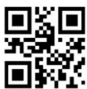
By turning on the setting code function, the parameter setting of the reader can be performed by scanning the setting code.

* On
Off
Output setting code content

* Not

Yes
1.4.2 Factory Default
By scanning the "Factory Default" barcode, all the reader parameters can be restored to the factory configuration.
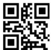
Factory Default
1.4.3 User Default Settings
In addition to the factory settings, the user can also save their frequently used configuration as the default settings of the user, and save the current configuration information of the device as the default setting information of the user by scanning "Save current setting as user default setting". If the reader The user has the default setting information, the new configuration information after the operation will replace the original user default setting information.
By scanning "Restore user default settings" can be changed to the reader user default setting information.

Save current settings as user defaults
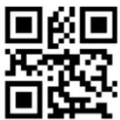
Restore user default settings
2 Interface
HBCS2D100U reader provides TTL-232 serial communication interface to communicate with the host. Through the communication interface, you can receive the read data, send commands to the reader to control, and change the reader's function parameters.
2.1 RS232 Communication Interface
Serial communication interface is a common way to connect the reader with the host device (such as PC, POS, etc.). When the reader and the host using a serial cable connection, the system uses serial communication mode by default. The use of serial communication interface, the reader and the host device must be in the communication parameters on the configuration to match, in order to ensure smooth communication and content is correct.

Serial output
The reader's serial communication interface uses the TTL-level signal (TTL-232), which adapts to most system architectures. If the system requires the use of RS-232 form of the structure, the need to increase the external conversion circuit.
The default serial communication parameters of the reader are shown in Table 2-1. Among them, the baud rate of the reader can be modified through the serial port command, but the remaining parameters can not be modified.
Form 2-1 Default serial communication parameters
| Parameter | Default |
| Serial communication type | Standard TTL-232 |
| Baud rate | 9600 |
| Check | Not |
| Data bit | 8 |
| Stop bit | 1 |
| Hardware flow control | Not |
Baud rate setting

1200bps

4800bps

* 9600bps

14400bps

19200bps

38400bps

57600bps

115200bps
2.1.1 RS232 bit configuration
Customers can modify the serial parity by scanning the following configuration code.

* NONE

ODD

EVEN
2.1.2 RS232 and full-code open quick configuration
In order to help customers quickly configure the serial port and full-code open mode during secondary development, quick configuration function can be realized by scanning the following configuration codes.

Serial & Full open
2.2 USB HID Interface
When the reader module is connected to the host using a USB cable, the reader module can be configured as a HID device by scanning the following setup code.

USB HID device
When the device is used as a HID device, it can be 2 different devices. Configure the following settings.


2.2.1 HID parameter configuration
You can also modify the PC's access cycle to the HID device by scanning the following setup code.

* 1ms

3ms

5ms

10ms
You can also modify the interval between valid message and release message of the device by scanning the following setting codes.

* 0ms

1ms

5ms

10ms

15ms
You can also modify the interval between the device to release the packet and the next valid packet by scanning the following setting code.
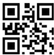
0ms

* 1ms

5ms
10ms

15ms
You can also modify the status of the CapsLock on output by scanning the following setup code.

* Off

On
2.2.2 HID leading key output
Users can scan the following configuration code to output a preamble message before outputting each piece of data from HID, which is convenient for customer software development and positioning.
The key value is ctrl+shift+r

HID disable

HID enable
2.2.3 HID KBW and RS232 output
The user can scan the following configuration code to enable data output through the serial port while HIDKBW is output.

Disable

Enable
2.3 USB-COM
When the HBCS2D100U is connected with the host using the USB cable, the module can be configured as a virtual serial port output mode by scanning the USB virtual serial port setting code.

USB-COM
3 Scan mode (reading mode)
3.1 Manual
Manual reading mode is the default reading mode. In this mode, the HBCS2D100U starts reading the code after pressing the trigger key, and stops the reading after the reading code successfully outputs the message or releases the trigger key.

* Manual
In this mode, HBCS2D100U default idle for a certain period of time, automatically enter the deep sleep mode, can be set by the following setup code.
Sleep time On

* Sleep time OFF
After entering sleep mode, wake up by pressing the key, the device will reboot after exiting sleep mode.
In addition, when deep sleep is not enabled, you can also set the light sleep idle time by scanning the following setting codes.

0ms

* 500ms

3000ms
5000ms
3.2 Successive scanning mode
After setting, without trigger, HBCS2D100U reader immediately start reading, reading code successfully output information or single reading time after the end, HBCS2D100U wait for a period of time (can be set) will automatically start the next reading. If the following conditions do not occur, HBCS2D100U reader will work in the above cycle: During reading the user can also click the trigger button to manually pause the reading. Click the trigger button HBCS2D100U will continue to cycle reading.
Successive Scanning mode
Single reading time
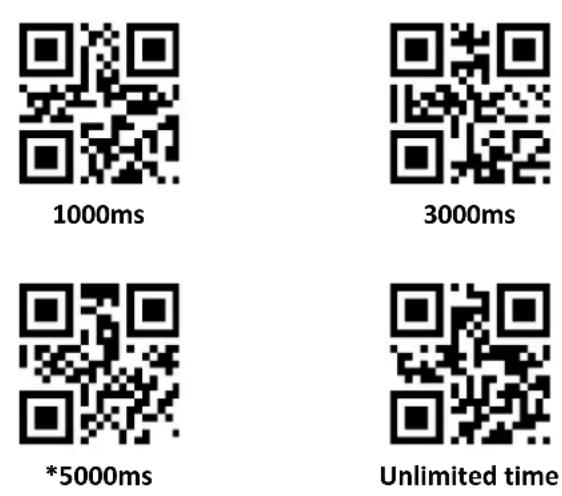
In continuous reading mode, this parameter refers to the reading before the success of HBCS2D100U reader to allow continued recognition of the maximum acquisition time. After a successful reading or a single reading time-out, the HBCS2D100U reader enters the interval of not acquiring readings. Single reading time length setting range of 0.1 \~ 25.5 seconds, step 0.1 seconds; when set to 0, said the reading time unlimited. The default duration is 5.0 seconds.

1000ms

3000ms

* 5000ms

Unlimited time
Reading interval length
This parameter refers to the interval between two adjacent readings, that is, after finishing the last reading of the reader (no matter the reading is successful or not), the reading will not be carried out within the set interval, until the interval ends After reading the next code. The reading interval setting range is from 0 to 25.5 seconds in 0.1 second steps. The default interval is 1.0 second.

No gap

500ms

* 1000ms

1500ms

2000ms
The same bar code reading delay
in order to prevent the same code from being read multiple times in succession, the reader can be asked to read the same code if it can not read the same code continuously for a period of time in this mode.
The same barcode reading delay means that the reader will read the same barcode and compare with the last reading time. When the interval time is longer than the reading delay time, the same barcode is allowed to be read out, otherwise the output is not allowed.

The same bar code reading delay

* The same bar code reading is not extended
The same barcode reading delay time
After enabling the same barcode reading delay, the same barcode reading delay time can be set through the following setting codes
Unlimited delay

500ms

1000ms

3000ms
5000ms
3.3 Autosensing Mode
After setting, without trigger, the reader immediately began to monitor the brightness of the surrounding environment, when the scene changes, the reader waits for the set of image stabilization time after the end of reading. After reading the successful output of information or single reading time-out after the reader to be some time interval (can be set) to re-enter the monitoring state. If the following conditions do not occur, the reader will cycle in the above way: In a single reading time bar code is not scanned, the reader will automatically pause reading and into the monitoring state. In the inductive reading mode, the reader can also start reading the code after pressing the trigger key, and continue to monitor the brightness of the surrounding environment when the reading code successfully outputs the message or release the trigger key.

Autosensing mode
Single reading time
In inductive reading mode, this parameter refers to the maximum length of time that the reader will be allowed to continue acquisition recognition before the reading is successful. After a successful reading or a single reading timeout, the reader will enter the interval of not acquiring readings.
Single reading time length setting range of 0.1 \~ 25.5 seconds, step 0.1 seconds. When set to 0, the reading time is infinite. The default duration is 5.0 seconds.
Reading interval length
After reading the successful output of information or single reading time-out, the reader needs to be some time (can be set) to re-enter the monitoring state. The reading interval setting range is from 0 to 25.5 seconds in 0.1 second steps. The default interval is 1.0 second.

No interval
500ms

* 1000ms

1500ms

2000ms
Stable time
Stabilization time length refers to the sensor reading mode, detect the scene changes in the reader before reading the picture need to wait for the image stabilization time. Stabilization duration is set from 0 to 25.5 seconds in 0.1 second steps. The default image duration is 0.4 seconds.

100ms

*400ms

1000ms

2000ms
Sensitivity
Sensitivity refers to the degree of change of the scene detected in the sense reading mode. When the reader to determine the degree of change in the scene to meet the requirements, will switch from monitoring status to read status.

* Normal sensitivity

Low Sensitivity

High sensitivity

Very high sensitivity
The same bar code reading delay
It is not avoided that the same code is read consecutively multiple times, and the reader may be required to read the same code if it can not read the same code continuously for a period of time in this mode. Set code and continuous mode the same.
3.4 Command Trigger mode
In this mode, the reader starts to read the code when it receives the scan command sent by the host (ie bit0 of flag 0x0002 is written to "1"), and stops reading after the reading succeeds in outputting the message or the reading time of single reading.

Command trigger mode
Note: In the command triggering mode, the serial port triggering the scan command is: 7E 00 08 01 00 02 01 AB CD; Upon receiving the trigger command, the reader will output seven bytes of response message and start the scan synchronously Information content: 02 00 00 01 00 33 31).
Single reading time
In command triggered reading mode, this parameter refers to the maximum length of time that the reader is allowed to continue acquisition recognition before the reading is successful. Single reading time length setting range of 0.1 \~ 25.5 seconds, step 0.1 seconds. When set to 0, the reading time is infinite. The default duration is 5.0 seconds.
1000ms

3000ms

* 5000ms

Infinitely long
3.5 POS mode
The user can quickly configure the module to work in the POS mode by scanning the following setting code, including the following main features:
1: Read mode is command trigger mode;
2: The communication interface is RS232;
3: Turn off the start tone;
4: Close the end terminator;

POS Mode
4 Reading area
For different applications, users need to identify the area there will be some differences, by scanning the following setting code can be set.
4.1 Full area
When the reading area is full area, the reader will scan the barcode with the center as the priority, and the barcode may be anywhere on the screen.

* Full area
4.2 Only the center area
When the reading area is the center area, the center position of the barcode must be within the set center area, and the bar codes that are not in the area are not recognized and output.

Only the center area
Set the center area size
The center area is an area centered on the whole image center. The size of the area is set in proportion to the width or height of the entire image, ranging from 1 to 100. If the setting value is 20, that is, Located in a center area of 20% of the width of a 20% height area.
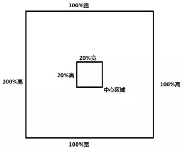
Commonly used center area size can be set by scanning the following setting code:

Center area -20%

Center area -40%
Center area -60%
When the size of the commonly used central area does not meet the needs, the user can also customize the configuration by scanning the "edit center area size" setting code.

Modify the center area size
Example: modify the 50% center area size
- Check the character table to get "50" four characters hexadecimal value: "32"
- Check whether the setting code is on. If it is not on, please scan the setting code "on" (see section 1.5.2)
- Scan "Modify center area size" setting code
- Scan the data setting code "3", "2" (see appendix E)
- Scan "save" setting code (see Appendix F)
5 Lighting and Aiming
5.1 Lingting
Lighting for shooting photography to provide auxiliary lighting, beam exposure to the reading target, to improve reading performance and adaptability to weak ambient light. The user can set it to one of the following depending on the application environment:
Normal (default setting): The light is on when taking a picture, and off at other times.
Always: The light is on after the module is switched on.
No lighting : The lighting does not illuminate under any circumstances.

*Normal

Always

No lighting
5.2 Aiming
The aiming beam projected by the HBCS2D100U helps you find the best reading distance while shooting. Users can choose any of the following modes depending on the application environment.
Normal (default setting): The reader projects the aiming beam only during photographing.
Steady on: After the reader is powered on, it continuously projects the aiming beam.
None Aiming: In any case, the aiming beam is extinguished.

* Normal

Steady on

None Aiming
6 Prompt output
6.1 All beeps
Reading "Buzzer Drive Frequency" sets the buzzer to active / passive buzzer, and also sets the drive frequency of passive buzzer.

Buzzer drive frequency - passive low frequency
Buzzer drive frequency - passive IF

Buzzer drive frequency - passive high frequency

Buzzer drive frequency - active drive
In active buzzer mode, reading "buzzer working level - high" can be set as buzzer idle low level, working high level; buzzer working level - low "can be set as buzzer Idle idle high, working low.

* Buzzer working level - High

Buzzer working level - Low
Read "Start Mute" to turn off all beeps. Read "Turn off mute" to cancel the mute setting.
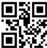
On
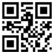
*Off
6.2 Read the success tone
Read the "turn off decoding success tone" can prohibit barcode reading successful voice prompts, read "open the decoding success tone" to restore the barcode reading success prompts.

*Turn on reading success tone

Turn off reading success
tone
Reading the Tone Duration sets the duration for reading the success tone. Default 60ms

Prompt tone duration - 30ms
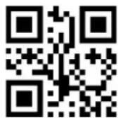
*Prompt tone duration - 60ms

Prompt tone duration - 90ms

Prompt tone duration - 120ms
6.3 Data encoding format
In order for the reader to read Chinese bar codes of various encoding formats, it can be set by reading the "Input Data Encoding Format".
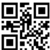
* Input data encoding format GBK

Input data encoding format
UTF8

Input data encoding format AUTO
In order for the host computer to print Chinese data in the specified encoding format, it can be set by reading "Output Data Encoding Format".
Note: GBK format can be used for Notepad, UNICODE format can be used for WORD and common chat tool input box.

* Output data encoding format GBK

Output data encoding format UNICODE

Output data encoding format UTF8
6.4 National keyboard settings
In order for the hosts in all countries to use the device, they can be set by reading the "keyboard" of the corresponding country.
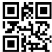
* Keyboard - United States

Czech Republic

France

German

Hungary

Italy

Japan

Spain

Turkey

Tukry Q
6.5 Virtual Keyboard Enable
In order to be able to use more areas, we also provide a virtual keyboard function, enable the virtual keyboard, you can output in any keyboard mode, but the relative loss of a certain output efficiency. Also, when using a virtual keyboard, you must make sure the keypad numeric keys are enabled. Note that the virtual keyboard must be available in versions 1.21 and later.

* Standard keyboard
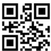
Virtual keyboard
6.6 Invoice mode is enabled
In order to use this module normally in the billing system, the user can convert the format of the invoice code and output it by scanning the following configuration codes.

* Invoice mode is disabled

Invoice mode is enabled
6.7 Image flip
In practice, we encounter a mirror image or vertical flip image, as shown below.


When the bar code appears flip, you can enter the mirror flip mode by scanning the corresponding setting code.
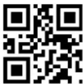
Mirror flip mode ON

Mirror flip mode OFF
Note: In Mirror Flip mode, only the mirror with inverted image can be identified. If you need to identify the normal barcode or setup code, please exit Mirror Flip mode first.
6.8 Black and white flip
In some special scenes, the black and white of the barcode may be reversed. By scanning the following setting codes, the module can be configured to recognize both normal and anti-colored barcodes.

* One-dimensional bar code can disable anti-color decoding

One-dimensional bar codes enable inverse color decoding

* Two-dimensional bar code can disable anti-color decoding

One-dimensional bar codes enable inverse color decoding
6.9 Read the Version Information
In order for the host to quickly read the current version of the device information, you can "read version information" to confirm.
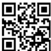
The code of reading the version information
6.10 Reading unique ID of device
In order to obtain the device's unique ID, you can confirm it with the "Read Device Unique ID" barcode.

Read device unique ID
7 Data editing
In practice, sometimes we need to edit the data after reading and then output, to facilitate data differentiation and processing.
Data editing includes:
- Increase Prefix
- Increase Suffix
● Decoding information Data section interception - Output barcode type CodeID
● Decoding failed to output specific RF - Increase the terminal Tail
The processed data default output sequence is as follows:
[Prefix] [CodeID] [Data] [Suffix] [Tail]
7.1 Prefix
Increase the Prefix
The prefix is a string that is customized and modified by the user before decoding information. It can be added by scanning the "Add prefix" setting code.

Allow to increase prefix

Not allow to increase prefix
Modify the prefix
Scan "modify prefix" setting code, and combine scan data setting code, users can modify the prefix content, use two hexadecimal values for each prefix character, the prefix allows up to 15 characters, hexadecimal conversion table of character value Please refer to Appendix D. Scan "modify prefix" setting code, and combine scan data setting code, users can modify the prefix content, use two hexadecimal values for each prefix character, the prefix allows up to 15 characters, hexadecimal conversion table of character value Please refer to Appendix D.

Modify the code
Example: Modify user-defined prefix "DATA"
- Check the character table to get "DATA" four characters hexadecimal value: "44", "41", "54", "41"
- Check whether the setting code is on. If it is not on, please scan the setting code "On" (see section 1.5.2)
- Scan the "Modify prefix" setting code
- Scan the data setting codes "4", "4", "4", "1", "5", "4", "4", "1"
- Scan "Save" setting code
7.2 Suffix
Add a suffix
The suffix is a string that is customized and modified by the user after the information is decoded, and can be added by scanning the "allow suffix" setting code
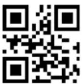
Allow to add a suffix

* Not allow to add a suffix
Modify the suffix
Scan the "Modify Suffix" setting code, and set the scan data setting code, the user can modify the suffix content, use two hexadecimal values for each suffix character, suffix up to 15 characters, character value hexadecimal conversion table Please refer to Appendix D.

Modify the suffix
Example: Modify user-defined suffix "DATA"
- Check the character table to get "DATA" four characters hexadecimal value: "44", "41", "54", "41"
- Check whether the setting code is on. If it is not on, please scan the setting code "On" (see section 1.5.2)
- Scan the "Modify Suffix" setting code
- Scan the data setting codes "4", "4", "4", "1", "5", "4", "4", "1"
- Scan "Save" setting code
7.3 CODE ID
Add CODE ID
Users can use CODE ID to identify different barcode types. The CODE ID corresponding to each barcode type can be freely modified. The CODE ID is identified by a single character.

Allow to add CODE ID

* Not allow to add CODE ID
CODE ID default value
Scan the "CODE ID default" setting code, each bar code corresponding to the CODE ID can be restored to the default value, the default CODE ID can refer to Appendix C

The default CODE ID for all bar codes
Modify the CODE ID
the CODE ID corresponding to each barcode can be freely modified by scanning the corresponding setting code and combining the scan data setting code. CODE ID characters corresponding to each bar code using a hexadecimal value that the character value of the hexadecimal conversion table can refer to Appendix D.
Example: CODE 128 code corresponding to modify the CODE ID "A"
- Check the character table to get the "A" character hexadecimal value: "41"
- Check whether the setting code is on. If it is not on, please scan the setting code "On" (see section 1.5.2)
- Scan the "Change CODE ID of CODE 128" setting code
- Scan the data setting code "4", "1"
- Scan "Save" setting code
Modify each barcode type CODE ID setting code list:
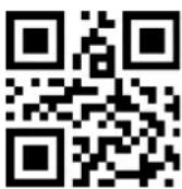
Modify the CODE ID of EAN13

EAN8's CODE ID

Modify UPCA's CODE ID

UPCEO CODE ID

Modify UPCE1's CODE ID

Change Code 128 Code ID

CODE 39 CODE ID

CODE 93 CODE ID

Change CODE ID of CODE
BAR

Change the CODE ID for Interleaved 2 of 5

Modify Industrial 25 CODE
ID

Modify the Matrix 2 of 5
CODE ID

Change CODE 11 CODE ID

MSI CODE ID

Modify the RSS CODE ID

Modify the CODE ID for the restricted RSS

Modify the extended RSS
CODE ID

Modify QR CODE's CODE ID

Modify the Data Matrix
CODE ID

Modify the CODE ID of the Limited PDF417
7.4 Terminator
To enable the host to quickly distinguish between the results of the current decoding, you can turn this feature on.
Read "add terminator" When this function is enabled, if the reading is successful, the reader adds the corresponding terminator after decoding the data

Close the ending character

* Add terminator CR

Increase the ending character TAB
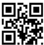
Add terminator CRLF
7.5 Data section interception
When users only need to output part of the decoding information, you can turn on this feature.
We will decode the information [Data] is divided into three parts:
[Start] [Center] [End]
The Start, End section of the character length can be controlled by scanning code.
The user sets the code by scanning the code below, you can choose to output the corresponding position of the decoding information.

*Transfer the entire Data section
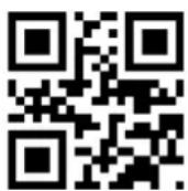
Only the Start segment is transmitted

Only the End segment is transmitted

Only the center segment is transmitted
Modify the length of the Start section M
The length of the Start section can be modified by scanning the "Intercepting length before modification" M and setting the length of the Start section. The maximum length of the Start section is 255 characters. The length of the front section M is represented by a hexadecimal character, and the length M is ten Refer to Appendix D for hex value conversion table.
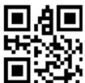
Modify the length of the Start section M
Modify the length of End section N
Scan the "modified interception length N", and set the scan data setting code, you can modify the length of the End section, End section allows up to 255 characters, the interception length N using a hexadecimal character, the length N corresponding to ten Refer to Appendix D for hex value conversion table.
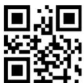
Modify the length of End section N
Only the Start segment is transmitted
Example: When the decoding information is "1234567890123ABC", the first 13 bytes "1234567890123"
- Check the character table to get the decimal data "13" corresponds to the hexadecimal character "0D"
- Check whether the setting code is on. If it is not on, please scan the setting code "on" (see section 1.5.2)
- Scan the "Pre-modification length M" setting code
- Scan the data setting code "0", "D"
- Scan "Save" setting code
- Scan the "Start only transfer" setting code
Only the End segment is transmitted
Example: When the decoding information is "1234567890123ABC", the last three bytes "ABC"
- Check the character table to get the decimal data "3" corresponds to the hexadecimal character "03"
-
Check whether the setting code is on. If it is not on, please scan the setting code "on" (see section 1.5.2)
-
Scan "Modified cut length N" setting code
-
Scan data setting code "0", "3"
-
Scan "Save" setting code
-
Scan "End segment only" setting code
Only the Center section is transmitted
Example: When the decoding information is "12345678900123ABC", the middle four bytes "0123"
- Check the character table to get the decimal data "10", "3" corresponds to the hexadecimal characters were "0A", "03"
- Check whether the setting code is on. If it is not on, please scan the setting code "On" (see section 1.5.2)
- Scan "Modified cut length N" setting code
- Scan data setting code "0", "3"
- Scan "Save" setting code
- Scan "Modify before cut length M" setting code
- Scan the data setting code "0", "A"
- Scan the "Save" setting code
- Scan the "Center section only" setting code
7.6 RF information
RF (Read Fail) message refers to the reader in some modes, you want to read the code is unsuccessful, the user output some information freely defined, the user or program detects this information and make the appropriate adjustments or operations.

Send RF information
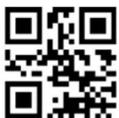
* Not send RF information
Modify RF information
Scan the "Modify RF Information" setting code, and combine the scan data setting code. The user can modify the RF information content, use two hexadecimal values for each RF character, RF up to 15 characters, hexadecimal Conversion table can refer to the appendix.
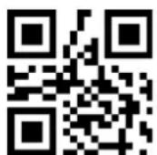
Modify RF information
Example: Modify User Defined RF Information to "FAIL"
- Check the character table to get "FAIL" four characters hexadecimal value: "46", "41", "49", "4C"
- Check whether the setting code is on. If it is not on, please scan the setting code "on" (see section 1.5.2)
- Scan "modify RF information" setting code
- Scan the data setting codes "4", "6", "4", "1", "4", "9", "4", "C"
- Scan "Save" setting code
7.7 Output protocol
The following setting code can be used to modify the output format of the decoding result in serial / virtual serial port mode by scanning.
The format of the output with protocol is selected as follows: <03>
In addition, when the output with protocol is enabled in serial / virtual serial port mode, the module will not add an ending character to the decoded data.

* Pure data

With agreement
7.8 UPCA convert to to EAN 13
You can enable or disable UPCA conversion to EAN13 by scanning the following setting code.
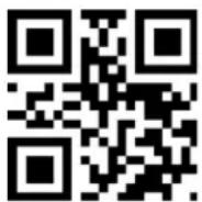
Enable

Disable
7.9 Product code verification output enable
The output of the product code parity bit (including EAN8/EAN13/UPCE0/UPCE1/UPCA) can be enabled by scanning the following setting code.

Enable

Disable
8 Barcode type enable / disable configuration
8.1 All bar codes are solvable
Read the following setting code, all supported bar code types will be allowed or not to be read. After all types are forbidden, only setting code can be read.

All types are allowed to be read

Prohibition of reading all types
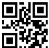
* Open the default type of reading
8.2 Readability
By enabling the bar code reading capability enhancement, the reading angle of all bar codes will be improved, the device's support for angles above 45^ will be improved, and the support for low contrast and gradient codes will be improved. Forbidding angle enhancement will increase decoding speed.

* Disable

Enable
8.3 EAN13
Read the following setting code, will EAN13 bar code to allow / prohibit reading set.

* Allow to read EAN13

Not allow to read EAN13
Read the following setting code, you can configure EAN13 additional code reading is enabled or disabled.

* 2 additional code can be disabled

2 additional code can be enabled

* 5 additional code can be disabled

5 additional code can be enabled
8.4 EAN8
Read the following setting code, will be EAN8 bar code to allow / prohibit read set.
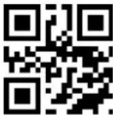
* Allow to read EAN8
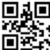
Prohibition of reading EAN8
Read the following setting code, you can configure EAN13 additional code reading is enabled or disabled.

* 2 additional code can be
disabled

2 additional code can be enabled

* 5 additional code can be disabled

5 additional code can be enabled
8.5 UPCA
Read the following setting code to set UPCA bar code enable / disable reading.

* Allow to read UPCA

Not allow to read UPCA
Read the following setting code, you can configure the UPCA additional code reading is enabled or disabled.

* 2 additional code can be disabled

2 additional code is enable

* 5 additional code can be disabled

5 additional code is enabled
8.6 UPCE0
Read the following setting code, set UPCEO bar code enable / disable reading.

* Allow to read UPCEO

Not allow to read UPCEO
8.7 UPCE1
Read the following setting code, set UPCE1 bar code to enable / disable reading.

* Allow to read UPCE1

Not allow to read UPCE1
Read the following setting code, you can configure UPC-E1 additional code reading is enabled or disabled.
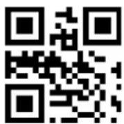
* 2 additional code can be disabled

2 additional code is enabled

* 5-digit additional code can be disabled

5 additional code is enabled
8.8 Code128
Read the following setting code, Code128 bar code to enable / disable the reading to be set.

* Allow to read Code128

Not allow to read Code128
Read the following setting code, will be the shortest reading length of Code128 bar code set.
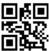
The minimum length of Code128 information is 0

* The minimum length of code is 4
Read the following setting code, the maximum length of Code128 bar code to read set.

* The maximum length of Code128 information is 32
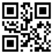
The maximum length of Code128 information is 255
8.9 Code39
Read the following setting code, Code39 bar code to enable / disable the reading to be set.
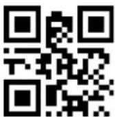
* Allow to read Code39

Not allow to read Code39
Read the following setting code, Code39 bar code will be the shortest length of reading set.

Code39 minimum length of information is 0

* Code39 minimum length of information is 4
Read the following setting code, will set the longest reading length of Code39 bar code.

* Code39 maximum length of 32

Code39 maximum length of information is 255
Read the following setting code, you can configure Code39 whether to support Code32 mode and FullAsc mode.
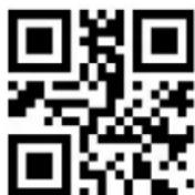
* Code32 is not enabled
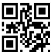
Enable Code32

* Does not enable FullAsc mode

Enable FullAsc mode
8.10 Code93
Read the following setting code, will Code93 bar code to allow / prohibit reading set.

* Allow to read Code93
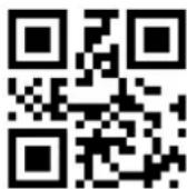
Not allow to read Code93
Read the following setting code, the Code93 bar code will be the shortest length of reading set.

Code93 minimum length is 0

* Code93 minimum length is 4
Code93 bar code will be the longest length of reading set.

* Code93 maximum length is 32

Code93 maximum length is 255
8.11 CodeBar
Read the following setting code, CodeBar bar code to enable / disable the reading set.

* Allow to read CodeBar

Not allow to read CodeBar
Read the following setting code, the CodeBar bar code to allow / prohibit to send start and stop set.

Send CodeBar start and end

* Does not send CodeBar start and end breaks
Read the following setting code, set the minimum length of CodeBar reader.

The minimum length of CodeBar information is 0

* The minimum length of CodeBar information is 4
Read the following setting code, will set the maximum length of CodeBar barcode reader.

* The maximum length of CodeBar information is 32

The maximum length of a CodeBar message is 255
8.12 QR
Read the following setting code, will be set to enable / disable QR barcode reading.

* Allow to read QR

Not allow to read QR
8.13 Interleaved 2 of 5
Read the following setting codes to set the Interleaved 2 of 5 bar code enable / disable reading.

Interleaved 2 of 5 is allowed

* Prohibition of reading Interleaved 2 of 5
Read the following setting code, will set the minimum reading length of Interleaved 2 of 5 bar code.
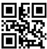
Interleaved 2 of 5 minimum message length is 0

* Interleaved 2 of 5 minimum length is 4
The following setting codes will be read to set the maximum reading length of Interleaved 2 of 5 barcode.

* Interleaved 2 of 5 max message length is 32

Interleaved 2 of 5 maximum message length is 255
8.14 Industrial 25
The following setting codes will be read to set the Enable / Disable for Industrial 25 bar code reading.

Allow to read Industrial 25

* Not allow to read Industrial 25
Read the following setting code, the Industrial 25 bar code to read the shortest length set.

Industrial 25 minimum length is 0

* Industrial 25 minimum length is 4
The following setting codes will be read, and the longest reading length of Industrial 25 bar code will be set.

* The maximum length of the information is 32

The maximum length of the information is 255
8.15 Matrix 2 of 5
Read the following setting codes to set the Matrix 2 of 5 bar code enable / disable reading.

Allow to read Matrix 2 of 5

* Not allow to read Matrix 2 of 5
Read the following setting codes to set the minimum reading length of Matrix 2 of 5 barcode.
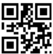
The minimum length is 0

* The minimum length is 4
The following setting codes will be read to set the maximum reading length of Matrix 2 of 5 barcode.

* The maximum length is 32

The maximum length is 255
Read the following setting code, will set the Matrix2 of 5 bar code format.

Parity format is Mod10

* Parity format is None
8.16 Code11
Read the following setting code, will Code11 bar code to allow / prohibit reading set.

Allow to read Code11

*Not allow to read Code11
Read the following setting code, the shortest length of Code11 bar code will be set.

Code 11 minimum length of information is 0
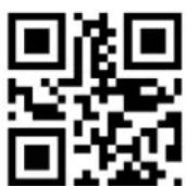
*Code 11 minimum length of information is 4
Read the following setting code, set the maximum length of Code11 barcode reader.

* Code11 maximum length of 32

Code11 maximum length of 255
Read the following setting code, the Code11 calibration method will be configured.

Code11 using 1bit calibration

*Code11 using 1bit calibration
8.17 MSI
Read the following setting code, set the MSI bar code enable / disable reading.

Allow to read MSI

*Not allow to read MSI
Read the following setting code, set the minimum reading length of MSI bar code.

The minimum length of MSI information is 0

*The minimum length of MSI information is 4
Read the following setting code, set the longest reading length of MSI barcode.

* The maximum length of MSI information is 32

The maximum length of MSI information is 255
8.18 RSS
Read the following setting code, will be set to enable / disable RSS-14 bar code reading.

Allow to read RSS-14

*RSS-14Prohibition of reading RSS-14
Read the following setting code, will be limited RSS bar code to allow / prohibit reading set.
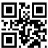
Allow to read RSS

Not allow to read RSS
Read the following setting code, will be extended RSS bar code to allow / prohibit read set.

Allow to read RSS

*Not allow to RSS
Read the following setting code, set the minimum reading length of RSS barcode.

RSS message minimum length is 0

*Minimum length is 4
Read the following setting code, set the maximum length of RSS barcode reader.

* The maximum length of RSS messages is 32

The maximum length of RSS messages is 255
8.19 Data Matrix
Read the following setting code, DM bar code to enable / disable the read set.

*Allow to read DM

Not allow to read DM
Read the following setting code, will set whether the module supports decoding multiple DM barcode at the same time.
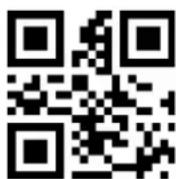
*Do not read more than one DM barcode at the same time

Allows multiple DM bar codes to be read simultaneously
8.20 PDF417
Read the following setting code, will be PDF417 bar code to allow / prohibit read set.

*Allow to read PDF417
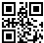
Not allow to read PDF417
9 Appendix A: Default Settings Table
Format 9-1 Default settings table
| parameter name | default setting | Noted | |
| Interface | |||
| TTL-232 | Baud rate | 9600 | |
| Inspection | Not inspection | ||
| Data bit | 8 bits | ||
| Stop bit | 1 bit | ||
| Hardware flow control | Not | ||
| Mode parameters | |||
| The default mode of reading | Manual Mode | ||
| Serial trigger mode | Single reading time | 5s | Parameter range: 0.1-25.5 seconds, step is 0.1s; 0 means that the single decoding time is not limited |
| Manual Mode | Trigger level | Low trigger | The default high level |
10 Appendix B: Common Serial Instructions
Form 10-1 Common serial instructions
| Features | Serial Command |
| Set the baud rate to 9600 | 7E 00 08 01 00 D9 D3 20 38 |
| Save the settings to EEPROM | 7E 00 09 01 00 00 DE C8 |
| Query baud rate | 7E 00 07 01 00 2A 02 D8 0F |
After the host sends the serial port command to query the baud rate, the reading module will reply the following message:
| Returned Messages | Corresponding Baud Rate |
| 02 00 00 02 C4 09 SS SS | 1200 |
| 02 00 00 02 71 02 SS SS | 4800 |
| 02 00 00 02 39 01 SS SS | 9600 |
| 02 00 00 02 D0 00 SS SS | 14400 |
| 02 00 00 02 9C 00 SS SS | 19200 |
| 02 00 00 02 4E 00 SS SS | 38400 |
| 02 00 00 02 34 00 SS SS | 57600 |
Note: SS SS is the calibration value.
11 Appendix C: List of Code IDs
form 11-1 Code ID list
| Type of Bar code | Corresponding character | Flag address |
| EAN-13 | d | 0x91 |
| EAN-8 | d | 0x92 |
| UPC-A | c | 0x93 |
| UPC-E0 | c | 0x94 |
| UPC-E1 | c | 0x95 |
| Code 128 | j | 0x96 |
| Code 39 | b | 0x97 |
| Code 93 | i | 0x98 |
| Codabar | a | 0x99 |
| Interleaved 2 of 5 | e | 0x9A |
| Industrial 2 of 5 | D | 0x9B |
| Matrix 2 of 5 | v | 0x9C |
| Code 11 | H | 0x9D |
| MSI-Plessey | m | 0x9E |
| GS1 Databar(RSS-14) | R | 0x9F |
| GS1 Databar Limited(RSS) | R | 0xA0 |
| GS1 Databar Expanded(RSS) | R | 0xA1 |
| QR Code | Q | 0xA2 |
| Data Matrix | u | 0xA3 |
| PDF 417 | r | 0xA4 |
12 Appendix D: ASCII Code Table
12-1 ASCII code table
| Hexadecimal | Decimal | character |
| 00 | 0 | NUL |
| 01 | 1 | SOH |
| 02 | 2 | STX |
| 03 | 3 | ETX |
| 04 | 4 | EOT |
| 05 | 5 | ENQ |
| 06 | 6 | ACK |
| 07 | 7 | BEL |
| 08 | 8 | BS |
| 09 | 9 | HT |
| 0a | 10 | LF |
| 0b | 11 | VT |
| 0c | 12 | FF |
| 0d | 13 | CR |
| 0e | 14 | SO |
| 0f | 15 | SI |
| 10 | 16 | DLE |
| 11 | 17 | DC1 |
| 12 | 18 | DC2 |
| 13 | 19 | DC3 |
| 14 | 20 | DC4 |
| 15 | 21 | NAK |
| 16 | 22 | SYN |
| 17 | 23 | ETB |
| 18 | 24 | CAN |
| 19 | 25 | EM |
| 1a | 26 | SUB |
| 1b | 27 | ESC |
| 1c | 28 | FS |
| 1d | 29 | GS |
| 1e | 30 | RS |
| 1f | 31 | US |
| 20 | 32 | SP |
| 21 | 33 | ! |
| 22 | 34 | " |
| 23 | 35 | # |
| 24 | 36 | $ |
| 25 | 37 | % |
| 26 | 38 | & |
| 27 | 39 | . |
| 28 | 40 | ( |
| 29 | 41 | ) |
| 2a | 42 | * |
| 2b | 43 | + |
| 2c | 44 | , |
| 2d | 45 | - |
| 2e | 46 | . |
| 2f | 47 | / |
| 30 | 48 | 0 |
| 31 | 49 | 1 |
| 32 | 50 | 2 |
| 33 | 51 | 3 |
| 34 | 52 | 4 |
| 35 | 53 | 5 |
| 36 | 54 | 6 |
| 37 | 55 | 7 |
| 38 | 56 | 8 |
| 39 | 57 | 9 |
| 3a | 58 | : |
| 3b | 59 | ; |
| 3c | 60 | < |
| 3d | 61 | = |
| 3e | 62 | > |
| 3f | 63 | ? |
| 40 | 64 | @ |
| 41 | 65 | A |
| 42 | 66 | B |
| 43 | 67 | C |
| 44 | 68 | D |
| 45 | 69 | E |
| 46 | 70 | F |
| 47 | 71 | G |
| 48 | 72 | H |
| 49 | 73 | I |
| 4a | 74 | J |
| 4b | 75 | K |
| 4c | 76 | L |
| 4d | 77 | M |
| 4e | 78 | N |
| 4f | 79 | O |
| 50 | 80 | P |
| 51 | 81 | Q |
| 52 | 82 | R |
| 53 | 83 | S |
| 54 | 84 | T |
| 55 | 85 | U |
| 56 | 86 | V |
| 57 | 87 | W |
| 58 | 88 | X |
| 59 | 89 | Y |
| 5a | 90 | Z |
| 5b | 91 | [ |
| 5c | 92 | \ |
| 5d | 93 | ] |
| 5e | 94 | ^ |
| 5f | 95 | - |
| 60 | 96 | ' |
| 61 | 97 | a |
| 62 | 98 | b |
| 63 | 99 | c |
| 64 | 100 | d |
| 65 | 101 | e |
| 66 | 102 | f |
| 67 | 103 | g |
| 68 | 104 | h |
| 69 | 105 | i |
| 6a | 106 | j |
| 6b | 107 | k |
| 6c | 108 | l |
| 6d | 109 | m |
| 6e | 110 | n |
| 6f | 111 | o |
| 70 | 112 | p |
| 71 | 113 | q |
| 72 | 114 | r |
| 73 | 115 | s |
| 74 | 116 | t |
| 75 | 117 | u |
| 76 | 118 | v |
| 77 | 119 | w |
| 78 | 120 | x |
| 79 | 121 | y |
| 7a | 122 | z |
| 7b | 123 | { |
| 7c | 124 | | |
| 7d | 125 | } |
| 7e | 126 | ~ |
| 7f | 127 | DEL |
13 Appendix E: Data Codes
0\~9
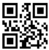
0

1

2

3
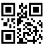
4

5

6

7

8

9
A-F

A

B

C

D

E

F
14 Appendix F: Save or Cancel
After reading the data code to scan the "save" setting code to read the data saved. If you make a mistake while reading the data code, you can cancel reading the wrong data.
Such as reading a setting code and reading the data "A", "B", "C" and "D" in sequence, if "one data before last reading" is read, the last read The number "D" will cancel the read data "ABCD" if "Cancel a previous data string" is read, and cancel the read data "ABCD" if "Unchanged data setting" is read and exit the modification Set.

Save

Cancel the previous read a data

Cancel the previous read a bunch of data

Cancel to change the setting
- LED Devices
- Table of Contents
- Table of Contents....3
- Start 5
- Interface....7
- Scan mode (reading mode).... 12
- Reading area....19
- Lighting and Aiming 21
- Prompt output....22
- Data editing 28
- Barcode type enable / disable configuration.... 36
- Start
- Introduction
- About this Manual
- Barcode reading operation
- Barcode Scanner Settings
- Set Code Switch
- Factory Default
- User Default Settings
- Interface
- RS232 Communication Interface
- RS232 bit configuration
- RS232 and full-code open quick configuration
- USB HID Interface
- HID parameter configuration
- HID leading key output
- HID KBW and RS232 output
- USB-COM
- Scan mode (reading mode)
- Manual
- Successive scanning mode
- Single reading time
- Reading interval length
- The same bar code reading delay
- The same barcode reading delay time
- Autosensing Mode
- Stable time
- Sensitivity
- Command Trigger mode
- POS mode
- Reading area
- Full area
- Only the center area
- Set the center area size
- Example: modify the 50% center area size
- Lighting and Aiming
- Lingting
- Aiming
- Prompt output
- All beeps
- Read the success tone
- Data encoding format
- National keyboard settings
- Virtual Keyboard Enable
- Invoice mode is enabled
- Image flip
- Black and white flip
- Read the Version Information
- Reading unique ID of device
- Data editing
- Prefix
- Increase the Prefix
- Modify the prefix
- Example: Modify user-defined prefix "DATA"
- Suffix
- Add a suffix
- Modify the suffix
- Example: Modify user-defined suffix "DATA"
- CODE ID
- Add CODE ID
- CODE ID default value
- Modify the CODE ID
- Terminator
- Data section interception
- Modify the length of the Start section M
- Modify the length of End section N
- Only the Start segment is transmitted
- Only the End segment is transmitted
- Only the Center section is transmitted
- RF information
- Modify RF information
- Example: Modify User Defined RF Information to "FAIL"
- Output protocol
- UPCA convert to to EAN 13
- Product code verification output enable
- Barcode type enable / disable configuration
- All bar codes are solvable
- Readability
- EAN13
- EAN8
- UPCA
- UPCE0
- UPCE1
- Code128
- Code39
- Code93
- CodeBar
- QR
- Interleaved 2 of 5
- Industrial 25
- Matrix 2 of 5
- Code11
- MSI
- RSS
- Data Matrix
- PDF417
- Appendix A: Default Settings Table
- Appendix B: Common Serial Instructions
- Appendix C: List of Code IDs
- Appendix D: ASCII Code Table
- Appendix E: Data Codes
- Appendix F: Save or Cancel
Brand : Hamlet
Model : HBCS2D100U
Category : Barcode Reader