
Monster Jam - Uncategorized Traxxas - Free user manual and instructions
Find the device manual for free Monster Jam Traxxas in PDF.


| Product Type | 1/10 Scale Remote Control Monster Jam Truck |
| Brand | Traxxas |
| Model | Monster Jam |
| Motor | Titan 12T 550 (Integrated Cooling Fan) |
| Speed Control | XL-5 Electronic Speed Control (Waterproof) |
| Radio System | Traxxas TQ 2-Channel (27 MHz) |
| Battery | 7-Cell NiMH (7.2V) or 2S LiPo (7.4V) with Traxxas High-Current Connector |
| Transmitter Batteries | 8 AA Alkaline or Rechargeable |
| Charger | Includes NiMH charger; optional AC peak-detecting charger (e.g., TRX EZ-Peak) |
| Dimensions (Approx.) | Length: 22 in (560 mm), Width: 18 in (460 mm), Height: 12 in (305 mm) |
| Weight (Approx.) | 5.5 lbs (2.5 kg) with battery |
| Drivetrain | 4WD with Adjustable Slipper Clutch |
| Suspension | Long-Travel with Adjustable Shock Oil, Springs, and Ride Height |
| Water Resistance | Waterproof electronics (ESC, receiver, servos); not submersible |
| Speed Control Profiles | Sport Mode (100% FWD/BRK/REV), Race Mode (100% FWD/BRK, No REV), Training Mode (50% FWD/BRK/REV) |
| Low-Voltage Detection | User-selectable for LiPo (green LED) or NiMH (red LED) |
| Gear Ratio Range | Usable from 12T-35T pinion with 76-90T spur; final ratio = (spur/pinion) x 2.72 |
| Included Optional Gearing | High-speed pinion for hard surfaces (not for off-road) |
| Maintenance | Regular cleaning, lubrication, and inspection of drivetrain, bearings, and motor |
| Safety Features | Thermal shutdown, Throttle Neutral Protection, LiPo low-voltage cutoff |
| Spare Parts Availability | Full support via Traxxas dealers (BuyTraxxas.com) and factory service |
| Manual | 24 pages, free PDF download on notice-facile.com |
Frequently Asked Questions - Monster Jam Traxxas
User questions about Monster Jam Traxxas
0 question about this device. Answer the ones you know or ask your own.
Ask a new question about this device
Download the instructions for your Uncategorized in PDF format for free! Find your manual Monster Jam - Traxxas and take your electronic device back in hand. On this page are published all the documents necessary for the use of your device. Monster Jam by Traxxas.
USER MANUAL Monster Jam Traxxas
TRAYAS
OWNER'S MANUAL
INTRODUCTION
3 BEFORE YOU PROCEED
3 SAFETY PRECAUTIONS
5 TOOLS, SUPPLIES AND REQUIRED EQUIPMENT
6 ANATOMY OF THE MODEL
7 QUICK START: GETTING UP TO SPEED
8 THE TRAXXAS
TQ RADIO SYSTEM
14 ADJUSTING THE ELECTRONIC SPEED CONTROL
16 DRIVING YOUR MODEL
19 ADJUSTING YOUR MODEL
21 MAINTAINING YOUR MODEL
Thank you for purchasing a Traxxas Monster Jam ^® high-performance radio controlled model. With a powerful Titan ^® 12T 550 motor, waterproof electronics, and long-travel suspension, Traxxas Monster Jam models are built for high-speed action and all-terrain fun. The officially-licensed bodies are complimented by authentic wheels and tires with realistic treads molded in a specially formulated rubber compound for long life and superb handling.
This manual contains the instructions you will need to operate, and maintain your model so that you can enjoy it for years to come. We want you to feel confident that you own one of the best-performing models in the market and that it is backed by a team of professionals who aim to provide the highest level of factory support possible. Traxxas models are about experiencing total performance and satisfaction, not just with your model, but also with the company that stands behind it.
We know you're excited about getting your new model on the road, but it's very important that you take some time to read through the Owners Manual. This manual contains all the necessary set-up and operating procedures that allow you to unlock the performance and potential that Traxxas engineers designed into your model. Even if you are an experienced R/C enthusiast, it's important to read and follow the procedures in this manual.
Thank you again for going with Traxxas. We work hard every day to assure you the highest level of customer satisfaction possible. We truly want you to enjoy your new model!
Traxxas Support
Traxxas support is with you every step of the way. Refer to the next page to find out how to contact us and what your support options are.

Quick Start
This manual is designed with a Quick Start path that outlines the necessary procedures to get your model up and running in the shortest time possible. If you are an experienced R/C enthusiast you will find it helpful and fast. Be sure and read through the rest of the manual to learn about important safety, maintenance, and adjustment procedures. Turn to page 7 to begin.
BEFORE YOU PROCEED
Carefully read and follow all instructions in this and any accompanying materials to prevent serious damage to your model. Failure to follow these instructions will be considered abuse and/or neglect.
Before running your model, look over this entire manual and examine the model carefully. If for some reason you decide it is not what you wanted, then do not continue any further. Your hobby dealer absolutely cannot accept a model for return or exchange after it has been run.
WARNINGS, HELPFUL HINTS, & CROSS-REFERENCES Throughout this manual, you'll notice warnings and helpful hints identified by the icons below. Be sure to read them!

An important warning about personal safety or avoiding damage to your model and related components.

Special advice from Traxxas to make things easier and more fun.

Refers you to a page with a related topic.
SUPPORT
If you have any questions about your model or its operation, call the Traxxas Technical Support line toll-free at: 1-888-TRAXXAS (1-888-872-9927)*
Technical support is available Monday through Friday from 8:30am to 9:00pm central time. Technical assistance is also available at Traxxas.com. You may also e-mail customer support with your question at support@Traxxas.com. Join thousands of registered members in our online community at Traxxas.com.
Traxxas offers a full-service, on-site repair facility to handle any of your Traxxas service needs. Maintenance and replacement parts may be purchased directly from Traxxas by phone or online at BuyTraxxas.com. You can save time, along with shipping and handling costs, by purchasing replacement parts from your local dealer.
Do not hesitate to contact us with any of your product support needs. We want you to be thoroughly satisfied with your new model!
SAFETY PRECAUTIONS
All of us at Traxxas want you to safely enjoy your new model. Operate your model sensibly and with care, and it will be exciting, safe, and fun for you and those around you. Failure to operate your model in a safe and responsible manner may result in property damage and serious injury. The precautions outlined in this manual should be strictly followed to help ensure safe operation. You alone must see that the instructions are followed and the precautions are adhered to.
IMPORTANT POINTS TO REMEMBER
- Your model is not intended for use on public roads or congested areas where its operation can conflict with or disrupt pedestrian or vehicular traffic.
- Never, under any circumstances, operate the model in crowds of people. Your model is very fast and could cause injury if allowed to collide with anyone.
- Because your model is controlled by radio, it is subject to radio interference from many sources that are beyond your control. Since radio interference can cause momentary losses of radio control, always allow a safety margin in all directions around the model in order to prevent collisions.
• The motor, battery, and speed control can become hot during use. Be careful to avoid getting burned. - Don't operate your model at night, or anytime your line of sight to the model may be obstructed or impaired in any way.
- Most importantly, use good common sense at all times.
SPEED CONTROL
Your XL-5 is an extremely powerful electronic device capable of delivering high current. Please closely follow these precautions to prevent damage to the speed control or other components.
- 15-Turn Motor Limit: The XL-5 has a 15-turn modified motor limit for 540 size motors and a 12-turn modified motor limit for 550 size motors with 0 timing when the motor is properly geared. If the motor or speed control is overheating, try a smaller pinion gear. Do not attempt to use a more powerful motor (fewer turns) than the above mentioned motor limits or you could experience frequent thermal shutdown.
- Insulate the Wires: Always insulate exposed wiring with heat shrink tubing to prevent short circuits.
- Water and Electronics Do Not Mix: The XL-5 speed control is waterproof for use in mud, snow, puddles, and other wet conditions. Make certain the other components of your model are waterproof or have sufficient water resistance before driving in wet conditions.
Traxxas
1100 Klein Road
Plano, Texas 75074
Phone: 972-265-8000
Toll-free 1-888-TRAXXAS
Internet
Traxxas.com
E-mail: support@Traxxas.com
Entire contents ©2011 Traxxas.
Traxxas, Ready-To-Race,
Ready-To-Win and ProGraphix
are trademarks or registered
trademarks of Traxxas. Other
brand names and marks are
the property of their respective
holders and are used only for
purposes of identification. No
part of this manual may be
reproduced or distributed in print
or electronic media without the
express written permission of
Traxxas. Specifications are subject
to change without notice.


All instructions and precautions outlined in this manual should be strictly followed to ensure safe operation of your model.

This model is not intended for use by children under 14 years of age without the supervision of a responsible and knowledgeable adult.

No previous experience with radio controlled models is required. Models require a minimum of setup, maintenance, or support equipment.
4 • TRAXXAS
SAFETY PRECAUTIONS
- Transmitter on First: Switch on your transmitter first before switching on the speed control to prevent runaways and erratic performance.
- Use Neutrally Timed Motors: For reverse use, the motors must have 0^ timing. Modified motors (with adjustable end bells) timed to 0^ or Johnson/ Mabuchi (closed end bell) motors are recommended. Using motors with other than 0^ timing will draw excess current in reverse, and can result in the speed control overheating and premature motor wear.
- Always Use Heat Sinks: Three heat sinks are factory-installed on the speed control and must be used for maximum cooling and performance.
- 4-8 NiMH cells or 2 LiPo cells (2S) Only: The XL-5 can only accept a maximum input voltage of 9.6 volts (NiMH), 7.4 volts (2S LiPo). Always adhere to the minimum and maximum limitations of the XL-5 as stated in the specifications table.
- Don't Get Burned: The transistor tabs and the heat sinks can get extremely hot, so be careful not to touch them until they cool. Supply adequate airflow for cooling.
- Use Stock Connectors: If you decide to change the battery or motor connectors, only change one battery or motor connector at a time. This will prevent accidentally mis-wiring the speed control. If the XL-5 is not wired exactly as shown in the diagram, it can be damaged! Please note that modified speed controls can be subject to a rewiring fee when returned for service.
- No Reverse Voltage: The speed control is not protected against reverse polarity voltage. When changing the battery and/or motor, be sure to install the same type of connectors to avoid reverse polarity damage to the speed control. Removing the battery connectors on the speed control or using the same-gender connectors on the speed control will void the product's warranty.
- Motor Capacitors Required: Three 0.1 F (50V) ceramic capacitors should be properly installed on every motor to prevent radio interference. Capacitors have been provided with the XL-5.
- Do Not Let the Transistor Tabs Touch: Never allow the three separate transistor banks to touch each other or any exposed metal. This will create a short circuit and damage the speed control.
- No Schottky Diodes: External schottky diodes are not compatible with reversing speed controls. Using a schottky diode with the XL-5 will damage the ESC and void the 30-day warranty.
BATTERIES AND BATTERY CHARGING
The XL-5 speed control uses rechargeable batteries that must be handled with care for safety and long battery life. Make sure to read and follow all instructions and precautions that were provided with your battery packs and your charger. It is your responsibility to charge and care for your battery backs properly. In addition to your battery and charger instructions, here are some more tips to keep in mind.
- Never leave batteries to charge unattended.
- Remove the batteries from the model while charging.
- Allow the battery packs to cool off between runs (before charging).
• Always unplug the battery from the electronic speed control when the model is not in use and when it is being stored or transported. - Do not use battery packs that have been damaged in any way.
- Do not use battery packs that have damaged wiring, exposed wiring, or a damaged connector.
- Children should have responsible adult supervision when charging and handling batteries.
LiPo Batteries
Warning: Lithium Polymer (LiPo) batteries require special care and handling procedures for long life and safe operation. LiPo batteries are intended only for advanced users that are educated on the risks associated with LiPo battery use. Traxxas does not recommend that anyone under the age of 16 use or handle LiPo battery packs without the supervision of a knowledgeable and responsible adult.
The XL-5 speed control is able to use LiPo batteries with nominal voltage not to exceed 7.4 volts (2S packs). LiPo batteries have a minimum safe discharge voltage threshold that should not be exceeded. The XL-5 is equipped with built-in Low-Voltage Detection that alerts the driver when LiPo batteries have reached their minimum voltage (discharge) threshold. It is the driver's responsibility to stop immediately to prevent the battery pack from being discharged below its safe minimum threshold.
Low-Voltage Detection on the speed control is just one part of a comprehensive plan for safe LiPo battery use. It is critical for you, the user, to follow all other instructions supplied by the battery manufacturer and the charger manufacturer for proper charging, use, and storage of LiPo batteries. Make sure you understand how to use your LiPo batteries. Be aware that Traxxas shall not be liable for any special, indirect, incidental, or consequential damages arising out of the installation and/or use of LiPo batteries in Traxxas products.
If you have questions about LiPo battery usage, please consult with your local hobby dealer or contact the battery manufacturer.
TOOLS, SUPPLIES AND REQUIRED EQUIPMENT
Your model comes with a set of specialty metric tools. You'll need to purchase other items, available from your hobby dealer, to operate and maintain your model.
SUPPLIED TOOLS AND EQUIPMENT
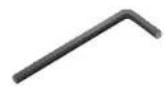
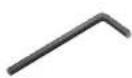
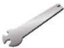
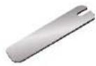
2.0mm "L" wrench 1.5mm "L" wrench
Turnbuckle wrenches
U-joint wrench
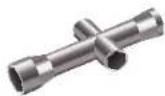
4-way wrench


Optional Pinion Gear see page 20
Aftermarket servo adapters
Various pre-load spacers and shock pistons (on parts tree) see page 19
Battery pad (to reduce battery vibration, if necessary)
Body clips and body washers
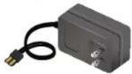
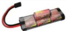
NiMH battery charger*
7-cell NiMH battery pack with Traxxas High-Current Connector*
REQUIRED EQUIPMENT
(SOLD SEPARATELY)

8 AA alkaline batteries
Recycling Your Traxxas Power Cell NiMH Battery
Traxxas strongly encourages you to recycle your Power Cell battery when it has reached the end of its useful life. Do not throw your battery in the trash. All Power Cell battery packs display the RBRC (Rechargeable Battery Recycling Corporation) icon, indicating they are recyclable. To find a recycling center near you, ask your local hobby dealer or visit www.call2recycle.org.
*Battery and charger style are subject to change and may vary from images.

For more information on batteries, see Use the Right Batteries on page 10.

Recommended Equipment These items are not required for the operation of your model, but are a good idea to include in any R/C toolbox: • Safety glasses
- Thin, hobby-quality cyanoacrylate instant tire glue (CA glue)
- Hobby knife
- Side cutters and/or needle nose pliers
- Philips screwdriver
- Soldering iron
6 • TRAXXAS
Colors and appearance may vary from photo depending on your specific Monster Jam ^® model.
QUICK START: GETTING UP TO SPEED

The following guide is an overview of the procedures for getting your model running. Look for the Quick Start logo on the bottom corners of Quick Start pages.

- Read the safety precautions on pages 3-4 7. Check servo operation • See page 13
For your own safety, understand where carelessness and misuse could lead to personal injury.
Make sure the steering servo is working correctly.

- Charge the battery pack · See page 10 8. Range test the radio system · See page 13
Charge your battery now so it will be ready when you finish the other setup procedures.
Follow this procedure to make sure your radio system works properly at a distance and that there is no interference from outside sources.

- Install batteries in the transmitter • See page 10 9. Detail your model • See page 9
The transmitter requires 8 AA alkaline or rechargeable batteries.
Install wings (if necessary) and apply other decals if desired.

- Install battery pack in the model • See page 11 10. Drive your model • See page 16
Your model requires a fully charged 7.2-volt battery pack. Driving tips and adjustments for your model.

- Install the antenna · See page 11 11. Maintaining your model · See page 21
Install the antenna mast in the model. Follow these critical steps to maintain the performance of your model and keep it in excellent running condition.

- Turn on the radio system • See page 13
Make a habit of turning the transmitter on first, and off last.

The Quick Start Guide is not intended to replace the full operating instructions available in this manual. Please read this entire manual for complete instructions on the proper use and maintenance of your model.
Look for the Quick Start logo at the bottom of Quick Start pages.

TRAXXAS
XL-5 Wiring Diagram
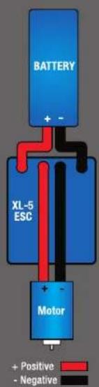
flowchart
graph TD
    A["BATTERY"] -->|+ -| B["XL-5 ESC"]
    B --> C["Motor"]
    C --> D["+ -"]
    style A fill:#333,stroke:#fff,color:#fff
    style B fill:#333,stroke:#fff,color:#fff
    style C fill:#333,stroke:#fff,color:#fff
    style D fill:#fff,stroke:#000,stroke-width:2px
THE TRAXXAS TQ RADIO SYSTEM
Your model is equipped with the Traxxas TQ Radio System. The Traxxas TQ Radio System is a 2-channel system that provides high-power output up to a quarter mile. Your model uses one servo and an electronic speed control.
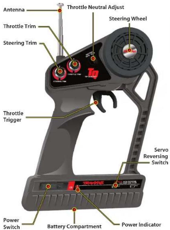
TQ TRANSMITTER
WIRING DIAGRAM
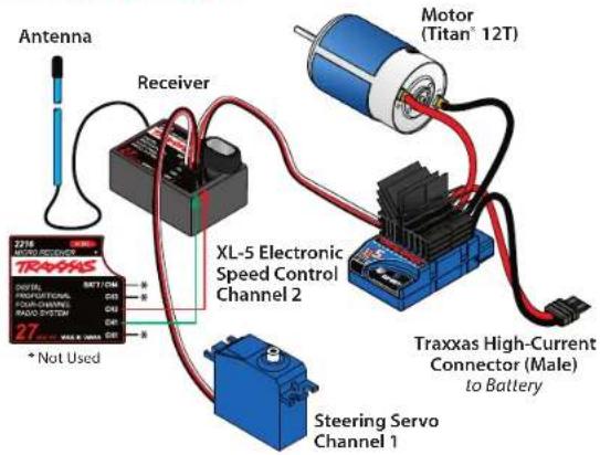
XL-5 ELECTRONIC SPEED CONTROL
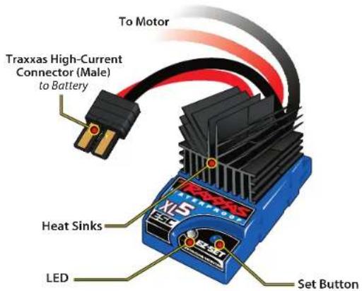
THE TRAXXAS TQ RADIO SYSTEM
RADIO AND POWER SYSTEM TERMINOLOGY
Please take a moment to familiarize yourself with these radio and power system terms. They will be used throughout this manual.
BEC (Battery Eliminator Circuit) - The BEC can either be in the receiver or in the ESC. This circuit allows the receiver and servos to be powered by the main battery pack in an electric model. This eliminates the need to carry a separate pack of 4 AA batteries to power the radio equipment.
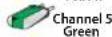
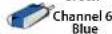
Channel - The 27 MHz frequency band is divided into 6 channels so that up to six models can be operated simultaneously. Each channel is referred to by its flag color and channel number, as shown below.
| CHANNEL | FREQUENCY BAND | FLAG COLOR | TRAXXAS PART NO. |
| 1 | 26.995 BROWN 2031 | ||
| 2 | 27.045 RED 2032 | ||
| 3 | 27.095 ORANGE 2033 | ||
| 4 | 27.145 YELLOW 2034 | ||
| 5 | 27.195 GREEN 2035 | ||
| 6 | 27.255 BLUE 2036 |
Clearing your frequency - A routine, verbal check to make sure nobody else in your area is operating on the same channel. Always clear your frequency by calling out your channel number before operating your model. Wait or move to another area if your channel is already being used.
Crystal (X-tal) - The plug-in device that determines which channel the radio system will operate on. For each channel, there are two crystals, one for the receiver and one for the transmitter. Of those two crystals, the one marked with the lower number (.455 MHz lower) must be inserted into the receiver.
Current - Current is a measure of power flow through the electronics, usually measured in amps. If you look at wire like a garden hose, current is a measure of how much water is flowing through the hose.
ESC (Electronic Speed Control) - An electronic speed control is the electronic motor control inside the model. The XL-5 uses MOSFET power transistors to provide precise, digital proportional throttle control. Electronic speed controls use power more efficiently than mechanical speed controls so that the batteries run longer. An electronic speed control also has circuitry that prevents loss of steering and throttle control as the batteries lose their charge.
Frequency band - The radio frequency used by the transmitter to send signals to your model. All Traxxas RTR models operate on a 27 MHz frequency band.
LiPo - Abbreviation for Lithium Polymer. Rechargeable LiPo battery packs are known for their special chemistry that allows extremely
high energy density and current handling in a compact size. These are high performance batteries that require special care and handling. For advanced users only.
mAh - Abbreviation for milliamp hour. A measure of the capacity of the battery pack. The higher the number, the longer the battery will last between recharges.
Neutral position - The standing position that the servos seek when the transmitter controls are at the neutral setting.
NiCad - Abbreviation for nickel-cadmium. The original rechargeable hobby pack, NiCad batteries have very high current handling, high capacity, and can last up to 1000 charging cycles. Good charging procedures are required to reduce the possibility of developing a "memory" effect and shortened run times.
NiMH - Abbreviation for nickel-metal hydride. Rechargeable NiMH batteries offer high current handling, and much greater resistance to the "memory" effect. NiMH batteries generally allow higher capacity than NiCad batteries. They can last up to 500 charge cycles. A peak charger designed for NiMH batteries is required for optimal performance.
Receiver - The radio unit inside your model that receives signals from the transmitter and relays them to the servos.
Resistance - In an electrical sense, resistance is a measure of how an object resists or obstructs the flow of current through it. When flow is constricted, energy is converted to heat and is lost.
Servo - Small motor unit in your model that operates the steering mechanism.
Transmitter - The hand-held radio unit that sends throttle and steering instructions to your model.
Trim - The fine-tuning adjustment of the neutral position of the servos, made by adjusting the throttle and steering trim sliders on the face of the transmitter.
Thermal Shutdown Protection - Temperature sensing electronics are used in the ESC to detect overloading and overheating of the transistor circuitry. If excessive temperature is detected, the unit automatically shuts down to prevent damage to the electronics.
2-channel radio system - The TQ radio system, consisting of the receiver, the transmitter, and the servos. The system uses two channels: one to operate the throttle and one to operate the steering.
Voltage - Voltage is a measure of the electrical potential difference between two points, such as between the positive battery terminal and ground. Using the analogy of the garden hose, while current is the quantity of water flow in the hose, voltage corresponds to the pressure that is forcing the water through the hose.

Applying The Decals
The main decals for your model have been applied at the factory. The decals are printed on self-adhesive clear mylar and are die-cut for easy removal. Use a hobby knife to lift the corner of a decal and lift it from the backing.
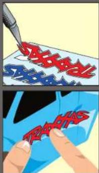
To apply the decals, place one end down, hold the other end up, and gradually smooth the decal down with your finger as you go. This will prevent air bubbles. Placing both ends of the decal down and then trying to smooth it out will result in air pockets.

TRAXXAS • 9
THE TRAXXAS TQ RADIO SYSTEM

The following Traxxas High Current Connector packages are available from your hobby dealer. When using adapters, be careful not to exceed the current rating of the Molex connector.

Part #3060 Single Male/Female


Part #3080 2-Pack Female
Part #3070 2-Pack Male
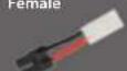
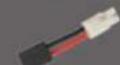
Part #3061 Male Charge Adapter
Part #3062 Female Charge Adapter

Use the Right Batteries Your transmitter uses AA batteries. Use new alkaline batteries, or rechargeable batteries such as NICad or NIMH (Nickel Metal Hydride) batteries in your transmitter. Make sure rechargeable batteries are fully charged according to the manufacturer's instructions.
If you use rechargeable batteries in your transmitter, be aware that when they begin to lose their charge, they lose power more quickly than regular alkaline batteries.
Caution: Discontinue running your model at the first sign of weak batteries (flashing red light) to avoid losing control.

10 • TRAXXAS
INSTALLING TRANSMITTER BATTERIES
Your TQ transmitter uses 8 AA batteries. The battery compartment is located in the base of the transmitter.
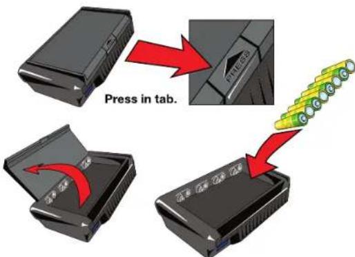
- Remove the battery compartment door by pressing the tab and lifting the door up.
- Install the batteries in the correct orientation as indicated in the battery compartment.
- Reinstall the battery door and snap it closed.
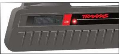
- Turn on the transmitter and check the power indicator for a solid red light.
If the power indicator light flashes, then the transmitter batteries are weak, discharged or possibly installed incorrectly. Replace with new or freshly charged batteries. The power indicator light does not indicate the charge level of the battery pack installed in the model.
CHARGING THE BATTERY PACK
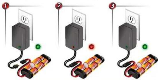
The included charger can be used to charge the included battery pack. The battery pack should be removed from the vehicle before charging. Do not leave the battery unattended while charging. It is normal for the battery to become slightly warm as it nears full-charge, but the battery should never become hot. If the battery becomes hot, disconnect it from the charger immediately. The included charger is not for use with LiPo batteries.
- Plug the charger into the wall. The LED on the charger should glow green.
- Connect the included battery pack to the charger output cord. The LED will glow red indicating the battery is charging.
- The battery should charge for approximately 8 ½ hours. The LED will turn green when the battery is fully charged. Disconnect the battery from the charger after charging.

Using Other Chargers
Another convenient option for charging the included battery is an AC peak-detecting charger that plugs directly into an AC wall outlet, such as the TRX EZ-Peak® (Part #2930). It contains special peak-detection circuitry that automatically shuts the charger off when the battery is fully charged.
For faster charging, the included battery may be charged at 4 amps. The TRX EZ-Peak™ is a 4 amp charger and will charge the included battery in only 45 minutes!
Caution: Never use a 15-minute timed charger to recharge your model's battery packs. Overcharging may result, causing damage to the battery packs.
THE TRAXXAS TQ RADIO SYSTEM
Installing the Battery Pack
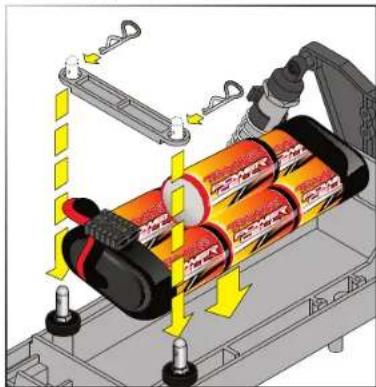
Place the battery pack into the battery compartment of the model and then place the battery hold-down over the posts. Secure the battery hold-down with body clips in the holes in the posts. Do not connect the battery pack yet.
natural_image
Diagram of a battery pack being loaded with a motor, showing internal components and safety mechanisms (no text or symbols)The Traxxas High-Current Connector
Your model is equipped with the Traxxas High-Current Connector. Standard connectors restrict current flow and are not capable of delivering the power needed to maximize the output of the electronic speed control. The Traxxas connector's
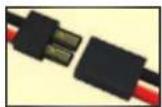
gold-plated terminals with a large contact surfaces ensure positive current flow with the least amount of resistance. Secure, long-lasting, and easy to grip, the Traxxas connector is engineered to extract all the power your battery has to give.
To run this model, your batteries must be equipped with Traxxas High-Current Connectors. Batteries can either be purchased new with Traxxas connectors installed or Traxxas connectors can be purchased to install on battery packs you already own. See sidebar on page 10 for packages available from your hobby dealer.
The typical Molex style connector is inadequate for use in your model. It creates resistance that becomes a bottleneck to current flow. If your battery pack is equipped with a Molex connector, it must be replaced with a Traxxas High-Current Connector to mate with the electronic speed control.
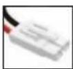
Molex connector
SETTING UP THE ANTENNA
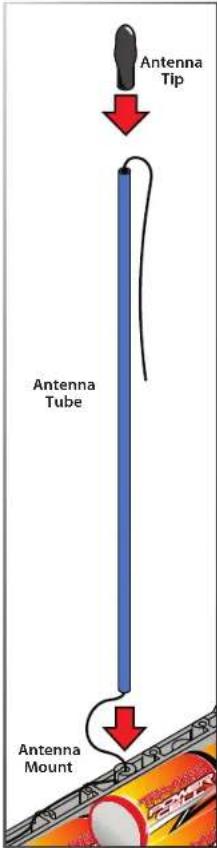
You must install the antenna mast (tube) before you operate your model. You'll find the plastic antenna tube and tip in the bag with your manuals and documentation.
- Locate the black antenna wire that exits the receiver.
- Pull the wire straight with your fingers several times until it is straight (no kinks or bends) and then insert the end of the wire into one end of the antenna tube. Push the wire all the way through the antenna tube.
- Pull the remaining wire through the antenna tube, and then insert the base of the antenna tube into the molded post on the chassis.
- Fold the remaining antenna wire over the top of the tube and secure it with the antenna tip.
- On the transmitter, always fully extend the telescoping antenna when running your model. Make a habit of holding the transmitter so that the antenna points straight up.

If the power indicator doesn't light red, check the polarity of the batteries. Check rechargeable batteries for a full charge.

Spray a little window cleaner on the antenna wire to make it easier to push through the antenna tube.

If there are any kinks in the black antenna wire, it will be more difficult to push through the antenna tube. Pull the wire straight by sandwiching it between your thumb and index finger and running your fingers along the length of the wire (with medium pressure).

Don't shorten the length of the antenna wire. Its length is tuned to the frequency band; cutting it could severely shorten the radio system's range.

Don't push the transmitter antenna down from the top. Pull it down from the bottom, one segment at a time, to prevent binding and kinking the antenna mast.

TRAXXAS • 11
THE TRAXXAS TQ RADIO SYSTEM
TQ RADIO SYSTEM CONTROLS
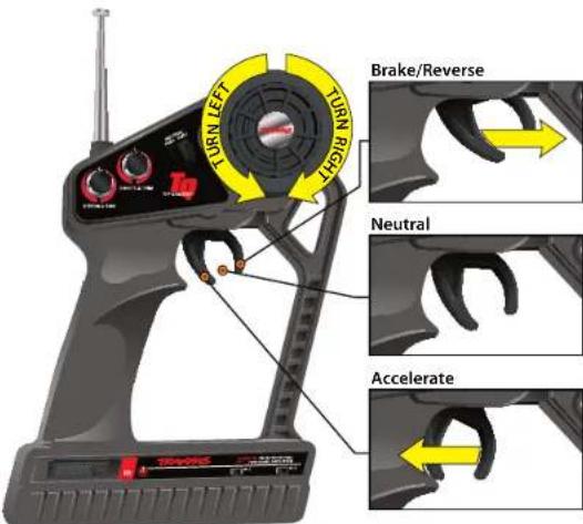
TQ RADIO SYSTEM ADJUSTMENTS
In addition to the electronic throttle and steering trim controls, your radio system features throttle neutral adjustment and servo reversing switches. These are preset at the factory and should not require further adjustment.
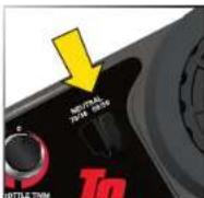
Throttle Neutral Adjustment
The throttle neutral adjustment is located on the transmitter face and controls the forward/reverse travel of the throttle trigger. Change the adjustment by pressing the button and sliding it to the desired position.
There are two settings available:
50/50: Allows equal travel for both acceleration and reverse.
70/30: Allows more throttle travel (70%) and less reverse travel (30%).
Note: If you change throttle travel, you will need to reprogram the electronic speed control.
Electronic Throttle Trim
The electronic throttle trim located on the face of the transmitter adjusts the neutral (center) point of the throttle servo when the servo is at rest. If your model uses an electronic speed control instead of a throttle servo, this control has been preset for you at the factory.
Electronic Steering Trim
The electronic steering trim located on the face of the transmitter adjusts the neutral (center) point of the steering servo when the servo is at rest. Adjust this control to make the model drive straight with no steering input at the wheel.
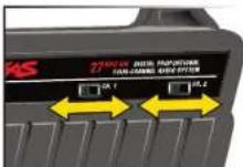
Servo Reversing Switches
The servo reversing switches are located on the front of the transmitter, next to the on/off switch. Moving a switch reverses the direction of the corresponding servo.
Each switch corresponds to a channel, as shown below. For example, if you turn the steering wheel to the right and your wheels turn left, you would move the Channel 1 switch to correct the servo direction. It may be necessary to adjust the corresponding trim control after moving a switch.
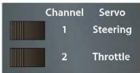
Default Setting
THE TRAXXAS TQ RADIO SYSTEM
TQ RADIO SYSTEM RULES
Each time you prepare to run your model, you must clear your frequency to be sure no one else in the area is using the same channel as you. There are six possible channels, numbered 1 through 6. Each is represented by a color. Look at the crystal plugged into the back of your transmitter to determine which channel your model is assigned to.
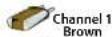
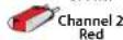
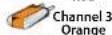
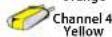
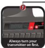
Always turn your TQ transmitter on first and off last. This procedure will help to prevent your model from receiving stray signals from another transmitter, or other source, and running out of control.
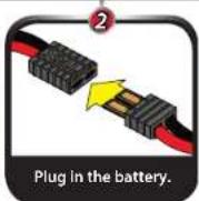
Always have the transmitter turned on before plug in the battery.
Always use new or freshly charged batteries for the radio system. Weak batteries will limit the range of the radio signal between the receiver and the transmitter. Loss of the radio signal can cause you to lose control of your model.
TQ RADIO SYSTEM SETUP
The TQ Radio System was pre-adjusted at the factory. The adjustment should be checked, before running the model, in case of movement during shipping. Here's how:
- Fully extend the chrome antenna mast on the transmitter and turn the switch on. The red indicator light on the transmitter should be solid red (not flashing).
- Elevate the model so that the rear tires are off the ground. If you are holding the model, grip it firmly. Make sure your hands are clear of the moving parts of the model.
-
Plug the battery pack in the model into the speed control.
-
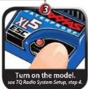
The on/off switch is integrated into the speed control. With the transmitter on, press the XL-5 set button for 12 second, until the LED shines red, then immediately release the button. This turns the model on (see page 14 for more on XL-5 setup and operation). To turn the XL-5 off, press the set button until the red LED turns off.
Note: If the LED shines green, Low-Voltage Detection is activated. This will cause erratic performance from the included NiMH battery pack. The default factory setting is for Low-Voltage Detection to be disabled (LED shines red). Make sure to turn the Low-Voltage Detection on when using LiPo batteries. Never use LiPo batteries while Low-Voltage Detection is turned off. See page 14 for more information.
- Turn the steering wheel on the transmitter back and forth and check for rapid operation of the steering servo. Also, check that the steering mechanism is not loose or binding. If the steering operates slowly, check for weak batteries.
- When looking down at model, the front wheels should be pointing straight ahead. If the wheels are turned slightly to the left or right, slowly adjust the steering trim control on the transmitter until they are pointing straight ahead.
- Operate the throttle trigger to ensure that you have full forward and reverse operation, and that the motor stops when the throttle trigger is at neutral.
- Once adjustments are made, turn off your model, followed by the hand held transmitter.
RANGE-TESTING THE TQ RADIO SYSTEM
Before each running session with your model, you should range-test your radio system to ensure that it operates properly.
- Turn on the radio system and check its operation as described in the previous section.
- Have a friend hold the model. Make sure hands and clothing are clear of the wheels and other moving parts on the model.
- Make sure your transmitter antenna is fully extended, and then walk away from the model with the transmitter until you reach the farthest distance you plan to operate the model.
- Operate the controls on the transmitter once again to be sure that the model responds correctly.
- Do not attempt to operate the model if there is any problem with the radio system or any external interference with your radio signal at your location.

Remember, always turn the TQ transmitter on first and off last to avoid damage to your model.

Your speed control was adjusted to the radio from the factory. It is possible for the throttle trim control on the transmitter to have moved during transit or while handling the transmitter. If the motor runs when the model is switched on, then move the throttle trim control on the transmitter until the motor stops. If anything more than a slight adjustment of the throttle trim control is required, then you should readjust your speed control. Refer to the adjustments section on page 14.

When rechargeable batteries begin to lose their charge, they will fade much faster than alkaline dry cells. Stop immediately at the first sign of weak batteries. Never turn the transmitter off when the battery pack is plugged in. The model could run out of control.

TRAXXAS • 13

XL-5 Specifications
Input Voltage
4-8 cells NiMH; 2S LiPo
Case Size
1.23"W x 2.18"L x 0.61"H
Weight
(2.79 Ounces / 3.03 Ounces)
Motor Limit
15-turns (540 Size) /
12-turns (550 Size)
On Resistance Forward
0.007 Ohms
On Resistance Reverse
0.014 Ohms
Peak Current - Forward
100A
Peak Current - Reverse
60A
Braking Current
60A
Continuous Current
14A
BEC Voltage
6.0 VDC
BEC Current
1A
Power Wire
14 Gauge / 5"
Input Harness Wire
26 Gauge / 9"
Transistor Type
MOSFET
PWM Frequency
1600 Hz
Thermal Protection
Thermal Shutdown
Single Button Setup
Yes
Low-Voltage Detection
Yes (User Enabled)
ADJUSTING THE ELECTRONIC SPEED CONTROL
XL-5 Battery Settings (Low-Voltage Detection Setting)
The XL-5 electronic speed control is equipped with built-in Low-Voltage Detection. The Low-Voltage Detection circuitry constantly monitors the battery voltage. When the battery voltage begins to reach the minimum recommended discharge voltage threshold for LiPo battery packs, the XL-5 will limit the power output to 50% throttle. When the battery voltage attempts to fall below the minimum threshold, the XL-5 will shut down all motor output. The LED on the speed control will slowly blink red, indicating a low-voltage shutdown. The XL-5 will stay in this mode until a fully charged battery is connected.
Your model includes a Power Cell NiMH battery. The XL-5 speed control's Low-Voltage Detection has been disabled for best performance with this battery. The speed control's LED will glow red when it is turned on, indicating Low-Voltage Detection is disabled. Be certain to activate Low-Voltage Detection if you install LiPo batteries in your model. Never use LiPo batteries while Low-Voltage
Detection is disabled.
Verify that Low-Voltage Detection is DISABLED:
-
Turn on the transmitter (with the throttle at neutral).
-
Connect a fully charged battery pack to the XL-5.
-
Press and release the EZ-Set button to turn the XL-5 on. If the LED is solid red, then the Low-Voltage Detection is DISABLED (not safe to use LiPo batteries). If the LED is solid green, then Low-Voltage Detection is ACTIVATED.
To activate Low-Voltage Detection (LiPo setting):
-
Make sure the LED on the XL-5 is on and RED.
-
Press and hold the EZ-Set button (the LED will turn off) (A). After ten seconds, the motor will beep twice and the LED will shine GREEN. Release the button (B).
-
Low-Voltage Detection is now ACTIVATED.
To disable Low-Voltage Detection (NiMH setting):
-
Make sure the LED on the XL-5 is on and GREEN.
-
Press and hold the EZ-Set button (the LED will turn off) (A). After ten seconds, the motor will beep three times and the LED will shine RED. Release the button (B).
-
Low-Voltage Detection is now DISABLED.
Transmitter Adjustments for the XL-5 ESC
Before attempting to program your XL-5 ESC, it is important to make sure that your transmitter is properly adjusted (set back to the factory defaults). Otherwise, you may not get the best performance from your speed control.
The transmitter should be adjusted as follows:
-
Set the throttle neutral switch to the 50/50 setting.
-
Set the throttle trim to the middle "0" setting. This adjusts the neutral position.
-
Set the Channel 2 servo reversing switch to the left position.
-
Do not change the position of any of the servo reversing switches after programming the XL-5 ESC.
XL-5 Setup Programming (Calibrating your ESC and transmitter)
Read through all of the programming steps before you begin. If you get lost during programming or receive unexpected results, simply unplug the battery, wait a few seconds, plug the battery packin, and start over.
-
Disconnect one of the motor wires between the XL-5 and the motor. This is a precaution to prevent runaway when the speed control is turned on before it is programmed.
-
Turn on the transmitter (with the throttle at neutral).
-
Connect a fully charged battery pack to the XL-5.
-
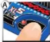
Press and hold the EZ-Set button (A). The LED will first turn green and then red. Release the button.
-
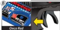
When the LED blinks RED ONCE. Pull the throttle trigger to the full throttle position and hold it there (B).
-
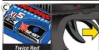
When the LED blinks RED TWICE. Push the throttle trigger to the full reverse and hold it there (C).
-
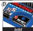
When the LED blinks GREEN ONCE, programming is complete. The LED will then shine green or red (depending on Low-Voltage Detection setting) indicating the XL-5 is on and at neutral (D).
Green then Red
XL-5 Operation
To operate the speed control and test the programming, reconnect the motor wires and place the vehicle on a stable block or stand so that all of the driven wheels are off the ground.
Note that in steps 1-8 below, Low-Voltage Detection is DISABLED (factory default) and the LED shines red. If Low-Voltage Detection is ACTIVATED, the LED will shine green instead of red in steps 1-8 below. Never use LiPo batteries while Low-
Voltage Detection is disabled.
-
With the transmitter on, press and release the EZ-Set button. The LED will shine RED. This turns the XL-5 on. If you press and release too quickly, you may hear the steering servo jump but the LED may not stay on. Simply press the button again until the LED shines RED and then release.
-
Apply forward throttle. The LED will turn off until full throttle power is reached. At full throttle, the led will shine RED.
-
Move the trigger forward to apply the brakes. Note that braking control is fully proportional. The LED will turn off until full braking power is reached. At full brakes, the LED will shine RED.
-
Return the throttle trigger to neutral. The LED will shine RED.
-
Move the throttle trigger forward again to engage reverse (Profile #1). The LED will turn off. Once full reverse power is reached, the LED will shine RED.
-
To stop, return the throttle trigger to neutral. Note that there is no programmed delay when changing from reverse to forward. Use caution to
14 • TRAXXAS
ADJUSTING THE ELECTRONIC SPEED CONTROL
avoid slamming the speed control from reverse to forward. On high-traction surfaces, this could result in transmission or driveline damage.
7. To turn the XL-5 off, press and hold the EZ-Set button for 1½ seconds or until the red LED turns off.
8. The XL-5 is equipped with thermal shutdown protection to guard against overheating caused by excessive current flow. If the operating temperature exceeds safe limits, the XL-5 will automatically shut down. The LED on the face of the XL-5 will rapidly blink red, even if the throttle trigger is moved back and forth. Once the temperature returns to a safe level, the XL-5 will once again function normally.
XL-5 Profile Selection
The speed control is factory set to Sport Mode (100% forward, brakes, and reverse). To disable reverse (Race Mode) or to allow 50% power (patent pending Training Mode), follow these steps. The speed control should be connected to the receiver and the transmitter adjusted as described previously. The profiles are selected by entering the programming mode.
Profile Description
Profile #1 (Sport Mode): 100% Forward, 100% Brakes, 100% Reverse Profile #2 (Race Mode): 100% Forward, 100% Brakes, No Reverse Profile #3 (Training Mode): 50% Forward, 100% Brakes, 50% Reverse
Selecting Sport Mode (Profile #1: 100% Forward, 100% Brakes, 100% Reverse)
- Turn on your transmitter and connect a fully charged battery pack to the XL-5.
- With the XL-5 off, press and hold the EZ-Set button until the LED turns solid green, then solid red and then begins blinking red (indicating the Profile numbers).
- When the LED blinks RED ONCE, release the EZ-Set button.
- The LED will blink and then turn solid green (Low-Voltage Detection ACTIVE) or red (Low-Voltage Detection DISABLED). The model is re
Selecting Race Mode (Profile #2: 100% Forward, 100% Brakes, No Reverse)
- Turn on your transmitter and connect a fully charged battery pack to the XL-5.
- With the XL-5 off, press and hold the EZ-Set button until the LED turns solid green, then solid red and then begins blinking red (indicating the Profile numbers).
- When the LED blinks RED TWICE, release the EZ-Set button.
- The LED will blink and then turn solid green (Low-Voltage Detection ACTIVE) or red (Low-Voltage Detection DISABLED). The model is ready to drive.
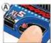
Green to Red to Off


One blink Red


Green to Red to Off


Two blinks Red

Selecting Training Mode (Profile #3: 50% Forward, 100% Brakes, 50% Reverse)
- Turn on your transmitter and connect a fully charged battery pack to the XL-5.
- With the XL-5 off, press and hold the EZ-Set button until the LED turns solid green, then solid red and then begins blinking red (indicating the Profile numbers).
- When the LED blinks RED THREE TIMES, release the EZ-Set button.
- The LED will blink and then turn solid green (Low-Voltage Detection ACTIVE) or red (Low-Voltage Detection DISABLED). The model is r
Note: If you missed the mode you wanted, keep the EZ-Set button pressed down and the blink cycle will repeat until the button is released and a Mode is selected.
LED Codes and Protection Modes

- Solid Green: XL-5 power-on light. Low-Voltage Detection is ACTIVATED (LiPo setting).

- Solid Red: XL-5 power-on light. Low-Voltage Detection is DISABLED (NiMH setting). Never use LiPo batteries while Low-Voltage Detection is disabled.

- Fast Blinking Red: The XL-5 is equipped with thermal shutdown protection to guard against overheating caused by excessive current flow. If the operating temperature exceeds safe limits, the XL-5 will automatically shut down. Let the XL-5 cool. Make sure your model is properly geared for the conditions.

- Slow Blinking Red (when Low-Voltage Detection is activated): The XL-5 has entered Low-Voltage Protection. When the battery voltage begins to reach the minimum recommended discharge voltage threshold for LiPo battery packs, the XL-5 will limit the power output to 50% throttle. When the battery voltage attempts to fall below the minimum threshold, the XL-5 will shut down all motor output. The LED on the speed control will slowly blink red, indicating a low-voltage shutdown. The XL-5 will stay in this mode until a fully charged battery is connected.

- Fast Blinking Green: The XL-5's LED will blink fast green if Throttle Neutral Protection is activated, or if the speed control is not receiving a signal. Make certain the speed control is properly plugged into the receiver and the transmitter is switched on. If this does not restore normal operation, then the XL-5 is indicating the transmitter's Throttle Trim is incorrectly set. Reset the throttle trim to the "0" position. See sidebar for more on Throttle Neutral Protection.

Green to Red to Off

Three blinks Red

1. 2017年1月1日


Patent-Pending Training Mode (Profile #3) reduces forward and reverse throttle by 50%. Training Mode is provided to reduce the power output allowing beginning drivers to better control the model. As driving skills improve, simply change to Sport or Race Mode for full-power operation.

Tip For Fast Mode Changes The XL-5 is set to Profile 1 (Sport Mode) as the default. To quickly change to Profile 3 (Training Mode), with the transmitter on, press and hold the EZ-Set button until the light blinks red three times and then release. For full power, quickly change back to Profile 1 (Sport Mode) by pressing and holding the EZ-Set button until the light blinks red one time and then releasing.

Throttle Neutral Protection The XL-5 speed control features Throttle Neutral Protection. If the transmitter's throttle trim setting is changed while the speed control is switched off, Throttle Neutral Protection prevents the speed control from activating the motor until the throttle trim is corrected. Throttle Neutral Protection also prevents the model from suddenly accelerating if the speed control is switched on while the transmitter's trigger is being held. When the trigger is returned to neutral, the XL-5 will operate properly.
DRIVING YOUR MODEL
Now it's time to have some fun! This section contains instructions on driving and making adjustments to your model. Before you go on, here are some important precautions to keep in mind.
- Allow the model to cool for a few minutes between runs. This is particularly important when using high capacity (2400mAh and above) battery packs that allow extended periods of running. Monitoring temperatures will extend the lives of the batteries and motor.
- Do not continue to operate the model with low batteries or you could lose control of it. Indications of low battery power include slow operation and sluggish servos (slow to return to center). Stop immediately at the first sign of weak batteries. When the batteries in the transmitter become weak, the red power light will begin to flash. Stop immediately and install new batteries.
- Do not drive the model at night, on public streets, or in large crowds of people.
- If the model becomes stuck against an object, do not continue to run the motor. Remove the obstruction before continuing. Do not push or pull objects with the model.
- Because the model is controlled by radio, it is subject to radio interference from many sources beyond your control. Since radio interference can cause momentary losses of control, allow a safety margin of space in all directions around the model in order to prevent collisions.
- Use good, common sense whenever you are driving your model. Intentionally driving in an abusive and rough manner will only result in poor performance and broken parts. Take care of your model so that you can enjoy it for a long time to come.
- When using the supplied optional pinions for top speed running, limit your driving to paved surfaces only. Running in grass and off-road could cause excessive loads on the electrical system in the model.
- The Titan 12T motor will benefit from a short break in period to ensure optimum performance and longer motor life. For the first battery pack, use the stock installed pinion gear and drive smoothly on a flat, paved surface. Accelerate smoothly (avoiding full throttle starts), with most of the driving being done at higher speeds. This will help insure that the motor provides the best performance and longest life.
About Run Time
A large factor affecting run time is the type and condition of your batteries. The milliamp hour (mAh) rating of the batteries determines how large their "fuel tank" is. A 3000 mAh battery pack will theoretically run twice as long as a 1500 mAh sport pack. Because of the wide variation in the types of batteries that are available and the methods with which they can be charged, it's impossible to give exact run times for the model. Another major factor which affects run time is how the model is driven. Run times may decrease when the model is driven repetitively from a stop to top-speed and with repetitive hard acceleration.
Tips for Increasing Run Time
- Use batteries with the highest mAh rating you can purchase.
- Use a high-quality peak-detecting charger.
- Read and follow all maintenance and care instructions provided by the manufacturer of your batteries.
- Vary your speed. The Titan12T is a fan cooled motor, therefore moderate to top-speed running helps reduce motor temperatures.
- Lower your gear ratio. Installing a smaller pinion gear will lower your gear ratio, causing less power draw from the motor.
- Maintain your model. Do not allow dirt or damaged parts to cause binding in the drivetrain. Keep the motor clean and the motor bushings lightly lubricated.
mAh Ratings and Power Output
The mAh rating of the battery can effect your top speed performance. The higher capacity battery packs experience less voltage drop under heavy load than low mAh rated packs. The higher voltage potential allows increased speed until the battery begins to become discharged.
RUNNING IN WET CONDITIONS
Your new Traxxas model is designed with water-resistant features to protect the electronics in the model (receiver, servos, electronic speed control). This gives you the freedom to have fun driving your model through puddles, wet grass, snow, and through other wet conditions. Though highly water resistant, the model should not be treated as though it is submersible or totally, 100% waterproof. Water resistance applies only to the installed electronic components. Running in wet conditions requires additional care and maintenance for the mechanical and electrical components to prevent corrosion of metal parts and maintain their proper function.

16 • TRAXXAS
DRIVING YOUR MODEL
Precautions
- Without proper care, some parts of your model can be seriously damaged due to contact with water. Know that additional maintenance procedures will be required after running in wet conditions in order to maintain the performance of your model. Do not run your model in wet conditions if you are not willing to accept the additional care and maintenance responsibilities.
- Not all batteries can be used in wet environments. Consult your battery manufacturer to see if their batteries can be used in wet conditions.
- The Traxxas TQ transmitter is not water resistant. Do not subject it to wet conditions such as rain.
- Do not operate your model during a rain storm or other inclement weather where lightning may be present.
- Do NOT allow your model to come in contact with salt water (ocean water), brackish water (between fresh water and ocean water), or other contaminated water. Salt water is highly conductive and highly corrosive. Use caution if you plan to run your model on or near a beach.
- Even casual water contact can reduce the life of your motor. Special care must be taken to modify your gearing and/or your driving style in wet conditions to extend the life of the motor (details follow).
Before Running Your Vehicle in Wet Conditions
- Consult the section "After Running Your Vehicle in Wet Conditions" before proceeding. Make sure you understand the additional maintenance required with wet running.
- The wheels have small holes molded in to allow air to enter and exit the tire during normal running. Water will enter these holes and get trapped inside the tires if holes are not cut in the tires. Cut two small holes (3mm or 1/8" diameter) in each tire. Each hole should be near the tire centerline, 180 degrees apart.
- Confirm that the RX box O-ring and cover are installed correctly and secure. Make sure the screws are tight and the blue O-ring is not visible protruding from the edge of the cover.
- Confirm that your batteries can be used in wet conditions.
- Use lower gearing (smaller pinion gears, as low as 12T or spur gear as large as 90T) when running in mud, deep puddles, snow, or other similar situations that will restrict the tires and put much higher loads on the motor.
Motor Precautions
- Titan motor life can be greatly reduced in mud and water. If the motor gets excessively wet or submerged, use very light throttle (run the motor slowly) until the excess water can run out. Applying full throttle to a motor full of water can cause rapid motor failure. Your driving habits will determine motor life with a wet motor. Do not submerge the motor under water.
- Do not gear the motor by temperature when running in wet conditions. The motor will be cooled by water contact and will not give an accurate indication of appropriate gearing.
After Running Your Vehicle in Wet Conditions
- Drain the tires by spinning the tires at high speed to "sling" the water out. One way to do this is to make several high-speed passes on a flat, dry surface, if possible.
- Remove the batteries.
- Rinse excess dirt and mud off the truck with low-pressure water, such as from a garden hose. Do NOT use pressure washer or other high-pressure water. Avoid directing water into the bearings, transmission, etc.
- Blow off the truck with compressed air (optional, but recommended). Wear safety glasses when using compressed air.
- Remove the wheels from the truck.
- Spray all the bearings, drivetrain, and fasteners with WD-40 ^* or similar water displacing light oil.
- Let the truck stand or you may blow off with compressed air. Placing the truck in a warm sunny spot will aid drying. Trapped water and oil will continue to drip from the truck for a few hours. Place it on a towel or piece of cardboard to protect the surface underneath.
- As a precautionary step, remove the sealed receiver box cover. While unlikely, humidity or tiny amounts of moisture or condensation may enter the receiver box during wet running. This can cause long-term problems with the sensitive electronics in the receiver. Removing the receiver box cover during storage allows the air inside to dry. This step can improve the long-term reliability of the receiver. It is not necessary to remove the receiver or unplug any of the wires.
- Additional Maintenance: Increase your frequency of disassembly, inspection and lubrication of the following items: This is necessary after extended wet use or if the vehicle will not be used for an extended period of time (such as a week or
DRIVING YOUR MODEL
longer). This additional maintenance is needed to prevent any trapped moisture from corroding internal steel components.
- Stub axle housing bearings: Remove, clean, and re-oil the bearings.
- Transmission: Remove, disassemble, clean, and re-grease the transmission components. Use a light coating of wheel bearing grease (from an auto parts store) on the metal gear teeth. Refer to your exploded view diagrams for help with disassembly and reassembly.
- Titan motor: Remove the motor, clean with aerosol motor cleaner, and re-oil the bushings with lightweight motor oil. Be sure to wear eye protection when using spray aerosol cleaners.
RECEIVER BOX: MAINTAINING A WATERTIGHT SEAL Removing and Installing Radio Gear
The unique design of the receiver box allows the removal and installation of the receiver without losing the ability to maintain a watertight seal in the box. The patent-pending wire clamp feature gives you the ability to also install aftermarket radio systems and maintain the watertight features of the receiver box.
Removing the Receiver
- Remove the wire clamp by removing the two 2.5x8mm cap screws.
- Remove the cover by removing the two 3x10mm cap screws.
- To remove the receiver from the box simply lift it out and set to the side. The antenna wire is still inside the clamp area and cannot be removed yet.
- Unplug the servo cables from the receiver and remove the receiver.
Receiver Installation
- Install the electronic speed control (ESC), servo, and antenna wiring through the receiver box top (A).
- Plug ESC and servo wires into the receiver (see page 8).
- Bundle wiring as necessary.
- Make sure the O-ring is properly seated into the groove in the receiver box bottom so that the cover will not pinch it or damage it in any way.
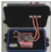
- Place receiver box top onto receiver box bottom and install and tighten the two 3x10mm cap screws securely.
- Inspect the cover to make sure that the O-ring seal is not visible.
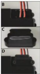
- Arrange the wires neatly using the wire guides on the receiver box top (B). Excess ESC and servo wiring should be bundled inside the receiver box. Pull out all available antenna wiring from the receiver box.
- Apply a small bead of silicone grease to the foam on the wire clamp (C).
- Install the wire clamp and tighten the two 2.5x8mm cap screws securely (D).
natural_image
Three-panel image showing a black mechanical component with red wires, labeled B, C, and D (no text or symbols on the components themselves)ADJUSTING YOUR MODEL
Once you become familiar with driving your model, you might need to make adjustments for better driving performance
Adjusting the Slipper Clutch The model is equipped with an adjustable slipper clutch which is built into the large spur gear.
The purpose of the slipper clutch is to regulate the amount of power sent to the rear wheels to prevent tire spin. When it slips, the slipper clutch makes a
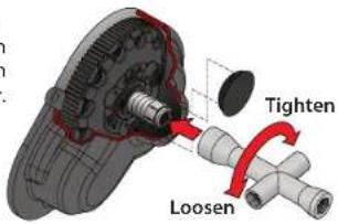
high-pitch, whining noise. Remove the rubber slipper clutch plug on the transmission cover in order to adjust the slipper. Use the 4-way wrench to turn the adjusting nut clockwise to tighten and counter-clockwise to loosen. Place the model on a high-traction surface, such as carpet. Adjust the slipper so that you can hear it slip for approximately two feet from a standing, full throttle start. (Learn more about adjusting the slipper clutch in the sidebar left.)
Adjusting the Toe-in
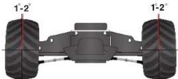
Geometry and alignment specs play an important roll in your model's handling. Take the time to set them correctly. Set the steering trim on your transmitter to neutral. Now, adjust your servo and tie rods so that both wheels are pointing straight ahead and are parallel to each other (0-degrees toe-in). This will ensure the same amount of steering in both directions.
For increased stability add one- to two-degrees of toe in to each front wheel. Use the turnbuckles to adjust the alignment.
natural_image
Diagram of a vehicle chassis with two wheels and two side bearings, showing angular measurement lines (no text or symbols)Fine Tuning the Shocks
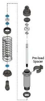
The four shocks on the model greatly influence its handling. Whenever you rebuild your shocks, or make any changes to the pistons, springs or oil, always make changes to them in pairs (front or rear). Piston selection depends on the range of oil viscosities that you have available. For example, using a two-hole piston with a
lightweight oil will, at one point, give you the same dampening as a three-hole piston with heavier oil. We recommend using the two-hole pistons with a range of oil viscosities from 10W to 50W (available from your hobby shop). The thinner viscosity oils (30W or less) flow more smoothly and are more consistent, while thicker oils provide more dampening. Use only 100% pure silicone shock oil to prolong seal life. The model's ride height can be adjusted by adding or removing the clip-on, spring pre-load spacers. Adjust the ride height so that the suspension arms are slightly above being parallel to the ground. Observe how the model handles in turns. Proper set-up will add stability and help prevent spin outs. Experiment with different springs and shock oils to find what works best for your current track conditions.
Wheels and Tires
Many types of aftermarket tires and wheels can be adapted for use on your model. Most will affect the overall width and the suspension geometry of the model. The offsets and dimensions designed into the model's wheels are intentional; therefore, Traxxas cannot recommend the use of other non-Traxxas wheels with different specifications. The diameter of the wheels is an innovative design, and there is a variety of different tires available for you to experiment with in addition to the included tires on the model (listed in your parts list). Experimentation with different types of tires is recommended to see which ones work the best on the terrain where the model is run. When selecting tires, consider the overall diameter and the rubber compound (hard or soft). If the overall diameter of the tire is significantly increased, you will need to use a smaller pinion gear to compensate for the larger tire. Soft compound tires with many short spikes generally work better on hard, dry surfaces. In loose dirt, a tire with large spikes should perform better. See your parts list for accessory wheels and tires.
Motors and Gearing
There are two different types of aftermarket motors which can be purchased for your model, stock and modified. Stock motors all have the same wire thickness and number of turns around the armature as governed by sanctioned racing organizations. They are inexpensive, and widely available. Modified motors are more expensive, may feature ball bearings and come in a variety of wire

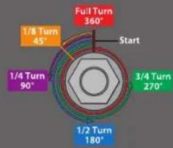
To achieve a good starting point for the slipper clutch in these models, tighten the slipper clutch adjusting nut clockwise until the slipper clutch adjusting spring fully collapses (do not over tighten), and then turn the slipper clutch nut counterclockwise one full turn.
other
| Turn Rate | Angle (°) | | :--- | :--- | | Full Turn | 360 | | 1/8 Turn | 45 | | 1/4 Turn | 90 | | 1/2 Turn | 180 | | 3/4 Turn | 270 | Start |
Do not run your model with the slipper clutch adjusting spring fully compressed. The minimum recommended slipper clutch setting is 1/2 turn counter-clockwise from fully compressed.
Gearing Compatibility Chart:
The chart below shows a full range of gear combinations. This does NOT imply that these gear combinations should be used. Over-gearing (bigger pinions, smaller spurs) can overheat and damage the motor and/or speed control.
Spur Gear
| Pinion Gear | 76 83 86 90 | |||
| 12 | -19.55 20.45 | |||
| 13 | -18.04 18.88 | |||
| 14 | -16.75 17.53 | |||
| 15 | -15.09 15.64 | 16.36 | ||
| 16 | -14.15 14.66 | |||
| 17 | -13.32 13.80 | 14.44 | ||
| 18 | -12.58 13.03 13.64 | |||
| 19 | -11.91 12.34 12.92 | |||
| 20 | -11.32 11.73 | 12.27 | ||
| 21 | -10.78 11.17 11.69 | |||
| 22 | -10.42 10.29 10.66 | 11.16 | ||
| 23 | -10.01 9.84 10.20 10.67 | |||
| 24 | -10.64 9.43 9.77 10.23 | |||
| 25 | -10.29 9.05 9.38 9.82 | |||
| 26 | -9.97 8.71 9.02 - | |||
| 27 | -9.68 8.38 8.69 - | |||
| 28 | -9.40 8.08 8.38 - | |||
| 29 | -9.15 7.81 8.09 - | |||
| 30 | -6.91 7.55 -- | |||
| 31 | -6.69 7.30 -- | |||
| 32 | -4.87 7.07 -- | |||
| 33 | -4.28 --- | |||
| 34 | -4.10 --- | |||
| 35 | -5.92 --- | |||
Stock gearing, recommended for most running, 6 or 7 cell NiMH, 2S LiPo.
Included optional gearing, for high-speed running only.
Usable gearing range.
High speed, Usable on hard surfaces.
Not recommended.
Does not fit.
20 • TRAXXAS
ADJUSTING YOUR MODEL
thicknesses and number of turns of wire on the armature. The fewer number of turns of wire on the armature, the more powerful the motor will be. Keep in mind that the more powerful the motor, the less battery run time you will have.
One of the more significant advantages to your model's transmission is the extremely wide range of available gear ratios. It can be geared low enough to run extremely hot, modified motors. Modified motors should be geared lower (higher numerically) than stock motors because they reach their maximum power at higher RPM's. A modified motor that is geared incorrectly can actually be slower than a correctly-geared, stock motor. Use the following formula to calculate the overall ratio for combinations not listed on the gear chart:
\# Spur Gear Teeth\# Pinion Gear Teeth × 2.72 = Final Gear Ratio
If you are worried that you might be over-geared, check the temperature of the battery pack and motor. If the battery is extremely hot, and/or the motor is too hot to touch, your model is probably over-geared. If you are not able to run your model for at least four minutes before the battery dies, then change to a lower gear ratio. This temperature test assumes that the model is close to factory stock weight and operates freely with no excessive friction, dragging, or binding, and the battery is fully charged and in good condition.
The model is equipped with a Titan 12T 550 motor. The gear combination that comes stock on the model provides good overall acceleration and top speed. If you want more top speed and less acceleration install the included high speed gearing (more teeth). If you want more acceleration and less top speed, use a smaller optional (not included) pinion gear. The included high speed gearing is intended for high-speed running on hard surfaces, and this gearing is not recommended for off-road or repetitive starting and stopping.
The Titan 12T is equipped with an integrated cooling fan that is effective during medium to high-speed operation. The gearbox is specially vented to cool the
motor. Repetitive starting and stopping over short distances creates excess heat and will not allow the fan to cool the motor properly. For this type of driving, smaller pinion gears are recommended to reduce load on the motor. See the guide below.
| • Fast Acceleration | 14-Tooth Pinion* |
| • Short Distances | 90-Tooth Spur |
| • Small Tracks | |
| • Good Acceleration | 16-Tooth Pinion |
| • Good Speed | 90-Tooth Spur |
| • Normal Conditions | |
| • High Top Speed | 21-Tooth Pinion |
| • Long Distances | 90-Tooth Spur |
| • Hard Surfaces |
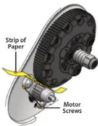
Adjusting Gear Mesh
Incorrect gear mesh is the most common cause of stripped spur gears. To set the gear mesh, cut a narrow strip of notebook paper and run it into the gear mesh. Loosen the motor screws and slide the motor and pinion gear into the spur gear. Retighten the motor screws and then remove the strip of paper. You should be able to run a fresh strip of paper through the gears without binding them.
Centering Your Servo
If the trim controls on your transmitter seem off, you may need to re-center your servo. Additionally, whenever your servo has been removed for service or cleaning, it must be re-centered prior to installation in the model.
- Disconnect the servo horn from the steering servo.
- Connect the steering servo to channel 1 on the receiver. Connect the electronic speed control (ESC) to channel 2. The white wire on the servo lead is positioned towards the crystal.
- Place fresh "AA" batteries in the transmitter and turn the transmitter power switch on.
- Turn the throttle and steering trim adjustments on the transmitter to the center "0" position.
- Elevate the rear wheels of the model. Connect a fresh 7.2V battery pack to the speed control and turn on the ESC (see page 13). The servo will automatically jump to its center position.
- Turn off the power to the model followed by the transmitter. The servo horn is now ready to be installed.
- Be careful not to move the servo shaft when installing the servo horn. Readjust the ESC as described in the "Adjusting the Speed Control" section.
14-Tooth Pinion* 90-Tooth Spur
16-Tooth Pinion 90-Tooth Spur
21-Tooth Pinion 90-Tooth Spur
14-Tooth Pinion* 90-Tooth Spur
16-Tooth Pinion 90-Tooth Spur
21-Tooth Pinion 90-Tooth Spur
14-Tooth Pinion* 90-Tooth Spur
16-Tooth Pinion 90-Tooth Spur
21-Tooth Pinion 90-Tooth Spur
14-Tooth Pinion* 90-Tooth Spur
16-Tooth Pinion 90-Tooth Spur
21-Tooth Pinion 90-Tooth Spur
14-Tooth Pinion* 90-Tooth Spur
16-Tooth Pinion 90-Tooth Spur
21-Tooth Pinion 90-Tooth Spur
14-Tooth Pinion* 90-Tooth Spur
16-Tooth Pinion 90-Tooth Spur
21-Tooth Pinion 90-Tooth Spur
14-Tooth Pinion* 90-Tooth Spur
16-Tooth Pinion 90-Tooth Spur
21-Tooth Pinion 90-Tooth Spur
14-Tooth Pinion* 90-Tooth Spur
16-Tooth Pinion 90-Tooth Spur
21-Tooth Pinion 90-Tooth Spur
14-Tooth Pinion* 90-Tooth Spur
16-Tooth Pinion 90-Tooth Spur
21-Tooth Pinion 90-Tooth Spur
*optional (sold separately)
MAINTAINING YOUR MODEL
Your model requires timely maintenance in order to stay in top running condition. The following procedures should be taken very seriously.
Inspect the vehicle for obvious damage or wear. Look for:
- Cracked, bent, or damaged parts
- Check the wheels and steering for binding.
- Check the operation of the shock absorbers.
- Check the wiring for any frayed wires or loose connections.
- Check the mounting of the receiver and servo(s) and speed control.
- Check the tightness of the wheel nuts with a wrench.
- Check the operation of the radio system, especially the condition of the batteries.
- Check for any loose screws in the chassis structure or suspension.
- The steering servo saver will wear out over time. If the steering becomes loose, the servo saver should be replaced.
- Inspect the gears for wear, broken teeth, or debris lodged between the teeth.
- Check the tightness of the slipper clutch.
Other periodic maintenance:
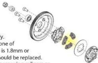
- Slipper clutch pads
(friction material):
Under normal use,
the friction material
in the slipper clutch
should wear very slowly.
If the thickness of any one of
the slipper clutch pads is 1.8mm or
less, the friction disc should be replaced.
Measure the pad thickness using calipers or
measuring against the diameter of the 1.5 and 2.0mm hex wrenches provided with the model.
- Chassis: Keep the chassis clean of accumulated dirt and grime. Periodically inspect the chassis for damage
Steering: Over time, you may notice increased looseness in the steering system. There are several components which will wear out from use: the servo saver (Traxxas part #3744), the bellcrank
bushings (Traxxas part #2545), and the tie rod ends (Traxxas part #2742). Replace these components as needed to restore factory tolerances.
Motor: Every 10-15 runs, remove, clean, and lubricate the motor. Use a product such as electric motor cleaning spray to flush dirt out of the motor. After cleaning, lubricate the bushings at each end of the motor with a drop of light-weight electric motor oil.
Shocks: Keep the oil level in the shocks full. Use only 100% pure silicon shock oil to prolong the life of the seals. If you are experiencing leakage around the top of the shock, inspect the bladder in the top cap for signs of damage or distortion from overtightening. If the bottom of the shock is leaking, then it is time for a rebuild. The Traxxas rebuild kit for two shocks is part #2362.
Suspension: Periodically inspect the model for signs of damage such as bent or dirty suspension pins, bent turnbuckles, loose screws, and any signs of stress or bending. Replace components as needed.
Driveline: Inspect the driveline for signs of wear such as worn drive yokes, dirty axle half shafts, and any unusual noise or binding. If a U-joint pops apart then it is time to replace the part. Remove the gear cover and Inspect the spur gear for wear and check the tightness of set screws in the pinion gears. Tighten, clean, or replace components as needed.
Storage
When you are through running the model for the day, blow it off with compressed air or use a soft bristled paint brush to dust-off the vehicle.
Always disconnect and remove the battery from the model whenever the model is stored. If the model will be stored for a long time, then also remove the batteries from the transmitter.

Always wear eye protection when using compressed air or spray cleaners and lubricants.

TRAXXAS • 21
NOTES
NOTES
MONSTER
JAM
United States
HOTROD
Association
[Non-Text]
TRAYAS
1100 KLEIN ROAD, PLANO TEXAS 75074
1-888-TRAXXAS
- TRAYAS
- INTRODUCTION
- Traxxas Support
- Quick Start
- BEFORE YOU PROCEED
- SUPPORT
- SAFETY PRECAUTIONS
- IMPORTANT POINTS TO REMEMBER
- SPEED CONTROL
- BATTERIES AND BATTERY CHARGING
- LiPo Batteries
- TOOLS, SUPPLIES AND REQUIRED EQUIPMENT
- QUICK START: GETTING UP TO SPEED
- THE TRAXXAS TQ RADIO SYSTEM
- RADIO AND POWER SYSTEM TERMINOLOGY
- Applying The Decals
- INSTALLING TRANSMITTER BATTERIES
- CHARGING THE BATTERY PACK
- Using Other Chargers
- Installing the Battery Pack
- The Traxxas High-Current Connector
- SETTING UP THE ANTENNA
- TQ RADIO SYSTEM ADJUSTMENTS
- Throttle Neutral Adjustment
- Electronic Throttle Trim
- Electronic Steering Trim
- Servo Reversing Switches
- TQ RADIO SYSTEM RULES
- TQ RADIO SYSTEM SETUP
- RANGE-TESTING THE TQ RADIO SYSTEM
- XL-5 Specifications
- ADJUSTING THE ELECTRONIC SPEED CONTROL
- Detection is disabled.
- XL-5 Profile Selection
- Profile Description
- LED Codes and Protection Modes
- DRIVING YOUR MODEL
- About Run Time
- Tips for Increasing Run Time
- mAh Ratings and Power Output
- RUNNING IN WET CONDITIONS
- Precautions
- Before Running Your Vehicle in Wet Conditions
- Motor Precautions
- After Running Your Vehicle in Wet Conditions
- RECEIVER BOX: MAINTAINING A WATERTIGHT SEAL Removing and Installing Radio Gear
- Removing the Receiver
- Receiver Installation
- ADJUSTING YOUR MODEL
- Adjusting the Slipper Clutch The model is equipped with an adjustable slipper clutch which is built into the large spur gear.
- Adjusting the Toe-in
- Fine Tuning the Shocks
- Wheels and Tires
- Motors and Gearing
- Gearing Compatibility Chart:
- \# Spur Gear Teeth\# Pinion Gear Teeth × 2.72 = Final Gear Ratio
- Adjusting Gear Mesh
- Centering Your Servo
- MAINTAINING YOUR MODEL
- Inspect the vehicle for obvious damage or wear. Look for:
- Other periodic maintenance:
- Storage
- MONSTER
- JAM
Brand : Traxxas
Model : Monster Jam
Category : Uncategorized