
DuraStation - Uncategorized GE - Free user manual and instructions
Find the device manual for free DuraStation GE in PDF.


| Product Type | Electric Vehicle Supply Equipment (EVSE) Charging Station |
| Model | GE DuraStation |
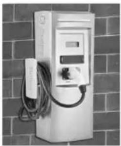
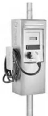
| Mounting Options | Pedestal, Double Pedestal (Back-to-Back), Wall-Mounted, Pole-Mounted |
| Dimensions (Wall-Mount) | 31.5" H x 14.9" W x 11.2" D |
| Weight (Wall-Mount) | 75 lb (34 kg) |
| Input Voltage | 208-240 VAC, Single Phase |
| Maximum Output Power | 7.2 kW (240 VAC @ 30 A) |
| Output Current | 30 A |
| Cable Length | 20 ft (6 m) |
| Connector | SAE J1772 compliant |
| Display | Vacuum Fluorescent Display (VFD) showing instructions, charging time, energy, and fault messages |
| Status Indicator | LED: Green (available), Blinking Green (connected, not charging), Amber (charging), Red (fault) |
| RFID Reader | Optional, ISO 15693 compliant, for user authorization |
| Network Connectivity | Ethernet (CAT5) with TCP/IP protocol; requires host PC for RFID authentication |
| Ground Fault Protection | Internal 20 mA CCID with auto-re-closure (after 15 min up to 4 attempts) |
| Operating Temperature | -30°C to +50°C (-22°F to 122°F) |
| Operating Humidity | Up to 95% non-condensing |
| Safety Compliance | UL 2231, UL 2251, UL 2594, cUL 2231, cUL 2594, NEC 625, SAE J1772 |
| Enclosure Rating | NEMA 3R (outdoor rated) |
| Surge Protection | 6 kV at 3000 A |
| EMI Compliance | FCC Part 15 Class A |
| Metering Accuracy | 2% on voltage/current, 4% on power/energy |
| Replacement Parts Available | Yes, including controller, RFID module, VFD display, service door, charging cord, etc. |
Frequently Asked Questions - DuraStation GE
User questions about DuraStation GE
0 question about this device. Answer the ones you know or ask your own.
Ask a new question about this device
Download the instructions for your Uncategorized in PDF format for free! Find your manual DuraStation - GE and take your electronic device back in hand. On this page are published all the documents necessary for the use of your device. DuraStation by GE.
USER MANUAL DuraStation GE
NEMA EVSE CHARGING STATION
USER MANUAL & INSTALLATION INSTRUCTIONS
natural_image
White electric vehicle charging station mounted on a brick wall, no visible text or symbolsWALL-MOUNT
natural_image
Exterior view of a white electric power station with visible circuit board and cable (no text or symbols)POLE-MOUNT
CONTENTS
1 Important Safety and Grounding Instructions....3
1.1 Safety and Compliance....3
1.2 Grounding Instructions 3
2 Installation Instruction 4
2.1 Before Installing....4
2.2 Safety Requirements....4
2.3 Installation Overview and Specifications 4
2.4 Pedestal 5
2.5 Double Pedestal (Back to Back)....12
2.6 Wall-Mounted 19
2.7 Pole-Mounted 25
2.8 Accessory Kits....31
2.9 Replacement Kits....31
2.9.1 RFID 33
2.9.2 VFD 40
2.9.3 Holding Socket 42
2.9.4 Service Door 44
2.10 Wiring Diagram....45
3 User Manual 46
3.1 Receiving 46
3.2 Basic User Instructions....47
3.3 Technical Data 51
3.4 Additional Considerations....53
3.5 EVSE Controller Settings 53
3.5.1 Configuration Switch Settings 53
3.5.2 Display fault messages 55
4 Network Setup Instructions....58
4.1 Definitions and Terms....58
4.2 Firewall and Security Considerations....58
4.3 Controller Configuration....59
4.3.1 Introduction....59
4.3.2 Prepare Service Laptop or PC 59
4.3.3 EVSE Configuration Server Interface 61
4.4 Recommended Network Designs for RFID Authentication 67
4.4.1 Option 1: Stand-alone Network Configuration....67
4.4.2 Option 2: Charging Station Network isolated from Customer Network with Host System in a DMZ.....73
4.4.3 Install EV100 RFID Host Application Software....79
4.4.4 Setup Validation....80
4.5 Setup without RFID Authentication....82
4.6 Reset Controller to Factory Default 83
4.7 Trouble Shooting Guide 84
1 Important Safety and Grounding Instructions
1.1 Safety and Compliance

WARNING:
Read all the instructions before using this product.
This device should be supervised when used around children.
Do not put fingers into the electric vehicle connector.
Do not use this product if the flexible power cord or EV cable are frayed, have broken insulation, or any other signs of damage.
Do not use this product if the enclosure or the EV connector are broken, cracked, open, or show any other indication of damage.
This document provides instructions for installation of EV Charging Station products listed in Table 11 in Section 3.3, and should not be used for any other product. Before installing the EVSE (Electric Vehicle Supply Equipment), you should review this manual carefully and consult with a licensed contractor, licensed electrician, or trained installation expert to ensure compliance with local building codes, climate conditions, safety standards and state and local electrical codes.
The EVSE should be installed only by a licensed contractor, and/or a licensed electrician in accordance with all applicable state, local and national electrical codes and standards. The EVSE should be inspected by a qualified installer prior to initial use. Under no circumstances will compliance with the information in this manual relieve the user of his/her responsibility to comply with all applicable codes or safety standards.
1.2 Grounding Instructions
The EVSE must be connected to a grounded, metal, permanent wiring system, or an equipment grounding conductor. This should be run with circuit conductors and connected to the equipment grounding bar or lead on the EVSE. Connections to the EVSE shall comply with all applicable electrical codes and ordinances.
2 Installation Instruction
2.1 Before Installing
Before any installation work is performed, study all drawings furnished by the supplier for the particular installation.
These include arrangement drawings (front, end, and plan views), connections to the equipment that may be required to meet any local codes (such as mats, screens, or railings) is not furnished.
2.2 Safety Requirements
• Eye protection with appropriate glasses (especially when using the electrical drill).
- In the installation be sure to not connect directly to power distribution network cables without additional protection.
- Ensure that at all times when working, no power is connected.
- Use appropriate tools for each function.
2.3 Installation Overview and Specifications
This document describes how to install any EVSE charging station family.
It includes step-by-step instructions for installing the body assembly for the following stations:
- Pedestal
• Double Pedestal (Back to Back) - Wall-Mounted
- Pole-Mounted
To ensure that the EVSE is installed per Americans with Disabilities Act (ADA) Standards for Accessible Design guidelines, refer to code of federal regulations document 28 CFR Part 36, sections 4.2 (Space Allowance and Reach Ranges) and 4.4 (Protruding Objects).
EVSE Torque Specification Table
| SCREW SIZE | TORQUE | TORQUE TOL. |
| 6-32 UNC | 13 in-lb | +/- 2 in-lb |
| 10-32 UNF | 30 in-lb | +/- 5 in-lb |
| 1/4-20 UNC | 53 in-lb | +/- 7 in-lb |
| 1/2-13 UNC | 48 in-lb | +/- 7 in-lb |
| M6 x 1 LIGUIDTIGHT FITTING | 30 in-lb | +/- 5 in-lb |
| FUSE BLOCK LUGS, 8 AWG | 40 in-lb | +/- 5 in-lb |
| FUSE BLOCK LUGS, 6 AWG | 45 in-lb | +/- 5 in-lb |
| GROUND TERM. SCREWS, 14-10 AWG | 34 in-lb | +/- 5 in-lb |
| GROUND TERM. SCREWS, 8 AWG | 38 in-lb | +/- 5 in-lb |
| 3/4" LOCKNUT | HAND TIGHT + 1/4 TURN | n/a |
- Table 1 -
Tools
| Type | Characteristics |
| Slotted Screwdriver | 3/16" or 1⁄4" |
| Phillips Screwdriver | #2 |
| Socket | Socket sizes: 7/16", 3⁄4" |
| Electric Drill | Used in the wall mounted and pole mounted installations |
| Wire stripper, hammer, and wall anchors | |
- Table 2 -
Field cable size: Single Pedestal, Wall Mount and Pole Mount:
Cu: 8 AWG, minimum 75 °C wire
Al: 6 AWG, minimum 75 °C wire
Double Pedestal:
Cu: 8 AWG, minimum 90 °C wire
Al: 6 AWG, minimum 90 °C wire

WARNING: Make sure power to the EVSE is disconnected before performing any task
2.4 Pedestal
Bill of materials
| ITEM | DESCRIPTION | QTY |
| 1 | Kiosk Pedestal Unit | 1 |
| 2 | Base Mounting Assembly | 1 |
| 3 | Kiosk Skirting | 1 |
| 4 | Base Mounting Template, NEMA 3R | 1 |
| 5 | Hex Nut, 12 " SS | 12 |
| 6 | Star Washer, External Tooth, 12 " SS | 8 |
- Table 3 -
Procedure
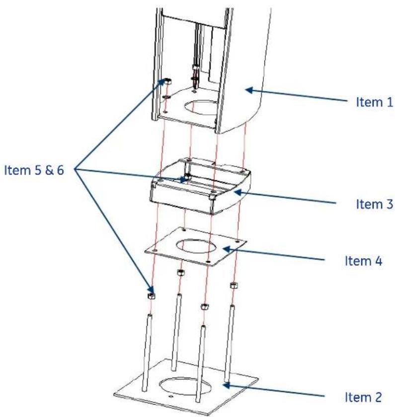
Figure 1: Exploded pedestal base assembly
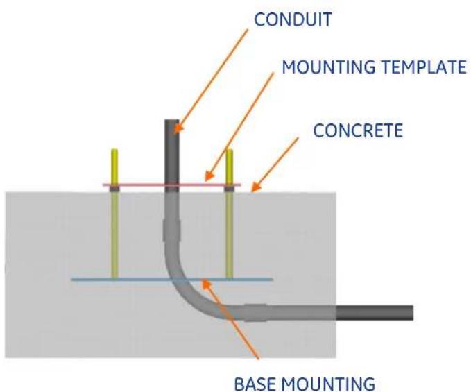
Figure 2
natural_image
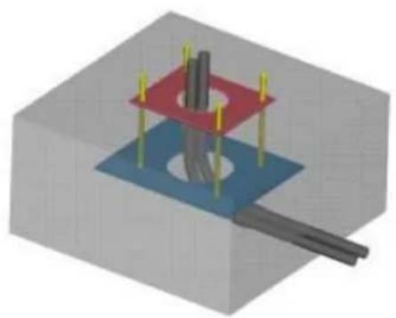
3D mechanical assembly diagram showing a bolted joint with red and blue plates and yellow pins (no text or symbols)Figure 3
Locate area for pedestal location.

WARNING: Make sure power to the EVSE is disconnected before performing any task
Install two conduits, one for power, and one for communication (if required). Allow approximately 5" length for each conduit above the concrete level as shown in Figure 4. Cut as necessary to final dimensions. Route power conduit and communication conduit through the center of the hole in the mounting template, appropriately.
Install base mounting assembly plate securely over conduits with mounting template and four 1/2-13 nuts.
5.50
Figure 4
BASE MOUNTING ASSEMBLY – DURING CONCRETE POUR. ALLOW MIN. 5" CONDUIT LENGTH ABOVE CONCRETE FLOOR LEVEL
Adjust (4) 12 -13 nuts to position height as shown in Figure 4.
Pour concrete to level shown in Figure 4. Do not cover the 12 -13 nuts with concrete. Remove mounting template from threaded rods, after concrete has cured. Do not remove the 12 -13 nuts as they are used for leveling the skirt.
CONDUIT
KIOSK
12 -13 NUT, AND
STAR WASHER
Figure 5
PEDESTAL SKIRT INSTALLATION, AFTER CONCRETE POUR
Install 12 -13 nuts and star washers after lowering skirt over matching threaded rods over the 12 -13 nuts. Use the bottom 12 -13 nuts for leveling the skirt. Fasten nuts and skirt assembly to concrete base, as shown in Figure 5. Torque nuts per specification Table 1

EV Charging Station
User Manual & Installation Instructions
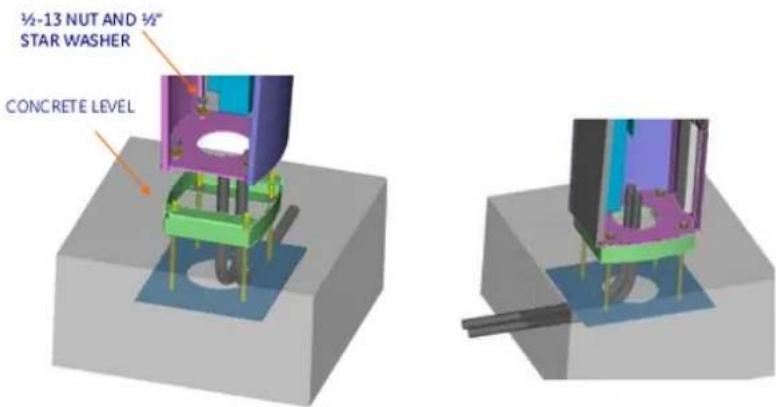
Figure 6
Figure 7
Open the door by pressing the round button on the door latch. Insert the Kiosk from top and install 12 -13 nuts and star washers after lowering skirt over matching threaded rods as shown in the Figures 6 and 7.
Torque all the nuts as per the torque specification in Table 1 (recommended tool: 3/8" drive quick release ratchet & 13/16 socket).
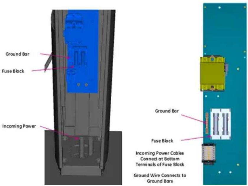
Connect L1 and L2 to the fuse block and ground wire to the ground bar shown in Figure 8.
IMPORTANT: FV Charging Station is rated for 208-240V power only. The EVSE must be connected to a
natural_image
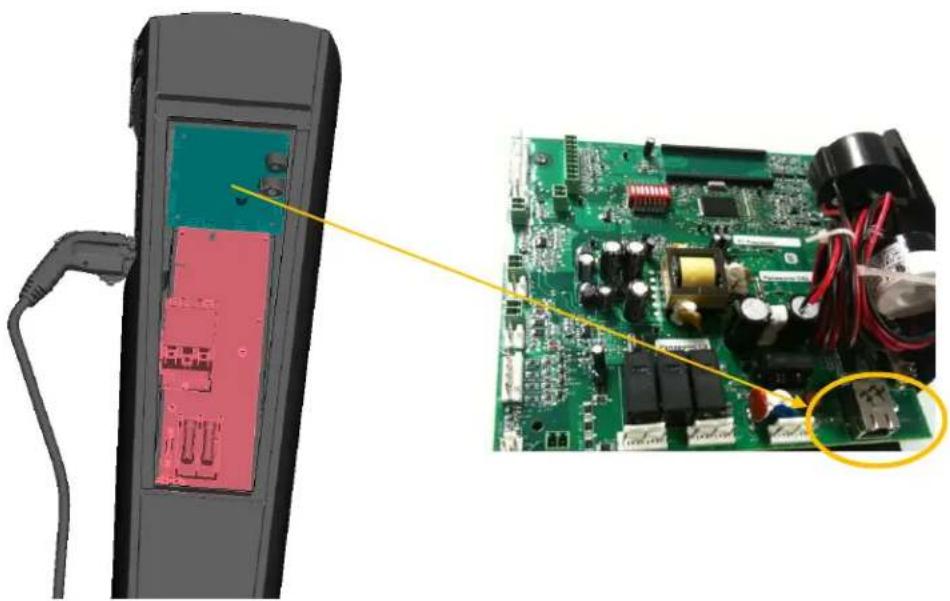
Close-up of a handheld electronic device with an open circuit board and a close-up of its internal components (no visible text or symbols)Figure 9 : Ethernet Connection to Controller for Pedest
2.5 Double Pedestal (Back to Back)
Bill of materials
| ITEM | DESCRIPTION | QTY |
| 1 | Kiosk Pedestal Unit | 1 |
| 2 | Base Mounting Assembly | 1 |
| 3 | Kiosk Skirting | 1 |
| 4 | Base Mounting Template, NEMA 3R | 1 |
| 5 | Hex Nut, 12 " SS | 12 |
| 6 | Star Washer, External Tooth, 12 " SS | 8 |
- Table 4 -
Procedure
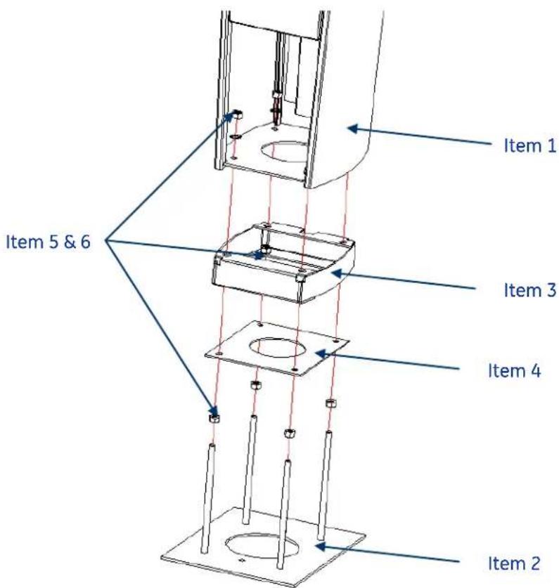
Figure 10: Exploded double pedestal base assembly
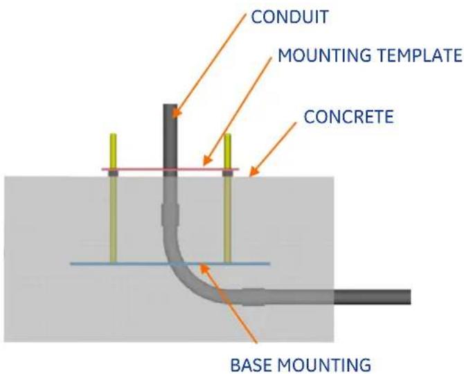
Figure 11
natural_image
3D mechanical assembly diagram showing a bolted joint with red and blue plates and yellow pins (no text or symbols)Figure 12
Locate area for double pedestal location.

WARNING: Make sure power to the EVSE is disconnected before performing any task
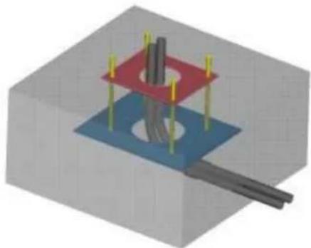
Install conduits for power wire and communication wire (if required). Allow approximately 5" length for each conduit above the concrete level as shown in Figure 13. Cut as necessary to final dimensions. Route power conduit and communication conduit through the center of the hole in the mounting template, appropriately.
Install base mounting assembly plate securely over conduits with mounting template and four 1/2-13 nuts.
5.50
Figure 13
BASE MOUNTING ASSEMBLY - DURING CONCRETE POUR. ALLOW MIN. 5" CONDUIT LENGTH ABOVE CONCRETE FLOOR LEVEL
Adjust (4) 12 -13 nuts to position height as shown in Figure 13.
Pour concrete to level shown in Figure 13. Do not cover the 12 -13 nuts with concrete. Remove mounting template from threaded rods after concrete has cured. Do not remove 12 -13 nuts as they are used for leveling the skirt.
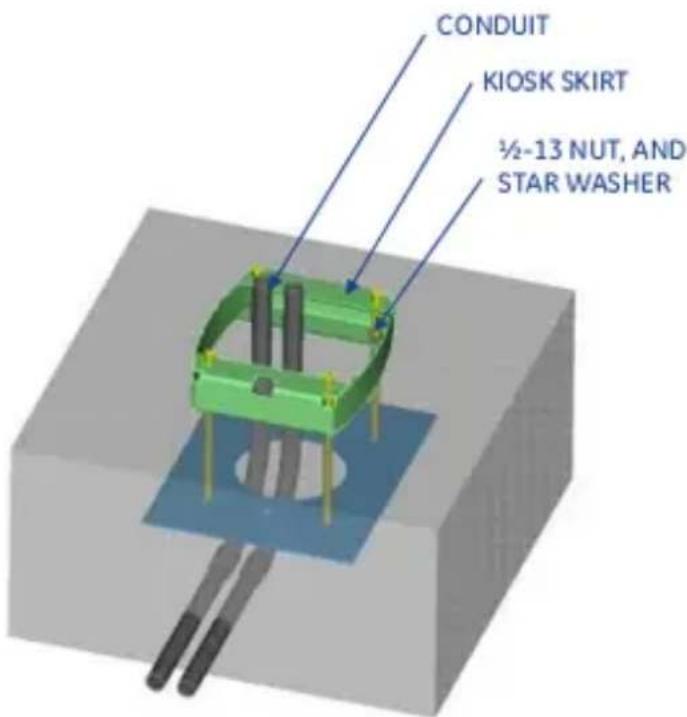
Figure 14
DOUBLE PEDESTAL SKIRT INSTALLATION, AFTER CONCRETE POUR
Install 12 -13 nuts and star washers after lowering skirt over matching threaded rods over the 12 -13 nuts. Use the bottom 12 -13 nuts for leveling the skirt. Fasten nuts and skirt assembly to concrete base, as shown in Figure 14. Torque nuts per specification Table 1.
12 -13 NUT AND 12 " STAR WASHER
CONCRETE LEVEL
Figure 15
Figure 16
Open the door by pressing the round button on the door latch. Insert the Kiosk from top and install 12 -13 nuts and star washers after lowering skirt over matching threaded rods as shown in Figures 15 and 16.
Torque all the nuts as per the torque specification in Table 1 (recommended tool: 3/8" drive quick release ratchet and 13/16" socket)
Connect L1 and L2 of circuit 1 and 2 to the fuse block lugs 1 and 2 respectively. Connect ground wire of circuit 1 and 2 to the ground bar 1 and 2 respectively as shown in Figure 17.
IMPORTANT: EV Charging Station is rated for 208-240V power only. The EVSE must be connected to a grounded, metal, permanent wiring system, or an equipment grounding conductor. This should be run with circuit conductors and connected to the equipment grounding bar or lead on the EVSE. Connections to the EVSE shall comply with all applicable electrical codes and ordinances.
In case of RFID sensor, the communication cable is connected to the Ethernet connector on controller 1 and 2 as shown in Figure 18.
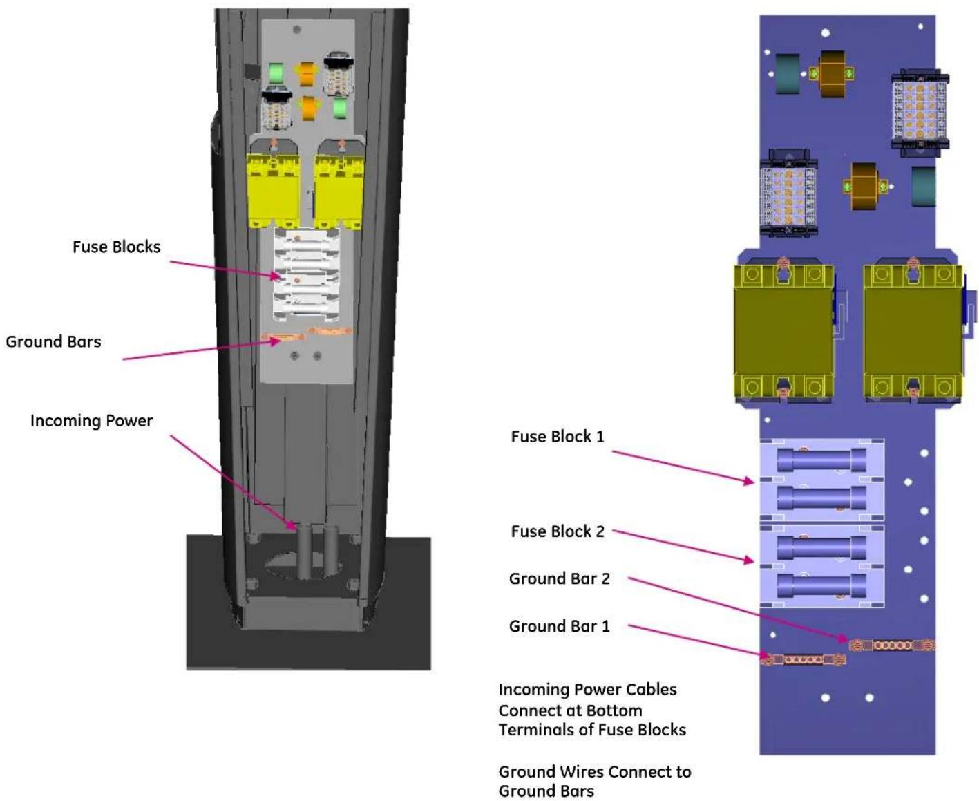
Figure 17: Power Wire and Ground Wire Connections for Double Pedestal
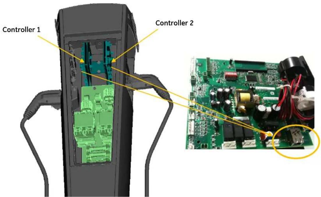
Figure 18: Ethernet Connection to Controller for Double Pedestal
2.6 Wall-Mounted
Bill of materials
| ITEM | DESCRIPTION | CHARACTERISTICS | QTY |
| 1 | Kiosk Unit | Wall mounted enclosure | 1 |
| 2 | Wall Bracket Assembly | (4) 1/4"-20 Weld Stud | 1 |
| 3 | Hex. Nuts 1/4"-20 | Zinc Plated Steel | 4 |
| 4 | Sealing Washer, 1/4" dia. | Seals 1/4" studs | 4 |
| 5 | Conduit Hub, 3/4" | Attach to 3/4" conduits/enclosure | 2 |
- Table 5 -
Procedure

WARNING: Make sure power to the EVSE is isconnected before performing any task
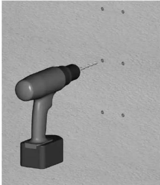
Drill 6 holes in the wall as illustrated in Figure 19. Use the supplied wall-mounting bracket to ensure correct alignment. The height of the bottom hole from the floor should be between 19" to 25" to
ensure meet UL and American Disability Act compliance. This will ensure the critical height shown in Figure 21.
IMPORTANT: Exercise extreme caution when drilling holes in the wall. Make sure there are no electrical cables.
natural_image
3D rendered image of a handheld electric shaver with a pointed tip, against a textured gray background (no text or symbols)Figure 19: Wall-Mount Bracket Holes
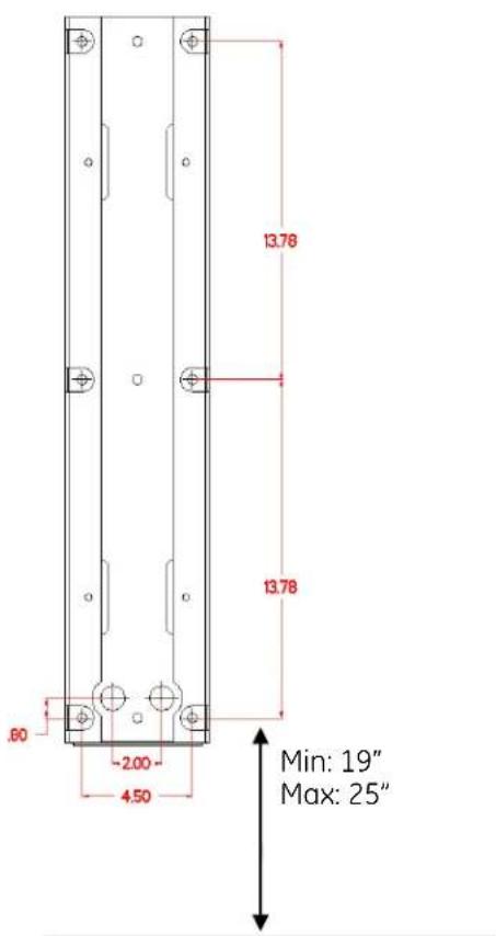
Figure 20: Wall-Mount Bracket
Fasten the wall bracket to the wall. Refer to Table 6 for recommended wall mounting fasteners. Supply two 3/4'' conduits (one for power cable and other one for communication cable) as per bracket drawing dimensions and connect supplied 3/4'' conduit hubs to conduits. If the communication cable and the corresponding conduit is not used, cover the hole with supplied NEMA 3R knockout plugs.
Optionally, the power wire can be run through the bottom of the enclosure. See page 24.
MIN: 18"
MAX: 24"
Figure 21: Wall Mount Installation, Critical Dimension
Wall Mount EVSE Mounting Fasteners
| Fastener Type | Supplier | Part Number | Qty | Application | Image |
| 3/8" x 1-7/8" Concrete Anchor Pre-drill hole dia. 3/8" | McMaster-Carr | 96892A258 | 6 | Concrete Wall | 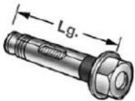 WithHex Nut WithHex Nut |
| 3/8" x 1-3/4" Concrete Hex Screw Pre-drill hole dia. 5/16" | Tapcon | LDT38134 | 6 | Concrete Wall | 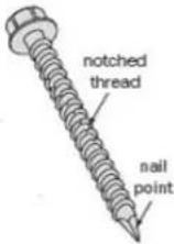 |
| 3/8" x 2" Hex Head Lag Bolt Pre-drill hole dia. 3/8" Hardwood Pre-drill hole dia. 1/4" Softwood | McMaster-Carr | 95526A525 | 3 | Stud Wall (into wood stud) |  |
| Hollow Wall Anchor Pre-drill hole dia. 3/8" | Cobra Anchors | TripleGrip | 6 | Drywall (into sheetrock) | 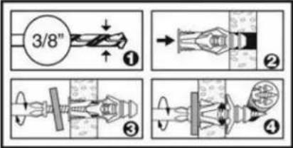 |
- Table 6 -
The cables must extend 16" to 24" above the wall surface, or according to local codes.
Pull L1, L2 and ground wire into the enclosure assembly through the conduit hub. Similarly pull the communication cable into the enclosure assembly through the second conduit.
IMPORTANT: EV Charging Station is rated for 208-240V power only. The EVSE must be connected to a grounded, metal, permanent wiring system, or an equipment grounding conductor. This should be run with circuit conductors and connected to the equipment grounding bar or lead on the EVSE. Connections to the EVSE shall comply with all applicable electrical codes and ordinances.
Install the enclosure on the wall-mounting bracket. Insert the threaded portion of the conduit hub into the hole of the enclosure. Fasten the conduit hub using the nut. Fasten the enclosure to the wall-mounting bracket using the self-sealing washers and nuts from inside the enclosure as indicated in Figure 22.
Torque all the nuts as per the torque specification in Table 1.
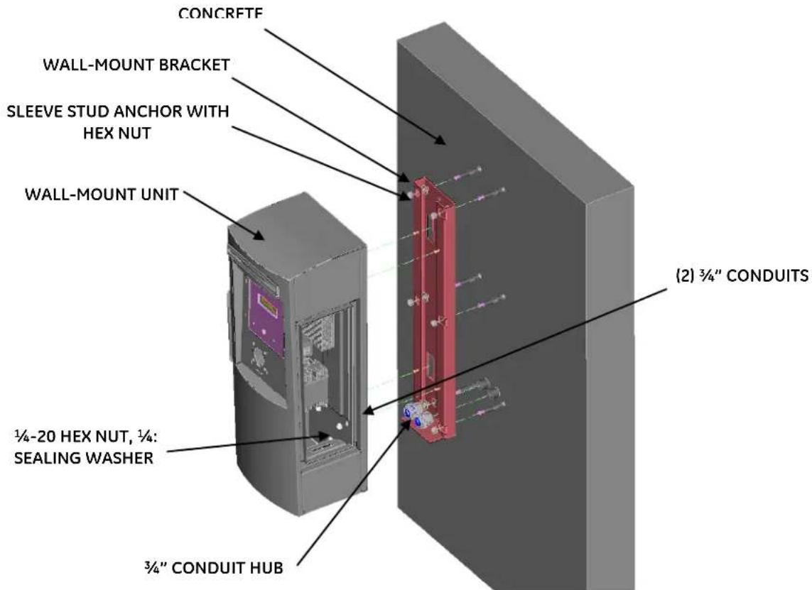
Figure 22: Wall-Mount Installation, Exploded View
Connect L1, L2 to the fuse block and ground wire to the ground bar shown in Figure 23.
In case of RFID sensor, the communication cable is connected to the Ethernet connector on the controller, just like the pedestal as shown in Figure 9.
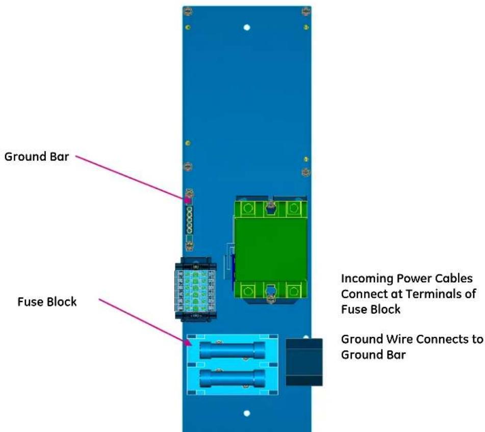
Figure 23: Power Wire and Ground Wire Connections for Wall Mount
Field wiring entry from bottom:
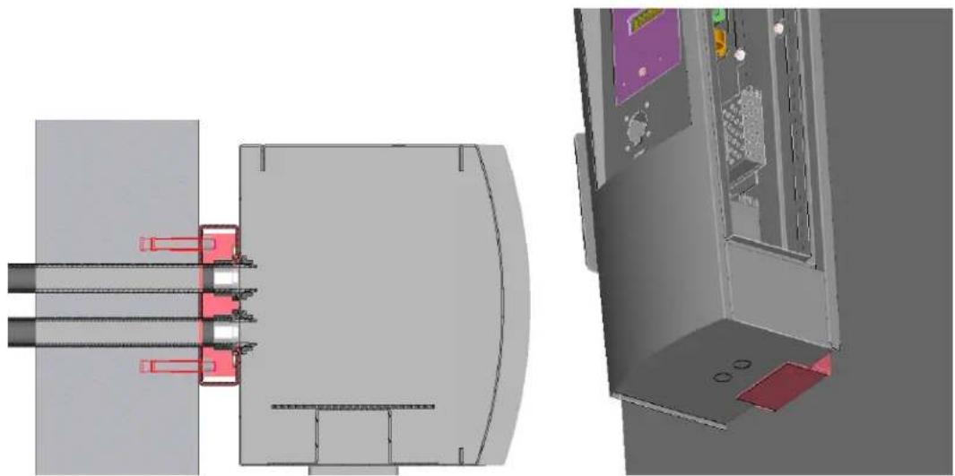
If this option is preferred, remove the two knockouts at the bottom of the enclosure and fill in the unused cable holes on the back of the enclosure using the spare NEMA 3R knockout plugs provided. See Figure 24. Assemble the supplied conduit hub in the bottom and make the conduit arrangement.
natural_image
3D CAD model of a mechanical assembly with internal components and mounting features (no visible text or symbols)Figure 24: Wall-Mount Conduit Installation Default (left) and Alternate (right) Fitting Locations
2.7 Pole-Mounted
Bill of materials
| ITEM | DESCRIPTION | CHARACTERISTICS | QTY |
| 1 | Kiosk Unit | Pole-Mounted | 1 |
| 2 | Pole-bracket Assembly | Bracket & 3/4" Banding | 1 |
| 3 | Band Clamp | 3/4" Stainless Steel Clamp | 2 |
| 4 | Hex. Nuts 1/4-20 | Supplied with EVSE unit | 4 |
| 5 | Sealing Washers, 1/4" | Seals 1/4" studs | 4 |
| 6 | Conduit Hub, 3/4" | Attach to 3/4" conduits/enclosure | 2 |
| 7 | Conduit Nipple (Installer supplied) | 3/4" pipe size, 1.05"OD, NPTXNPT threaded both ends Nipple. Example: Metallic - McMaster Carr part 7727K225 or similar suitable plastic conduit nipple | 2 |
- Table 7 -
Procedure

WARNING: Make sure power to the EVSE is disconnected before performing any task
IMPORTANT: Possible pole diameters for these EVSE units are 8" to 12".
Drill two holes of diameter 1 1/8" on the pole in the location shown in Figure 25. One hole is to bring the power cables and the other for communication cable into the enclosure. If the communication cable and the corresponding conduit is not used, cover the hole in the enclosure with the supplied NEMA 3R knockout plug and do not drill the corresponding hole in the pole. The height of the holes from the floor should be from 20" to 25" as shown in Figure 25 to meet UL and American Disability Act compliance. This ensures the critical height shown in Figure 26.
IMPORTANT: Exercise extreme caution when drilling holes in the wall. Make sure there are no electrical cables.
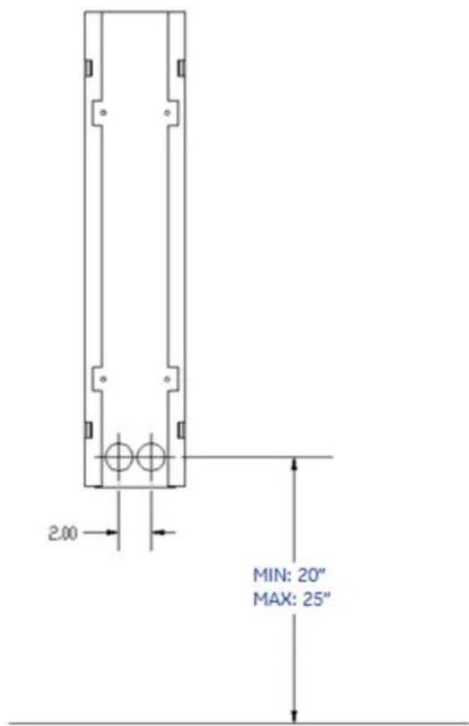
Figure 25: Pole mount drilling dimension
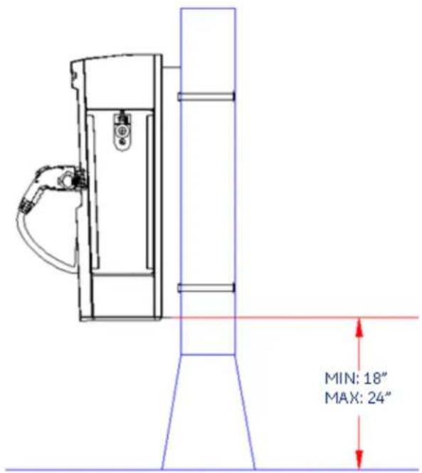
Figure 26: Pole Mount Installation, Critical Dimension
Optionally, the power wire can be run through the bottom of the enclosure. See page 29.
Insert the threaded portion of the conduit hub into the enclosure hole and fasten the conduit hub using the nut. Connect 34 " conduit nipple (Installer supplied) with minimum 3" length up to 4" length to the conduit hub.
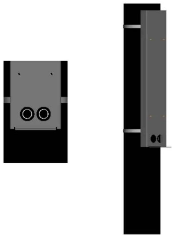
Align the mounting bracket to the pole, ensuring the coupler opening in the bracket is centered over the hole in the pole bracket assembly as shown in Figure 27.
Strap the pole bracket assembly to the pole by supplied 3/4'' by 0.030" stainless steel banding as shown in the Figure 27.
IMPORTANT: You must use a high tension-banding tool to install bands. (GE Part no: EVPMBAND)
natural_image
Two 3D mechanical components with circular ports, shown from different angles (no text or symbols)Figure 27 : Mounting bracket alignment to the holes
The cables must extend 16" to 24" above the pole surface, or according to local codes.
Pull L1, L2 and ground wire into the enclosure assembly through the conduit hub. Similarly pull the communication cable into the enclosure assembly through the second conduit.
Install the Kiosk pole mounted unit, using the nuts and sealing washers as shown in Figure 28.
Torque all the nuts as per the torque specification in Table 1.
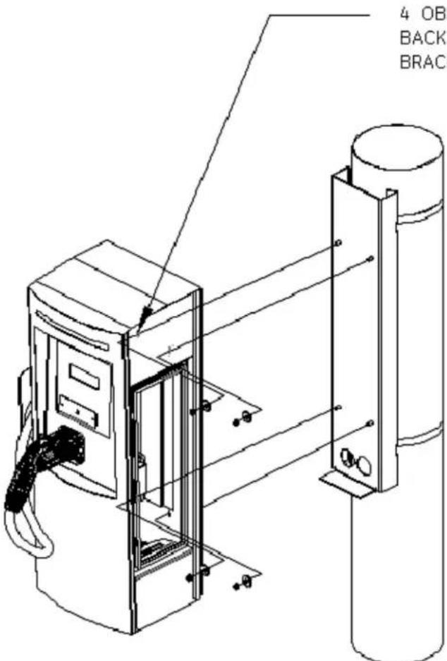
4 OBLONG HOLES ON
BACK OF ENCLOSURE FOR
BRACKET MOUNTING
Figure 28: Pole-Mount Installation, Exploded View
IMPORTANT: EV Charging Station is rated for 208-240V power only. The EVSE must be connected to a grounded, metal, permanent wiring system, or an equipment grounding conductor. This should be run with circuit conductors and connected to the equipment grounding bar or lead on the EVSE. Connections to the EVSE shall comply with all applicable electrical codes and ordinances.
Connect L1, L2 to the fuse block and ground wire to the ground bar shown in Figure 23.
In case of RFID sensor, the communication cable is connected to the Ethernet connector on the controller, just like the pedestal as shown in Figure 9.
Field wiring entry from bottom:
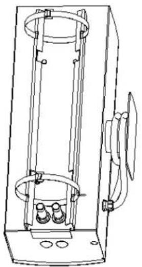
If this option is preferred, remove the two knockouts at the bottom of the enclosure and fill in the unused cable holes on the back of the enclosure using the spare NEMA 3R knockout plugs provided. See Figure 30. Assemble the supplied conduit hub in the bottom and make the conduit arrangement.
natural_image
Technical line drawing of a vertical mechanical device with internal components and mounting holes (no text or symbols)Figure 29: Pole-Mount Conduit Using Side Fitting Installations
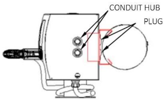
Figure 30: Alternate Pole-Mount Conduit Installation Using Bottom Knockouts
2.8 Accessory Kits
The EV Charging Station offers the following accessory kits:
| Ordering Number | Description |
| EVRP01 | RFID enrollment reader CM5321CL USB – 13.45MHz |
| EVRP02 | RFID enrollment reader CM5325CL USB – 125kHz |
| EVRP03 | RFID enrollment reader RP40 USB - universal |
| EV100CD | CD with standalone SW EV100 |
| EVRCW50 | Pack of 10 white RIFD cards |
| EVRCG50 | Pack of 10 GE US RFID cards |
| EVPMBAND | Pole mount strap installation kit |
- Table 8 -
2.9 Replacement Kits
The EV Charging Station offers the following replacement kits:
| Ordering Number | Description |
| EVDSCTL01 | EVSE WALLMOUNT - BASIC - Controller Replacement + harness |
| EVDSCTL02 | EVSE WALLMOUNT WITH RFID - Controller Replacement + harness |
| EVDSCTL03 | EVSE POLEMOUNT BASIC - Controller Replacement + harness |
| EVDSCTL04 | EVSE POLEMOUNT WITH RFID - Controller Replacement + harness |
| EVDSCTL05 | EVSE OUTDOOR PEDESTAL BASIC - Controller Replacement + harness |
| EVDSCTL06 | EVSE OUTDOOR PEDESTAL WITH RFID - Controller Replacement + harness |
| EVDSCTL07 | EVSE OUTDOOR DOUBLE PEDESTAL BASIC - Controller Replacement + harness |
| EVDSCTL08 | EVSE OUTDOOR DOUBLE PEDESTAL WITH RFID - Controller Replacement + harness |
| EVDSLED01 | LED Replacement - EVSE OUTDOOR PEDESTAL |
| EVDSLED02 | LED Replacement - EVSE WALLMOUNT/ POLE MOUNT |
| EVDSLED03 | LED - EVSE OUTDOOR DOUBLE PEDESTAL |
| EVDSRR01 | RFID Replacement |
| EVDSVFD01 | VFD display replacement kit |
| EVDSDR01 | Service door wall-mount |
| EVDSDR02 | Service door pedestal |
| EVDSFIX01 | Replacement Hardware Kit |
| EVDSSK01 | Holding Socket Inlet Replacement |
| EVDSCBL01-20 | EVSE OUTDOOR PEDESTAL - Charging Cord Replacement |
| EVDSCBL02-20 | EVSE OUTDOOR WALL MOUNT/ POLE MOUNT - Charging Cord Replacement |
| EVDSCBL03-20 | EVSE OUTDOOR DOUBLE PEDESTAL - Charging Cord Replacement |
| EVDSPD01 | Replacement Protective Devices |
| EVDSCT01 | CT Replacement |
| EVDSCR01 | Contactor Replacement |
| EVDSKIT01 | Wire harness replacement kit - EVSE WALLMOUNT - BASIC |
| EVDSKIT02 | Wire harness replacement kit - EVSE WALLMOUNT - WITH RFID |
| EVDSKIT03 | Wire harness replacement kit - EVSE POLEMOUNT - BASIC |
| EVDSKIT04 | Wire harness replacement kit - EVSE POLEMOUNT - WITH RFID |
| EVDSKIT05 | Wire harness replacement kit - EVSE OUTDOOR PEDESTAL - BASIC |
| EVDSKIT06 | Wire harness replacement kit - EVSE OUTDOOR PEDESTAL - WITH RFID |
| EVDSKIT07 | Wire harness replacement kit - EVSE OUTDOOR PEDESTAL DOUBLE PEDESTAL - BASIC |
| EVDSKIT08 | Wire harness replacement kit - EVSE OUTDOOR DOUBLE PEDESTAL - WITH RFID |
| EVDSLBL01 | Pack of labels |
| EVDSMAN01 | EVSE User Manual and Installation instruction |
- Table 9 -
The following replacement kits can be installed by the customer: RFID (EVDRR01) (except for double pedestal), VFD (EVDSVFD01) (except for double pedestal), holding socket inlet (EVDSSK01) (except for double pedestal) and service door (EVDSDR01 and EVDSDR02). Instructions for the installation of these kits are provided in the following sections.
The remaining kits should be installed by a trained GE technician.
2.9.1 RFID
This section describes how to install the RFID hardware for Pedestal, Wall Mounted and Pole Mounted EVSE units only. For the Back to Back EVSE unit RFID upgrade, contact a GE representative by calling 1-800-GE1STOP.

WARNING: Make sure power to the EVSE is disconnected before performing any task
If your unit already has RFID and you are replacing it, first remove the old RFID unit, then follow the instructions starting with Figure 33.
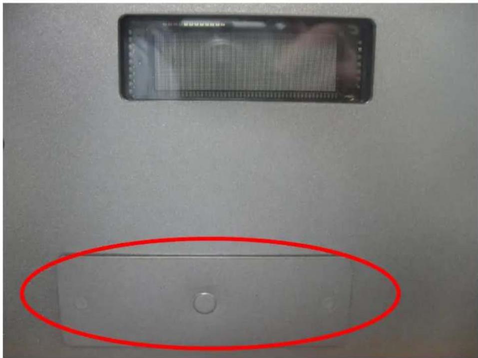
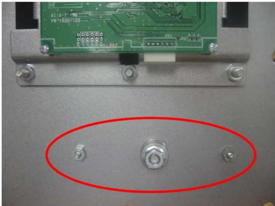
If your EVSE unit does not already have an RFID reader, open the service door and the remove the metal plate and gasket (located below the VFD) shown in Figure 31 and 32.
natural_image
Two rectangular electronic devices on a surface, one with a grid screen and the other with a red oval highlighting a transparent display (no visible text or symbols)Figure 31: Metal plate, outside view
natural_image
Close-up of a green printed circuit board with three metallic connectors and mounting screws, highlighted by a red oval (no text or symbols visible)Figure 32: Metal plate, inside view
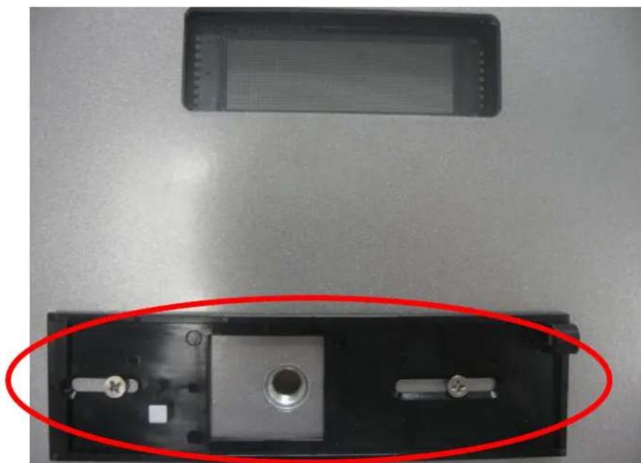
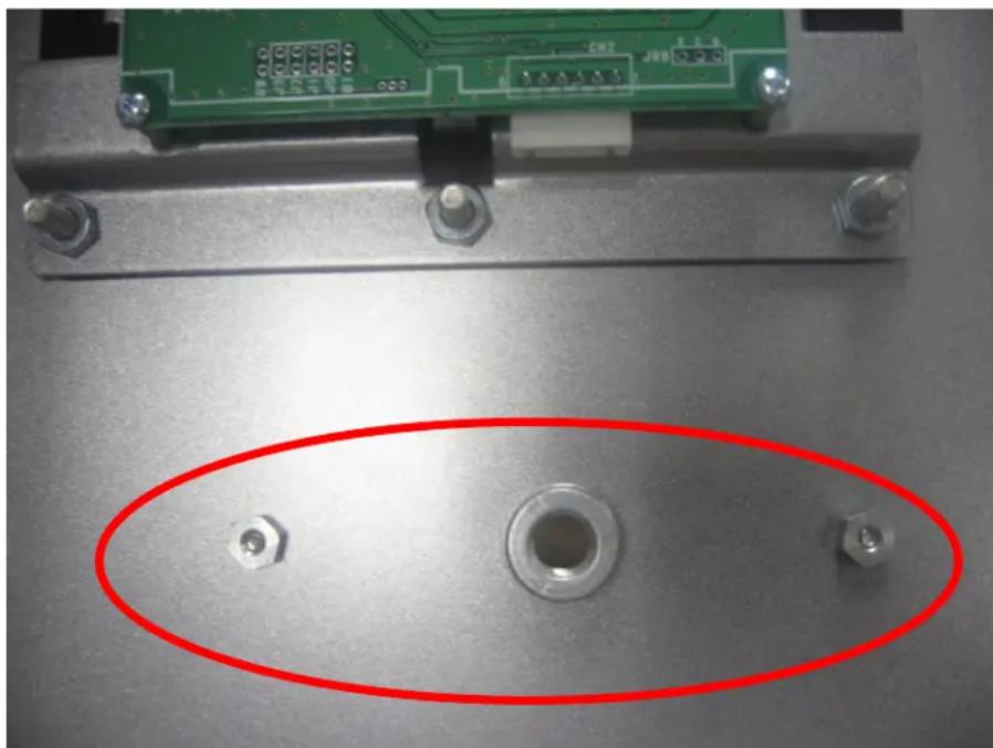
Next, attach the RFID mounting plate to the outside of the EVSE enclosure as shown in Figure 33 and 34, using the hardware provided with RFID.
natural_image
Interior view of a device showing a black case with a central hole and two metallic components, one circled in red (no text or symbols visible)Figure 33: RFID mounting plate, outside view
natural_image
Close-up of a metallic electronic component with a green circuit board and two screws, highlighting a red oval area (no text or symbols)Figure 34: RFID mounting plate, inside view
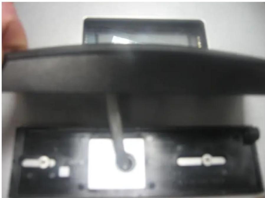
Slide the RFID cable through the open hole as shown in Figure 35, and attach the RFID to its mounting plate as shown in Figure 36 using the tamper-proof screw provided.
natural_image
Close-up of a hand holding a black electronic device with a lever inserted into a black case (no visible text or symbols)Figure 35: RFID cable
Figure 36: RFID tamper-proof screw
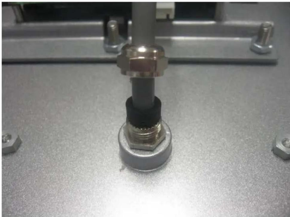
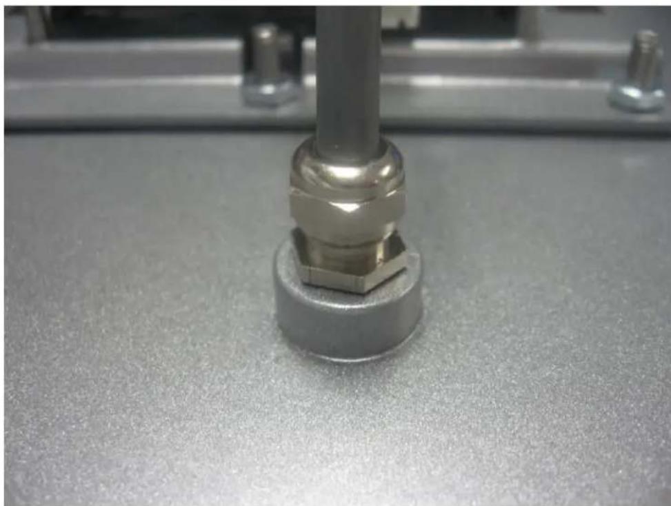
Slide the threaded gland and seal over the RFID cable from the inside of the enclosure and screw it into the threaded hole. Then slide the RFID gland nut over the cable and screw it over the seal and threaded gland. Refer to Figure 37 and 38 below.
natural_image
Close-up of a mechanical assembly with a metallic bolt and hexagonal base, no visible text or symbolsFigure 37: RFID gland assembly
natural_image
Close-up of a metallic mechanical component with hexagonal base and threaded shaft, resting on a textured surface (no visible text or symbols)Figure 38: RFID gland assembly
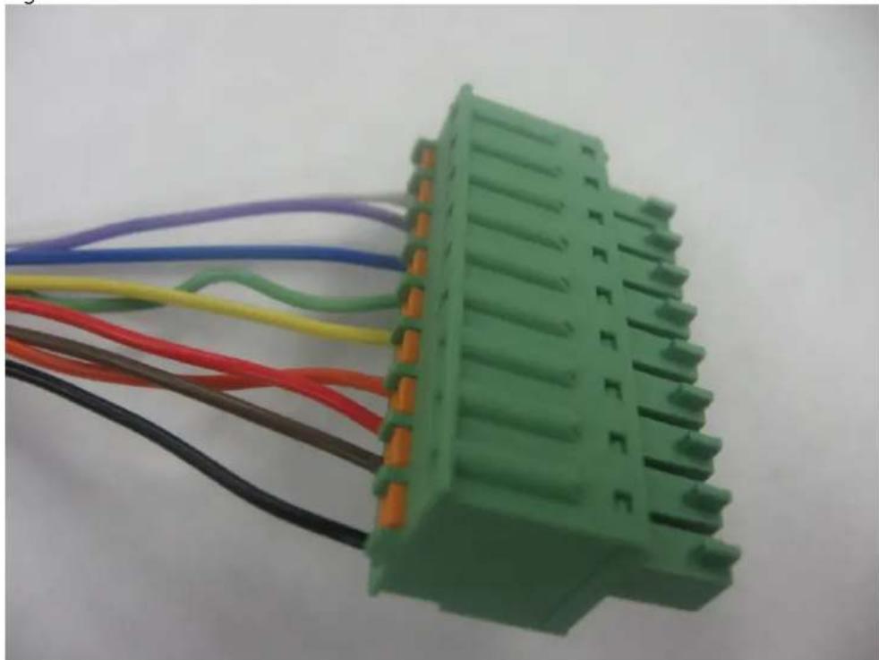
Secure the individual wires in the RFID cable inside the provided Phoenix connector, as shown in Figures 39 and 40.
natural_image
Green electrical connector with multiple colored wires attached (no visible text or symbols)Figure 39: RFID Phoenix Connector
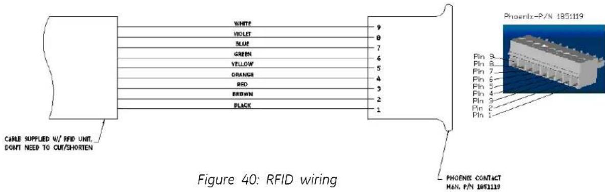
Attach the Phoenix connector to the controller in its designated location, as shown in Figure 41 and 42. Make sure to press the Phoenix collector fully into the female socket.
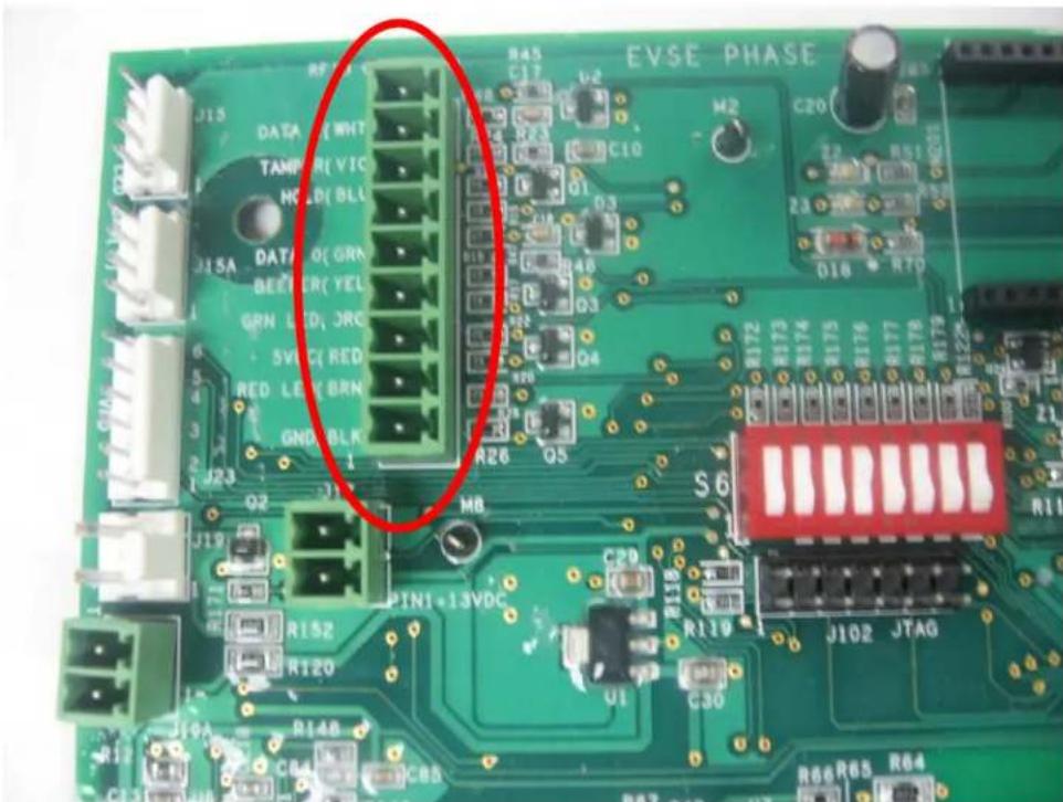
Figure 41: RFID Connection Location
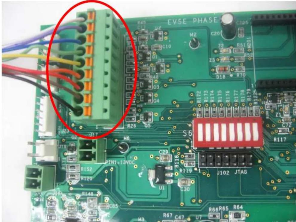
Figure 42: RFID Connection Location
Once the hardware installation is complete, refer to the software installation guide provided with the RFID package.
2.9.2 VFD

WARNING: Make sure power to the EVSE is sconnected before performing any task
This section describes how to install the VFD for Pedestal, Wall Mounted and Pole Mounted EVSE units only. For the Back to Back EVSE unit VFD replacement, contact a GE representative by calling 1-800-GE1STOP.
Open the service door and remove the VFD wire harness from the VFD as shown in Figure 43.
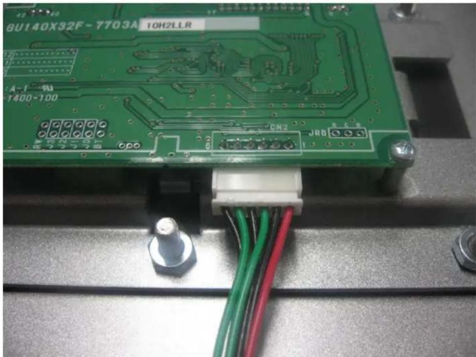
natural_image
Close-up of a green printed circuit board with visible pin labels and wiring, mounted on a metal base (no readable text or symbols beyond component identifiers)Figure 43: Harness Connection to VFD
If RFID has been provided, remove the RFID wire harness from the socket on the controller as shown in Figures 41 and 42.
Next, remove the VFD/RFID mounting assembly by removing the eight 10/32" nuts as shown in Figure 44.
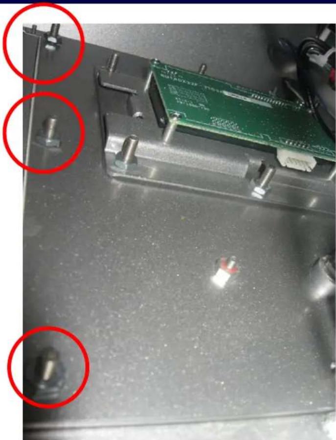
natural_image
Close-up of a green printed circuit board mounted on a metal base, with red circles highlighting specific components (no readable text or symbols)Figure 44: 3 of 8 10/32" mounting nuts displayed
Remove the RFID unit (or the metal plate and gasket if no RFID has been provided) from the VFID mounting assembly as described in Section 2.9.1.
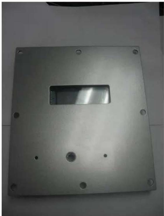
Install the new VFD/RFID mounting assembly, shown in Figure 45 and Figure 46.
natural_image
Metallic rectangular plate with a central slot and four corner holes, placed on a plain surface (no text or symbols visible)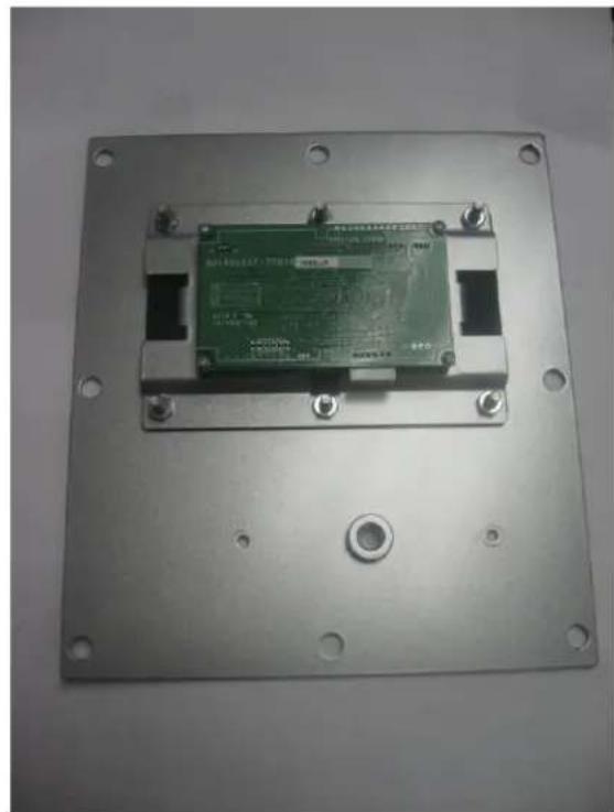
natural_image
Metallic electronic device with green circuit board mounted on a metal plate (no visible text or symbols)Figure 45: VFD/RFID mounting plate, front view Figure 46: VFD/RFID mounting plate, back view
Re-attach the RFID unit or metal plate as described in Section 2.9.1.
2.9.3 Holding Socket

WARNING: Make sure power to the EVSE is isconnected before performing any task
This section describes how to install the holding socket for Pedestal, Wall Mounted and Pole Mounted EVSE units only. For the Back to Back EVSE unit holding socket replacement, contact a GE representative by calling 1-800-GE1STOP.
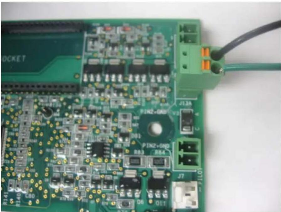
Open the service door and unplug the holding socket Phoenix connector from the controller as shown in Figure 47. Remove the holding socket wire from this Phoenix connector. The wire can be removed from the Phoenix connector by pressing in the small orange button on the connector, as shown in Figure 47.
natural_image
Close-up of a green printed circuit board with various electronic components and connectors (no readable text or symbols)Figure 47: Holding Socket Phoenix Connection
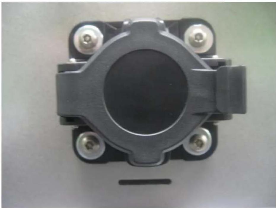
Remove the holding socket by unscrewing the four tamper-proof placement screws on the front face of the EVSE enclosure, shown in Figure 48.
natural_image
Close-up of a black mechanical component with four mounting holes and a central circular hole (no text or symbols visible)Figure 48: Holding Socket Tamper-Proof Screws
After the old holding socket is removed, insert the replacement holding socket and tighten the placement screws.
Re-connect the holding socket wire to the Phoenix connector, and re-connect the Phoenix connector to the controller.
2.9.4 Service Door

WARNING: Make sure power to the EVSE is sconnected before performing any task
Remove the service door.
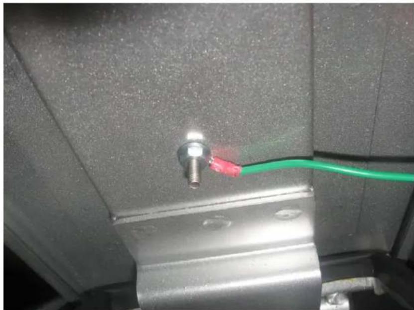
Remove the door ground wire from door ground stud, shown in Figure 49.
natural_image
Close-up of a metallic mechanical component with a green cable and red connector (no visible text or symbols)Figure 49: Door Ground Connection
Insert the new door and replace the ground wire to the door ground stud.
2.10 Wiring Diagram
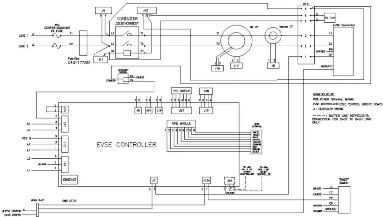
The wiring diagram shown in Figure 50 is applicable for all NEMA EVSE units and is included as a reference.
flowchart
graph TD
    subgraph Power Line
        A["LINE 1"] --> B["Ferrite 04311770B1"]
        C["LINE 2"] --> B
        B --> D["L1"]
        D --> E["L2"]
        E --> F["A2"]
        F --> G["J11"]
        G --> H["T1"]
        H --> I["T2"]
        I --> J["A1"]
        J --> K["T3"]
        K --> L["T4"]
        L --> M["T5"]
        M --> N["T6"]
        N --> O["T7"]
        O --> P["T8"]
        P --> Q["T9"]
        Q --> R["T10"]
        R --> S["T11"]
        S --> T["T12"]
        T --> U["BF CT"]
        U --> V["Isense CT"]
        V --> W["Ground"]
    end

    subgraph Control
        X["CONVER"] --> Y["AC/ULVPT SWITCH"]
        Y --> Z["RSI"]
        Z --> AA["UNI/REF"]
        AA --> AB["Ground"]
    end

    subgraph External
        AC["EVSE CONTROLLER"] --> AD["VFD DISPLAY"]
        AD --> AE["LED"]
        AE --> AF["RFID MODULE"]
        AF --> AG["RFID OFF/CONTROL"]
        AG --> AH["WHITE VOLT Blue GREEN YELLOW GRAP RED GREEN BLACK"]
        AH --> AI["TO PIN PRI 2 OF OTHER CONTROLLER"]
        AI --> AJ["TO PIN PRI 1 OF OTHER CONTROLLER"]
        AJ --> AK["UNI/REF"]
        AK --> AL["Ground"]
    end

    subgraph External
        AM["OTHERNET"] --> AN["J7"]
        AN --> AO["J13A"]
        AO --> AP["JBA"]
        AP --> AQ["JN"]
        AQ --> AR["JN"]
        AR --> AS["JN"]
    end

    subgraph Control
        AT["PTB 5"] --> AU["A2"]
        AU --> AV["L2"]
        AV --> AW["PTB 5"]
        AW --> AX["A1"]
        AX --> AY["L1"]
        AY --> AZ["L2"]
        AZ --> BA["UNI/REF"]
        BA --> BB["L1"]
        BB --> BC["Ground"]
    end

    subgraph External
        BD["INLET Socket"] --> BE["UNI/REF"]
        BE --> BF["L1"]
        BF --> BG["L2"]
        BG --> BH["PP"]
        BH --> BI["UNI/REF"]
        BI --> BJ["GROUND"]

    subgraph Control
        BK["NOMENOLATURE PTE POWER TERMINAL BOARD EVSE CONTROLLER/EVSE CONTROL CIRCUIT BOARD Δ: CUSTOMER WIRING ——: DOTTED LINE REPRESENTS CONNECTION FOR BACK TO BACK UNIT ONLY"]

    subgraph External
    BK
    end

    style External fill:#f9f,stroke:#333
    style Control fill:#ccf,stroke:#333
Figure 50: EVSE Wiring Diagram
3 User Manual
3.1 Receiving
Upon receipt of shipment, examine the package for damage that may have been sustained in transit.
If the shipping container must be opened outdoors, take proper precautions to prevent the entrance of moisture.
While unpacking, examine the product for broken, bent, or loose parts or other damage. If damage from shipment is evident, file a damage claim with the transportation company and notify the nearest sales office.
3.2 Basic User Instructions
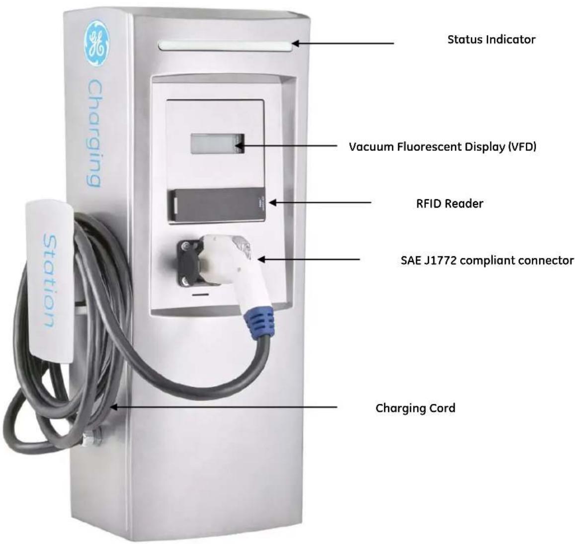
Figure 51 : EVSE Basic Features
Status Indicator:
The status indicator at the top of the EVSE displays the state of the EVSE. The key to the colors displayed on the status indicator is shown on a label directly right of the EVSE handle. The EVSE can display the following different colors:
• Green (SOLID): EVSE available for charging
- BLINKING Green: EV connected, but not energized (charging is finished or vehicle not ready for charging)
- Amber (SOLID): EV charging and connector energized
• Red (SOLID): Fault EVSE
Vacuum Fluorescent Display (VFD):
The VFD serves to prompt the user to do certain things, such as connect to vehicle or return plug to socket. It also displays useful information such as charging time and fault information.
RFID Reader
The RFID is responsible for maintaining and processing authorization of users for the EV Charging Station, and is available as an option.
When the RFID is idle, the RFID LED is red.
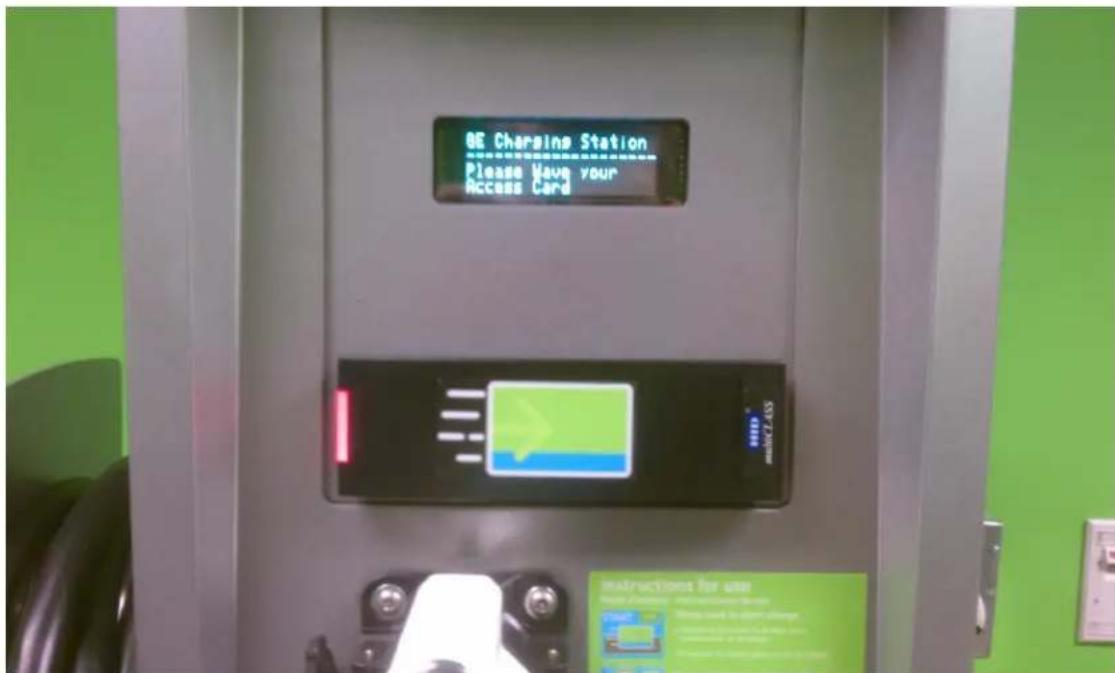
Figure 52: EVSE while idle
When the access card is waved in from of the RFID reader, it blinks green and beeps for 250 ms. See Figure 53 below.
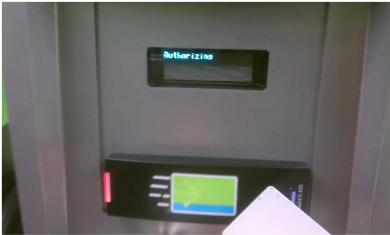
Figure 53: EVSE during card swipe
After the access card is swiped, the RFID LED returns to red until authorization is successful.
Once authorized, the RFID LED will return to green until the transaction is ended when the vehicle is disconnected.
If authorization is denied, the RFID LED remains red and the VFD will display the "denied" message.
Connecting to a Vehicle: Before connecting the EVSE to a vehicle, make sure the status indicator at the top of the EVSE is SOLID GREEN. The VFD should prompt the user to remove plug from socket and connect to vehicle. If the EVSE is displaying RED, then do not use the EVSE and contact GE technical support for assistance.
If the EVSE status indicator is SOLID GREEN, then
-
When the EVSE handle is seated in the EVSE holder, press and hold the button on the EVSE handle and pull away from the EVSE holder until it is fully removed. The VFD should prompt the user to connect cable to vehicle.
-
Press and hold the button on the EVSE handle and insert into the vehicle's inlet socket. Release the button on the EVSE handle when fully connected to the vehicle inlet socket.
Once the EVSE handle is connected to the vehicle, the status indicator will turn BLINKING GREEN or AMBER. BLINKING GREEN indicates that the vehicle is connected, but not ready to charge.
AMBER indicates that the vehicle is charging. While charging, the VFD will display the amount of charging time elapsed and total energy drawn.
Disconnect from Vehicle:
The EVSE can be disconnected from the vehicle at any time.
- Press and hold the button on top of the EVSE handle and pull the EVSE handle away from the vehicle inlet socket. The VFD will prompt to replace the handle to the EVSE holder.
- Replace the EVSE handle on the holder by pressing and holding the button the EVSE handle. Release the button when the EVSE handle is fully connected to the EVSE holder.
- The EVSE status indicator will return to SOLID GREEN once the EVSE handle has been removed from the vehicle inlet and replaced to EVSE holder.
Faults:
When the status indicator has turned RED, the EVSE is indicating a fault. There are four types of faults that can occur:
- Ground Fault
- Contactor closed when not charging Fault
- Self-Test Fault
- Overvoltage/Undervoltage Faults
- Overload fault
Ground fault:
The EVSE can detect the presence of ground faults with a threshold of 15 – 20 mA during the charging cycle. Once a ground fault is detected, the EVSE will stop charging the vehicle and the status indicator will indicate RED. If the EVSE continues to detect ground faults and the vehicle remains plugged in, the EVSE will attempt to restart charging after 15 minutes. If 4 such attempts to restart charging have occurred, the EVSE will lockout the station. The lockout will prevent any vehicle from being charged until the plug has been disconnected from the vehicle. It is highly recommended that service personnel examine the EV (electric vehicle) and/or the EVSE cable to determine the cause of the multiple faults before re-energizing.
If a ground fault is present immediately after the EVSE begins charging, the EVSE will stop charging and immediately lockout the station. The lockout will prevent any vehicle from being charged until the plug has been disconnected from the vehicle.
Contactor closed when not charging Fault:
The EVSE internally monitors itself to ensure that the EVSE is only supplying power to the EVSE handle when it is in a charging cycle. If the EVSE is supplying power to the EVSE handle in a non-charge cycle (status indicator is GREEN or FLASHING GREEN), the EVSE will lockout and the status indicator will indicate RED. The lockout will prevent any vehicle from being charged until power has been cycled on the EVSE.
Self-Test Fault:
The EVSE internally monitors its operating performance. If there is a failure of its performance, the status indicator on the EVSE will indicate RED and lockout.
Overvoltage/Undervoltage Faults:
The EVSE monitors line voltage and cuts power to the EV if the voltage goes out of range. After 1 minute the EVSE rechecks the voltage and will automatically re-enable charging if the voltage comes back within acceptable range. The status indicator will turn RED as long as charging is interrupted.
Overload Fault:
The EVSE monitors the current being drawn by the EV. If this current exceeds the capability of the EVSE fuse, charging will be interrupted and the status indicator will show turn RED. This fault can be cleared by disconnecting from the EV.
3.3 Technical Data
The GE EV Charging Station has features which provide a robust and reliable solution for the needs of EV charging infrastructure.
■ LED light to display charger status
- Option for a Radio Frequency Identification (RFID) reader: users will gain charging authorization by swiping RFID cards in front of the readers
- Ethernet network offered for RFID authorization service
- RFID software application registers usage of the EV Charging Station, enabling data collection, and will also monitor status of communication between RFID and EVSE
- Vacuum Fluorescent Display (VFD) screen showing greetings, instructions and charging station messages
■ Nuisance tripping avoidance and auto re-closure
■ Vehicle ground monitoring circuit
■ Single phase metering, displayed on VFD
Technical Characteristics
| SAE Compliant | Level II per J1772 |
| Vehicle Interface | SAE J1772 EV connector |
| Cable Length | 20' cable |
| AC Max Charging Power Output** | 7.2 kW (240VAC @ 30A) |
| Voltage and Current Rating | 208-240VAC @ 30A |
| AC Power Input | 208-240VAC requiring only Line 1, Line 2 and Earth ground |
| Short Circuit Rating | 5kA @ 240 VAC |
| Recommended Service Panel Breaker | Pole, Wall, Single Pedestal: 2-pole 40A breaker on dedicated circuit Double Pedestal: (Qty. 2) 2-pole 40A breaker on dedicated circuit |
| Ground Fault Protection | Internal 20mA CCID with auto-re-closure, does not require a GFCI in service panel |
| Cold Load Start | Random start up between 0 and 15 minutes |
| Local Area Network | CAT5 Ethernet |
| Network Communication Protocol | TCP/IP |
| Network Security | GE recommends that network be VPN and Firewall protected |
| Metering Accuracy | 2% accurate on voltage and current; 4% accurate on power and energy |
| RFID Reader | ISO15693 compliant |
| Display Screen | Vacuum Fluorescent Display |
| Standby Power | 5W typ. |
| Indoor Ventilation | Signal provided to turn on facility fans |
| Outdoor Rated | Enclosure NEMA 3R |
| Safety Compliance | UL 2231, UL 2251, UL 2594, cUL 2231, cUL 2594, NEC 625, SAE J1772 |
| Surge Protection | 6kV @ 3000A |
| EMI Compliance | FCC Part 15 Class A |
| Operating Temperature | -30°C to +50°C ambient |
| Operating Humidity | Up to 95% non-condensing |
| Approximate Shipping Weights | Single Pedestal: 120 lbSingle Pedestal: 160 lbPole: 75 lbWall: 75 lb |
| Dimensions | Single Pedestal: 57.6"H x 18.4"W x 20.9"DDouble Pedestal: 57.6"H x 18.4"W x 28"DWall: 31.5"H x 14.9"W x 11.2"DPole: 31.5"H x 14.9"W x 11.2"D |
- Table 10 -
**The maximum power consumption is determined by EVSE. The actual power consumption is determined by EV.
Family Catalog
| Type | Enclosure | Output | No. of Connectors | Single Phase Integrated Meter | RFID | Cat # |
| Single Pedestal | NEMA 3R | 208-240V 30A 1 phase | 1 | Yes | No | EVSN3 |
| Yes | EVSRN3 | |||||
| Double Pedestal | NEMA 3R | 208-240V 30A 1 phase | 2 | Yes | No | EVDN3 |
| Yes | EVDRN3 | |||||
| Pole | NEMA 3R | 208-240V 30A 1 phase | 1 | Yes | No | EVPN3 |
| Yes | EVPRN3 | |||||
| Wall | NEMA 3R | 208-240V 30A 1 phase | 1 | Yes | No | EVWN3 |
| Yes | EVWRN3 |
- Table 11 -
3.4 Additional Considerations
Physical Security
Physical security is a necessary consideration in any installation of this type. There should be physical controls to reduce the probability of a malicious entity's chances of gaining access to any area of the system. Network, maintenance access and power connections should be secured with strong physical controls, i.e. all connections behind an access panel or door with a keyed lock to limit access. This door or access panel should be strong (metal as a suggestion) and the lock should be of a type that is not commonly available to the general public.
All wiring should be enclosed in conduit meeting the local electrical and communications building codes. And all conduits should firmly attach to the secured "box" where communications would be terminated within the Charging Station.
3.5 EVSE Controller Settings
3.5.1 Configuration Switch Settings
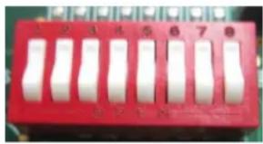
Using the configuration dip-switch S6, the controller can be placed into the desired operational mode.
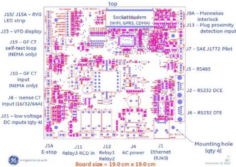
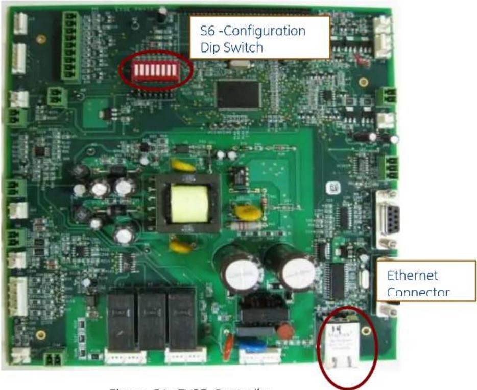
Figure 54: EVSE Controller
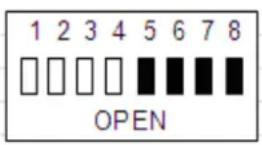
The configuration dip switch has positions 1 thru 8. Switches 1 to 4 are set and locked by the manufacturer, and switch 5 is reserved for future use. Switches 6, 7 and 8 are set at installation of the EVSE into its operational environment.
natural_image
Red rectangular electronic component with eight white ceramic pins arranged in a grid (no visible text or symbols)Pushed down on "number" side is the CLOSED position
Figure 55: Dip Switch Settings
(This picture depicts an example of all CLOSED dip switch positions. For correct settings, refer to below tables)
The default settings per SKU are given in below table:
| 1 | 2 | 3 | 4 | 5 | 6 | 7 | 8 |
| Factory setting | Factory setting | Factory setting | Factory setting | reserved | Language settings | Config. server | |
| CLOSED | CLOSED | CLOSED | OPEN | CLOSED | OPEN *) | OPEN *) | CLOSE **) |
*) Language Settings
| 6 position | 7 position | |
| No Display or Set Language Via Config. Server | Close | Close |
| Spanish | Close | Open |
| French | Open | Close |
| English | Open | Open |
**) Configuration Server
CLOSE = Normal operation
OPEN = Configuration server
3.5.2 Display fault messages
EVSE controller is capable of providing a full range of Fault troubleshooting options. When the controller experiences a fault it will display the brief fault description message as well as the specific fault code on the display.
Fault codes:
0x00000001
Fault indicating that the unit has experienced a ground fault and is waiting the required amount of time (15 minutes) before it attempts to reclose the main contactor, clear the fault and continue charging.
0x00000002
Fault indicating that the controller has experienced the maximum allowed number of ground faults for a charge cycle.. To reset this fault simply disconnect the EVSE plug from the vehicle, and wait for at least 30 seconds.
0x00000004
Fault indicating that the unit has experienced a Ground fault CT test failure, either during the power-up self-test or during charge cycle initialization self-test. Check the ground fault CT (current transformer), connections or the EVSE controller. Disconnecting from the vehicle will clear this fault. If it persists repeatedly the ground fault CT and EVSE controller circuit need to be checked.
0x00000008
Fault indicates that the EVSE controller has detected that the vehicle is drawing excessive current during the charge cycle so it has interrupted charging. To clear this fault, disconnect the EVSE plug from the vehicle.
0x00000010
Fault indicating that the unit E-stop jumper (J14 or J14A) is not installed. Check/install connector J14 or J14A on the controller.
0x00000020
Unit has failed a Pilot Diode self-test required per the SAEJ1772 / IEC 61851 standard. This is a feature which prevents tampering with the controller and the interlock connector. To clear this fault, disconnect from the vehicle and repeat. If fault persists, there is likely a problem with the vehicle's pilot interface.
0x00000040
Indicates an illegal Pilot transition state detected by the controller from the vehicle. This condition will automatically clear when the pilot returns to an appropriate state. Note: some vehicles may not comply with the SAE J1772 / IEC 61851 standard and go directly from state A to state C. To accommodate charging of such vehicles, use the non-SAE compliant configuration setting on the configuration menu (see Section 3.4.4 NON-SAEJ1772 configuration).
0x00000080
Controller has experienced 0V state feedback from the Vehicle which is an illegal state and it indicates an error from the vehicle. The fault will clear upon disconnection from the vehicle.
0x00000100
Controller has experienced an unknown Pilot voltage level during power up which is not compliant to the SAEJ1772 / IEC 61851 standard. This fault can only be cleared by cycling power to the EVSE. If this error persists, the EVSE needs to be serviced.
0x00000200
Controller is not detecting feedback from the Main contactor Aux. Connections at J11. Check for connections per the System level wiring diagram or a hardware fault with the contactor or the controller. This fault is cleared by disconnection of the EVSE plug from the vehicle.
0x00000400
Indicates an incorrect hardware configuration. Ensure that the controller is placed in the correct desired configuration using the Dip Switch (S6) and properly installed into the system. This fault can only be cleared by cycling power to the EVSE.
0x00001000
Controller has detected that the contactor is still in Closed state after the controller issued a command to open the contactor. Check the Main contactor, system wiring or the controller. This fault can only be cleared by cycling power to the EVSE. With power removed, examine the contactor, the auxiliary feedback circuits, and the connections at J11.
0x00004000
Non-volatile memory (NVM) is used to store configuration settings and data which needs to be retained during power outages. The controller has detected an issue with NVM. Cycle power to the EVSE controller to attempt fault recovery. If fault persist, redefine the configuration settings by running the configuration server. Call service if repeating configuration set up does not clear the fault."
0x00008000
Controller has detected an Over voltage condition at the input supply voltage which exceeds the allowed range for EV charging. Recovery is automatic when the voltage returns to an appropriate range. There is a one minute delay before reclosing to prevent the possibility of contactor chattering for unstable line voltage conditions.
0x00010000
Controller has detected an Under voltage condition at the input supply voltage which is below the allowed range for EV charging. Recovery is automatic when the voltage returns to an appropriate range. There is a one minute delay before reclosing to prevent the possibility of contactor chattering for unstable line voltage conditions.
0x00040000
Controller has detected an out of range ambient temperature condition. To clear this fault the power must be removed and reapplied to the EVSE. If this error persists, the EVSE needs to be serviced.
0x00080000
Controller has detected an internal operation error and will require servicing. To clear this fault the AC voltage must be removed and reapplied to repeat the test. Repeated occurrence of this fault indicates need for a replacement control board.
0x00200000
The controller contains an IC (integrated circuit) which stores the globally unique MAC address which is required for the Ethernet operations. If the controller is not able to read this address it will set this fault. To clear and reattempt to read the MAC address, power to the EVSE must be removed and reapplied. Repeated occurrence of this fault indicates need for a replacement control board.
4 Network Setup Instructions
This chapter details design recommendations for a GE EV Charging Station Network Infrastructure. Network setup is required for installations that use RFID authentication. It is not required for EVSE that do not use RFID authentication.
This section of the installation document covers the options for connecting the charging stations with a PC hosting the EV100 GE EV Charging Station Manager Application software.
4.1 Definitions and Terms
Certain terms are used throughout this chapter; in order to avoid misinterpretation, several of the more commonly used terms are defined below.
o CS: Charging Station. These are individual units that provide electrical charging services to vehicle at a time. (Double pedestal provides charging to two)
○ Host System/Host PC: The PC that runs the GE EV Charging Station Manager Application to manage authorization and collect data from the Charging Stations.
o Firewall: A network security device that provides controlled access between two or more network segments, denying anything except approved communications between the various network segments.
- DMZ: Demilitarized Zone. An isolated network segment attached to a separate connection point on a firewall. This segment is then granted specific access to or from any other "Zone" to control who/what can connect INTO the DMZ or what the system or systems within the DMZ can connect OUT to.
○ Switch: A network device that provides multiple connection points for attaching devices to an individual segment of a communications network. For the purpose of this document, they are Ethernet network switches.
o NIC: Network Interface Card. A PC card with an RJ45 port that provides Ethernet connectivity.
○ Service laptop or PC: A laptop or PC used to configure individual EVSE stations via direct Ethernet connection (use a cross-connected cable)
4.2 Firewall and Security Considerations
- Firewall.
Any firewall used to provide isolation from the charging station network to any other network should, at a minimum, provide "Statefull Packet Inspection".
Anything less would not provide acceptable security and protection. SOHO firewalls are available that provide this capability but there are some which do not.
Any firewall used for a DMZ environment should be a business class system (i.e. Cisco ASA, Checkpoint, SonicWall, etc) and provide a true DMZ capability. Typical SOHO firewalls do NOT provide true DMZ capabilities.
GE supports the use of the Cisco ASA5505 firewall and provides settings for its use in this scenario.
- Physical Security.
Physical security is a necessary consideration in any installation of this type. There should be physical controls to reduce the probability of a malicious entity's chances of gaining access to any area of the system.
Network, maintenance access and power connections should be secured with strong physical controls, i.e. all connections behind an access panel or door with a keyed lock to limit access. This door or access panel should be strong (metal as a suggestion) and the lock should be of a type that is not commonly available to the general public.
All wiring should be enclosed in conduit meeting the local electrical and communications building codes. And all conduits should firmly attach to the secured "box" where communications would be terminated within the Charging Station.
4.3 Controller Configuration
4.3.1 Introduction
The Configuration Server Interface is used to make modifications to the network settings and to certain operation parameters of the charging station controller. The controller will boot into a default configuration. The network defaults will need to be changed in order to accommodate the decisions in choosing the stand-alone or fire-walled configuration and to avoid conflicts with the installation of subsequent controllers.
Each EVSE needs to be configured individually using a service PC or laptop during the installation and setup of the controllers.
4.3.2 Prepare Service Laptop or PC
In order to set up your service laptop or PC, make sure you have full Windows Administrator rights. Disable any firewalls and all other Ethernet and WiFi connections for the duration of the setup.
Make sure no EVSE is connected or at least not powered during these setup changes.
Then follow these steps to configure your TCP/IP settings for communication with the EVSE during setup.
After the setup, you may want to set them back to your normal settings by undoing the same steps, enable WiFi connections and firewalls.
- Open the network settings by going to Start > Control Panel > Network connections.
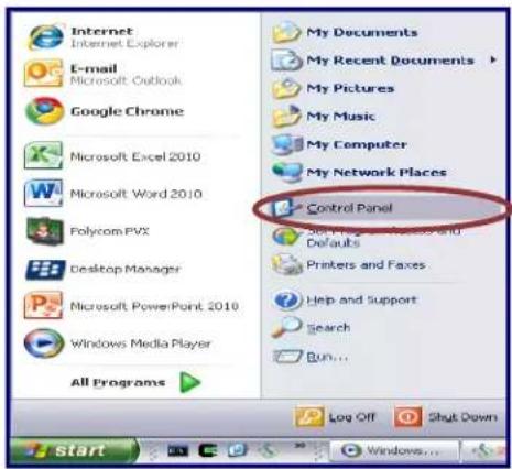
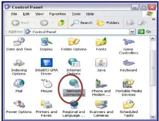
Figure 56
- Right Click on Local Area Network and select to open the properties Window
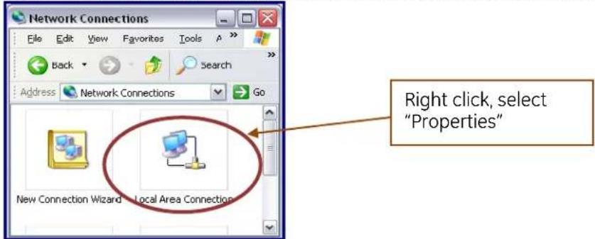
Figure 57
- Scroll through the protocols used by the local area connection to find the Internet Protocol (TCP/IP). Select this protocol by clicking on it and then click on the Properties button to open the window that will allow you to set the IP address and Subnet mask.
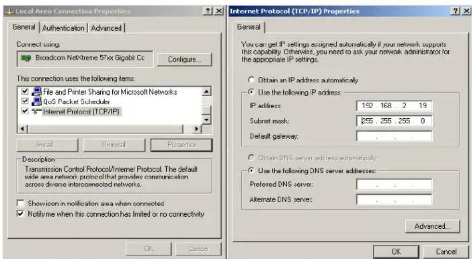
Figure 58: TCP/IP settings on the test PC
- Click the Radio button to "Use the following IP Address" and then enter both the IP address and Subnet mask as shown.
| IP Address | 192.168.2.19 |
| Subnet Mask | 255.255.255.0 |
| Default Gateway | Leave Blank |
- Click OK and Close both properties windows to save your settings
\*Note:
Proxy Settings
In Internet Explorer, open "Tools">Internet Options", click on "Connections" tab and then "LAN Settings":
- Enable "Use automatic configuration script".
- Disable "Automatically detect settings" and "Use a proxy server for your LAN" as shown.
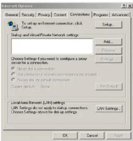
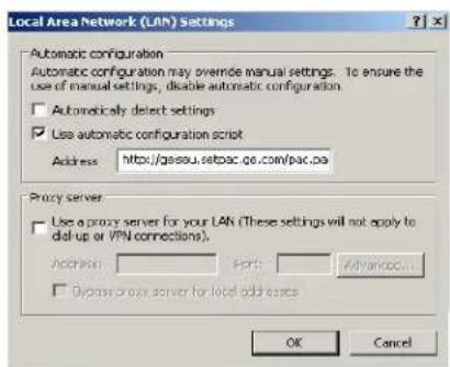
Figure 59: LAN settings
4.3.3 EVSE Configuration Server Interface
This paragraph describes how to access the EVSE controller Configuration Server Interface and which settings can be made.
In a networked environment, each EVSE needs to be configured according to the instructions given in this document, and depending on the type of network chosen.

CAUTION: when manipulating the EVSE, always make sure the power to the EVSE is switched before coming close or touching any parts of the interior.
To configure each individual EVSE
-
Switch off EVSE main Circuit Breaker (Removing power from the EVSE). Connect the Ethernet test cable to the EVSE controller Ethernet port J1 and the other end to the service laptop Ethernet connector.
-
It is recommended to use a crossed Ethernet cable for direct connectivity between the EVSE and the service laptop or PC.
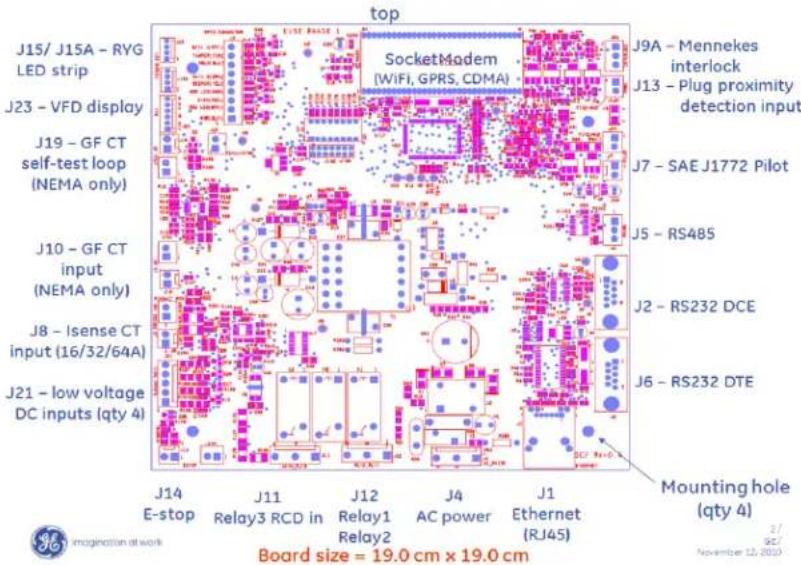
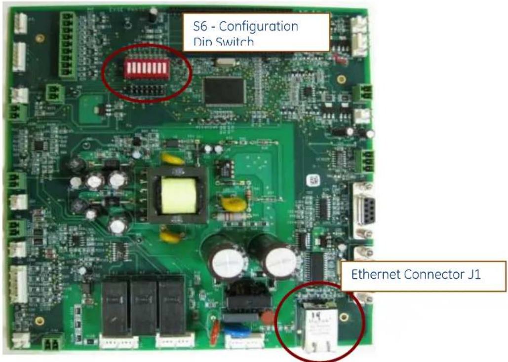
Figure 60: EVSE Controller
- With the power removed, change the position of switch 8 on the S6 to:
Switch 8 - Open (Configuration server interface)
Keep the other switches in their original position.
This Dip-Switch configuration will enable the maintenance interface used during the initial installation of the EVSE.
- Switch on EVSE main Circuit Breaker to power up the EVSE in configuration mode
a. As long as the Ethernet connection is not active, the EVSE's light is red.
b. As soon as the Ethernet connection is established, You should see the EVSE's light continuously go through a sequence of colors (green – yellow – red), each for 5 seconds to indicate that the unit is in configuration mode.
Note that as long as the Ethernet connection is not active, the EVSE's light is red.
-
Make sure the service laptop or PC has been configured as explained in a previous chapter.
-
Check that the LAN connection is established to the service laptop or PC (Status "Connected")
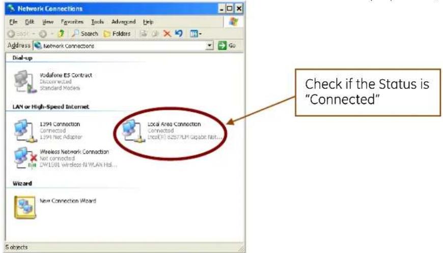
Figure 61
- On the service PC or laptop, open a browser window and type in the address bar the following address and press enter: http://192.168.2.2
Note: Should the EVSE in question previously have been assigned a different default EVSE IP address, enter here that IP address.
Note: If you have forgotten the IP address of this EVSE, reset the controller.
7. The Controller will invoke the following page:
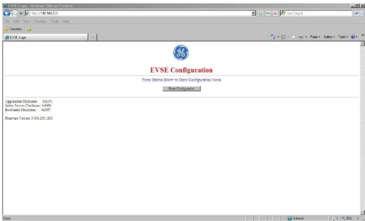
Figure 62: Configuration Server Entry Screen
- Pressing the Enter Configuration button, the following page will load:
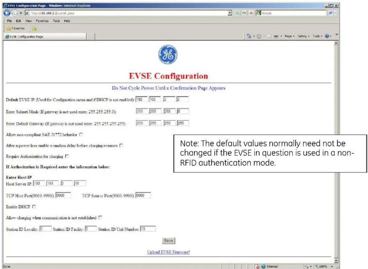
Figure 63: Configuration server page with factory default values
- In the EVSE configuration page modify settings as required.
The correct settings depend on the chosen network architecture and are described in a later chapter in detail.
There are 3 options for configuration:
■ No RFID Authentication (default)
■ RFID authentication in standalone network (see later chapter)
- RFID authentication in firewalled network (see later chapter)
After the desired settings were configured click on "Save". The following page will load:
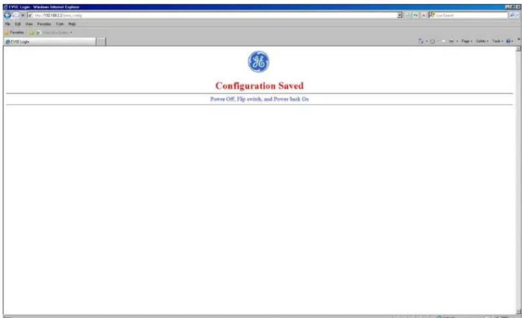
Figure 64: Configuration Server Confirmation Page
- Close the browser page and remove power to the EVSE controller.
- Change the position of the S6 Dip-switch back to:
■ Switch 8- Closed (Normal operation)
Keep the other switches in their previous positions.
This Dip-Switch configuration will enable the normal operation of the EVSE controller after powered up.
4.4 Recommended Network Designs for RFID Authentication
It is strongly recommended using one of below network settings, as those are providing necessary security levels for the Charging Station System network and other parts of the network.
4.4.1 Option 1: Stand-alone Network Configuration
In this design the charging station network and its associated host system are not connected to the customer network at all. Optional remote service access to the host system is via a dial-up modem only.
This provides the greatest protection to the customer network, as there is no communication between the customer network and the charging station network.
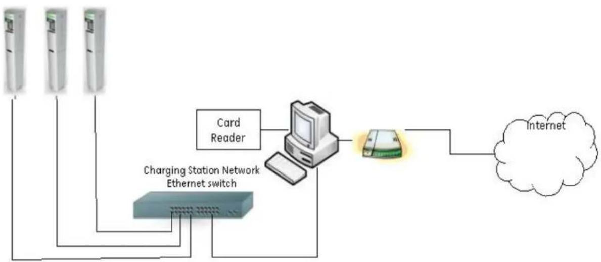
flowchart
graph TD
    A["Card Reader"] --> B["Computer"]
    C["Charging Station Network Ethernet switch"] --> B
    B --> D["Internet"]
    style A fill:#f9f,stroke:#333
    style C fill:#f9f,stroke:#333
    style D fill:#ccf,stroke:#333
Figure 65: Network Setup Option 1 – Standalone Configuration
Required Components:
- Host Application PC
— Cat 5 Network Cables - Ethernet Switch
- Optional Modem (for remote service only, otherwise not required)
- Card reader, accessory from GE catalogue # EVRP01 (Note: only GE enrollment readers work with this application)
EVSE Controller Settings
Follow the instructions in the Controller Configuration section to set up each individual EVSE according to the following settings:
• EVSE IP
Action required!
On initial power up the EVSE IP address will default to 192.168.2.2 This must be changed to an appropriate address based on the network configuration. Failure to change the IP address setting will impact the ability to bring up subsequent charging stations on the network due to IP address collisions.
Assign IP addresses to the charging stations beginning with 192.168.2.22.
As additional charging stations are added increment the last octet, so that they are numbered in consecutive numbers. (192.168.2.22, 192.168.2.23, 192.168.2.24, and so on).
All of the charging stations will use the same subnet mask 255.255.255.0 with the default gateway setting as 0.0.0.0 (blank).
Note: It is recommended to keep track of the different IP settings for each EVSE by recording them on the form found on the final page of this document.
- Subnet Mask
Set the Subnet Mask to 255.255.255.0
Default Gateway
Set the gateway to 0.0.0.0 (blank)
• Fan wired with contactor
EVSE owners with indoor installations who want to charge vehicles that require facility fans to be turned on must run signal connections to terminals 4 and 5 of the Power Terminal Block (PTB). The EVSE owner must follow electrical codes to ensure that proper ventilation is allocated for their facility.
• Non-compliant SAEJ1772 behavior
Some earlier EV models equipped with a retrofit kit have a Pilot signal feedback that does not comply with the SAE-J1772 / IEC 61851 standard. By default, this option is not enabled. Should there be cars with retrofit kits to use this EVSE, check this box.
After a power loss enable a random delay before charging resumes
If there is a large number of EVSE on a local feed, consider setting this box to enable a gradual increase in load on resumption of power.
- Require Authorization for charging.
RFID authentication requires this check box to be checked on all EVSE in the network.
Action required!
Action required!
Note: In the case of any modification of the "Require authentication for charging" status, or after a reset or replacement of the controller, the Station ID must be modified to a new ID not previously used on this network to avoid transaction data to be lost.
- Host IP address.
By default, the IP address is set to 192.168.2.19. Unless there is a collision with another setup, it is recommended to keep this host address.
Should this address change, the network PC will need to be configured accordingly in the TCP/IP settings, as explained later below.
- TCP Host Port & TCP Source Port.
Action required!
Change the value to 9500 for both the Host and Source Port to match the default value of the EV100 Application SW. Unless there is a collision by using this Port on the host PC, it is recommended to configure the EV100 application to use port 9500 (by default) and all EVSE in the network to also use port 9500 (factory default is 9000).
Note: The port number on all EVSE in the network must match the port number defined during the EV100 Software installation.
- Enable DHCP
Keep this option disabled at any time.
- Allow charging if communication is not established
By default, this option is not selected. Checking this box will modify the behavior of the EVSE in the case of network loss:
If unchecked, the EVSE will not allow charging of a car in the case of network communication failure between the EVSE and the Host PC.
If checked, the EVSE will allow charging of a car despite of a network communication failure.
- Station ID information
Action required!
Fill in the Station ID information to distinguish EVSE from each other in the EV100 Application. It is important to give each EVSE a unique ID.
IDs will appear in the EV100 Application in the format "1-12-9" (e.g. Locality ID = 1, Facility ID = 12, Unit number = 9).
Note: The Station ID information is how the EV100 application distinguishes between stations in the same network. Make sure you assign different values to each EVSE.
Note: In the case of any modification of the "Require authentication for charging" status, or after a reset or replacement of the controller, the Station ID must be modified to a new ID not previously used on this network to avoid transaction data to be lost.
After the desired settings were configured click on "Save".
Repeat this procedure for all EVSE in the network.
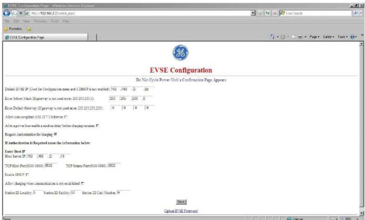
Figure 66
Host PC Settings
In order to set up your Host PC, make sure you have full Windows Administrator rights. Disable any firewalls and all other Ethernet and WiFi connections on this PC.
Then follow these steps to configure your TCP/IP settings for communication with the EVSE during setup.
The NIC on the host PC should be connected to the Charging Station Network Ethernet Switch.
To configure the network settings on a PC running Windows XP or Windows 7, press the Start button and open the Control Panel. Select the Network Connections applet.
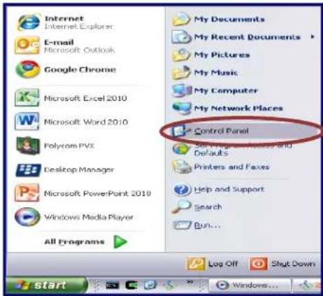
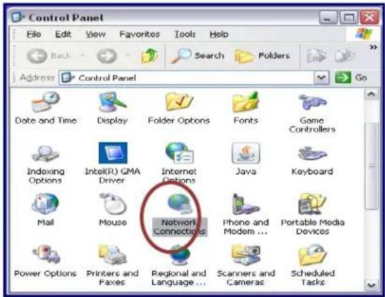
Figure 67: Network Connections
This displays the connections currently found on the PC. Select the icon for the Local Area Connection and double click to open the properties for this NIC.
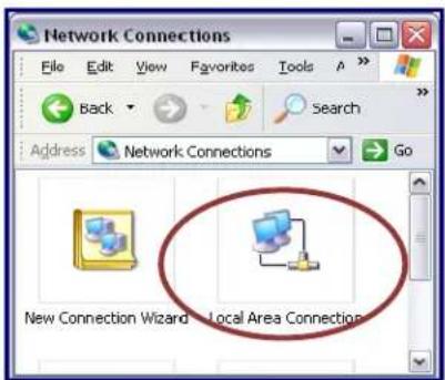
Figure 68: LAN Network Connection
Scroll through the protocols used by the local area connection to find the Internet Protocol (TCP/IP). Select this protocol by clicking on it and then click on the Properties button to open the window that will allow you to set the IP address and Subnet mask.
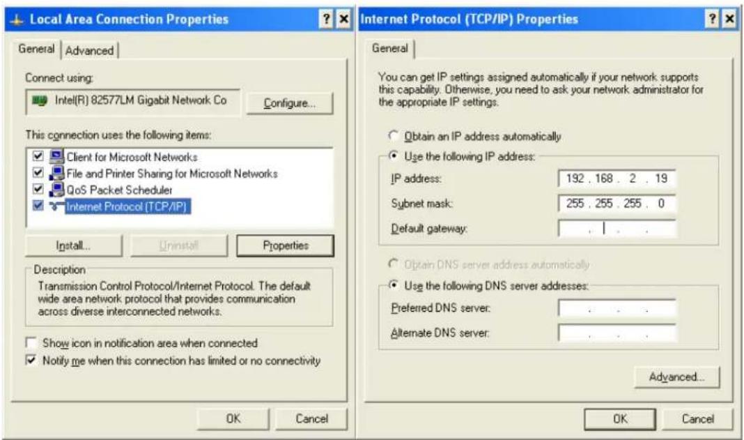
Figure 69: Network Settings Option 1 (See the Configuration Server Interface section)
Click the Radio button to "Use the following IP Address" and then enter both the IP address and Subnet mask as shown.
Set the Ethernet IP address, Subnet Mask, and Default Gateway to the following settings:
| Host IP Address | 192.168.2.19 |
| Host Subnet Mask | 255.255.255.0 |
| Host Default Gateway | Leave Blank |
Click on OK and close both windows to save your settings.
Note: The IP address above must match the Host IP address entered in the configuration page of all connected EVSE. By default, this is 192.168.2.19.
Note: Reboot PC to finalize with the configuration.
4.4.2 Option 2: Charging Station Network isolated from Customer Network with Host System in a DMZ.
In this design, the charging stations are isolated from the customer network and the host system is within a DMZ providing isolation from BOTH the Charging Station Network AND the Customer Network. This minimizes the risks of someone compromising the charging station network or the host system and using either to compromise or gain access to the customer network.
The host system is within a DMZ providing isolation from both the charging station network and the customer network and communicates with the charging stations via a rule or access control list entry which allows communications between ONLY the host system and the charging stations. A rule or rules would be established to permit specific systems on the customer network to access the host system.
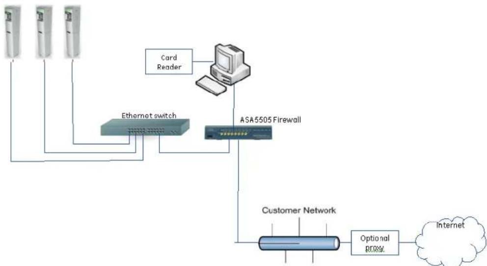
flowchart
graph TD
    A["Card Reader"] --> B["ASA 5505 Firewall"]
    C["Ethernet switch"] --> B
    D["Internet"] --> E["Optional R/OXV"]
    B --> F["Customer Network"]
    F --> E
Figure 70: Network Setup Option 2 -Networked Configuration with DMZ
This provides greater protection and isolation than the previous designs in this document. It's not perfect as the charging stations need to initiate some of the communications to the host system, so a rule or ACL will have to be in place on the firewall to allow this communications. But it also isolates that communications from the customer network. A properly configured firewall will provide greatly enhanced protection to the customer network.
Required Components:
- Host Application PC
— Cat 5 Network Cables - Ethernet Switch
— ASA5505 security plus firewall - Card reader, accessory from GE catalogue # EVRP01 (Note: only GE enrollment readers work with this application)
EVSE Controller Settings
Follow the instructions in the Controller Configuration section to set up each individual EVSE according to the following settings:
• EVSE IP
Action required!
On initial power up the EVSE IP address will default to 192.168.2.2 This must be changed to an appropriate address based on the network configuration. Failure to change the IP address setting will impact the ability to bring up subsequent charging stations on the network due to IP address collisions.
Check with the local network administrator to determine which address ranges are currently in use at the site.
It is necessary to select ranges for the charging stations that are distinct from those currently in use to avoid IP address conflicts.
If the 172.25.x.x. range is not in use the following settings should be implemented.
Set the EVSE Ethernet IP address, Subnet Mask, and Default Gateway to the following settings:
| EVSE IP Address | 172.25.0.xx |
| EVSE Subnet Mask | 255.255.255.0 |
| EVSE Default Gateway | 172.25.0.1 |
Assign IP addresses to the charging stations beginning with 172.25.0.12. As additional charging stations are added increment the last octet, so that they are numbered in consecutive numbers starting from 12. (Examples: 172.25.0.12, 172.25.0.13, 172.25.0.14, and so on). All of the charging stations will use the same subnet mask 255.255.255.0 with the default gateway set to 172.25.0.1
Alternatively, if that range is in use, on the assumption that the 172.26.0.x. range is available use these alternate settings:
| EVSE IP Address | 172.26.0.xx |
| EVSE Subnet Mask | 255.255.255.0 |
| EVSE Default Gateway | 172.26.0.1 |
This alternate setting will require the assignment of IP addresses to the charging stations beginning with 172.26.0.12 As additional charging stations are added increment the last octet, so that they are numbered as for example: 172.26.0.12, 172.26.0.13, 172.26.0.14, and so on. All of the charging stations will use the same subnet mask 255.255.255.0 with the default gateway set to 172.26.0.1.
Note: It is recommended to keep track of the different IP settings for each EVSE by recording them on the form found on the final page of this document.
- Subnet Mask
See above
Default Gateway
See above
- Fan wired with contactor
EVSE owners with indoor installations who want to charge vehicles that require facility fans to be turned on must run signal connections to terminals 4 and 5 of the Power Terminal Block (PTB). The EVSE owner must follow electrical codes to ensure that proper ventilation is allocated for their facility.
• Non-compliant SAEJ1772 behavior
Some earlier EV models equipped with a retrofit kit have a Pilot signal feedback that does not comply with the SAE-J1772 / IEC 61851 standard. By default, this option is not enabled. Should there be cars with retrofit kits to use this EVSE, check this box.
After a power loss enable a random delay before charging resumes
If there is a large number of EVSE on a local feed, consider setting this box to enable a gradual increase in load on resumption of power.
- Require Authorization for charging.
RFID authentication requires this check box to be checked on all EVSE in the network.
Action required!
Note: In the case of any modification of the "Require authentication for charging" status, or after a reset or replacement of the controller, the Station ID must be modified to a new ID not previously used on this network to avoid transaction data to be lost.
- Host IP address
Action required!
By default, the IP address is set to 192.168.2.19, and needs to be changed to one of the following options, depending on which address range to use:
- 172.25.1.100 in case of the EVSE IP range being 172.25.0.xx
- 172.26.1.100 in case of the EVSE IP range being 172.26.0.xx
Note: Make sure the Host PC is configured according to the same IP address settings as entered in the EVSE configuration server page.
• TCP Host Port & TCP Source Port.
Action required!
Change the value to 9500 for both the Host and Source Port to match the default value fo the EV100 Application SW. Unless there is a collision by using this Port on the host PC, it is
recommended to configure the EV100 application to use port 9500 (by default) and all EVSE in the network to also use port 9500 (factory default is 9000).
Note: The port number on all EVSE in the network must match the port number defined during the EV100 Software installation.
- Enable DHCP
Keep this option disabled at any time.
- Allow charging if communication is not established
By default, this option is not selected. Checking this box will modify the behavior of the EVSE in the case of network loss:
If unchecked, the EVSE will not allow charging of a car in the case of network communication failure between the EVSE and the Host PC.
If checked, the EVSE will allow charging of a car despite of a network communication failure.
- Station ID information
Action required!
Fill in the Station ID information to distinguish EVSE from each other in the EV100 Application. It is important to give each EVSE a unique ID.
IDs will appear in the EV100 Application in the format "1-12-9" (e.g. Locality ID = 1, Facility ID = 12, Unit number = 9).
Note: The Station ID information is how the EV100 application distinguishes between stations in the same network. Make sure you assign different values to each EVSE.
Note: In the case of any modification of the "Require authentication for charging" status, or after a reset or replacement of the controller, the Station ID must be modified to a new ID not previously used on this network to avoid transaction data to be lost.
After the desired settings were configured click on "Save".
Repeat this procedure for all EVSE in the network.
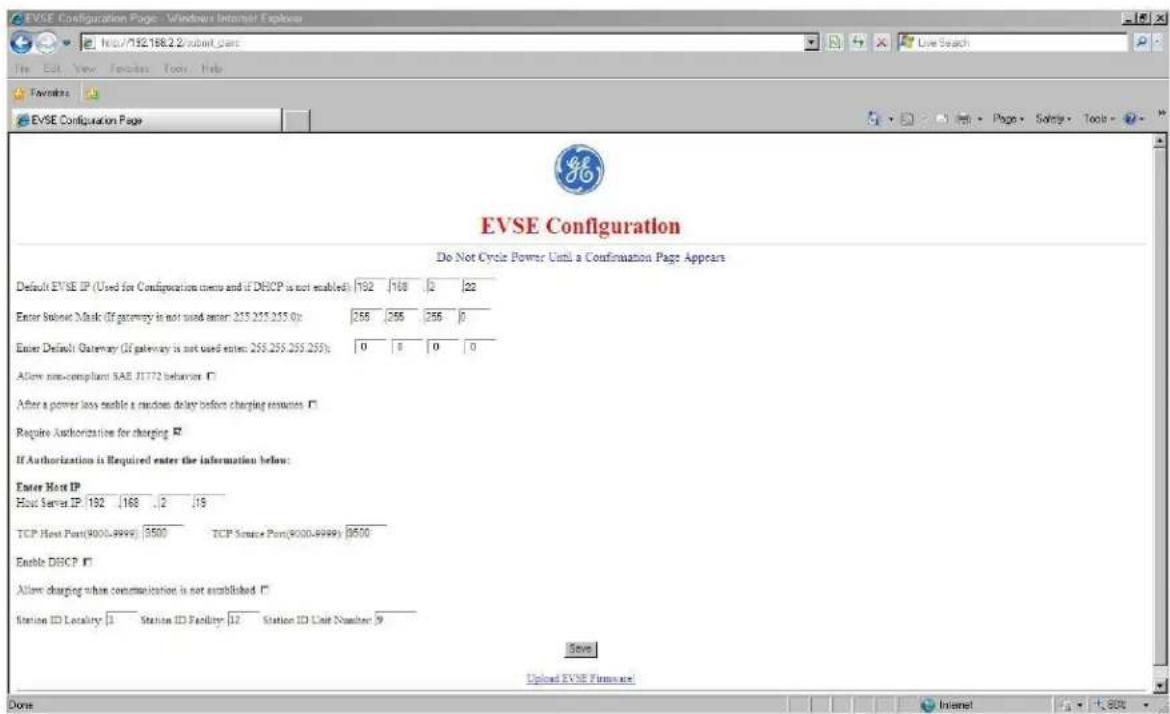
Figure 71
Host PC Settings:
In order to set up your Host PC, make sure you have full Windows Administrator rights. Disable any firewalls and all other Ethernet and WiFi connections on this PC.
Then follow these steps to configure your TCP/IP settings for communication with the EVSE.
The NIC on the host PC should be connected to the ASA5505 firewall port number 0/6. A network cable connects port 0/0 on the firewall to port 1 on the Charging Station Network Ethernet Switch.
To configure the network settings on a PC running Windows XP Press the Start button and open the Control Panel. Select the Network Connections applet.
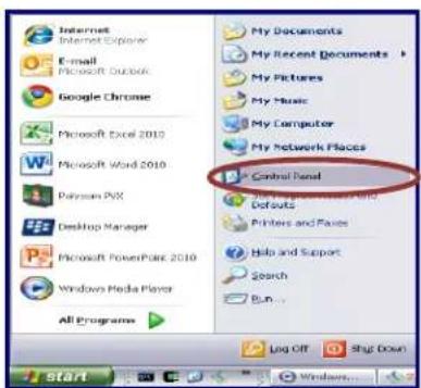
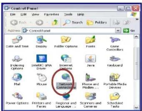
Figure 72: Network Connections
This displays the connections currently found on the PC. Select the icon for the Local Area Connection and double click to open the properties for this NIC.
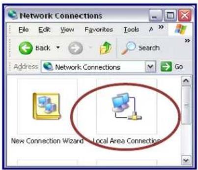
Figure 73: LAN Network Connection
Scroll through the protocols used by the local area connection to find the Internet Protocol (TCP/IP). Select this protocol by clicking on it and then click on the Properties button to open the window that will allow you to set the IP address and Subnet mask.
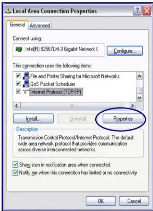
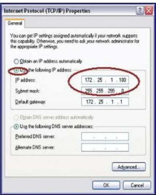
Figure 74: Network Settings Option 2 (See the Configuration Server Interface section)
Click the Radio button to "Use the following IP Address" and then enter both the IP address and Subnet mask as shown.
Action required!
Depending on the choice of IP address range above for the configuration of the EVSEs in the network, set the Ethernet IP address, Subnet Mask, and Default Gateway to the corresponding settings:
| IP Address | 172.25.1.100 |
| Subnet Mask | 255.255.255.0 |
| Default Gateway | 172.25.1.1 |
or
| IP Address | 172.26.1.100 |
| Subnet Mask | 255.255.255.0 |
| Default Gateway | 172.26.1.1 |
Click on OK and close both windows to save your settings.
Note: Make sure the Host PC is configured according to the same IP address settings as entered in the EVSE configuration server page.
Note: Reboot PC to finalize the configuration
4.4.3 Install EV100 RFID Host Application Software.
After the controller configuration of all EVSE and the host PC's TCP/IP setups have been completed, the Host Application EV100 for RFID authentication needs to be installed.
GE strongly recommends using a clean PC with a fresh Windows XP or Windows 7 installation only, to avoid any interference with other installed software.
In order to install EV100 application, make sure you have full Windows Administrator rights
The detailed installation steps are defined in the manual provided with the application on CD 1. "EV100 - GE EV Charging Station Manager Application". For trouble shooting, please also refer to that manual.
- Power up the network switch and keep it connected to the Host PC at all times during the SW installation and subsequent operation.
Note: Make sure the switch is always powered and connected to the Host PC. In case of a direct connection from the EVSE to a Host PC without interposed Ethernet switch, the EVSE needs to be powered each time the Host PC is powered up, or the listener service is manually restarted.
2. Install the SW
It is strongly recommended to install the SW in the default location.
- Insert CD 1 of the EV100 Application into the CD ROM and launch setup.exe
- Follow instructions and keep default Port settings of 3306
- Once finished with CD 1, insert CD 2 of the EV100 Application and launch setup.exe
- Follow instructions and keep default port settings at 9500 (unless another port has been set up in the individual EVSE stations on the configuration server page)
- Add optional field descriptions for user identification, such as phone number, e-mail address, etc. which shall be stored alongside the RFID identifier.
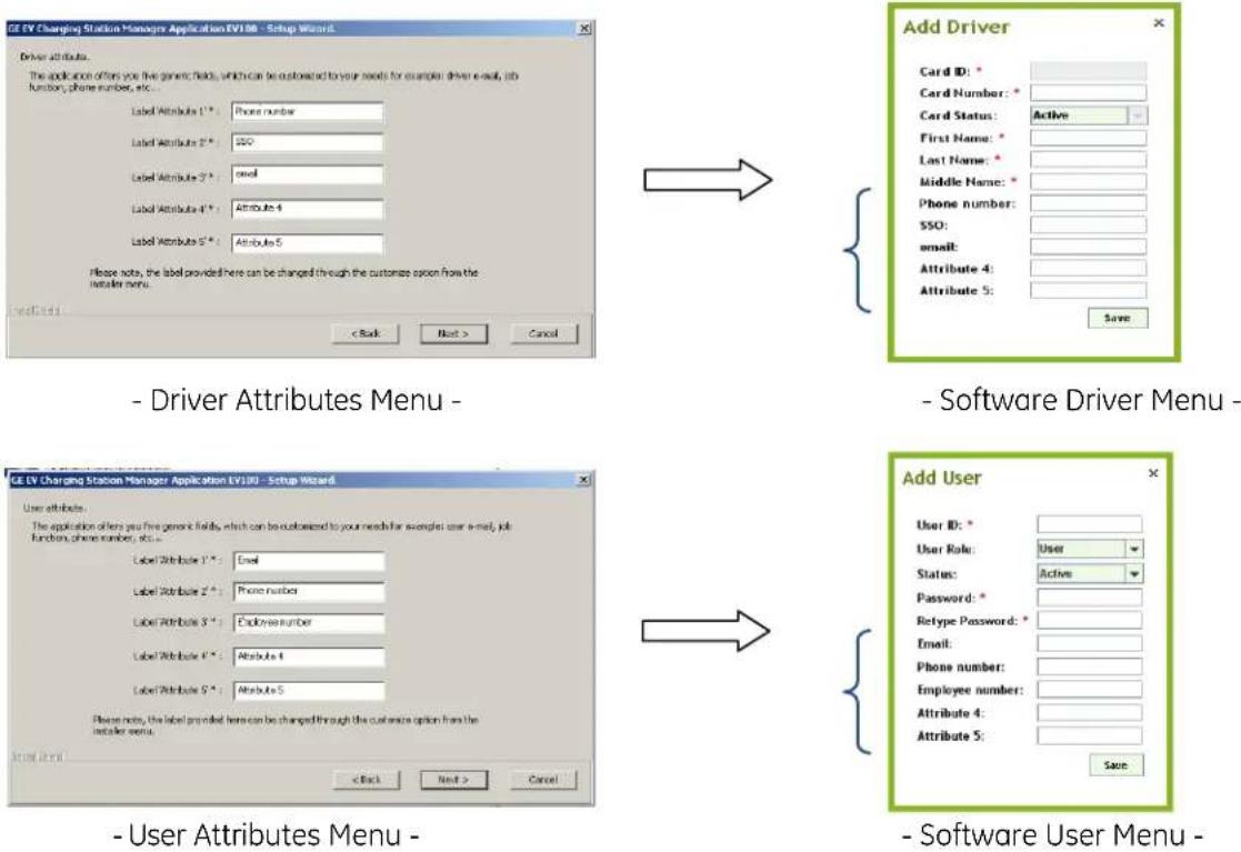
Figure 75
4.4.4 Setup Validation
After the successful installation of the EVSE network and EV100 Software, validate the installation by following these steps:
- Check that the EV100 Listener Service is running
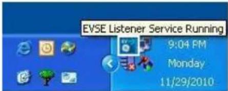
Note: A change of the Host PC IP address while the listener service is running requires a restart of the listener service or a reboot of the host PC. For detail instructions reach out to User Manual document included on CD 1.
2. Launch the EV100 Application
Start the EV100 Application and log in. Default login is "admin" and the password "admin".
You should now see the stations appear in the list with a green status after at most 5 min.
After at most 5min, all EVSE in the network should appear in the list. Check that all EVSE are present and listed with their correctly configured Station ID.
Should one of the EVSE not appear in the list, power that station down and up again.
Click on "Home" to refresh the screen at any time.
3. Enroll drivers
Note: "Users" are user accounts for the EV100 application with associated login and password. "Drivers" are EV drivers and are enrolled for usage of the EVSE infrastructure and identify themselves with RFID cards.
In order to enroll new drivers, follow these steps or detail instructions included in the Help>Add driver section
- Plug in the enrollment card reader (accessory from GE, cat # EVRP01) into the USB port
- Wait for the USB driver installation to successfully complete
- Click on "Add" to open the Add New Driver dialog box
- Click on "OK" then hold the RFID card of the new user in front of the enrolment reader for a few seconds. You should see a change in the LED on the reader itself and a hexadecimal number appear in the text field.
Note: If the keyboard is set to French or Belgium keep the CAPSLOCK ON during card ID registration. Should the output of the reader in the text field include characters other than 0-9 and A-F, set the keyboard settings of Windows to "US English".
- Fill in the remaining information.
- Add more drivers to the list. For more information, refer to the SW user manual or the help file.
- You can close the application EV100, but keep the host PC connected and up and running at all times for the RFID authentication to work.
4. Check driver registration
Any driver with a registered RFID card can now use the connected EVSE.
To activate charging, hold the RFID card in front of the reader for 2-3 seconds. Upon successful authentication of that card, the reader LED will turn green after another small delay of 2-3 seconds.
Note: For authentication to work, keep the host PC connected and up and running at all times.
4.5 Setup without RFID Authentication
Some EVSE models are not equipped with an RFID reader and are not meant to be set up in a network environment. Even models with RFID can be used in a non-authentication mode. In both cases, the EVSE controller settings do not need to be modified from the default values.
In order to disable the RFID authentication function from a previous networked setup, it is recommended to either reset the EVSE controller as explained in a later chapter, or to reset the values on the EVSE controller following the steps described in the Configuration Server Interface section, and set the parameters as shown.
After the desired settings were configured click on "Save".
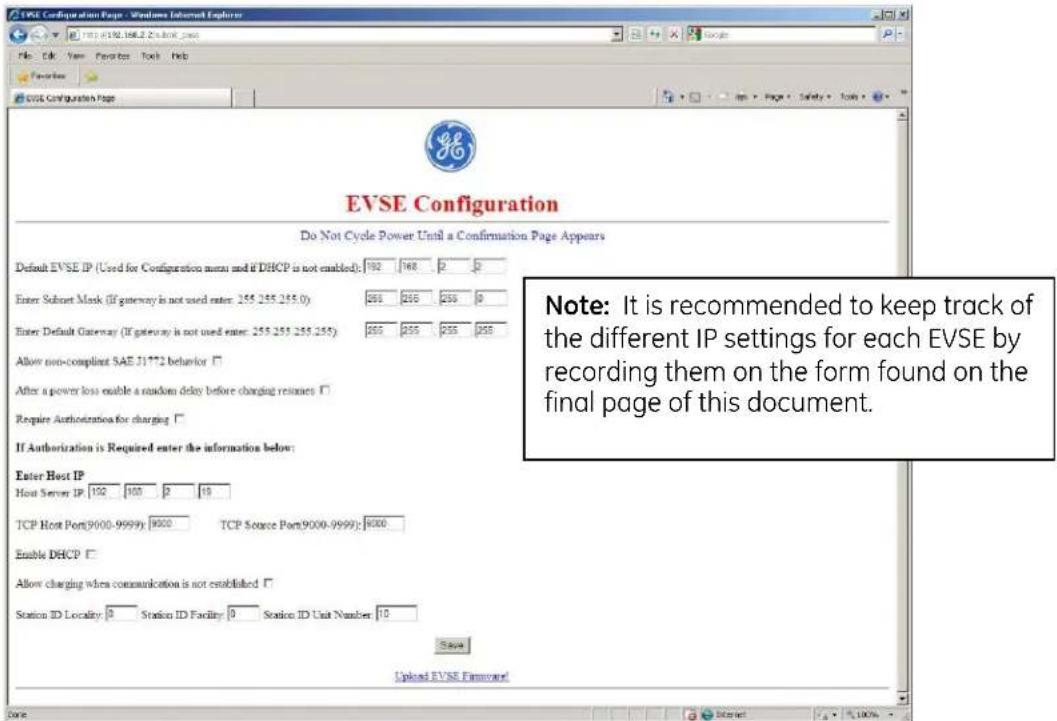
Figure 76: Factory Default values
4.6 Reset Controller to Factory Default
Should you have inadvertently changed to a non-default IP setting and cannot remember the IP settings, or simply reverse to default configuration for other reasons, you can reset the controller to the factory default values by following these steps.
Note: It is recommended to keep track of the different IP settings for each EVSE by recording them on the form found on the final page of this document.
Follow the instructions below to reset the controller settings:
- Switch off EVSE main breaker to remove power to the controller.
- Short connector J21 pins 1, 2 and 3 with a conductive connector.
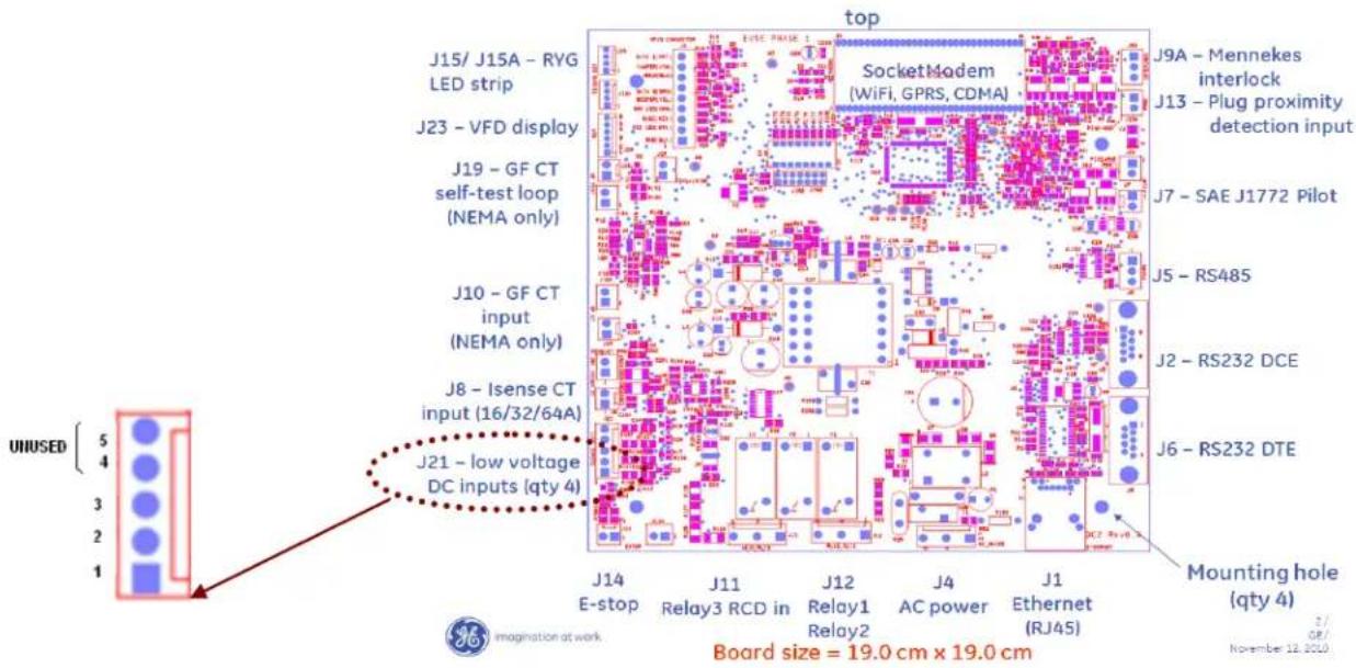
Figure 77
- Switch on EVSE main breaker to supply power to the controller.
- After a few seconds switch off EVSE main breaker to remove power to the controller.
- Remove short from connector J21.
-
Switch on EVSE main breaker to supply power to the controller.
-
Reconfigure as desired via EVSE controller configuration server interface. See description in an earlier chapter.
Note: In the case of a network installation with RFID authentication, after a reset of the controller, the Station ID must be modified to a new ID not previously used on this network to avoid transaction data to be lost.
4.7 Trouble Shooting Guide
For assistance with EVSE troubleshooting, please refer to the following website:
www.geindustrial.com/evsupport
EVSE Settings for ID \_\_\_\_
Locality: ____ Facility: ____ Unit Number: ____
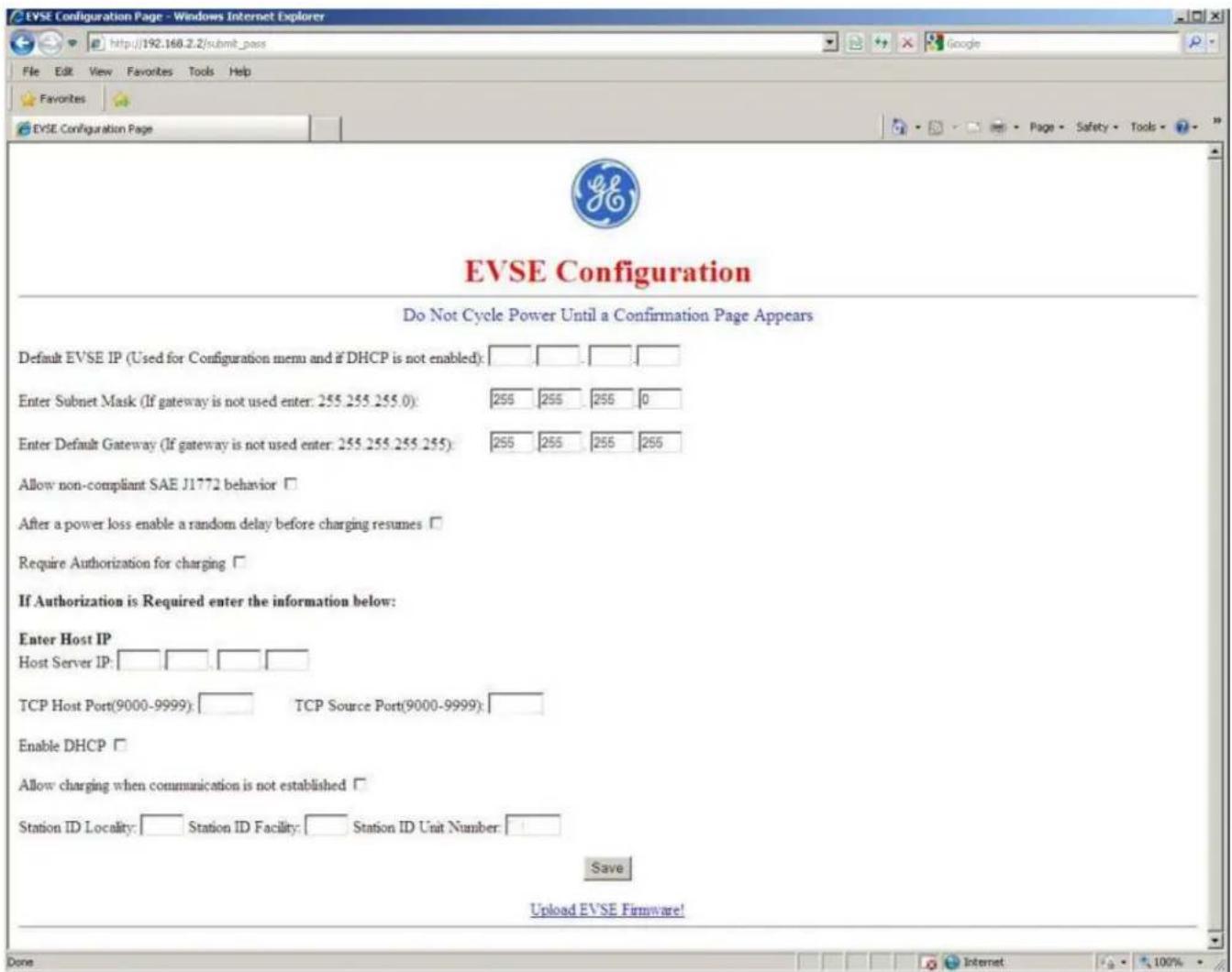
Print one page for each EVSE and keep this record in a safe location or inside the corresponding EVSE.
* SAVE THESE INSTRUCTIONS*
The instructions do not purport to cover all details or variations in equipment nor to provide for every possible contingency to be met in connection with installation, operation or maintenance. Should further information be desired or should particular problems arise which are not covered sufficiently for the purchaser's purposes, the matter should be referred to the GE company.
GE Industrial Solutions
41 Woodford Ave.
Plainville, CT 06062
www.geindustrial.com
DEH-44160
- CONTENTS
- Important Safety and Grounding Instructions
- Safety and Compliance
- WARNING:
- Grounding Instructions
- Installation Instruction
- Before Installing
- Safety Requirements
- Installation Overview and Specifications
- Pedestal
- Figure 4
- Double Pedestal (Back to Back)
- Figure 13
- DOUBLE PEDESTAL SKIRT INSTALLATION, AFTER CONCRETE POUR
- Wall-Mounted
- Pole-Mounted
- Accessory Kits
- Replacement Kits
- RFID
- VFD
- Holding Socket
- Service Door
- Wiring Diagram
- User Manual
- Receiving
- Status Indicator:
- Faults:
- Ground fault:
- Technical Data
- Additional Considerations
- EVSE Controller Settings
- Configuration Switch Settings
- Display fault messages
- 0x00000001
- 0x00000002
- 0x00000004
- 0x00000008
- 0x00000010
- 0x00000020
- 0x00000040
- 0x00000080
- 0x00000100
- 0x00000200
- 0x00000400
- 0x00001000
- 0x00004000
- 0x00008000
- 0x00010000
- 0x00040000
- 0x00080000
- 0x00200000
- Network Setup Instructions
- Definitions and Terms
- Firewall and Security Considerations
- Controller Configuration
- Introduction
- Prepare Service Laptop or PC
- \*Note:
- EVSE Configuration Server Interface
- To configure each individual EVSE
- Switch 8 - Open (Configuration server interface)
- The Controller will invoke the following page:
- Recommended Network Designs for RFID Authentication
- Option 1: Stand-alone Network Configuration
- Required Components:
- EVSE Controller Settings
- Action required!
- Host PC Settings
- Option 2: Charging Station Network isolated from Customer Network with Host System in a DMZ.
- • EVSE IP
- Host PC Settings:
- Install EV100 RFID Host Application Software.
- Install the SW
- Setup Validation
- Launch the EV100 Application
- Enroll drivers
- Check driver registration
- Setup without RFID Authentication
- Reset Controller to Factory Default
- Trouble Shooting Guide
- EVSE Settings for ID \_\_\_\_
Brand : GE
Model : DuraStation
Category : Uncategorized