
HEAE5430498-B - Thermostat Heatit - Free user manual and instructions
Find the device manual for free HEAE5430498-B Heatit in PDF.


| Product Type | Z-Wave Thermostat for electric heating |
| Brand | Heatit |
| Model | HEAE5430498-B |
| Color | Black RAL 9011 |
| Protocol | Z-Wave Plus, 868.4 MHz |
| Rated Voltage | 230V 50/60Hz |
| Max Load (Resistive) | 3600W |
| Max Load (Self-limiting cable) | 750W |
| Max Current | 16A |
| Power Consumption | 1.5W |
| Temperature Range (Floor/External Sensor) | 5°C to 40°C |
| Hysteresis (Adjustable) | 0.3°C to 3.0°C (default 0.5°C) |
| IP Class | IP21 |
| Dimensions (H x W x D) | 87 mm x 58.8 mm x 21.3 mm |
| Included Accessories | Floor sensor (3 m, NTC 10 kΩ) |
| Warranty | 2 years |
| Sensor Modes | Floor, Internal room, External room, Power regulator, Combinations |
| Display | Backlit with touch capacitive buttons |
| Child Lock | Yes (via button combination) |
| Safety | Install only by qualified electrician; disconnect power before installation |
| Cleaning | Wipe with a dry, soft cloth; do not use liquids or sprays |
Frequently Asked Questions - HEAE5430498-B Heatit
User questions about HEAE5430498-B Heatit
0 question about this device. Answer the ones you know or ask your own.
Ask a new question about this device
Download the instructions for your Thermostat in PDF format for free! Find your manual HEAE5430498-B - Heatit and take your electronic device back in hand. On this page are published all the documents necessary for the use of your device. HEAE5430498-B by Heatit.
USER MANUAL HEAE5430498-B Heatit
This thermostat is tested and certified by Pepper One GmbH according to the requirements put forward by the Z-Wave Alliance. This is a Z-wave Plus product with the 500 series chip. If the product does not work with your gateway, then the gateway manufacturer has not made an integration or implemented such a thermostat with their gateway. We do not give any guarantee towards integration.
PRINCIPLES FOR REGULATION
The Heatit Z-Wave thermostat is designed for controlling electrical heating cables and electrical radiators/convectors. The thermostat has 2 internal temperature sensors and has 3 algorithms for temperature compensation. After you have set the temperature, the thermostat will use a hysteresis to regulate the temperature. The hysteresis is adjustable.
TEMPERATURE SHOWN IN DISPLAY
The temperature shown in the display is the actual temperature for floor sensor and the external room sensor. You are able to calibrate the sensor values.
When using the internal room sensor, the temperature shown is the set point. When using the internal sensor, the thermostat can seem somewhat inaccurate. This is due to heat generation inside the thermostat, draft and other external influences.
If the thermostat is to be used with waterbased heating systems, you have to use an external sensor.
SETUP
This manual describes the most essential functions and technical specifications of the thermostat. These instructions help the user to control the thermostat, and the electrician to install and setup the thermostat.
INSTALLATION
Installation must be done by a qualified electrical installer in accordance with the National Building codes. Before installation, disconnect any power to the thermostat's mains. During installation of the thermostat, power to the thermostat must be disconnected AT ALL TIMES!
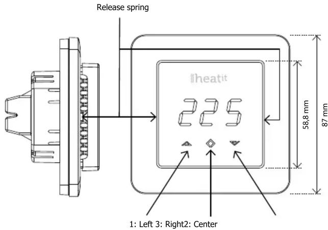
Use e.g. a small slotted screwdriver. Start by carefully removing the front cover by pushing the release springs. The front cover and the frame can now be removed.
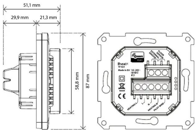
Now connect the wires to the thermostat's terminals:
HEATING (N) Heating cable connection (Neutral)
N Power connection (Neutral) 230V
L Power connection (Live) 230V
HEATING (L) Heating cable connection (Live)
PILOT Pilot signal (ECO temp) 230V
FLOOR SENSOR NTC type (10, 12, 15, 22, 33 or 47kΩ).
Default 10kΩ.
EXTERNAL SENSOR NTC type (10, 12, 15, 22, 33 or 47kΩ).
Default 10kΩ.
Next, position the thermostat and fasten it onto the wall's mounting box using 2-4 screws. Position the frame, then position and carefully press the front cover until it snaps in place. Check that the front cover has snapped in place properly on both left and right side. The front cover should now be firmly fixed on all sides.
STARTUP
AFTER CONNECTING THE POWER TO THE THERMOSTAT FOR THE FIRST TIME, ALL PARAMETERS WILL HAVE DEFAULT SETTINGS.
CONTROL
The thermostat is controlled by three touch sensitive capacitive buttons.
You only need to touch lightly to activate the buttons.
1: Left (Up)
2: Center (Confirm)
3: Right (Down)
INCLUSION/EXCLUSION
To include the thermostat to your home automation gateway, press Center (confirm) for 10 seconds.
The display will show OFF. Press Right (down) 4 times till you see Con in the display. Now start add device in your home automation software. Start inclusion mode by pressing Center (confirm) for approximately 2 seconds. The inclusion/exclusion icon will appear in the display. Confirmation will show Inc/EcL in the display. If inclusion fails, Err (error) will appear.
Leave programming mode by choosing ESC in menu.
Your thermostat is ready for use with default settings.
PROGRAMMING YOUR THERMOSTAT
To activate the programming mode, press Center (confirm) for 10 seconds. Now the display will show OFF.
Now you are in programming mode. To scroll up and down in the menu use button 1 and 3 (left and right) to navigate.
To enter submenu press Center (confirm). Always confirm your setting by pressing Center (confirm) for 2 seconds.
Menu:
OFF Turns the thermostat off.
Sensors:
F Floor sensor
A Internal room sensor
AF Internal room + Floor sensor
A2 External room sensor
P Power regulator
FP Floor sensor + Power regulator
A2F External room sensor + Floor sensor
Depending on your choice of sensors, the menu will change.
SEn Select the right Ohm value for your external/floor sensor. NTC type (10, 12, 15, 22, 33 or 47kΩ). Default 10kΩ.
CAE Calibration for external sensor.
CAF Calibration for floor sensor.
CAR Calibration for room sensor.
br1 Brightness of display can be adjusted in this menu.
Con Activation of inclusion/exclusion mode.
diF Hysteresis
ALo Setting lowest allowed temperature (limitation). (Airsensor)
AHI Setting highest allowed temperature (limitation). (Airsensor)
FLO Setting lowest allowed temperature (limitation). (Floor sensor)
FHI Setting highest allowed temperature (limitation). (Floor sensor)
HEA Switch between heating and cooling function.
ESC Escape – exit programming menu.
PRODUCT INFO Heatit Z-Wave
FEATURES
| Floor sensor | LED-diode |
| External room sensor | Can be used in connection with different NTC-sensors |
| Internal room sensor | |
| Temperature limiter | Lock mode/child lock |
| Power regulator | Backlight |
| Z-Wave Plus, 500 series | Calibration |
| Weekly program via gateway | 8 associations |
| Setback mode via gateway or pilot wire |
TECHNICAL DATA
| Protocol | Z-Wave Plus, 868,4 MHz |
| Rated voltage | 230V 50/60Hz |
| Max load | 3600W (resistive load) |
| 750W self-limiting heating cable | |
| Max current | 16A |
| Power consumption | 1,5W |
| Power regulator | Time cycle 0-30 min |
| Min/max installation temp. | -20°C to 40°C |
| Min/max operating temp. | 5°C to 40°C |
| Temperature intervals | Floor sensor 5°C to 40°C |
| External room sensor 5°C to 40°C | |
| Hysteresis | 0,3°C to 3,0°C (default 0,5°C) |
| Sensor values | 0°C 29,1 kOhm |
| 10°C 18,6 kOhm | |
| 15°C 15,1 kOhm | |
| 20°C 12,2 kOhm | |
| 25°C 10,0 kOhm | |
| Switch | Single-pole switch |
| IP class | IP21 |
TERMINAL
Use 1,5 mm ^2 or 2,5 mm ^2 according to load.
INCLUDED IN PACKAGE
Floor sensor 3 meters, Art. no. 5430109
WARRANTY
2 years
The thermostat is designed for electrical heating.
| ART. NO. | PRODUCT | COLOR |
| 5430499 | Heatit Z-Wave thermostat 3600W 16A | White RAL 9003 |
| 5430498 | Heatit Z-Wave thermostat 3600W 16A | Black RAL 9011 |
| 5430311 | Frame for Heatit | White RAL 9003 |
| 5430312 | Frame for Heatit | Black RAL 9011 |
| 5430497 | Cable for software update on thermostat |
| 5430108 | Floor sensor ∅3mm 6m NTC 10 kOhm |
| 5430109 | Floor sensor ∅4mm 3m NTC 10 kOhm |
| 5430128 | External room sensor, glass front NTC 10 kOhm |
| 5430471 | External enclosed sensor IP 20/54 |
CHOICE OF SENSOR
The thermostat has a range of choices when it comes to sensors. To get to the menu you have to press Center (confirm) for 10 seconds, then press Right (down) once and an A shows in the display. Then press Center (confirm) again and you can choose one of these modes, while moving up and down with buttons Left or Right.
F Floor sensor
A Internal room sensor
AF Internal room sensor + Floor sensor
A2 External room sensor
P Power regulator
FP Floor sensor + Power regulator
A2F External room sensor + Floor sensor
When you have decided on the sensor mode you want to use, press the Center (confirm) button. If you choose F or AF without having a floor sensor connected, Er4 will be shown in the display. If you choose A2 or A2F and there is no external sensor installed, Er5 will be displayed on the screen.
NOTE: Wooden floors require that a floor sensor is connected in order to limit the floor temperature to a maximum of 27^ C (in accordance with specifications from most wooden floor manufacturers).
SELECT THE RIGHT OHM VALUE FOR YOUR EXTERNAL/FLOOR SENSOR
The following values are available: NTC type (10, 12, 15, 22, 33 or 47kΩ). Default 10kΩ. The function is only active when an external sensor is connected. Confirm with Center (confirm) button.
CALIBRATION
In this mode you are able to adjust the displayed temperature. If the thermostat of some reason (or sensor) is not calibrated properly you are able to make minor changes to the temperature. You are able to raise/lower the set point by up to 4°C. Confirm with Center (confirm) button. This function is only available for the floor sensor and external room sensor. When calibrating the room sensor, only the setpoint is changed. The display will not change.
BRIGHTNESS
Use Left and Right (up and down) button to adjust the brightness between 0-9. Confirm with Center (confirm) button.
INCLUSION/EXCLUSION
To include the thermostat to your home automation gateway, press Center (confirm) button for 10 seconds. The display will show OFF. Press Right (down) 4 times till you see Con in the display. Now start add device in your home automation software. Start inclusion mode by pressing Center (confirm) button for approximately 2 seconds. The inclusion/exclusion icon will appear in the display. Confirmation will show Inc/EcL in the display. If inclusion fails, Err (error) will appear.
HYSTERESIS (DIF)
In this mode you are able to make changes to the hysteresis in the thermostat. This means that you can change the hysteresis from 0.2^ C up to max 3.0^ C. Confirm with Center (confirm) button. Default setting is 0.5^ C. When using a waterbased heating, the recommended hysteresis is a minimum of 1.0^ C.
MIN/MAX TEMPERATURE SETTINGS
FLO Min Floor temperature
FHI Max Floor temperature
ALO Min Air/room temperature
AHI Max Air/room temperature
PLO Min temperature in Power Reg Mode Confirm with Center (confirm)
HEA Choose whether the thermostat is to be used for heating or cooling.
ESC Leaving programming mode. Confirm with Center (confirm) button.
STANDBY AND MAIN SCREEN
When the thermostat remains untouched for a while, it will automatically go to standby screen. Standby screen shows the temperature in the room or floor if the thermostat is connected to external sensors. By pressing Left or Right (up or down) button the setpoint will be shown in the display. If the internal room sensor is used, the thermostat display shows the setpoint.
DISPLAY ON/OFF - DON/DOF
Activate by pressing Left and Center (up and confirm) button for 10 seconds. The display light is temporarily activated if one of the buttons is pushed.
In case doF is activated, the screen will be blank (can be used if installed where people are sensitive to the light of the display). A very nice feature when used in a bedroom. When touching the display, the screen lights up.
CHILDLOCK - LOC
By pressing Left and Right (up and down) buttons for 10 seconds, child lock will be activated and no changes can be made. Trying to make changes causes the LOC text to appear in the display. Child lock is deactivated by pressing Left and Right (up and down) buttons for 10 seconds. OPn will appear in the display.
FACTORY RESET - RES
By pressing buttons Right and Center (down and confirm) for 20 seconds, the thermostat will perform a complete factory reset. NB! Please use this procedure only when the primary controller/gateway is missing or otherwise inoperable.
CO/ECO MODE
The thermostat has 2 main programs, CO – comfort mode and ECO - economy mode. When Center (confirm) button is pushed for 2 seconds you switch between the 2 modes. You would normally have 2 different set-points for the different modes.
CO – mode: Is used for normal use. Example: 21°C. ECO – mode: Is a setback mode that you can use if the thermostat is installed in a room or a house that is rarely used.
The ECO-mode can also be activated by the pilot wire if this is connected. Example: 18°C. Some gateways also support switching between CO/ECO mode. In most circumstances, the CO/ECO function can be regarded as a home/away function.
COMMAND CLASSES
In order to run some schedule or week program, the primary controller/gateway should be responsible for controlling the thermostat using those selected command classes.
Classes:
GENERIC_TYPE_THERMOSTAT
SPECIFIC_TYPE_SETPOINT_THERMOSTAT
COMMAND_CLASS_BASIC
COMMAND_CLASS_THERMOSTAT_SETPOINT_V3
COMMAND_CLASS_THERMOSTAT_SETBACK
COMMAND_CLASS_SENSOR_MULTILEVEL
COMMAND_CLASS_VERSION
COMMAND_CLASS_MANUFACTURER_SPECIFIC
COMMAND_CLASS_ASSOCIATION
+ All other mandatory classes for selected device type
COMMAND_CLASS_CONFIGURATION_V2
Supports parameter numbers from 1 to 12 (if cooling enabled, from 1 to 13). Accepts byte sizes 1.2 and 4 bytes, but it is recommended to use 2-byte parameters in order to get access to the whole temperature range.
ERROR CODES
| Er1: | Internal error |
| Er2: | Z-Wave error |
| Er3: | Internal error |
| Er4: | Floor sensor error |
| Er5: | External sensor error |
If you have chosen F or AF sensor mode without having a floor sensor connected, Er4 will be shown in the display. If you have chosen A2 or A2F, and there is no external sensors installed, Er5 will be shown in the display. If the Er1, Er2 or Er3 error codes are shown, contact your local dealer or Thermo-Floor AS.
| PARAMETER DESCRIPTION RANGE DEFAULT WHAT IF | VALUE OUT OF RANGE: | |||
| 1 Operation mode | 0x00 OFF | 0x01 HEAT(0x02 COOL)0x0B ENERGY SAVE HEAT | 0x01 HEAT Ignored | |
| 2 Sensor mode 0: | F-mode | 1: A-mode2: AF-mode3: A2-mode4: P-mode5: FP-mode | 1: A Ignored | |
| 3 Floor sensor type | 0: 10k NTC | 1: 12k NTC2: 15k NTC3: 22k NTC4: 33k NTC5: 47k NTC | 0: 10k NTC Ignored | |
| 4 DIFF I. Temperature control Hysteresis | 3-30 (0.3°C 3.0°C) 5: 0.5°C Ignored | |||
| 5 | FLo, Floor min limit | 50-400 (5.0°C 40.0°C) | 50: 5.0°C | Ignored |
| 6 | FHi, Floor max limit | 50-400 (5.0°C 40.0°C) | 400: 40.0°C | Ignored |
| 7 | ALo, Air min limit | 50-400 (5.0°C 40.0°C) | 50: 5.0°C | Ignored |
| 8 | AHi, Air max limit | 50-400 (5.0°C 40.0°C) | 400: 40.0°C | Ignored |
| 9 PLo, FP-mode P setting | 0-9 | 0 | Ignored | |
| 10 | CO mode setpoint | 50-400 (5.0°C 40.0°C) | 210: 21.0°C | Ignored |
| 11 | ECO mode setpoint | 50-400 (5.0°C 40.0°C) | 180: 18.0°C | Ignored |
| 12 | P setting | 0-10 | 2 | Ignored |
| 13 (only if cooling enabled) | COOL setpoint | 50-400 (5.0°C 40.0°C) | 210: 21.0°C | Ignored |
Thermo-Floor AS can
not be held liable for
typographical errors, other
errors or omittances in
our information.
Product specifications
may change without
further notice.
All electrical installations
must be carried out by a
licensed electrician.
The product must be installed
in accordance with national
building codes and our
installation guides.
- PRINCIPLES FOR REGULATION
- TEMPERATURE SHOWN IN DISPLAY
- SETUP
- INSTALLATION
- STARTUP
- CONTROL
- INCLUSION/EXCLUSION
- PROGRAMMING YOUR THERMOSTAT
- PRODUCT INFO Heatit Z-Wave
- TERMINAL
- INCLUDED IN PACKAGE
- WARRANTY
- CHOICE OF SENSOR
- SELECT THE RIGHT OHM VALUE FOR YOUR EXTERNAL/FLOOR SENSOR
- CALIBRATION
- BRIGHTNESS
- HYSTERESIS (DIF)
- MIN/MAX TEMPERATURE SETTINGS
- STANDBY AND MAIN SCREEN
- DISPLAY ON/OFF - DON/DOF
- CHILDLOCK - LOC
- FACTORY RESET - RES
- CO/ECO MODE
- COMMAND CLASSES
Brand : Heatit
Model : HEAE5430498-B
Category : Thermostat