
DM-TX-200-2G - Audio/video extender Crestron - Free user manual and instructions
Find the device manual for free DM-TX-200-2G Crestron in PDF.


| Product Type | Audio/video extender and 2x1 switcher |
| Brand | Crestron |
| Model | DM-TX-200-2G |
| Dimensions (H x W x D) | 4.12 in x 3.50 in x 2.53 in (105 mm x 89 mm x 64 mm) |
| Weight | 11 oz (285 g) |
| Power Consumption | 10 Watts (0.42 Amps @ 24 VDC) |
| Power Source | DMNet (powered via connected DM switcher or DM-RMC-100) |
| Video Inputs | 1 HDMI (HDCP, DVI, DisplayPort Multimode compatible), 1 RGB (DB15HD, supports component) |
| Audio Input | 1x 3.5 mm TRS stereo analog (unbalanced) |
| Video Output | DM CAT (DigitalMedia over twisted pair), up to 450 ft (137 m) with repeaters |
| Switching Type | Auto-detect, priority-based (HDMI, RGB, audio) |
| Control Features | EDID management, CEC embedded device control, USB HID keyboard/mouse extension |
| Mounting | 2-gang wall mount (standard electrical box, 2.5 in deep minimum) |
| Color Options | Black or white |
| Operating Temperature | 32°F to 104°F (0°C to 40°C) |
| Operating Humidity | 10% to 90% RH (non-condensing) |
| Regulatory Compliance | FCC Class B, CE, IC |
| Diagnostic Indicators | PWR, RESET, HDMI, PC, DM LINK LEDs, SETUP button |
| Included Accessories | Mounting screws, cable clamps |
| Maintenance | Wipe with a dry cloth; no user-serviceable parts inside |
Frequently Asked Questions - DM-TX-200-2G Crestron
User questions about DM-TX-200-2G Crestron
0 question about this device. Answer the ones you know or ask your own.
Ask a new question about this device
Download the instructions for your Audio/video extender in PDF format for free! Find your manual DM-TX-200-2G - Crestron and take your electronic device back in hand. On this page are published all the documents necessary for the use of your device. DM-TX-200-2G by Crestron.
USER MANUAL DM-TX-200-2G Crestron
Crestron DM-TX-200-2G/400-3G
Wall Plate DigitalMedia™ CAT
Transmitters
Operations & Installation Guide
This document was prepared and written by the Technical Documentation department at:

CRESTRON®
Crestron Electronics, Inc.
15 Volvo Drive
Rockleigh, NJ 07647
1-888-CRESTRON
Regulatory Compliance
As of the date of manufacture, the DM-TX-200-2G and DM-TX-400-3G have been tested and found to comply with specifications for CE marking and standards per EMC and Radiocommunications Compliance Labelling.

Federal Communications Commission (FCC) Compliance Statement
This device complies with part 15 of the FCC Rules. Operation is subject to the following conditions: (1) This device may not cause harmful interference and (2) this device must accept any interference received, including interference that may cause undesired operation.
CAUTION: Changes or modifications not expressly approved by the manufacturer responsible for compliance could void the user's authority to operate the equipment.
NOTE: This equipment has been tested and found to comply with the limits for a Class B digital device, pursuant to part 15 of the FCC Rules. These limits are designed to provide reasonable protection against harmful interference in a residential installation. This equipment generates, uses and can radiate radio frequency energy and, if not installed and used in accordance with the instructions, may cause harmful interference to radio communications. However, there is no guarantee that interference will not occur in a particular installation. If this equipment does cause harmful interference to radio or television reception, which can be determined by turning the equipment off and on, the user is encouraged to try to correct the interference by one or more of the following measures:
• Reorient or relocate the receiving antenna
- Increase the separation between the equipment and receiver
- Connect the equipment into an outlet on a circuit different from that to which the receiver is connected
- Consult the dealer or an experienced radio/TV technician for help
Industry Canada (IC) Compliance Statement
This Class B digital apparatus complies with Canadian ICES-003.
Features and Functions....1
Applications....4
Specifications 5
Physical Description....9
Setup....16
Network Wiring....16
Identity Code....16
Auto-Detect Switching....17
Supplied Hardware....17
Installation....18
Hardware Hookup 23
Programming Software....26
Earliest Version Software Requirements for the PC 26
Programming with Crestron SystemBuilder....26
Programming with SIMPL Windows....26
Uploading and Upgrading....29
Establishing Communication....29
Firmware 31
IP Configuration....32
DMTool....32
Problem Solving 33
Troubleshooting....33
Check Network Wiring....34
Reference Documents....35
Further Inquiries....35
Future Updates 35
Return and Warranty Policies....36
Merchandise Returns / Repair Service 36
CRESTRON Limited Warranty....36
GNU General Public License 37
Wall Plate DigitalMedia™ CAT
Transmitter 200/400:
DM-TX-200-2G/400-3G
Introduction
The DM-TX-200-2G and the DM-TX-400-3G are DM ^® CAT transmitters and switchers that install in a double-gang or a triple-gang electrical box (respectively) to provide a convenient interface for computers and high-definition AV sources as part of a complete DigitalMedia ^™ system.
With both HDMI ^® and RGB inputs, the DM-TX-200-2G and DM-TX-400-3G are ideal for wall, lectern, and floor box applications in a boardroom, classroom, or residence to provide an input for a laptop computer or similar source. The DM-TX-400-3G includes additional input connections for SPDIF and analog AV sources. Both transmitters connect to any DM-MD series DigitalMedia switcher or DM-RMC-100 Room Controller (all sold separately) via a single DM cable.
Features and Functions
• DigitalMedia transmitter and multimedia interface
• Built-in 2x1 (DM-TX-200-2G) or 4x1 (DM-TX-400-3G) AV switcher
• DM CAT output supports up to 450 foot (137 meter) cable length ^1
- 2-gang (DM-TX-200-2G) or 3-gang (DM-TX-400-3G) wall mount design
• Available colors include black or white
- Provides HDMI, RGB, component, and composite video inputs ^2
• Supports DVI and DisplayPort Multimode sources ^3
- Includes S/PDIF, RCA, and mini-TRS audio inputs ^4
(Continued on following page)
- For DigitalMedia CAT wiring, use DM-CBL DigitalMedia Cable. Up to two DM Repeaters (Model DM-DR, sold separately) may be required. Refer to the latest version of the Crestron DigitalMedia Design Guide (Doc. 4789) for complete wiring guidelines. It is available from the Crestron Web site (www.crestron.com/dmresources).
- Composite video inputs only available on DM-TX-400-3G.
- HDMI requires an appropriate adapter or interface cable to accommodate a DVI or DisplayPort Multimode signal. CBL-HD-DVI and CBL-DP-HD interface cables available separately.
- S/PDIF and RCA audio inputs only available on DM-TX-400-3G.
Features and Functions
(Continued)
- Provides onboard auto-switching capability
- Includes USB HID (human interface device) keyboard/mouse port
- Affords single-wire connection to a DM-RMC-100 or DM-MD switcher (both sold separately)
• Detects and reports detailed video and audio input information
• Performs automatic AV signal format management via EDID - Enables device control via CEC
- Easy setup and diagnostics tools via software
• Extends the life of analog-based AV systems
DigitalMedia
As the leader in HDMI and control system technologies, Crestron ^® has developed DigitalMedia, the first complete HD AV distribution system that takes HDMI to a higher level, and allows virtually any mix of AV sources to be distributed throughout the home, office, school, or virtually any other facility.
DigitalMedia distributes uncompressed digital video and audio signals up to 450 feet (137 meters) using DM cable ^1 . DigitalMedia thoughtfully manages all of the different signals and devices, matching each source's output to the capabilities of the selected display(s) without using scaling or compression. Every signal is preserved in its native video resolution and audio format, ensuring a pure, lossless signal path throughout.
Multimedia Computer/AV Interface
The DM-TX-200-2G provides simple switching between two inputs. The DM-TX-400-3G provides versatile switching between four different video and audio inputs. The HDMI input supports HDCP and handles WUXGA computer resolutions and 1080p60 HDTV with multi-channel lossless audio. The HDMI input can also handle DVI and DisplayPort Multimode signals using an appropriate adapter or dongle ^2 . The RGB input handles all analog RGB signals up to WUXGA 1920x1200 pixels, as well as component video up to 1080p60 ^3 . A mini-TRS stereo audio input is also provided to accept analog audio signals from an unbalanced line-level or headphone output. On the DM-TX-400-3G, both digital and analog audio signals are supported via HDMI, S/PDIF, and RCA inputs.
Used with a single DM-RMC-100 Room Controller and optional Crestron Control System (both sold separately), the DM-TX-300-2G and DM-TX-400-3G afford very simple solutions for extending a multimedia computer or AV signal to a single display up to 450 feet (137 m) away ^1 . As part of a larger system using a DM-MD series switcher, multiple DM-TX-200-2G and DM-TX-400-3Gs may be installed to enable the distribution of several sources at different locations to feed multiple displays throughout any room or larger facility.
- For DigitalMedia CAT wiring, use DM-CBL DigitalMedia Cable. Up to two DM Repeaters (Model DM-DR, sold separately) may be required. Refer to the latest version of the Crestron DigitalMedia Design Guide (Doc. 4789) for complete wiring guidelines.
- HDMI requires an appropriate adapter or interface cable to accommodate a DVI or DisplayPort Multimode signal. CBL-HD-DVI and CBL-DP-HD interface cables available separately.
- The RGB input can accept component, composite, and S-video signals via direct interface to Crestron MPS Series products, or through an appropriate adapter (not included). Input sync detection is not provided for composite or S-video signal types through the RGB connection.
Keyboard/Mouse Extender
When connected to a DM-MD series switcher, the DM-TX-200-2G and DM-TX-400-3G function as keyboard/mouse extenders, allowing a USB HID (Human Interface Device) compliant keyboard and/or mouse at the podium or conference table to control a computer or other host device located at the central equipment rack.
EDID Format Management
The DM-TX-200-2G and DM-TX-400-3G allow for management of the EDID (Extended Display Identification Data) information that passes between the display devices and input sources in the system. Using Crestron Toolbox™ software, the format and resolution capabilities of each device can be assessed and managed through the DM-TX-200-2G or DM-TX-400-3G, ensuring reliable operation by instructing sources to output only the resolutions and formats that can be handled by the displays and system wiring.
CEC Embedded Device Control
The primary objective of every Crestron system is to enable precisely the control desired for a seamless user experience. DigitalMedia provides an alternative to conventional IR and RS-232 device control by harnessing the CEC (Consumer Electronics Control) signal embedded in HDMI. Through its connection to the control system, the DM-TX-200-2G or DM-TX-400-3G provides a gateway for controlling the connected source device right through the HDMI connection, potentially eliminating the need for any dedicated control wires or IR probes. Through proper CEC signal management, DigitalMedia allows you to take control of each device in the system as you like.
Simple Wall Mount Design
The DM-TX-200-2G and DM-TX-400-3G are designed to be wall mounted using a standard electrical box or plaster ring. The DM cable is terminated at the rear of the transmitter using screw terminals. An array of indicators on the front of the DM-TX-200-2G and DM-TX-400-3G provide for easy setup and troubleshooting, verifying the status of connections and signal activity at a glance. Advanced configuration is enabled through Crestron Toolbox software.
A Digital Upgrade for Legacy Systems
The DM-TX-200-2G and DM-TX-400-3G also afford perfect signal converters for integrating DigitalMedia with analog-based systems like Crestron MPS, QuickMedia ^® , and the CEN-RGBHV Series (all sold separately). A simple HD15 VGA cable connected between the output of an MPS system and the input of the DM-TX-200-2G or DM-TX-400-3G allows every RGB, component, S-video, and composite video input on the MPS to be converted to DigitalMedia ^* . Analog audio is converted similarly through a simple unbalanced stereo audio cable. The HDMI input may also be used to expand the input capabilities of the MPS system to handle digital AV sources.
Applications
The following diagram shows a DM-TX-200-2G and a DM-TX-400-3G in a typical application.
DM-TX-200-2G and DM-TX-400-3G in a Typical Application
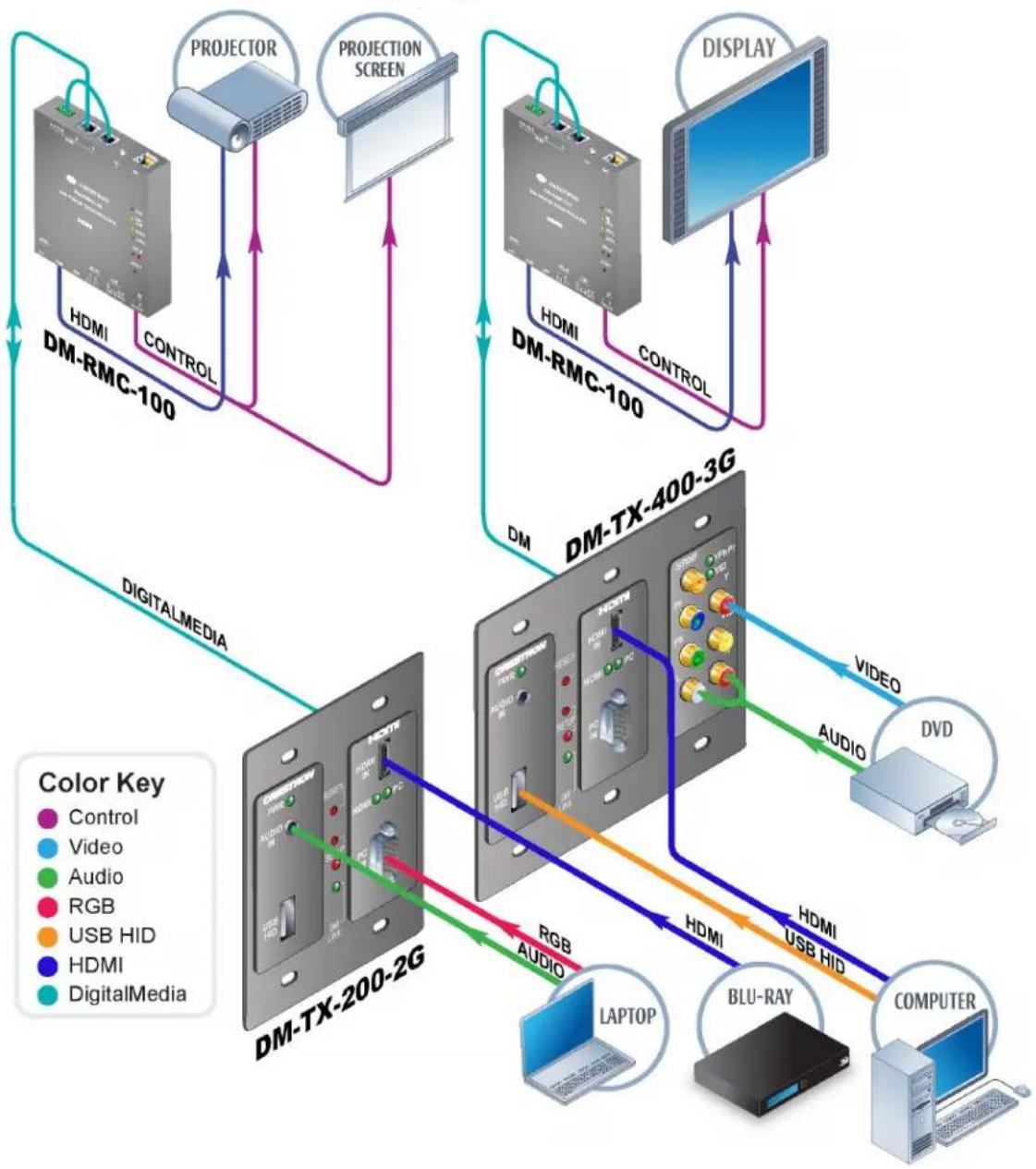
flowchart
graph TD
    subgraph_DM_RMC-100["DM-RMC-100"]
        A["Control"] -->|HDMI| B["Projection Screen"]
        C["Control"] -->|HDMI| D["Display"]
        E["Control"] -->|HDMI| F["Display"]
    end

    subgraph_DM-TX-400-3G["DM-TX-400-3G"]
        G["Video"] --> H["DVD"]
        I["Audio"] --> J["HDMS"]
        K["DigitalMedia"] --> L["Computer"]
    end

    M["DM-TX-200-2G"] --> N["Blu-Ray"]
    O["Laptop"] --> P["Computer"]
    Q["RGB Audio"] --> R["HDMI"]
    S["RGB Audio"] --> T["HDMI"]
    U["RGB Audio"] --> V["HDMI"]
    W["RGB Audio"] --> X["HDMI"]
    Y["RGB Audio"] --> Z["HDMI"]
    style A fill:#f9f,stroke:#333
    style C fill:#f9f,stroke:#333
    style E fill:#f9f,stroke:#333
    style F fill:#f9f,stroke:#333
    style G fill:#ccf,stroke:#333
    style I fill:#ccf,stroke:#333
    style Q fill:#ccf,stroke:#333
    style M fill:#cfc,stroke:#333
    style N fill:#cfc,stroke:#333
    style O fill:#cfc,stroke:#333
    style P fill:#cfc,stroke:#333
    style Q fill:#cfc,stroke:#333
    style R fill:#fcc,stroke:#333
    style S fill:#fcc,stroke:#333
    style T fill:#fcc,stroke:#333
    style V fill:#fcc,stroke:#333
    style W fill:#fcc,stroke:#333
    style X fill:#fcc,stroke:#333
Specifications
Specifications for the DM-TX-200-2G and DM-TX-400-3G are listed in the following table.
DM-TX-200-2G and DM-TX-400-3G Specifications
| SPECIFICATION | DETAILS |
| Video | |
| Switcher | |
| DM-TX-200-2G | 2x1 combination digital/analog switch, Crestron QuickSwitch HD ^ |
| DM-TX-400-3G | 4x1 combination digital/analog switch, Crestron QuickSwitch HD |
| Input Signal Types | HDMI, DVI ^1 , DisplayPort Multimode ^1 , RGB, component (YP _b Pr) ^2 , S-video (Y/C) ^2 , composite ^2 |
| Output Signal Type | DM CAT (DigitalMedia over twisted-pair copper wire) |
| Formats | HDMI, DVI, HDCP content protection support, RGBHV up to UXGA/WUXGA, HDTV up to 1080p60, NTSC or PAL |
| Input Resolutions | |
| HDMI & DVI, Progressive | 640 x 480 @ 60 Hz720 x480 @ 60 Hz (480p)720 x 576 @ 50 Hz (576p)800 x 600 @ 60 Hz848 x 480 @ 60 Hz852 x 480 @ 60 Hz854 x 480 @ 60 Hz1024 x 768 @ 60 Hz1024 x 852 @ 60 Hz1024 x 1024 @ 60 Hz1280 x 720 @ 50 Hz (720p50)1280 x 720 @ 60 Hz (720p60)1280 x 768 @ 60 Hz1280 x 800 @ 60 Hz1280 x 960 @ 60 Hz1280 x 1024 @ 60 Hz1360 x 768 @ 60 Hz1365 x 1024 @ 60 Hz1366 x 768 @ 60 Hz1400 x 1050 @ 60 Hz1440 x 900 @ 60 Hz1600 x 900 @ 60 Hz1600 x 1200 @ 60 Hz1680 x 1050 @ 60 Hz1920 x 1080 @ 24 Hz (1080p24)1920 x 1080 @ 25 Hz (1080p25)1920 x 1080 @ 50 Hz (1080p50)1920 x 1080 @ 60 Hz (1080p60)1920 x 1200 @ 60 Hz2048 x 1080 @ 24 Hz2048 x 1152 @ 60 Hzplus any other resolution allowed by HDMI up to 165 MHz pixel clock |
| Input Resolutions (Continued) | |
| HDMI & DVI, Interlaced | 720 x 480 @ 30 Hz (480i) |
| 720 x 576 @ 25 Hz (576i) | |
| 1920 x 1080 @ 25 Hz (1080i25) | |
| 1920 x 1080 @ 30 Hz (1080i30) | |
| plus any other resolution allowed by HDMI up to 165 MHz pixel clock | |
| RGB | 640 x 480 @ 60 Hz |
| 720 x 480 @ 60 Hz (480p) | |
| 720 x 576 @ 50 Hz (576p) | |
| 800 x 600 @ 60 Hz | |
| 848 x 480 @ 60 Hz | |
| 1024 x 768 @ 60 Hz | |
| 1280 x 720 @ 50 Hz (720p50) | |
| 1280 x 720 @ 60 Hz (720p60) | |
| 1280 x 768 @ 60 Hz | |
| 1280 x 800 @ 60 Hz | |
| 1280 x 960 @ 60 Hz | |
| 1280 x 1024 @ 60 Hz | |
| 1360 x 768 @ 60 Hz | |
| 1366 x 768 @ 60 Hz | |
| 1400 x 1050 @ 60 Hz | |
| 1440 x 900 @ 60 Hz | |
| 1600 x 1200 @ 60 Hz | |
| 1680 x 1050 @ 60 Hz | |
| 1920 x 1080 @ 24 Hz (1080p24) | |
| 1920 x 1080 @ 50 Hz (1080p50) | |
| 1920 x 1080 @ 60 Hz (1080p60) | |
| 1920 x 1200 @ 60 Hz | |
| 2048 x 1080 @ 24 Hz | |
| 2048 x 1152 @ 60 Hz | |
| Component^2 | 480i |
| 576i | |
| 480p | |
| 576p | |
| 720p50 | |
| 720p60 | |
| 1080i25 (1125 lines) | |
| 1080i30 | |
| 1080p30 | |
| 1080p50 (1125 lines) | |
| 1080p60 | |
| Composite and S-video ^2 | 480i |
| 576i | |
| Output Resolutions Matched to inputs | |
| Analog-To-Digital Conversion 10-bit | |
| Audio | |
| Switcher | |
| DM-TX-200-2G 2x1 combination digital/analog switch | |
| DM-TX-400-3G | 4x1 combination digital/analog switch, limited audio breakaway |
| Input Signal Types | HDMI, DisplayPort Multimode ^1 , S/PDIF coaxial ^3 , analog stereo |
| Output Signal Type DM CAT Formats | |
| HDMI | Dolby ^ Digital, Dolby Digital EX, DTS ^ , DTS-ES, DTS 96/24, Up to 8ch PCM |
| SPD ^3 IF | Dolby Digital, Dolby Digital EX, DTS, DTS-ES, DTS 96/24, 2ch PCM |
| Analog Stereo 2-channel | |
| Analog-To-Digital Conversion 24-bit 48 kHz | |
| Performance (Analog) | |
| Frequency Response | 20 Hz to 20 kHz ±0.75 dB |
| S/N Ratio | >90 dB, 20 Hz to 20 kHz A-weighted |
| THD+N | <0.05% @ 1 kHz |
| Stereo Separation | >90 dB |
| Communication | |
| DigitalMedia | DM CAT, DMNet, HDCP management, EDID format management, CEC |
| USB | Supports USB HID class devices |
| Power Requirements | |
| DMNet Power Usage | |
| DM-TX-200-2G | 10 Watts (0.42 Amps @ 24 Volts DC) |
| DM-TX-400-3G | 12 Watts (0.5 Amps @ 24 Volts DC) |
| Environmental | |
| Temperature | 32° to 104° F (0° to 40°C) |
| Humidity | 10% to 90% RH (non-condensing) |
| Heat Dissipation | |
| DM-TX-200-2G | 35 BTU/Hr |
| DM-TX-400-3G | 40 BTU/Hr |
| Enclosure | |
| Construction | Metal with black or white finish |
| Enclosure (continued)Flush Wall MountDM-TX-200-2GDM-TX-400-3G | 2-gang mountable in a standard electrical box (2 1/2 inch (64 mm) deep minimum);Requires decorator style faceplate (not included)3-gang mountable in a standard electrical box (2 1/2 inch (64 mm) deep minimum);Requires decorator style faceplate (not included) |
| DimensionsDM-TX-200-2GHeight 4.12 in (105 mm)Width 3.50 in (89 mm)Depth 2.53 in (64 mm)DM-TX-400-3GHeight 4.12 in (105 mm)Width 5.30 in (135 mm)Depth 2.53 in (64 mm) | |
| WeightDM-TX-200-2G 11 oz (285 g)DM-TX-400-3G 15 oz (408 g) | |
| Available AccessoriesCBL-AUDIO | Crestron Certified Mini-TRS Stereo Audio Interface Cable |
| CBL-DP-HDCBL-HD Crestron Certified HDMI Interface Cable | Crestron Certified DisplayPort to HDMI Interface Cable |
| CBL-HD-DVICBL-RCA ^3 | Crestron Certified HDMI to DVI Interface CableCrestron Certified RCA Composite Video Interface Cable |
| CBL-RCA ^3 | Crestron Certified RCA Stereo Audio Interface Cable |
| CBL-RCA ^3 | Crestron Certified RCA Component Video Interface Cable |
| CBL-VGACBL-VGA-AUDDM-CBLDM-CONNDM-DR | Crestron Certified Computer VGA Interface Cable with AudioDigitalMedia CableDigitalMedia Cable ConnectorsDigitalMedia Repeater |
-
HDMI requires an appropriate adapter or interface cable to accommodate a DVI or DisplayPort Multimode signal. CBL-HD-DVI and CBL-DP-HD interface cables available separately.
-
The RGB input can accept component, composite, and S-video signals via direct interface to Crestron MPS Series products, or through an appropriate adapter (not included). Input sync detection is not provided for composite or S-video signal types through the RGB connection.
-
DM-TX-400-3G only.
NOTE: Crestron software and any files on the Web site are for authorized Crestron dealers and Crestron Authorized Independent Programmers (CAIP) only. New users may be required to register to obtain access to certain areas of the site (including the FTP site).
Physical Description
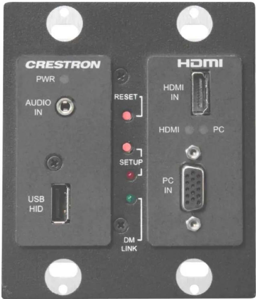
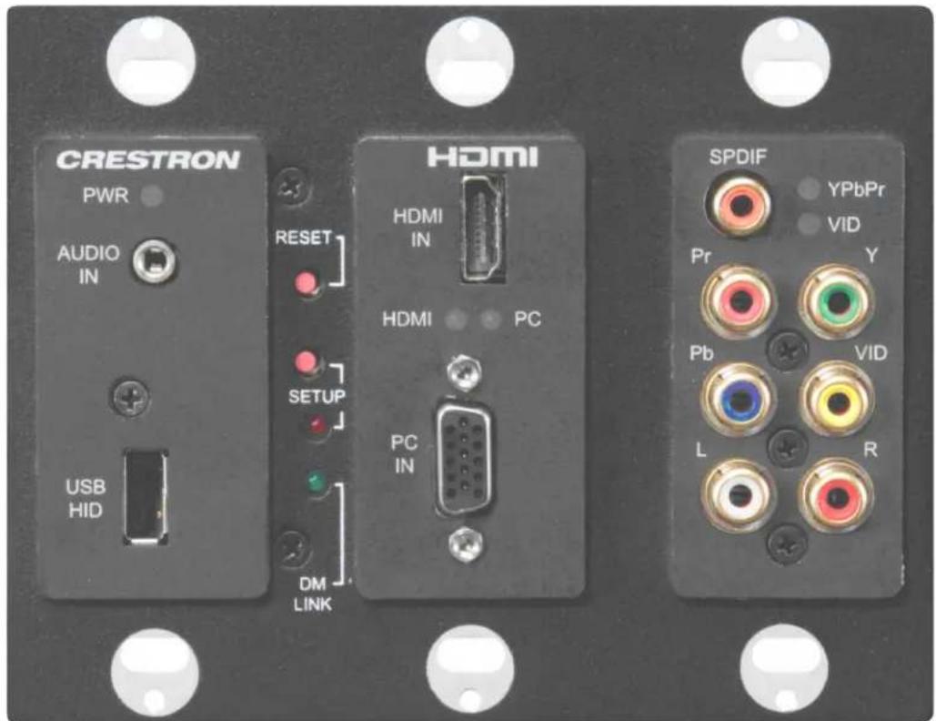
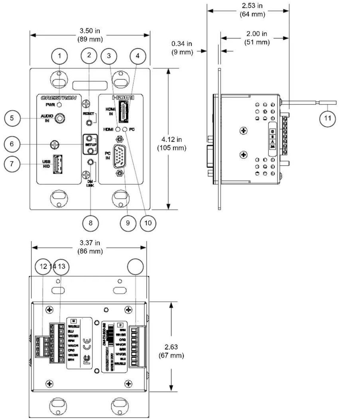
This section provides information on the connections, controls and indicators available on your DM-TX-200-2G and DM-TX-400-3G.
DM-TX-200-2G Physical View
DM-TX-400-3G Physical View
DM-TX-200-2G Overall Dimensions (Front, Right & Rear Views)
DM-TX-400-3G Overall Dimensions (Front, Right & Rear Views)
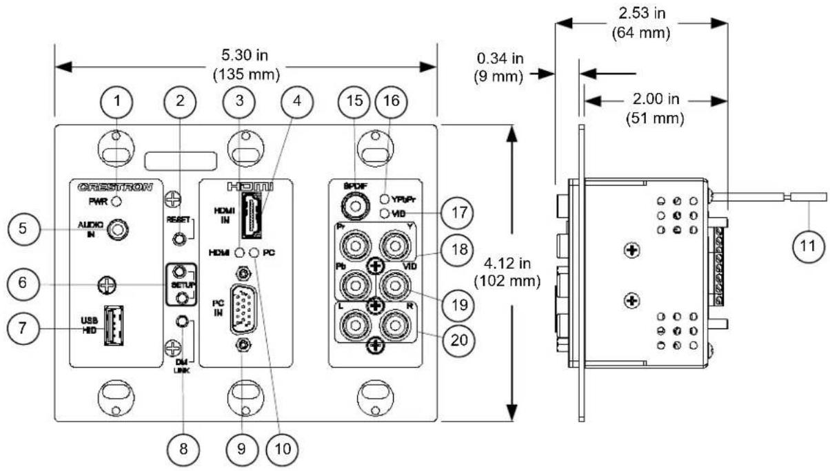
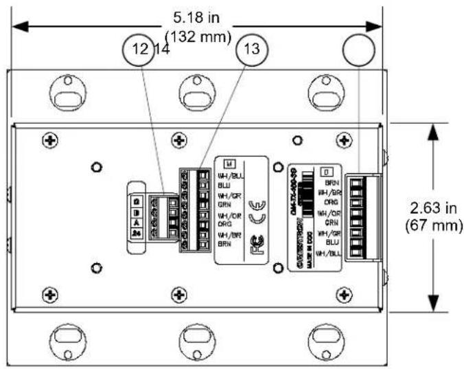
Connectors, Controls & Indicators
| # | CONNECTORS, CONTROLS & INDICATORS | DESCRIPTION |
| 1 | PWR | LED(1) Green LED, indicates operating power supplied via DMNet |
| 2 RESET | (1) Miniature recessed push button for hardware reset | |
| 3 | HDMI | LED(1) Green LED, indicates HDMI input is selected |
4 HDMI IN  | (1) 19-pin Type A HDMI female; HDMI digital video/audio input; Also supports DVI and DisplayPort Multimode ^1 | |
| 5 | AUDIO  | IN(1) 3.5 mm TRS mini phone jack; Unbalanced stereo line-level audio input; Input Impedance: 10k Ω; Input Level: 2 Vrms maximum |
| 6 | SETUP (LED and BUTTON) | (1) Red LED and (1) miniature recessed push button for Ethernet auto-discovery |
| 7 | USB  | HID(1) USB Type A female; USB 1.1 host port for connection of a mouse/keyboard or other USB HID-compliant device |
| 8 DM LINK LED | (1) Green LED, indicates connection to a downstream DM device | |
| 9 | PC 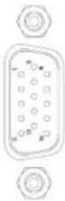 | IN(1) DB15HD female, RGB (VGA) or component (YP _b P _r ) video input ^2 ; Formats: RGBHV, RGBS, RG _s B, YP _b P _r ; Input Levels: 0.5 to 1.5 V _p-p with built-in DC restoration; Input Impedance: 75 Ω; Sync Input Type: Autodetect RGBHV, RGBS, RG _s B, YP _b P _r ; Sync Input Level: 3 to 5 V _p-p ; Sync Input Impedance: 1k Ω |
| 10 PC LED | (1) Green LED, indicates PC input is selected | |
| 11 GROUNDING WIRE (1) Flying lead, chassis ground connection ^3 | ||
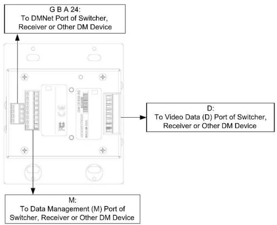
12 G B A 24 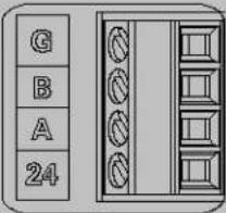 | (1) DMNet port composed of (4) captive screw terminals; Connects to DMNet port of a DM switcher, receiver/room controller, or other DM device via DM-CBL cable ^5,6 | |
| 13 | M 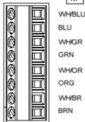 | (1) DM CAT output composed of (8) captive screw terminals with (1) grounded strain relief;Connects to DM CAT input of a DM switcher, receiver/room controller or other DM device via the yellow “M” cable of DM-CBL cable5;Uses the 568-B wiring standard. |
| 14 D | 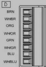 | (1) DM CAT output composed of (8) captive screw terminals with (1) grounded strain relief;Connects to “D” DM CAT input of a DM switcher, receiver/room controller or other DM device via the blue “D” cable of DM-CBL cable5;Uses the 568-B wiring standard. |
| 15 | SPDIF7 | (1) RCA female;S/PDIF coaxial digital audio input;Input Impedance: 75 Ω |
| 16 YP | bPrLED7 | (1) Green LED, indicates YPbPrinput is selected |
| 17 | VID7LED | (1) Green LED, indicates VID input is selected |
| 18 Y, P | b, Pr7 | (3) RCA female comprising (1) component (YPbPr) video input;Input Level: 1 Vp-p nominal;Input Impedance: 75 Ω nominal |
 | ||
| 19 | VID7 | (1) RCA female, composite video input;Input Level: 1 Vp-p nominal;Input Impedance: 75 Ω nominal |
| 20 L, R | 7 | (2) RCA female;Unbalanced stereo line-level audio input;Maximum Input: 2 Vrms;Input Impedance: 15k Ω |
-
HDMI requires an appropriate adapter or interface cable to accommodate a DVI or DisplayPort Multimode signal. CBL-HD-DVI and CBL-DP-HD interface cables available separately.
-
The RGB input can accept component, composite, and S-video signals via direct interface to Crestron MPS Series products, or through an appropriate adapter (not included). Input sync detection is not provided for composite or S-video signal types through the RGB connection.
-
A grounding lead is provided for connection to earth ground (building steel). This ground connection is recommended to provide a common ground reference for signals provided to the DM-TX-200-2G and DM-TX-400-3G, and to reduce the incidence of possible damage to the unit from static discharge.
-
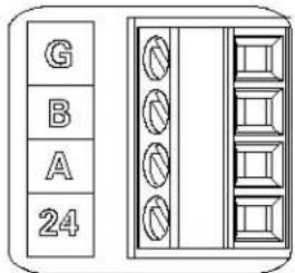
Refer to the following table for the G B A 24 connector pinouts.
| G B A 24 | |||
| PIN # SIGNAL DESCRIPTION WIRE COLOR | |||
| G | Ground | DC | Ground Black |
| B DMNet- DMNet Grey | |||
| A | DMNet+ | DMNet | Orange |
| 24 | 24V DC | DC Power | Red |
-
For DigitalMedia CAT wiring, use DM-CBL DigitalMedia Cable. Up to two DM Repeaters (Model DM-DR, sold separately) may be required. Refer to the latest version of the Crestron DigitalMedia Design Guide (Doc. 4789) for complete wiring guidelines.
-
DMNet wiring is not compatible with Cresnet wiring. DMNet wiring cannot be daisy chained.
-
DM-TX-400-3G only.
Setup
Network Wiring
When wiring the DM network, consider the following:
NOTE: DMNet wiring and Cresnet ^® wiring are not compatible.
- Use Crestron Certified Wire.
- Use Crestron power supplies for Crestron equipment.
- Provide sufficient power to the system.
CAUTION: Insufficient power can lead to unpredictable results or damage to the equipment. Please use the Crestron Power Calculator to help calculate how much power is needed for the system (www.crestron.com/calculators).
- For DigitalMedia CAT wiring, use DM-CBL DigitalMedia Cable. Up to two DM Repeaters (model DM-DR, sold separately) may be required. Refer to the latest version of the Crestron DigitalMedia Design Guide (Doc. 4789) for complete wiring guidelines.
For more details, refer to "Check Network Wiring" on page 34.
Identity Code
NOTE: In the SIMPL™ Windows program, when a DM-TX-200-2G or DM-TX-400-3G is dropped onto an input card of a DM switcher, its IP ID is assigned automatically and does not require additional programming. Use the information below when a DM-TX-200-2G or DM-TX-400-3G is dropped directly into an Ethernet slot on the control system in SIMPL Windows, without a DM switcher.
The IP ID is set within the DM-TX-200-2G's and DM-TX-400-3G's IP table using Crestron Toolbox. For information on setting an IP table, refer to the Crestron Toolbox help file. The IP IDs of multiple DM-TX-200-2G and DM-TX-400-3G devices in the same system must be unique.
When setting the IP ID, consider the following:
- The IP ID of each unit must match an IP ID specified in the SIMPL Windows program.
- Each device using IP to communicate with a control system must have a unique IP ID.
Auto-Detect Switching
The DM-TX-200-2G and DM-TX-400-3G can transmit a single audio and video source from a variety of inputs to the DM-CAT output.
By default, the DM-TX-200-2G and DM-TX-400-3G will auto-detect the highest priority active audio and video signal and route them to the DM-CAT output. The highest priority audio and video single will be transmitted together, with the only exception being that HDMI audio cannot be broken away from HDMI video. Refer to the chart below for default the A/V signal priority order.
NOTE: This configuration can be changed via Ethernet using Crestron Toolbox.
| PRIORITY | VIDEO | AUDIO |
| 1 HDMI | In HDMI in | |
| 2 PC In | Audio In^1 (1x 3.5 mm mini-TRS phone jack, analog input) | |
| 3 | Y, P_b, P_r (Component) ^2 | S/PDIF ^2 (1x RCA jack, coaxial digital input) |
| 4 Vid (Composite) | ^2L, R | ^2,3 (2x RCA analog input) |
- Audio will be transmitted from the 3.5 mm mini-TRS phone input based on the presence of a connector in the jack.
- DM-TX-400-3G only.
- If no audio signal is present, the default audio source will be the RCA analog inputs.
Supplied Hardware
The hardware supplied with the DM-TX-200-2G and DM-TX-400-3G is listed in the following tables.
Supplied Hardware for the DM-TX-200-2G
| DESCRIPTION | PART NUMBER | QUANTITY |
| Cable Clamp, Alum, 3/16" ID,0.813" x 0.375" x 0.250" | 2020120 | 1 |
| Cable Clamp, Alum, 1/4" ID,0.843" x 0.375" x 0.313" | 2026460 1 | |
| Nut, Keps, #06-32, External, Hex, Steel,Zinc | 2004883 | 2 |
| Screw, #06-32 x 3/4", Steel, Truss, ComboHead, Pilot .06", Zinc | 2009211 4 |
Supplied Hardware for the DM-TX-400-3G
| DESCRIPTION | PART NUMBER | QUANTITY |
| Cable Clamp, Alum, 3/16" ID, 0.813" x 0.375" x 0.250" | 2020120 | 2 |
| Cable Clamp, Alum, 1/4" ID, 0.843" x 0.375" x 0.313" | 2026460 2 | |
| Nut, Keps, #06-32, External, Hex, Steel, Zinc | 2004883 | 4 |
| Screw, #06-32 x 3/4", Steel, Truss, Combo Head, Pilot .06", Zinc | 2009211 6 |
Installation
To prevent overheating, do not operate this product in an area that exceeds the environmental temperature range listed in the table of specifications.
To install the DM-TX-200-2G or DM-TX-400-3G, the following tools and accessories are required:
- DM-CBL DigitalMedia Cable (sold separately). Refer to "Network Wiring" on page 16.
• Phillips screwdriver (not supplied) - Adjustable wrench (not supplied)
• Miniature flat head screwdriver (not supplied) -
06-32 x 3/4" oval head slotted screws (included) • Decorative style faceplate (not supplied)
An extra-deep electrical box is recommended (2 1/2 inches (64 mm) deep minimum). It is assumed that the required cable has been fed through an installed 2-gang or 3-gang electrical box (not supplied), and wiring has been verified.
- Confirm that DMNet system power is OFF.
- Strip 3 3/4 inches (95 mm) of the DigitalMedia Cable to expose the three inner cables.
- Strip the outer jacket of the blue "D" cable 2 1/2 inches (64 mm) from end. Gather and twist the wire braid. Refer to the following illustration.
"D" Cable (Stripping the Outer Jacket)
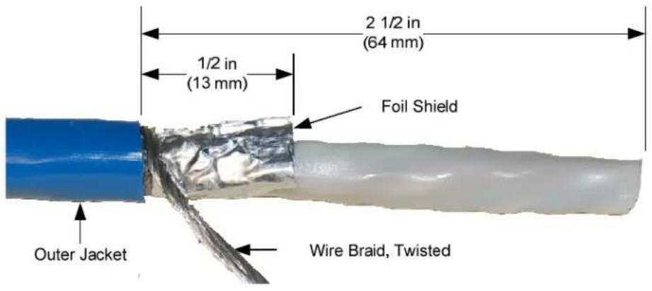
- Trim foil shield to 1/2 inch (13 mm).
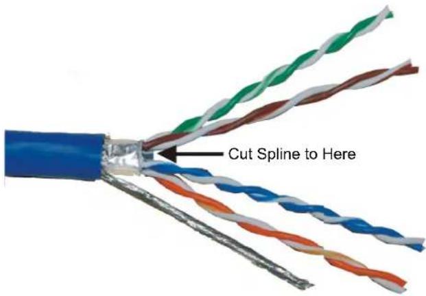
- Remove the white neoprene sheath and separate the twisted pairs to expose the spline. Cut the spline so it is near flush with the foil shield as shown in the following illustration. Return twisted pairs to original position.
"D" Cable (Cutting the Spline)
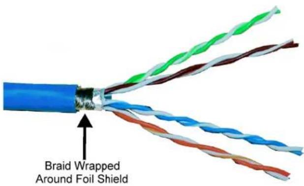
- Neatly wrap the twisted braid around the foil shield as shown in the following illustration. Only the silver side of foil shield is conductive.
NOTE: Braid should wind neatly around foil shield. Loose braid may cause shorts.
"D" Cable (Wrapping the Twisted Braid)
- Strip the insulation from the ends of each wire, exposing approximately 3/16 inch (5 mm) of bare copper.
NOTE: Do not allow the twisted pairs to untwist for more than 1/2 inch (13 mm).
NOTE: Maintain equal wire lengths within 1/8 inch (3 mm).
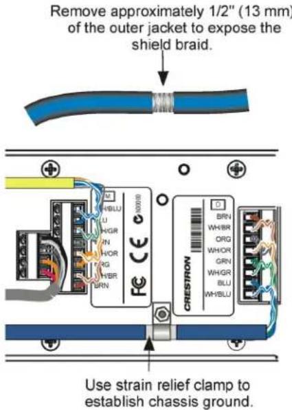
- Using an adjustable wrench, clamp the prepared cable to the unit as shown in the following illustration.
NOTE: Twisted braid and foil shield must be in full contact with inside of clamp.
Clamping the Cable to the Unit
- Strip the outer jacket of the yellow "M" cable 2 inches (51 mm) from end.
- Strip the insulation from the ends of each wire, exposing approximately 3/16 inch (5 mm) of bare copper.
- Using a miniature flat head screwdriver (not supplied), make the connections as specified, using the labels on the unit as a guide.
a. Insert the twisted pairs of the gray DMNet cable into the G B A 24 terminal block and tighten each screw base. Refer to footnote #4 on page 15 for details.
G B A 24 Terminal Block
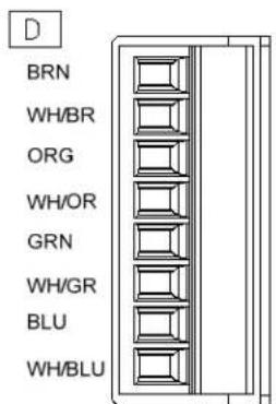
b. Insert the twisted pairs of the blue, shielded cable into the D terminal block and tighten each screw base. Use the 568-B wiring standard.
D Terminal Block
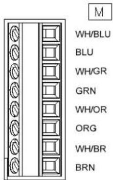
c. Insert the twisted pairs of the yellow, unshielded cable into the M terminal block and tighten each screw base. Use the 568-B wiring standard.
M Terminal Block
- Remove the pre-cut insulation from the grounding wire and connect it to the electrical box or a ground wire in the electrical box (the electrical box must be earth grounded).
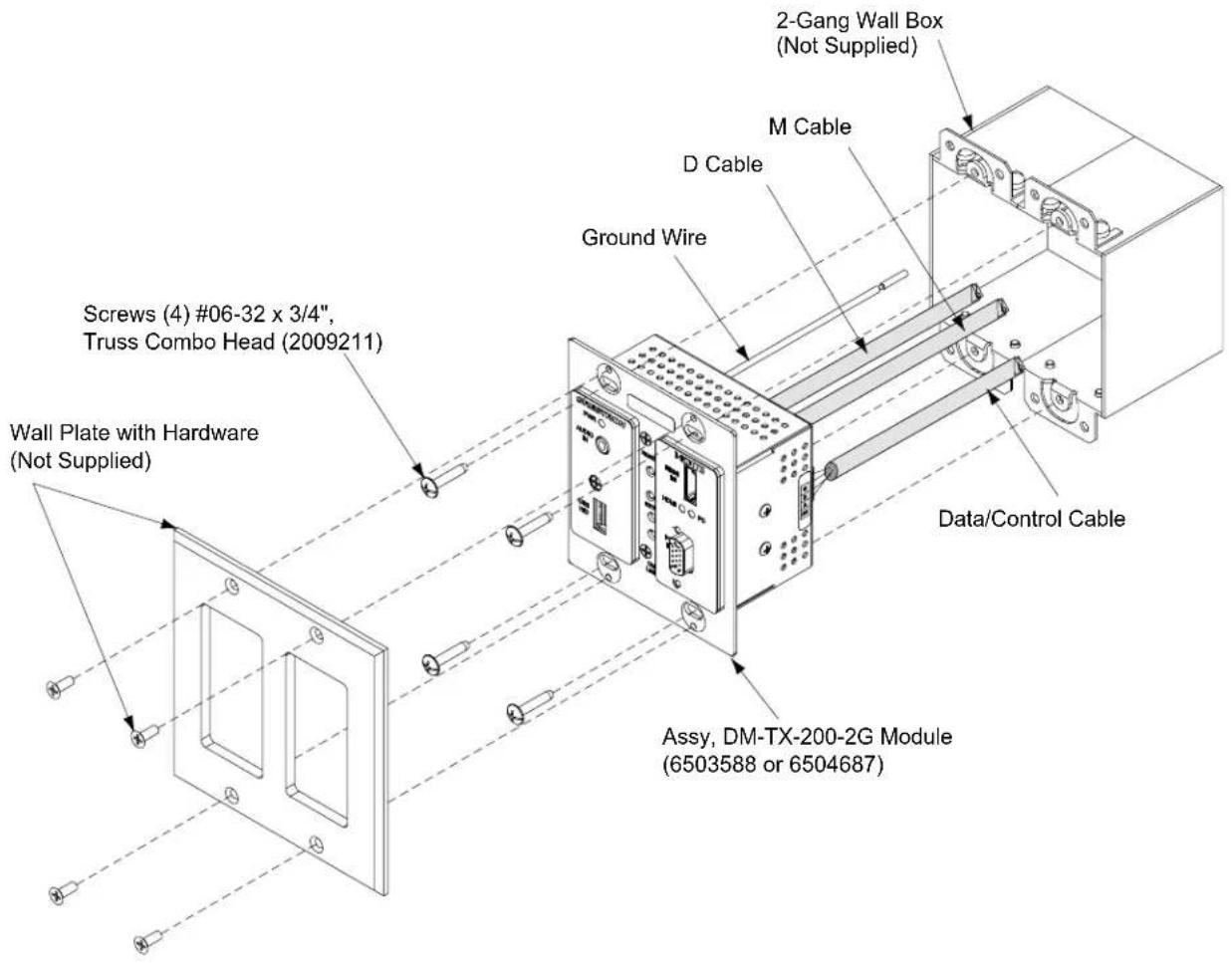
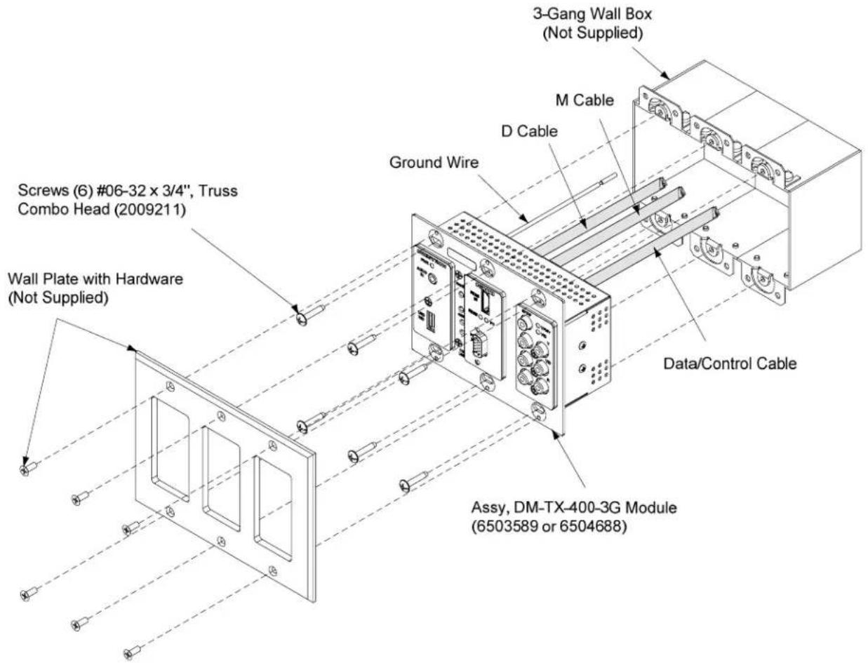
- Attach the unit to the electrical box using the included #06-32 x 3/4" oval head slotted screws as shown in the illustration on the following two pages.
CAUTION: Excess wire pinched between the unit and electrical box could cause a short. Make sure that all excess wire is completely inside the electrical box and not between the box and the side of the unit.
- Attach an appropriate decorative style faceplate (not supplied).
DM-TX-200-2G in a 2-Gang Box (Exploded View)
DM-TX-400-3G in a 3-Gang Box (Exploded View)
Hardware Hookup
Connect the Device
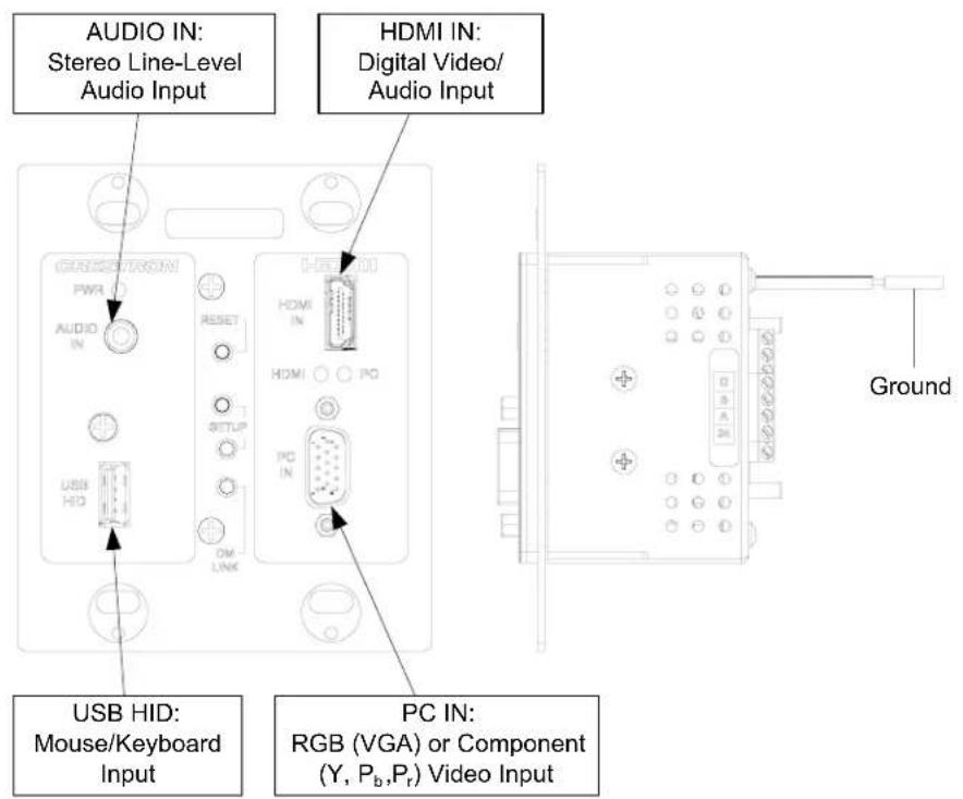
Make the necessary connections as called out in the illustration that follows this paragraph. Refer to "Network Wiring" on page 16 before attaching the DMNet Cable. Apply power after all connections have been made.
When making connections to the DM-TX-200-2G and DM-TX-400-3G, use Crestron power supplies for Crestron equipment.
Hardware Connections for the DM-TX-200-2G
Hardware Connections for the DM-TX-400-3G
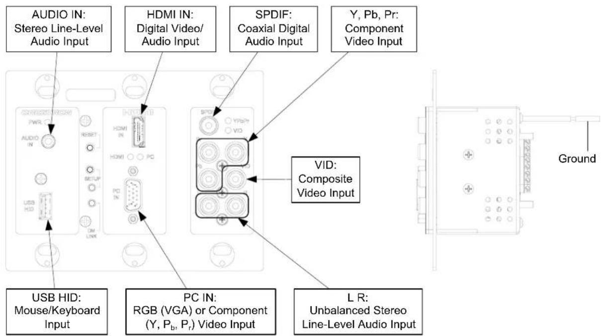
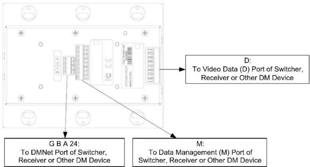
NOTE: Ensure the unit is properly grounded by connecting the chassis ground lug to an earth ground (building steel).
NOTE: To prevent overheating, do not operate this product in an area that exceeds the environmental temperature range listed in the table of specifications.
NOTE: For optimum performance, Crestron requires using DM-CBL DigitalMedia cable, available from Crestron.
NOTE: The minimum cable length required for DM-CBL DigitalMedia cable is 15 feet (\~4.6 meters).
Programming Software
Have a question or comment about Crestron software?
Answers to frequently asked questions (FAQs) can be viewed in the Online Help section of the Crestron Web site. To post a question or view questions you have submitted to Crestron's True Blue Support, log in at www.crestron.com/support. First-time users will need to establish a user account.
Earliest Version Software Requirements for the PC
NOTE: Crestron recommends that you use the latest software to take advantage of the most recently released features. The latest software is available from the Crestron Web site (www.crestron.com/software).
Crestron provides an assortment of Windows ^® -based software tools to develop a customized system. Use Crestron SystemBuilder ^™ or SIMPL Windows to create a program to control the DM-TX-200-2G or DM-TX-400-3G.
Programming with Crestron SystemBuilder
Crestron SystemBuilder is the easiest method of programming but does not offer as much flexibility as SIMPL Windows. For additional details, download SystemBuilder from the Crestron Web site and examine the extensive help file.
Programming with SIMPL Windows
NOTE: While SIMPL Windows can be used to program the DM-TX-200-2G or DM-TX-400-3G, it is recommended to use SystemBuilder for configuring a system.
SIMPL Windows is Crestron's premier software for programming Crestron control systems. It is organized into two separate but equally important “Managers”: Configuration and Program.
Configuration Manager
Configuration Manager is the view where programmers “build” a Crestron control system by selecting hardware from the Device Library.
-
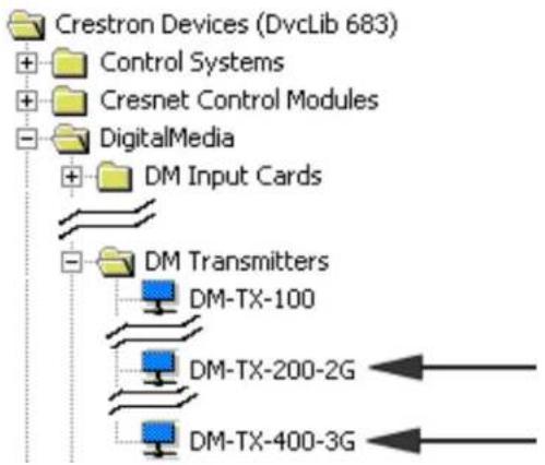
To incorporate the DM-TX-200-2G or DM-TX-400-3G into the system, drag the DM-TX-200-2G or DM-TX-400-3G from the DigitalMedia | DM Transmitters folder of the Device Library and drop it into either of the following System Views:
-
A compatible input card of a DM switcher
- Directly to a card in the Ethernet slot of the control system (used without a DM switcher)
Locating the DM-TX-200-2G and DM-TX-400-3G in the Device Library
flowchart
graph TD
    A["Crestron Devices (DvcLib 683)"] --> B["Control Systems"]
    B --> C["Cresnet Control Modules"]
    C --> D["DigitalMedia"]
    D --> E["DM Input Cards"]
    E --> F["DM Transmitters"]
    F --> G["DM-TX-100"]
    F --> H["DM-TX-200-2G"]
    F --> I["DM-TX-400-3G"]
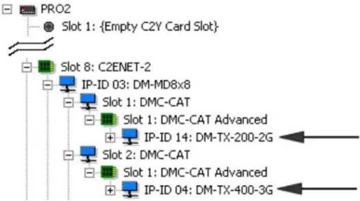
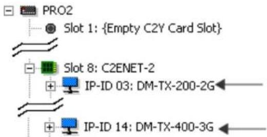
The system tree of the control system displays the DM-TX-200-2G and DM-TX-400-3G in the appropriate slot with a default IP ID as shown in the following illustrations. In the first example, the DM-TX-200-2G and DM-TX-400-3G is used with the DMC-CAT input card in a DM-MD8X8 switcher (both sold separately). In the second example, the DM-TX-200-2G and DM-TX-400-3G is used with the C2ENET-2 card (sold separately) in an Ethernet slot on the control system.
C2ENET-2 Device, Slot 8 (Using Input Card in a DM Switcher)
flowchart
graph TD
    A["PRO2"] --> B["Slot 1: {Empty C2Y Card Slot}"]
    B --> C["Slot 8: C2ENET-2"]
    C --> D["IP-ID 03: DM-MD8x8"]
    D --> E["Slot 1: DMC-CAT"]
    E --> F["Slot 1: DMC-CAT Advanced"]
    F --> G["IP-ID 14: DM-TX-200-2G"]
    G --> H["Slot 2: DMC-CAT"]
    H --> I["Slot 1: DMC-CAT Advanced"]
    I --> J["IP-ID 04: DM-TX-400-3G"]
C2ENET-2 Device, Slot 8 (Using Ethernet Slot on Control System)
-
If additional DM-TX-200-2G or DM-TX-400-3G devices are to be added, repeat step 1 for each device. Each DM-TX-200-2G and DM-TX-400-3G device is assigned a different IP ID.
-
If necessary, double click a device to open the "Device Settings" dialog box and change the IP ID as shown in the following figure (DM-TX-200-2G shown).
"Device Settings: Crestron DM-TX-200-2G" Dialog Box
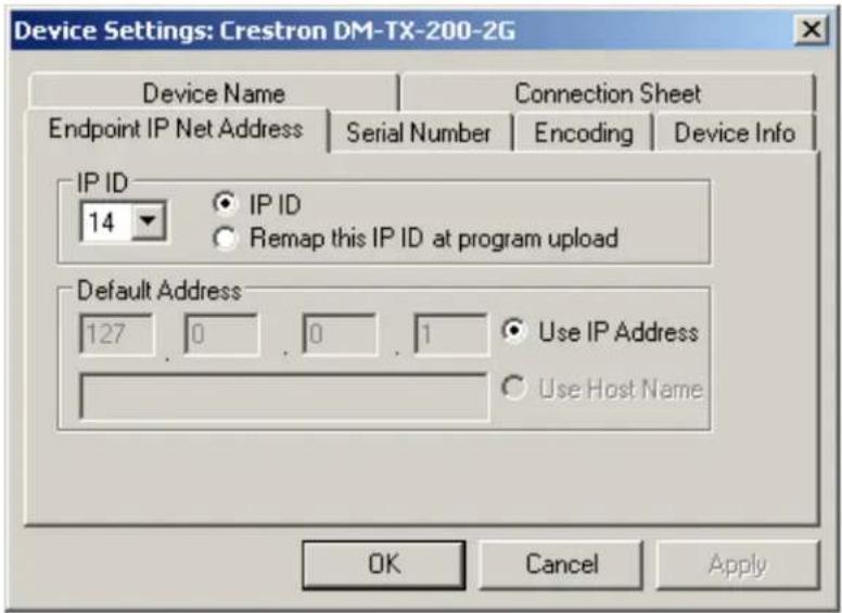
NOTE: The ID code specified in the SIMPL Windows program must match the IP ID of each unit. Refer to "Identity Code" on page 16.
Program Manager
Program Manager is the view where programmers "program" a Crestron control system by assigning signals to symbols.
The symbol can be viewed by double clicking on the icon or dragging it into Detail View. Each signal in the symbol is described in the SIMPL Windows help file (F1).
Uploading and Upgrading
Crestron recommends using the latest programming software and that each device contains the latest firmware to take advantage of the most recently released features. However, before attempting to upload or upgrade it is necessary to establish communication. Once communication has been established, files (for example, firmware) can be transferred to the control system (and/or device). In addition, the IP table of the device can be configured
Establishing Communication
Use Crestron Toolbox for communicating with the DM-TX-200-2G or DM-TX-400-3G refer to the Crestron Toolbox help file for details.
A PC running Crestron Toolbox communicates with the DM-TX-200-2G or DM-TX-400-3G in the following ways:
- Via a DM switcher using TCP/IP or USB communication. TCP/IP provides a faster method of communication than USB.
• Via a DM-RMC-100 using TCP/IP communication.
Via DM Switcher
TCP/IP Communication via DM Switcher

flowchart
graph LR
    A["PC Running Crestron Toolbox"] <-->|LAN| B["DM Switcher"]
    B <-->|ETHERNET| C["DM-TX-200-2G or DM-TX-400-3G"]
To establish TCP/IP communication between the PC and the DM-TX-200-2G or DM-TX-400-3G via a DM switcher:
- Establish communication between the PC and the DM switcher as described in the latest version of the Digital Media Switchers Operations Guide (Doc. 6755).
- Use the Device Discovery Tool in Crestron Toolbox to find the IP address of the DM-TX-200-2G or DM-TX-400-3G. The tool is available in Toolbox version 1.15.143 or later.
- Use the Address Book in Crestron Toolbox to create an entry for the DM-TX-200-2G or DM-TX-400-3G using the TCP connection type and enter the IP address of the DM-TX-200-2G or DM-TX-400-3G.
- Display the DM-TX-200-2G or DM-TX-400-3G's "System Info" window (click the i icon); communications are confirmed when the device information is displayed.
USB Communication via DM Switcher

flowchart
graph LR
    A["PC Running Crestron Toolbox"] <-->|USB| B["DM Switcher"]
    B <-->|DMNet| C["DM-TX-200-2G or DM-TX-400-3G"]
To establish USB communication between the PC and the DM-TX-200-2G or DM-TX-400-3G via a DM switcher:
- Use the Address Book in Crestron Toolbox to create an entry using the expected communication protocol (USB). When multiple USB devices are connected, identify the DM switcher by entering "DM-MD8X8", "DM-MD16X16" or "DM-MD32X32" in the Model textbox, the unit's serial number in the Serial textbox or the unit's hostname in the Hostname textbox. The hostname can be sound in the "System Info" window in the Ethernet section of the window, however, communication must be established in order to see this information in the "System Info" window.
- Display the DM-TX-200-2G or DM-TX-400-3G's "System Info" window (click the i icon); communications are confirmed when the device information is displayed.
Via DM-RMC-100
TCP/IP Communication via DM-RMC-100

flowchart
graph LR
    A["PC Running Crestron Toolbox"] <--> B["LAN"]
    B --> C["DM-RMC-100"]
    C <--> D["DM-TX-200-2G or DM-TX-400-3G"]
    D --> C
    C --> E["ETHERNET"]
The DM-TX-200-2G or DM-TX-400-3G connects to PC via Ethernet:
- Confirm Ethernet connection between DM-RMC-100 and PC. If connecting through a hub or router, use CAT5 straight through cables with 8-pin RJ-45 connectors. Alternatively, use a CAT5 crossover cable to connect the two LAN ports directly without using a hub or router.
- By default, DHCP is enabled. Use the Device Discovery Tool in Crestron Toolbox to find the IP address of the DM-TX-200-2G or DM-TX-400-3G. To change the IP configuration, from Crestron Toolbox, display the "System Info" window (click the icon) and select the DM-TX-200-2G or DM-TX-400-3G entry from the Address Book. Select Functions | Ethernet Addressing and enter the new IP address, IP mask and default router of the DM-TX-200-2G or DM-TX-400-3G.
NOTE: If the DM-TX-200-2G is in a non-DHCP environment, a default IP address (192.168.1.232) can be assigned by holding down its SETUP button while applying power. If the DM-TX-400-3G is in a non-DHCP environment, a default IP address (192.168.1.235) can be assigned by holding down its SETUP button while applying power. This IP address will overwrite any previous settings and will remain until it is changed.
-
Use the Address Book in Crestron Toolbox to create an entry for the DM-TX-200-2G or DM-TX-400-3G with the DM-TX-200-2G's or DM-TX-400-3G's TCP/IP communication parameters.
-
Display the "System Info" window (click the icon) and select the DM-TX-200-2G or DM-TX-400-3G entry from the Address Book.
Firmware
Firmware files may be distributed from programmers to installers or from Crestron to dealers. Firmware upgrades are available from the Crestron Web site as new features are developed after product releases. For details on upgrading, refer to the Crestron Toolbox help file.
Check the Crestron Web site to find the latest firmware. (New users may be required to register to obtain access to certain areas of the site, including the FTP site.)
To upgrade the DM-TX-200-2G or DM-TX-400-3G's firmware:
-
Do either of the following
-
If the DM-TX-200-2G or DM-TX-400-3G is connected to a DM switcher, use the Device Discovery Tool in Crestron Toolbox to find the IP address of the switcher.
-
If the DM-TX-200-2G or DM-TX-400-3G is being used in standalone configuration (i.e., without a DM switcher), use the Device Discovery Tool to find the IP address of the DM-TX-200-2G or DM-TX-400-3G.
-
Add the IP address to the Address Book in Toolbox.
-
Download the appropriate .puf file from the Crestron Web site to your PC.
-
Double-click the .puf file. The Toolbox Address Book opens.
-
From the list in the Address Book, select the DM switcher (if the DM-TX-200-2G or DM-TX-400-3G is connected to a switcher) or the DM-TX-200-2G or DM-TX-400-3G (if the DM-TX-200-2G or DM-TX-400-3G is used in a standalone configuration), and then click OK.
Either of the following occurs:
- If the DM switcher was selected, a DM device list is displayed that allows upgrading all DM devices connected to the switcher.
- If the DM-TX-200-2G or DM-TX-400-3G was selected, a DM device list is displayed that allows upgrading of the DM-TX-200-2G or DM-TX-400-3G only.
In the DM device lists that are displayed, the checkbox of any item that needs to be upgraded is automatically selected.
-
Click Update.
-
After the process is complete, click Recheck to verify the upgrade.
IP Configuration
If the DM-TX-200-2G or DM-TX-400-3G is used in a standalone configuration (i.e., without a DM switcher), use Crestron Toolbox to create the IP table entry for the DM-TX-200-2G or DM-TX-400-3G.
NOTE: If the DM-TX-200-2G or DM-TX-400-3G is connected directly to a DM switcher, the IP table entry for the DM-TX-200-2G or DM-TX-400-3G is created automatically.
- Use the Device Discovery Tool in Crestron Toolbox to find the IP address of the DM-TX-200-2G or DM-TX-400-3G. Then, display the "System Info" window (click the icon) and select the DM-TX-200-2G or DM-TX-400-3G entry from the Address Book.
- Select Functions | IP Table Setup.
- Add, modify or delete entries in the IP table. The DM-TX-200-2G or DM-TX-400-3G can have only one IP table entry.
- A defined IP table can be saved to a file or sent to the device.
DMTool
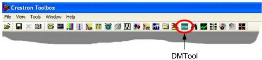
In the Crestron Toolbox Address Book, select the DM-TX-200-2G or DM-TX-400-3G. Then use the DMTool to configure EDID, HDCP or to troubleshoot AV on the DM-TX-200-2G or DM-TX-400-3G. Refer to the help file for additional information.
DMTool
Problem Solving
Troubleshooting
The following table provides corrective action for possible trouble situations. If further assistance is required, please contact a Crestron customer service representative.
DM-TX-200-2G and DM-TX-400-3G Troubleshooting
| TROUBLE POSSIBLE CAUSE(S) CORRECTIVE ACTION | ||
| Device does not function. | Device is not communicating with the network. | Use Crestron Toolbox to poll the network. Verify network connection to the device. |
| Device is not receiving power from a Crestron power source. | Use the provided Crestron power source. Verify connections. | |
| Device is not receiving sufficient power. | Use the Crestron Power Calculator to help calculate how much power is needed for the system. | |
| PWR LED does not illuminate. | Device is not receiving power. | Verify that DMNet is properly attached. |
| DM LINK LED does not illuminate. | Device is not transmitting DMNet signal. | Verify that DM connections are properly attached. |
| Source LED's do not illuminate. | Sources are not transmitting signals. | Verify source operation. |
| Intermittent or no audio output. | Poor cable connection. | Verify all cable connections. |
| Loss of functionality due to electrostatic discharge. | Improper grounding. | Check that all ground connections have been made properly. |
NOTE: For more advanced diagnostics, use the DMTool in Crestron Toolbox.
Check Network Wiring
Use the Right Wire
In order to ensure optimum performance over the full range of your installation topology, Crestron Certified Wire and only Crestron Certified Wire may be used. Failure to do so may incur additional charges if support is required to identify performance deficiencies because of using improper wire.
Calculate Power
CAUTION: Use only Crestron power supplies for Crestron equipment. Failure to do so could cause equipment damage or void the Crestron warranty.
CAUTION: Provide sufficient power to the system. Insufficient power can lead to unpredictable results or damage to the equipment. The EIG connector on the DM switcher is used to bring in external power. Additional power is rarely required as switchers provide enough power for their maximum configuration of room controllers and repeaters. Please use the DMNet Power Calculator to help calculate how much power is needed for the system (www.crestron.com/calculators).
Refer to the following table for commonly used resolutions and maximum DM-CBL cable lengths.
Commonly Used Resolutions and Maximum DM Cable Length
| DM-CBL CABLE LENGTH | ||
| RESOLUTION | Maximum length without, between, before, or after repeaters | Maximum total length using up to 2 repeaters |
| 720p, 1080i, 1080p/24 200 ft (60 m) | 450 ft (137 m) | |
| 1024 x 768 @75 Hz 200 ft (60 m) 450 ft (137 m) | ||
| 1080p/60 150 ft (45 m) 450 ft (137 m) | ||
| 1280 x 1024 @ 75 Hz 150 ft (45 m) 450 ft (137 m) | ||
| 1920 x 1200 @ 60 Hz 150 ft (45 m) 450 ft (137 m) | ||
| 1600 x 1200 @ 60 Hz 125 ft (38 m) 375 ft (114 m) | ||
| 1080p/60 Deep Color Not Supported | ||
NOTE: 1080p @ 60 Hz is the most common resolution used in residential installations.
NOTE: All Crestron certified DMNet wiring must consist of two twisted pairs. One twisted pair is the +24V conductor and the GND conductor and the other twisted pair is the A conductor and the B conductor.
Reference Documents
The latest version of all documents mentioned within the guide can be obtained from the Crestron Web site.
List of Related Reference Documents
DOCUMENT TITLE
Crestron DigitalMedia Design Guide (www.crestron.com/dmresources)
Crestron DigitalMedia Switchers Operations Guide (www.crestron.com/manuals)
Further Inquiries
If you cannot locate specific information or have questions after reviewing this guide, please take advantage of Crestron's award winning customer service team by calling Crestron at 1-888-CRESTRON [1-888-273-7876].
You can also log onto the online help section of the Crestron Web site (www.crestron.com/onlinehelp) to ask questions about Crestron products. First-time users will need to establish a user account to fully benefit from all available features.
Future Updates
As Crestron improves functions, adds new features and extends the capabilities of the DM-TX-200-2G and DM-TX-400-3G, additional information may be made available as manual updates. These updates are solely electronic and serve as intermediary supplements prior to the release of a complete technical documentation revision.
Check the Crestron Web site periodically for manual update availability and its relevance. Updates are identified as an “Addendum” in the Download column.
Return and Warranty Policies
Merchandise Returns / Repair Service
- No merchandise may be returned for credit, exchange or service without prior authorization from CRESTRON. To obtain warranty service for CRESTRON products, contact an authorized CRESTRON dealer. Only authorized CRESTRON dealers may contact the factory and request an RMA (Return Merchandise Authorization) number. Enclose a note specifying the nature of the problem, name and phone number of contact person, RMA number and return address.
- Products may be returned for credit, exchange or service with a CRESTRON Return Merchandise Authorization (RMA) number. Authorized returns must be shipped freight prepaid to CRESTRON, 6 Volvo Drive, Rockleigh, N.J. or its authorized subsidiaries, with RMA number clearly marked on the outside of all cartons. Shipments arriving freight collect or without an RMA number shall be subject to refusal. CRESTRON reserves the right in its sole and absolute discretion to charge a 15% restocking fee plus shipping costs on any products returned with an RMA.
- Return freight charges following repair of items under warranty shall be paid by CRESTRON, shipping by standard ground carrier. In the event repairs are found to be non-warranty, return freight costs shall be paid by the purchaser.
CRESTRON Limited Warranty
CRESTRON ELECTRONICS, Inc. warrants its products to be free from manufacturing defects in materials and workmanship under normal use for a period of three (3) years from the date of purchase from CRESTRON, with the following exceptions: disk drives and any other moving or rotating mechanical parts, pan/tilt heads and power supplies are covered for a period of one (1) year; touchscreen display and overlay components are covered for 90 days; batteries and incandescent lamps are not covered.
This warranty extends to products purchased directly from CRESTRON or an authorized CRESTRON dealer. Purchasers should inquire of the dealer regarding the nature and extent of the dealer's warranty, if any.
CRESTRON shall not be liable to honor the terms of this warranty if the product has been used in any application other than that for which it was intended or if it has been subjected to misuse, accidental damage, modification or improper installation procedures. Furthermore, this warranty does not cover any product that has had the serial number altered, defaced or removed.
This warranty shall be the sole and exclusive remedy to the original purchaser. In no event shall CRESTRON be liable for incidental or consequential damages of any kind (property or economic damages inclusive) arising from the sale or use of this equipment. CRESTRON is not liable for any claim made by a third party or made by the purchaser for a third party.
CRESTRON shall, at its option, repair or replace any product found defective, without charge for parts or labor. Repaired or replaced equipment and parts supplied under this warranty shall be covered only by the unexpired portion of the warranty.
Except as expressly set forth in this warranty, CRESTRON makes no other warranties, expressed or implied, nor authorizes any other party to offer any warranty, including any implied warranties of merchantability or fitness for a particular purpose. Any implied warranties that may be imposed by law are limited to the terms of this limited warranty. This warranty statement supersedes all previous warranties.
GNU General Public License
Version 2, June 1991
Copyright (C) 1989, 1991 Free Software Foundation, Inc., 51 Franklin Street, Fifth Floor, Boston, MA 02110-1301 USA Everyone is permitted to copy and distribute verbatim copies of this license document but changing it is not allowed.
PREAMBLE
The licenses for most software are designed to take away your freedom to share and change it. By contrast, the GNU General Public License is intended to guarantee your freedom to share and change free software--to make sure the software is free for all its users. This General Public License applies to most of the Free Software Foundation's software and to any other program whose authors commit to using it. (Some other Free Software Foundation software is covered by the GNU Lesser General Public License instead.) You can apply it to your programs too.
When we speak of free software, we are referring to freedom, not price. Our General Public Licenses are designed to make sure that you have the freedom to distribute copies of free software (and charge for this service if you wish), that you receive source code or can get it if you want it, that you can change the software or use pieces of it in new free programs and that you know you can do these things.
To protect your rights, we need to make restrictions that forbid anyone to deny you these rights or to ask you to surrender the rights. These restrictions translate to certain responsibilities for you if you distribute copies of the software or if you modify it.
For example, if you distribute copies of such a program, whether gratis or for a fee, you must give the recipients all the rights that you have. You must make sure that they too receive or can get the source code. And you must show them these terms so they know their rights.
We protect your rights with two steps: (1) copyright the software, and (2) offer you this license which gives you legal permission to copy, distribute and/or modify the software.
Also, for each author's protection and ours, we want to make certain that everyone understands that there is no warranty for this free software. If the software is modified by someone else and passed on, we want its recipients to know that what they have is not the original, so that any problems introduced by others will not reflect on the original authors' reputations.
Finally, any free program is threatened constantly by software patents. We wish to avoid the danger that redistributors of a free program will individually obtain patent licenses, in effect making the program proprietary. To prevent this, we have made it clear that any patent must be licensed for everyone's free use or not licensed at all.
The precise terms and conditions for copying, distribution and modification follow.
GNU GENERAL PUBLIC LICENSE TERMS AND CONDITIONS FOR COPYING, DISTRIBUTION AND MODIFICATION
- This License applies to any program or other work which contains a notice placed by the copyright holder saying it may be distributed under the terms of this General Public License. The "Program" below refers to any such program or work, and a "work based on the Program" means either the Program or any derivative work under copyright law: that is to say, a work containing the Program or a portion of it, either verbatim or with modifications and/or translated into another language. (Hereinafter, translation is included without limitation in the term "modification".) Each licensee is addressed as "you".
Activities other than copying, distribution and modification are not covered by this License; they are outside its scope. The act of running the Program is not restricted, and the output from the Program is covered only if its contents constitute a work based on the Program (independent of having been made by running the Program). Whether that is true depends on what the Program does.
- You may copy and distribute verbatim copies of the Program's source code as you receive it, in any medium, provided that you conspicuously and appropriately publish on each copy an appropriate copyright notice and disclaimer of warranty; keep intact all the notices that refer to this License and to the absence of any warranty; and give any other recipients of the Program a copy of this License along with the Program.
You may charge a fee for the physical act of transferring a copy and you may at your option offer warranty protection in exchange for a fee.
- You may modify your copy or copies of the Program or any portion of it, thus forming a work based on the Program, and copy and distribute such modifications or work under the terms of Section 1 above, provided that you also meet all of these conditions:
a) You must cause the modified files to carry prominent notices stating that you changed the files and the date of any change.
b) You must cause any work that you distribute or publish, that in whole or in part contains or is derived from the Program or any part thereof, to be licensed as a whole at no charge to all third parties under the terms of this License.
c) If the modified program normally reads commands interactively when run, you must cause it, when started running for such interactive use in the most ordinary way, to print or display an announcement including an appropriate copyright notice and a notice that there is no warranty (or else, saying that you provide a warranty) and that users may redistribute the program under these conditions, and telling the user how to view a copy of this License. (Exception: if the Program itself is interactive but does not normally print such an announcement, your work based on the Program is not required to print an announcement.)
These requirements apply to the modified work as a whole. If identifiable sections of that work are not derived from the Program and can be reasonably considered independent and separate works in themselves, then this License and its terms do not apply to those sections when you distribute them as separate works. But when you distribute the same sections as part of a whole which is a work based on the Program, the distribution of the whole must be on the terms of this License, whose permissions for other licensees extend to the entire whole and thus to each and every part regardless of who wrote it.
Thus, it is not the intent of this section to claim rights or contest your rights to work written entirely by you; rather, the intent is to exercise the right to control the distribution of derivative or collective works based on the Program.
In addition, mere aggregation of another work not based on the Program with the Program (or with a work based on the Program) on a volume of a storage or distribution medium does not bring the other work under the scope of this License.
- You may copy and distribute the Program (or a work based on it, under Section 2) in object code or executable form under the terms of Sections 1 and 2 above provided that you also do one of the following:
a) Accompany it with the complete corresponding machine-readable source code, which must be distributed under the terms of Sections 1 and 2 above on a medium customarily used for software interchange; or,
b) Accompany it with a written offer, valid for at least three years, to give any third party, for a charge no more than your cost of physically performing source distribution, a complete machine-readable copy of the corresponding source code, to be distributed under the terms of Sections 1 and 2 above on a medium customarily used for software interchange; or,
c) Accompany it with the information you received as to the offer to distribute corresponding source code. (This alternative is allowed only for noncommercial distribution and only if you received the program in object code or executable form with such an offer, in accord with Subsection b above.)
The source code for a work means the preferred form of the work for making modifications to it. For an executable work, complete source code means all the source code for all modules it contains, plus any associated interface definition files, plus the scripts used to control compilation and installation of the executable. However, as a special exception, the source code distributed need not include anything that is normally distributed (in either source or binary form) with the major components (compiler, kernel and so on) of the operating system on which the executable runs, unless that component itself accompanies the executable.
If distribution of executable or object code is made by offering access to copy from a designated place, then offering equivalent access to copy the source code from the same place counts as distribution of the source code, even though third parties are not compelled to copy the source along with the object code.
-
You may not copy, modify, sublicense or distribute the Program except as expressly provided under this License. Any attempt otherwise to copy, modify, sublicense or distribute the Program is void and will automatically terminate your rights under this License. However, parties who have received copies or rights, from you under this License will not have their licenses terminated so long as such parties remain in full compliance.
-
You are not required to accept this License, since you have not signed it. However, nothing else grants you permission to modify or distribute the Program or its derivative works. These actions are prohibited by law if you do not accept this License. Therefore, by
modifying or distributing the Program (or any work based on the Program), you indicate your acceptance of this License to do so and all its terms and conditions for copying, distributing or modifying the Program or works based on it.
-
Each time you redistribute the Program (or any work based on the Program), the recipient automatically receives a license from the original licensor to copy, distribute or modify the Program subject to these terms and conditions. You may not impose any further restrictions on the recipients' exercise of the rights granted herein. You are not responsible for enforcing compliance by third parties to this License.
-
If, as a consequence of a court judgment or allegation of patent infringement or for any other reason (not limited to patent issues), conditions are imposed on you (whether by court order, agreement or otherwise) that contradict the conditions of this License, they do not excuse you from the conditions of this License. If you cannot distribute so as to satisfy simultaneously your obligations under this License and any other pertinent obligations, then as a consequence you may not distribute the Program at all. For example, if a patent license would not permit royalty-free redistribution of the Program by all those who receive copies directly or indirectly through you, then the only way you could satisfy both it and this License would be to refrain entirely from distribution of the Program.
If any portion of this section is held invalid or unenforceable under any particular circumstance, the balance of the section is intended to apply and the section as a whole is intended to apply in other circumstances.
It is not the purpose of this section to induce you to infringe any patents or other property right claims or to contest validity of any such claims; this section has the sole purpose of protecting the integrity of the free software distribution system, which is implemented by public license practices. Many people have made generous contributions to the wide range of software distributed through that system in reliance on consistent application of that system; it is up to the author/donor to decide if he or she is willing to distribute software through any other system and a licensee cannot impose that choice.
This section is intended to make thoroughly clear what is believed to be a consequence of the rest of this License.
-
If the distribution and/or use of the Program is restricted in certain countries either by patents or by copyrighted interfaces, the original copyright holder who places the Program under this License may add an explicit geographical distribution limitation excluding those countries, so that distribution is permitted only in or among countries not thus excluded. In such case, this License incorporates the limitation as if written in the body of this License.
-
The Free Software Foundation may publish revised and/or new versions of the General Public License from time to time. Such new versions will be similar in spirit to the present version but may differ in detail to address new problems or concerns.
Each version is given a distinguishing version number. If the Program specifies a version number of this License which applies to it and "any later version", you have the option of following the terms and conditions either of that version or of any later version published by the Free Software Foundation. If the Program does not specify a version number of this License, you may choose any version ever published by the Free Software Foundation.
- If you wish to incorporate parts of the Program into other free programs whose distribution conditions are different, write to the author to ask for permission. For software which is copyrighted by the Free Software Foundation, write to the Free Software Foundation; we sometimes make exceptions for this. Our decision will be guided by the two goals of preserving the free status of all derivatives of our free software and of promoting the sharing and reuse of software generally.
NO WARRANTY
-
BECAUSE THE PROGRAM IS LICENSED FREE OF CHARGE, THERE IS NO WARRANTY FOR THE PROGRAM, TO THE EXTENT PERMITTED BY APPLICABLE LAW. EXCEPT WHEN OTHERWISE STATED IN WRITING THE COPYRIGHT HOLDERS AND/OR OTHER PARTIES PROVIDE THE PROGRAM "AS IS" WITHOUT WARRANTY OF ANY KIND, EITHER EXPRESSED OR IMPLIED, INCLUDING BUT NOT LIMITED TO, THE IMPLIED WARRANTIES OF MERCHANTABILITY AND FITNESS FOR A PARTICULAR PURPOSE. THE ENTIRE RISK AS TO THE QUALITY AND PERFORMANCE OF THE PROGRAM IS WITH YOU. SHOULD THE PROGRAM PROVE DEFECTIVE, YOU ASSUME THE COST OF ALL NECESSARY SERVICING, REPAIR OR CORRECTION.
-
IN NO EVENT UNLESS REQUIRED BY APPLICABLE LAW OR AGREED TO IN WRITING WILL ANY COPYRIGHT HOLDER OR ANY OTHER PARTY WHO MAY MODIFY AND/OR REDISTRIBUTE THE PROGRAM AS PERMITTED ABOVE, BE LIABLE TO YOU FOR DAMAGES, INCLUDING ANY GENERAL, SPECIAL, INCIDENTAL OR CONSEQUENTIAL DAMAGES ARISING OUT OF THE USE OR INABILITY TO USE THE PROGRAM (INCLUDING BUT NOT LIMITED TO LOSS OF DATA OR DATA BEING RENDERED INACCURATE OR LOSSES SUSTAINED BY YOU OR THIRD PARTIES OR A FAILURE OF THE PROGRAM TO OPERATE WITH ANY OTHER PROGRAMS), EVEN IF SUCH HOLDER OR OTHER PARTY HAS BEEN ADVISED OF THE POSSIBILITY OF SUCH DAMAGES.

CRESTRON®
Crestron Electronics, Inc. Operations & Installation Guide - DOC. 6949B
15 Volvo Drive Rockleigh, NJ 07647 (2027115)
Tel: 888.CRESTRON 02.11
Fax: 201.767.7576 Specifications subject to
www.crestron.com change without notice.
- Crestron DM-TX-200-2G/400-3G
- Wall Plate DigitalMedia™ CAT
- Transmitters
- Operations & Installation Guide
- CRESTRON®
- Regulatory Compliance
- Federal Communications Commission (FCC) Compliance Statement
- Industry Canada (IC) Compliance Statement
- Transmitter 200/400:
- DM-TX-200-2G/400-3G
- Introduction
- Features and Functions
- (Continued on following page)
- (Continued)
- DigitalMedia
- Multimedia Computer/AV Interface
- Keyboard/Mouse Extender
- EDID Format Management
- CEC Embedded Device Control
- Simple Wall Mount Design
- A Digital Upgrade for Legacy Systems
- Applications
- Specifications
- Physical Description
- Setup
- Network Wiring
- Identity Code
- Auto-Detect Switching
- Supplied Hardware
- Installation
- 06-32 x 3/4" oval head slotted screws (included)
- Hardware Hookup
- Programming Software
- Earliest Version Software Requirements for the PC
- Programming with Crestron SystemBuilder
- Programming with SIMPL Windows
- Configuration Manager
- Program Manager
- Uploading and Upgrading
- Establishing Communication
- Firmware
- IP Configuration
- DMTool
- Problem Solving
- Troubleshooting
- Check Network Wiring
- Reference Documents
- DOCUMENT TITLE
- Further Inquiries
- Future Updates
- Return and Warranty Policies
- Merchandise Returns / Repair Service
- CRESTRON Limited Warranty
- GNU General Public License
- PREAMBLE
- GNU GENERAL PUBLIC LICENSE TERMS AND CONDITIONS FOR COPYING, DISTRIBUTION AND MODIFICATION
- NO WARRANTY
Brand : Crestron
Model : DM-TX-200-2G
Category : Audio/video extender