
FF V30 (Type B) - Heating Toyotomi - Free user manual and instructions
Find the device manual for free FF V30 (Type B) Toyotomi in PDF.


| Product Type | Vented Paraffin Heater |
| Brand | Toyotomi |
| Model | FF V30 (Type B) |
| Heater Efficiency | 92.4% |
| Heat Output (High) | 3.00 kW (10,200 BTU/h) |
| Heat Output (Medium) | 2.04 kW (6,950 BTU/h) |
| Heat Output (Low) | 1.02 kW (3,470 BTU/h) |
| Fuel Consumption (High) | 0.339 L/h |
| Fuel Consumption (Medium) | 0.230 L/h |
| Fuel Consumption (Low) | 0.115 L/h |
| Fuel Type | Paraffin (kerosene) only |
| Fuel System | External tank (not included) |
| Dimensions (W x H x D) | 460 x 540 x 300 mm |
| Weight | 12 kg |
| Electrical Rating | 230 V AC, 50 Hz |
| Power Consumption (Preheat) | 260 W |
| Power Consumption (Burning) | 31 W |
| Vent Pipe Hole Diameter | 70-80 mm |
| Maximum Vent Pipe Length | 3 m with up to 3 bends |
| Safety Features | Flame sensor, overheat protector, fuel strainer, power failure recovery |
| Controls | Digital display, ON/OFF, AUTO timer, POWER SAVER, CHILD LOCK |
| Room Temperature Setting Range | 10°C to 32°C (50°F to 90°F) |
| Maintenance | Weekly filter cleaning, monthly fuel strainer cleaning |
| Installation | Wall-mounted with flue pipe, horizontal with slight fall to outside |
| Automatic Cleaning Mode | Yes, after 2 hours continuous high burn |
Frequently Asked Questions - FF V30 (Type B) Toyotomi
User questions about FF V30 (Type B) Toyotomi
0 question about this device. Answer the ones you know or ask your own.
Ask a new question about this device
Download the instructions for your Heating in PDF format for free! Find your manual FF V30 (Type B) - Toyotomi and take your electronic device back in hand. On this page are published all the documents necessary for the use of your device. FF V30 (Type B) by Toyotomi.
USER MANUAL FF V30 (Type B) Toyotomi
natural_image
Exterior view of a modern air conditioner unit with ventilation slots and a digital display (no visible text or symbols)IMPORTANT
1) READ AND UNDERSTAND INSTRUCTIONS BEFORE INSTALLING OR USING HEATER.
2) RETAIN INSTRUCTIONS IN A SAFE PLACE FOR FUTURE REFERENCE.
3) CHECK LOCAL AUTHORITY & BUILDING CODES FOR INSTALLATION REQUIREMENTS.
CONTENTS
Page No
SECTION A: Specifications 1 Safety Features 2
SECTION B: Safety Tips for Operation 3
SECTION C: Fuel Guide 4
SECTION D: Operating Controls and Part Names .... 5
SECTION E: Operation Before Ignition .... 7 Operation .... 8 Turning Heater Off .... 14
Page No
SECTION F: Routine Maintenance .... 15
SECTION G: Troubleshooting 17
Section H: Long Term Storage .... 18
Section I: Installation Standard Installation Parts .... 19 Optional Accessory Parts .... 20 Installation Advice .... 24 Installation of Heater and Flue Pipe .... 25 Extension Wire of Room Temperature Sensor .... 26
Model: FF V30
Heater Efficiency: 92.4% (1)
Heat Rating: High - 3.00 kW (10,200 BTU/h)
Med - 2.04 kW (6,950 BTU/h)
Low - 1.02 kW (3,470 BTU/h)
Fuel Consumption: High - 0.339 L/h
Med - 0.230 L/h
Low - 0.115 L/h
Fuel System: External tank (2)
Fuel Type: Paraffin only
Dimensions (W × H × D): 460 × 540 × 300 mm
Weight: 12 kg
Vent Pipe Hole: 70 \~ 80 mm diameter
Maximum Length of Vent Pipe System: 3 m, 3 bents or less
Electrical Rating: 230 Volts AC, 50 Hz
Preheat - 260W
Burning - 31W
(1) Heat and vaporized water are produced by fuel combustion. Heat rating does not account for heat loss due to condensation of water vapor.
(2) External tank to be purchased separately. (Consult your supplier for options.)
SAFETY FEATURES
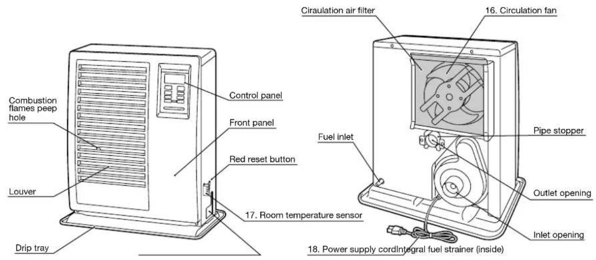
Your heater is equipped with a number of integral safety features. Please familiarize yourself with these features. If the heater shuts down due to the operation of any safety device, ensure the problem is identified and corrected. Note that normal combustion flames inside the combustion chamber, can be seen through a “peep hole”, located in the front bottom left hand corner of the hot air outlet louver’s.
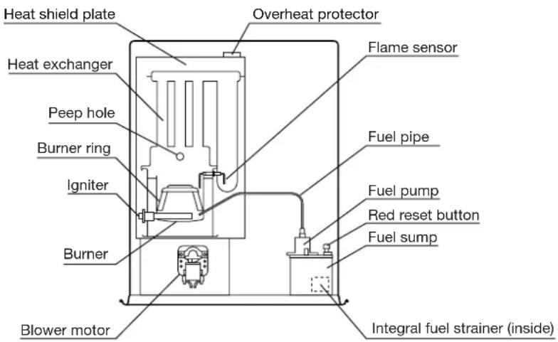
1. Flame Sensor
Heater will automatically stop all operations if ignition fails or if flame fails during combustion, in order to prevent fuel overflow. Error code will be displayed on the digital indicator.
2. Fuel Strainer
Special strainer catches any dirt or impurities present in the fuel before it is sent to the burner.
3. Overheat Protector
Automatically stops all operations if heater cabinet reaches abnormally high temperature due to motor malfunction or abnormal combustion, in order to prevent fire.
4. Power Failure Recovery System
If power fails during heater operation, heater will turn off. When power resumes, heater will automatically reignite and maintain the normal selected temperature.
NOTE: The operation varies depending on the time length of power failure and other conditions.
Please see page.14 for more details.
5. Fully Vented System
Flue pipe system provides outside air for combustion and vents all combustion products to the outdoors.
CAUTION: Heater and vent pipe system must be properly installed before operation. Please follow instructions under "Installation", Section I.

natural_image
Cartoon illustration of a smiling refrigerator with a pencil and sparkle effects (no text or symbols)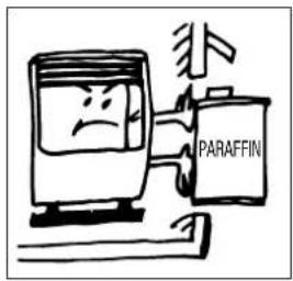
-
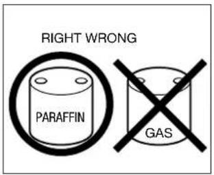
NEVER use any fuel other than Paraffin. NEVER USE GASOLINE. Use of gasoline can lead to uncontrollable flames, resulting in destructive fire.
-
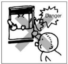
Due to high surface temperatures, keep heater away from children, furniture and clothing while in operation. (See Page 25.)
-
The appliance is not to be used by persons (including children) with reduced physical, sensory or mental capabilities, or lack of experience and knowledge, unless they have been give supervision or instruction.
• Children being supervised not to play with the appliance. - This appliance can be used by children aged from 8 years and above and persons with reduced physical, sensory or mental capabilities or lack of experience and knowledge if they have been given supervision or instruction concerning use of the appliance in a safe way and understand the hazards involved.
• Children shall not play with the appliance. -
Cleaning and user maintenance shall not be made by children without supervision.
-
To prevent abnormal operation and prolong heater life, be sure to perform routine maintenance. (See Page 15.)
-
NEVER store or transport fuel in other than a metal or plastic container that is acceptable for fuel and clearly marked "PARAFFIN". NEVER store fuel in the living space.
-
Operating Temperature Range Use heater within the range of temperatures indicated in the right figure.
Point A: If outside temperature -29°C than room temperature has to be -18°C or above
Point B: If outside temperature -43^ than room temperature has to be 16^ or above
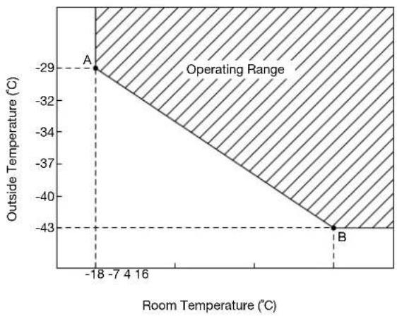
area
| Point | Room Temperature (°C) | Outside Temperature (°C) | |-------|------------------------|--------------------------| | A | -18 | -29 | | B | 0 | -43 |SECTION C: FUEL GUIDE
The FF V30 is designed for use with Paraffin. Use of low-quality fuel will cause burner performance to drop, leading to abnormal combustion and reduced heater life.
Purchase only Paraffin, in non-red cans reserved exclusively for fuel and marked accordingly with the word "PARAFFIN". Always store your fuel in a separate area from where you store gasoline for your power equipment to avoid accidental use of gasoline in your heater.
What to Buy ...
ALWAYS: Clean and high-quality Paraffin.
ALWAYS: Fuel free of contaminants, water or cloudiness.
NEVER: Gasoline, alcohol, white gas, camp stove fuel or additives.
NEVER: Yellow or sour-smelling fuel.
How to Store It...
ALWAYS: Store in a clean container, clearly marked PARAFFIN.
ALWAYS: Store away from direct sunlight, heat sources or extreme temperature changes.
NEVER: In a glass container, or one that has been used for other fuels.
NEVER: For longer than six months. Begin each heating season with fresh fuel; discard at the end of season.
NEVER: In the living space.
Why It is Important...
Pure, clean fuel is essential for safe and efficient heater operation. Poor quality or contaminated fuel can cause:
● Excess tar deposits on burner and flue pipe
- Incomplete combustion
- Reduced heater life
Use of a highly volatile flammable fuel such as gasoline can produce uncontrollable flames, creating a severe fire hazard.

SECTION D:
OPERATING CONTROLS AND PART NAMES
Before using heater, familiarize yourself with the following operating controls and part names.
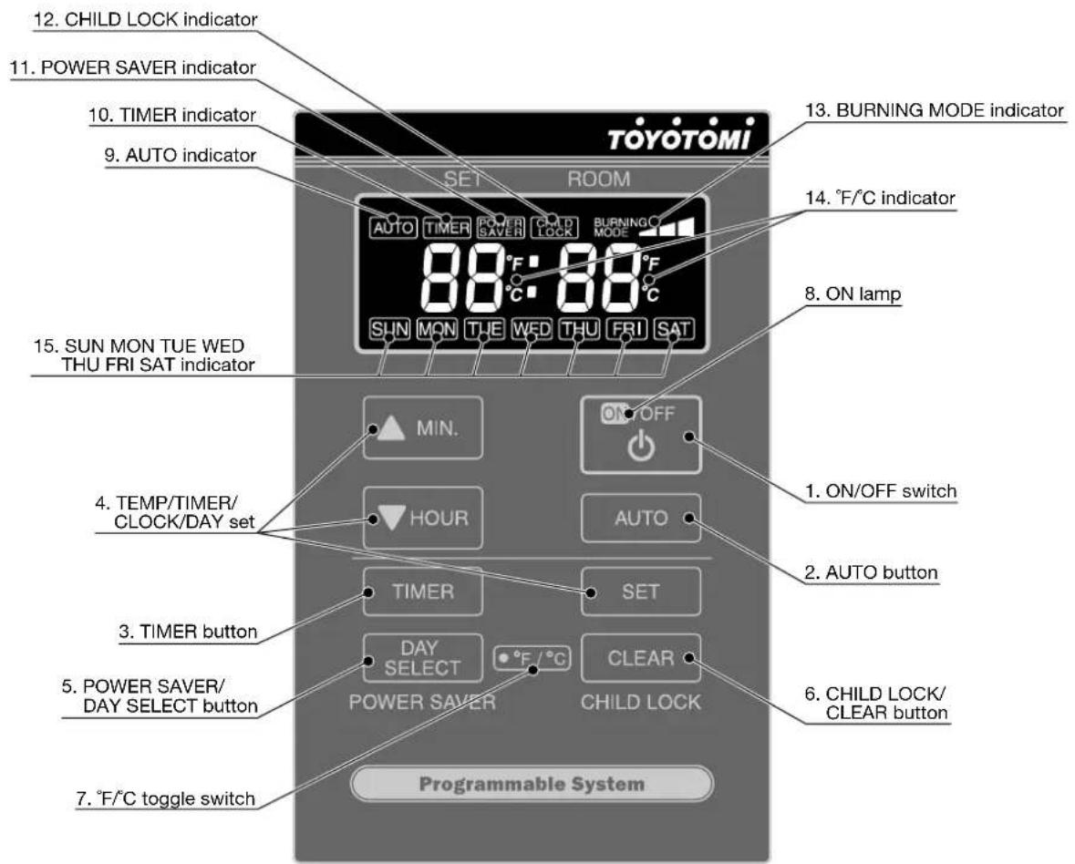
- ON/OFF switch:
- AUTO button:
- TIMER button:
- TEMP/TIMER/CLOCK/DAY set:
- POWER SAVER/DAY SELECT button:
- CHILD LOCK/CLEAR button:
- °F/°C switch:
- ON lamp:
- AUTO indicator:
- TIMER indicator:
- POWER SAVER indicator:
- CHILD LOCK indicator:
- BURNING MODE indicator:
- °F/°C indicator:
- SUN MON TUE WED THU FRI SAT indicator:
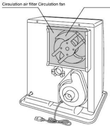
- Circulation fan:
- Room temperature sensor:
- Power supply cord:
Main switch turns heater on and off. When switched on, heater begins operation and combustion starts after preheat period.
The button turns weekly timer operation modes on and off which have been programmed into weekly timer.
The button turns weekly timer set mode on and off.
TEMP/TIMER/CLOCK/DAY set modes can be set by pressing the ▲/MIN. or ▼/HOUR buttons.
The button turns POWER SAVER operation mode on and off. When setting weekly timer, the button is used to select a day of the week.
The button turns CHILD LOCK operation mode on and off. When setting weekly timer, the CLEAR button is used.
°F/°C toggle switch.
Lit – Heater is in operation.
Flashing – Pre-heating and pre-purging.
Lit – Weekly timer operation is in use.
Lit – Heater operating in weekly timer set mode.
Lit – Heater operation in POWER SAVER mode.
Lit – Heater operation in CHILD LOCK mode.
Lit - Heater operation at high, medium or low combustion.
Lit – Digital indicator shows current temp.
Flashing – Current temp can be changed.
Lit – Digital indicator shows current day or timer day.
Three speed motor supplies high-capacity warm air flow during high combustion for heating room up quickly, and low or medium-capacity warm air flow during low or medium combustion for maintaining comfortable room temperature.
Constantly senses room temperature and supplies information to heater so that desired room temperature can be maintained.
The position of room temperature sensor can be changed by using the extension wire (*optional) (See Page 26.)
For use in 230V AC, 50Hz electrical outlet.
BEFORE IGNITION
1. Open the Valve(s)
Open the valve(s) of the external fuel tank.
2. Start the Fuel flow
If using heater for the first time, press the red reset button in order to send fuel to the fuel sump and release.
NOTE: Make sure there is no fuel leakage from the fuel line or joints. Also make sure fuel tank is not too high. See installation instructions.
3. Connect the Heater
Connect heater into a 230V AC, 50Hz electrical outlet. On digital indicator pre-set "Two Dashes" will be showing.
NOTE: Do not connect to an outlet shared with other appliances.
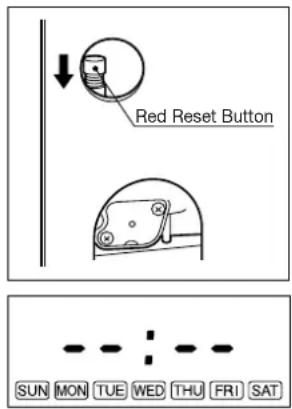
4. Set Clock
IMPORTANT: Clock on the heater must always be set to current time and day.
NOTE: The “▲MIN.” or “▼HOUR” button will change the time every one (1) unit. Holding the button continuously will cause the time to change rapidly.
NOTE: In the event of a power failure (more than approx. 30 min.), all clock and day may be cancelled.
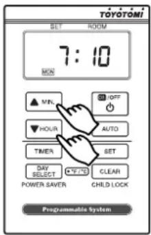
5. Setting of the Time and a day of the Week.
1) Current time is not set yet. (All signs light.)
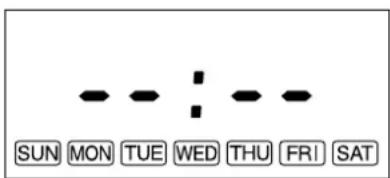
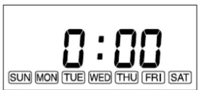
Press the “▲MIN.” button or “▼HOUR” button while in not operation. (Power switch is off.) 0:00 (midnight) is indicated on the display. (All signs except the colon are blinking.)
2) Setting of the current time
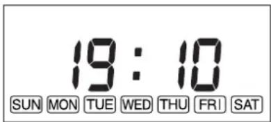
Press the “▲MIN.” button to set minutes and press the “▼HOUR” button to set hours.
When pressing the “▼HOUR” button, the sign will change as follows.
“0:00” → “1:00” → … → “11:00” → “12:00” → “13:00” → … “23:00” → “0:00” → …
When pressing the “▲MIN.” button, the sign will change as follows.
“0:00” → “0:01” → … → “0:59” → “0:00” → …
Press the "SET" button to complete the set of the current time.
3) Setting of a day of the week
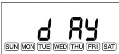
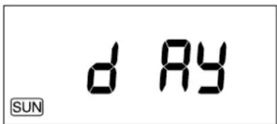
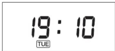
“dAy” sign is shown on the display and all of a day of the week blink.
Press the “▲MIN.” button or the “▼HOUR” button to set a day of the week. A day of the week will blink. (Initial setting is “SUN”).) The other days of the week will go off. Select a day of the week by using the “▲MIN.” or the “▼HOUR” button. When pressing the “▲MIN.” button, the sign will change as follows.
“SUN” → “MON” → “TUE” → “WED” → “THU” → “FRI” → “SAT”
When pressing the “▲MIN.” button at the position of “SAT”, you can hear the beep sound and “SAT” is not changed any more. When pressing the “▼HOUR” button, the sign will change as follows.
“SAT” → “FRI” → “THU” → “WED” → “TUE” → “MON” → “SUN”
When pressing the “▼HOUR” button at the position of “SUN”, you can hear the beep sound and “SUN” is not changed any more.
Press the “SET” button to complete the set of a day of the week. The current time and a day of the week will show on the display.
NOTE: If the ON/OFF switch is pressed during resetting of the current time and a day of the week after setting the time and a day of the week, the set mode of the current time will terminate and the operation will start. If a day of the week is set, the time is fixed at the resetting time. If a day of the week is not set, the contents of the setting are deleted.
OPERATION
MANUAL OPERATION
Operation of the heater is under the direct control of the user. Heat output will, however, be automatically adjusted in accordance with the room temperature registered by the temperature sensor.
1. Turning Heater ON
A. Press ON/OFF switch to "ON" position. The current room temperature and the set temperature will be shown on the digital indicator. ON lamp will start to flash and then blower motor and ignition will start. This lamp will continue to flash during the preheating time.
B. After approx. 1.5 – 4 minutes ignition will take place. (*) After ignition, ON lamp will change flashing to continuous. Circulation fan will turn on after approx. 2 minutes.
NOTE: (*) Pre -heating depends on the room temperature.
Room temperature:
under 0°C 4 minutes
0°C - 15°C 2 minutes
15°C 1.5 minutes
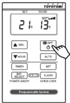
2. Adjusting Room Temperature
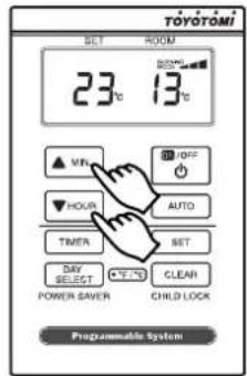
A. Press the "▲MIN." or "▼HOUR" button. °F or °C will start to flash.
NOTE: The "▲MIN." or "▼HOUR" button will change the temperature in increment of 1°C (2°F).
B. Press the “▲MIN.” or “▼HOUR” button as required. Room temperature can be set from 10°C (50°F) to 32°C (90°F). (Initial setting : 13°C (56°F))
NOTE: Desired temperature setting will be displayed on the digital indicator when you set the room temperature.
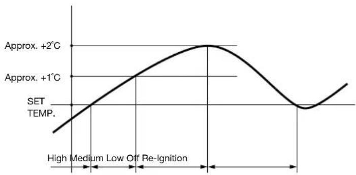
C. When room temperature reaches the selected setting, heater will automatically shift to "MED" or "LOW" burning mode to maintain the desired temperature.
When room temperature exceeds the selected setting by approx. 2^ C ( 4^ F), the heater will automatically shut off. As room temperature drops, the heater will automatically re-start to maintain the desired temperature.
line
| Time Interval | Temperature | | ------------- | ----------- | | Low | Approx. +1°C | | High | Approx. +2°C | | Off Re-Ignition | Approx. +1°C |The Power Saver mode reduces the frequency of ignition actions, to save electric consumption.
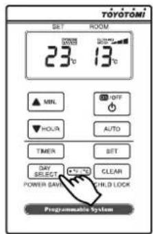
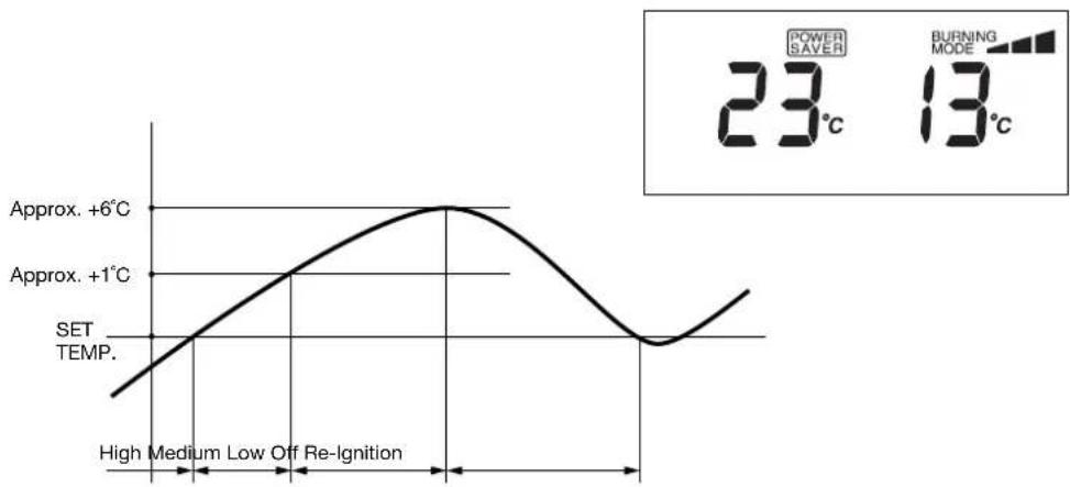
Press the POWER SAVER (DAY SELECT) button "ON" while in operation to start the operation of the "POWER SAVER". "POWER SAVER" sign will be shown on the digital indicator.
When the room temperature exceeds the selected setting by approximately 6^ C ( 10^ F), the heater will automatically shut off. As the room temperature becomes lower than the selected setting, the heater will automatically re-start to maintain the desired temperature.
line
| Condition | Value | | ----------------- | --------- | | Approx. +6°C | Approx. +6°C | | Approx. +1°C | Approx. +1°C | | SET TEMP. | SET TEMP. | | High | Low | | Medium | Low | | Off | Off | | Re-Ignition | Re-Ignition | | Power Saver | 23°C | | Burning Mode | 13°C |Press the CHILD LOCK (CLEAR) button for more than 3 seconds to set the childproof lock while in operation or not operation. "CHILD LOCK" sign will be shown on the digital indicator.
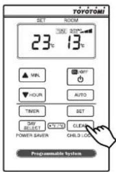
The childproof lock can be used to prevent children accidentally changing the heater settings. When the heater is burning and the childproof lock is on, the heater can only be switched off. Other functions are blocked then. If the heater has already been switched off, the childproof lock also prevents accidental ignition of the heater.
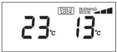
To release the child lock operation, press the CHILD LOCK (CLEAR) button for more than 3 seconds.
NOTE: If special notice does not state, when pressing button, you can hear the beep sound.
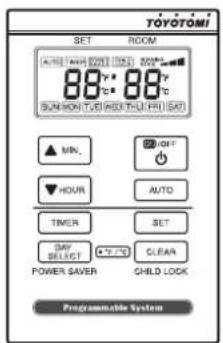
1. Set the Weekly Timer
NOTE: The following programs are set at the factory in advance.
| Program # | Clock Time | Temp. | Day |
| P01 | 6:00 | 20°C (68°F) | “MON” “TUE” “WED” “THU” “FRI” |
| P02 | 8:30 | 16°C (62°F) | “MON” “TUE” “WED” “THU” “FRI” |
| P03 | 17:00 | 20°C (68°F) | “MON” “TUE” “WED” “THU” “FRI” |
| P04 | 23:00 | 16°C (62°F) | “MON” “TUE” “WED” “THU” “FRI” |
| P05 | 7:00 | 20°C (68°F) | “SUN” “SAT” |
| P06 | 10:00 | 16°C (62°F) | “SUN” “SAT” |
| P07 | 16:00 | 20°C (68°F) | “SUN” “SAT” |
| P08 | 23:00 | 16°C (62°F) | “SUN” “SAT” |
After setting the current time and a day of the week, press the “TIMER” button to enter the weekly timer setting mode. The “TIMER” is shown on the display. When the “TIMER” button is pressed during setting of the weekly timer, the “TIMER” sign is disappeared and the current clock time and a day of the week are shown on the display.
NOTE: You cannot enter the weekly timer setting mode, while in operation at AUTO operation mode.
1) Select the program number
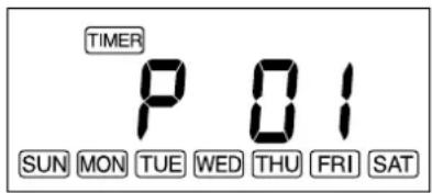
Press the “▲MIN.” button or the “▼HOUR” button to select the program number.
The number of the program is 30. The unsetting program number is flashing on the display. In the case of the first setting of the weekly timer, "P01" is shown on the display and will blink. When the unsetting program number is shown on the display, all of a day of the week will also blink.
When pressing the “▲MIN.” button, the sign will change as follows.
$$ " P 0 1" \rightarrow " P 0 2" \rightarrow \dots \rightarrow " P 2 9" \rightarrow " P 3 0" $$
When pressing the “▲MIN.” button at the position of “P30”, you can hear the beep sound and “P30” is not changed any more.
When pressing the “▼HOUR” button, the sign will change as follows.
$$ " \mathrm{P} 3 0" \rightarrow " \mathrm{P} 2 9" \rightarrow \dots \rightarrow " \mathrm{P} 0 2" \rightarrow " \mathrm{P} 0 1" $$
When pressig the “▼HOUR” button at the position of “P01”, you can hear the beep sound and “P01” is not changed any more.
Basically, the only next program number of the biggest set program number is shown on the display and blinks.
All of 30 programs will not be shown on the display.
In case that the program is already set, the next number of the biggest setting program number is shown on the display. If the program is set until "P30", "P30" is shown on the display and will blink. Even though the program is set until "P30", if there is the unsetting program number, the smallest unsetting program number is shown on the display.
Example:
In case that "P01" and "P02" programs are set and "P03" is not set, the display is indicated as follows.
“P01” – lighting “P02” – lighting “P03” – flashing 3
In case that “P01” and “P04” programs are set and “P02” and “P03” are not set, the display is indicated as follows.
“P01” – lighting “P02” – flashing 3 “P03” – flashing 3 “P04” – lighting “P05” – flashing 3
Press the "SET" button to move to the next step (Set the timer).
The program number is eliminated by holding the "CLEAR" button continuously for 3 seconds.
2) Set the timer
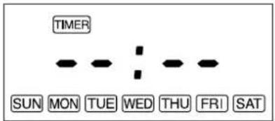
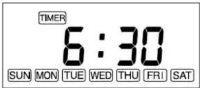
The timer time is shown on the display. (In case that the timer time is not set, the bars are shown on the display.) Press the “▲MIN.” button or the “▼HOUR” button to set timer time. “0:00” will be shown on the display. (The all signs except the colon will blink.)
When pressing the "▼HOUR" button, the sign will change as follows.
$$ " 0: 0 0" \rightarrow " 1: 0 0" \rightarrow \dots \rightarrow " 1 1: 0 0" \rightarrow " 1 2: 0 0" \rightarrow " 1 3: 0 0" \rightarrow \dots \rightarrow " 2 3: 0 0" \rightarrow 0: 0 0" \rightarrow \dots $$
When pressing the “▲MIN.” button, the sign will change as follows.
$$ " 0: 0 0" \rightarrow " 0: 1 0" \rightarrow " 0: 2 0" \rightarrow " 0: 3 0" \rightarrow " 0: 4 0" \rightarrow " 0: 5 0" \rightarrow " 0: 0 0" \rightarrow \dots $$
Press the "SET" button to complete the set of the timer time and to move to the next step (Set the temperature of the program).
In case that the "SET" button is pressed when showing the bars sign on the display, you can hear the beep sound and cannot move to the next step.
3) Set the temperature of the program
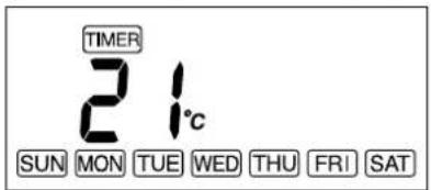
The set temperature "21" will be shown on the display and it will blink.
Press the “▲MIN.” button or the “▼HOUR” button to set the temperature of the program. The “▲MIN.” button or the “▼HOUR” button will change temperature every 1°C (2°F).
Press the "SET" button to complete the set the temperature of the program and move to the next step (Set a day of the week of the program).
4) Set a day of the week of the program
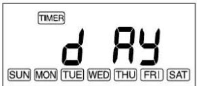
The “dAy” sign will be shown on the display and the “SUN” will blink. Press the “▲MIN.” button or the “▼HOUR” button to set a day of the week of the program. When pressing the “▲MIN.” button, the program is set at the day of the week. The day of the week will light. When pressing the “▼HOUR” button, the set day of the week is reset. The day of the week will go off. At this time, the sign is moved to the next day of the week automatically. When pressing the “DAY SELECT” button, the display will be shown the next day of the week without setting. The sign of a day of the week will change as follows.
$$ " \text { SUN }" \rightarrow " \text { MON }" \rightarrow " \text { TUE }" \rightarrow " \text { WED }" \rightarrow " \text { THU }" \rightarrow " \text { FRI }" \rightarrow " \text { SAT }" \rightarrow " \text { SUN }" \rightarrow \dots $$
Press the "SET" button to complete the set of a day of the week of the program and it will go back to the select of the program number. In case that a day of the week is not set, when pressing the "SET" button, yo can hear the beep sound and cannot move to the next step.
2. Activate Weekly Timer Operation
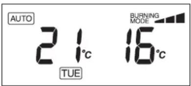
During operation (in a SW/ON position), press the “AUTO” button to enter the weekly timer operation mode. The “AUTO” sign will be shown on the display. However, if no program is set, you can hear the beep sound and cannot enter the weekly timer operation mode. Press the “▲MIN.” button or the “▼HOUR” button to change the set temperature. However, if the next program starts, the temperature will be changed to the temperature of the next program.
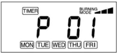
During operation, press the "TIMER" button to enter the weekly timer set mode (Select of the program number). If the "TIMER" button is pressed during the setting of the weekly timer set mode, the weekly timer set mode is released. Change of setting is applied as soon as the AUTO operation starts.
MANUAL COMBUSTION
IMPORTANT: This feature is for testing purpose only!
This heater also can be kept burning at desired combustion mode (High, Medium or low) manually, regardless of room temperature.
- Press the “▲MIN.” button and “▼HOUR” button at the same time for more than three (3) seconds when ON / OFF switch is “ON”.
- P1, P2 or P3 will be displayed on the Digital indicator;
$$ P 1 = \text { Low mode } $$
$$ P 2 = \text { Medium mode } $$
$$ P 3 = \text { High mode } $$
Then select desired combustion mode by pressing “▲MIN.” or “▼HOUR” button. “▲MIN.” button changes combustion mode to higher, “▼HOUR” button changes combustion mode to lower.
- To clear, press the “▲MIN.” button and “▼HOUR” button at the same time for more than (3) seconds until normal temperature display returns.
AUTOMATIC CLEANING MODE
When the heater has been burning continuously for two hours at its highest setting, the burner will automatically start an auto clean procedure. The display will show the auto cleaning code cl:05 running back to cl:01. The procedure takes 5 minutes to clean the burner automatically while the heater will burn at its lowest setting. When the burner is clean again, the heater will automatically switch back to the highest setting again.
If at any time a power failure occurs during operation, heater will turn off. When the power returns, the unit will automatically restart with the following conditions. Please reset each setting when the settings are erased as indicated below.
| TIME LENGTH OF POWER FAILURE | LESS THAN 3 SECONDS | MORE THAN 3 SECONDS | |
| IN BACKUP MEMORY | OUT OF BACKUP MEMORY | ||
| OPERATION | Restart the combustion with the same condition before the power failure. | Start the combustion from the beginning. | Start the combustion from the beginning.Set temperature will change to 13°C (56°F) for safety.Set temperature and room temperature will blank that at least more than 30 min. power failure has occurred.To stop the blinking the set temperature and room temperature, press any button once. |
| POWER SAVER OPERATION | Keep the same condition before the power failure. | Keep the same condition before the power failure. | Keep the same condition before the power failure. |
| AUTO OPERATION | Keep the same condition before the power failure. | Keep the same condition before the power failure. | The setting will be erased.(See Page 13.) |
| CHILD LOCK OPERATION | Keep the same condition before the power failure. | The setting will be erased.(See Page 10.) | The setting will be erased.(See Page 10.) |
If at any time a power failure occurs when heater is not in operation, the unit will basically start the operation while keeping the same condition before the power failure. However, when the power failure continued more than 3 seconds, the following settings will be erased. Please reset each setting.
WHEN HEATER IS NOT IN OPERATION
| IN BACKUP MEMORY | Child lock operation (See Page 10.) |
| OUT OF BACKUP MEMORY | Clock and Day setting (See Page 7.) |
| Auto operation (See Page 13.) | |
| Child lock operation (See Page 10.) |
TURNING HEATER OFF
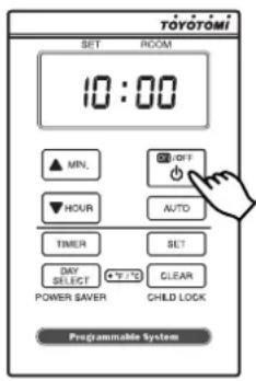
Press ON/OFF switch to "OFF" position. ON lamp will flash and will go out. Circulation fan and blower motor continue to run for approx. three (3) minutes to cool down the heater. Make sure ON lamp goes out when the fan stops.
SECTION F: ROUTINE MAINTENANCE
CAUTION: Be sure to disconnect heater before performing any checks or cleaning.
CAUTION: Allow heater to cool completely before cleaning or maintenance.
FOR OPTIMUM HEATER PERFORMANCE, THE PARTS SHOWN BELOW SHOULD BE CLEANED REGULARLY:
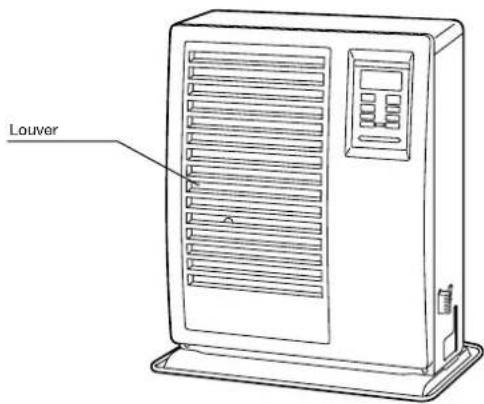
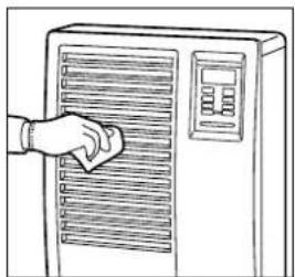
1. Clean Louvers (ONCE A WEEK)
Dust and stains should be wiped off louvers with a damp cloth.
natural_image
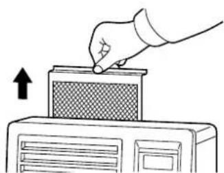
Line drawing of a hand pressing down on a front panel of a refrigerant appliance (no text or symbols)2. Clean Circulation Air Filter (ONCE A WEEK)
A mesh filter is located on heater cabinet rear side. Once a week slide the filter up to remove and it should be vacuumed clean.
natural_image
Illustration of a hand inserting a component into a computer tower (no text or symbols)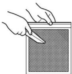
natural_image
Illustration of hands holding a tool over a textured surface (no text or symbols)3. Check for Fuel Leaks (REGULARLY)
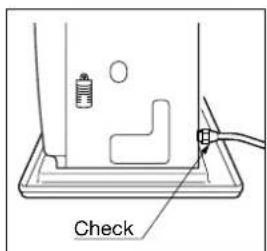
Make it a habit to check for any sign of fuel leakage along the fuel line and at all joints. Fuel leaks may lead to risk of fire.
4. Check Flue Pipe Area (ONCE A WEEK)
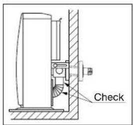
Check the flue pipe joint to make sure connection is firm. Use a vacuum cleaner to remove any dust or pet hair.
5. Clean Fuel Strainer (ONCE A MONTH)
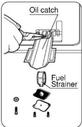
The strainer of the fuel sump should be cleaned once a month and before storing heater at the end of each season.
(a) Close the valve(s) of the separate fuel tank.
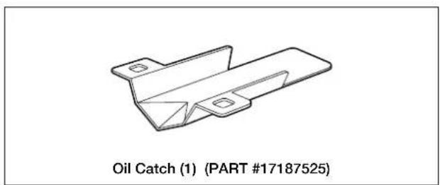
(b) To catch the fuel which will drain out, set the oil catch below the strainer cover, with a small container under it.
(c) Loosen the two screws from the strainer cover and remove.
(d) Remove the strainer and wash with fuel.
(e) Return the strainer to its original position. Replace strainer cover and screw to secure.
(f) Wipe away any spilled fuel.
(g) Open the valve(s) of separate fuel tank. Check for fuel leakage.
NOTE: Be sure to unscrew the drain screw to remove all remaining fuel from the fuel sump at the end of each season.
6. Recommended Periodic Maintenance
As a state-of-the-art furnace, your heater requires periodic inspection and service by an authorized technician to insure optimum, trouble free performance. This inspection should include: a combustion check; flue pipe check; burner assembly check; cleaning all necessary parts and replacing gaskets as needed. Please ask your authorized TOYOTOMI dealer for details and scheduling.
AUTOMATIC IGNITER CLEANING SYSTEM
The igniter cleaning mode prolongs the igniter life.
When the heater is on and clock is set (See “Set Clock” on page 7), it will automatically stop and clean the igniter every day at 2:00 and will display “CL” on the digital indicator. After the cleaning mode is finished the heater will automatically re-ignite and continue to burn again.
MANUAL IGNITER CLEANING SYSTEM
Heater will clean igniter for ten (10) minutes manually.
- When ON/OFF switch is "OFF", press the "SET" button and "CLEAR" button at the same time for more than three (3) seconds.
- Display will appear "CL:10" on Digital indicator. Cleaning will begin and end without any additional input.
NOTE: Cleaning igniter is important to prolong igniter life. It is recommended that the igniter be cleaned once a week.
BEFORE REQUESTING A SERVICE CALL
The following symptoms are normal during operation of the heater.
| CONDITION | REASON | |
| When heater is started or extinguished. | White smoke or smell inside home when the heater is first used. | Machine oil used in factory assembly, or transit dust burns off the surfaces of the burner or heat exchanger. |
| Flashing flames visible in viewing window for a few minutes after ignition. | The burner is cold and igniter is kept running for a while after. | |
| Irregular metallic “cracking” noises when heater is ignited or extinguished. | Expansion / contraction of hot metal components within the heater warming and cooling. | |
| Warm air is not discharged as soon as ignited. | Delay is to prevent nuisance cool air. | |
| Audible “chugging sound” from fuel pump. | Air is in the fuel pump (No fuel). At first “Start Up” the rapid “chugging noise”, may continue for a minute or two, until air is purged from the pump*. | |
| When heater is in operation. | Regular pulse “Ticking” noise from heater. | Sound of fuel pump in normal operation. |
| Heat chamber or heat exchanger can be seen through the air outlet louver’s glowing red hot. | Normal | |
| Occasional yellow flickering in blue flame. | Normal |
*If rapid “chugging” sound from fuel pump does not cease and if heater shuts OFF......
- Push Fuel Sump Red Reset Button. (See Page 7.) DO NOT hold down.
- Insure that all valves (including fire valve) are open.
- Insure external fuel tank has fuel and fuel filters are clean.
| ERROR CODE | INFORMATION | WHAT TO DO |
| E-0 | Power failure (low voltage, unstable frequency) | Check power source. |
| E-2 | Ignition safety feature is activated. / No fuel | Contact your dealer. / Refill fuel. |
| E-6 | Extinguished during operation. / No fuel | Contact your dealer. / Refill fuel. |
| E-8 | Blower motor malfunction | Contact your dealer. |
| E-12 | Overheating safety feature is activated. | Clean the air filter and remove dust. |
| E-13 | Burner thermistor malfunction | Contact your dealer. |
| Excess fuel in the burner | Contact your dealer. | |
| E-22 | Ignition failure three times | Contact your dealer. |
| E-23 | Primary flame rod (Flame sensor) is malfunction and/or dirty | Consult your dealer. |
| -- : -- | Timer is not setting. | Set the timer. |
| Hi | Room temperature is higher than 35°C (95°F). Position of room temperature sensor is not correct. | Check the position of room temperature sensor. / Contact your dealer. |
| Lo | Room temperature is lower than -10°C (14°F). Room thermistor malfunction or disconnected. | Check the position of room temperature sensor. / Contact your dealer. |
At the close of each heating season, or when you do not plan to use your heater for an extended period, the following procedures are recommended.
-
As the end of the season approaches, calculate your fuel purchases so that you can use up all the fuel you have on hand. When fuel is stored for over six months, its quality may deteriorate. The use of such fuel will have an unfavorable effect on heater operation.
-
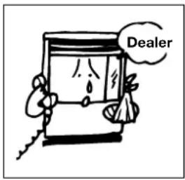
If your heater needs any service or repair, now is the time to call your dealer and get it done before storage. That way your heater will be ready for immediate use when the next heating season begins.
-
If you plan to store your heater in place,
(a) Disconnect power supply.
(b) Close the main tank valve.
(c) Remove all fuel from the fuel sump and clean the fuel strainer. (See Page 16.)
(d) Wipe off any stains or dust on heater with a damp cloth, then wipe once again using a dry cloth.
(e) Cover heater completely with a large plastic bag to protect from dust.

natural_image
Cartoon illustration of a smiling computer with a brush and stars (no text or symbols)- To store heater in another location,
(a) Disconnect heater.
(b) Close the main tank valve.
(c) Remove all fuel from the fuel sump and clean the fuel strainer.
(d) Disconnect fuel line and flue pipe from the heater.
NOTE: Fuel remaining in the fuel line may flow out when fuel line is disconnected. Have a container ready to catch drainage.
(e) Remove any soot accumulated in the flue pipe using a brush and/or vacuum cleaner.
(f) Wipe off any stains or dust on heater with a damp cloth, then wipe once again using a dry cloth.
(g) Put the heater in the original shipping box, and store in a dry place. If original shipping box is not available, cover the heater completely with a large plastic bag to protect from dust during storage.
(h) Cover exhaust and air intake openings of the flue pipe by using optional caps.
(Part #17212661 and #17212656)
TRANSPORTATION
Take the following measures to avoid fuel leakage during the transportation of the heater.
- ALWAYS move the heater in an upright position.
- ALWAYS drain fuel from the fuel sump before transportation.
SECTION I: INSTALLATION
GENERAL DESCRIPTION: The FF V30 is designed to be installed in an outside wall so the full advantage of installation simplicity can be made with the "Flue Pipe", which eliminates the need for tall chimney type flues. No hearth or fire surround is required. While some Flue pipe wall extensions are available, they complicate installation. Read and understand the limitations of Flue pipe wall extension options.
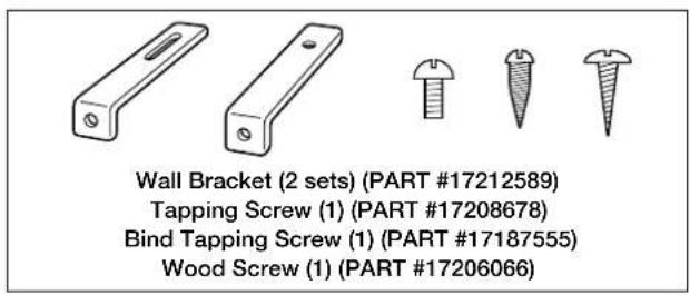
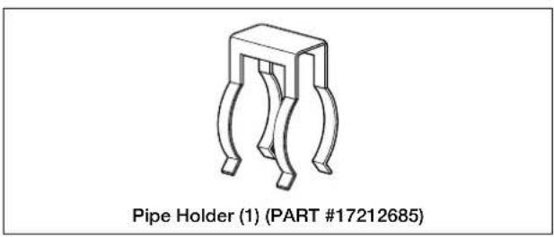
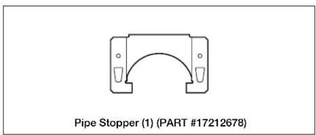
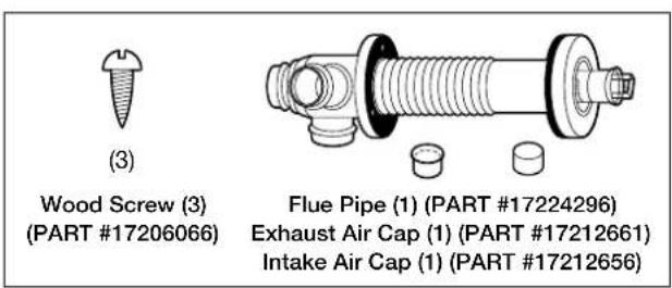
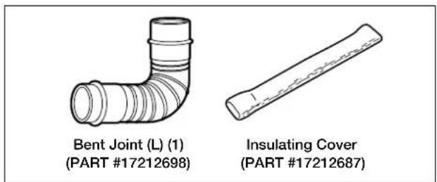
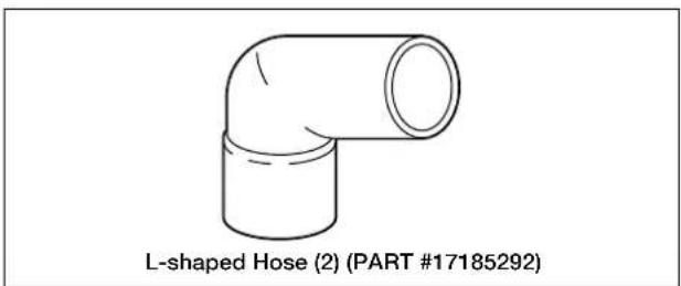
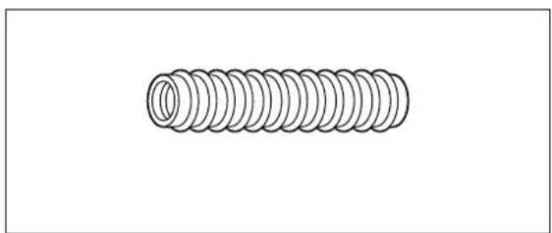
STANDARD INSTALLATION PARTS
The following standard installation parts are enclosed with heater. For alternate installation methods, you may need
natural_image
Simple line drawing of a coiled spring (no text or symbols)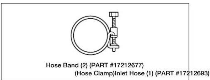
INSTALLATION ADVICE
-
Intake air and exhaust flue pipe openings of the Flue Pipe must be fully exposed to outside. The Flue Pipe must not vent into a chimney, garage, basement, under-floor or ceiling cavity, or any enclosed area, or be installed vertically, because the Flue Pipe is a "Heat Exchanger" which causes condensate to form in the exhaust pipe, and which must drain to outside. (See Fig. 2 Page 25).
-
Install Flue Pipe (See Fig. 2 and 3, Page 25.) Note the volume and temperature of the hot exhaust gas that the exhaust pipe discharges to outside, is minimal, and does not normally present any problems.
-
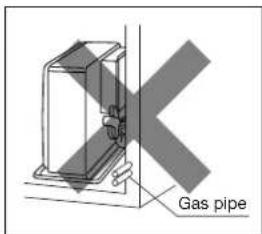
Before making a hole in the wall for the Flue Pipe ensure the wall cavity is free of electrical wires, gas pipes and other obstacles. Drilling a 5 mm "pilot hole" from inside enables the final hole (and any associated "mess") to be completed from outside.
-
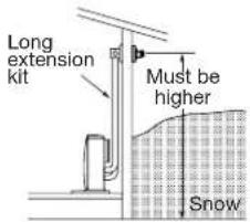
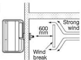
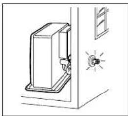
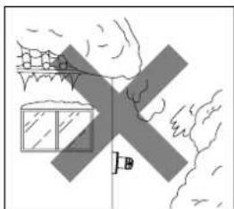
DO NOT install Flue Pipe where the air supply or exhaust gas outlet might become covered by snowdrifts, fouled by outdoor debris, or directly exposed to winds over 50 kph.
IMPORTANT:
In areas of heavy snow falls, ground surface clearance must be increased according to average snow falls.
IMPORTANT:
In open area with strong wind, a wind break may be necessary.
natural_image
Simple line drawing of a door with a switch and lamp (no text or symbols)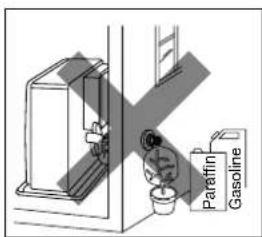
natural_image
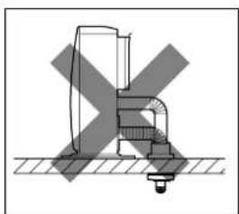
Simple line drawing of a house with a cross symbol, no text or symbols present- NEVER install the Flue Pipe below the heater.
natural_image
Pure mechanical assembly diagram without any text, numbers, or symbols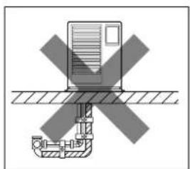
natural_image
Pure diagram of a mechanical or electrical component with cross-hatching, no text or symbols present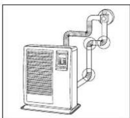
natural_image
Line drawing of a refrigerant air conditioning unit with coiled pipes and ventilation slots (no text or symbols)- Total length of any Extension Pipe Kits (accessories L, M or S) between heater and Flue Pipe must not exceed 3 m, with not more than 3 × 90^ bends.
NOTE: When using Extension Pipe Kits type L, M or S always insulate hot exhaust pipe with the insulating cloth cover supplied. (More insulation may be required by Local Authority).
- For all heater installations, the Flue Pipe must always be installed. It must be horizontal with slight fall to outside ... NEVER vertically.
INSTALLATION OF HEATER AND FLUE PIPE
A) Before commencing any installation work, check that the proposed installation will comply with Building Code requirements and Local Consent Authority rules that may apply to vented heaters in your area. (Check your Local Authority website, or consult your Installer / Supplier.)
B) The Flue Pipe is designed to be installed through the wall of any conventional building cladding, including Brick, Hebel, Linear, Gibraltar and Plaster Board, Tiles, Weatherboard, Plastered Polystyrene, and metal profiles etc.
C) The FF V30 heater is designed to be operated at altitudes up to 900 m, above sea level. For installation at altitudes between 900 m and 1800 m, adjustments by authorized serviceperson is necessary. Consult your supplier for advice.
1 Select heater location. Ensure minimum clearances as indicated below between heater and nearest combustible materials. (See Fig. 1.) Provide service access to clean the circulation air filter, integral fuel strainer and reset button.
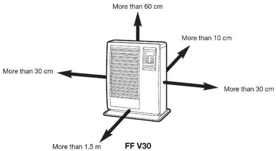
Fig. 1
- Ensure the outdoor flue discharge area is clear of anything that might be affected by the hot flue exhaust gas. (See Fig. 2 and 3.)
The Flue Pipe (as in Fig. 2), is for wall thickness from 130 mm to 320 mm.
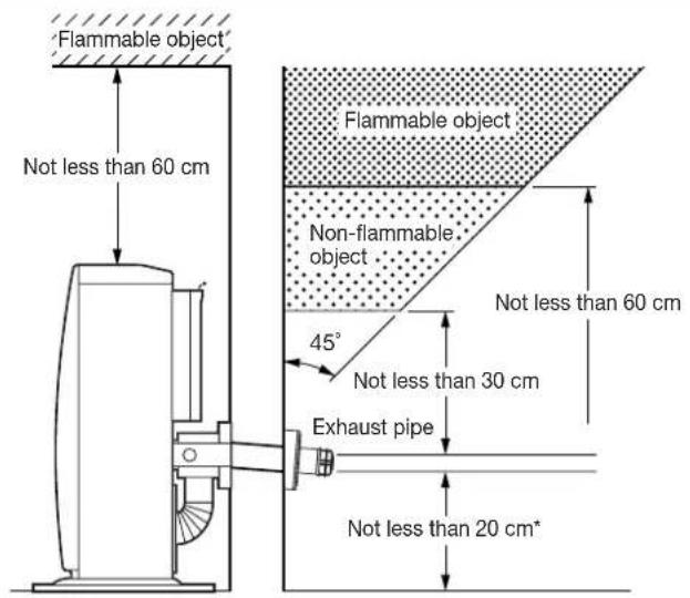
Fig. 2 Fig. 3
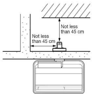
Flue Pipe Installation
EXTENSION WIRE OF ROOM TEMPERATURE SENSOR
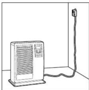
A room temperature sensor is located on the right side of the cabinet in front. The room temperature sensor is installed in the sensor case. When the room temperature cannot be reached at the desired temperature depending on the installation situation, the extension wire (*optional) is available to change the location. Please refer to the following procedure.
- Unfasten a screw to disassemble the sensor case on the cabinet with a driver.
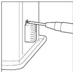
natural_image
Technical line drawing of a mechanical assembly with a tool inserted into a component (no text or symbols)- Remove the connector by holding with fingers and attach the extension wire.
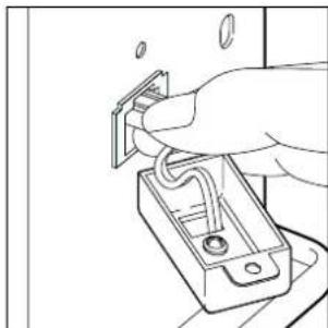
natural_image
Line drawing of a hand inserting a small component into a battery (no text or symbols)- Attach the extension wire to the connector on the side of the room temperature sensor.
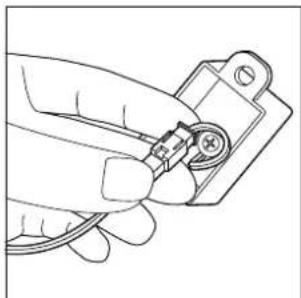
natural_image
Hand holding a small electronic component with wires, no visible text or symbols- Install the sensor case to the location where the room temperature can be reached at the desired temperature.
natural_image
Line drawing of a portable air conditioner unit connected to a wall-mounted cable (no text or symbols)TOYOTOMI CO., LTD.
5-17, Momozono-cho, Mizuho-ku, Nagoya, Japan
- IMPORTANT
- CONTENTS
- SAFETY FEATURES
- Flame Sensor
- Fuel Strainer
- Overheat Protector
- Power Failure Recovery System
- Fully Vented System
- SECTION C: FUEL GUIDE
- SECTION D:
- OPERATING CONTROLS AND PART NAMES
- BEFORE IGNITION
- Open the Valve(s)
- Start the Fuel flow
- Connect the Heater
- Set Clock
- Setting of the Time and a day of the Week.
- 3) Setting of a day of the week
- OPERATION
- MANUAL OPERATION
- Turning Heater ON
- Adjusting Room Temperature
- Set the Weekly Timer
- 1) Select the program number
- Example:
- 2) Set the timer
- 3) Set the temperature of the program
- 4) Set a day of the week of the program
- Activate Weekly Timer Operation
- MANUAL COMBUSTION
- AUTOMATIC CLEANING MODE
- TURNING HEATER OFF
- SECTION F: ROUTINE MAINTENANCE
- Clean Louvers (ONCE A WEEK)
- Clean Circulation Air Filter (ONCE A WEEK)
- Check for Fuel Leaks (REGULARLY)
- Check Flue Pipe Area (ONCE A WEEK)
- Clean Fuel Strainer (ONCE A MONTH)
- Recommended Periodic Maintenance
- AUTOMATIC IGNITER CLEANING SYSTEM
- MANUAL IGNITER CLEANING SYSTEM
- BEFORE REQUESTING A SERVICE CALL
- TRANSPORTATION
- SECTION I: INSTALLATION
- STANDARD INSTALLATION PARTS
- INSTALLATION ADVICE
- IMPORTANT:
- INSTALLATION OF HEATER AND FLUE PIPE
- EXTENSION WIRE OF ROOM TEMPERATURE SENSOR
- TOYOTOMI CO., LTD.
Brand : Toyotomi
Model : FF V30 (Type B)
Category : Heating