
LRP-104CET - Wi-Fi repeater Planet - Free user manual and instructions
Find the device manual for free LRP-104CET Planet in PDF.


| Product Type | Industrial 1-Port Coax/UTP Long Reach PoE+ 4-Port 10/100TX PoE Extender |
| Brand | Planet |
| Model | LRP-104CET |
| Dimensions (W x D x H) | 135 x 87.8 x 56 mm |
| Weight | 644 g |
| Enclosure Material | Aluminum metal case |
| Power Input | 44-56V DC over coaxial or 24-48V DC via terminal block (redundant) |
| Power Consumption | 130 watts (full PoE load) |
| PoE Standard | IEEE 802.3at/af, End-span, 52V DC output |
| PoE Power Budget | Up to 120W with external DC supply; per port up to 25W |
| Copper Ports | 4 x 10/100BASE-TX RJ45 with auto-MDI/MDI-X |
| Long Reach Ports | 1 x BNC female (coaxial) and 1 x RJ45 (UTP) |
| Maximum Distance (Coaxial) | 200m with PoE+, 400m with PoE, 1000m without PoE |
| Maximum Distance (UTP) | 100m with PoE+, 400m with PoE |
| Data Rate | Up to 91/88 Mbps (200m coaxial), up to 90/87 Mbps (100m UTP) |
| LED Indicators | 2 for power (P1, P2), 1 fault (red), 4 for PoE usage (10W-40W), 2 for LRP (PWR, LNK), per RJ45: LNK/ACT (green), PoE-in-use (orange) |
| DIP Switches | 4 switches to enable/disable PoE per port |
| Installation | DIN rail kit and wall-mount kit included |
| Operating Temperature | -20 to 70°C |
| Humidity | 5% to 95% (non-condensing) |
| Regulatory Compliance | FCC Part 15 Class A, CE |
| Alarm Contact | 1 relay output for power failure, 1A @ 24V DC |
| Compatibility | Planet LRP-101CH, LRP-101UH, LRP-822CS, LRP-1622CS |
Frequently Asked Questions - LRP-104CET Planet
User questions about LRP-104CET Planet
0 question about this device. Answer the ones you know or ask your own.
Ask a new question about this device
Download the instructions for your Wi-Fi repeater in PDF format for free! Find your manual LRP-104CET - Planet and take your electronic device back in hand. On this page are published all the documents necessary for the use of your device. LRP-104CET by Planet.
USER MANUAL LRP-104CET Planet
Industrial 1-Port Coax/UTP Long Reach PoE+ 4-Port
10/100TX PoE Extender
LRP-104CET
User's Manual
Table of Contents
- Package Contents.... 3
- Application Diagram.... 4
2.1 Point to Multi-point 4
2.1.1 LRP-101CH to LRP-104CET 4
2.1.2 LRP-101UH to LRP-104CET 5
2.2 Multi-Point to Multi-Point 6
2.2.1 LRP-822CS/LRP-1622CS to LRP-104CET 6
- Hardware Introduction ...... 7
3.1 Physical Dimensions....7
3.2 Front Panel 8
3.3 The Upper Panel 8
3.4 LED Indicators....9
3.5 PoE DIP Switch Indication....10
- Hardware Specifications ....11
- Installation Precautions....15
5.1 Installation Precautions of Remote Power by Coaxial Cable....15
5.2. Installation Precautions of Remote Power by UTP Cable....15
5.3 Installation Precautions of Local Power 16
5.4 Wiring the Fault Alarm Contact ....17
- Installation ....18
6.1 Applications of LRP-101CH or LRP Switch with coaxial cable .....18
6.2 Applications of LRP-101U-KIT with UTP/Twisted-pair Cable .....21
6.3 Applications of LRP Injector or LRP Switch powered by External DC power supply....24
Appendix A: Networking Connection....27
A.1 Switch's RJ45 Pin Assignments....27
A.2 RJ45 Cable Pin Assignments 27
1. Package Contents
Thank you for purchasing PLANET Industrial 1-Port Long Reach PoE+4-Port 10/100TX PoE Extender, LRP-104CET. In the following section, the term "LRP Extender" means the LRP-104CET.
Open the box of the LRP Extender and carefully unpack it. The box should contain the following items:
LRP Extender x 1 User's Manual x 1
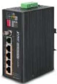
natural_image
Exterior view of a black industrial electronic device with multiple ports and a green top (no visible text or symbols)
DIN Rail Kit x 1 Wall-mount Kit x 1
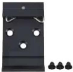
natural_image
Black plastic door with three white circular holes and a separate row of three small black objects (no text or symbols visible)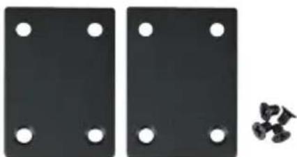
natural_image
Two black rectangular panels with six circular holes, and a cluster of small black fragments on the right side (no text or symbols)If any of these are missing or damaged, please contact your dealer immediately; if possible, retain the carton including the original packing material, and use them again to repack the product in case there is a need to return it to us for repair.
2. Application Diagram
PLANET Long Reach PoE solution is designed to extend IP Ethernet transmission and inject power simultaneously into a remote 802.3af/at PoE compliant powered device (PD) beyond the 100 meters distance limit of Ethernet. The solution works in pairs for point to point and point to multipoint connectivity.
The LRP-104CET supports two ways as power source to inject 802.3af/at PoE to remote standard PDs (Powered Devices).
- Remote LRP Power from LRP Injector/switch over coaxial cable
- Local DC power from power supply through LRP-104CET's terminal block
In the following application topologies, users can find the suitable wa extend the distance and power on the remote PDs.
2.1 Point to Multi-point
Remote LRP Power through BNC/RJ45 with DC 56V input or Local Power with External DC input (DC 24V\~48V)
2.1.1 LRP-101CH to LRP-104CET
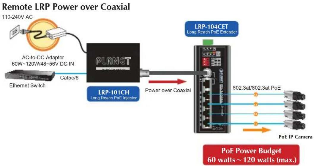
flowchart
graph LR
    A["110-240V AC"] --> B["AC-to-DC Adapter 60W~120W/48~56V DC IN"]
    B --> C["Ethernet Switch"]
    C --> D["Cat5e/6"]
    D --> E["PLANET"]
    E --> F["LRP-101CH Long Reach PoE Injector"]
    F --> G["Power over Coaxial"]
    G --> H["Long Reach PoE Extender"]
    H --> I["802.3af/802.3at PoE"]
    I --> J["PoE IP Camera"]
    H --> K["PoE Power Budget 60 watts ~ 120 watts (max.)"]
Local Power
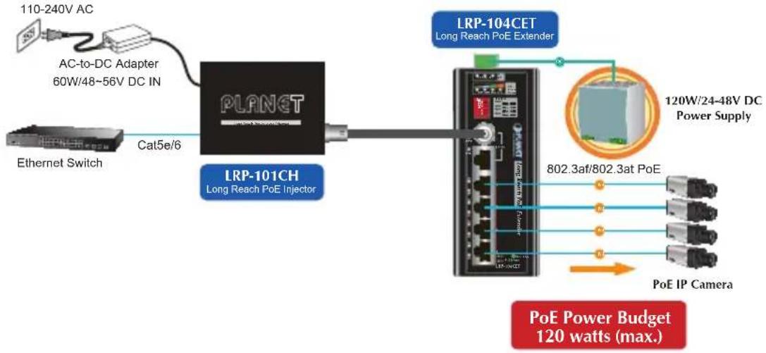
flowchart
graph LR
    A["Ethernet Switch"] -->|Cat5e/6| B["PLANET"]
    C["110-240V AC"] --> D["AC-to-DC Adapter 60W/48~56V DC IN"]
    B --> E["Long Reach PoE Injector"]
    E --> F["LRP-101CH"]
    F --> G["Long Reach PoE Extender"]
    G --> H["120W/24-48V DC Power Supply"]
    H --> I["802.3af/802.3at PoE"]
    I --> J["PoE IP Camera"]
    H --> K["PoE Power Budget 120 watts (max.)"]
2.1.2 LRP-101UH to LRP-104CET
Remote LRP Power over UTP
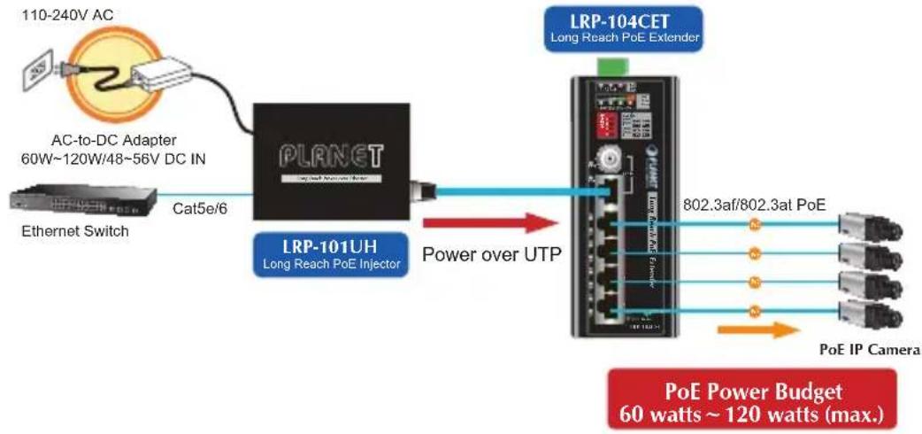
flowchart
graph LR
    A["110-240V AC"] --> B["AC-to-DC Adapter 60W~120W/48~56V DC IN"]
    B --> C["Ethernet Switch"]
    C --> D["Cat5e/6"]
    D --> E["PLANET"]
    E --> F["Long Reach PoE Injector"]
    F --> G["Power over UTP"]
    G --> H["LRP-104CET"]
    H --> I["Long Reach PoE Extender"]
    I --> J["802.3af/802.3at PoE"]
    I --> K["PoE IP Camera"]
    J --> L["PoE Power Budget 60 watts ~ 120 watts (max.)"]
Local Power
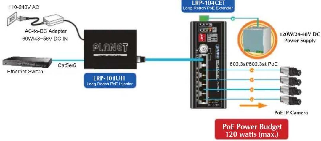
flowchart
graph LR
    A["Ethernet Switch"] -->|Cat5e/6| B["PLANET"]
    C["110-240V AC"] --> D["AC-to-DC Adapter 60W/48~56V DC IN"]
    B --> E["Long Reach PoE Extender"]
    E --> F["120W/24-48V DC Power Supply"]
    F --> G["802.3af/802.3at PoE"]
    G --> H["PoE IP Camera"]
    I["LRP-101UH Long Reach PoE Injector"] --> E
    J["LRP-104CET Long Reach PoE Extender"] --> E
    K["PoE Power Budget 120 watts (max.)"] --> G
2.2 Multi-Point to Multi-Point
Remote power LRP Power through BNC with DC 56V input or Local Power with External DC input (DC 24V\~48V)
2.2.1 LRP-822CS/LRP-1622CS to LRP-104CET
Remote LRP Power
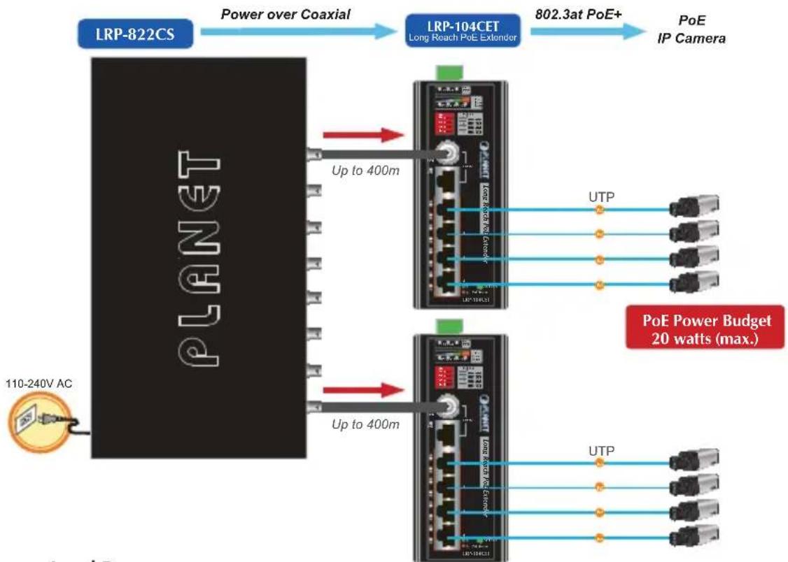
flowchart
graph LR
    A["110-240V AC"] --> B["PLANET"]
    B --> C["LRP-822CS"]
    C --> D["Power over Coaxial"]
    D --> E["LRP-104CET"]
    E --> F["802.3at PoE+"]
    F --> G["PoE IP Camera"]
    B --> H["Up to 400m"]
    E --> I["Up to 400m"]
    H --> J["UTP"]
    I --> K["UTP"]
    J --> L["PoE Power Budget 20 watts (max.)"]
    K --> M["PoE IP Camera"]
Local Power
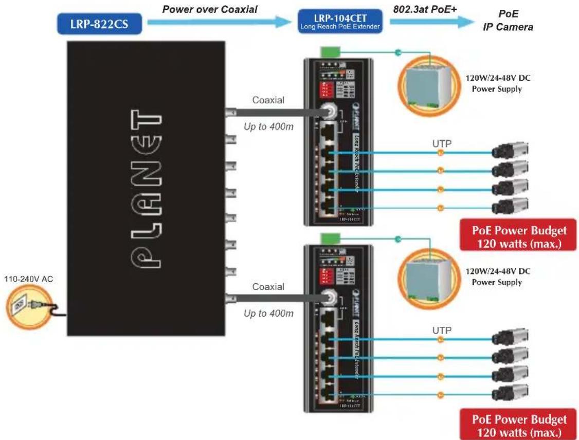
flowchart
graph LR
    A["110-240V AC"] --> B["PLA"]
    B --> C["LRP-822CS"]
    C --> D["Power over Coaxial"]
    D --> E["LRP-104CET"]
    E --> F["802.3at PoE+"]
    F --> G["PoE IP Camera"]
    B --> H["Coaxial"]
    B --> I["Coaxial"]
    H --> J["Up to 400m"]
    I --> K["Up to 400m"]
    J --> L["120W/24-48V DC Power Supply"]
    K --> M["120W/24-48V DC Power Supply"]
    L --> N["UTP"]
    M --> O["UTP"]
    N --> P["120W/24-48V DC Power Supply"]
    O --> Q["120W/24-48V DC Power Supply"]
    P --> R["120W/24-48V DC Power Supply"]
    Q --> S["120W/24-48V DC Power Supply"]
    R --> T["120W/24-48V DC Power Supply"]
    S --> U["120W/24-48V DC Power Supply"]
    T --> V["120W/24-48V DC Power Supply"]
    U --> W["120W/24-48V DC Power Supply"]
    V --> X["120W/24-48V DC Power Supply"]
    W --> Y["120W/24-48V DC Power Supply"]
    X --> Z["120W/24-48V DC Power Supply"]
    Y --> AA["120W/24-48V DC Power Supply"]
    Z --> AB["120W/24-48V DC Power Supply"]
    AA --> AC["120W/24-48V DC Power Supply"]
    AB --> AD["120W/24-48V DC Power Supply"]
    AC --> AE["120W/24-48V DC Power Supply"]
    AD --> AF["120W/24-48V DC Power Supply"]
    AE --> AG["120W/24-48V DC Power Supply"]
    AF --> AH["120W/24-48V DC Power Supply"]
    AG --> AI["120W/24-48V DC Power Supply"]
    AH --> AJ["120W/24-48V DC Power Supply"]
    AI --> AK["120W/24-48V DC Power Supply"]
    AJ --> AL["120W/24-48V DC Power Supply"]
    AK --> AM["120W/24-48V DC Power Supply"]
    AL --> AN["120W/24-48V DC Power Supply"]
    AM --> AO["120W/24-48V DC Power Supply"]
    AN --> AP["120W/24-48V DC Power Supply"]
    AO --> AQ["120W/24-48V DC Power Supply"]
    AP --> AR["120W/24-48V DC Power Supply"]
    AQ --> AS["120W/24-48V DC Power Supply"]
    AR --> AT["120W/24-48V DC Power Supply"]
    AS --> AU["120W/24-48V DC Power Supply"]
    AT --> AV["120W/24-48V DC Power Supply"]
    AU --> AW["120W/24-48V DC Power Supply"]
    AV --> AX["120W/24-48V DC Power Supply"]
    AW --> AY["120W/24-48V DC Power Supply"]
    AX --> AZ["120W/24-48V DC Power Supply"]
    AY --> BA["120W/24-48V DC Power Supply"]
    AZ --> BB["120W/24-48V DC Power Supply"]
3. Hardware Introduction
3.1 Physical Dimensions
■ LRP-104CET LRP Extender dimensions (W x D x H): 135 x 87.8 x 56mm
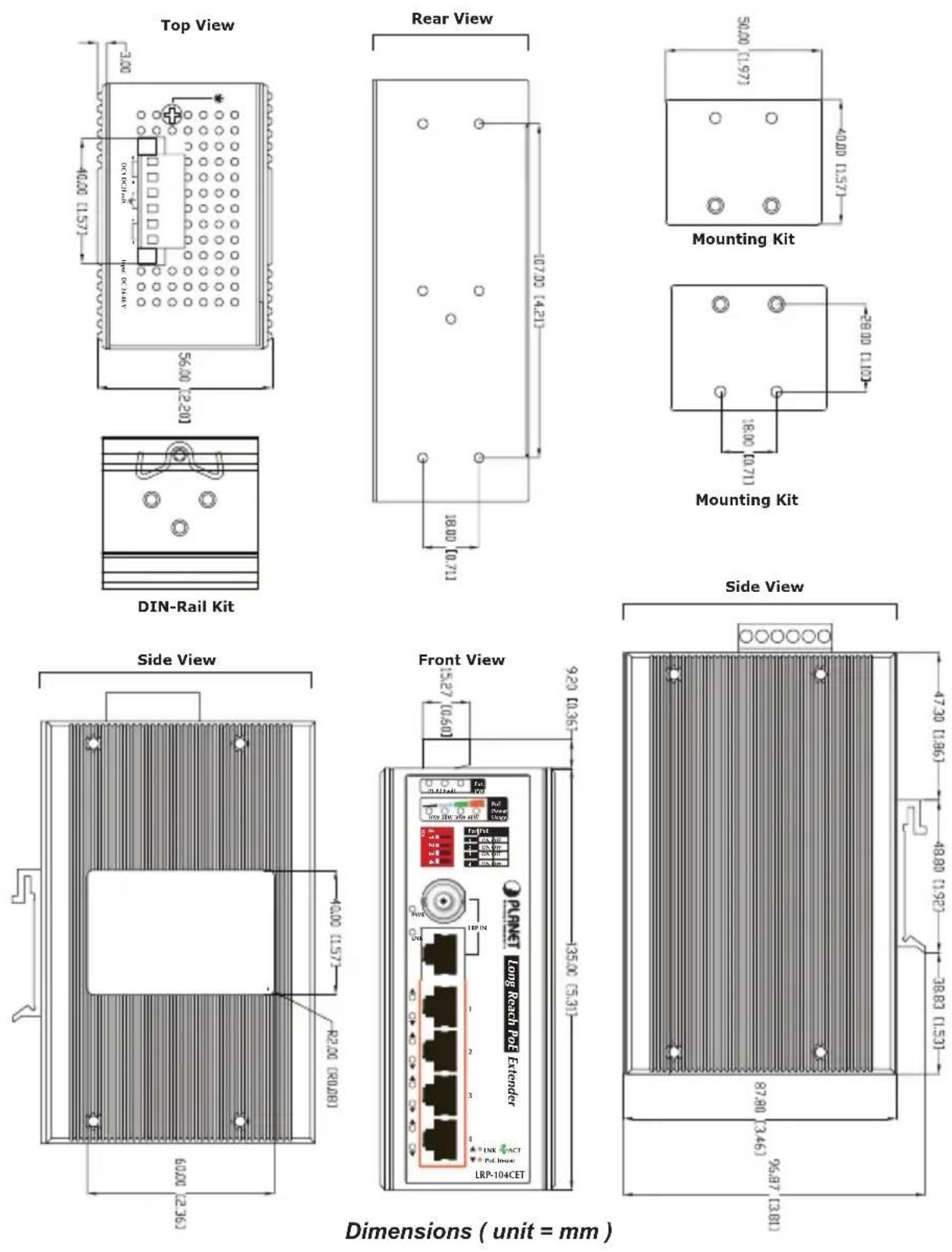
Figure 3-1: shows the front panel of LRP Extender
3.2 Front Panel
The front panel of the LRP Extender consists of 1BNC female/RJ45 connector and 4 10/100BASE-TX RJ45 ports. The LED Indicators are also located on the RJ45 ports of LRP-104CET
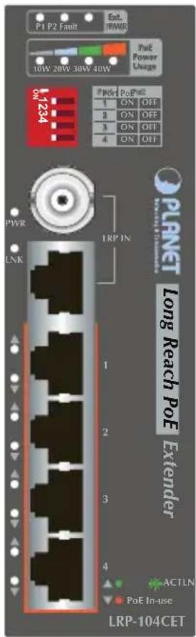
Figure 3-2: LRP-104CET Front Panel
3.3 The Upper Panel
The upper panel of the LRP Extender consists of one terminal block connector within two DC power inputs.
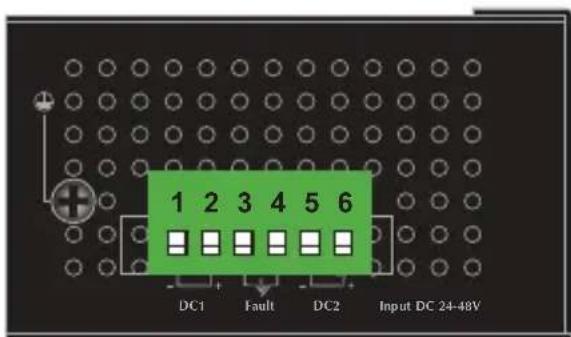
Figure 3-3: LRP Extender Upper Panel
3.4 LED Indicators
External Power Supply
| LED Color Function | |
| P1 Green Lights to indicate power 1 has power. | |
| P2 Green Lights to indicate power 2 has power. | |
| FAULT Red | Lights to indicate either power 1 or power 2 has no power. |
PoE Usage
| LED Color Function | ||
| 10W Green Lights | to indicate the power usage is ≥ 10W. | |
| 20W Green Lights | to indicate the power usage is ≥ 20W. | |
| 30W Green Lights | to indicate the power usage is ≥ 30W. | |
| 40W Green Lights | to indicate the power usage is ≥ 40W. | |
LRP Interface
| LED Color Function | |
| PWR Green Lights to indicate the power is on. | |
| LNK Green | Lights to indicate that the Coaxial/UTP link is established.Off: indicates that the Coaxial/UTP link is down. |
RJ45 10/100 BASE-TX Interface
| LED Color Function | ||
| PoE In-Use | Orange | Lights to indicate the RJ45 port is providing PoE power. |
| 10/100 LNK/ACT | Green | Lights to indicate the link through that port is successfully established at 10/100Mbps.Blinks to indicate that the port is actively sending or receiving data.Off: indicates that the port is link down. |
3.5 PoE DIP Switch Indication
The LRP Extender provides an adjustable switch that can be used to control the operation of the PoE output.
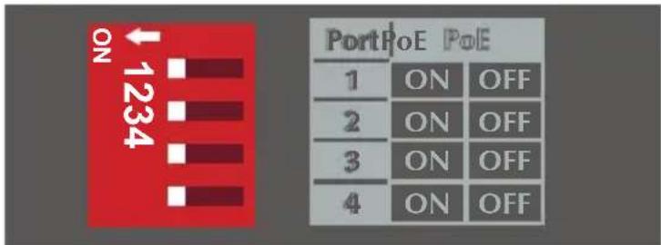
| Port 1 | ON (default) Port-1 PoE | Enable |
| OFF Port-1 PoE Disable | ||
| Port 2 | ON (default) Port-2 PoE | Enable |
| OFF Port-2 PoE Disable | ||
| Port 3 | ON (default) Port-3 PoE | Enable |
| OFF Port-3 PoE Disable | ||
| Port 4 | ON (default) Port-4 PoE | Enable |
| OFF Port-4 PoE Disable |

Note
For example, if administrator wants to stop remote Powered device of port1, simply turn the switch OFF to stop the output power.

Caution
When you turn off the PoE function of any ports, per port output will not enhance the output capacity.
4. Hardware Specifications
| Model LRP-104CET | |||
| Hardware Specifications | |||
| Ethernet Interface | Copper Ports | Four 10/100BASE-TX RJ45 auto-MDI/MDI-X | |
| PoE Injector Ports | Four ports with 802.3at/af PoE injector function with Port-1 to Port-4 | ||
| Functionality | Four DIP switches to control PoE output on or off with Port-1 to Port-4 | ||
| PoE Standards Compliance | IEEE 802.3at Power over Ethernet Plus/PSE | ||
| PoE Type End-span | |||
| PoE Power output | 52V DC, PoE output depends on LRP Injector or LRP Switch | ||
| 52V DC, 25-watt per port (External DC input) | |||
| Cabling | Ethernet : 10BASE-T: 2-pair UTP Cat.3, 4 and 5 Ethernet : 100BASE-TX: 2-pair UTP Cat.5, 5e and 6 | ||
| Maximum Distance 100m | |||
| Maximum Frame size | 1522 bytes | ||
| Long Reach PoE Interface | Connectivity | One BNC female Long Reach PoE over Coaxial PD (Powered Device) | One RJ45 connector Long Reach PoE over UTP PD (Powered Device) |
| Power Input 44~56V | DC | ||
| Power Pin Assignment | BNC center pole: DC+ BNC shield: DC- | RJ45 Pin 1, 3, 5, 7: VCC+ RJ45 Pin 2, 4, 6, 8: VCC- | |
| Long Reach PoE Interface | Cabling | Coaxial cable: 75 ohmRG-6/U cable, less than12Ω/1000 ftRG-59/U cable, less than 30Ω/1000 ft. | Cat. 3, 4, 5, 5e UTP cable (100 meters, max.)EIA/TIA-568100-ohm STP (100 meters, max.) |
| Maximum Distance | Max. 200m with PoE+ output (656ft.)Max. 400m with PoE output (1,312ft.)Max. 1000m without PoE output (3,280ft.) | Max. 100m with PoE+ output (328ft.)Max. 400m with PoE output (1,312ft.) | |
| Long Reach Ethernet Standard | IEEE 1901 | ||
| Modulation Type Wavelet-OFDM | |||
| Security 128-bit AES encryption | |||
| Frequency Band 2~28 MHz | |||
| Encryption AES 128-bit | |||
| LRP Compatibility | With power over coaxial input:• LRP-101CH - 1-Port LRP Injector• LRP-822CS - 8-Port LRP over Coax Switch• LRP-1622CS - 16-Port LRP over Coax Switch | With power over UTP input:• LRP-101UH - 1-Port LRP Injector | |
| LED Indicator | 3 x LED for External power supply: | Green: DC Power 1 | |
| Green: DC Power 2 | |||
| Red: Power Fault | |||
| 4 x LED for PoE Usage: | Green: 10W/20W/30W/40W | ||
| 2 x LED for Long Reach PoE In: | Green: PWR | ||
| Green: LNK | |||
| 2 x LED for each RJ45 interface (Port-1 and Port-4) | Green: 10/100Mbps LNK/ACT | ||
| Orange: PoE-in-use | |||
| Installation DIN | rail kit and wall mount kit | ||
| Dimensions (W x D x H) | 135 x 87.8 x 56 mm | ||
| Weight 644g | |||
| Power Requirements | 44~56V DC power over coaxial input | ||
| DC 24~48V, redundant power with polarity reverses protection function | |||
| Power Consumption/Dissipation | 130watts/446BTU (Ethernet with PoE Full Loading) | ||
| Alarm | One relay output for power failure. Alarm relay current carry ability: 1A @ 24V DC | ||
| Enclosure Aluminum metal case | |||
| Standards Conformance | |||
| Standards Compliance | IEEE 802.3 Ethernet/10BASE-TIEEE 802.3u Fast Ethernet/100BASE-TXIEEE 802.3x Full-Duplex Flow ControlIEEE 802.3at Power over Ethernet Plus | ||
| Regulatory Compliance | FCC Part 15 Class A, CE | ||
| Stability Testing | IEC60068-2-32 (free fall)IEC60068-2-27 (anti-shock)IEC60068-2-6 (anti-vibration) | ||
| Environment | |||||
| Temperature | Operating: -20~70 degrees CStorage: -20~70 degrees C | ||||
| Humidity | Operating: 5~95% (non-condensing)Storage: 5~95% (non-condensing) | ||||
| Performance | |||||
| Coaxial Performance | Distance | Data rate(Upload/Download) | 802.3af/at PoE Total Output Capability | ||
| Remote LRP power through BNC W/56VDC IN | Remote LRP power by LRP-822CS/LRP-1622CS | Local DC power through terminal block | |||
| 200m 91/88 Mbps 24W | 18W/19W 120W | ||||
| 400m 89/87 Mbps 21W | 14W/16W 120W | ||||
| 600m 83/81 Mbps 15W | 10W/12W 120W | ||||
| 800m 68/69 Mbps 11W | 7W/8W 120W | ||||
| 1000m 57/60 Mbps 8W | 120W | ||||
| UTP Performance | Distance | Data rate (Upload/Download) | 802.3af/at PoEtotal Output Capability | ||
| Remote LRP power through RJ45 W/56VDC IN | Local DC power through terminal block | ||||
| 100m 90/87Mbps 24W | 120W | ||||
| 200m 76/77Mbps 21W | 120W | ||||
| 300m 54/61Mbps 20W | 120W | ||||
| 400m 39/47Mbps 20W | 120W | ||||
| 500m | 14/18Mbps 20W | 120W | |||
* As there are various resistance values in the category of RG-59/U or RG-6/U cable, the actual data rate will vary on the quality of the copper wire and environment factors.
** Depending on what the DC/PoE Power Input and the length of coaxial cable are.
5. Installation Precautions
The LRP-104CET supports two ways as power source to inject 802.3af/at PoE to remote standard PDs.
● Remote LRP Power from LRP Injector/switch over coaxial/UTP cable
- Local DC power from power supply through LRP-104CET's terminal block
5.1 Installation Precautions of Remote Power by Coaxial Cable
When installing LRP PoE over coaxial injector, it only can work with PLANET LRP Extender, the LRP-104CET or LRP-101CE. Please confirm that other non-PoE equipment is not connected with the coaxial cable. When you connect the coaxial cable with coax-LAN converter, CCTV camera, etc, it might cause other equipment to damage.
| Note | All PLANET power over coaxial injectors or switches have the Warning Sticker, including LRP-101CH, LRP-822CS and LRP- 1622CS. |
5.2. Installation Precautions of Remote Power by UTP Cable
When installing LRP PoE over UTP injector, it only can work with PLANET LRP Extender, the LRP-104CET or LRP-101UE. Please confirm that other no equipment is not connected with the UTP cable. If connected with standard Ethernet equipment, it might cause damage to the equipment.
5.3 Installation Precautions of Local Power
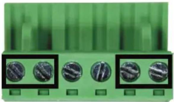
Installation of LRP injector or LRP switch. If you need to increase the PoE power budget of the LRP-104CET, you must use an external DC power supply. The 6-contact terminal block connector on the upper panel of LRP Extender is used for two DC redundant power inputs. Please follow the steps below to insert the power wire.

When the user is connected with an external power supply, the LRP-104CET will give priority to external power supply, LRP Injector or LRP Switch where data is transmitted to the LRP-104CET.

When performing any of the procedures like inserting the wires or tightening the wire-clamp screws, make sure the power is OFF to prevent from getting an electric shock.
- Insert positive and negative DC power wires into contacts 1 and 2 for POWER 1, or 5 and 6 for POWER 2.
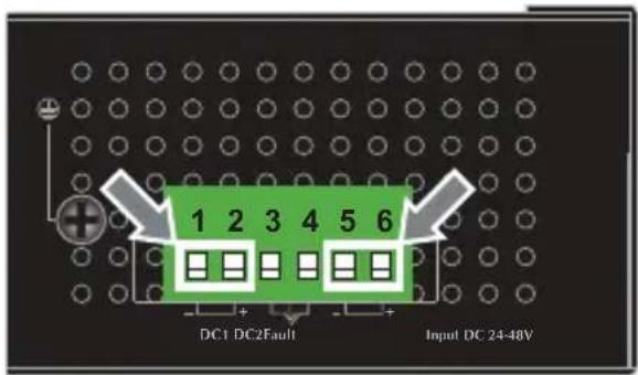
- Tighten the wire-clamp screws for preventing the wires from loosening.
natural_image
Close-up of a green electronic component with five circular slots, no visible text or symbols1 2 3 4 5 6
Power 1 Fault Power 2
- + - +

Note
- The wire gauge for the terminal block should be in the range between 12 and 24 AWG.
- The DC power input range is 24V \~ 48V DC.
5.4 Wiring the Fault Alarm Contact
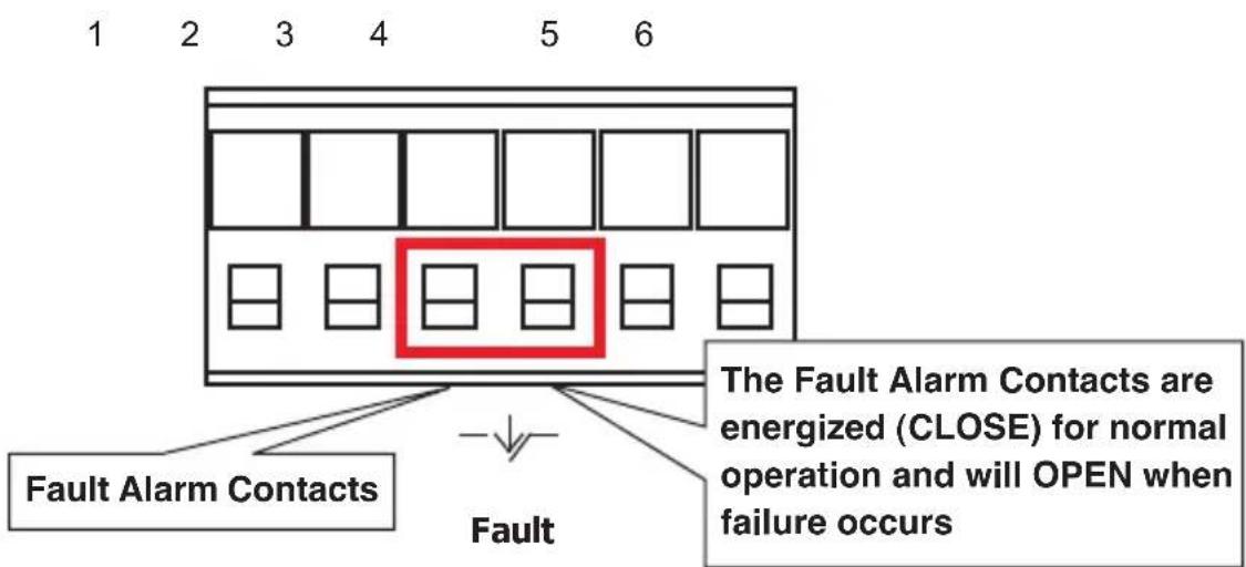
The fault alarm contacts are in the middle of the terminal block connector as the picture shows below. Inserting the wires, the LRP Extender will detect the fault status of the power failure and then forms an open circuit. The following illustration shows an application example for wiring the fault alarm contacts.
Insert the wires into the fault alarm contacts

Note
- The wire gauge for the terminal block should be in the range between 12 and 24 AWG.
- Alarm relay circuit accepts up to 24V, max. 1A currents.
6. Installation
This section describes the functionalities of the LRP Extender's components and guides you to how to install it. Basic knowledge of networking is expected. Please read this chapter completely before continuing.

Note
Before installation, please consider the distance and watts value demand for PD devices. The LRP-104CET output capacity and upload / download performance depends on the length of coaxial cable and UTP cable.

Note
When the remote PD's total power consumption is higher than LRP-104CET PoE power budget, the device will reboot and the LED Indicators will flash continuously. Please remove UTP cables of RJ45 ports to avoid the LRP-104CET to malfunction.
6.1 Applications of LRP-101CH or LRP Switch with coaxial cable
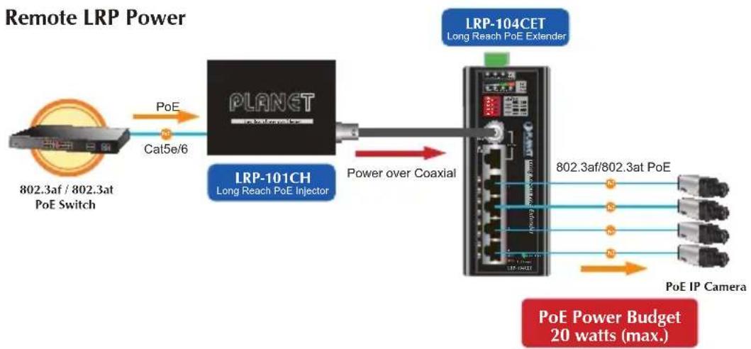
Type 1 One LRP-101CH with PoE power input and one LRP-104CET with PoE power output
The LRP Injector is powered via IEEE 802.3at/af PoE. An IEEE 802.3at/af compliant PoE PD will automatically be powered by the LRP Extender via UTP.
flowchart
graph LR
    A["802.3af / 802.3at PoE Switch"] -->|PoE| B["PLANET"]
    B --> C["Long Reach PoE Injector"]
    C --> D["Power over Coaxial"]
    D --> E["LRP-104CET"]
    E --> F["Long Reach PoE Extender"]
    F --> G["802.3af/802.3at PoE"]
    G --> H["PoE IP Camera"]
    H --> I["20 watts (max.)"]
    style A fill:#f9f,stroke:#333
    style B fill:#ccf,stroke:#333
    style C fill:#cfc,stroke:#333
    style D fill:#fcc,stroke:#333
    style E fill:#cff,stroke:#333
    style F fill:#ffc,stroke:#333
    style G fill:#cfc,stroke:#333
    style H fill:#fcc,stroke:#333
    style I fill:#ffc,stroke:#333
| Functions | LRP Injector LRP Extender | |
| LRP-101CH LRP-104CET | ||
| Power Input | RJ45 with 802.3at/af PoE input | BNC with DC power over coaxial input |
| Power Output | BNC with DC power over coaxial output | RJ45 with 802.3at/af PoE output |
Installation Instructions
Step 1. Connect the LRP Injector (LRP-101CH) and LRP Extender (LRP-104CET) to ends of BNC terminated coaxial cable.
Stick the "Warning Sticker" on the coaxial cable.
Step 2. Connect Cat5/6 UTP cable to LRP-101CH and IEEE 802.3at compliant PoE Switch or PoE Injector. If the PoE switch or PoE injector is powered on already, then the PWR LED of LRP-101CH and LRP-104CET should be lit up immediately.
Step 3. Connect Cat5/6 UTP cable to LRP-104CET and IEEE 802.3at/af complied PoE IP camera or PoE Wireless AP.

The LRP-101CH accepts IEEE 802.3at equipment for optimal power injection. The other non-standard PoE power devices may cause the LRP-101CH to malfunction.
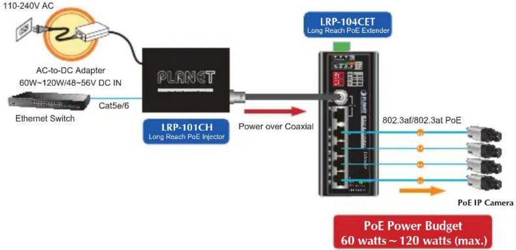
Type 2 One LRP-101CH with 48\~56V power adapter and one LRP-104CET with PoE power output
The LRP Injector is powered via the external power adapter. The IEEE 802.3at/af compliant PoE PD will automatically be powered by the LRP Extender via UTP.
Remote LRP Power over Coaxial
flowchart
graph LR
    A["110-240V AC"] --> B["AC-to-DC Adapter 60W~120W/48~56V DC IN"]
    B --> C["Ethernet Switch"]
    C --> D["Cat5e/6"]
    D --> E["PLANET"]
    E --> F["LRP-101CH Long Reach PoE Injector"]
    F --> G["Power over Coaxial"]
    G --> H["LRP-104CET Long Reach PoE Extender"]
    H --> I["802.3af/802.3at PoE"]
    I --> J["PoE IP Camera"]
    J --> K["PoE Power Budget 60 watts ~ 120 watts (max.)"]
| Functions | LRP Injector LRP Extender | |
| LRP-101CH LRP-104CET | ||
| Power Input | Power adapter with 48~56V DC in The LRP-101CH accepts up to 120W external power input | BNC with DC power over coaxial input |
| Power Output | BNC with DC power over coaxial output | RJ45 with 802.3at/af PoE output |
Installation Instructions
Step 1. Connect the LRP Injector (LRP-101CH) and LRP Extender (LRP-104CET) to ends of BNC terminated coaxial cable.
Stick the "Warning Sticker" on the coaxial cable.
Step 2. Connect Cat5/6 UTP cable to LRP-101CH and non-PoE switch or workstation.
Step 3. Connect 48\~56V DC power adapter to LRP-101CH power socket, then the PWR LED of LRP-101CH and LRP-104CET should be lit up immediately.
Step 4. Connect Cat5/6 UTP cable to LRP-104CET and IEEE 802.3at/af complied PoE IP camera or PoE Wireless AP.

- PoE output capacity is based on different DC Power Input / PoE Input.
- The LRP-101CH has two power input options; only one mode is available at one time. PoE power input cannot be used if power input of DC 52V or 56V is selected.
Type 3 One LRP-822CS/LRP-1622CS with AC power input and one LRP-104CET with PoE power output
The LRP Switch is powered via the AC power. The IEEE 802.3at/af compliant PoE PD will automatically be powered by the LRP Extender via UTP.
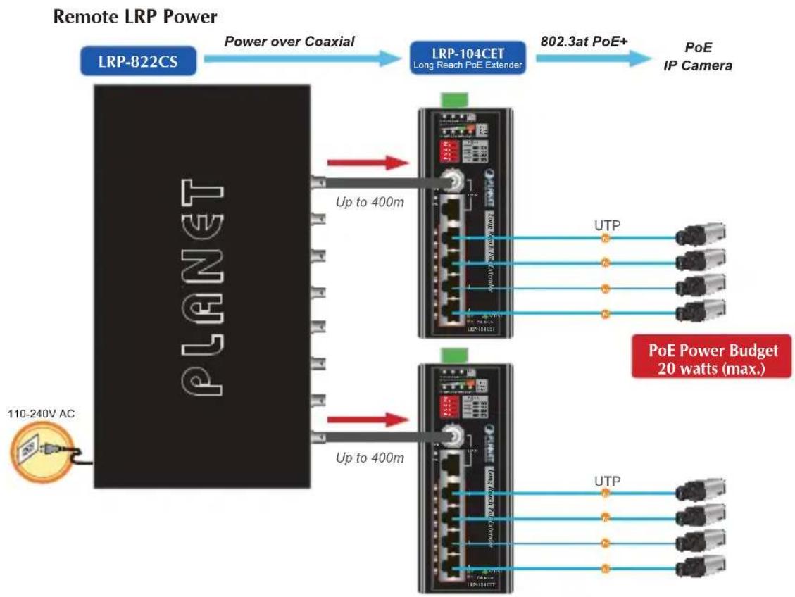
flowchart
graph LR
    A["110-240V AC"] --> B["PLANET"]
    B --> C["Up to 400m"]
    C --> D["LRP-822CS"]
    D --> E["Power over Coaxial"]
    E --> F["LRP-104CET"]
    F --> G["802.3at PoE+"]
    G --> H["PoE IP Camera"]
    C --> I["Up to 400m"]
    I --> J["Network Port"]
    J --> K["UTP"]
    J --> L["Network Port"]
    J --> M["Network Port"]
    J --> N["Network Port"]
    J --> O["Network Port"]
    J --> P["Network Port"]
    J --> Q["Network Port"]
    J --> R["Network Port"]
    J --> S["Network Port"]
    J --> T["Network Port"]
    J --> U["Network Port"]
    J --> V["Network Port"]
    J --> W["Network Port"]
    J --> X["Network Port"]
    J --> Y["Network Port"]
    J --> Z["Network Port"]
    J --> AA["Network Port"]
    J --> AB["Network Port"]
    J --> AC["Network Port"]
    J --> AD["Network Port"]
    J --> AE["Network Port"]
    J --> AF["Network Port"]
    J --> AG["Network Port"]
    J --> AH["Network Port"]
    J --> AI["Network Port"]
    J --> AJ["Network Port"]
    J --> AK["Network Port"]
    J --> AL["Network Port"]
    J --> AM["Network Port"]
    J --> AN["Network Port"]
    J --> AO["Network Port"]
    J --> AP["Network Port"]
    J --> AQ["Network Port"]
    J --> AR["Network Port"]
    J --> AS["Network Port"]
    J --> AT["Network Port"]
    J --> AU["Network Port"]
    J --> AV["Network Port"]
    J --> AW["Network Port"]
    J --> AX["Network Port"]
    J --> AY["Network Port"]
    J --> AZ["Network Port"]
    J --> BA["Network Port"]
    J --> BB["Network Port"]
    J --> BC["Network Port"]
    J --> BD["Network Port"]
    J --> BE["Network Port"]
    J --> BF["Network Port"]
    J --> BG["Network Port"]
    J --> BH["Network Port"]
    J --> BI["Network Port"]
    J --> BJ["Network Port"]
    J --> BK["Network Port"]
    J --> BL["Network Port"]
    J --> BM["Network Port"]
    J --> BN["Network Port"]
    J --> BO["Network Port"]
    J --> BP["Network Port"]
    J --> BQ["Network Port"]
    J --> BR["Network Port"]
    J --> BS["Network Port"]
    J --> BT["Network Port"]
    J --> BU["Network Port"]
    J --> BV["Network Port"]
    J --> BW["Network Port"]
    J --> BX["Network Port"]
    J --> BY["Network Port"]
    J --> BZ["Network Port"]
| Functions | LRP Switch LRP Extender | |
| LRP-822CS/LRP-1622CS LRP-104CET | ||
| Power Input | Power cord with AC 100~240V, 50/60Hz, auto-sensing | BNC with DC power over coaxial input |
| Power Output | BNC with DC power over coaxial output | RJ45 with 802.3at/af PoE output |
Installation Instructions
Step 1. Connect the LRP Switch (LRP-822CS/LRP-1622CS) and LRP Extender (LRP-104CET) to ends of BNC terminated coaxial cable.
Step 2. Connect 100\~240V AC power cord to LRP Switch (LRP-822CS/LRP-1622CS) power socket, then the PWR LED of LRP Switch (LRP-822CS/LRP-1622CS) should be lit up immediately.
The LRP Managed Switch is configured DISABLED Long Reach PoE function as default. So you must Enable Long Reach PoE function for all LRP ports from WebUI.
Step 3. After enabling the LRP function of LRP Switch (LRP-822CS/LRP-1622CS) from WebUI, the PWR LED of LRP-104CET should be lit up immediately.
Step 4. Connect Cat5/6 UTP cable to LRP-104CET and IEEE 802.3at/af complied PoE IP camera or PoE Wireless AP.

Additional advanced settings for the LRP Switch (LRP-822CS / LRP-1622CS) can be downloaded from the PLANET website or contact the PLANET support team.
6.2 Applications of LRP-101U-KIT with UTP/Twisted-pair Cable
Type 1 LRP-101UH with PoE power input and LRP-104CET with PoE power output
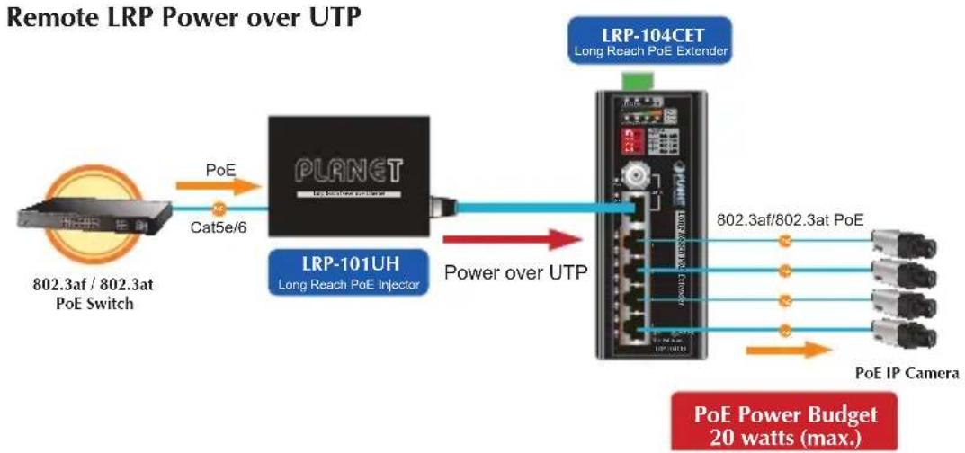
flowchart
graph LR
    A["802.3af / 802.3at PoE Switch"] -->|PoE| B["PLANET"]
    B --> C["LRP-101UH Long Reach PoE Injector"]
    C --> D["Power over UTP"]
    D --> E["LRP-104CET Long Reach PoE Extender"]
    E --> F["802.3af/802.3at PoE"]
    E --> G["PoE IP Camera"]
    E --> H["PoE Power Budget 20 watts (max.)"]
| Functions | LRP Injector LRP Extender | |
| LRP-101UH LRP-104CET | ||
| Power Input | RJ45 with 802.3at/af PoE input | UTP with DC power over UTP input |
| Power Output | UTP with DC power over UTP output | RJ45 with 802.3at/af PoE output |
Installation Instructions
Step 1. Remove the "Danger - No Ethernet" label stuck on the RJ45 LRP port of LRP-101UH.
Step 2. Connect the LRP Injector (LRP-101UH) and LRP Extender (LRP-104CET) to ends of RJ45 terminated long UTP/twisted-pair cable.

- Please do not connect any Ethernet equipment to LRP OUT Port of the LRP-101UH; otherwise, it will damage the Ethernet equipment.
- Please do not connect any Ethernet equipment to LRP IN Port of the LRP-104CET; otherwise, it will damage the Ethernet equipment.
Step 3. Connect Cat5/6 UTP cable to LRP-101UH and IEEE 802.3at compliant PoE Switch or PoE Injector. If the PoE switch or PoE injector is powered on already, then the PWR LED of LRP-101UH and LRP-104CET should be lit up accordingly.
Step 4. Connect Cat5/6 UTP cable to LRP-104CET and IEEE 802.3at/af complied PoE IP camera or PoE Wireless AP.

The LRP-101UH accepts IEEE 802.3at equipment for optimal power injection. The other non-standard PoE Power devices may cause the LRP-101UH to malfunction.

As there are various resistance values in the category 5/5e cable, the actual data rate will vary on the quality of the copper wire and environmental factors.
Type 2 LRP-101UH with 48\~56V power adapter and LRP-104CET with PoE power output
Remote LRP Power over UTP
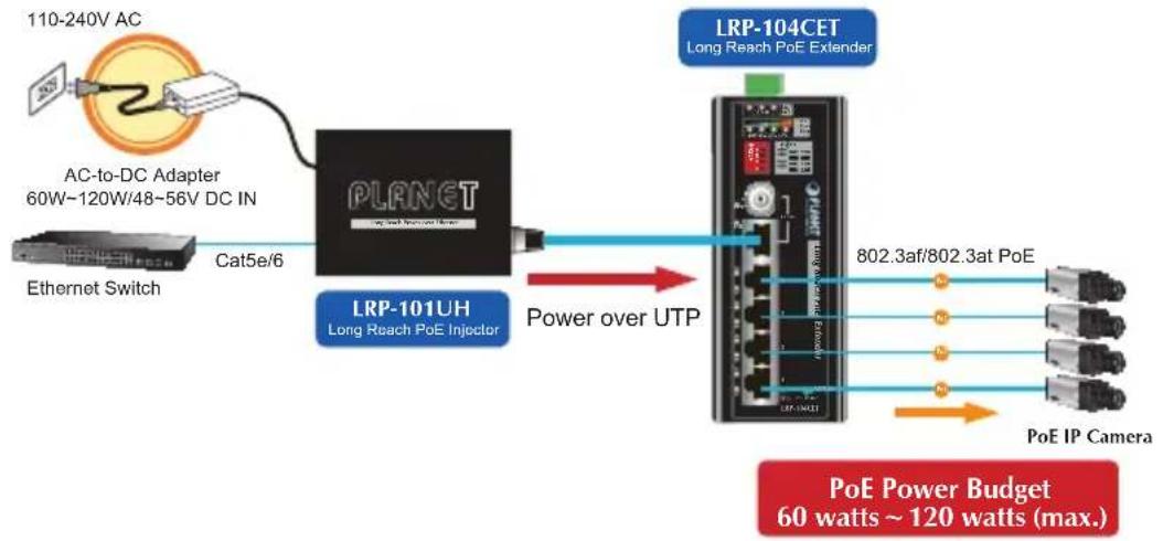
flowchart
graph LR
    A["110-240V AC"] --> B["AC-to-DC Adapter 60W~120W/48~56V DC IN"]
    B --> C["Ethernet Switch"]
    C --> D["Cat5e/6"]
    D --> E["PLANET"]
    E --> F["Long Reach PoE Injector"]
    F --> G["Power over UTP"]
    G --> H["LRP-101UH"]
    H --> I["Long Reach PoE Extender"]
    I --> J["802.3af/802.3at PoE"]
    J --> K["PoE IP Camera"]
    K --> L["PoE Power Budget 60 watts ~ 120 watts (max.)"]
| Functions | LRP Injector LRP Extender | |
| LRP-101UH LRP-104CET | ||
| Power Input | Power adapter with 48~56V DC in The LRP-101UH accepts up to 120W external power input | UTP with DC power over UTP input |
| Power Output | UTP with DC power over UTP output | RJ45 with 802.3at/af PoE output |
Installation Instructions
Step 1. Remove the "Danger - No Ethernet" label stuck on the RJ45 LRP ports of LRP-101UH.
Step 2. Connect the LRP Injector (LRP-101UH) and LRP Extender (LRP-104CET) to ends of RJ45 terminated long UTP/twisted-pair cable.

- Please do not connect any Ethernet equipment to LRP OUT Port of the LRP-101UH; otherwise, it will damage the Ethernet equipment.
- Please do not connect any Ethernet equipment to LRP IN Port of the LRP-104CET; otherwise, it will damage the Ethernet equipment.
Step 3. Connect Cat5/6 UTP cable to LRP-101UH and non-PoE switch or workstation.
Step 4. Connect 48\~56V DC power adapter to LRP-101UH power socket, and then the PWR LED of LRP-101UH and LRP-104CET should be lit up immediately.
Step 5. Connect Cat5/6 UTP cable to LRP-104CET and IEEE 802.3at/af complied PoE IP camera or PoE Wireless AP.

Note
- PoE output capacity is based on different DC Power Input / PoE Input.
- The LRP-101UH has two power input options; only one mode is available at one time. PoE power input cannot be used if power input of DC 52V or 56V is selected.
6.3 Applications of LRP Injector or LRP Switch powered by External DC power supply
The LRP-104CET can be powered via External DC 24\~48V input. You can refer to Section 5.3 for Installation Precautions of Local Power. This section describes its applications and precautions.

Note
When the External DC power in is used, the LRP-104CET can provide each port up to 25 watts of PoE output. The PoE power budget can be increased to 120 watts.
Type 1 One LRP-101CH and one LRP-104CET with PoE power output
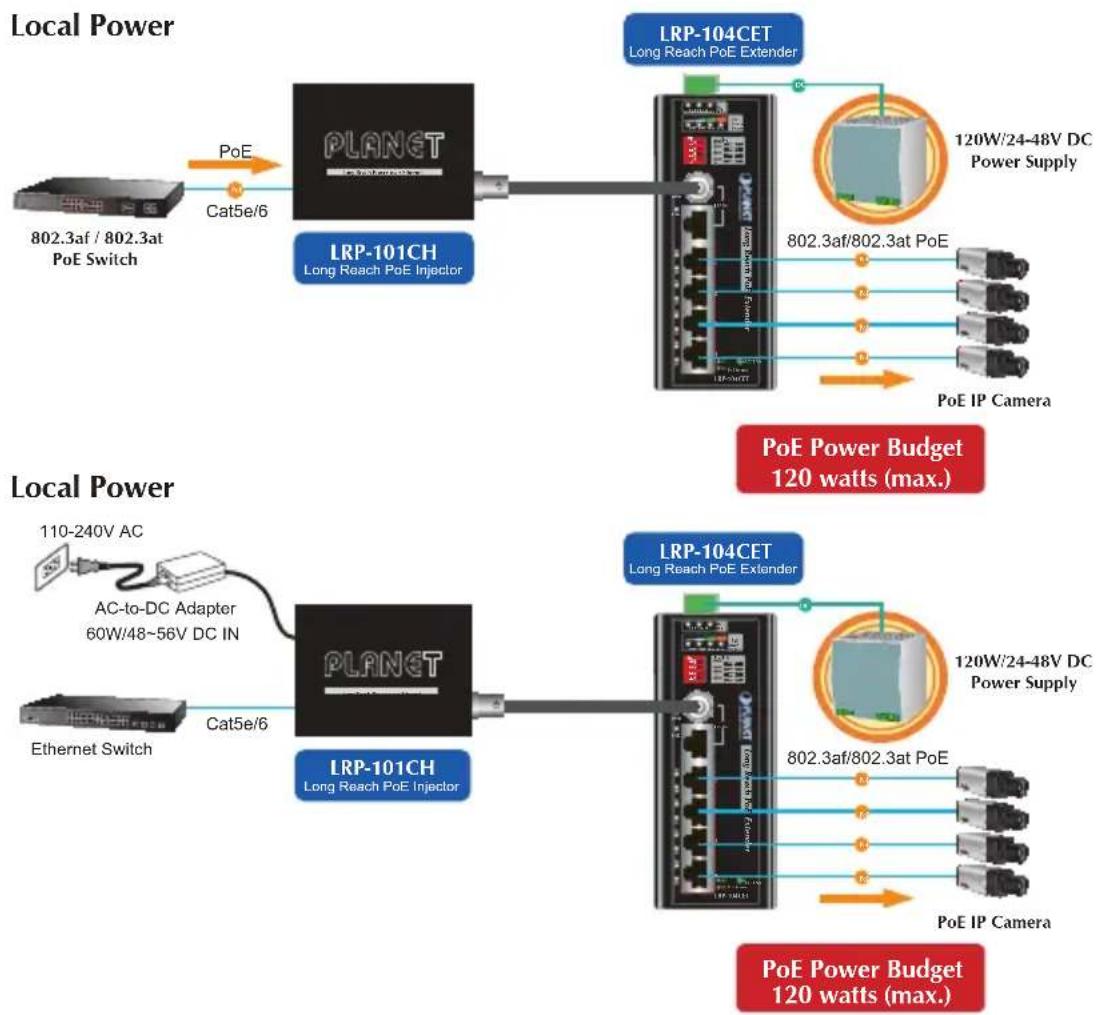
flowchart
graph TD
    A["802.3af / 802.3at PoE Switch"] -->|PoE| B["LP-101CH Long Reach PoE Injector"]
    B --> C["LP-104CET Long Reach PoE Extender"]
    C --> D["120W/24-48V DC Power Supply"]
    C --> E["802.3af/802.3at PoE"]
    C --> F["PoE IP Camera"]
    G["110-240V AC"] --> H["AC-to-DC Adapter 60W/48~56V DC IN"]
    H --> I["LP-101CH Long Reach PoE Injector"]
    I --> J["LP-104CET Long Reach PoE Extender"]
    J --> K["120W/24-48V DC Power Supply"]
    J --> L["802.3af/802.3at PoE"]
    J --> M["PoE IP Camera"]
    N["Ethernet Switch"] --> O["Cat5e/6"]
    P["Local Power"] --> Q["Local Power"]
    Q --> R["Local Power"]
    R --> S["Local Power"]
    S --> T["Local Power"]
| Functions | LRP Injector LRP Extender | |
| LRP-101CH LRP-104CET | ||
| Power Input | RJ45 with 802.3at/af PoE input | External DC 24~48V power input |
| Power adapter with 48~56V DC in | ||
| Power Output | BNC with DC power over coaxial output | RJ45 with 802.3at/af PoE output |

Warning
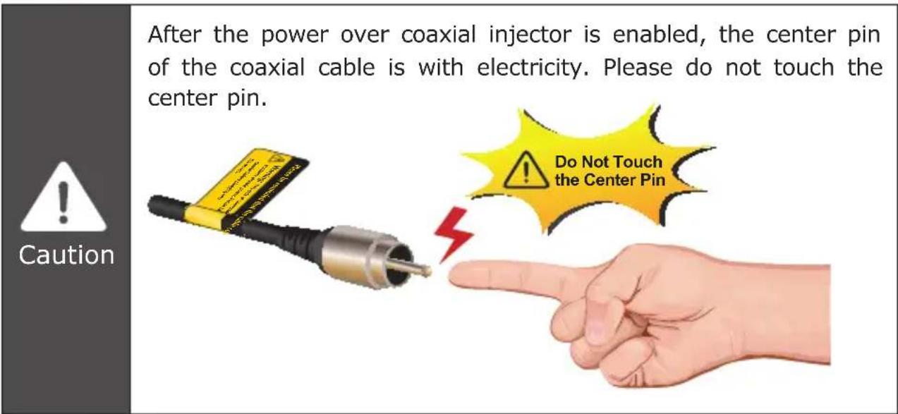
After the power over coaxial injector is enabled, the center pin of the coaxial cable has electricity. Please do not touch the center pin.
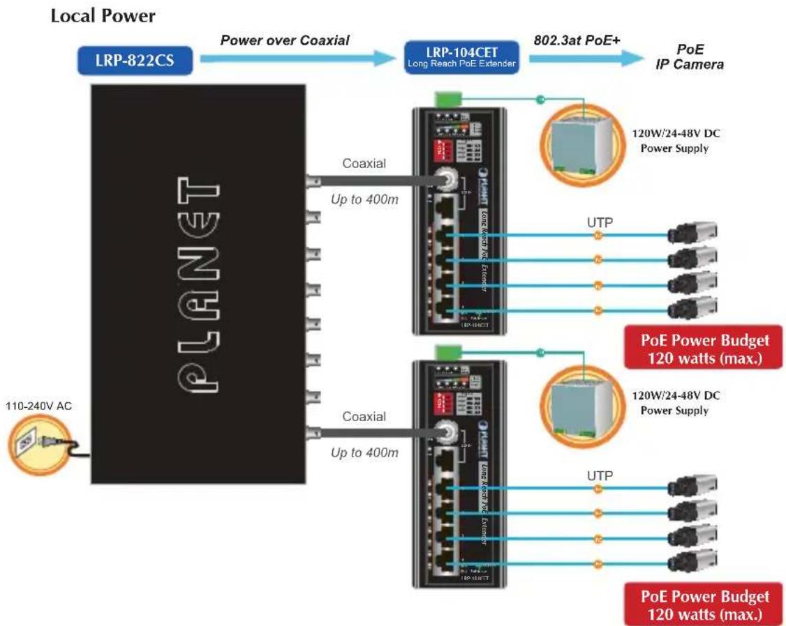
Type 2 One LRP-822CS/LRP-1622CS and one LRP-104CET with PoE power output
flowchart
graph LR
    A["Local Power"] -->|Power over Coaxial| B["LRP-822CS"]
    B --> C["Long Reach PoE Extender"]
    C --> D["PoE IP Camera"]
    D --> E["120W/24-48V DC Power Supply"]
    D --> F["120W/24-48V DC Power Supply"]
    D --> G["120W/24-48V DC Power Supply"]
    H["110-240V AC"] --> I["PLANET"]
    I --> J["Coaxial"]
    I --> K["Coaxial"]
    J --> L["Up to 400m"]
    K --> M["Up to 400m"]
    L --> N["Coaxial"]
    M --> O["Coaxial"]
    N --> P["802.3at PoE+"]
    O --> Q["802.3at PoE+"]
    P --> R["PoE Power Budget 120 watts (max.)"]
    Q --> S["PoE Power Budget 120 watts (max.)"]
| Functions | LRP Switch LRP Extender | |
| LRP-822CS/LRP-1622CS LRP-104CET | ||
| Power Input | Power cord with AC 100~240V, 50/60Hz, auto-sensing | External DC 24~48V power input |
| Power Output | BNC with DC power over coaxial output | RJ45 with 802.3at/af PoE output |

Warning
After the power over coaxial injector is enabled, the center pin of the coaxial cable has electricity. Please do not touch the center pin.
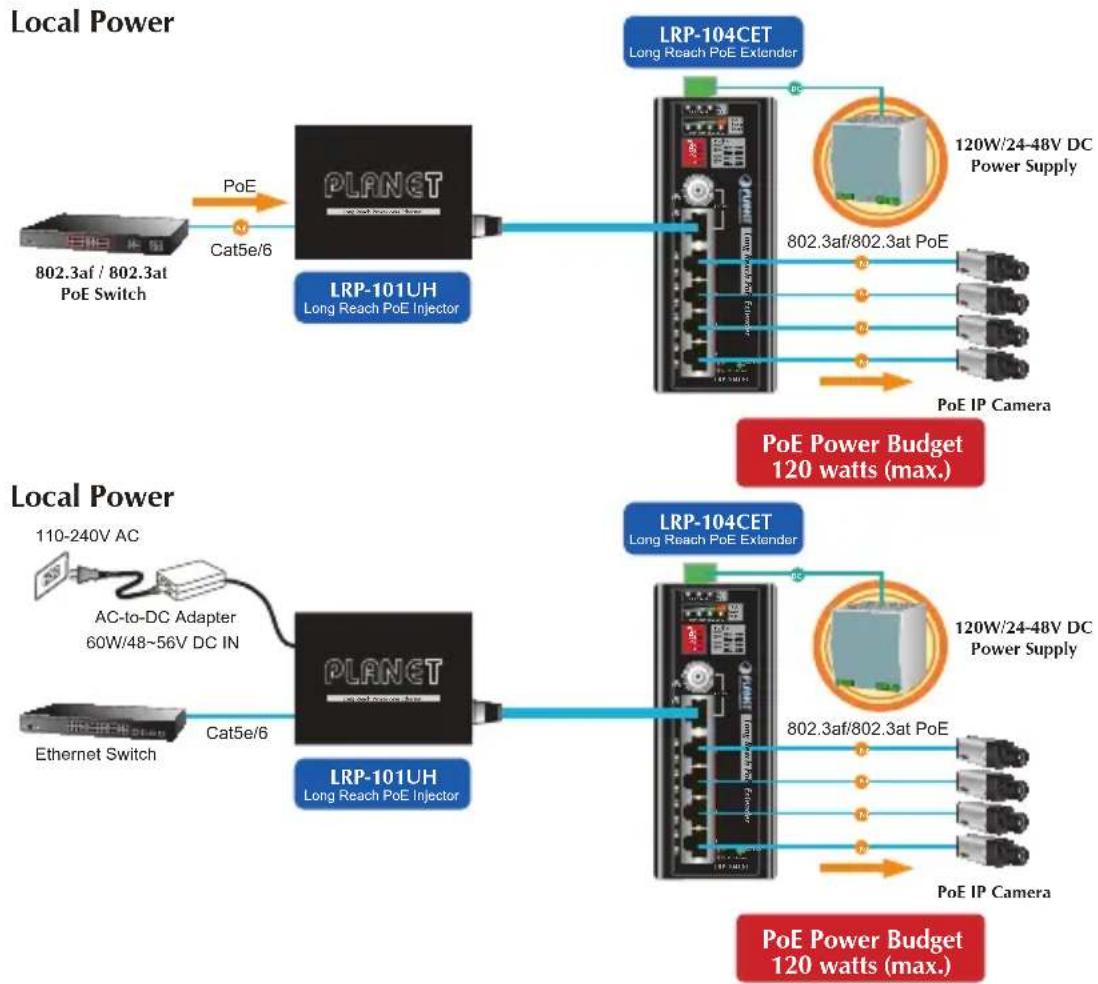
Type 3 LRP-101UH and LRP-104CET with PoE power output
flowchart
graph TD
    A["Local Power"] --> B["802.3af / 802.3at PoE Switch"]
    B --> C["PLANET"]
    C --> D["LRP-101UH Long Reach PoE Injector"]
    D --> E["PLANET"]
    E --> F["Long Reach PoE Extender"]
    F --> G["120W/24-48V DC Power Supply"]
    F --> H["802.3af/802.3at PoE"]
    F --> I["PoE IP Camera"]
    J["Local Power"] --> K["110-240V AC"]
    K --> L["AC-to-DC Adapter 60W/48~56V DC IN"]
    L --> M["PLANET"]
    M --> N["LRP-101UH Long Reach PoE Injector"]
    N --> O["PLANET"]
    O --> P["Long Reach PoE Extender"]
    P --> Q["120W/24-48V DC Power Supply"]
    P --> R["802.3af/802.3at PoE"]
    P --> S["PoE IP Camera"]
    T["Local Power"] --> U["Ethernet Switch"]
    U --> V["Cat5e/6"]
    V --> W["PLANET"]
    W --> X["LRP-101UH Long Reach PoE Injector"]
    X --> Y["PLANET"]
    Y --> Z["Long Reach PoE Extender"]
    Z --> AA["120W/24-48V DC Power Supply"]
    Z --> AB["802.3af/802.3at PoE"]
    Z --> AC["PoE IP Camera"]
    AD["PoE Power Budget 120 watts (max.)"] --> AE["Local Power"]
    AF["PoE Power Budget 120 watts (max.)"] --> AG["Local Power"]
| Functions | LRP Injector LRP Extender | |
| LRP-101UH LRP-104CET | ||
| Power Input | RJ45 with 802.3at/af PoE input | External DC 24~48V power input |
| Power adapter with 48~56V DC in | ||
| Power Output | UTP with DC power over UTP output | RJ45 with 802.3at/af PoE output |

Warning
-
Please do not connect any Ethernet equipment to LRP OUT Port of the LRP-101UH; otherwise, it will damage the Ethernet equipment.
-
Please do not connect any Ethernet equipment to LRP IN Port of the LRP-104CET; otherwise, it will damage the Ethernet equipment.
Appendix A: Networking Connection
A.1 Switch's RJ45 Pin Assignments
10/100Mbps, 10/100BASE-TX
| RJ45 Connector pin assignment | |||
| Contact | MDIMedia DependentInterface | MDI-XMedia DependentInterface-Cross | PoE |
| 1 Tx + (transmit) Rx + (receive) Positive (VCC+) | |||
| 2 Tx - (transmit) Rx - (receive) Positive (VCC+) | |||
| 3 Rx + (receive) Tx + (transmit) Negative (VCC-) | |||
| 4, 5 Not used Not used | |||
| 6 Rx - (receive) Tx - (transmit) Negative (VCC-) | |||
| 7, 8 Not used Not used | |||
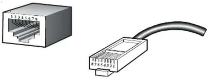
A.2 RJ45 Cable Pin Assignments
natural_image
Two types of Ethernet connectors shown: one with a 12-pin connector and the other with a curved cable (no text or symbols)The standard RJ45 receptacle/connector
There are 8 wires on a standard UTP/STP cable and each wire is color-coded. The following shows the pin allocation and color of straight cable and crossover cable connection:
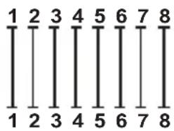
Straight Cable
1 = White/Orange
2 = Orange
3 = White/Green
4 = Blue
5 = White/Blue
6 = Green
7 = White/Brown
8 = Brown
SIDE 2
1 = White/Orange
2 = Orange
3 = White/Green
4 = Blue
5 = White/Blue
6 = Green
7 = White/Brown
8 = Brown
Cross Over Cable
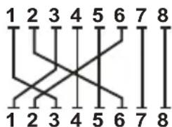
1 = White/Orange
2 = Orange
3 = White/Green
4 = Blue
5 = White/Blue
6 = Green
7 = White/Brown
8 = Brown
1 = White/Green
2 = Green
3 = White/Orange
4 = Blue
5 = White/Blue
6 = Orange
7 = White/Brown
8 = Brown
Figure A-1: Straight-through and Crossover Cable
Please make sure your connected cables are with the same pin assignment and color as the above picture before deploying the cables into your network.
- Industrial 1-Port Coax/UTP Long Reach PoE+ 4-Port
- 10/100TX PoE Extender
- Table of Contents
- Package Contents
- Application Diagram
- Point to Multi-point
- LRP-101CH to LRP-104CET
- LRP-101UH to LRP-104CET
- Multi-Point to Multi-Point
- LRP-822CS/LRP-1622CS to LRP-104CET
- Hardware Introduction
- Physical Dimensions
- Front Panel
- The Upper Panel
- LED Indicators
- PoE DIP Switch Indication
- Hardware Specifications
- Installation Precautions
- Installation Precautions of Remote Power by Coaxial Cable
- Installation Precautions of Remote Power by UTP Cable
- Installation Precautions of Local Power
- Wiring the Fault Alarm Contact
- Installation
- Applications of LRP-101CH or LRP Switch with coaxial cable
- Installation Instructions
- Applications of LRP-101U-KIT with UTP/Twisted-pair Cable
- Applications of LRP Injector or LRP Switch powered by External DC power supply
- Warning
- Appendix A: Networking Connection
- A.1 Switch's RJ45 Pin Assignments
- A.2 RJ45 Cable Pin Assignments
Brand : Planet
Model : LRP-104CET
Category : Wi-Fi repeater