
Storage System JBOD2312S3SP - Disk array INTEL - Free user manual and instructions
Find the device manual for free Storage System JBOD2312S3SP INTEL in PDF.


| Product Type | Disk Array (JBOD) |
| Model | JBOD2312S3SP |
| Form Factor | 2U Rackmount |
| Drive Bays | 12 x 3.5" Hot-Swap |
| Supported Drives | SAS/SATA HDD or SSD: 12Gb/s, 6Gb/s, 3Gb/s SAS; 3Gb/s, 6Gb/s SATA |
| SAS Expander | 36-port 12Gb/s SAS Expander (Intel RES3FV288) |
| Backplane Type | Single-port (standard) or dual-port (optional) |
| Power Supply | 460W AC (1+1 redundant optional) |
| Power Supply Efficiency | 92% at 50% load |
| System Fans | 4 x 60mm hot-swappable fans |
| External SAS Ports | 2 x SFF-8644 (12Gb/s) |
| Dimensions (W x H x D) | 482.6 mm x 87.6 mm x 667.3 mm |
| Operating Temperature | 10°C to 35°C (ASHRAE A2), up to 45°C short-term |
| Input Voltage | AC 90-132V / 180-264V auto-ranging |
| AC Power Cord Spec | SJT 16 AWG, 125V, 13A |
| Auto Power On | Configurable via jumper (enabled/disabled) |
| Enclosure Management | SES (SCSI Enclosure Services) via SMBus |
| Hot-Swap Support | Drives, fans, and power supplies |
| LED Indicators | Power, system status, drive activity/fault |
| Cascade Support | Up to 2 layers daisy-chain |
Frequently Asked Questions - Storage System JBOD2312S3SP INTEL
User questions about Storage System JBOD2312S3SP INTEL
0 question about this device. Answer the ones you know or ask your own.
Ask a new question about this device
Download the instructions for your Disk array in PDF format for free! Find your manual Storage System JBOD2312S3SP - INTEL and take your electronic device back in hand. On this page are published all the documents necessary for the use of your device. Storage System JBOD2312S3SP by INTEL.
USER MANUAL Storage System JBOD2312S3SP INTEL
Intel® Storage System JBOD2312S3SP
Hardware Guide
A document providing a system level overview of product features, functions, architecture, and support specifications
Revision 1.3
Mar 2016
Intel® Server Boards and Systems
(This page is intentionally left blank.)
Revision History
| Date | Revision Number | Modifications |
| November 2014 | 0.9 | Pre-production release. |
| December 2014 | 1.0 | Production version release. |
| May 2015 | 1.1 | Removed references to PSU Cold Redundancy support. |
| October 2015 | 1.2 | Added optional PSU and power cable references in the Power Subsystem section. |
| March 2016 | 1.3 | Converted to the new format. |
Disclaimers
No license (express or implied, by estoppel or otherwise) to any intellectual property rights is granted by this document.
Intel disclaims all express and implied warranties, including without limitation, the implied warranties of merchantability, fitness for a particular purpose, and non-infringement, as well as any warranty arising from course of performance, course of dealing, or usage in trade.
This document contains information on products, services and/or processes in development. All information provided here is subject to change without notice. Contact your Intel representative to obtain the latest Hardware Guide.
The products and services described may contain defects or errors known as errata which may cause deviations from published specifications. Current characterized errata are available on request.
Intel, and the Intel logo are trademarks of Intel Corporation in the U.S. and/or other countries.
*Other names and brands may be claimed as the property of others
© 2016 Intel Corporation.
Table of Contents
1 Introduction....1
1.1 Server Product Use Disclaimer....1
1.2 Product Errata....1
2 Product Family Overview....2
2.1 Chassis Dimensions....3
2.2 System Level Environmental Limits....4
2.3 System Features and Options Overview....5
2.3.1 Hot Swap Hard Drive Bay 5
2.3.2 Front Control Panel....6
2.3.3 Back Panel Features....7
3 System Storage and Peripheral Drive Bay Overview....8
3.1 3.5" Hard Disk Drive Support....8
3.2 3.5" Drive Hot-Swap Backplane Overview....9
3.2.1 Cypress* CY8C22545 Enclosure Management Controller 10
4 Power Subsystem....11
4.1 Power Distribution Board (PDB)....12
4.2 Mechanical Overview.... 14
4.3 Power Connectors.... 16
4.3.1 Power Supply Module Card Edge Connector 16
4.3.2 Hot-Swap Backplane Power Connector....16
4.4 Power Supply Module Efficiency....17
4.5 AC Power Cord Specification Requirements.... 17
4.6 AC Input Specifications.... 17
4.6.1 Power Factor 17
4.6.2 AC Input Voltage Specification 18
4.6.3 AC Line Isolation Requirements....18
4.6.4 AC Line Dropout/Holdup 18
4.6.5 AC Line Fuse 19
4.6.6 AC Inrush....19
4.6.7 AC Line Transient Specification....19
4.6.8 Susceptibility Requirements....20
4.6.9 Electrostatic Discharge Susceptibility 20
4.6.10 Fast Transient/Burst 20
4.6.11 Radiated Immunity....20
4.6.12 Surge Immunity....20
4.6.13 Voltage Interruptions....20
4.6.14 Protection Circuits....21
4.6.15 Over Current Protection (OCP) 21
4.6.16 Over Voltage Protection (OVP) 21
4.6.17 Over Temperature Protection (OTP)....21
4.7 Power Supply Status LED 21
5 Thermal Management 23
5.1 Thermal Operation and Configuration Requirements....23
5.2 Thermal Management Overview....23
5.3 Thermal Sensor Input for Fan Speed Control....23
5.4 System Fans 24
5.5 Fan Speed Control....26
5.6 Power Supply Module Fan....26
6 JBOD2000S3SP Internal Connection Overview.... 27
6.1 Expander Board 27
6.1.1 JBOD SAS Expander Port Numbering 29
6.1.2 JBOD2312S3SP Interconnection....30
7 JBOD2000S3SP External SAS Connection Mode Overview 31
7.1 External SAS Controller Support 31
7.2 External SAS Cable 31
7.3 Hard Drive Type.... 32
7.4 JBOD Cascade....32
7.5 Single-port JBOD2000S3SP External Connection Mode 32
7.5.1 Single JBOD2000S3SP Connection....32
7.5.2 Two JBOD2000S3SP Cascade....33
7.5.3 Dual-path Connection....34
7.5.4 Dual-path with Cascaded JBOD2000S3SP 35
List of Figures
Figure 1. 12 x 3.5" Drive JBOD2000S3 Product Drawing....2
Figure 2. Chassis Dimensions....3
Figure 3. System Components Overview....5
Figure 4. 12 x 3.5" Drive JBOD2000S3SP Front View....5
Figure 5. Front Panel Options....6
Figure 6. JBOD2312S3SP Back View ....7
Figure 7.3.5" Hard Drive Bay – 12-Drive Configuration....8
Figure 8.3.5" Drive Tray Assembly ....8
Figure 9. Status and Activity LED on 3.5" Drive Tray....8
Figure 10.3.5" Hot-Swap Backplane and Drive Bay Assembly 9
Figure 11. SFF-8482 Connector on 3.5" HSBP....9
Figure 12. Components on 3.5" HSBP ....10
Figure 13. Power Supply Assembly ......11
Figure 14. Power Distribution Board (PDB)....12
Figure 15. PDB Component Placement....13
Figure 16. Fan Fault LED Block Diagram....14
Figure 17. Power Supply Module Mechanical Drawing....15
Figure 18. Power Supply Module ....15
Figure 19. AC Power Supply – Connector View....15
Figure 20. AC Power Cord ....17
Figure 21. System Fan Identification ....24
Figure 22. System Fan Assembly....25
Figure 23. Internal SAS Expander Location....28
Figure 24: SAS Expander Port Numbering ....29
Figure 25. 12x3.5" Single-port JBOD2000S3SP Interconnection Diagram....30
Figure 26. SFF-8644 mini-SAS Cable....31
Figure 27. Single JBOD2000S3SP Connection ....32
Figure 28. Two Single-port JBOD2000S3SP Cascade....33
Figure 29. Two Groups of Cascaded Single-port JBOD2000S3SP....33
Figure 30. Dual-path Connection....34
Figure 31. Dual-path with Cascaded JBOD2000S3SP....35
List of Tables
Table 1. System Environmental Limits Summary....4
Table 2. Power LED Functional States ......6
Table 3. System Status LED State Definitions....6
Table 4. Status LED Status....9
Table 5. Activity LED Status....9
Table 6: Auto Power On Jumper Options....13
Table 7. Power Supply Module Output Power Connector Pin-out....16
Table 8. Hot-swap Backplane Power Connector Pin-out ("HSBP PWR")......17
Table 9. 460 Watt Power Supply Efficiency .....17
Table 10. AC Power Cord Specifications....17
Table 11. Power Factor....18
Table 12. AC Input Voltage Range....18
Table 13. AC Line Dropout/Holdup....18
Table 14. AC Line Sag Transient Performance ......19
Table 15. AC Line Surge Transient Performance....19
Table 16. Performance Criteria....20
Table 17. 460 Watt Power Supply Over Current Protection ....21
Table 18. Over Voltage Protection (OVP) Limits....21
Table 19. LED Indicators ......22
Table 20. System Fan Connector Pin-out....25
Table 21: PWM Settings....26
Table 22: Temperature Notification Thresholds....26
Table 23: External Cable List ....36
< This page intentionally left blank. >
1 Introduction
This Hardware Guide provides system-level information for the Intel ^® Storage System JBOD2312S3SP.
This document describes the functions and features of this JBOD product and includes the chassis layout, system boards, power subsystem, cooling subsystem, storage subsystem options, and available installable options.
This document is divided into the following chapters:
■ Chapter 1 – Introduction
■ Chapter 2 –Product Family Overview
- Chapter 3 – System Storage and Peripheral Drive Bay Overview
■ Chapter 4 – Power Subsystem
■ Chapter 5 – Thermal Management
- Chapter 6 – JBOD2000S3SP Internal Connection Overview
- Chapter 7 – JBOD2000S3SP External SAS Connection Mode Overview
- Appendix A – Qualified External Mini-SAS Cable List
■ Reference Documents
1.1 Server Product Use Disclaimer
It is the responsibility of the system integrator who chooses not to use Intel-developed server building blocks to consult vendor datasheets and operating parameters to determine the amount of airflow required for their specific application and environmental conditions. Intel Corporation cannot be held responsible if components fail to operate correctly when used outside any of their published operating or non-operating limits.
1.2 Product Errata
The products described in this document may contain design defects or errors known as errata which may cause the product to deviate from published specifications. Product Errata are documented in the Intel ^® Storage System JBOD2312S3SP Monthly Specification Update which can be downloaded from http://www.Intel.com/support.
2 Product Family Overview
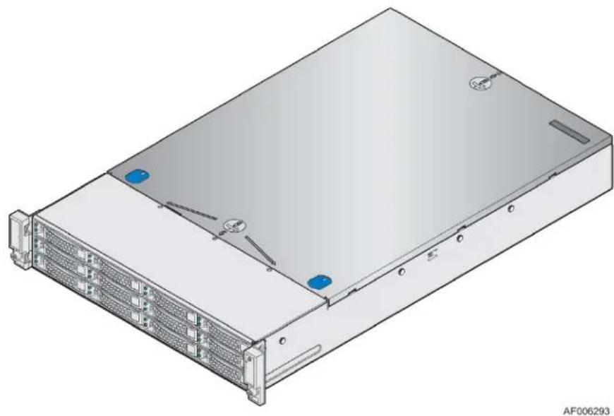
The Intel ^® Storage System JBOD2312S3SP offers the flexibility of adding additional storage to an existing server system with support for 12Gb/s SAS or SATA hard disk drives or SSDs, redundant fan power and power options, and SES communication with the server to monitor the health of the JBOD subsystems.
This chapter provides a high-level overview of the detail for each major system components and features provided in the following sections.
natural_image
3D rendering of a server rack unit with multiple drive bays and mounting holes (no text or symbols visible)Figure 1. 12 x 3.5" Drive JBOD2000S3 Product Drawing
2.1 Chassis Dimensions
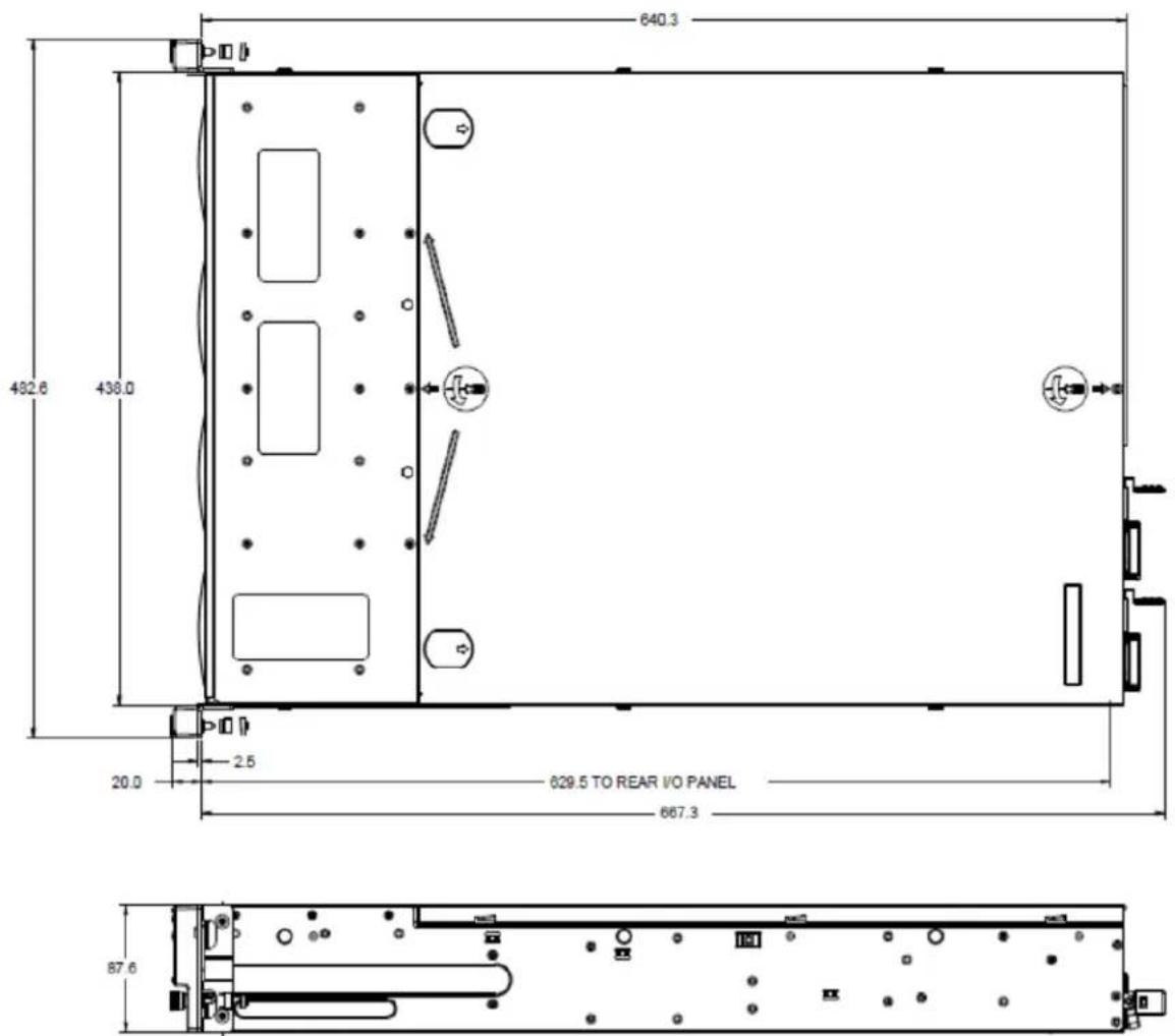
Figure 2. Chassis Dimensions
2.2 System Level Environmental Limits
The following table defines the system level operating and non-operating environmental limits.
Table 1. System Environmental Limits Summary
| Parameter | Limits | |
| Temperature | Operating | ASHRAE Class A2 – Continuous Operation. 10°C to 35°C ^11 (50°F to 95°F) with the maximum rate of change not to exceed 10°C per hour. |
| ASHRAE Class A3 – Includes operation up to 40°C for up to 900 hrs per year. | ||
| ASHRAE Class A4 – Includes operation up to 45°C for up to 90 hrs per year. | ||
| Shipping | -40°C to 70°C (-40°F to 158°F) | |
| Altitude | Operating | Support operation up to 3050m with ASHRAE class deratings. |
| Humidity Shipping | 50% to 90%, non-condensing with a maximum wet bulb of 28°C (at temperatures from 25°C to 35°C) | |
| Shock | Operating | Half sine, 2g, 11 mSec |
| Unpackaged | Trapezoidal, 25g, velocity change is based on packaged weight | |
| Packaged | Product Weight: ≥ 40 to < 80Non-palletized Free Fall Height = 18 inchesPalletized (single product) Free Fall Height = NA | |
| Vibration | Unpackaged | 5 Hz to 500 Hz 2.20 g RMS random |
| Packaged | 5 Hz to 500 Hz 1.09 g RMS random | |
| AC-DC | Voltage | 90 V AC to 132 V AC and 180 V AC to 264 V AC |
| Frequency | 47 Hz to 63 Hz | |
| Source Interrupt | No loss of data for power line drop-out of 12 mSec | |
| Surge Non-operating and operating | Unidirectional | |
| Line to earth Only | AC Leads 2.0 kVI/O Leads 1.0 kVDC Leads 0.5 kV | |
| ESD | Air Discharged | 12.0 kV |
| Contact Discharge | 8.0 kV | |
| Acoustics Sound Power Measured | Power in Watts | <300 W ≥300 W ≥600 W ≥1000 W |
| Servers/Rack Mount BA | 7.0 7.0 7.0 7.0 | |
System 460W Redundant Power Supplies (CRPS) operate in spread-core flow conditions (positive pressure to the power supply's inlet) and incorporate a 40mm fan for its own thermal management. To ensure PS thermal protection under all operating conditions the fan speed control has a closed loop algorithm based on both the critical component temperature and the ambient temperature (inlet temperature). The PS over Temperature Protection (OTP) protects against over temperature conditions created by the loss of fan cooling or excessive ambient temperature. In an OTP condition the PS will shut down and restore power
when the temperature drops to within specified limits. The OTP trip level for inlet temperature is 65^ C with a minimum of 4^ C margin to prevent on and off oscillation.
Disclaimer Note: Intel ensures the unpackaged JBOD system meets the shock requirement mentioned above through its own chassis development and system configuration. It is the responsibility of the system integrator to determine the proper shock level of the JBOD system if the system integrator chooses a different system configuration or different chassis. Intel Corporation cannot be held responsible, if components fail or the system boards do not operate correctly when used outside any of its published operating or non-operating limits.
2.3 System Features and Options Overview
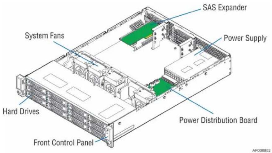
Figure 3. System Components Overview
2.3.1 Hot Swap Hard Drive Bay
natural_image
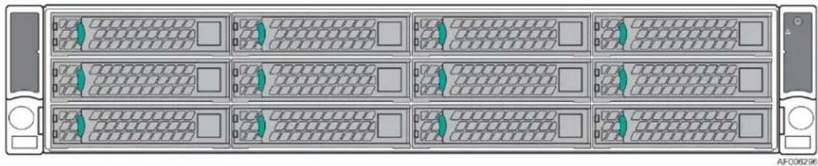
Front view of a rack-mounted server unit with multiple drive bays and ventilation slots (no text or symbols visible)Figure 4. 12 x 3.5" Drive JBOD2000S3SP Front View
2.3.2 Front Control Panel
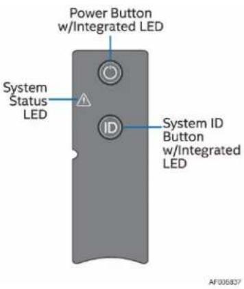
Figure 5. Front Panel Options
The Power Button toggles the system power on and off. Pressing this button sends a signal to the integrated PDB board, which either powers on or powers off the system. The integrated LED is a single-color (Green) indicator that supports different states as defined in the following table.
Table 2. Power LED Functional States
| State | Power Mode | LED | Description |
| Power-off | Non-ACPI | Off | System power is off. |
| Power-on | Non-ACPI | On | System power is on. |
The ID button has no function in this system.
The System Status LED is a bi-color (Green/Amber) indicator that shows the current health of the JBOD system. The System Status LED states are driven by the platform management subsystem. The following table provides a description of each supported LED state.
Table 3. System Status LED State Definitions
| Color | State | Criticality | Description |
| Off | System is not operating | Not ready | The system is powered off (AC and/or DC). |
| Green | Solid on | Ok | Indicates that the system status is “healthy”. The system is not exhibiting any errors. AC power is present and has been powered on. |
| Amber | Solid on | Warning Threshold Alert Event Encountered | P12V has exceeded the warning threshold.P5V has exceeded the warning threshold.P3.3V has exceeded the warning threshold.One of the power supply modules is in a degraded state (No AC or failed).Temperature has exceeded the warning threshold. Event has been detected. |
| Amber | Blinking | Critical Threshold Alert Event Encountered | P12V has exceeded the critical threshold.P5V has exceeded the critical threshold.P3.3V has exceeded the critical threshold.A fan failure has been detected. |
2.3.3 Back Panel Features
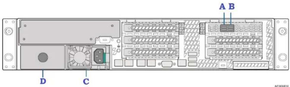
Figure 6. JBOD2312S3SP Back View
| Label | Description |
| A | SFF-8644 receptacle (label: A PRI) |
| B | SFF-8644 receptacle (label: B PRI) |
| C | PSU |
| D | Optional second power module |
3 System Storage and Peripheral Drive Bay Overview
The Intel ^® Storage System JBOD2000S3SP product supports 12 Hot-swap 3.5" hard disk drives.
3.1 3.5" Hard Disk Drive Support
The server is available as a 3.5" hard disk configuration of 12 drives as illustrated below.

Figure 7. 3.5" Hard Drive Bay – 12-Drive Configuration
The drive bay can support either SATA or SAS hard disk drives. Mixing of drive types within the hard drive bay is not supported. Hard disk drive type is dependent on the type of host bus controller used, SATA only or SAS. Each 3.5" hard disk drive is mounted to a drive tray, allowing for hot-swap extraction and insertion. Drive trays have a latching mechanism that is used to extract and insert the drives from the chassis, and lock the tray in place.
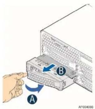
Figure 8. 3.5" Drive Tray Assembly
Light pipes integrated into the drive tray assembly direct the light emitted from Amber drive status and Green activity LEDs located next to each drive connector on the backplane, to the drive tray faceplate, making them visible from the front of the system.

Figure 9. Status and Activity LED on 3.5" Drive Tray
Table 4. Status LED Status
| Amber | Off | No access and no fault. |
| Solid on | Hard drive fault has occurred. | |
| Blink | RAID rebuild in progress (1 Hz);Identify (2 Hz). (Dependent on which RAID controller is used and attached to the JBOD) |
Table 5. Activity LED Status
| Green | Condition | Drive Type | Behavior |
| Power on with no drive activity | SAS | LED stays on. | |
| SATA | LED stays off. | ||
| Power on with drive activity | SAS | LED blinks off when processing a command. | |
| SATA | LED blinks on when processing a command. | ||
| Power on and drive spun down | SAS | LED stays off. | |
| SATA | LED stays off. | ||
| Power on and drive spinning up | SAS | LED blinks. | |
| SATA | LED stays off. |
3.2 3.5" Drive Hot-Swap Backplane Overview
Systems with 12-drive configurations have their own unique backplane. The backplanes mount to the back of the drive bay assembly.
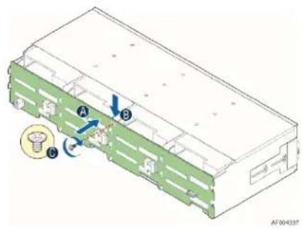
Figure 10.3.5" Hot-Swap Backplane and Drive Bay Assembly
There are 12 hard disk drive interface connectors mounted on the front side of each backplane, each providing both power and I/O signals to the attached hard disk drives.
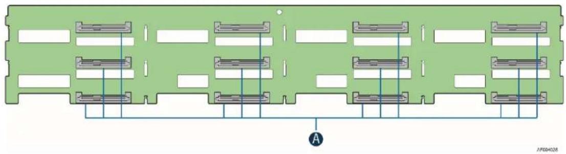
natural_image
Green circuit board diagram with multiple parallel components and labeled connection points (no text or symbols beyond basic layout)Figure 11. SFF-8482 Connector on 3.5" HSBP
On the back side of each backplane, there are several connectors, each of which is identified in the following illustration.
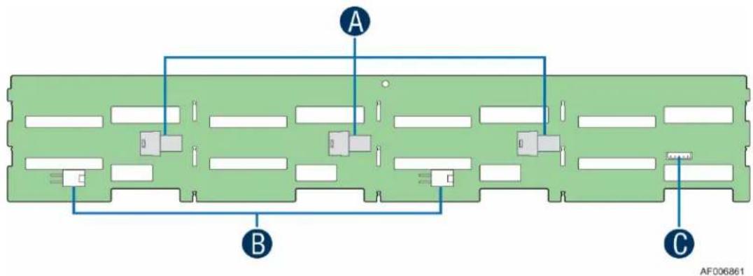
Figure 12. Components on 3.5" HSBP
| Label | Description |
| A | 4-port mini-SAS HD SFF8643 connectors |
| B | Power connectors |
| C | SMBus connector (not used) |
A – 4-port Mini-SAS HD SFF8643 Connectors – The backplane includes two or three multi-port mini-SAS cable connectors, each providing SGPIO and I/O signals for four SAS/SATA hard drives on the backplane. Cables can be routed from matching connectors on the Expander card. Each mini-SAS HD connector includes a silk-screen identifying which drives the connector supports: Drives 0-3, Drives 4-7, and Drives 8-11.
B – Power Harness Connector – The backplane includes a 2x2 connector supplying power to the backplane. Power is routed to the backplane via a power cable harness from the power distribution board (PDB).
3.2.1 Cypress\* CY8C22545 Enclosure Management Controller
The backplanes support enclosure management using a Cypress* CY8C22545 Programmable System-on-Chip (PSoC*) device. The CY8C22545 drives the hard drive activity/fault LED, hard drive present signal, and controls hard drive power-up during system power-on.
4 Power Subsystem
This section provides a high-level overview of the power management features and specification data for the power supply options available for the Intel ^® Storage System JBOD2312S3SP. Specification variations are identified for each supported power supply.
Although the Intel ^® Storage System JBOD2000S3SP ships with only one power supply, a second one can be installed and have up to two power supply modules installed, supporting the following power supply configurations: 1+0 (single power supply), 1+1 Redundant Power, and 2+0 Combined Power non-redundant (Although this system cannot be loaded high enough to hit this mode). The 1+1 redundant power and 2+0 combined power configurations are automatically configured depending on the total power draw of the system. If the total system power draw exceeds the power capacity of a single power supply module, then power from the second power supply module will be utilized. If this occurs, power redundancy is lost. In a 2+0 power configuration, total power available may be less than twice the rated power of the installed power supply modules due to the amount of heat produced with both supplies providing peak power. If system thermals exceed programmed limits, platform management will attempt to keep the system operational. Thermal support is open loop based on ambient temp sensor on the front panel.
The only power supply option validated for the Intel Storage System JBOD2312S3SP is the 460W AC PS. The 750 W AC PS will fit and operate, but will not be validated in the JBOD or plan of record.
NOTE: The power cord is not included with the spare power supply and must be ordered separately. Please refer to the Intel® Storage System JBOD2000S3 Product Family Configuration Guide for ordering information in support.intel.com
The power supplies are modular, allowing for tool-less insertion and extraction from a bay in the back of the chassis. When inserted, the card edge connector of the power supply mates blindly to a matching slot connector on the PDB board.
In the event of a power supply failure, redundant 1+1 power supply configurations have support for hot-swap extraction and insertion.
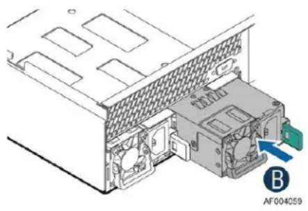
natural_image
Diagram of an internal computer drive showing a power connector and fan structure (no text or symbols)Figure 13. Power Supply Assembly
The AC input is auto-ranging and power factor corrected.
4.1 Power Distribution Board (PDB)
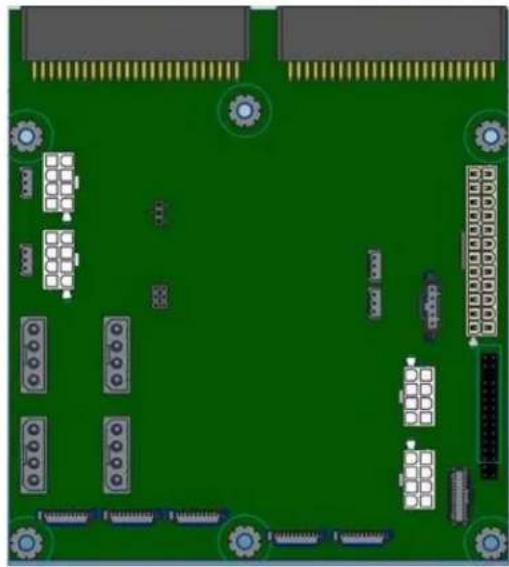
natural_image
Top-down view of a green printed circuit board with various electronic components and connectors (no text or symbols visible)Figure 14. Power Distribution Board (PDB)
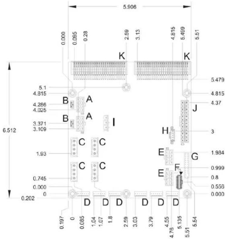
Figure 15. PDB Component Placement
| Label | Description | Label | Description |
| A | HSBP power header | G | 2x12-pin front panel header |
| B | Expander SES-2 header | H | 1x5 aux header |
| C | Expander power header | I | 2x3 Auto Power Jumper |
| D | FAN header | J | 2x12 SSI power connector |
| E | HSBP power header | K | power supply connector |
| F | 2x15-pin storage mini front panel header |
The PDB provides power from the power supply modules to the JBOD components, and provides thermal monitoring and fan control, and includes the following features:
- The PDB connects to the power supply canister through two CRPS card edge connectors.
- Optional 2x12-pin SSI and 1x5-pin SSI power control headers (for potential future use)
- Power for up to two internal 36-port SAS expander cards (RES3FV288) with additional connectors for future use
- Two 2x4-pin 12V power headers and an additional two 2x4-pin 12V power headers for future use, each cable is used to connect power to a single 12x 3.5" HSBP or up to three 8x 2.5" HSBPs.
- Support for hot-swap redundant fan speed control solutions up to four system fans and identification of fan failures at front panel fault LED indicator with communication over SES2 interface to host PC
-
SMB interface for communicating enclosure status through the expander board to the host system external host controller via SES interface. Monitoring capabilities include:
-
Fan tachs.
- 12V voltage out from PSU.
- Temperature sensor on front panel.
- Ambient overtemp protection: Reported to host system and fan boost only. No shutdown.
- Degraded (PSU, FAN) state reportable to host system and on JBOD status LED.
A 3-pin jumper (J2C1) allows setting the Auto Power Enable/Disable setting. The auto power-on jumper setting determines whether the JBOD power-on status will resume automatically if system power is removed and then reapplied. When Auto-Power-On is enabled, the JBOD will power on automatically with application of AC power. When Auto-Power-On is disabled, the JBOD is powered on using the Front Panel push-button switch. The jumper options are described in the table below.
Table 6: Auto Power on Jumper Options
| Jumper Status | Auto Power-on Status | System Behavior after a system power interruption |
| No Jumper | JBOD Auto-Power-On enabled | JBOD Auto-Powers-On when power is applied to the power supply |
| Jumper pins 1 + 2 | JBOD Auto-Power-On disabled | JBOD powers on from front panel push-button only when power is applied to the power supply |
| Jumper pins 2 + 3 | JBOD Auto-Power-On enabled | JBOD Auto-Powers-On when power is applied to the power supply |
The ADT7476 thermal controller on the PDB can measure and control the speed of up to four fans. The controller provides acoustic enhancements to ensure the fans run at the lowest possible speed for the given temperature. The controller interfaces with two remote temp sensors and a local temp sensor built into the chip.
The thermal controller on the PDB is programmed using the SAS expander that comes with the Intel ^® Storage System JBOD2312S3SP. The SAS expander in the Intel ^® Storage System JBOD2000S3SP uses firmware that programs the thermal controller when the system is turned on. If the SAS expander is not plugged into the PDB using the I ^2 C cable, the fans will run at 100% and the thermal controller will not be programmed correctly.
The cable must be connected to the PC port B (Port C will not program the PDB) on the expander board and then either of the I²C connectors on the PDB before the system is turned on.
If the fan runs at 100% at room temperature, there is an issue with the SMBUS connection, the SAS expander is not getting power, or the incorrect firmware is on the expander.
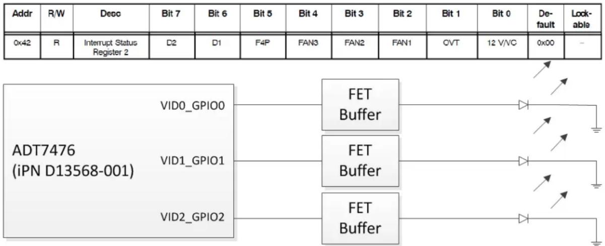
When a fan fails in the Intel ^® Storage System JBOD2312S3SP, an interrupt register bit is set in the ADT7476 Thermal Controller that signals the fan fault (register shown below). The PMC expander chip on the SAS expander monitors this register, and when a fan fault bit is set in the interrupt register, this information is sent to the host system through SES. The ADT7476 controller also sends a signal out of its GPIOs to light the LED on the failed fan's hot-swap housing which makes replacing/diagnosing the failed fan much easier.
Interrupt Register 2 for ADT7476 (Bits 2, 3, and 4 used for fan faults):
flowchart
graph TD
    A["Addr"] --> B["R/W"]
    B --> C["Deco"]
    C --> D["Bit 7"]
    D --> E["Bit 6"]
    E --> F["Bit 5"]
    F --> G["Bit 4"]
    G --> H["Bit 3"]
    H --> I["Bit 2"]
    I --> J["Bit 1"]
    J --> K["Bit 0"]
    K --> L["Default"]
    L --> M["Lockable"]
    N["0x42"] --> O["R"]
    O --> P["Interrupt Status Register 2"]
    P --> Q["D2"]
    Q --> R["D1"]
    R --> S["F4P"]
    S --> T["FAN3"]
    T --> U["FAN2"]
    U --> V["FAN1"]
    V --> W["CVT"]
    W --> X["12 V/VC"]
    X --> Y["0x00"]
    Y --> Z["-"]
    AA["ADT7476 (iPN D13568-001)"] --> AB["VID0_GPIO0"]
    AA --> AC["VID1_GPIO1"]
    AA --> AD["VID2_GPIO2"]
    AE["FET Buffer"] --> AF["Diode symbol"]
    AE --> AG["Diode symbol"]
    AE --> AH["Diode symbol"]
    AE --> AI["Diode symbol"]
    AE --> AJ["Diode symbol"]
    AE --> AK["Diode symbol"]
    AE --> AL["Diode symbol"]
    AE --> AM["Diode symbol"]
    AE --> AN["Diode symbol"]
    AE --> AO["Diode symbol"]
    AE --> AP["Diode symbol"]
Figure 16. Fan Fault LED Block Diagram
4.2 Mechanical Overview
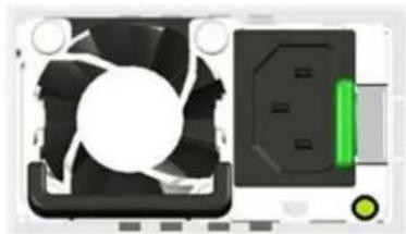
The physical size of the power supply enclosure is 39/40mm x 74mm x 185mm. The power supply contains a single 40mm fan. The power supply has a card edge output that interfaces with a 2x25 card edge connector in the system. The AC plugs directly into the external face of the power supply.
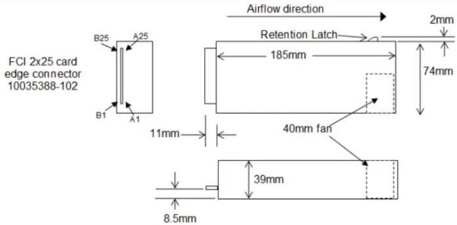
Figure 17. Power Supply Module Mechanical Drawing
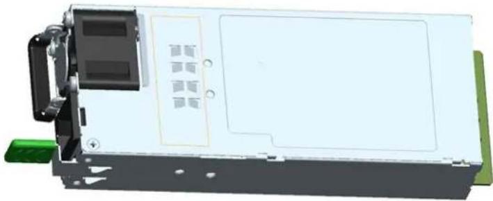
natural_image
3D rendering of a white electronic device with black components and a green connector (no visible text or symbols)Figure 18. Power Supply Module
natural_image
Illustration of a computer CPU fan and its rear panel with a green indicator light (no text or symbols)Figure 19. AC Power Supply – Connector View
4.3 Power Connectors
4.3.1 Power Supply Module Card Edge Connector
Each power supply module has a single 2x25 card edge output connection that plugs directly into a matching slot connector on the server board. The connector provides both power and communication signals to the server board. The following table defines the connector pin-out.
Table 7. Power Supply Module Output Power Connector Pin-out
| Pin | Name | Pin | Name |
| A1 | GND | B1 | GND |
| A2 | GND | B2 | GND |
| A3 | GND | B3 | GND |
| A4 | GND | B4 | GND |
| A5 | GND | B5 | GND |
| A6 | GND | B6 | GND |
| A7 | GND | B7 | GND |
| A8 | GND | B8 | GND |
| A9 | GND | B9 | GND |
| A10 | +12V | B10 | +12V |
| A11 | +12V | B11 | +12V |
| A12 | +12V | B12 | +12V |
| A13 | +12V | B13 | +12V |
| A14 | +12V | B14 | +12V |
| A15 | +12V | B15 | +12V |
| A16 | +12V | B16 | +12V |
| A17 | +12V | B17 | +12V |
| A18 | +12V | B18 | +12V |
| A19 | PMBus SDA | B19 | A0 (SMBus address) |
| A20 | PMBus SCL | B20 | A1 (SMBus address) |
| A21 | PSON | B21 | 12V stby |
| A22 | SMBAAlert# | B22 | Cold Redundancy Bus |
| A23 | Return Sense | B23 | 12V Load Share Bus |
| A24 | +12V Remote Sense | B24 | No Connect |
| A25 | PWOK | B25 | Compatibility Check pin* |
The JBOD's PDB provides several connectors to provide power to various system options. The following subsections identify the location, provide the pin-out definition, and provide a brief usage description for each.
4.3.2 Hot-Swap Backplane Power Connector
The JBOD's PDB board includes four white 2x4-pin power connectors, used to provide power to the hot-swap backplanes. On the JBOD PDB, this connector is labeled as "HSBP PWR". The following table provides the pin-out for this connector.
Table 8. Hot-swap Backplane Power Connector Pin-out ("HSBP PWR")
| Pin | Signal Description | Pin | Signal Description |
| 1 | Ground | 5 | P12V_240VA |
| 2 | Ground | 6 | P12V_240VA |
| 3 | Ground | 7 | P12V_240VA |
| 4 | Ground | 8 | P12V_240VA |
4.4 Power Supply Module Efficiency
The following table provides the required minimum efficiency level at various loading conditions. These are provided at four different load levels: 100%, 50%, 20%, and 10%. Efficiency is tested over an AC input voltage range of 115 VAC to 220 VAC.
Table 9. 460 Watt Power Supply Efficiency
| Loading | 100% of Maximum | 50% of Maximum | 20% of Maximum | 10% of Maximum |
| Minimum efficiency | 88% | 92% | 88% | 80% |
4.5 AC Power Cord Specification Requirements
The AC power cord used meets the specification requirements listed in the following table.
Table 10. AC Power Cord Specifications
| Cable Type | SJT |
| Wire Size | 16 AWG |
| Temperature Rating | 105°C |
| Amperage Rating | 13 A |
| Voltage Rating | 125 V |
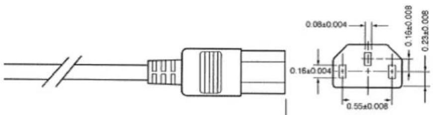
Figure 20. AC Power Cord
4.6 AC Input Specifications
4.6.1 Power Factor
The power supply meets the power factor requirements stated in the Energy Star Program Requirements for Computer Servers. These requirements are stated below.
Table 11. Power Factor
| Output Power | 10% Load | 20% Load | 50% Load | 100% Load |
| Power factor | >0.65 | >0.80 | >0.90 | >0.95 |
Note: Tested at 230VAC, 50Hz and 60Hz and 115VAC, 60Hz
4.6.2 AC Input Voltage Specification
The power supply operates within all specified limits over the following input voltage range. Harmonic distortion of up to 10% of the rated line voltage does not cause the power supply to go out of specified limits. Application of an input voltage below 85VAC does not cause damage to the power supply, including a blown fuse.
Table 12. AC Input Voltage Range
| Parameter | Min | Rated | Vmax | Start-up VAC | Power-off VAC |
| Voltage (110) | 90 Vrms | 100-127 Vrms | 140 Vrms | 85VAC +/-4VAC | 70VAC +/-5VAC |
| Voltage (220) | 180 Vrms | 200-240 Vrms | 264 Vrms | ||
| Frequency | 47 Hz | 50/60 Hz | 63 Hz |
- The maximum input current at low input voltage range is measured at 90VAC, at max load.
- The maximum input current at high input voltage range is measured at 180VAC, at max load.
- This requirement is not to be used for determining agency input current markings.
4.6.3 AC Line Isolation Requirements
The power supply meets all safety agency requirements for dielectric strength. Transformers' isolation between primary and secondary windings complies with the 3000VAC (4242VDC) dielectric strength criteria. If the working voltage between primary and secondary dictates a higher dielectric strength test voltage, the highest test voltage will be used. In addition the insulation system complies with reinforced insulation per safety standard IEC 950. Separation between the primary and secondary circuits, and primary to ground circuits, complies with the IEC 950 spacing requirements.
4.6.4 AC Line Dropout/Holdup
An AC line dropout is defined to be when the AC input drops to OVAC at any phase of the AC line for any length of time. During an AC dropout the power supply meets dynamic voltage regulation requirements. An AC line dropout of any duration does not cause tripping of control signals or protection circuits. If the AC dropout lasts longer than the holdup time, the power supply will recover and meet all turn-on requirements. The power supply meets the AC dropout requirement over rated AC voltages and frequencies. A dropout of the AC line for any duration does not cause damage to the power supply.
Table 13. AC Line Dropout/Holdup
| Loading | Holdup Time |
| 70% | 12msec |
4.6.4.1 AC Line 12VSB Holdup
The 12VSB output voltage stays in regulation under its full load (static or dynamic) during an AC dropout of 70ms min (=12VSB holdup time) whether the power supply is in ON or OFF state (PSON asserted or de-asserted).
4.6.5 AC Line Fuse
The power supply has one line fused in the single line fuse on the line (Hot) wire of the AC input. The line fusing is acceptable for all safety agency requirements. The input fuse is a slow blow type. The AC inrush current does not cause the AC line fuse to blow under any conditions. All protection circuits in the power supply will not cause the AC fuse to blow unless a component in the power supply has failed. This includes DC output load short conditions.
4.6.6 AC Inrush
The AC line inrush current does not exceed 55A peak, for up to one-quarter of the AC cycle, after which, the input current is no more than the specified maximum input current. The peak inrush current is less than the ratings of its critical components (including input fuse, bulk rectifiers, and surge limiting device).
The power supply meets the inrush requirements for any rated AC voltage, during turn-on at any phase of AC voltage, during a single cycle AC dropout condition as well as upon recovery after AC dropout of any duration, and over the specified temperature range ( T_op ).
4.6.7 AC Line Transient Specification
The AC line transient conditions are defined as sag and surge conditions. Sag conditions are also commonly referred to as "brownout"; these conditions are defined as the conditions when the AC line voltage drops below nominal voltage. Surge conditions are defined as the conditions when the AC line voltage rises above nominal voltage.
The power supply meets the requirements under the following AC line sag and surge conditions.
Table 14. AC Line Sag Transient Performance
| AC Line Sag (10sec interval between each sagging) | ||||
| Duration | Sag | Operating AC Voltage | Line Frequency | Performance Criteria |
| 0 to 1/2 AC cycle | 95% | Nominal AC Voltage ranges | 50/60 Hz | No loss of function or performance |
| >1 AC cycle | >30% | Nominal AC Voltage ranges | 50/60 Hz | Loss of function acceptable, self recoverable |
Table 15. AC Line Surge Transient Performance
| AC Line Surge | ||||
| Duration | Surge | Operating AC Voltage | Line Frequency | Performance Criteria |
| Continuous | 10% | Nominal AC Voltages | 50/60 Hz | No loss of function or performance |
| 0 to 1⁄2 AC cycle | 30% | Mid-point of nominal AC Voltages | 50/60 Hz | No loss of function or performance |
4.6.8 Susceptibility Requirements
The power supply meets the following electrical immunity requirements when connected to a cage with an external EMI filter that meets the criteria defined in the SSI document EPS Power Supply Specification. For further information on Intel standards, request a copy of the Intel Environmental Standards Handbook.
Table 16. Performance Criteria
| Level | Description |
| A | The apparatus continues to operate as intended. No degradation of performance. |
| B | The apparatus continues to operate as intended. No degradation of performance beyond spec limits. |
| C | Temporary loss of function is allowed provided that the function is self-recoverable or can be restored by the operation of the controls. |
4.6.9 Electrostatic Discharge Susceptibility
The power supply complies with the limits defined in EN 55024: 1998/A1: 2001/A2: 2003 using the IEC 61000-4-2: Edition 1.2: 2001-04 test standard and performance criteria B defined in Annex B of CISPR 24.
4.6.10 Fast Transient/Burst
The power supply complies with the limits defined in EN 55024: 1998/A1: 2001/A2: 2003 using the IEC 61000-4-4: Second edition: 2004-07 test standard and performance criteria B defined in Annex B of CISPR 24.
4.6.11 Radiated Immunity
The power supply complies with the limits defined in EN 55024: 1998/A1: 2001/A2: 2003 using the IEC 61000-4-3: Edition 2.1: 2002-09 test standard and performance criteria A defined in Annex B of CISPR 24.
4.6.12 Surge Immunity
The power supply is tested with the system for immunity to AC unidirectional wave, 2kV line to ground and 1kV line to line, per EN 55024: 1998/A1: 2001/A2: 2003, EN 61000-4-5: Edition 1.1:2001-04.
The pass criteria include: no unsafe operation is allowed under any condition; all power supply output voltage levels to stay within proper spec levels; no change in operating state or loss of data during and after the test profile; no component damage under any condition.
The power supply complies with the limits defined in EN 55024: 1998/A1: 2001/A2: 2003 using the IEC 61000-4-5: Edition 1.1:2001-04 test standard and performance criteria B defined in Annex B of CISPR 24.
4.6.13 Voltage Interruptions
The power supply complies with the limits defined in EN 55024: 1998/A1: 2001/A2: 2003 using the IEC 61000-4-11: Second Edition: 2004-03 test standard and performance criteria C defined in Annex B of CISPR 24.
4.6.14 Protection Circuits
The protection circuits inside the power supply cause only the power supply's main outputs to shut down. If the power supply latches off due to a protection circuit tripping, an AC cycle OFF for 15 seconds and a PSON# cycle HIGH for one second reset the power supply.
4.6.15 Over Current Protection (OCP)
The power supply has a current limit to prevent the outputs from exceeding the values shown in the table below. If the current limit is exceeded, the power supply will shut down and latch off. The latch will be cleared by toggling the PSON# signal or by an AC power interruption. The power supply will not be damaged from repeated power cycling in this condition. 12VSB will be auto-recovered after removing the OCP limit.
Table 17. 460 Watt Power Supply Over Current Protection
| Output Voltage | Input Voltage Range | Over Current Limit |
| +12V | 90–264VAC | 47A min; 55A max |
| 12VSB | 90–264VAC | 2A min; 2.5A max |
4.6.16 Over Voltage Protection (OVP)
The power supply over voltage protection is locally sensed. The power supply will shut down and latch off after an over voltage condition occurs. This latch will be cleared by toggling the PSON# signal or by an AC power interruption. The values are measured at the output of the power supply's connectors. The voltage never exceeds the maximum levels when measured at the power connectors of the power supply connector during any single point of fail. The voltage never trips any lower than the minimum levels when measured at the power connector. 12VSB will be auto-recovered after removing the OVP limit.
Table 18. Over Voltage Protection (OVP) Limits
| Output Voltage | Min (V) | Max (V) |
| +12V | 13.3 | 14.5 |
| 12VSB | 13.3 | 14.5 |
4.6.17 Over Temperature Protection (OTP)
The power supply is protected against over temperature conditions caused by loss of fan cooling or excessive ambient temperature. In an OTP condition the PSU will shut down. When the power supply temperature drops to within specified limits, the power supply will restore power automatically, while the 12VSB remains always on. The OTP circuit has a built-in margin so that the power supply will not oscillate on and off due to temperature recovering conditions. The OTP trip level has a minimum of 4°C of ambient temperature margin.
4.7 Power Supply Status LED
There is a single bi-color LED to indicate power supply status. The LED operation is defined in the following table.
Table 19. LED Indicators
| Power Supply Condition | LED State |
| Output ON and OK | Green |
| No AC power to all power supplies | Off |
| AC present / Only 12VSB on (PS off) | 1 Hz Blink Green |
| AC cord unplugged or AC power lost, with a second power supply in parallel still with AC input power | Amber |
| Power supply warning events where the power supply continues to operate; high temp, high power, high current, slow fan | 1 Hz Blink Amber |
| Power supply critical events causing a shutdown; failure, OCP, OVP, fan fail | Amber |
5 Thermal Management
The Intel ^® Storage System JBOD2312S3SP is designed to operate at external ambient temperatures of between 10°C and 35°C with limited excursion-based operation up to 45°C and limited performance impact. Working with integrated platform management, several features within the system are designed to move air in a front-to-back direction, through the system and over critical components to prevent them from overheating and allow the system to operate with best performance.
The installation and functionality of several JBOD components are used to maintain system thermals. They include up to three managed 60-mm system fans and one integrated 40-mm fan for each installed power supply module. Hard drive carriers can be populated with a hard drive or supplied drive blank.
5.1 Thermal Operation and Configuration Requirements
To keep the system operating within supported maximum thermal limits, the system must meet the following operating and configuration guidelines:
- The system operating ambient is designed for sustained operation up to 35°C (ASHRAE Class A2) with short-term excursion-based operation up to 45°C (ASHRAE Class A4).
- The system can operate up to 40°C (ASHRAE Class A3) for up to 900 hours per year.
- The system can operate up to 45°C (ASHRAE Class A4) for up to 90 hours per year.
- System performance may be impacted when operating within the extended operating temperature range.
-
There is no long-term system reliability impact when operating at the extended temperature range within the approved limits.
-
All hard drive bays must be populated. Hard drive carriers can be populated with a hard drive or supplied drive blank.
- In single power supply configurations, the second power supply bay must have the supplied filler blank installed at all times.
- The system must be configured with dual power supplies for the system to support fan redundancy.
- The system top cover must be installed at all times when the system is in operation. The only exception to this requirement is to hot replace a failed system fan, in which case the top cover can be removed for no more than three minutes at a time.
5.2 Thermal Management Overview
In order to maintain the necessary airflow within the system, all of the previously listed components and top cover need to be properly installed. For best system performance, the external ambient temperature should remain below 35^ C and all system fans should be operational. The system is designed for fan redundancy when the system is configured with two power supplies.
5.3 Thermal Sensor Input for Fan Speed Control
The power distribution board uses various sensors as inputs to fan speed control. Some of the sensors are actual physical sensors and some are virtual sensors derived from calculations. The Front Panel Temperature Sensor is used as an input to fan speed control.
5.4 System Fans
Four 60x38-mm fans and an embedded fan for each installed power supply, provide the primary airflow for the system. The system is designed for fan redundancy when configured with two power supply modules. If a single fan fails (system fan or power supply fan), platform management will adjust the airflow of the remaining fans and manage other platform features to maintain system thermals. Fan redundancy is lost if more than one fan is in a failed state.
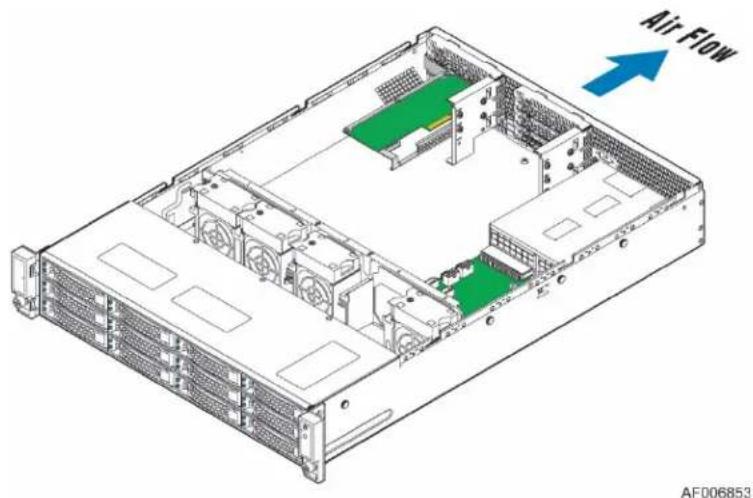
Figure 21. System Fan Identification
The system fan assembly is designed for ease of use and supports several features:
■ Each fan is hot-swappable.
- Each fan is designed for tool-less insertion and extraction from the fan assembly. For instructions on installing or removing a fan module, see the Intel' JBOD2000S3SP Service Guide.
- Fan speed for each fan is controlled by integrated platform management controlled by the PDB. When system thermals fluctuate high and low, the PDB firmware will increase or decrease the speeds of specific fans within the fan assembly to regulate system thermals.
- Each fan has a tachometer signal that allows the PDB to monitor its status.
- On top of each fan is an integrated fan fault LED, which will turn on when a fan failure occurs.
- Each fan has a 10-pin wire harness that connects to a matching connector on the PDB.
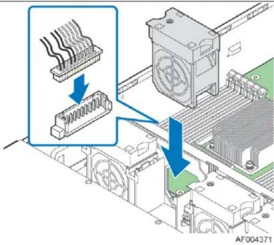
Figure 22. System Fan Assembly
Table 20. System Fan Connector Pin-out
| SYS_FAN 1 | SYS_FAN 2 | SYS_FAN 3 | |||
| Pin# | Signal Description | Pin# | Signal Description | Pin# | Signal Description |
| 1 | FAN_TACH1_IN | 1 | FAN_TACH3_IN | 1 | FAN_TACH5_IN |
| 2 | FAN_BMC_PWM0_R_BUF | 2 | FAN_BMC_PWM1_R_BUF | 2 | FAN_BMC_PWM2_R_BUF |
| 3 | P12V_FAN | 3 | P12V_FAN | 3 | P12V_FAN |
| 4 | P12V_FAN | 4 | P12V_FAN | 4 | P12V_FAN |
| 5 | FAN_TACH0_IN | 5 | FAN_TACH2_IN | 5 | FAN_TACH4_IN |
| 6 | GROUND | 6 | GROUND | 6 | GROUND |
| 7 | GROUND | 7 | GROUND | 7 | GROUND |
| 8 | FAN_SYS0_PRSNT_N | 8 | FAN_SYS1_PRSNT_N | 8 | FAN_SYS2_PRSNT_N |
| 9 | LED_FAN_FAULT0_R | 9 | LED_FAN_FAULT1_R | 9 | LED_FAN_FAULT2_R |
| 10 | LED_FANO | 10 | LED_FAN1 | 10 | LED_FAN2 |
5.5 Fan Speed Control
Fan speed control for this system is driven primarily by the front panel temp sensor which is representative of system ambient Temperature (Tsa). Fan speed override is driven by thermal sensors located on the expander board.
The thermal solution in this 2U system utilizes four 60mm x 38mm fans.
Table 21: PWM Settings
| Altitude | Up to 3000M | |
| Tsa[C] | PWM | Fan Failed |
| 11C | 45% | 100% |
| 25C | 45% | |
| 28C | 50% | |
| 30C | 55% | |
| 33C | 60% | |
| 35C | 65% | |
| 40C | 80% | |
| 43C | 100% | |
The FSC algorithm includes a 4 data point rolling average to assert the threshold value and 2°C hysteresis to prevent fan speed oscillations.
Table 22: Temperature Notification Thresholds
| Limit | Sensor1Front Panel | Sensor 3 – Expander Processor Internal |
| High Critical | 56C | 125 |
| High Warning | 54C | 120 |
| Low Warning | 27C | 25 |
| Low Critical | 22C | 20 |
- Actual sensor temperature is -20^ - SES protocol uses a 20^ offset.
- Front Panel Sensor 1 has a 2^ offset due to self-heating.
Fan control overrides:
- If Temperature Sensor 3 exceeds its High Warning threshold -> set Fans to 80%.
- If Temperature Sensor 3 exceeds its High Critical threshold -> set Fans to 100%.
5.6 Power Supply Module Fan
Each installed power supply module includes one embedded (non-removable) 40-mm fan. It is responsible for airflow through the power supply module. If this fan fails, the power supply will continue to operate until its internal temperature reaches an upper critical limit. The power supply will be protected against over temperature conditions caused by loss of fan cooling or excessive ambient temperature. In an over-temperature protection condition, the power supply module will shut down.
6 JBOD2000S3SP Internal Connection Overview
The Intel ^® Storage System JBOD2000S3SP contains one or two SAS expander board(s), power distribution board, HSBP, and fans in its chassis. This section provides specification of the SAS expander board and SAS converter, and interconnection between those components.
6.1 Expander Board
The Intel 36-port expander (RES3FV288) is mounted in a retention mechanism at the rear of the chassis that provides access to the external facing SAS ports, and is designed on PMC's 12Gb/s expander technology. The expander has seven SFF8643 mini-SAS HD connectors that connect internally to the backplane and two externally facing SFF8644 connectors. The dual-port backplane of the JBOD contains two 36-port expanders, while the single-port backplane contains one 36-port expander.
Features of the Intel ^* RAID Expander are as follows:
- SAS protocol, described in the Serial Attached SCSI (SAS) Standard, version 3.0
- Serial SCSI Protocol (SSP) to enable communication with other SAS devices
- Serial Tunneling Protocol (STP) support for SATA II through expander interfaces
- Serial Management Protocol (SMP) to share topology management information with expanders
■ Supports SES for enclosure management - Output mini-SAS HD connectors support sideband SGPIO as per SFF-8448 specification
■ Supports both Serial Attached SCSI and Serial ATA device targets - 12Gb/s, 6Gb/s, 3Gb/s, and 1.5 Gb/s data transfer rates
■ SFF-8643 and SFF-8644 mini-SAS HD connectors - Provides a low-latency connection to create and maintain transparent access to each connected SAS/SATA physical drive
- Staggered spin-up
Hot-plug - Native Command Queuing
- Allows multiple initiators to address a single target (in a fail-over configuration)
SAS Expander Major Components:
■ 36-Port 12 Gb/s SAS-3 Expander Chip
- Provides 36 PHYs
■ Any PHYs may be combined into wide port(s)
■ Any PHY can be SAS or SATA attached
- Supports multiple data rates and auto-negotiation between the following:
■ 3 Gb/s, 6.0 Gb/s, and 12.0 Gb/s SAS
■ 1.5 Gb/s, 3 Gb/s, and 6.0 Gb/s SATA
- Supports SSP, STP, and SMP
- Supports the SAS protocol described in the Serial Attached SCSI (SAS) Standard, version 3.0r5
- Provides a low-latency connection router to efficiently create and maintain connections
- Supports T10-Based and Phy-Based Zoning for storage partitioning
- Allows any number of phys to be included in a wide port
- Provides up to 12 I2C interfaces
- Flash ROM – A 128-Mbit Quad SPI flash ROM is used to accommodate expander card firmware.
- Heartbeat LED – A green LED provides a heartbeat with a 1 second blink rate to indicate the expander has booted properly.
All JBOD SKUs use the 36-port SAS expander card. Single-port JBOD2000S3SP SKU has one 36-port SAS expander card.
See the Intel® RAID Expander RES3FV288 User Guide at www.intel.com.
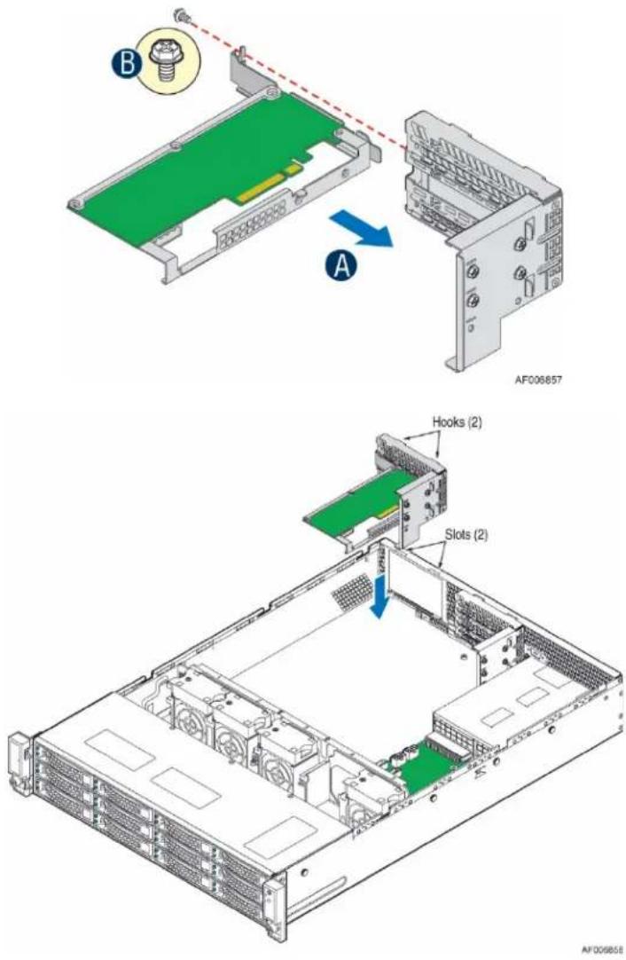
Figure 23. Internal SAS Expander Location
6.1.1 JBOD SAS Expander Port Numbering
Following is a suggestion for the JBOD SAS expander port numbering for internal and external connections.
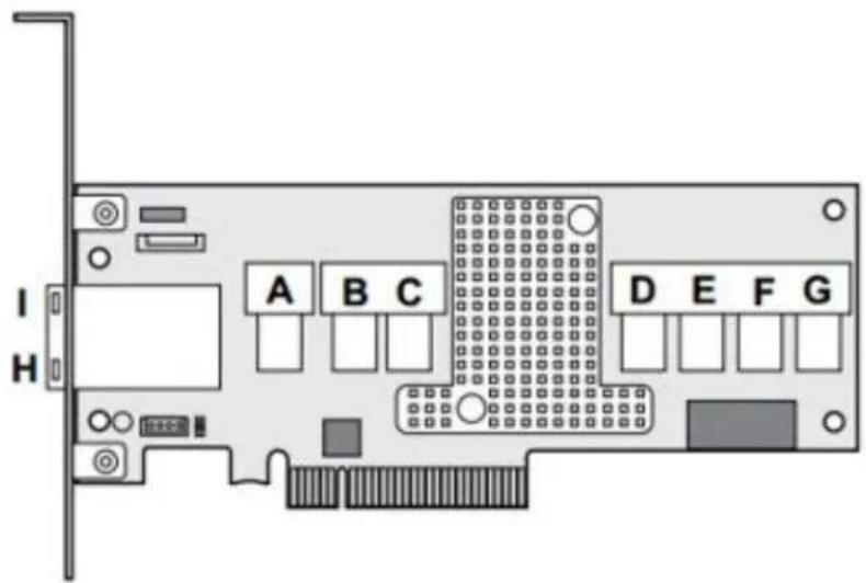
| Connector | Description | Type | Comment |
| A, B, C, D, E | Internal Output connectors (to backplane) | SFF-8643 | A– SAS Output ports (0-3)B – SAS Output ports (4-7)C – SAS Output ports (8-11)D– SAS Output ports (12-15)E – SAS Output ports (16-19) |
| F, G | Internal Input connectors (from RAID controller/HBA) | SFF-8643 | F – SAS Input ports (0-3)G – SAS Input ports (4-7) |
| H, I | External Output connectors (to JBOD) | SFF-8644 | H – SAS Output ports (20-23)I – SAS Output ports (24-27) |
Figure 24: SAS Expander Port Numbering
The Intel ^® RAID Expander RES3FV288 is transparent to users in RAID configurations. Refer to the technical specification or user guide of the RAID controller connected to this expander card to know how to configure a RAID system.
6.1.2 JBOD2312S3SP Interconnection
The Intel ^® Storage System JBOD2312S3SP has a 12x3.5" single-port HSBP, a primary SAS expander, a dual-port SAS interface board, a PDB, a PSU, and four fans in its chassis.
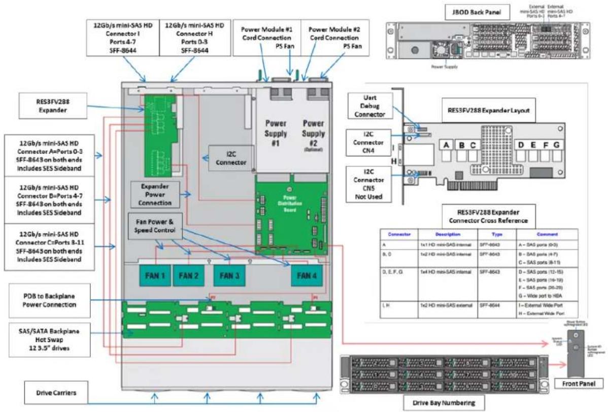
Figure 25. 12x3.5" Single-port JBOD2000S3SP Interconnection Diagram
7 JBOD2000S3SP External SAS Connection Mode Overview
The Intel ^® Storage System JBOD2312S3SP supports connection to many different external SAS HBA and SAS RAID controller solutions, to achieve single JBOD connection, multiple JBODs daisy chain connection, and failover connections. This section provides an overview of the different options available.
7.1 External SAS Controller Support
Our current and future supported controllers are referenced via our JBOD2000S3SP THOL or SCT.
SAS connectivity is via the external SAS connectors (SFF8644); both native SAS HBAs and RAID HBAs are supported.
7.2 External SAS Cable
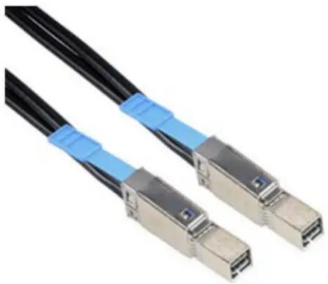
JBOD2000S3SP system uses SFF-8644 mini-SAS receptacle, so SFF-8644 mini-SAS cable is needed when connecting the JBOD2000S3SP to host or cascading to other JBOD2000. The following figure is an illustration of SFF-8644 mini-SAS cable.
natural_image
Close-up of two black fiber optic cables with blue connectors, no text or symbols visibleFigure 26. SFF-8644 mini-SAS Cable
According to SAS 3.0 specification, the length of mini-SAS cable has the following rules:
- The 12Gb/s SAS cables work up to 10 meters with DFE (decision feedback equalization).
- The 12Gb/s SAS cables run at less than 6 meters without DFE.
- The 6Gb/s SAS deployments are limited to cable length of 6 meters.
- The 3Gb/s SAS deployments are limited to cable length 6 meters.
The standard package of JBOD2000S3SP system doesn't contain external cables (you need to order the cable from other vendors). Intel has tested some models of the mini-SAS HD cable (see Appendix A for the list). However, the mini-SAS HD cables that JBOD2000S3SP can support are not limited to that list; users can qualify new cables by themselves.
7.3 Hard Drive Type
JBOD2000S3SP can support 12Gb/s, 6Gb/s, and 3Gb/s SAS hard drives and 3Gb/s and 6Gb/s SATA hard drives. SATA hard drives do not support some configurations, which need to take advantage of the dual-port SAS hard drives, such as dual-domain SAS or failover clustering.
Refer to the Intel server configurator tool to a list of tested hard drives at https://serverconfigurator.intel.com.
7.4 JBOD Cascade
JBOD cascading is also called daisy-chaining, which means connecting multiple JBOD units to constitute deeper storage pool. How many JBOD2000S3SP can be cascaded depends on the property of the SAS HBA or RAID adapter that connects to JBOD2000SP3. However, only two layers of cascaded JBOD2000S3SP system have been fully validated by Intel. Only cascading the same type of JBOD2000S3SP is recommended.
7.5 Single-port JBOD2000S3SP External Connection Mode
The following sections provide the external connection modes supported by the Intel ^® Storage System JBOD2000S3SP single-port backplane SKU.
7.5.1 Single JBOD2000S3SP Connection
Figure 27 below shows the SAS HBA or RAID adapter connecting to one single-port JBOD2000S3SP with one mini-SAS HD cable. The single controller port incorporates four SAS lanes for a total maximum throughput of 4800MB/s with SAS 3.0 technology. In the figure, the “4\” notation indicates a 4-lane bundled path. Either A PRI or B PRI SAS port on JBOD2000S3SP can be connected in this scenario. SATA or SAS hard drives can be supported.
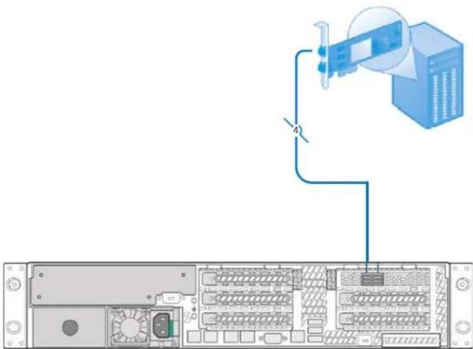
Figure 27. Single JBOD2000S3SP Connection
7.5.2 Two JBOD2000S3SP Cascade
Figure 28 below shows two cascaded single-port JBOD2000S3SP connecting to the SAS HBA or RAID adapter with one mini-SAS cable. The function of SAS port "A PRI" and "B PRI" on JBOD2000S3SP are equivalent. Either "A PRI" or "B PRI" SAS port can be connected to the SAS adapter or cascaded with other JBOD2000S3SP in this scenario. SATA or SAS hard drive can be supported.
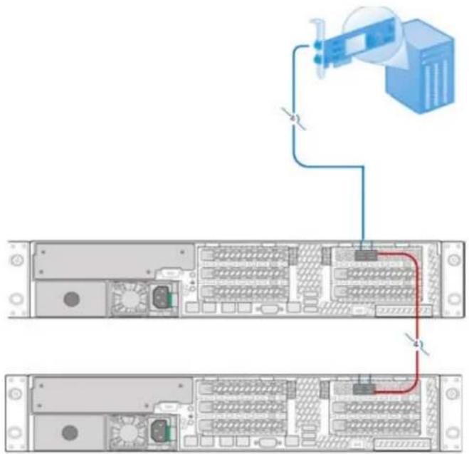
Figure 28. Two Single-port JBOD2000S3SP Cascade
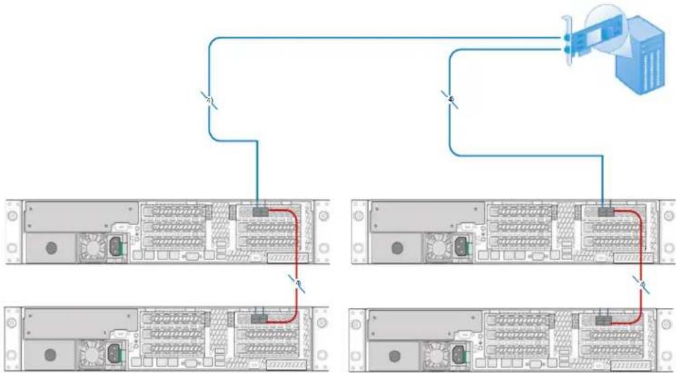
Figure 29 below shows another connection scenario in which the SAS HBA or RAID adapter has two external mini-SAS connectors. Other group of two cascaded single-port JBOD2000S3SP can be connected to the host adapter with one mini-SAS cable. Users can get more storage space with this kind of connection mode.
flowchart
graph TD
    A["Server Rack 1"] -->|Line 1| B["Terminal Server"]
    A -->|Line 2| C["Terminal Server"]
    D["Server Rack 2"] -->|Line 3| E["Terminal Server"]
    D -->|Line 4| F["Terminal Server"]
    G["Terminal Server"] -->|Line 5| H["Terminal Server"]
    style A fill:#f9f,stroke:#333
    style D fill:#f9f,stroke:#333
    style G fill:#f9f,stroke:#333
Figure 29. Two Groups of Cascaded Single-port JBOD2000S3SP
7.5.3 Dual-path Connection
Dual-path means a host has redundant pathways to the storage device. When any part of the data pathway to a SAS domain fails, data transfer will not stop. This is one advantage of dual-path connection. Dual-path implementations cost less than dual-domain SAS implementations but do not provide the full redundancy like a dual-domain SAS solution.
Figure 30 below shows the dual external mini-SAS HD connectors of the SAS HBA or RAID adapter connecting to JBOD2000S3SP with two mini-SAS HD cables. Each single controller port incorporates four SAS lanes for a total maximum throughput of 4800MB/s with SAS 3.0 technology. SATA or SAS hard drive can be supported. The SAS HBA or RAID adapter can handle either mini-SAS cable disconnection and maintain the data transfer between the host and JBOD2000S3SP.
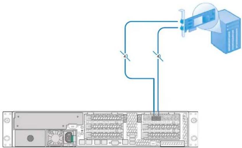
Figure 30. Dual-path Connection
7.5.4 Dual-path with Cascaded JBOD2000S3SP
Dual-path to a single-domain provides tolerance of cable failure. Two single-port JBOD2000S3SP systems are cascaded with a mini-SAS cable between each "B PRI" SAS port, and a controller connects to each "A PRI" SAS port with two mini-SAS HD cables. Any mini-SAS HD cable failure will not stop the data transfer between the host and two JBOD2000S3SP. Both SAS and SATA drives support this configuration.
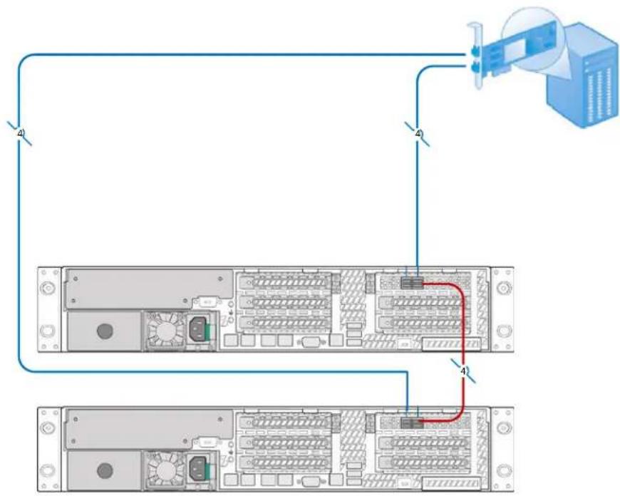
flowchart
graph TD
    A["Server Rack"] -->|4| B["Switch"]
    B -->|4| C["Server Unit"]
    C -->|4| D["Server Rack"]
    D -->|4| E["Switch"]
    E -->|4| F["Server Unit"]
Figure 31. Dual-path with Cascaded JBOD2000S3SP
Appendix A. Qualified External Mini-SAS Cable List
HD MiniSAS external cables are available from a variety of vendors. For reference, the list of external cables below used during Intel testing is provided. Customers should perform their own qualification testing of the cables they select for use.
Table 23: External Cable List
| Vendor | Manufactures Part Number | Description |
| AmphenolCables on Demand | CS-SASMINIHD2-001 | 1m (3.3') External 4x HD Mini-SAS Cable - 4x Mini-SAS HD (SFF-8644) to 4x Mini-SAS HD (SFF-8644) Passive Copper Cable Assembly [30 AWG] - 12 Gbps SAS 3.0 & iPass+TM HD Compliant |
| AmphenolCables on Demand | CS-SASMINIHD2-003 | 3m (9.8') External 4x HD Mini-SAS Cable - 4x Mini-SAS HD (SFF-8644) to 4x Mini-SAS HD (SFF-8644) Passive Copper Cable Assembly [28 AWG] - 12 Gbps SAS 3.0 & iPass+TM HD Compliant |
| Data Storage Cables | C5555-.5M | HD Mini SAS 4X - HD Mini SAS 4X, .5M |
| Data Storage Cables | C5555-6M | HD Mini SAS 4X - HD Mini SAS 4X, 6M |
Appendix B. Reference Documents
Refer to the following documents for additional information:
Intel ^9 Storage System JBOD2312S3SP Service Guide
Intel ^9 High Availability Storage User Guide
Intel ^* RAID Expander RES3FV288 User Guide
- Intel® Storage System JBOD2312S3SP
- Hardware Guide
- Disclaimers
- Table of Contents
- Introduction....1
- Product Family Overview....2
- System Storage and Peripheral Drive Bay Overview....8
- Power Subsystem....11
- Thermal Management 23
- JBOD2000S3SP Internal Connection Overview.... 27
- JBOD2000S3SP External SAS Connection Mode Overview 31
- List of Figures
- List of Tables
- Introduction
- Server Product Use Disclaimer
- Product Errata
- Product Family Overview
- Chassis Dimensions
- System Level Environmental Limits
- System Features and Options Overview
- Hot Swap Hard Drive Bay
- Front Control Panel
- Back Panel Features
- System Storage and Peripheral Drive Bay Overview
- 3.5" Hard Disk Drive Support
- 3.5" Drive Hot-Swap Backplane Overview
- Cypress\* CY8C22545 Enclosure Management Controller
- Power Subsystem
- Power Distribution Board (PDB)
- Mechanical Overview
- Power Connectors
- Power Supply Module Card Edge Connector
- Hot-Swap Backplane Power Connector
- Power Supply Module Efficiency
- AC Power Cord Specification Requirements
- AC Input Specifications
- Power Factor
- AC Input Voltage Specification
- AC Line Isolation Requirements
- AC Line Dropout/Holdup
- AC Line 12VSB Holdup
- AC Line Fuse
- AC Inrush
- AC Line Transient Specification
- Susceptibility Requirements
- Electrostatic Discharge Susceptibility
- Fast Transient/Burst
- Radiated Immunity
- Surge Immunity
- Voltage Interruptions
- Protection Circuits
- Over Current Protection (OCP)
- Over Voltage Protection (OVP)
- Over Temperature Protection (OTP)
- Power Supply Status LED
- Thermal Management
- Thermal Operation and Configuration Requirements
- Thermal Management Overview
- Thermal Sensor Input for Fan Speed Control
- System Fans
- Fan Speed Control
- Power Supply Module Fan
- JBOD2000S3SP Internal Connection Overview
- Expander Board
- JBOD SAS Expander Port Numbering
- JBOD2312S3SP Interconnection
- JBOD2000S3SP External SAS Connection Mode Overview
- External SAS Controller Support
- External SAS Cable
- Hard Drive Type
- JBOD Cascade
- Single-port JBOD2000S3SP External Connection Mode
- Single JBOD2000S3SP Connection
- Two JBOD2000S3SP Cascade
- Dual-path Connection
- Dual-path with Cascaded JBOD2000S3SP
- Appendix A. Qualified External Mini-SAS Cable List
- Appendix B. Reference Documents
Brand : INTEL
Model : Storage System JBOD2312S3SP
Category : Disk array