
CD1211 - Uncategorized JENSEN - Free user manual and instructions
Find the device manual for free CD1211 JENSEN in PDF.


| Product Type | Car AM/FM/CD Receiver with detachable face |
| Dimensions | DIN chassis: 2" H x 7" W x 7" D (51 mm x 178 mm x 178 mm) |
| Power Supply | 11-16 VDC, negative ground |
| Power Output | 13W RMS x 4 channels into 4 ohms (≤1% THD+N) |
| Fuse Rating | 15A fast blow ATO |
| Display | LCD with clock, frequency, audio level bar graph, signal strength indicator |
| Tuner Bands | FM: 87.5-107.9 MHz (3 bands), AM: 530-1710 kHz (1 band) |
| Preset Stations | 6 presets per band (24 total) |
| CD Player | Plays standard 5" CDs, CD-R/RW (CDDA format only) |
| Auxiliary Input | 3.5mm front AUX input |
| Remote Control | Includes wireless remote with basic functions |
| Detachable Face | Yes, with supplied carrying case |
| Theft Deterrent LED | Flashing LED when face is removed |
| Audio Features | Bass, Treble, Balance, Fader, X-BASS, EQ presets (Flat, Classics, Pop, Rock), Mute, Beep tone |
| Operating Temperature | -10°C to 60°C |
| Mounting Options | DIN sleeve, ISO, or custom kit |
| Speaker Impedance | 4 ohms minimum per channel |
| CD Error Codes | ER-1, ER-2 etc., reset button available |
Frequently Asked Questions - CD1211 JENSEN
User questions about CD1211 JENSEN
0 question about this device. Answer the ones you know or ask your own.
Ask a new question about this device
Download the instructions for your Uncategorized in PDF format for free! Find your manual CD1211 - JENSEN and take your electronic device back in hand. On this page are published all the documents necessary for the use of your device. CD1211 by JENSEN.
USER MANUAL CD1211 JENSEN
Congratulations on your purchase of the Phase Linear CD1211 Mobile AM/FM/CD Receiver. It's a good idea to read all of the instructions before beginning the installation. We recommend having your Phase Linear CD1211 installed by a reputable installation shop.
Contents
Installation Instructions.... 3
Wiring 6
Operating Instructions 7
Tuner Operation 10
CD Player Operation 12
Remote Control 14
Care and Maintenance 15
Troubleshooting.... 16
Specifications 17
Installation Requirements
This unit is designed for installation in cars, trucks and vans with an existing radio opening. In many cases, a special installation kit will be required to mount the radio to the dashboard. These kits are available at electronics supply stores and car stereo specialty shops. Always check the kit application before purchasing to make sure the kit works with your vehicle. If you need a kit but cannot locate one, call our
customer support line at 1-800-323-4815. (U.S.A. and Canada only.)
Tools and Supplies
The following tools and supplies are needed to install the radio.
- Torx type, flathead and Philips screwdrivers
- Wire cutters and strippers
- Tools to remove existing radio (screwdriver, socket wrench set or other tools)
- Electrical tape
- Crimping tool
- Volt meter/test light
- Crimp connections
• 18 gauge wire for power connections
• 16-18 gauge speaker wire
Speaker Requirements
Only connect speakers rated with a load impedance of 4 ohms. Speakers with a load impedance of less than 4 ohms could damage the unit.
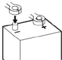
Disconnect Battery
Before you begin, disconnect the battery negative terminal.
natural_image
Simple line drawing of a mechanical setup with two circular components and directional arrows (no text or symbols)Toll-Free Installation Assistance
If you require assistance, contact Technical Support at 1-800-323-4815 from 8:30 a.m. to 7:00 p.m. EST Monday through Friday and from 9:00 a.m. to 5:00 p.m. EST on Saturday. (U.S.A. and Canada only.)
INSTALLATION INSTRUCTIONS
This unit is designed for installation in cars, trucks and vans with an existing radio opening. In many cases, a special installation kit will be required to mount the radio to the dashboard. These kits are available at electronics supply stores and car stereo specialty shops. Always check the kit application before purchasing to make sure the kit works with your vehicle.
Pre-installation
1. Disconnect Battery
Before you begin, always disconnect the battery negative terminal.
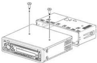
2. Remove Transport Screws
natural_image
Line drawing of a device chassis with ports and connectors (no text or symbols)Universal Installation Using Mounting Sleeve
- Remove the detachable front panel, if it is attached to the chassis, by pushing the "Release" button.
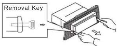
- Slide the mounting sleeve off of the chassis if it has not already been removed. If it is locked into position, use the removal keys (supplied) to disengage it. The removal keys are depicted on page 5.
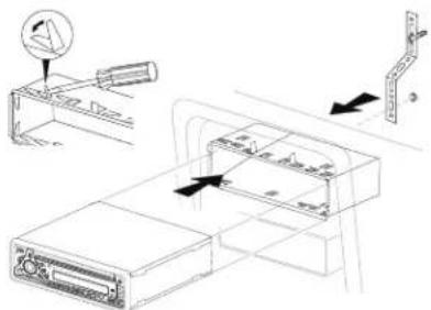
- Check the dashboard opening size by sliding the mounting sleeve into it. If the opening is not large enough, carefully cut or file as necessary until the sleeve easily slides into the opening. Do not force the sleeve into the opening or cause it to bend or bow. Check that there will be sufficient space behind the dashboard for the radio chassis.
- Locate the series of bend tabs along the top, bottom and sides of the mounting sleeve. With the sleeve fully inserted into the dashboard opening, bend as many of the tabs outward as necessary to firmly secure the sleeve to the dashboard.
- Place the radio in front of the dashboard opening so the wiring can be brought through the mounting sleeve.
- Follow the wiring diagram carefully and make certain all connections are secure and insulated with crimp connectors or electrical tape to ensure proper operation.
- After completing the wiring connections, attach the front panel and turn the unit on to confirm operation (vehicle ignition switch must be on). If the unit does not operate, recheck all wiring until the problem is corrected. Once proper operation is achieved, turn the ignition switch off and proceed with final mounting of the chassis.
-
Carefully slide the radio into the mounting sleeve, making sure it is right-side-up, until it is fully seated and the spring clips lock it into place.
-
Attach one end of the perforated support strap (supplied) to the screw stud on the rear of the chassis using the hex nut provided. Fasten the other end of the perforated strap to a secure part of the dashboard, either above or below the radio, using the screw and hex nut provided. Bend the strap, as necessary, to position it. CAUTION: The rear of the radio must be supported with the strap to prevent damage to the dashboard from the weight of the radio or improper operation due to vibration.
-
Re-attach the front panel to the chassis and test radio operation by referring to the operating instructions for the unit.
NOTE: For proper operation of the CD player, the chassis must be mounted within 20^ of horizontal. Make sure the unit is mounted within this limitation.
Kit Installation
If your vehicle requires the use of an installation kit to mount this radio, follow the instructions included with the installation kit to attach the radio to the mounting plate supplied with the kit.
-
Wire and test the radio as outlined in the Universal Installation instructions.
-
Install the radio/mounting plate assembly to the sub-dashboard according to the instructions in the installation kit.
- Attach the support strap to the radio and dashboard as described in the Universal Installation instructions.
- Replace the dashboard trim panel.
ISO Installation
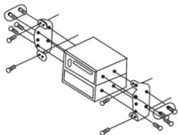
This unit has threaded holes in the chassis side panels which may be used with the original factory mounting brackets of some vehicles to mount the radio to the dashboard. Please consult with your local car stereo shop for assistance on this type of installation.
- Remove the existing factory radio from the dashboard or center console mounting. Save all hardware and brackets as they will be used to mount the new radio.
- Carefully unsnap the plastic frame from the front of the new radio chassis. Remove and discard the frame.
- Remove the factory mounting brackets and hardware from the existing radio and attach them to the new radio. Do not exceed M5 x 9 MM maximum screw size.
Longer screws may damage components inside the chassis.
natural_image
Technical line drawing of a mechanical assembly with no visible text or symbols- Wire the new radio to the vehicle as outlined in the Universal Installation instructions.
- Mount the new radio assembly to the dashboard or center console using the reverse procedure of step 1.
Reconnect Battery
When wiring is complete, reconnect the battery negative terminal.
Remove Radio
To remove the radio after installation, remove the trim ring by lifting in the center and pulling it off from either side. Insert the removal keys straight back until they lock, and then pull the radio out. If removal keys are inserted at an angle, they will not lock properly to release the unit.
WIRING
- Power Antenna (dark blue wire) - Connect to power antenna or amplifier. If not used, tape bare end of wire.
- Accessory/Ignition (red wire) - Connect to existing radio wire or radio fuse.
- Ground (black wire) - Connect to ground terminal or clean, unpainted part of chassis.
- Memory/Battery (yellow wire) - Connect to battery or 12 volt power source that is always live. The radio will not work if this wire is not connected.
- Antenna Connector - Connect the antenna plug from the existing antenna cable (some vehicles require an adaptor).
- Outputs to Amplifier (gray RCA cables) - Connect line out for optional external amplifiers. The red connector is for the right and the white connector is for the left.
- Left Front Speaker
- Right Front Speaker
- Left Rear Speaker
- Right Rear Speaker
Fuses
When replacing a fuse, make sure the new fuse is the correct type and amperage. Using an incorrect fuse could damage the radio. The CD1211 uses one 15 amp fuse located below the wiring connector (15 amp fast blow ATO).
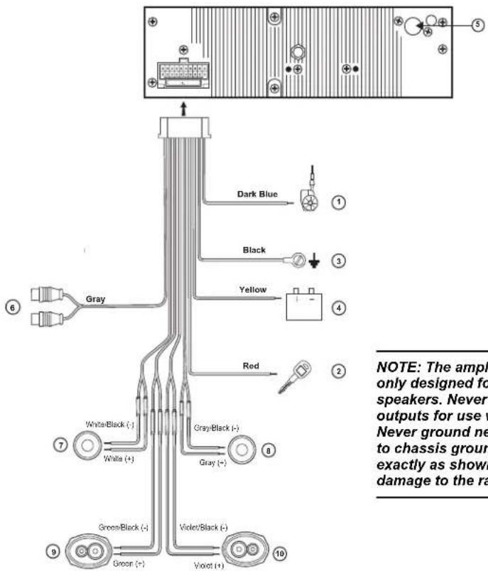
NOTE: The amplifiers in this radio are only designed for use with four speakers. Never combine (bridge) outputs for use with two speakers. Never ground negative speaker leads to chassis ground. Failure to wire exactly as shown may cause electrical damage to the radio.
OPERATING INSTRUCTIONS
Power
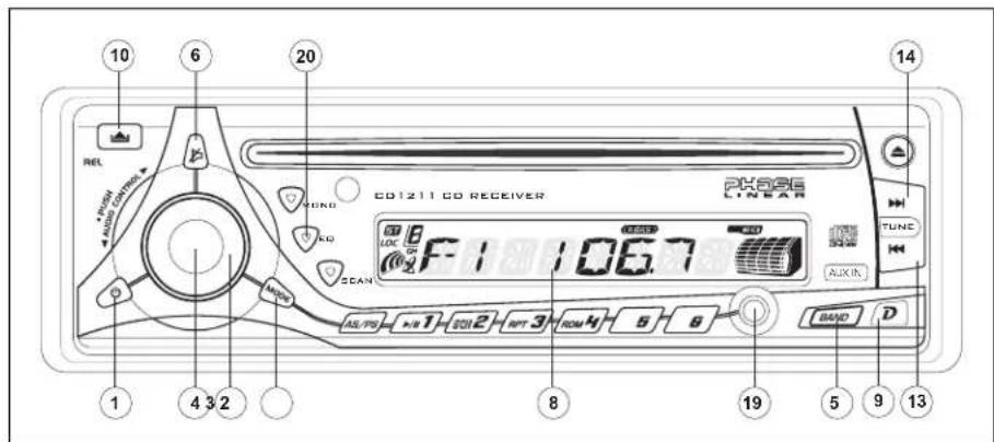
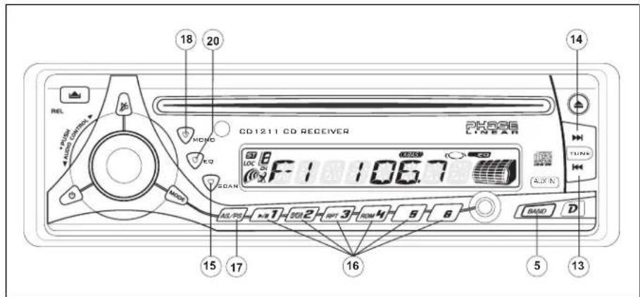
Press the power button (1) or any other button on the face of the receiver to turn the unit on when the ignition switch is on. Press the power button again to turn the receiver off. If the radio was left on when the ignition was last turned off, the receiver will turn on automatically when the ignition switch is again turned on. If the receiver was off when the ignition was last turned off, the receiver must be turned on manually when restarting the vehicle.
Mode
Press MODE (2) to select a different mode of operation as indicated on the display panel. Available modes include Tuner, CD, and Auxiliary Input. During CD player operation, pressing MODE will change to the tuner mode without ejecting the disc. To access the Auxiliary Input mode, press the MODE button until "AUX" is indicated in the display.
Volume
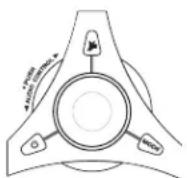
To increase the volume, turn the AUDIO CONTROL (3) clockwise. To decrease the volume, rotate the AUDIO CONTROL counter clockwise. When volume is adjusted, the volume level is shown on the display panel as a number ranging from "00" (lowest) to "100" (highest).
Select
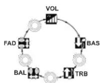
Press the AUDIO CONTROL button (4) to step through the menu of audio functions: volume (VOL), bass (BAS), treble (TRB), balance (BAL), fader (FAD), and volume (VOL). When adjusting audio functions, the unit will automatically exit select mode and return to the normal display after five seconds or when another function is activated.
Bass
Press the AUDIO CONTROL button (4) twice until "BAS" appears in the display. Within five seconds, turn the AUDIO CONTROL (3)
clockwise or counter clockwise to adjust the bass from "-10" to "+10". "00" represents a flat response. The bass level is shown on the display for five seconds or until another function is activated.
Treble
Press the AUDIO CONTROL button (4) three times until "TRB" appears in the display. Within five seconds, turn the AUDIO CONTROL (3) clockwise or counter clockwise to adjust Treble from "-10" to "+10". "00" represents a flat response. The treble level is shown on the display for five seconds or until another function is activated.
Balance
Press the AUDIO CONTROL button (4) four times until "BAL" appears in the display. Within five seconds, turn the AUDIO CONTROL (3) clockwise (or counter clockwise) to adjust Balance between the right and left speakers from "BAL 10R" (full right) to "BAL 10L" (full left). "BAL L=R" represents an equal balance level between the right and left speakers. The balance position is shown on the display for five seconds or until another function is activated.
Fader
Press the AUDIO CONTROL (4) five times until "FAD" appears in the display. Within five seconds, turn the AUDIO CONTROL (3) clockwise or counter clockwise to adjust balance between the front and rear speakers from "FAD 10R" (full rear) to "FAD 10F" (full front). "FAD F=R" represents an equal balance level between the front and rear speakers. The fader position is shown on the display for five seconds or until another function is activated.
X-BASS (BAND)
Press and hold the BAND button (5) for two seconds to activate the X-BASS feature. When listening to music at low volume levels, this feature will boost the bass and treble ranges to compensate for the characteristics of human hearing. When activated, "X-BAS" appears on the display. Press BAND again for two seconds to deactivate this feature.
Audio Mute (MUTE)
Press (6) to mute the audio volume. "MUTE" flashes on the display. Restore volume to the previous setting by pressing the mute button again, adjusting the AUDIO CONTROL, or by pressing any other button on the unit.
Beep Tone
The beep tone feature allows the selection of an audible beep tone to be heard each time a button is pressed on the face of the radio. To access the Beep Tone menu, press and hold the AUDIO CONTROL (4). Turn the AUDIO CONTROL to select from the following Beep Tone options:
- BEEP ALL: Beep is heard any time a button is pressed (function activated).
- BEEP 2ND: Beep is heard only when a secondary function is activated (press and hold).
• BEEP OFF: Beep is not heard.
The equalizer function applies preset sound effects to the unit's audio output signal. Press EQ (20) to activate one of the following operating modes: FLAT, CLASSICS, POP M, ROCK M or DSP OFF. When the equalizer function is activated, the most recently selected bass/treble levels are ignored. If the bass and/or treble levels are adjusted while the equalizer function is active, the equalizer function will revert to FLAT. When the equalizer function is not active, the unit will return to the most recently selected bass and treble levels.
Liquid Crystal Display (LCD)
The liquid crystal display (LCD) panel (8) displays the frequency, time and activated functions of the unit, including an audio level indicator, which appears as a bar graph depicting the audio signal. In addition, the display contains a receive signal indicator that depicts the relative strength of the incoming broadcast frequency.
NOTE: After being subjected to cold temperatures, LCD panels may take longer to respond and visibility of the numbers on the LCD may decrease slightly. The LCD display will return to normal when the temperature increases to a normal range.
Display (D)
When the unit is off, the LCD displays the time of day. When the unit is on, the LCD automatically shows the tuner or CD display, depending on which mode of operation is currently activated.
Display Clock
During tuner or CD operation, press D (9) to display the time of day. After five seconds, the display reverts to tuner or CD display.
Set Clock
- To set the clock, turn the radio on in tuner mode (or any other mode).
- Press D. The time appears on the display.
- Press and hold D until the time display begins flashing.
- While the display is flashing, press the Up Tuning button (14) to adjust hours and the "A" (AM) or "P" (PM) indication. Press the Down Tuning button (13) to adjust minutes.
- After five seconds, the time will set and the display will return to tuner or CD display.
Auxiliary Input
Use the Aux In connector (19) to connect a portable media device for playback through the vehicle sound system.
Front Panel Release
The front panel release button (10) releases the mechanism that holds the front panel to the chassis.
Detaching the Front Panel
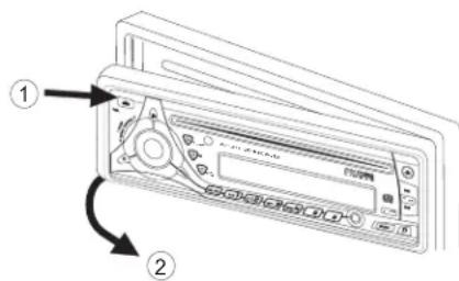
To detach the front panel, first press the front panel release button (10) to release the left side of the panel. Next, grasp the released side and pull it off the chassis. After removing the front panel, store it in the supplied carrying case to protect it from dirt and damage.
REMOVE FRONT PANEL
Re-attaching the Front Panel
To re-attach the front panel, make sure the electrical terminals on the back of the panel are free of dust and dirt, as debris could cause intermittent operation or other malfunctions. Position the right side of the panel in place so
that it is correctly engaged, then lightly press the left side of the panel until the mechanism locks it into place.
Reset Button
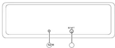
The reset button (11) is located on the front of the chassis and can only be accessed with the front panel removed. The reset circuitry protects the microprocessor circuitry. Since resetting the unit will erase the time and preset memories, it should only be activated upon initial installation after all wiring is complete, or if there is a malfunction of any of the switches on the unit. In these circumstances, pressing the reset button will clear the system and return the unit to normal operation.
Theft Deterrent LED
A light-emitting diode (LED) (12) is located on the chassis behind the front panel and will flash when the panel is removed. The flashing light serves as a visual warning to the would-be thief that the unit has been disabled by removal of the front panel.
TUNER OPERATION
AM/FM Band Selector (BAND)
Press BAND (5) during radio play to switch between three FM bands and one AM band. "F1", "F2", "F3" or "AM" will appear in the display to indicate the band currently selected.
Tuning
Automatic Tuning
Press the Up Tuning (14) button to tune upward in frequency and the Down Tuning (13) button to tune downward in frequency. The unit will automatically stop at the next strong station. If the Local mode is active, the radio will seek the next strong local station when either button is pressed.
Manual Tuning
Press the Up Tuning (14) or Down Tuning (13) button for more than two seconds to select manual tuning mode. "MANUAL" will appear in the display. Press the Up or Down Tuning buttons to move radio frequency up or down two digits at a time. Press and hold the Up or Down Tuning buttons to quickly advance to a certain frequency. Release when the desired frequency is reached. If tuning is not adjusted within five seconds of entering manual tuning mode, the radio will revert to automatic tuning and "AUTO" will appear in the display.
Scan Tuning (SCAN)
Press SCAN (15) to scan upwards through all the strong channels in the current band. The unit will pause and play each station for five seconds, and the station frequency will flash in the display during this time. Press SCAN again to stop scanning and listen to the current station.
NOTE: The Scan function does not work correctly in "MANUAL" mode.
Preset Stations
Up to six stations on each band can be stored as presets and can then be instantly recalled by pressing the associated preset button on the front panel (16) or remote control. To store a station, turn the radio on and select the desired band and station. Press and hold the desired preset button (numbered one through six on the face of the radio or remote control) for more than two seconds. When stored, the preset number will appear in the display. The station is now stored and can be recalled at any time by pressing the corresponding preset button.
Repeat for the remaining five presets on the current band and for all presets on the other three bands.
Automatically Store / Preset Scan (AS/PS)
Automatically Store
Select six strong stations and store them in the current band using the Automatic Store feature. To enable this feature, press and hold AS/PS (17) for more than two seconds. The radio will automatically scan the band in use and enter strong stations into the preset memory positions for that band. After entering the stations into memory, the unit will automatically stop at each station for five seconds so each can be heard. When using the Automatically Store feature, the new stations replace any stations already stored in preset memory for the selected band.
Preset Scan
Press AS/PS (17) to scan the six preset stations in the AM band or all FM bands. The unit will stop at each station for five seconds before continuing to the next preset station, and the preset number will flash on the display during the preset scan. Press AS/PS again to stop scanning and listen to the current station.
Mono/Stereo Selector (MONO)
Press MONO (18) during FM radio operation to select stereo reception of the broadcast signal. Under normal reception, the unit should be left in the stereo mode as indicated by the "ST" designation and the associated signal strength indicator that appear on the display panel when tuned to an FM stereo signal. If the signal is too noisy for comfortable listening, press MONO to switch to mono reception. The "ST" indication will disappear. Press MONO again to return to stereo mode.
Local / Distance Selector
This feature is used to designate the strength of the signals at which the radio will stop during automatic tuning. Distant, or "Dx" is the default setting, allowing the radio to stop at a broader range of signals. To set the unit to select only strong local stations during automatic tuning, press the LOC button on the remote control. "LOCAL" appears in the display.
CD PLAYER OPERATION
Insert CD
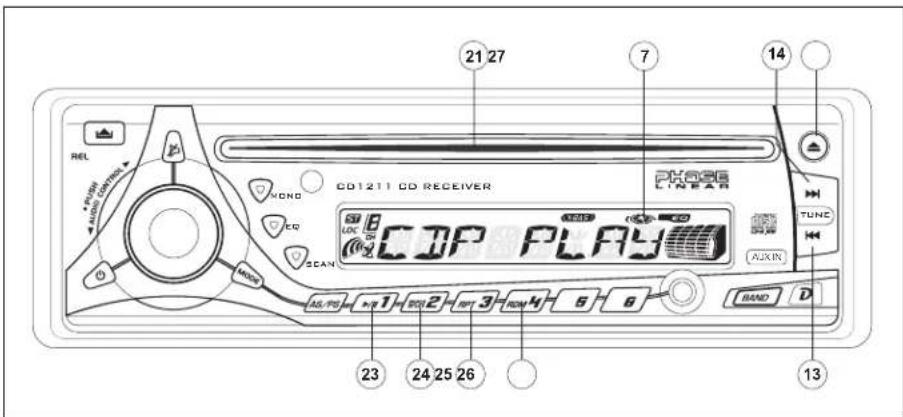
With the label surface facing up, gently insert the disc into the CD slot (21) until the soft-loading mechanism engages and pulls the disc in. Disc play begins, "CDP PLAY" will appear in the display, and the CD icon will become animated. The center of the disc icon (7) illuminates and becomes animated and the track number and elapsed time appear in the display.
NOTE: The unit is designed for play of standard 5" (12 cm.) compact discs only. Do not attempt to use 3" (8 cm.) CD singles in this unit, either with or without an adaptor, as damage to the player and/or the disc may occur. Such damage will not be covered by the warranty on this product.
Track Select
Track select features are used to quickly access the beginning of a particular track when a disc is in play. Press the Up Tuning button (14) to move forward or the Down Tuning button (13) to move backward on the disc to locate the desired track. Track numbers will appear in the display as they are accessed.
Press and hold the Up or Down Tuning buttons to fast forward or fast reverse through a disc.
During either function, the elapsed time will appear on the display. Release the button to resume CD play.
Play/Pause
Press the play/pause button (23) to suspend disc play. "S--PAUSE" will appear in the display, and the center of the disc icon (7) will stop rotating. Press the play/pause button again to resume disc play. The "S--PAUSE" indication will disappear from the display, and play will resume from the pausing point.
Disc Scan (SCN)
During disc play, press SCN (24) to play the first 10 seconds of each track on the disc. "S--SCN" will appear in the display. When the desired track is reached, press SCN again to end the scan function and play the selected track. "S--SCN" will disappear from the display. The scan function will also be canceled when activating the repeat or shuffle functions.
Disc Repeat (RPT)
Press RPT (25) during disc play to continuously repeat the selected track. "S--RPT" will appear in the display. Press RPT again to stop repeating. "S--RPT" will disappear from the display, and regular play will resume. The repeat function will also be canceled when activating the scan or shuffle functions.
Disc Shuffle (RDM)
Press RDM (26) during disc play to play all tracks on a CD in random, shuffled order. "S--SHF" will appear in the display. Press RDM again to stop random play. "S-SHF" will disappear from the display and regular play will resume. The shuffle function will also be canceled when activating the scan or repeat functions.
Disc Eject
Press the eject button (27) to stop CD play and eject the disc. The unit will change to tuner or AUX operation, depending on which mode was in operation prior to disc play. If the disc is not removed from the unit within 15 seconds, the disc will be reloaded to prevent accidental damage. Disc play can be resumed by pressing MODE (2) to choose the CD player function.
CD Player Error Codes
If a problem should develop while operating the CD player, an error code (ER-1, ER-2, etc.) may appear on the display panel. This can indicate a number of problems with the unit, including a mechanical error or an error in the microprocessor control of the player. If an error code should appear, try ejecting and reloading the disc into the player. While the disc is out of the unit, make sure it is clean and undamaged, and then load it correctly. If this does not solve the problem, pressing the reset button (11) may help, but will erase the time and preset memory. If the suggested measures do not solve the problem, contact an approved warranty station near you for further assistance.
REMOTE CONTROL
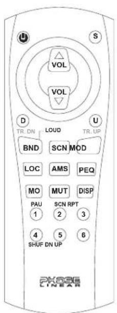
The remote control will allow you to control the basic functions of the CD1211.
The remote control sensor is located on the left side of the front panel to the right of the MONO button (18).
$$ A M S = A S / P S $$
$$ \mathrm{PEQ} = \mathrm{EQ} $$
$$ \mathrm{MOD} = \mathrm{MODE} $$
$$ \mathrm{LOC} = \text { Local / Distant } $$
$$ \mathrm{BND} = \mathrm{BAND} $$
$$ \mathrm{SCN} = \text { Scan }, \mathrm{AM}, \mathrm{FM} $$
$$ \mathrm{MUT} = \text { ↗ } $$
$$ \mathrm{MO} = \mathrm{MONO} $$
$$ D I S P = \text { Clock / Frequency } $$
CARE AND MAINTENANCE
CD Player
The following guidelines will help you extend the life of your CD player:
- When cleaning the vehicle interior, do not get water or cleaning fluids on the unit.
-
The CD player will not operate properly in extreme hot/cold or under damp conditions. In case of such conditions, wait until the vehicle interior reaches a normal temperature or any condensation on the disc player lens has evaporated before using the player.
-
Never insert anything other than round 5" CDs into the player. Attempting to insert CDs of other sizes (even with an adaptor) will cause damage not covered by the warranty.
-
Always remove the CD when the player is not is use.
-
The unit is designed with a vibration dampening CD mechanism to minimize interruption of disc play due to normal vibration in a moving vehicle. However, occasional sound skips may occur when driving on very rough roads. This will not scratch or damage the disc, and normal play will resume when the rough conditions cease.
Compact Discs
CD-R / CD-RW
Depending on media type and method of "recording / burning", some CD-R/RWs may be incompatible with this unit. After "recording / burning" the session must be closed. Please refer to your software's recommended procedures for closing a disc / session. Review your recording software to familiarize yourself with the correct "recording / burning" procedures. We recommend using the latest versions of ROXIO™ or NERO™ burning software.
In addition, this unit will only recognize the CDDA (Compact Disc Digital Audio) format "recorded / burned" onto a CD-R/RW. This unit does not support .MP3, .WMA, .WAV, .OGG or other formats. The CDDA format is the standard format of an "original store bought" CD. When recording / burning a CD-R/RW make sure the CDDA format is selected.
CD Care and Handling
Dirt, dust, scratches and warpage can cause skips in the playback and deterioration of sound quality. Please follow these guidelines to take care of your compact discs.
- Carefully wipe fingerprints, dust and dirt from the disc's playing surface with a soft
cloth. Wipe in a straight motion from the inside to the outside of the disc.
- Never use chemicals such as record sprays or household cleaners to clean CDs, as they can irreparably damage the disc's surface.
- Discs should be kept in their storage cases when not in use.
- Do not expose discs to direct sunlight, high temperatures or high humidity for long periods.
- Do not stick paper, tape or CD labels on disc surfaces, as internal damage may occur.
TROUBLESHOOTING
| Problem Cause Corrective Action | ||
| Does not operate (display does not light) | No power to yellow wire; no power to red wire | Check connection with test light; check vehicle fuse with test light. |
| Inline fuse blown Replace fuse. | ||
| No power to unit Inline fuse blown Check/replace fuse. | ||
| Not all speakers operate | Incorrect splices or connections | Check all splices and connections. |
| Speaker wires shorting to chassis ground or to each other | Check splices; insulate all bare wires. | |
| Blows fuses Power wire shorting to ground Make sure wire is not pinched. | ||
| Speaker wires shorting to ground Make sure wire is not pinched. | ||
| Incorrect fuse or fuse too small Install fuse of correct rating. | ||
| CD skips too much Receiver mount is not solid or backstrap is not secure | Check mounting and backstrap; tighten if needed. | |
SPECIFICATIONS
CEA Power Ratings

Power output: 13 watts RMS X 4 channels into 4-ohms @ ≤ 1% THD+N
Signal to noise ratio: 70dBA below reference. (Reference: 1 watt, 4-ohms)
Frequency response: 20Hz to 20kHz (-3dB), Auxiliary input used as source reference Reference supply voltage: 14.4VDC
CD Player
Signal-to-noise ratio: >90dBA Frequency response: 20Hz-20kHz, -3dB Channel separation: >55dB @ 1kHz D/A converter: 1 Bit/CH
FM Tuner
Tuning range: 87.5MHz-107.9MHz Mono sensitivity: 12dBf 50dB quieting sensitivity (stereo): 16dBf Stereo separation @ 1kHz: >35dB Frequency response: 30Hz-14kHz, ±3dB
AM Tuner
Tuning range: 530kHz-1710kHz Sensitivity @ 20dB signal to noise: 30uV Frequency response: 50Hz-2kHz, -3dB
Auxiliary Input
Input sensitivity: 400mV RMS for 1 watt RMS into 4-ohms Frequency response: 20Hz to 20kHz, -3dB Input impedance: 10 k-ohms
General
Power supply: 11-16 VDC, negative ground
Power Antenna (Blue): 500mAmp Max, current limited protection.
Operating Temp: -10C\~60C
Fuses: 15 amp fast blow ATO
DIN chassis dimensions: 2"H x 7"W x 7"D (51mm x 178mm x 178mm)
Specifications subject to change without notice.
Limited Warranty CD or Multimedia Radios/Headunits
DO NOT RETURN THIS PRODUCT TO THE STORE
Audiovox Electronics Corporation ("the Company") is committed to quality and customer service, and are pleased to offer you this Warranty. Please read it thoroughly and contact the Company at 1-800-323-4815 with any questions.
Who is covered?
The Company extends this warranty to the original retail purchaser of products purchased through an authorized Audiovox retailer in the U.S.A.; Puerto Rico or Canada. This warranty is not transferable or assignable. Proof of purchase is required in the form of an original sales receipt.
What Is covered?
The Company warrants that should this product or any part thereof, under normal use, be proven defective in material or workmanship within 90 days from the date of original purchase, such defect(s) will be repaired or replaced with a new or reconditioned product (at the Company's option) without charge for parts and repair labor.
What is not covered?
This Warranty does not cover the following:
- Damage incurred during shipping or transporting the product to the Company or a service center
- Elimination of car static or motor noise
- Defects in cosmetic, decorative or non-operative structural parts
• Correction of antenna problems
• Costs incurred for installation, removal or reinstallation of the product - Consequential damage to compact discs, USB devices, digital media cards, accessories or vehicle electrical systems
- Damage caused by improper installation, mishandling, misuse, neglect, accident, blown fuse, battery leakage, theft or improper storage
- Products whose factory serial number/bar code label(s) or markings have been removed or defaced
- Damage resulting from moisture, humidity, excessive temperature, extreme environmental conditions or external natural causes
Please review the "Care and Maintenance" section of your Installation and Operation Manual for additional Information regarding the proper use of your product.
Limitations
THE EXTENT OF THE COMPANY'S LIABILITY UNDER THIS WARRANTY IS LIMITED TO THE REPAIR OR REPLACEMENT PROVIDED ABOVE AND, IN NO EVENT, SHALL THE COMPANY'S LIABILITY EXCEED THE PURCHASE PRICE PAID BY PURCHASER FOR THE PRODUCT.
This Warranty is in lieu of all other express warranties or liabilities. ANY IMPLIED WARRANTIES, INCLUDING ANY IMPLIED WARRANTY OF MERCHANTABILITY, SHALL BE LIMITED TO THE DURATION OF THIS WRITTEN WARRANTY. ANY ACTION FOR BREACH OF ANY WARRANTY HEREUNDER INCLUDING ANY IMPLIED WARRANTY OF MERCHANTABILITY MUST BE BROUGHT WITHIN A PERIOD OF 24 MONTHS FROM DATE OF ORIGINAL PURCHASE. IN NO CASE SHALL THE COMPANY BE LIABLE FOR ANY CONSEQUENTIAL OR INCIDENTAL DAMAGES FOR BREACH OF THIS OR ANY OTHER WARRANTY, EXPRESS OR IMPLIED, WHATSOEVER. No person or representative is authorized to assume for the Company any liability other than expressed herein in connection with the sale of this product.
Some states do not allow limitations on how long an implied warranty lasts or the exclusion or limitation of incidental or consequential damage so the above limitations or exclusions may not apply to you. This Warranty gives you specific legal rights and you may also have other rights which vary from state to state.
Obtaining Warranty Service
- To obtain repair or replacement within the terms of this Warranty, call 1-800-323-4815 for the location of a warranty station serving your area.
- You must prepay the initial shipping charges to the Company. The Company will pay the return shipping charges for all warranted products returned to an address within the U.S.A., Puerto Rico or Canada.
- Please package the product securely to avoid shipping damage. We recommend using a carrier that provides tracking service to prevent lost packages. Lost or damaged packages are not covered by this warranty.
- Provide a detailed description of the problem(s) for which you require service.
PHASE LINEAR
Audiovox Electronics Corporation
150 Marcus Boulevard
Hauppauge, NY 11788
1-800-323-4815
www.audiovox.com
©2007 Audiovox
v.083107
- Contents
- Installation Requirements
- Tools and Supplies
- Speaker Requirements
- Disconnect Battery
- Toll-Free Installation Assistance
- INSTALLATION INSTRUCTIONS
- Pre-installation
- Disconnect Battery
- Remove Transport Screws
- Universal Installation Using Mounting Sleeve
- Kit Installation
- ISO Installation
- Reconnect Battery
- Remove Radio
- WIRING
- Fuses
- OPERATING INSTRUCTIONS
- Power
- Mode
- Volume
- Select
- Bass
- Treble
- Balance
- Fader
- X-BASS (BAND)
- Audio Mute (MUTE)
- Beep Tone
- Liquid Crystal Display (LCD)
- Display (D)
- Display Clock
- Set Clock
- Auxiliary Input
- Front Panel Release
- Detaching the Front Panel
- Re-attaching the Front Panel
- Reset Button
- Theft Deterrent LED
- TUNER OPERATION
- AM/FM Band Selector (BAND)
- Tuning
- Automatic Tuning
- Manual Tuning
- Scan Tuning (SCAN)
- Preset Stations
- Automatically Store / Preset Scan (AS/PS)
- Automatically Store
- Preset Scan
- Mono/Stereo Selector (MONO)
- Local / Distance Selector
- CD PLAYER OPERATION
- Insert CD
- Track Select
- Play/Pause
- Disc Scan (SCN)
- Disc Repeat (RPT)
- Disc Shuffle (RDM)
- Disc Eject
- CD Player Error Codes
- REMOTE CONTROL
- CARE AND MAINTENANCE
- CD Player
- Compact Discs
- CD-R / CD-RW
- CD Care and Handling
- SPECIFICATIONS
- FM Tuner
- AM Tuner
- General
- Limited Warranty CD or Multimedia Radios/Headunits
- DO NOT RETURN THIS PRODUCT TO THE STORE
- Who is covered?
- What Is covered?
- What is not covered?
- Limitations
- Obtaining Warranty Service
- PHASE LINEAR
Brand : JENSEN
Model : CD1211
Category : Uncategorized