
DW5066 - Regulator Audac - Free user manual and instructions
Find the device manual for free DW5066 Audac in PDF.


| Product Type | Digital All-In-One Wall Panel (Regulator) |
| Dimensions (W x H x D) | 153 x 94 x 55 mm |
| Built-in Depth | 37 mm |
| Weight | 0.2 kg |
| Power Supply | +24V DC via system PI port (Pin 3 White-Green) |
| Display | 2.5" Graphic Color LCD, 65k colors |
| Line Input (Unbalanced) | Stereo RCA connectors, sensitivity +8dB to -6dB, SNR >95 dB, THD+N <0.02% |
| Microphone Input (Balanced) | XLR connector, sensitivity -14dB to -50dB, SNR >75 dB, THD+N <0.05%, +15V phantom power (software selectable) |
| Control Functions | Volume (0 to -70dB), input source selection, mute, bass and treble adjustment (±9dB each) |
| Number of Controllable Zones | Up to 8 zones |
| Connection Interface | 8-pin Euro Terminal Block, compatible with CAT6 twisted pair cable (max 300m) |
| RS485 Bus Termination | Jumper on rear panel, must be placed when single panel is connected |
| Configurable Addresses | W001 to W008 (set via software) |
| Installation Type | Flush mount with installation box (plastic WB5065/FG or steel WB5065/FS), cutout 135 x 75 mm |
| Operating Environment | Indoor use, wall thickness 7-25 mm (gypsum/wood) or mortar (brick/stone) |
| Maintenance | Clean with dry, soft cloth; do not use liquids or solvents |
| Safety | Installation and modification only by qualified personnel; disconnect power before servicing |
| Spare Parts / Accessories | Installation boxes (WB5065/FG plastic, WB5065/FS steel); no internal spare parts specified |
Frequently Asked Questions - DW5066 Audac
User questions about DW5066 Audac
0 question about this device. Answer the ones you know or ask your own.
Ask a new question about this device
Download the instructions for your Regulator in PDF format for free! Find your manual DW5066 - Audac and take your electronic device back in hand. On this page are published all the documents necessary for the use of your device. DW5066 by Audac.
USER MANUAL DW5066 Audac
Digital All-In-One Wall Panel

www.audac.eu
2 AUDAC
Index
Introduction
Chapter 1: Overview of DW5066
Overview front panel
Front panel description
Overview rear panel
Rear panel description
Chapter 2: Quick start guide
Chapter 3: Installing, Connecting & Configuring 12
Installing 12
Connecting 13
Configuring 16
Chapter 4: Using the DW5066
Chapter 5: Additional information
Technical specifications 24
Using the DW5066 as a local output 25
AUDAC
4 AUDAC
Introduction
Digital All-In-One Wall Panel
The DW5066 is an All-in-one wall panel designed to work in combination with AUDAC digital matrix systems. This wall panel has a graphic display and can control the routing, volume, bass, treble and mute for multiple zones or outputs (up to 8) on one system. Besides those control functions, it also provides the possibility to connect a microphone and a stereo line input source. The DW5066 wall panel should be connected with UTP/FTP Cat6 (or better) cable.
The following functions of multiple zones can be controlled:
– Volume within a range of 0dB to -70dB
– All input sources can be selected
- Mute can be activated
– Bass within a range from -9dB to +9dB
– Treble within a range from -9dB to +9dB
The microphone input on the wall panel is connected with a female XLR connector, while the line inputs are performed using RCA connectors.
Chapter 1
Overview front panel
The front panel of the DW5066 wall panel contains a 2.5" Graphic color LCD display with an unbalanced line input connected by RCA connectors and a balanced microphone input connected by an XLR connector. Each input is accommodated with a push-lock gain control potentiometer and a Clip indicator LED. A big rotatable function selection push dial is provided below the LCD display.
![graph TD A["Unbalanced line input"] --> B["Line IN"] C["Push-lock gain control potentiometer with clipping LED"] --> D["MIC IN"] E["Balanced microphone input"] --> F["Line IN"] G["2.5" Graphic color LCD display"] --> H["Rotatable function selection dial"] I["AUDAC"] --> J["Output"]](/content/2026/05/789592/images/19c1325028bd7e16c9deb101d8e40186c91e8950d07cf14d8db2eef79e1dc52a.jpg)
Front panel description
Unbalanced line input
An unbalanced stereo audio source can be connected to these RCA connectors, creating an additional local input.
Push-Lock gain control potentiometer with clipping LED
The sensitivity for the line and microphone inputs can be adjusted with these potentiometers. Through the push-lock mechanism, they can be opened and hidden again by pressing them. Above every potentiometer is a clipping indicator LED provided which illuminates when clipping of the input signal occurs. When this LED is lit, the signal is distorted and the level should be reduced by turning back the potentiometer. The sensitivity for the line and microphone input can be adjusted between the ranges of 0dB and -∞ dB.
Balanced microphone input
A balanced microphone can be connected to this XLR input connector, which allows message announcements from a remote input. For powering condenser microphones, there's the possibility to provide +15V phantom power to this microphone input. (Software selectable)
2.5" Graphic color LCD display
This graphical color LCD display gives a clear overview of all the functions and settings of the wall panel.
Rotatable function selection dial
The big rotatable dial enables you to control all functions and settings of the wall panel by just three simple actions: Rotate left, Rotate right and Push. Actions such as browsing between the zones, increasing the volume, selection of the audio source, ... can be done by rotating the dial left and right. Actions such as confirming, cancelling, toggling between settings, proceeding and returning to the previous window can be done by pushing the button.
Overview rear panel
The rear panel of the DW5066 contains an 8 pin connector to connect the wall panel to the matrix system and a jumper which is meant to terminate the RS485 databus. A detailed description of how the DW5066 should be connected, can be found in the chapter “Connecting the DW5066”. The jumper to terminate the databus should always be placed when only one wall panel is connected to the databus, and is always provided and placed by delivery.

Chapter 2 Quick start guide
This chapter guides you through the setup process for a basic project where a DW5066 wall panel should be connected to a digital audio matrix. Make sure the digital audio matrix is installed correctly and is powered off when connecting the DW5066 wall panel.
Connect the DW5066 wall panel to the Matrix system with a twisted pair CAT6 cabling with a maximum cable length of 300 meters. Make sure the DW5066 is connected to one of the PI ports on the rear side of the digital audio system (Only PI 1-8 can handle audio inputs).
Go to the setup menu in the web based interface of the digital audio matrix and go to System configuration. Click on DW5066 to create the desired settings for the DW5066 wall panel.
An unique address should be selected for every connected wall panel. The address for a wall panel always starts with the letter "W". When only one wall panel is connected, the most logical way is to start with address "W001", and increase the address number for every additional wall panel. ("W002" for wall panel 2, "W003" for wall panel 3, ...)
After the desired address is selected, click the “Set Address” button. A message will start blinking on all the DW5066 wall panels connected in your system. When the function selection dial on the wall panel is pressed, the selected address will be assigned to the corresponding wall panel.
Now, the outputs which should be controlled by means of the wall panels and the selectable inputs need to be selected. This can be done in the user interface with the two dropdown lists. When the output or input is selected, it automatically appears inside the listbox. To remove a zone or input from the listbox, select the desired zone or input in the listbox, and click the “Remove Zone” or “Remove Input” button.
Next to the listboxes are several selection & checkboxes shown whereby some presets / restrictions can be made to the corresponding wall panel. After the settings are made, click the “Save to Wall panel” button on the bottom of the window, and your changes will be uploaded to the wall panel.
Your wall panel is now ready for operation.
Chapter 3
Installing, Connecting & Configuring
Installing
For installing the DW5066, two different kinds of flush mount installation boxes are available. The plastic installation box (WB5065/FG) is meant to be used for installation into gypsum, wooden or other kinds of plate walls with a thickness between 7 mm and 25 mm. An installation hole with dimensions 135 x 75 mm should be cut wherein the installation box should be placed. When the wall panel is placed into the installation box and the screws are tightened, the wall panel will be secured to the wall. The second type of installation box is a steel version (WB5065/FS) which can be used for mortar in brick or stone walls. Make sure the installation box is installed upright (notice the text and the sticker on the installation box)
Connecting
The DW5066 wall panels should be connected to the PI (Peripheral Interface) ports on the rear side of the system controller with an UTP CAT6 twisted pair cable. 10 PI ports are available (PI1 to PI10) where 8 of them support additional digital audio inputs (PI1 to PI8). So make sure the DW5066 wall panels are connected to PI ports ranging from 1 to 8. The other two PI ports PI9 and PI10 can only be used to connect digital control devices and do not support digital audio transfer.
The maximum cable length between the matrix system and the wall panel may not exceed 300 meters.
System PI Port PINOUT (RS485, Digital Audio, +24V DC):

Pin 1
Pin 2
Pin 3
Pin 4
Pin 5
Pin 6
Pin 7
Pin 8
White-Orange AUDIO TX A
Orange
White-Green
Blue
White-Blue RS485 B
Green
White-Brown AUDIO RX A
Brown
AUDIO
+24V
RS485
GND
AUDIO
AUDAC
ATTENTION
The twisted pair cabling must always be ‘straight’. In case of self made cabling, it must be wired as described in this chapter to make
the system work properly.
The twisted pair cable should be connected to the 8-pin Euro-Terminal block connector on the rear side of the wall panel. The connector starts with Pin1 on the left side to Pin8 on the right side. These Pin's should be connected to the corresponding Pin's of the RJ45 connector.

DW5066 Connector PINOUT
Pin 1 White-Orange AUDIO RX A
Pin 2 Orange AUDIO RX B
Pin 3 White-Green +24V DC
Pin 4 Blue RS485 A
Pin 5 White-Blue RS485 B
Pin 6 Green GND
Pin 7 White-Brown AUDIO TX A
Pin 8 Brown AUDIO TX B
Connection possibilities
A wall panel with additional audio input can be connected to every PI port supporting digital audio transfer (PI1 to PI8). Multiple wall panels can be connected to one PI port, when only one wall panel on every port supports additional audio channels. Up to 8 additional digital audio inputs can be connected to one matrix system.
Connections which WORK
![graph TD A["Central Device"] --> B["Module 1"] A --> C["Module 2"] A --> D["Module 3"] A --> E["Module 4"] A --> F["Module 5"] A --> G["Module 6"] A --> H["Module 7"] A --> I["Module 8"] A --> J["Module 9"] A --> K["Module 10"] A --> L["Module 11"] A --> M["Module 12"] A --> N["Module 13"] A --> O["…](/content/2026/05/789592/images/27fb51ccd8209f609fac436953ec7deca83e366bd98ebbbc19ec514b9b520baf.jpg)
Multiple wall panels (only one with audio input) on one PI port
![graph TD A["Module 1"] --> B["Control Panel"] B --> C["Module 2"] C --> D["Checkmark"] D --> E["Output"] style A fill:#f9f,stroke:#333 style B fill:#ccf,stroke:#333 style C fill:#cfc,stroke:#333 style D fill:#fcc,stroke:#333 style E fill:#ffc,stroke:#333](/content/2026/05/789592/images/4c3b8fdb563ea3b4c36f7d5075d65ae9dee90bf4eba27cfd161c79dbc6d05913.jpg)
Multiple wall panels with audio input on multiple PI ports
Connections which DON'T WORK
![graph TD A["Control Unit"] --> B["Module 1"] A --> C["Module 2"] A --> D["Module 3"] A --> E["Module 4"] A --> F["Module 5"] A --> G["Module 6"] A --> H["Module 7"] A --> I["Module 8"] A --> J["Module 9"] A --> K["Module 10"] A --> L["Module 11"] A --> M["Module 12"] A --> N["Module 13"] A --> O["Mo…](/content/2026/05/789592/images/3f3f96d9f296313581906edcea10773d59e7bb7d22b29bd4d86923d1b0cd092d.jpg)
Multiple wall panels with audio input on one PI port
Configuring
Before the DW5066 can be operational, the configurations should be made. First of all, an address needs to be assigned and the available inputs need to be defined.
Follow these steps to configure:
1) Go to the “Setup” menu and click “System configuration”. Now you have the possibility to choose between “Paging”, “DW5066” and “DW3020/4020”. To configure the settings for the DW5066 wallpanels, click on the corresponding button. Now a window is displayed which provides all the configuration possibilities for the DW5066. On the left side, a dropdown list is displayed whereby the address for the DW5066 can be selected. The address can be selected between “W001” and “W008”. Logically, you start with address “W001” for the first wall panel, and increases for every additional wall panel. After the desired address is selected, click the “Set address” button. After this button is pressed, the DW5066 will start blinking. To confirm the selected address with the wall panel, click the big rotary button on the front of the wall panel. When this button is pressed, the address will be assigned to the selected wall panel.
2) The outputs which you want to control with the selected wall panel can be selected by means of the "Controlled Outputs" dropdown list. When selecting an output in this dropdown list, the output name will appear in the listbox below. The outputs can be removed from this listbox by selecting them, and clicking the "Remove output" button.
3) Selectable inputs for the wall panel can be found in the “Selectable inputs” dropdown list. All inputs that are available on the R2 can be selected in this dropdown list, such as the direct line inputs, the peripheral inputs, the fiber inputs, the priority inputs and the integrated DSP signals. When selecting an input signal in this list, the signal name will appear in listbox below. The input signals can be removed from this listbox by selecting them, and clicking the “Remove Input” button. A maximum of 24 signal inputs can be selected. The inputs which are selected in this listbox, are available for all zones which can be controlled by this DW5066 wall panel. Those inputs are not linked with the quick menu like the inputs on the DW3018/4018 are.
4) Certain actions such as Volume change, Input change, Mute change, Tone control change and settings change can be blocked by checking the checkboxes.
5) The microphone input has the possibility to provide +15V phantom power to power condenser microphones. The pantom power can be switched ON and OFF by clicking the “Enable Mic Phantom” checkbox. This setting can also be changed in the DW5066 settings menu. (If “Block settings menu” is not checked)
6) The Backlight level, screensaver and screensaver delay can be set by means of three dropdown boxes. This setting can also be changed in the DW5066 settings menu. (If “Block settings menu” is not checked)
7) When the settings are made, press the "Save to Wall panel" button and the settings will be sent to the selected DW5066 wall panel.
Previously made settings can be retrieved from the wall panel by clicking the “Load from Wallpanel” button. Hereby, the settings which are stored in the wall panel will be displayed in this window, making it possible to make any changes to the current settings.
Chapter 4 Using the DW5066
When the DW5066 is correctly installed, connected and configured, the wall panel is ready for operation. The standard screen of the DW5066 will give an overview of all outputs which are configured to be controlled by means of the DW5066 wall panel. The output names displayed on this screen correspond with the output settings which are set in the user interface of the matrix.
| Zone 1 |
| Zone 2 |
| Zone 3 |
| Zone 4 |
| Zone 5 |
| Settings |
The main screen provides an overview of the zone names. You can scroll to the desired zone by rotating the selection dial. The zone names will illuminate one by one, when rotating the dial. When the desired zone is selected, you can proceed to the zone settings by pushing the selection dial. The screen has the possibility to display up to five zone names (+ settings) when more than 5 zones are configured, you can scroll further down. The latest option is always the "Settings" button. Click this button when you want to make any changes to the wall panel settings.

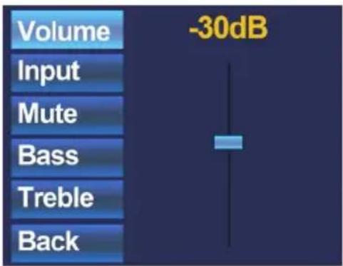
When the desired zone is selected, you will proceed to the settings menu for the corresponding zone. Settings such as Volume control, Input signal selection, Mute and Tone control can be made for the corresponding zone. On the left side of the display all the possible settings are displayed, and scrolling between the settings can be done by rotating the selection dial. The settings will illuminate one by one, when rotating the dial. When the desired setting is selected, you can change it by pushing the dial. For example, when Volume is selected, the attenuation on top of the fader will illuminate and the volume can be changed by rotating the dial. When the volume is set to the desired level, press the dial again to scroll between the settings. You can select the input source by rotating the dial until "Input" illuminates.
| Volume | Off |
| Input | Input 1 |
| Input 2 | |
| Mute | Input 3 |
| Input 4 | |
| Bass | Input 5 |
| Input 6 | |
| Treble | Input 7 |
| Back |
When "Input" is lit, you can push this button and you will be redirected to the input selection window. This window shows all (configured) input channels which can be selected. The displayed input names correspond with the input names which are configured in the matrix settings. You can scroll through the inputs by rotating the selection dial, and you can select the desired input by pushing the dial.
| Volume |
| Input |
| Mute |
| Bass |
| Treble |
| Back |
When the input selection is made, you can scroll further through the settings menu and make other changes such as muting, and changing the tone control. When the zone should be muted, just scroll to the "Mute button" and push the selection dial. When the selection dial is pushed, there will be toggled between "Mute" and "Unmute".
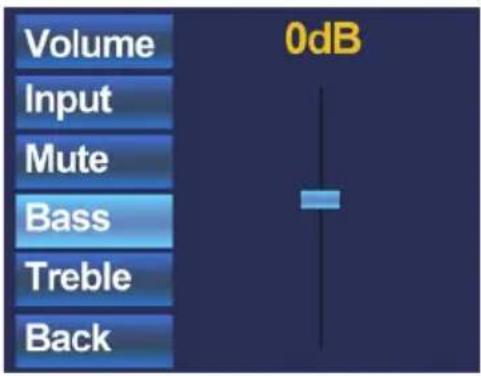
The latest settings which can be changed to the zones are the two band tone control. The tone control can be activated by selecting the "Bass" and "Treble" buttons, and the adjustment of the tone control works with a fader just as the volume control. You can increase and decrease the high and low tones the same way as adjusting the volume, by simply rotating the selection dial. The Bass and Treble both can be adjusted between the ranges of +9dB and -9dB.

The latest selection button is the "Back" button. By clicking this button, you will return to the main screen where zone selection can be made.
| Zone 1 |
| Zone 2 |
| Zone 3 |
| Zone 4 |
| Zone 5 |
| Settings |
When returning back to the main menu, the latest selectable option is "Settings". By selecting this option, changes to the settings of the wall panel can be made. After clicking this button, you will be redirected to the settings menu. The settings menu shows different options like: "Mic Phantom", "Backlight", "Screensaver" and "Info".
| Mic PhantomBacklightScreensaverInfoBack | Phantom:ON |
With the “Mic Phantom” option, the 15V DC phantom power to the microphone input on the wall panel can be enabled and disabled, while the “Backlight” option enables you to adjust the backlight intensity for the LCD display. With the “Screensaver” option, the desired screensaver and the time before the screensaver shows up can be set. Info shows some more information about the wallpanel and the current software version.
Chapter 5
Technical Specifications
Line input Stereo, RCA input
Sensitivity: +8dB / -6dB
Signal / Noise: > 95 dB
THD+N: < 0.02
Microphone input Balanced, XLR input
Sensitivity: -14dB / -50dB
Signal / Noise: > 75 dB
THD+N: < 0.05
Phantom power 15V DC
Display 2.5" LCD, 65k colours
Connector 8-pin Euro Terminal block
Dimensions 153 x 94 x 55 mm
Built-in Depth 37 mm
Weight 0.2 Kg
Installation standard BS4662 - 2 gang
Using the DW5066 as local output
An additional feature of the DW5066 is that it can be used as a local audio output. The signal from a direct output of the system controller can be copied and simultaneously made available on the DW5066. This can be useful for monitoring, recording and some other purposes. One of both audio inputs (RCA or XLR) will be lost in this case
A small modification shall be made on the internal connections of the DW5066.
This action may only be performed by qualified service personnel and make sure the wall panel is disconnected from the system while making this modification!!
A description how this modification shall be made is described below.
1) The back cover of the DW5066 wall panel shall be removed. This can be done by carefully untightening the four screws on the back side of the unit.
2) The internal PCB of the DW5066 will be visible. Each of both connectors (RCA or XLR) will have a wire connected to the PCB Board. Depending of which connector shall be used as audio output, the corresponding wire shall be disconnected. The other connector simply stays connected.

3) After the wire for the corresponding connector has been unplugged, it shall be plugged into the Line Output connector on the left side of the PCB.
4) The connector which is connected to the Line Output connector now will work as a local line audio output.
5) After the modification of the internal connections has been made, combine the back cover again with the front part of the wall panel and tighten the four screws to make it complete again.
6) Connect the wall panel to the system by using twisted pair CAT6 (or better) cable as described before in this instruction manual. The configuration for which signal should be made available on this output shall be configured on the user interface of the system controller.
The pin configuration is as following:
Cinch (RCA):
Tip: Signal
Sleeve: Ground
White: Left
Red: Right
XLR:
Pin 1: Ground
Pin 2: Right
Pin 3: Left
Notes
- 2 AUDAC
- INDEX
- INTRODUCTION
- 4 AUDAC
- DIGITAL ALL-IN-ONE WALL PANEL
- CHAPTER 1
- OVERVIEW FRONT PANEL
- FRONT PANEL DESCRIPTION
- UNBALANCED LINE INPUT
- PUSH-LOCK GAIN CONTROL POTENTIOMETER WITH CLIPPING LED
- BALANCED MICROPHONE INPUT
- 2.5" GRAPHIC COLOR LCD DISPLAY
- ROTATABLE FUNCTION SELECTION DIAL
- OVERVIEW REAR PANEL
- CHAPTER 2 QUICK START GUIDE
- CHAPTER 3
- INSTALLING, CONNECTING & CONFIGURING
- INSTALLING
- CONNECTING
- SYSTEM PI PORT PINOUT (RS485, DIGITAL AUDIO, +24V DC)
- ATTENTION
- DW5066 CONNECTOR PINOUT
- CONNECTION POSSIBILITIES
- CONFIGURING
- FOLLOW THESE STEPS TO CONFIGURE
- CHAPTER 4 USING THE DW5066
- CHAPTER 5
- TECHNICAL SPECIFICATIONS
- USING THE DW5066 AS LOCAL OUTPUT
- CINCH (RCA)
- NOTES
Brand : Audac
Model : DW5066
Category : Regulator