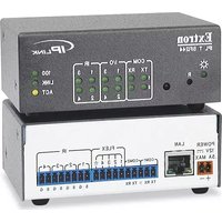
IPL T SFI244 - Network Interface Extron - Free user manual and instructions
Find the device manual for free IPL T SFI244 Extron in PDF.


| Product Type | Ethernet Control Interface |
| Model | IPL T SFI244 |
| Brand | Extron |
| Dimensions (H x W x D) | 1.7" x 4.3" x 3.0" (4.3 cm x 10.9 cm x 7.6 cm) |
| Weight | 0.7 lbs (0.3 kg) |
| Power Supply | External 12 VDC, 1A; Input 100-240 VAC, 50-60 Hz |
| Power Consumption | 12 VDC, 0.5 A |
| Mounting Options | Rack, furniture, or projector mount (optional kits) |
| Ethernet Port | 1 x RJ-45, 10/100Base-T, half/full duplex with autodetect |
| Serial Ports | 2 x RS-232 (captive screw connector), 300-115200 baud |
| IR Ports | 4 x IR output (captive screw connector), 30 kHz to 1 MHz |
| Flex I/O Ports | 4 x analog/digital input/output (captive screw connector) |
| IR Learning | Yes, via front panel IR receiver |
| Web Server | Built-in, up to 200 simultaneous sessions |
| Supported Protocols | ARP, ICMP, IP, TCP, UDP, DHCP, HTTP, SMTP, Telnet |
| Memory | 7.25 MB nonvolatile user memory |
| Firmware Upgrade | Via built-in web server (S19 file) |
| Operating Temperature | +32 to +122°F (0 to +50°C) |
| Storage Temperature | -40 to +158°F (-40 to +70°C) |
| Humidity | 10% to 90% noncondensing |
| Safety Compliance | CE, c-UL, UL; meets UL 2043 (plenum) and UL 60950 |
| EMI Compliance | CE, C-tick, FCC Class A, ICES, VCCI |
| Spare Parts & Repairability | No user-serviceable parts; refer servicing to qualified personnel |
| Warranty | 3 years parts and labor |
Frequently Asked Questions - IPL T SFI244 Extron
User questions about IPL T SFI244 Extron
0 question about this device. Answer the ones you know or ask your own.
Ask a new question about this device
Download the instructions for your Network Interface in PDF format for free! Find your manual IPL T SFI244 - Extron and take your electronic device back in hand. On this page are published all the documents necessary for the use of your device. IPL T SFI244 by Extron.
USER MANUAL IPL T SFI244 Extron
Safety Instructions • English
This symbol is intended to alert the user of important operating and maintenance (servicing) instructions in the literature provided with the equipment.
This symbol is intended to alert the user of the presence of uninsulated dangerous voltage within the product's enclosure that may present a risk of electric shock.
Caution
Read Instructions • Read and understand all safety and operating instructions before using the equipment.
Retain Instructions • The safety instructions should be kept for future reference.
Follow Warnings • Follow all warnings and instructions marked on the equipment or in the user information.
Avoid Attachments • Do not use tools or attachments that are not recommended by the equipment
manufacturer because they may be hazardous.
Power sources • This equipment should be operated only from the power source indicated on the product. This equipment is intended to be used with a main power system with a grounded (neutral) conductor. The third (grounding) pin is a safety feature, do not attempt to bypass or disable it.
Power disconnection • To remove power from the equipment safely, remove all power cords from the rear of the equipment, or the desktop power module (if detachable), or from the power source receptacle (wall plug).
Power cord protection • Power cords should be routed so that they are not likely to be stepped on or pinched by items placed upon or against them.
Servicing • Refer all servicing to qualified service personnel. There are no user-serviceable parts inside. To prevent the risk of shock, do not attempt to service this equipment yourself because opening or removing covers may expose you to dangerous voltage or other hazards.
Slots and openings • If the equipment has slots or holes in the enclosure, these are provided to prevent overheating of sensitive components inside. These openings must never be blocked by other objects.
Lithium battery • There is a danger of explosion if battery is incorrectly replaced. Replace it only with the same or equivalent type recommended by the manufacturer. Dispose of used batteries according to the manufacturer's instructions.
This equipment has been tested and found to comply with the limits for a Class A digital device, pursuant to part 15 of the FCC Rules. Operation is subject to the following two conditions:
- This device may not cause harmful interference.
- This device must accept any interference received, including interference that may cause undesired operation.
The Class A limits are designed to provide reasonable protection against harmful interference when the equipment is operated in a commercial environment. This equipment generates, uses, and can radiate radio frequency energy and, if not installed and used in accordance with the instruction manual, may cause harmful interference to radio communications. Operation of this equipment in a residential area is likely to cause harmful interference, in which case the user will be required to correct the interference at his own expense.
Copyright
© 2010 Extron Electronics. All rights reserved.
Trademarks
All trademarks mentioned in this manual are the properties of their respective owners.
Contents
Introduction ...... 1
About this Manual 1
About the IPL T SFI244 Interface 1
Features 1
Installation and Operation .... 3
Installation Overview 3
Mounting the IPL T SFI244 Interface 3
UL Guidelines for Rack Mounting 3
Rack Mounting 4
Furniture or Projector Mounting 5
Rear Panel Features and Cabling 6
Power 6
Ethernet/LAN 7
Serial Communication 7
Identification 8
Operation 8
Front Panel Indicators 8
Resetting the Unit 9
Connection and Configuration .....11
Connecting the Hardware 11
Ethernet Connection 11
Serial Connection 12
IR Connection 13
Flex I/O Connection 14
Configuring the Hardware 14
PC Configuration 14
IPL T SFI244 Interface Configuration 15
Communication and Control ....18
Ports Overview 18
Flex I/O Ports 18
Bidirectional Serial Control Interface Ports 21
Communication with the Interface 22
Web Server 22
IR Learning 30
Programmer's Guide for the Telnet and Web
Browser 32
Using the Command/Response Table 32
Customization 42
Server Side Includes 42
Query String 43
Code Examples 45
URL Encoding 51
A/V Device Control 52
Custom Web Pages 52
Telnet (Port 23) 53
Direct Port Access (Ports 2001
Through 2002) 54
Troubleshooting 55
Power connections 55
Data connections 55
Specifications, Part Numbers, and Accessories ....56
Specifications 56
Part Numbers and Accessories 58
Glossary 59
Introduction
This section gives an overview of the manual and describes the Extron IPL T SFI244 and its features. Topics that are covered include:
- About this Manual
- About the IPL T SFI244 Interface
- Features
About this Manual
This manual describes the function, installation, configuration, and operation of the IPL T SFI244 Ethernet control interface.
About the IPL T SFI244 Interface
The IPL T SFI244 interface is an Ethernet-based control interface designed to be used as one of many nodes in a distributed control system environment, or as a stand-alone control interface allowing legacy products to link to today's IP Link®-based networks.
The IPL T SFI244 has one 10-pole, 3.5 millimeter captive-screw connector for the two bidirectional COM ports and the four digital I/O ports. It also has one 8-pole, 3.5 millimeter captive-screw connector for the four IR output ports. The ports are fully software configurable via the 10/100 Ethernet port using a Web-based interface. The IPL T SFI244 only supports the RS-232 protocol (RS-422 and RS-485 protocols are not supported). The IR ports are capable of transmitting both carrier and non-carrier (wired or IR) control data.
The IPL T SFI244 interface can host its own Web pages, stored in flash memory within the devices. It supports Telnet, SMTP (simple mail transfer protocol), ICMP (Internet control message protocol) or ping, and DHCP (dynamic host configuration protocol).
The IPL T SFI244 ships with an external, desktop, 12 VDC, 1A power supply (Extron part #28-071-01), that accepts 100-240 VAC input.
Features
Distributed system architecture — A decentralized architecture ensures fault-tolerance throughout the system and stand-alone reliability.
IR remote control — Infrared remote control allows “learning” of commands to control A/V devices.
Easy component configuration — Using the GlobalViewer ^® software allows point-and-click component configuration and control.
High speed — Provides constant high speed data throughput, with a 6 Mbit/second transfer rate.
User customizable — Tailor the on-board Web pages with advanced programmability, e-mail alerts, and storage to suit your needs and requirements. You can also develop your own Web pages using the GlobalViewer application software.
Direct port access — Use existing software programs to control a device that has no Ethernet support. Any existing Extron product with a serial control port can be interfaced with a LAN.
Built-in multilevel security — User controls access to the devices attached to the interface. Two levels of password protection provide appropriate security.
Easily connected — Serial ports on 3.5 millimeter, captive screw connectors, and RJ-45 male auto-sense 10/100 Mbps Ethernet LAN connection.
I/O ports — Can be used to sense when a switch or relay has been activated (input). Can also be used to activate external relays for power, screens, or projector lift controls (output).
IR ports — Allow control of up to 16 devices, with four IR emitters per port.
Easily configured and controlled —
Using a standard Web browser (such as Microsoft® Internet Explorer®) and Web-based interface.
Using a standard Telnet client application.
Requires no centralized processor to operate within a system.
Choice of mounting options — Can be mounted under a desktop or podium, on a projector mount, or on a rack shelf.
Remote management — Allows you to remotely manage projectors, cameras, video conferencing equipment, switchers, and other A/V equipment.
Multiple protocols supported — Allows use of Telnet, SMTP, ICMP, ARP, and DHCP protocols.
Installation and Operation
This section describes the installation and the operation of the IPL T SFI244. Topics that are covered include:
• Installation Overview
- Mounting the IPL T SFI244 Interface
- Rear Panel Features and Cabling
- Operation
Installation Overview
To install and set up the IPL T SFI244:
- Turn all of the equipment off. Make sure that the video sources (DSS, cable boxes, or other devices), the IPL T SFI244 unit, the output devices (monitors, VCRs, projectors, and so on) and the serial controller are all turned off and disconnected from the power source.
- Mount the IPL T SFI244 (see Mounting the IPL T SFI244 Interface).
- Attach the cables (see Connecting the Hardware).
- Connect power cords and turn on the devices in the following order: output devices (projectors, monitors, speakers), the IPL T SFI244 unit, a serial controller or PC, then all input devices (DSS, cable boxes, and so on).
- Configure the IPL T SFI244 interface through Telnet, then access the IPL T SFI244 using an Internet browser.
Mounting the IPL T SFI244 Interface
UL Guidelines for Rack Mounting
The following Underwriters Laboratories (UL) guidelines pertain to the installation of an IPL T SFI244 unit onto a rack.
-
Elevated operating ambient — If installed in a closed or multi-unit rack assembly, the operating ambient temperature of the rack environment may be greater than room ambient. Therefore, consider installing the equipment in an environment compatible with the maximum ambient temperature specified by the manufacturer [Tma = +32 to +122 ^ (0 to +50 ^)] .
-
Reduced air flow — Installation of the equipment in a rack should be such that the amount of air flow required for safe operation of the equipment is not compromised.
-
Mechanical loading — Mounting of the equipment in the rack should be such that a hazardous condition is not achieved due to uneven mechanical loading.
-
Circuit overloading — Consideration should be given to the connection of the equipment to the supply circuit and the effect that overloading of the circuits might have on overcurrent protection and supply wiring. Appropriate consideration of equipment nameplate ratings should be used when addressing this concern.
-
Reliable earthing (grounding) — Reliable earthing of rack-mounted equipment should be maintained. Particular attention should be given to supply connections other than direct connections to the branch circuit (such as the use of power strips).
Rack Mounting
For optional rack mounting, mount the unit on an RSF 123 1U Rack Shelf (part #60-190-20) (see figure 1) or an RSU 129 standard Universal 1U Rack Shelf (part #60-190-01) (see figure 2). On the standard rack shelf, the unit mounts in one of four locations to the rear of the rack or in one of four locations to the front of the rack.
- If feet were previously installed on the bottom of the IPL T SFI244 unit, remove them.
- Mount the unit on the rack shelf, using two 4-40 x 3/16-inch screws in opposite (diagonal) corners to secure the unit to the shelf.
- Install blank panel(s) or other unit(s) to the rack shelf.
- Insert the shelf into the rack, aligning the holes in the shelf with those in the rack.
- Secure the shelf to the rack using the supplied machine screws. This shelf can be mounted in the front or in the rear of the rack.
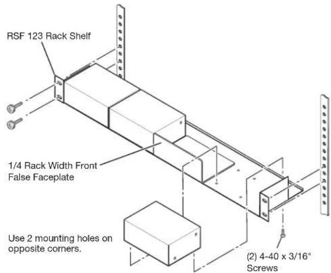
Figure 1. Mounting the Unit on the RSF 123 Rack Shelf
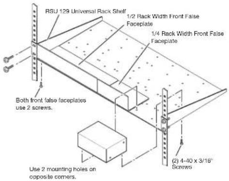
Figure 2. Mounting the Unit on the Standard Shelf
Furniture or Projector Mounting
In addition to using the IPL T SFI244 unit on a rack, it can also be furniture or projector mounted. Furniture mount or projector mount the unit using the optional mounting kit (part #70-212-01, furniture, or part #70-217-01, projector) as follows:
- Attach the mounting brackets to the unit with the machine screws provided (see figure 3).
- If feet were previously installed on the bottom of the unit, remove them.
- For furniture mounting, hold the unit with the attached brackets against the underside of the table or other furniture. Mark the location of the screw holes of the bracket on the mounting surface.
- For furniture mounting, drill 3/32-inch (2 millimeters) diameter pilot holes, 1/4 inches (6.3 millimeters) deep in the mounting surface at the marked screw locations.
- For furniture mounting, insert #8 wood screws into the four pilot holes. Tighten each screw into the mounting surface until just less than 1/4 inches of the screw head protrudes.
- For furniture mounting, align the mounting screws with the slots in the brackets and place the unit against the surface, with the screws through the bracket slots.
- For furniture mounting, slide the unit slightly forward or back, then tighten all four screws to secure it in place.
- For projector mounting, secure the unit to a projector mount or other surface by inserting the mounting bolt through the bracket's slotted hole.
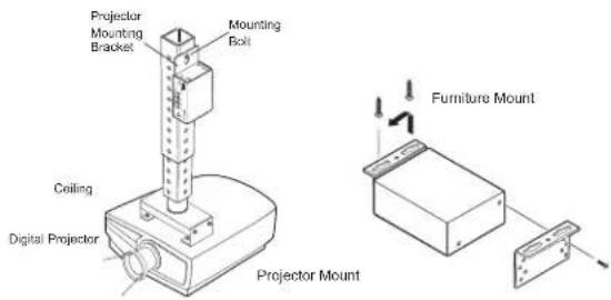
Figure 3. Mounting the IPL T SFI244
Rear Panel Features and Cabling
All connections, including power, input and output, and control, are on the rear panel of the IPL T SFI244 (see figure 4).
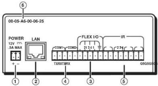
Figure 4. IPL T SFI244 Interface Rear Panel
Power
① Power Connection — Plug the external 12 V power supply into this connector. The power supply is included with the unit.
WARNING: When wiring, The two power cord wires must be kept separate while the power supply is plugged in. Remove power before continuing.
CAUTION: Always use a power supply supplied and or specified by Extron. Use of an unauthorized power supply voids all regulatory compliance certification and may cause damage to the supply and the end product. Unless otherwise stated, the AC/DC adapters are not suitable for use in air handling spaces or in wall cavities. The installation must always be in accordance with the applicable provisions of National Electrical Code ANSI/NFPA 70, article 75 and the Canadian Electrical Code part 1, section 16. The power supply shall not be permanently fixed to building structure or similar structure.
When connecting the power supply, voltage polarity is extremely important. Applying power with incorrect voltage polarity could damage the power supply and the unit. Identify the power cord negative lead by the ridges on the side of the cord.
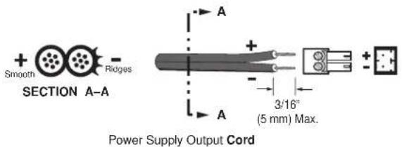
Figure 5. Power Connector Wiring
NOTE: Do not tin the stripped power supply leads before installing the captive screw connector. Tinned wires are not as secure in the captive screw connectors and could pull out.
To verify the polarity before connection, plug in the power supply with no load and check the output with a voltmeter.
Ethernet/LAN
② LAN Activity LED — A blinking yellow LED indicates LAN activity.
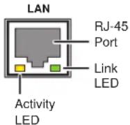
Link LED — The green LED lights to indicate a good LAN connection.
LAN connector — Plug an RJ-45 jack into this socket to connect the unit to a computer network. Use a straight-through cable to connect to a switch, hub, or router, and a crossover cable to connect directly to a PC.
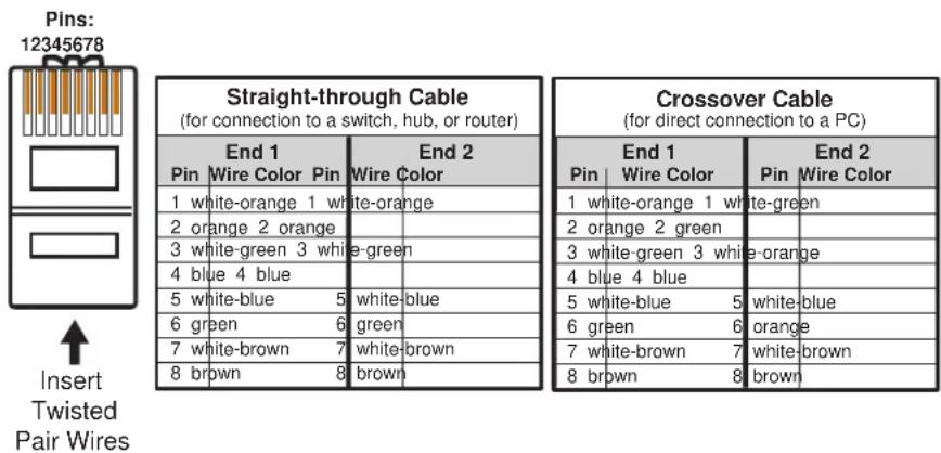
Figure 6. RJ-45 Connector Wiring
Serial Communication
③ Flex I/O ports — Four I/O ports permit connection of switches and sensors to provide input to the system, and contact closure activation of relays for power, screen, or projector lift control (output). Plug a serial cable into this 3.5 millimeter, 5-pole captive screw connector for flexible I/O connection (see Flex I/O Connection).
④ COM ports — Plug a 3.5 millimeter, 5-pole captive screw connector into this socket for serial ports 1 and 2.
Factory default protocol for the control interface is:
RS-232
- 8 data bits
- pacing = 0 milliseconds
• 9600 baud
- 1 stop bit
- handshaking = off
- no parity
⑤ IR ports — Plug an IR cable into this 3.5 millimeter, 8-pole captive screw connector for infrared connections (see IR Connection).
The IPL T SFI244 unit can be used to control display devices, switchers, and other A/V equipment via an RS-232 connection.
Identification
⑥ MAC address — The unique user hardware ID number (MAC address) of the unit (for example, 00-05-A6-00-00-01).
Operation
Connect power cords and turn on the display output devices (projectors, monitors, VCRs), control devices (switchers, scalers, network equipment).
Check indicator LEDs on the PC or laptop, on the unit and on the network hub or router, and so on, to ensure that all devices are plugged in and communicating. The IPL T SFI244 is now ready to be configured (see Connection and Configuration).
If connection or communication problems occur, see Troubleshooting. If the troubleshooting tips do not help, check with your local network administrator, or call the Extron S ^3 Sales & Technical Support Hotline.
Front Panel Indicators
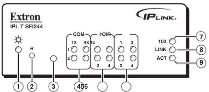
The front panel of the IPL T SFI244 has several indicator LEDs that show the current status of communications to and from the unit. A Reset button (②) is also available from the front panel, in a small recess next to the Power LED.
flowchart
graph TD
    A["Extron IPL T SFI244"] --> B["1"]
    A --> C["2"]
    A --> D["3"]
    A --> E["456"]
    A --> F["R"]
    G["IPLINKx"] --> H["COM TX RX 13 1 3"]
    G --> I["I/OIR 2 4 1 3"]
    G --> J["100 LINK ACT 7 8 9"]
Figure 7. IPL T SFI244 Front Panel
① Power LED — A green LED lights to indicate that the unit is receiving power.
② Reset button (recessed) — See Resetting the unit for details on this multi-function Reset button.
③ IR learning receiver — This smaller infrared receiver “learns” commands from other devices’ IR remote controls. Refer to the IR Learner Software help file for IR Learning procedures.
④ COM ports — A green LED indicates that data is being transmitted or received (TX or RX).
⑤ I/O ports — A green LED indicates that the corresponding I/O port (1-4) is active.
⑥ IR ports — A green LED lights to indicate that the corresponding IR port (1-4) is transmitting data.
⑦ 100 LED — A green LED lights to indicate that the connection speed is 100 Mbps. If
the LED is not lit, the connection speed is 10 Mbps.
⑧ Link LED — A green LED indicates that the unit is connected to an active network.
⑨ Act (Activity) LED — A yellow LED lights to indicate that data is being sent or received.
Resetting the Unit
There are five reset modes available by using the Reset button (②) on the front panel. The Reset button is recessed, so use of a pointed stylus, ballpoint pen, or Extron Tweeker is suggested.
CAUTION: Review the reset modes carefully. Use of the wrong reset mode may result in unintended loss of flash memory programming, the reassignment of ports, or a unit reboot.
| IPL T SFI244 Reset Mode Summary | |||
| Mode Activation Result Purpose/Notes | |||
| Use Factory Firmware | 1 Hold down the recessed Reset button while applying power to the IPL T SFI244.NOTE After a mode 1 reset is performed, update the unit's firmware to the latest version.Do not operate the IPL T SFI244 firmware version that results from the mode 1 reset. This mode temporarily resets the unit to factory default until power is recycled. If you want to use the factory default firmware, you must upload that version again. | The IPL T SFI244 reverts to the factory default firmware. Event scripting does not start if the unit is powered on in this mode. All user files and settings (drivers, adjustments, IP settings, etc.) are maintained.NOTE If you do not want to update firmware, or you performed a mode 1 reset by mistake, cycle power to the unit to return to the firmware version that was running prior to the mode 1 reset. Use the 0Q SIS command to confirm that the factory default firmware is no longer running (look for asterisks following the version number.) | Use mode 1 to revert to the factory default firmware version if incompatibility issues arise with user-loaded firmware.NOTE User-defined Web pages may not work correctly if using an earlier firmware version. |
| Enable Serial Console | 2 Press and release the Reset button. Within 2 seconds, type +++ on the keyboard.NOTE If the three “+’s” (+++) are not entered in the 2-second time frame, the COM port becomes a control port only. | The connected COM port becomes a console port to send SIS commands. Scripting remains on. | Mode 2 enables the SIS console port. |
| Run/Stop Events | 3 Hold down the Reset button for about 3 sec. until the Power LED blinks once, then release and press Reset momentarily (<1 sec.) within 1 second.NOTE Nothing happens if the momentary press does not occur within 1 second. | Mode 3 turns events on or off. | Mode 3 is useful for troubleshooting. |
| Reset all IP Settings | 4 Hold down the Reset button for about 6 sec. until the Power LED blinks twice (once at 3 sec., again at 6 sec.). Then release and press Reset momentarily (for <1 sec.) within 1 second.NOTE Nothing happens if the momentary press does not occur within 1 second. | Mode 4Enables ARP capability.Sets the IP address back to factory default (192.168.254.254).Sets the subnet back to factory default.Sets the default gateway address to the factory default.Sets port mapping back to factory default.Turns DHCP off.Turns events off. | Mode 4 enables you to set IP address information using ARP and the MAC address. |
| Reset to Factory Defaults | 5 Hold down the Reset button for about 9 sec. until the Power LED blinks three times (once at 3 sec., again at 6 sec., again at 9 sec.). Then release and press Reset momentarily (for <1 sec.) within 1 second.NOTE Nothing happens if the momentary press does not occur within 1 second. | Mode 5 performs a complete reset to factory defaults (except the firmware).Does everything mode 4 does.Clears driver-port associations and port configurations (IR/RS-232).Removes button/touchpanel configurations.Resets all IP options.Removes scheduling settings.Removes/clears all files from the IPL T SFI244. | Mode 5 is useful if you want to start over with configuration and uploading, and also to replace events. |
Connection and Configuration
This section discusses how to connect and configure the IPL T SFI244. Topics that are covered, include:
- Connecting the Hardware
- Configuring the Hardware
Connecting the Hardware
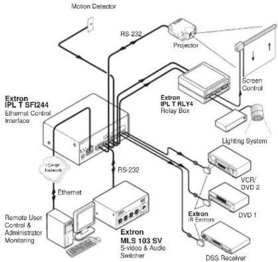
To connect the IPL T SFI244 interface, connect the input and output devices to the unit using figure 8 as a guide. Before connecting the IPL T SFI244 to a local area network (LAN) you must initially connect a PC directly to the IPL T SFI244 and change the default IP address to an address specified by your network administrator (for a LAN connection).
flowchart
graph TD
    A["Extron IPL T SFI244"] --> B["Extron IPL T RLY4 Relay Box"]
    B --> C["Extron IPL T RLY4 Relay Box"]
    C --> D["Extron IPL T RLY4 Relay Box"]
    D --> E["Extron IPL T RLY4 Relay Box"]
    E --> F["Extron IPL T RLY4 Relay Box"]
    F --> G["Extron IPL T RLY4 Relay Box"]
    G --> H["Extron IPL T RLY4 Relay Box"]
    H --> I["Extron IPL T RLY4 Relay Box"]
    I --> J["Extron IPL T RLY4 Relay Box"]
    J --> K["Extron IPL T RLY4 Relay Box"]
    K --> L["Extron IPL T RLY4 Relay Box"]
    L --> M["Extron IPL T RLY4 Relay Box"]
    M --> N["Extron IPL T RLY4 Relay Box"]
    N --> O["Extron IPL T RLY4 Relay Box"]
    O --> P["Extron IPL T RLY4 Relay Box"]
    P --> Q["Extron IPL T RLY4 Relay Box"]
    Q --> R["Extron IPL T RLY4 Relay Box"]
    R --> S["Extron IPL T RLY4 Relay Box"]
    S --> T["Extron IPL T RLY4 Relay Box"]
    T --> U["Extron IPL T RLY4 Relay Box"]
    U --> V["Extron IPL T RLY4 Relay Box"]
    V --> W["Extron IPL T RLY4 Relay Box"]
    W --> X["Extron IPL T RLY4 Relay Box"]
    X --> Y["Extron IPL T RLY4 Relay Box"]
    Y --> Z["Extron IPL T RLY4 Relay Box"]
    Z --> AA["Extron IPL T RLY4 Relay Box"]
    AA --> AB["Extron IPL T RLY4 Relay Box"]
    AB --> AC["Extron IPL T RLY4 Relay Box"]
    AC --> AD["Extron IPL T RLY4 Relay Box"]
    AD --> AE["Extron IPL T RLY4 Relay Box"]
    AE --> AF["Extron IPL T RLY4 Relay Box"]
    AF --> AG["Extron IPL T RLY4 Relay Box"]
    AG --> AH["Extron IPL T RLY4 Relay Box"]
    AH --> AI["Extron IPL T RLY4 Relay Box"]
    AI --> AJ["Extron IPL T RLY4 Relay Box"]
    AJ --> AK["Extron IPL T RLY4 Relay Box"]
    AK --> AL["Extron IPL T RLY4 Relay Box"]
    AL --> AM["Extron IPL T RLY4 Relay Box"]
    AM --> AN["Extron IPL T RLY4 Relay Box"]
    AN --> AO["Extron IPL T RLY4 Relay Box"]
    AO --> AP["Extron IPL T RLY4 Relay Box"]
    AP --> AQ["Extron IPL T RLY4 Relay Box"]
    AQ --> AR["Extron IPL T RLY4 Relay Box"]
    AR --> AS["Extron IPL T RLY4 Relay Box"]
    AS --> AT["Extron IPL T RLY4 Relay Box"]
    AT --> AU["Extron IPL T RLY4 Relay Box"]
    AU --> AV["Extron IPL T RLY4 Relay Box"]
    AV --> AW["Extron IPL T RLY4 Relay Box"]
    AW --> AX["Extron IPL T RLY4 Relay Box"]
    AX --> AY["Extron IPL T RLY4 Relay Box"]
    AY --> AZ["Extron IPL T RLY4 Relay Box"]
    AZ --> BA["Extron IPL T RLY4 Relay Box"]
    BA --> BB["Extron IPL T RLY4 Relay Box"]
    BB --> BC["Extron IPL T RLY4 Relay Box"]
    BC --> BD["Extron IPL T RLY4 Relay Box"]
    BD --> BE["Extron IPL T RLY4 Relay Box"]
    BE --> BF["DSS Receiver"]
    BF --> BG["DVD 1"]
    BG --> BH["VCR/DVD 2"]
    BH --> BI["Lighting System"]
Figure 8. Example Application
Ethernet Connection
This type of connection is used on an ongoing basis to connect the IPL T SFI244 unit and to control switching and display devices through the unit.
- Plug one end of a CAT 5, straight-through Ethernet cable into the rear panel Ethernet connector on the IPL T SFI244. See figure 6 for RJ-45 connector wiring.
- Plug the other end of the Ethernet cable into a network switch, hub, or router connected to an Ethernet LAN or to the Internet.
- Launch your Web browser on your PC and type the Web address that you set up on the IPL T SFI244 (see IPLT T SFI244 Interface Configuration) in the browser's Address field. The initial IPL T SFI244 default Web page is displayed.
Serial Connection
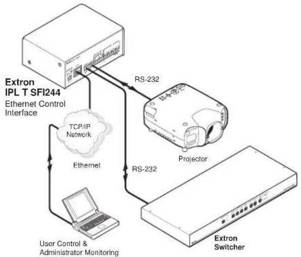
The IPL T SFI244 can be connected to any existing A/V product that has a serial control port.
flowchart
graph TD
    A["Extron IPL T SFI244"] --> B["Ethernet Control Interface"]
    B --> C["TCP/IP Network"]
    B --> D["Ethernet"]
    D --> E["User Control & Administrator Monitoring"]
    B --> F["RS-232"]
    F --> G["Projector"]
    G --> H["Extron Switcher"]
Figure 9. Typical IPL T SFI244 Serial Connection
- Connect one end of a serial cable wired appropriately with a 3.5 millimeter, 5-pole captive screw connector to the rear panel COM port connector of the unit.
| 9-Pin D Connector | Captive Screw Connector | ||||
| Pin | Function | RS-232 | Pin | Function | RS-232 |
| 2 | Receive Data/Receive Data - | RX | 1 | Transmit Data/Transmit Data - | TX |
| 3 | Transmit Data/Transmit Data - | TX | 2 | Receive Data/Receive Data - | RX |
| 5 | Signal Ground | GND | 3 | Signal Ground | GND |
| 4 | Transmit Data/Transmit Data - | TX | |||
| 5 | Receive Data/Receive Data - | RX | |||
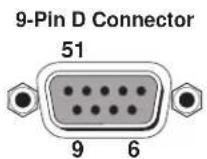
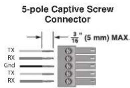
Figure 10. Connector Pinouts
- Connect the other end of the serial cable to the display or switching device to be controlled through the unit.
IR Connection
Wiring for the IR emitter is provided by the IR ports. The IPL T SFI244 provides enough current to power up to four IR emitters with a 100-foot run each, or at least one at up to 4,000 feet. IR control can be applied to devices such as VCRs, audio tape players, or DVD players.
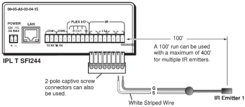
Figure 11. IR connection with 8-pole Captive Screw and IR Emitter
- Connect one end of an IR emitter cable to the rear panel IR port connector of the unit. See figure 11 for connection options.
- Place the head of each IR emitter over or directly adjacent to the controlled device's IR receiver.
IR learning frequencies are 30 kHz to 1 Mhz. See IR Learning for more information on IR learning.
Flex I/O Connection
The IPL T SFI244 provides flexible I/O ports that can be configured to three different operational modes: digital input, digital output and analog input. These ports can interface with devices such as relays, LEDs, and switches, and can also be configured to receive analog voltages for use with photo sensors and level feedback.
- Connect one end of a control cable to the rear panel flex I/O port connectors of the unit.
- Connect the other end of the control cable to the devices that are to be controlled through the unit.
See Establishing or changing system or port settings for more information on configuring the flex I/O ports.
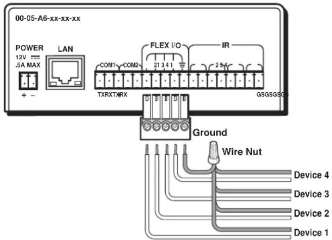
Figure 12. Flex I/O Connection with 5-pole Captive Screw on an IPL T SFI244
Configuring the Hardware
To function together properly, both the controlling PC and the IPL T SFI244 must be configured correctly. The PC must be network-capable, with the proper protocols installed and the hardware configured correctly. The unit must be set to recognize and accept commands, as well as pass them through to the switcher, projector, or other controlled device.
PC Configuration
This manual assumes that you have a Windows ^® PC equipped with an operating network adapter. To allow your PC to work with Extron Ethernet-controlled products, the TCP/IP protocol must be installed and properly configured.
For use on an existing Ethernet LAN intranet, your network administrator can provide you with a unique IP address or confirm whether you need to set up the IPL T SFI244 for DHCP (Dynamic Host Configuration Protocol) to have an address assigned automatically when you sign on.
Initial start up
When you power on the IPL T SFI244 for the first time, there are two ways to set up the IP address.
- Use the ARP (Adress Resolution Protocol) command method.
- Use the direct PC method.
The default Web pages that are pre-loaded on the IPL T SFI244 interface provide a way to reconfigure the IPL T SFI244 once it has an active network connection with IP access. These Web pages are compatible with Internet Explorer ^® (version 5.5 or higher). See Communication with the Interface for information on accessing and configuring the interface.
Once the unit has been reconfigured, an Ethernet (intranet or Internet) connection can subsequently be used to contact or control it. See Ethernet Connection for additional information.
IPL T SFI244 Interface Configuration
Configuring the IPL T SFI244 using the ARP command
You can make use of the ARP command to set up an IP address for your IPL T SFI244. The ARP command tells your computer to associate the IPL T SFI244 unit's MAC address with the assigned IP address. You must then use the ping command to access the IPL T SFI244 unit, at which point the device server's IP address will be reconfigured.
NOTE: To use this setup method, both your computer and IPL T SFI244 interface must be connected to the same LAN. Or, you can use a crossover Ethernet cable to connect the device server directly to your computer's Ethernet card.
Use ARP to configure the IP address as follows:
- Obtain a valid IP address for your IPL T SFI244 from your network administrator.
- Obtain the IPL T SFI244 unit's MAC address from the label on its rear panel.
- If the unit has never been configured and is still set for factory defaults, go to step 4. If not, perform a Mode 4 system reset. See Resetting the Unit for detailed information on reset modes.
CAUTION: The IPL T SFI244 unit must be configured with the factory default IP address — 192.168.254.254 — before executing the ARP command, as described in the following steps.
- Access the command prompt, then execute the arp -s command.
Enter the desired new IP address and the MAC address (the MAC address is located on the rear panel's upper right corner) for the IPL T SFI244 unit. For example:
arp -s 10.13.170.15 00-05-A6-00-0A-90
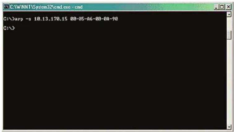
Figure 13. Executing the ARP Command
- Execute a ping command by typing your new IP address in the command prompt. For example:
ping 10.13.170.15
After issuing this command, the unit changes to the new address and starts responding to the ping requests, as shown below. The IPL T SFI244 unit's IP address should now be updated to the new address, and then you can reconnect using either Telnet or the Web to verify that the update was successful.
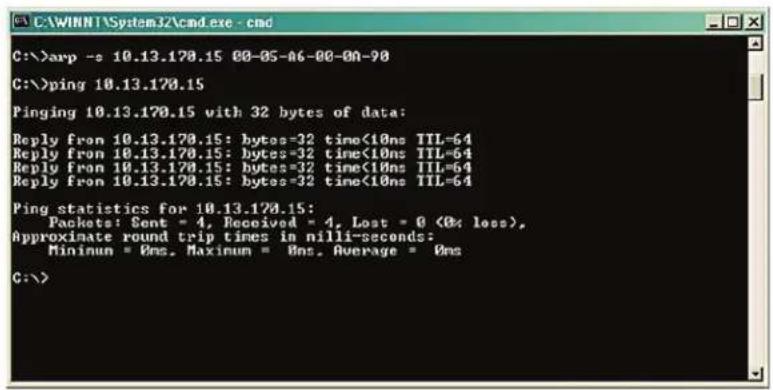
Figure 14. Unit Response to a Ping Request
- After verifying that the change was successful, issue the arp -d command in the command prompt. For example:
arp -d 10.13.170.15 removes 10.13.170.15 from the arp table
or
arp -d* removes all static IP addresses from the arp table.
Configuring the IPL T SFI244 using direct PC connection
This type of connection is used initially to connect to and configure the IPL T SFI244. The unit's default settings (IP address, subnet mask, and [optional] administrator name and password) must be changed in order to use the unit on an intranet (LAN) or on the Internet (WAN).
- Plug one end of a CAT 5, crossover Ethernet cable into the rear panel Ethernet connector on the IPL T SFI244. See figure 6 for RJ-45 connector wiring.
- Plug the other end of the Ethernet cable into the Ethernet port on your PC.
- Right-click on the Network Neighborhood or My Network Places icon on your Windows (98, 2000, NT, ME, XP) desktop and select properties from the menu.
- Select Internet Protocol (TCP/IP) from the list and click on Properties. (If you are using Windows 2000, right-click Local Area Connection and select Properties from the menu, then select Internet Protocol (TCP/IP) from the list and click on Properties again.) If Internet Protocol (TCP/IP) is not on the list, it must be added (installed). Refer to your Windows user manual or the online Help system for information on how to install the TCP/IP protocol.
- Write down your current IP address and subnet mask below. If your PC is set to "Obtain an IP address automatically," make a note of that, instead.
IP Address:
Subnet Mask:

- Click on Specify an IP address or Use the following IP address (depending on your operating system), and leave the default gateway blank. Enter the following values:
IP address: 192.168.254.253
Subnet Mask: 255.255.0.0
- Save the changes and exit the Network setup. Reboot the PC, if required, for the changes to become effective.
- Launch your Web browser (Internet Explorer), and type "http://192.168.254.254/index.html" in the Address field. The IPL T SFI244 default Web page is displayed. See IPL T SFI244 Interface Configuration for more information on configuring your unit.
- After configuring the IPL T SFI244 interface, repeat steps 3 and 4 to change your TCP/IP settings back to their original configuration.
Firmware upgrades
Firmware upgrades become available as improvements are made to the versatility and functionality of the IPL T SFI244. These upgrades are available for download from the Extron Web site. See Upgrading the firmware for more information on upgrading the firmware.
Communication and Control
This section describes communication with the IPL T SFI244 interface as well as A/V device control. Topics that are covered, include:
- Ports Overview
- Communication with the Interface
- Programmer's Guide for the Telnet and Web Browser
- Customization
• A/V Device Control - Troubleshooting
Ports Overview
Flex I/O Ports
Extron flex I/O ports are configurable input or output ports designed to provide connectivity to various devices such as motion detectors, alarms, lights, LEDs, buttons, photo (light) sensors, temperature sensors, or relays. All flex I/O ports are tied to a common ground, but can be individually configured to operate in one of three different modes:
- Digital Input
- Digital Output
- Analog Input
These ports can be configured by using the default Web pages of the IPL T SFI244 Web Server (see figure 15; also see Establishing or changing system or port settings) or by dynamically using the Simple Instruction Set™ commands (see Programmer's Guide for the Telnet and Web Browser) via Telnet, scripts, or Web pages.
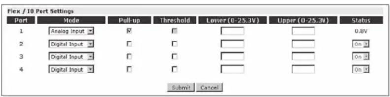
Figure 15. Default Web Page for Flex I/O
Digital input
When a flex I/O port is configured as a digital input, the port measures two states: 1 or 0; On or Off; high or low. A closed circuit = a logic 1 and an open circuit = a logic 0.
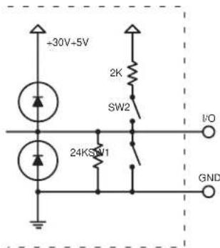
Figure 16. Equivalent Digital Input Circuit
The Digital Input mode has two configurable options:
-
The ability to turn on an internal pull-up resistor to +5 VDC (shown below as SW2)
-
Adjustable detection threshold voltages
The default threshold voltages follow standard TTL logic: a voltage below 0.8 VDC is measured as logic low and a voltage above 2.0 VDC is measured as logic high. Using an adjustable threshold, the integrator can select the proper high and low voltages for the installation.
NOTE: In the figure below, the SW2 switch is turned closed, activating the +5 VDC and 2K pull-up resistor.
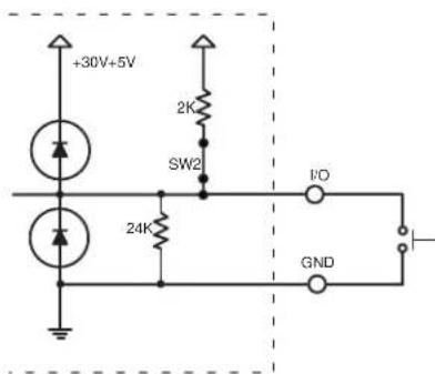
Figure 17. Sample Wiring for a Digital Input Reading an External Pushbutton Switch
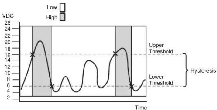
If the integrator selects threshold voltages that are more than 0.1 V apart, a deadband, or hysteresis, will be established.
In the following example, the lower threshold voltage is set at +6 VDC and the upper threshold is set at +16 VDC. The shaded bands show state changes on the logical outputs.
The range between 6-16 VDC is the deadband in which the signal can fluctuate without affecting the input state.
line
| Time | VDC | |------|-----| | 0 | 4 | | 1 | 8 | | 2 | 12 | | 3 | 16 | | 4 | 20 | | 5 | 18 | | 6 | 14 | | 7 | 10 | | 8 | 6 | | 9 | 4 | | 10 | 6 | | 11 | 8 | | 12 | 10 | | 13 | 12 | | 14 | 14 | | 15 | 16 | | 16 | 18 | | 17 | 20 | | 18 | 22 | | 19 | 24 | | 20 | 26 |Figure 18. High and Low Transitions of Adjustable Threshold with Deadband (Hysteresis)
Digital output
When a flex I/O port is configured as a digital output, it offers two output states: "on" and "off". When the port is set to an "on" state, (SW1 is closed), the I/O pin is connected to ground (each I/O port is capable of sinking 250 mA max). When the port is set to the "off" state, (SW1 is open), the output pin is floating.
If the application calls for TTL compatibility, SW2 can be selected to provide a 2K pull-up resistor to +5 VDC.
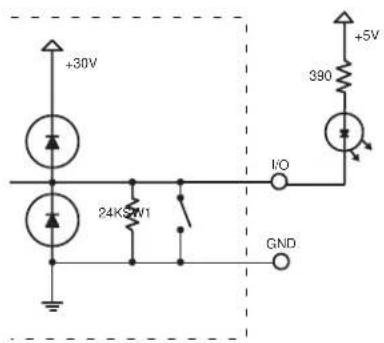
Figure 19. Sample of a Digital Output Port Driving an LED Using an External +5 VDC Source
Analog input
When a flex I/O port is configured as an analog input, the port can measure 0 to 25.3 VDC with 12-bit accuracy. A DC level is indicated by a count from 0-4096 (≈ 6 mv/count).
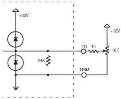
Figure 20. Sample of an Analog Input for a Level Adjustment, Using a 10K Pot
Bidirectional Serial Control Interface Ports
The IP Link ^® family of products has several models that incorporate bidirectional serial control ports. The serial ports allow for control of a wide variety of existing Extron and third-party devices. The most common serial control formats are RS-232, RS-422, and RS-485. With the IPL T SFI244, the captive screw connector is an implementation for the serial control ports.
Captive Screw Connectors — On the IPL T SFI244 unit, all of the serial interface ports are connected on captive screw terminals. When using the ports on the captive screw terminals, only RS-232 control is available, and hardware handshaking is unavailable. Since RS-232 is the most common control interface encountered, this port configuration allows for quick termination.
NOTE: Pacing and handshaking are not supported on captive screw connectors.
All of the bidirectional serial ports are completely software configurable. Baud rates can be set up to 115 Kbs. Using the Simple Instruction Set (SIS) commands found in the Programmer's Guide for the Telnet and Web Browser, these ports can be configured to control most serial devices. Once a port is configured and properly cabled to the controlled device, serial commands can be issued to the port from a Web page, Telnet connection, or by using the advanced scripting capability built into the IP Link product family.
Communication with the Interface
Web Server
The on-board Web server is displayed as a set of default Web pages which can be accessed via a Web browser. These pages are the primary means of communication with, and control through, the IPL T SFI244 interface. Web browsers such as Internet Explorer® (version 5.5 or higher) can be used, but if using Internet Explorer, you must also have Microsoft® Script (version 5.6 or higher).
The PC used to access the Web server must have a connection in common with the IPL T SFI244. In other words, both the unit and the PC should be connected to your local intranet or the Internet.
If you have established passwords for the interface, you will be shown a password window when your browser accesses the IPL T SFI244 (but not when you initially access the Web server, since no passwords have been established). Your level of control over the interface depends on the password you enter in this password screen. If you enter an administrator password, you have control of all matters of configuration. If you enter a user password, you are restricted to control of A/V devices and viewing status.
Accessing and using the Web server
To log on and view system status:
-
Double-click the Web browser icon on your Windows desktop to launch your Web browser.
-
Enter the IP address of the unit (see IPL T SFI244 Interface Configuration) in the Address field at the top of the screen and press the Enter key. The Password window (see figure 21) is displayed if a password has been set (this will not happen the first time you access the interface, as no password is set at the factory).
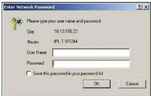
Figure 21. Password Window
The System Status page (see figure 22) is displayed, showing the current IP and port settings of the unit.
![Extron Electronics Status Configuration File Management 800.633.90 Logged on Admin Log Diff Contact Us System Status Below are your Unit's current system settings. To make changes, click on the 'Configuration' tab. System Description Model: IPL T 5F1244 Description: Two BI-Directional Serial Ports [RS232], Four Flex I/O, Four IR Ports Part Number: 60-544-06 Printware: 1.01 Date: 11/04/2003 Time: 5:16 PM IP Settings Unit Name: IPL-T-5F1244-00-07-52 DHCP: Off IP Address: 10.13.174.50 Gateway IP Address: 10.13.0.100 Subnet Mask: 255.255.0.0 MAC Address: 00-05-06-00-07-52](/content/2026/05/789585/images/d501444b1394e8c6cbf5ac69cd336caac57e639bd7d8012b23f26ea00dc200c2.jpg)
Figure 22. System Status Screen
Establishing or changing system or port settings
The System Settings screen is used to initially configure or change configuration of the IPL T SFI244 interface. You may be required to change system settings if your network changes, or if port settings change as you add or change display devices or switchers.
To configure system or port settings:
- Select the Configuration tab. The System Settings screen (see figure 23) is displayed.
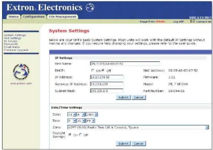
Figure 23. System Settings Screen
- Make changes to the IP settings or date/time settings, as necessary.
-
Click Submit to enter the changes or click Cancel to revert to the previous settings.
-
Click Port Settings on the menu (on the left side of the window) and the Port Settings screen (see figure 24) is displayed.
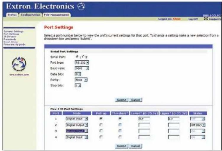
Figure 24. Port Settings Screen
- Select the desired port and make changes to the port settings, as necessary.
- Click Submit to enter the changes or click Cancel to revert to the previous settings.
Controlling IR devices or sending IR commands
In order to send IR commands to IR devices via the default Web pages, do the following:
- Select the File Management tab. The File Management screen (see figure 30) is displayed.
- Upload the IR driver to the box by clicking Browse and locating the appropriate driver. The IR driver file must be named numerically (ranging from 0 to 99).
NOTE: File names must end with an .eir extension (for example, 0.eir or 24.eir).
- Select the Configuration tab.
- Click IR Drivers on the menu (on the left side of the window) and the IR Drivers screen (see figure 25) is displayed. All uploaded IR drivers should be displayed on this page.
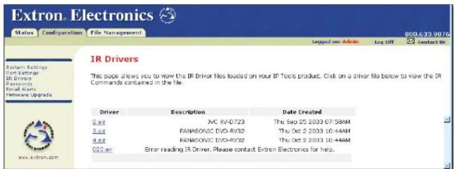
Figure 25. IR Driver Screen
-
Click the IR driver that controls the device. A separate IR interface screen (see figure 26) displays the commands in the driver.
-
Select the port to which the IR command will be sent.
-
Execute the IR command by clicking the command link. The IR LED on the front of the IPL T SFI244 unit blinks a green light verifying that the IR command is being sent.
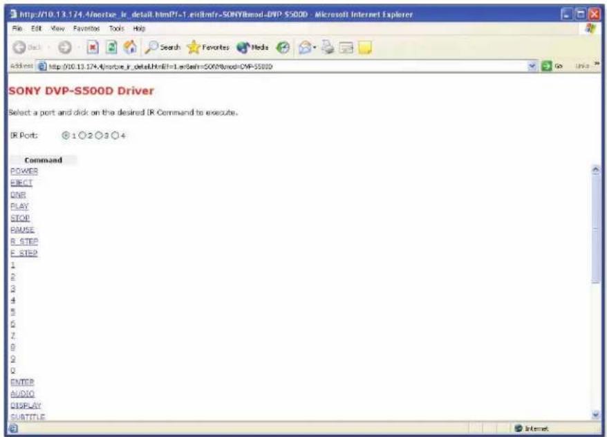
Figure 26. Example of the Default Web Interface of an .EIR File
Setting and changing your passwords
For security reasons you may want to set passwords initially or change passwords either periodically or on a scheduled basis. If passwords have been set, you must log on as an administrator to change the passwords.
To set or change the passwords:
-
Click the Passwords link on the menu (on the left side of the window). The Passwords screen (see figure 27) is displayed.
-
Enter the passwords for the administrator and/or user, then re-enter the same passwords to confirm.
-
Click Submit to enter the changes or click Cancel to revert to previous settings. If the fields are blank, no passwords have been assigned.

Figure 27. Passwords Screen
- Once passwords have been set, you will be required to enter a password (figure 21) whenever you log on to the unit.
NOTE: To clear a password, enter a single space, repeat the entry, and click Submit. If there is no administrator password, your user password will not be saved.
Editing and adding e-mail alerts
If you have created scheduled events or monitoring tasks on the IPL T SFI244, you can write an e-mail alert with a message corresponding to that event or task (for example, a timer notification indicating it's time to replace a projector light bulb). The e-mail alert can notify up to eight recipients at one time.
To edit notification e-mail addresses from the Email Alerts page:
- Click Email Alerts on the menu (on the left side of the window). The Email Alerts screen (see figure 28) is displayed.
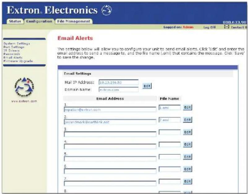
Figure 28. Email Alerts screen
- Click Edit to go into edit mode.
- Add, update, or change the IP address and domain name of your mail server under Email Settings.
- Click Save to keep changes.
- Click the Edit buttons to independently edit each e-mail address and file name.
a. Enter the e-mail address of the alert recipient in one of the numeric mailboxes under Email Address.
b. Enter the name of the file containing the alert message under File Name.
c. Click Save to keep changes to recipient e-mail addresses and file names.
CAUTION: File names must end with an .eml extension.
NOTE: Due to the 7-character limit for full file names, it's advised that you use numeric titles (for example, 1.eml or 24.eml). Numeric titles reduce the characters of the file name and assist in keeping the alert files organized. However, alphabetical titles are permitted.
To finalize your new e-mail alerts within the Web server, do the following:
- Obtain your gateway IP address from your system administrator
- Click System Settings on the menu on the left side of the window.
- Within the System Settings screen (see figure 23), place the gateway IP address into the Gateway IP Address field.
Sending an e-mail alert through Telnet
To complete the process of sending an e-mail alert, you must send it through a Telnet session and receive confirmation. To do so:
- Open a Telnet Session. See Accessing and using Telnet for instructions on how to do this.
- Use the "Send e-mail" SIS command to send the alert to the e-mail address of a numeric mailbox (see figure 28). See Programmer's Guide for the Telnet and Web Browser for specific command code.
For example, the code for sending an alert from the 4th numeric mailbox would be:
Esc 4 SM←
Refer to the GlobalViewer® help file for detailed information on monitoring and scheduling.
Upgrading the firmware
Firmware upgrades become available as improvements are made to the versatility and functionality of the IPL T SFI244 interface. These upgrades are available for download from the Internet.
CAUTION: The firmware file you select to upload must have an .S19 extension. Uploading the incorrect file may cause your unit to stop working.
To upgrade the firmware:
- Click Firmware Upgrade on the menu (on the left side of the window). The Firmware Upgrade screen (figure 29) is displayed.
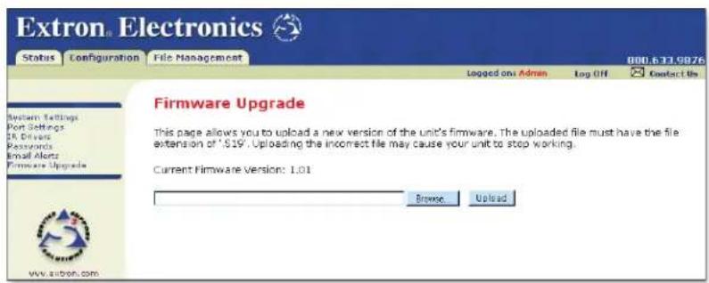
Figure 29. Web Server Firmware Upgrade Screen
- Click Browse to find the most current available version of the firmware.
If you find a later version than the one shown above the box, click Upload to upgrade to the newer version.
CAUTION: If you leave the page before upload is complete, the upload will be cancelled.
Managing files
File Management is a useful tool that allows you to use and upload existing and custom Web pages. Custom pages can be developed using a third-party Web page development program such as FrontPage® or Dreamweaver®. File Management also allows you to remove unnecessary or outdated files when they are no longer needed.
To add or update files:
- Select the File Management tab. The File Management screen (see figure 30) is displayed.
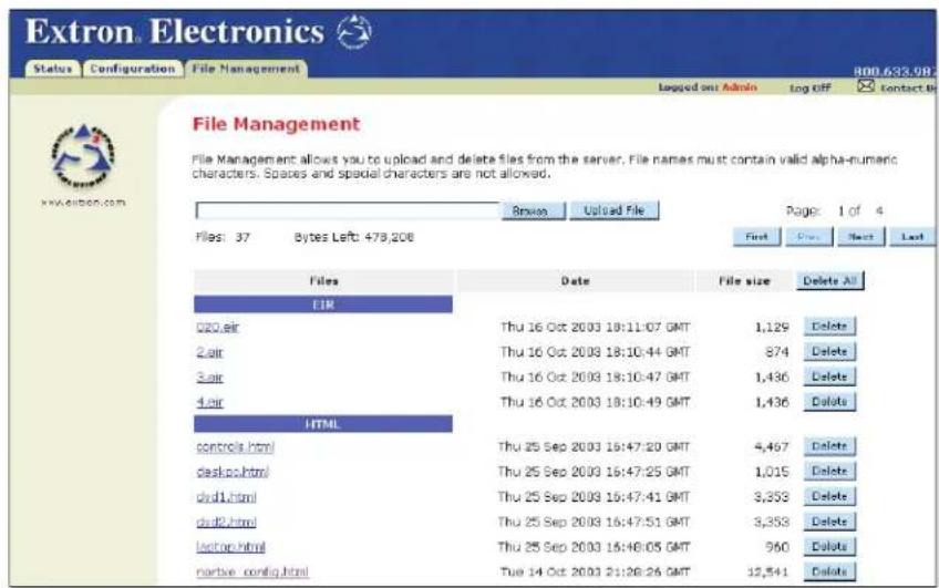
Figure 30. Web Server File Management screen
- Click Browse to locate the file you want to upload.
- Click Upload File to upload the file.
The file is added to the list of files under the Files column. After ten files have been loaded, additional file management pages appear in the page navigation area (on the right side of the screen).
To delete unwanted files:
- Select the File Management tab. The File Management screen (see figure 30) is displayed.
- Find the file you wish to delete under the Files list.
- Click Delete for the file to be deleted. If you wish to delete additional files, wait for the screen to refresh before clicking Delete for the next file.
If you wish to delete all files, click Delete All. The file count will revert to zero and all subsequent pages are deleted.
IR Learning
The IPL T SFI244 IR can "learn" commands from a third-party remote control device in order to control devices such as VCRs, audio tape players, or DVD players. IR learning can be performed in conjunction with GlobalViewer to assist in controlling commonly used functions.
During IR learning, you must hold the device remote between two inches and twelve inches away from the IR pick up device (see figure 31).
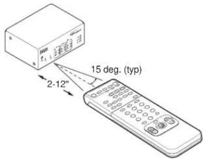
Figure 31. IR remote distance
Creating a driver with the IR Learner software
To use your third-party remote device with the IPL T SFI244, the functions of your third-party driver must be "learned" by the IPL T SFI244. In other words, you must create a driver for your remote control device. You can create a new, custom driver or manipulate an existing driver. Both can be accessed or created through the IR Learner software.
To create a driver for your remote control device:
-
Launch the IR Learner software application. The application window appears; there are no open drivers.
-
Create a new or empty driver by selecting File > New. A driver document is created and its Header tab is selected.
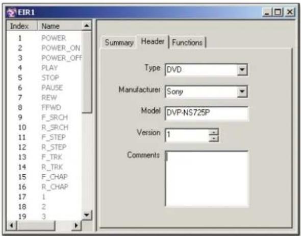
Figure 32. Creating a New Driver
-
Edit the Header fields (see figure 32), the most important of which is Type. The driver is populated with a default set of commands according to the selected device type. A device type of "Other" creates an empty driver with no functions.
-
Add functions by pressing the Add button in the toolbar.
NOTE: User-definable functions can be added to the driver. The names and ordering of user-definable functions can be changed at any time by double-clicking on the function to be renamed. The names and ordering of any default functions cannot be altered.
At this point the driver is populated with unlearned functions.
To learn driver functions:
-
Select those functions that are to be learned (see figure 33). Then, begin a learning session by pressing the Learn toolbar button. A series of messages and windows will guide you through the "learn" process, providing instruction on how to aim the remote, what button to press, and when to release the button.
-
Save the driver by selecting File > Save, or you can add or learn new functions.
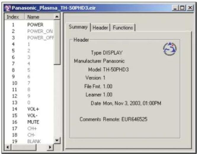
Figure 33. Selecting Driver Functions
See the IR Learner Software help file for more details about IR learning.
Programmer's Guide for the Telnet and Web Browser
Using the Command/Response Table
The following are either Telnet (port 23) or Web browser (port 80) commands. There are some minor differences when implementing these commands via Telnet or via URL encoding using a Web browser. All commands listed below will work using either connection method, but due to some limitations of Web browsers, the encapsulation characters are modified to make sure that the Web browser will properly handle them. All examples in the command/response table show the proper implementation in a Telnet or Web browser session.
NOTE: For Web browsers, all non-alphanumeric characters must be represented as their hex equivalent such as %xx where xx equals the two-character representation of the hex byte that needs to be sent (for example, a comma would be represented as %2C).
Telnet Web Browser
Escape (Hex 1B) W [must not be encoded]
Carriage Return (Hex 0D) Pipe Character ( | ) [must not be encoded]
When using these commands through a Web browser, the URL reference is used below to shorten the examples. This would, in practice, be the full URL of the control interface and Web page reference including all path information (for example, http://192.168.100.10/myform.htm).
To send any of the commands using a Web browser, you need to prefix them with the full URL followed by ?cmd= (see URL Encoding).
NOTE: With Telnet you can use either the "Escape" character or the "W" character, and the carriage return or the pipe character. With the Web browser, you are required to use the "W" character and the pipe character.
In either method {Data} signifies that data will be directed to a specified port and must be encoded if it is non-alphanumeric.
The table on pages 36 through 41 lists the commands that the IPL T SFI244 recognizes as valid, the responses that are returned to the host, a description of each command's function, and the results of executing the command.
NOTE: Upper and lower case text can be used interchangeably except where noted.
Symbol definitions are shown below. An ASCII to HEX conversion table is also provided in figure 34.
![Space → ASCII to Hex Conversion Table Esc 1B CR ØD LF ØA ( 20 ! 21 " 22 # 23 $ 24 % 25 & 26 ' 27 ( 28 ) 29 * 2A + 2B , 2C - 2D . 2E / 2F Ø 30 1 31 2 32 3 33 4 34 5 35 6 36 7 37 8 38 9 39 : 3A ; 3B < 3C = 3D > 3E ? 3F @ 40 A 41 B 42 C 43 D 44 E 45 F 46 G 47 H 48 I 49 J 4A K 4B L 4C M 4D N 4E O 4F P 50 Q 51 R 52 S 53 T 54 U 55 V 56 W 57 X 58 Y 59 Z 5A [ 5B \ 5C ] 5D ^ 5E _ 5F . 60 a 61 b 62 c 63 d 64 e 65 f 66 g 67 h 68 i 69 j 6A k 6B l 6C m 6D n 6E o 6F p 70 q 71 r 72 s 73 t 74 u 75 v 76 w 77 x 78 y 79 z 7A { 7B l 7C } 7D ~ 7E DEL 7F](/content/2026/05/789585/images/20f206a7f3b3af911be7465b4eb863756d890a7158daf84bd21052fc1274f6b4.jpg)
Figure 34. ASCII-to-HEX Conversion Table
Symbol definitions
← = CR/LF (carriage return/line feed)
← = Carriage return (no line feed)
- = Space (hard) character
X1 = Specific port number (01-99) The port number will be represented as two ASCII characters (2 bytes); 00 = All ports
X2 = Command data section
NOTE: For Web encoding only - Data will be directed to specified port and must be encoded (URL encoding) if non-alphanumeric. Since data can include either command terminator, they must be encoded as follows when used within the data section: space (hex: 20) would be encoded as %20 and plus sign (hex: 2B) would be encoded as %2B.
X3 = Greenwich Mean Time (GMT) offset value (-12.0 to +14.0)
X5 = On/off status: 0 = off/disable; 1 = on/enable
X11 = Unit firmware version
X12 = Name is a text string up to 24 characters drawn from the alphabet (A-Z), digits (0-9), minus sign/hyphen (-). No blank or space characters are permitted as part of a name. No distinction is made between upper and lower case. The first character must be an alpha character. The last character must not be a minus sign/hyphen.
X13 = Set local date and time format (MM/DD/YY-HH:MM:SS) for example, 11/18/03-10:54:00 Read local date and time format (day of week, date month year HH:MM:SS) for example, Thu, 18 Nov 2003 18:19:33
X14 = IP address (xxx.xxx.xxx.xxx); leading zeros in each of four fields are optional in setting values, and are suppressed in returned values.
X15 = Mail domain name (for example, extron.com, icia.org)
X17 = Time, in tens of milliseconds, to wait for characters coming into a serial port before terminating (default = 10 = 100 milliseconds, max = 32767)
X18 = Hardware (MAC) address (xx-xx-xx-xx-xx-xx)
X19 = Subnet mask (xxx.xxx.xxx.xxx); leading zeros in each of four fields are optional in setting values, and are suppressed in returned values.
X20 = Time, in tens of milliseconds, to wait between characters coming into a serial port before terminating (default = 2 = 20 milliseconds, max = 32767)
X21 = Parameter to set either Length of message to receive or Delimiter value; # = byte count or single ASCII character decimal
X22 = Verbose/response mode status: 0 = clear, default for Telnet connections; 1 = verbose mode is on; 2 = send tagged responses for queries; 3 = verbose mode is on and tagged responses are sent for queries
NOTE: If tagged responses are enabled, all read commands return the constant string + the data or value, the same as in responses for setting a value. For example, for Esc CN←, the response is lpn• X12 ← rather than just the data (X12 ←).
X23 = Priority status for receive timeout: 0 = priority set to Send Data String command parameters, 1 = priority set to configure received timeout command parameters
X25 = Baud rate: 300, 600, 1200, 1800, 2400, 3600, 4800, 7200, 9600, 14400, 19200, 28800, 38400, 57600, 115200
X26 = Parity: Odd, Even, None, Mark, Space (only first letter is required)
X27 = Data bits: 7, 8
X28 = Stop bits: 1, 2
X29 = Port type: RS-232, RS-422, RS-485 (or 0, 1, or 2, respectively). (X29 = 0 for the SFI244)
[X30] = Flow control: Hardware, Software, None (only first letter is required)
X31 = Data pacing (specified in milliseconds between bytes): 0000-1000 (default = 0 milliseconds)
X33 = Password: maximum length of 12 characters and no special characters.
NOTE: User password cannot be assigned if no administrator password exists, and returns E14. If the administrator password is cleared, then the user password is also removed.
X34 = Daylight saving time: 0 = off/ignore; 1 = on (use in northern hemisphere) (USA); 2 = on (Europe); 3 = on (Brazil)
X35 = Event number: range = 0 - 99 (max.)
X36 = Event buffer: 0 = receive; 1 = user (absolute); 2 = user (relative); 3 = NVRAM
X37 = Event buffer offset: range = 0 - MaxBufferSize
X38 = Event data size: bit; Byte (8-bit); Short (16-bit); Long (32-bit) (only first letter is required)
NOTE: This parameter is case-sensitive.
[X39] = Event data to write.
X40 = I/O mode: 0 = input; 1 = output; 2 = input plus pull-up resistor; 3 = output plus pull-up resistor; 4 = analog in; 5 = analog in w/pull-up; 6 = adjust in (requires X55 & X56 thresholds); 7 = adjust in w/pull-up (requires X55 & X56 thresholds). X55 & X56 thresholds are not required for modes 0-5.
X43 = 0 = off; 1 = on; value = 0-4095, based on 12-bit A to D
X44 = Number of bytes to read
X45 = E-mail recipient number: range = 1 - 64 max
X46 = E-mail recipient address: maximum number of characters for a full e-mail address is 31 characters.
X47 = Name of e-mail file to be sent: the first line of the file is the subject, the rest is the body of the e-mail.
NOTE: E-mail files must have the .eml file extension.
X49 = Default Name: Combination of model name and last 3 pairs of MAC address (for example, IPL-T-SFI244-00-02-3D)
X50 = Redirect: 0 = no redirect; 1-n = redirect serial port from the specified port to allow for a transparent pass-through mode
X52 = Connection's security level: 0 = not logged in; 11 = user; 12 = administrator
X53 = Timeout for data pass-through mode, after which event data can be inserted into the transmit buffer.
X54 = ASCII digit(s) representing numeric value of data element read from event buffer (leading zeros are suppressed)
X55 = Upper transition threshold (0 detection = off) for digital inputs; Lower must be smaller than upper (0-4095 based on 12-bit A to D)
X56 = Lower transition threshold (1 detection = on) for digital inputs; Lower must be smaller than upper (0-4095 based on 12-bit A to D)
NOTE: The default Web pages display X55 and X56 as voltages (100 mV to 24 VDC, upper default = 2 VDC and lower default = 1 VDC). The conversion rate is 162 counts to 1 V.
X57 = IR playback file number (0-99)
X58 = IR function number
X59 = IR playback mode: 0 = play once, 1 = play continuously (send IR command again with mode = 0 to stop mode 1 playback)
X63 = Pulse time in 20 milliseconds per count. If parameter is missing or = 0, pulse length = default (25 counts = 500 milliseconds), max (65536 counts)
X64 = Broadcast repetition rate in seconds (0-256. 0 = disable)
Copyright information
(c) COPYRIGHT 2009, EXTRON ELECTRONICS IPL T SFI244, Vx.xx, 60-544-86 Thurs, 28 Jan 2010 16:29:10
The copyright message is displayed upon connecting to IP Link product via TCP/IP or Telnet. Vx.xx is the firmware version number. The unit's part number, the current date, and time are displayed as well. This is followed by a password prompt.
Password information
The “◀Password:” prompt requires a password (administrator level or user level) followed by a carriage return. The prompt is repeated if the correct password is not entered.
If the correct password is entered, the unit responds with "◀Login Administrator◀" or "◀Login User◀", depending on the password entered. If passwords are the same for both administrator and user, the unit defaults to administrator privileges.
Error responses
When the IPL T SFI244 receives a valid command, it executes the command and sends a response to the host device. If the unit is unable to execute the command because the command contains invalid parameters, it returns an error response to the host.
E10 — Invalid command
E12 — Invalid port number
E13 — Invalid parameter
E14 — Not valid for this configuration
E17 — System timed out
E22 — Busy
E24 — Privilege violation
E25 — Device not present
E26 — Maximum number of connections exceeded
E27 — Invalid event number
E28 — Bad filename/file not found
E31 — Attempt to break port pass-through when not set (A user or software attempted to disable the port redirect feature when it wasn't already set or active.)
References to errors (at command descriptions on the following pages)
^10 = Commands that give E10 (invalid command).
^24 = Commands that give E24 (privilege violation) if not administrator level.
^27 = Commands that may give E27 (invalid event number).
^28 = Commands that may give E28 (file not found).
Command/response table for SIS commands
| Command ASCII (Telnet) URL Encoded (Web) Response | |||
| Bidirectional serial data port | |||
| Send data string | Esc X1 *X17* X20* X21 RS←X2• | WX1 %2A X17%2A X20%2A X21S|X2 | response from command← |
| Configure parameters24 | Esc X1 *X25, X26, X27, X28CP← | WX1 %2A X25%2C X26%2C X27%2C X28CP| | Cpn X1 • Ccp X25, X26, X27, X28← |
| View parameters | Esc X1 CP← | WX1 CP | X25 | , X26, X27, X28← |
| Configure mode24 | Esc X1 *X29CY← | WX1 %2A X29CY| | Cpn X1 • Cty X20← |
| Configure flow control24 | Esc X1 *X30, X31CF← | WX1 %2A X30%2C X31CF| | Cpn X1 • Cfl X30, X31 |
| View flow control | Esc X1 CF← Esc X1 | CF | X30 | , X31← |
| Configure receive timeout24 | Esc X1 *X17* X20* X23CE← | WX1 %2A X17%2A X20%2A X23CE| | Cpn X1 • Cce X17, X20, X23← |
| View receive timeout | Esc X1 CE← | WX1 CE | X17 | , X20, X23← |
| Configure redirect mode24 | Esc X1 *X50* X53CD← | WX1 %2A X50%2A X53CD| | Cpn X1 • Ccd X50, X53← |
| View redirect mode | Esc X1 CD← | WX1 CD | X50 | , X53← |
| Terminate redirect mode24 | Esc X1 *OCD← | WX1 %2A0CD| | Cpn X1 • Ccd0,0 |
| Flex I/O data port | |||
| Set I/O mode (modes 0-5) | X1 *X40| | X1 %2A X40%5B Cpn | X1 • lom X40← |
| Set I/O mode (modes 6-7) | X1 *X40 *X55 *X56[ | X1 %2A X40%2A X55%2A X56%5B Cpn | X1 • lom X40, X55, X56 |
| View I/O mode | X1[ | X1 %5B | X40, X55, X56← |
NOTE:
X1 = Specific port number (01-99)
X2 = Command data section
| X17 = Time to wait for characters coming into serial port before terminating (default = 10 = 100 milliseconds, max = 32767) |
| X20 = Time to wait between characters coming into serial port before terminating (default = 2 = 20 milliseconds, max = 32767) |
| X21 = Parameter to set either Length of message to receive or Delimiter value. |
| X23 = Priority status for receive timeout: 0 = priority set to Send Data String command parameters, 1 = priority set to configure received timeout command parameters |
| X25 = Baud rate: 300, 600, 1200, 1800, 2400, 3600, 4800, 7200, 9600, 14400, 19200, 28800, 38400, 57600, 115200 |
| X26 = Parity: Odd, Even, None, Mark, Space (only first letter is required) |
| X27 = Data bits: 7, 8 |
| X28 = Stop bits: 1, 2 |
| X29 = Port type: RS-232, RS-422, RS-485 (or 0,1, or 2, respectively). (X29 = 0 for the SFI244) |
| X30 = Flow Control: Hardware, Software, None (only first letter is required) |
| X31 = Data pacing: 0000-1000 (default = 0 milliseconds) |
| X40 = I/O mode: 0 = input; 1 = output; 2 = input plus pull-up resistor; 3 = output plus pull-up resistor; 4 = analog in; 5 = analog in w/pull-up; 6 = adjust in (requires X55 & X56 thresholds); 7 = adjust in w/pull-up (requires X55 & X56 thresholds). X55 & X56 thresholds are not required for modes 0-5. |
| X50 = Redirect: 0 = no redirect; 1-n= redirect serial port from the specified port to allow for a transparent pass-through mode |
| X53 = Timeout for data pass-through mode, after which event data can be inserted into the transparent buffer |
| X55 = Upper transition threshold (0 detection = off) for digital inputs |
| X56 = Lower transition threshold (1 detection = on) for digital inputs |
Command/response table for SIS commands (continued)
Command ASCII (Telnet) URL Encoded (Web) Response
| Pulse I/O state ^10 14 | [X1]*3*[X63] | [X1]%2A 3%2A [X63]%5D Cpn | [X1]*Sio [X5]← |
| Toggle I/O state ^10 14 | [X1]*2] | [X1]%2A 2%5D Cpn | [X1]*Sio [X5]← |
| Set I/O state ON | [X1]*1] | [X1]%2A 1%5D Cpn | [X1]*Sio1← |
| Set I/O state OFF | [X1]*0] | [X1]%2A 0%5D Cpn | [X1]*Sio0← |
| View I/O state | [X1] | [X1]%5D | [X43]← |
| IR/serial data port | |||
| Send IR command ^28 | Esc X1 X5[X58, X59]R← | W[X1]%2C [X57]%2C [X58]%2C [X59] | | Irs[X1,X57, X58, X59]← |
| Get IR command info ^28 | Esc X57X58, IR← {description text} | ← | |
| Firmware version/part number/information | |||
| Query firmware version Q Q | [X11]← | ||
| Query verbose version information | 0Q 0Q | sum of responses from 2Q-3Q-4Q← | |
| Query firmware version 1Q 1Q | [X11]← | ||
| Query bootstrap version 2Q 2Q | [X11]← | ||
| Query factory firmware version | 3Q 3Q | [X11 (plus web ver.-desc-UL date/time)]← | |
| Query updated firmware version | 4Q 4Q | [X11 (plus web ver.-desc-UL date/time)]← | |
| NOTE: An asterisk (*) placed after the version number indicates which version is currently running. A question mark (?) indicates that only the factory firmware version is loaded. A caret (^) after the version number indicates the firmware version that should be running, but a Mode 1 reset was executed. The default factory firmware version is loaded. An exclamation point (!) after the version number indicates corrupted firmware.) | |||
| Request part number N N | 60-xxx-yy← | ||
| Request model name 1I | 1I | IPL T SFI244← | |
| Request model description | 2I | 2I | Two Bi-Directional Serial Ports [RS232], Four Flex I/O, Four IR Ports← |
| Request system memory usage | 3I | 3I | # Bytes/Kbytes used out of # Kbytes← |
| Request user memory usage | 4I | 4I | # Bytes/Kbytes used out of # Kbytes← |
NOTE:
x5 = On/off status: 0 = off/disable; 1 = on/enable
x11 = Unit firmware version
x43 = 0 = off; 1 = on; value = 0-4095, based on a 12-bit A to D
x57 = IR playback file number (0-99)
[x58] = IR function number
X69 = IR playback mode: 0 = play once; 1 = play continuously (send IR command again with mode = 0 to stop mode 1 playback) X63 = Pulse time in 20 milliseconds per count
Command/response table for SIS commands (continued)
Command ASCII (Telnet) URL Encoded (Web) Response
| IP setup commands | |||
| Set Unit name21 | Esc X12N← | W|X12|CN| | Ipn•X12← |
| Set Unit name to factory default24 | Esc•CN← | W%20CN| | Ipn•X49← |
| Read Unit name | EscCN← | WCN| | X12← |
| Set time/date24 | Esc X13T← | W|X13|CT| | Ipt•X13← |
| Read time/date | EscCT← | WCT|+ | X13← |
| Set GMT offset24 | Esc X3CZ← | W|X3|CZ|+Ipz | X3← |
| Read GMT offset | Esc CZ← | WCZ| X3← | |
| Set daylight savings time 24 | Esc X34X← | W|X34|CX| | IpxX34← |
| Read daylight savings time | Esc CX← | WCX| X34← | |
| Set DHCP on24 | Esc1DH← | W1DH| | Idh1← |
| Set DHCP off24 | Esc0DH← | W0DH| | Idh0← |
| View DHCP mode | Esc DH← | WDH| X5← | |
| Set IP address24 | Esc X14I← | W|X14|CI| | Ipi•X14← |
| Read IP address | Esc CI← | WCI| X14← | |
| Read hardware address (MAC) | Esc CH← | WCH| X18← | |
| Set subnet mask24 | Esc X19S← | W|X19|CS| | Ips•X19← |
| Read subnet mask | Esc CS← | WCS| X19← | |
| Set gateway IP address24 | Esc X14G← | W|X14|CG| | Ipg•X14← |
| Read gateway IP address | Esc CG← | WCG| X14← | |
| Set administrator password24 | Esc X33A← | W|X33|CA| | Ipa•X33← |
| Clear administrator password24 | Esc•CA← | W%20CA| | Ipa← |
| Read administrator password24 | Esc CA← | WCA| X33← | |
| Set user password24 | Esc X33U← | W|X33|CU| | Ipu•X33← |
| Clear user password24 | Esc•CU← | W%20CU| | Ipu← |
| Read user password24 | Esc CU← | WCU| X33← | |
| Set verbose mode24 | Esc X22V← | W|X22|CV| | VrbX22← |
NOTE: X3 = Greenwich Mean Time (GMT) offset value (12.0 to 14.0) X5 = On/off status: 0 = off/disable; 1 = on/enable
X12 = Name is a text string up to 24 characters drawn from the alphabet, digits, minus sign/hyphen. No blank or space characters are permitted. X13 = Set local date and time format (MM/DD/YY-HH:MM:SS); Read local date and time format (day of week, date month year HH:MM:SS)
X14 = IP address X18 = Hardware (MAC) address X19 = Subnet mask
X22 = Verbose/response mode status: 0 = clear, default for Telnet connections; 1 = verbose mode is on; 2 = send tagged responses for queries; 3 = verbose mode is on and tagged responses are sent for queries X33 = Password: maximum length of 12 characters and no special characters
X34 = Daylight savings time: 0 = off/ignore; 1 = on (use in northern hemisphere) (USA); 2 = on (Europe); 3 = on (Brazil) X49 = Default Name: combination of model name and last 3 pairs of MAC address
Command/response table for SIS commands (continued)
| Command ASCII (Telnet) URL Encoded (Web) Response | |||
| Read verbose mode | Esc CV← | WCV | X22← | |
| Read connection's security level | Esc CK← | WCK | X52← | |
| Configure broadcast mode | Esc X64B← | WX64EB | | BmdX64← |
| View broadcast mode | Esc EB← | WEB | X64← | |
| Get connection count | Esc CC← | WCC | | Number of Connections← |
| File commands | |||
| Get listing | Esc DF← | WDF | | |
| Telnet text responses: Web responses: | |||
| filename x•date/time•length← | var file - new Array(): | ||
| filename x•date/time•length← | file [1] = 'filename1, date1, filesize1'; | ||
| filename x•date/time•length← | file [2] = 'filename2, data2, filesize2'; | ||
| ... ... | file [n] = 'filename n, date n, | ||
| space_remaining•bytes left←← | filesize n'; | ||
| file [n+1] = 'space remaining, bytes left' | |||
| Stream files via Telnet or RS-232 | |||
| Load file to user flash memory ^24 28 | Esc +UF, filesize, filename← {raw unprocessed data from the file up to filesize} Upl | ← | |
| Retrieve file from user flash memory28 | Esc filename SF← | 1B filename 53 46 0D | {4 bytes of filesize, and then raw data from the file} |
| Stream files via port 80 | |||
| Load file to user flash memory Use a POST on port 80, followed by the delimited data to be written to the flash file memory | |||
| Retrieve file from user flash memory | Send a page GET on port 80 followed by WSF | | {The response is raw data from the file} | |
| Example: | http://192.168.254.254/mypage.html?cmd=WSF | | {data from the file mypage.html} | |
| Re-map port designations | |||
| Set Telnet port map24 | Esc port#MT← | Wport#MT | | Pmtport#← |
| Reset Telnet port map24 | Esc 23MT← | W23MT | | Pmt00023← |
| Disable Telnet port map24 | Esc 0MT← | W0MT | | Pmt00000← |
NOTE: X22 = Verbose/response mode status: 0 = clear, default for Telnet connections; 1 = verbose mode is on; 2 = send tagged responses for queries;
3 = verbose mode is on and tagged responses are sent for queries
52 = Connection's security level: 0 = not logged in; 11 = user; 12 = administrator
[X64] = Broadcast repetition rate in seconds (0-256, 0 = disable)
Command/response table for SIS commands (continued)
| Command ASCII (Telnet) URL Encoded (Web) Response | |||
| Read Telnet port map24 | Esc MT← | WMT | | port#← |
| Set Web port map20 | Esc port#MH← | Wport#MH | | Pmhport#← |
| Reset Web port map21 | Esc 80MH← | W80MH | | Pmh00080← |
| Disable Web port map24 | Esc 0MH← | W0MH | | Pmh00000← |
| Read Web port map24 | Esc MH← | WMH | | port#← |
| Set Direct Access port map24 | Esc port#MD← | Wport#MD | | Pmdport#← |
| Reset Direct Access port map24 | Esc 2001MD← | W2001MD | | Pmd02001← |
| Disable Direct Access port map24 | Esc 0MD← | W0MD | | Pmd00000← |
| Read Direct Access port map24 | Esc MD← | WMD | | port#← |
| Web browser specific | |||
| Read response from last URL command | Esc UB← | WUB | | Response from command← |
| Configure e-mail events24 | Esc X45X46,X47CR← | WX45 %2C X46%2C X47R | | IprX45,X46,X47← |
| Read e-mail events | Esc X45 R← | WX45 CR | X46 | ,X47← |
| Send e-mail (event)24 | Esc X45 M← | WX45 SM | | Em|X45← |
| Set mail server IP, domain name24 | Esc X14X15CM← | WX14 %2C X15CM | | Ipm|X14,X15← |
| Read mail server IP, domain name | Esc CM← WCM | X14 | ,X15← | |
| Event control | |||
| Read event buffer memory27 | Esc X35X36,X37,X38 E← | WX35 %2C X36%2C X37%2C X38 E | X54← | |
| Write event memory24 27 | Esc X35X36,X37,X39,X38 E← | WX35 %2C X36%2C X37%2C X39%2C X38 E | | Evt|X35,X36,X37,X39← |
NOTE: X14 = IP address
X15 = Mail domain name
x35 = Event number: range = 0-99 (max)
X36 = Event buffer; 0 = receive; 1 = user (absolute); 2 = user (relative); 3 = NVRAM
X37 = Event buffer offset: range = 0-MaxBufferSize
X38 = Event data size: bit; Byte (8-bit); Short (16-bit); Long (32-bit) (only first letter is required)
x39 = Event data to write
X45 = E-mail recipient number: range = 1-64 max
X46 = E-mail recipient address: max number of characters for full e-mail address is 31 characters
x47 = Name of e-mail file to be sent
X54 = ASCII digit(s) representing numeric value of data element read from event buffer
Command/response table for SIS commands (continued)
| Command ASCII (Telnet) URL Encoded (Web) Response | |||
| Read string from event memory27 | Esc X35X36 X37 X44 FE← | W X35 %2C X36%2C X37%2C X44 FE| | string← |
| Write string to event memory24 27 | Esc string* X35 X36 X37 FE← | Wstring%2A X35%2C X36%2C X37E| | Evt X35 X36 X37 string← |
| Start events24 27 | Esc 1AE← | W1AE| | Ego← |
| Stop events24 27 | Esc 0AE← | W0AE| | Est← |
| Read number of events running | Esc AE← WAE | | | Enm#####← |
| Reset (zap)/erase commands | |||
| Erase user-supplied Web page and files24 28 | Esc filenameEF← | WfilenameEF| | Del•filename← |
| Erase flash memory24 | Esc ZFFF← | WZFFF| | Zpf← |
| Reset all device settings to factory26 | Esc ZXXX← WZXXX | | | Zpx← |
| Absolute system reset24 | Esc ZQQQ← | WZQQQ| | Zpq← |
| NOTE: Reset all settings/memories. The ZQQQ command resets everything (all settings, adjustments, the IP address, and subnet mask) to the factory default values. Files in flash memory are also erased by this command. The firmware version does not change. The IP address is reset to 192.168.254.254, the subnet mask is reset to 255.255.0.0. | |||
NOTE:
X35 = Event number: range = 0-99 (max)
X36 = Event buffer: 0 = receive; 1 = user (absolute); 2 = user (relative); 3 = NVRAM
x37 = Event buffer offset: range = 0-MaxBufferSize
X44 = Number of bytes to read
Customization
You can use various methods to make the IPL T SFI244 interface perform customized functions or to alter the unit's embedded Web pages. Server Side Includes (SSIs) make it possible to send commands to the IPL T SFI244 itself, or to devices connected to its control ports. Customization is also possible by writing query strings and inserting them into Web pages stored on the IPL T SFI244.
Server Side Includes
Server Side Includes are a type of HTML comment that dynamically directs the IPL T SFI244 as to what material or files to include in the contents of a Web page or to send out to one of the unit's ports. SSIs can include embedded instructions (scripts) and style sheets (to set up page layout), and also specify what information to insert into the Web pages. These instructions run on the unit's internal Web server. Server Side Includes use Extron Simple Instruction Set (SIS) commands to ask for and display information from the IPL T SFI244, itself. When a Web page is requested, the IPL T SFI244 replaces the SSI command with the response to the SIS command.
SIS command types and syntax
SIS commands sent to IP Link-enabled products fall into two categories: host or remote.
- Host commands instruct the IPL T SFI244, itself, to act or respond.
- Remote commands send data to an external control port on the IPL T SFI244.
The basic format for a Server Side Include is as follows:
#directive parameter=x parameter=x
where
- "directive" is an instruction to the server such as include file (to include/insert the content of one document into another file) or echo var (to display a particular HTTP variable).
- The variable (x) is one or more SIS command(s) enclosed in quotation marks ("x").
See the following examples of the basic SSI command format.
Server Side Include for a Host SIS command
 text_image Examples: T memory usage. W is the Web-encoded View date substitute for the Esd key. and time.](/content/2026/05/789585/images/62cf10b27f8691f9abeab646c0a8cff36545c18673d49b48e5faa0b26525f4dd.jpg)
flowchart
graph TD
A["Server Side Include Using a Remote SIS command"] --> B["<!--#echo var=" "-->W"]
B --> C["SIS Command"]
C --> D["1 * * * 5"]
D --> E["3"]
E --> F["3L"]
F --> G["RS"]
G --> H["Hello"]
H --> I["Data to be passed to external device via a serial port"]
B --> J["Port Number"]
B --> K["Time to wait for first character of response"]
B --> L["Time between characters in response"]
B --> M["Length or Delimiter parameter"]
B --> N["Command"]
B --> O["Delimiter"]
B --> P["SIS Command Elements"]
style A fill:#f9f,stroke:#333
style B fill:#ccf,stroke:#333
style C fill:#cfc,stroke:#333
style D fill:#fcc,stroke:#333
style E fill:#cff,stroke:#333
style F fill:#ffc,stroke:#333
style G fill:#cfc,stroke:#333
style H fill:#fcc,stroke:#333
style I fill:#ffc,stroke:#333
style J fill:#fcc,stroke:#333
style K fill:#ffc,stroke:#333
style L fill:#fcc,stroke:#333
style M fill:#ffc,stroke:#333
style N fill:#fcc,stroke:#333
style O fill:#ffc,stroke:#333
Query String
A query string is a command that contains parameters or instructions for the Web server (the IPL T SFI244) to execute. The query string is contained after the question mark within a reference URL (Web address). See Query string command types and syntax. When a link is accessed on a Web page, the URL is sent to the Web server to tell it which Web page to return to the browser. Upon receiving the URL, the IPL T SFI244's internal Web server locates the query string within the URL and executes the command that it contains.Query string command types and syntax
As with SSI formatted commands, query strings can use any valid SIS command of either type (host or remote). - Host commands instruct the IPL T SFI244, itself, to act or respond. - Remote commands send data to an external control port on the IPL T SFI244. The basic format for a query string with a link is as follows: linked text where x is the SIS command to be executed. flowchart
graph TD
A["Text between the quotation marks is typed with no spaces."] --> B["Delimiter Delimiter of the query string."]
B --> C["<a href="index.html? .cmd="> </a>"]
C --> D["HTML URL reference (link) command"]
C --> E["Indicator that a command follows"]
C --> F["SIS command to be executed by the IPL T SFI244 (Web server) (typed with no spaces)"]
G["Link text (text that appears on the Web page for the user to click on)"] --> H["End of link tag"]
flowchart
graph LR
A["HTML code for a link"] --> B["Starts Query String"]
B --> C["Tells web server the an SIS follows"]
C --> D["cmd="]
D --> E["W0DH"]
E --> F[""">"]
F --> G["HTML code for a link"]
G --> H["DHCP off"]
H --> I["Linked Text"]
H --> J["Closes Link"]
K["<a href="index.html ?""] --> L["Starts Query String"]
M["SIS Command"] --> N["W0DH"]
O["*type with no spaces"] --> P["<a href="index.html ?""]
flowchart
graph LR
    A["URL with a Query String using a Remote SIS command"] --> B["HTML code for a link"]
    B --> C["Starts Query String"]
    C --> D["Tells web server for an SIS follows"]
    D --> E["W"]
    E --> F["Port Number"]
    F --> G["RS"]
    G --> H["Command"]
    H --> I["1!"]
    I --> J["Data to be passed to external device via a serial port"]
    J --> K["">"]
    K --> L["HTML code for a link"]
    L --> M["Linked Text"]
    M --> N["Crosses Link"]
    style A fill:#f9f,stroke:#333
    style N fill:#f9f,stroke:#333
    note right of A: <a href="index.html ? cmd=
    SIS Command
    end
    note right of N: "type with no spaces
    end
Code Examples
This section shows practical uses for both SSIs and query strings. NOTE: Before attempting to develop new Web pages, the user should have a good, working knowledge of JavaScript™, HTML, and Server Side Includes.Example 1
In figure 40, both host SSI and remote SSI commands are used within the same Web page. You will notice six SSIs: three host commands and three remote commands.  Figure 40. HTML Source Code Document Showing Server Side Includes The host SSI commands in figure 40 request the product name, product description and product part number of an IP Link device. The remote SSI commands request the part number, connection information and firmware version of an attached serial device.| <html><head><title>Example 1</title></head><h2 b>HTML Example #1</h2 b><body> The following lines demonstrate how to read status from the IPLink Product: <p> IPLink Product Name: <b>IPL T SFI244</b> <br> IPLink Product Description: <b>Two Bi-Directional Serial Ports [RS232], Four Flex I/O, Four IR Ports</b> <br> IPLink Product Part Number: <b>60-544-06</b> <br><hr> <p> This example requires an Extron Crosspoint 84HVA connected to IPL T SFI244 serial port #1. <p> Part Number: <b>N60-337-01%0D%0A</b> <br> Connection Info: <b>V08X04 A08X04 Exe0%0D%0A</b> <br> Firmware Version: <b>Ver2.02%0D%0A</b> |
Example 2
The example below (figure 43) shows how a simple hyperlink and a remote query string can be used to build a Web page that can control a device.<html>
<head><title>Example 2</title></head>
<h2><b>HTML Example 2</b></h2>
<body>
The following lines demonstrate how to send commands to RS-232 Com Port #1 of an IPLink Product:
<p>
<a href="index.html?cmd=W01RS|1!">Select Input #1</a>
<br>
<a href="Index.html?cmd=W01RS|2!">Select Input #2</a>
</p>
</body>
</html>
Example 3
This example shows how the flex I/O outputs can be controlled using a query string and SIS commands.<html>
<head><title>Example 3</title></head>
<h2><b>HTML Example 3</b></h2>
<body>
The following lines demonstrate how to send commands to an IP Link Product:
<p>
<a href="index.html?cmd=1*1"]">Set Digital Output On</a>
<br>
<a href="index.html?cmd=1*0"]">Set Digital Output Off</a>
</p>
</body>
</html>
Example 4
The flex I/O can also be configured as an input. In this example, two inputs are connected to a matrix switcher. Using JavaScript, the status of the digital inputs can be checked and the appropriate message displayed for the user.<html>
<head><title>Example 4</title></head>
<h2><b>HTML Example #4</b></h2>
<body>
<p>
<script>
var ioState1 = "<!--#echo var="1"]-->"
var ioState2 = "<!--#echo var="2"]-->"
if ((ioState1 == 1) && (ioState2 == 0)) {
document.write('Input #1 Selected')
}
else if ((ioState1 == 0) && (ioState2 == 1)) {
document.write('Input #2 Selected')
}
else {
document.write('No Input Selected')
}
</script>
</p>
<p>
<a href="index.html?cmd=3*25*3"]>Select Input #1</a>
<br>
<a href="index.html?cmd=4*25*3"]>Select Input #2</a>
</p>
</body>
</html>
Example 5
This example demonstrates how to send out an IR string from the IPL T SFI244. The line below shows an HTML hyperlink with an Extron IR command encoded into the URL.<a href="index.html?cmd=W1*1*15*0ir|">Play</a>
<html>
<head><title>Example #5</title></head>
<h2><b>Example 5</b></h2>
<body>
<p>
This example demonstrates how to send out an IR string from an IR file (1.eir) on IR Port #1 from the IPL T SFI244. This IR driver must be loaded on the IPL T SFI244 in order to send out the string.
</p>
<p>
<a href="index.html?cmd=W1*1*15*0ir">Play</a>
</p>
<p>
<a href="index.html?cmd=W1*1*32*0ir">Stop</a>
</p>
</body>
</html>
Example 6
The example below (figure 51) shows how you can use JavaScript to parse the response from an Extron matrix switcher and produce a formatted Web page.  Figure 51. HTML Source Code Using JavaScript to Display Matrix Switcher Responses  Figure 52. Browser ViewURL Encoding
URL encoding is the method of using ASCII hexadecimal characters to display specific characters in a URL. URL encoding is used for several reasons. On some operating systems, certain characters are unsafe or not available, and others are reserved by the HTML or URL specification. URL encoding is used to ensure compatibility and functionality with most Internet browsers. As a general rule, use the hexadecimal encoding method shown below when these characters appear in your URLs. The following types of characters do not require encoding in a URL.| alphanumerics 0-9 a-z A-Z | |
| special characters $ ___. + ! * ( ) ; | |
| reserved characters ; / ? : @ = &When used for their reserved purposes, thesecharacters do not require encoding within a URL. |
Reserved characters
Reserved characters should not be encoded when they appear in their conventional meaning in a URL. For example, do no encode the slash (/) when using it as part of the URL syntax. Only encode unsafe characters (defined below) in your URLs. The following table lists reserved characters.| Characters Hex Dec | |||
| $ Dollar 24 36& Ampersand 26 38+ Plus 2B 43, Comma 2C 44 | |||
| / Forward Slash/Virgule | 2F | 47 | |
| : Colon | 3A | 58 | |
| ; Semi-colon | 3B | 59 | |
| = Equal | 3D | 61 | |
| ? Question Mark@ “At” symbol | 3F | 63 | |
| 40 64 | |||
Unsafe characters
URLs use some characters for "special use" in defining their syntax and these characters should be encoded. For various reasons, these characters present the possibility of being misunderstood within a URL. The following table lists unsafe characters.| Characters Hex Dec | ||
| Space 20 32 | ||
| “” Quotation Marks 22 34 | ||
| < “Less Than” Symbol 3C 60 | ||
| > “Greater Than” Symbol 3E 62 | ||
| # Pound 23 35 | ||
| % Percent 25 37 | ||
| { Left Curly Brace | 7B 123 | |
| } Right Curly Brace | 7D 125 | |
| | Vertical Bar/Pipe | 7C 124 | |
| \ Backslash | 5C 92 | |
| ^ Caret | 5E 94 | |
| ~ Tilde | 7E 126 | |
| [ Left Square Bracket | 5B 91 | |
| ] Right Square Bracket | 5D 93 | |
| ` Grave Accent | 60 96 |
A/V Device Control
Control of A/V devices can be accomplished in any of several ways once the IPL T SFI244 has been connected and configured. These include Web pages, Telnet, and direct port access.Custom Web Pages
These pages can either be modified versions of the existing Web pages or new Web pages developed in the field. Web page development can be done with a Web site development tool such as Frontpage or Dreamweaver. Custom Web pages are loadable with the Web server File Manager (see Managing files).Telnet (Port 23)
Telnet, short for Telecommunications Network, provides a way for you to connect to a computer or server (in this case, the IPL T SFI244) on a network. Once connected via Telnet, you can send ASCII serial commands (see Programmer's Guide for the Telnet and Web Browser) to control devices connected to the interface through both serial ports. Telnet only works in RS-232 mode.Accessing and using Telnet
1. Click Start, then Run and type "Telnet". Click OK. The Telnet program starts (see figure 53). 2. At the command prompt, type "open" and press Enter. 3. At the < to > prompt, type the IP address of the IPL T SFI244. (The default IP address is 192.168.254.254, but it may have been changed in the setup or configuration process. If it was changed, use the new address.) Telnet defaults to port 23.  Figure 53. Telnet Command Prompt 4. If passwords were set up for the connected system, you will be prompted to log in as Administrator or User. Otherwise, the system responds with aDirect Port Access (Ports 2001 Through 2002)
Direct access allows a direct, one-to-one connection to any of the serial ports using a reserved IP port number: COM1: direct access port #2001 COM2: direct access port #2002 When a TCP session is initiated to port 2001 through port 2002, all data sent and received passes directly to and from that port without any processing. Serial port parameters should be set via Telnet connection prior to using direct access.Using direct access
1. Access the unit via Telnet and configure the COM port parameters as desired using SIS commands (see the Command/response table). 2. Close the initial Telnet session. 3. Open a direct access Telnet session to the selected port by entering the IP address followed by a space then the port number (for example, 192.168.244.244 2001). 4. Send serial commands directly through the selected COM port to the attached A/V device. 5. Close the Telnet session to end the direct access session. NOTE: You can force the direct access session closed by logging on as Administrator and entering "Esc X1 \* 0CD←", where X1 is the selected COM port.Port redirect
Using port redirect, either serial port can be configured as a pass-through connection, allowing data to be sent and received directly to and from the serial port back to the client (PC) without any processing. In figure 55, a MediaLink® controller connected to serial port 1 (COM1) is controlling a projector and input devices connected to serial port 2 (COM2). Port redirect is enabled with an SIS command (see the Command/response table). flowchart
graph TD
    A["Extron IPL T SFI244 Ethernet Control Interface"] -->|RS-232| B["Extron MediaLink® or Other Controller"]
    A -->|TCP/IP Network| C["Remote User Control & Administrator Monitoring"]
    C --> D["Projector"]
    D --> E["DVD Laptop VCR"]
    E --> F["Laptop"]
    C --> G["Computer"]
    G --> H["Ethernet"]
    H --> A
Troubleshooting
Turn on output device(s) (plasma screens, monitors, projectors), the IPL T SFI244 control interface and the control devices (PC, laptop, and so on). If the output A/V device cannot be remotely controlled, check the following:Power connections
1. Ensure that all devices are plugged in. 2. Make sure that each device is receiving power. The interface's front panel power LEDs light if the device is receiving power.Data connections
1. Check the cabling connections and make adjustments as needed, the Link LEDs on the IPL T SFI244 control interface and the computer should be solid green if a network connection is detected. If these LEDs are not lit, either the cable is faulty or not plugged in, or the wrong type of cable is being used (see Connecting the Hardware). 2. Try to ping the unit by typing "ping 192.168.254.254" at the DOS command prompt, or use the Web address provided to you by your system administrator. If you get no response: a. Make sure your unit is using the appropriate subnet mask (check with your system administrator). b. Make sure your PC does not have a software firewall program which might block the IP address of the unit. 3. If contact is established with the unit, but the unit's Web pages cannot be accessed by your Web browser, verify (in the Options or Preferences menu) that your Web browser is configured for direct network connection and not set up to use a proxy server. If you are still experiencing problems, call the Extron S Sales & Technical Support Hotline if needed. See the back of this manual for the telephone number for your region.Specifications, Part Numbers, and Accessories
This section discusses the specifications, part numbers, and accessories for the IPL T SFI244. Topics that are covered, include: - Specifications • Part Numbers and AccessoriesSpecifications
Ethernet control interface
Connectors 1 female RJ-45 connector Data rate 10/100Base-T, half/full duplex with autodetect Protocols...... ARP, ICMP (ping), IP, TCP, UDP, DHCP, HTTP, SMTP, Telnet Default settings .... Link speed and duplex level = autodetected IP address = 192.168.254.254 Subnet mask = 255.255.0.0 Gateway = 0.0.0.0 DHCP = off Web server ...... Up to 200 simultaneous sessions IPL T SFI244 7.25 MB nonvolatile user memory Program control ...... Extron Simple Instruction Set (SIS") Global Viewer requirements ..... Microsoft® Internet Explorer® ver. 6 or higherSerial control interface
Quantity/type 2 RS-232 only Connector (1) 3.5 mm captive screw connector, 5 pole Baud rate and protocol 300 to 115200 baud Default settings (adjustable): 9600 baud, 8 data bits, 1 stop bit, no parity Pin configurations ...... COM1: pin 1 = TX, 2 = RX, 3 = GND COM2: pin 4 = TX, 5 = RX, 3 = GNDFlex I/O control interface
Quantity/type 4 analog input or digital input/output(configurable) Connectors (1) 3.5 mm captive screw connector, 5 pole Digital inputs Input voltage range ...... 0 to 24 VDC, clamped at +30 VDC Input impedance ...... 28k ohms Programmable pullup ..... 2k ohms to +5 VDC Threshold low to high ..... Programmable range: 100 mV to 24 VDC, default = 2 VDC Threshold high to low ..... Programmable range: 100 mV to 24 VDC, default = 1 VDC Digital outputs 250 mA sink from 24 VDC max. Analog inputs 12 bit A/D, 0 to 24 VDC Pin configurations 1, 2, 3, 4 = digital I/Os 1, 2, 3, 4; 5 = GNDIR control interface
Quantity/type 4 IR Connectors ..... (1) 3.5 mm captive screw connector, 8 pole IR output carrier frequency ..... 30 kHz to 1 MHz Pin configurations.... Pins 1, 3, 5, 7 = S 1, S2, S3, S4 Pins 2, 4, 6, 8 = GND IR learning carrier frequency ..... 30 kHz to 1 MHz IR learning capture distance..... 2" (5.1 cm) to 12" (30.5 cm) from the front panelGeneral
Power.... Supplied by an included external power supply External power supply.... 100 VAC to 240 VAC, 50-60 Hz, external; to 12 VDC, 1 A, regulated Power input requirements ..... 12 VDC, 0.5 A Temperature/humidity.... Storage: -40 to +158 °F (-40 to +70 °C) / 10% to 90%, noncondensing Operating: +32 to +122 °F (0 to +50 °C) / 10% to 90%, noncondensing Cooling ...... Convection, no vents Mounting Rack mount .... Yes, with optional 1U rack shelf Furniture mount .... Yes, with optional under-desk mounting kit Pole mount .... Yes, with optional mini pole mount kit Enclosure type ...... Metal Enclosure dimensions.... 1.7" H x 4.3" W x 3.0" D (1U high, quarter rack wide) (4.3 cm H x 10.9 cm W x 7.6 cm D) (Depth excludes connectors.) Product weight 0.7 lbs (0.3 kg) Shipping weight 2 lbs (1 kg) Vibration.... ISTA 1A in carton (International Safe Transit Association) Regulatory compliance Safety CE, c-UL, UL UL rated for use in plenum airspaces: meets UL 2043 for heat and smoke release, excluding the power supply; meets UL 60950 for safety EMI/EMC ...... CE, C-tick, FCC Class A, ICES, VCCI MTBF 30,000 hours Warranty 3 years parts and labor NOTE: All nominal levels are at ±10%. NOTE: Specifications are subject to change without notice.Part Numbers and Accessories
Included parts| Included parts Replacement | part number |
| IPL T SFI244 60-544-06 | |
| 12 VDC, 1A external power supply (U.S., Can) | 70-055-01 |
| 12 VDC, 1A external power supply (Int'l) 70-055-02 | |
| IEC power cord | |
| Rubber feet (4) | |
| Industrial strength Velcro | |
| Female 3.5 millimeter, 5-pole captive screw connector | 10-319-10 |
| Female 3.5 millimeter, 2-pole captive screw connector | 10-319-05 |
| Tweeker | |
| IPL T SFI244 Setup Guide |
| Accessories Part number | |
| RSF 123 1U 3.5-inch Deep Rack Shelf Kit 60-190-20RSU 129 1U 9.5-inch Deep Universal Rack Shelf Kit 60-190-01MBU 125 Under-Desk Mount Kit 70-077-01PMK 100 Mini Projector Mounting Kit 70-217-01 |
Glossary
This section provides definitions of terms related to the IPL T SFI244. 10/100Base-T — Ethernet which uses Unshielded Twisted Pair (such as UTP - CAT 5) cable, where the amount of data transmitted between two points in a given amount of time is equal to either 10 Mbps or 100 Mbps. Address Resolution Protocol (ARP) — ARP is a protocol which assigns an IP address to a device based on the device's MAC or physical machine address. Custom Web page — Any file that can be loaded into an IPL T SFI244 and served by the unit's internal Web server. A custom Web page can provide control of devices attached to the IPL T SFI244 without use of the GlobalViewer® (GV) or Global Configurator (GC). This is true with or without an accompanying event script. Any number and size of graphics can be used, but if they are too large to fit on the IPL T SFI244, you can write your Web page so that they can be served from another Web server. If you install Microsoft® Internet Information Services (IIS) on your desktop, you can serve any page on its hard disk. The IPL T SFI244 functions like a little computer with a Web server — you can use it for various Web tasks. DHCP — Dynamic Host Configuration Protocol (DHCP), which is a standardized communications protocol that enables network administrators to locally and automatically manage the assignment of IP addresses in an organization's network. Driver — A GC compatible package and includes the event script that controls devices. Ethernet — A network protocol that uses MAC addresses instead of IP addresses to exchange data between computers. Using ARP (see above), with TCP/IP support, Ethernet devices can be connected to the Internet. An Ethernet LAN typically uses unshielded twisted pair (UTP) wires. Ethernet systems currently provide transmission speeds of 10 Mbps or 100 Mbps. Event script — A program that runs on an IPL T SFI244 box, and issues queries and commands to the attached devices. Event scripts are written in the "Extron C" language (.sc), and compiled into an event script (.evt). GC performs this compilation. The compiled result (.evt) is loaded onto the IPL T SFI244. The Extron C language is similar to ANSI C, with some differences. As long as event scripts are turned on, event scripts run continuously on the unit. Floating — The condition of a device or circuit that is not grounded and not tied to any established potential. Global Configurator (GC) — A Windows® program that, based on user input, creates a GlobalViewer (GV). GC requests system information such as which devices you have and your current list of IP addresses. With this information, GC creates a GlobalViewer for your specific devices. GC also compiles the event scripts and loads the GV and event scripts onto the box. When using GC, the user must specify the port number for each device (for attached devices to be controlled, they must be on that port). In order for multiple IP-Link® boxes to appear in the same GV, all the boxes must be configured at the same time, using GC. GlobalViewer (GV) — A set of Web pages (HTML, XML, JS) and graphics that are loaded into the memory of an IPL T SFI244 unit. These pages provide an interface for control of devices attached to the IPL T SF unit. They communicate with the event scripts running on the box, and the event scripts issue the commands and queries. This communication between the Web pages and the event scripts occurs through predetermined memory locations in the IPL T SFI244. GV is initially created by GC; however, it is possible to edit the GV HTML, XML, and JavaScript files outside of Global Configurator. This edited GV is called “hard-coded” or manually generated GV. HTTP — An acronym for the HyperText Transfer Protocol (HTTP), a Web protocol based on TCP/IP, that is used to fetch HyperText objects from remote Web pages. Hysteresis (deadband) — The lag that exists between the responding parameter and the changing parameter. Internet Protocol (IP) — The protocol or standard used to send information from one computer to another on the Internet. IP address — A unique, 32-bit binary number (12-digit decimal number, xxx.xxx.xxx.xxx) that identifies each sender and each receiver of information connected to a LAN, WAN, or the Internet. IP addresses can be static (see Static IP) or dynamic (see DHCP). IP Netmask — A 32-bit binary number (12-digit decimal number, xxx.xxx.xxx.xxx) used on subnets (smaller, local networks) to help the router determine which network traffic gets routed internally to local computers and which network traffic goes out on the Internet. Media Access Control (MAC) Address — A unique hardware number given to devices that connect to the Internet. When your computer or networking device (router, hub, interface, and so on) is connected to the Internet, a table (see ARP) relates the device's IP address to its corresponding physical (MAC) address on the LAN. Pass-through — Allows control systems to work with the IPL T SFI244 unit and provides a link between two ports. Ping — A utility that tests network connections. It is used to determine if the host has an operating connection and is able to exchange information with another host. Port number — A preassigned address within a server that provides a direct route from the application to the Transport layer or from the Transport layer to the application of a TCP/IP system. Static IP — Refers to an IP address that has been specifically (instead of dynamically — see DHCP) assigned to a device or system in a network configuration. This type of address requires manual configuration of the actual network device or system and can only be changed manually or by enabling DHCP. Transmission Control Protocol/Internet Protocol (TCP/IP) — The communication protocol (language) of the Internet. Computers and devices with direct access to the Internet are provided with a copy of the TCP/IP program to allow them to send and receive information in an understandable form. Telnet — A utility available on most PCs that allows the computer system to communicate with one of its remote users/clients. A user who wishes to access a remote system initiates a Telnet session, using the address of the remote client. The user may be prompted to provide a user name and password if the client is set up to require them.Extron® Warranty
Extron Electronics warrants this product against defects in materials and workmanship for a period of three years from the date of purchase. In the event of malfunction during the warranty period attributable directly to faulty workmanship and/or materials, Extron Electronics will, at its option, repair or replace said products or components, to whatever extent it shall deem necessary to restore said product to proper operating condition, provided that it is returned within the warranty period, with proof of purchase and description of malfunction to:USA, Canada, South America, and Central America:
Extron Electronics 1001 East Ball Road Anaheim, CA 92805 U.S.A.Japan:
Extron Electronics, Japan Kyodo Building, 16 Ichibancho Chiyoda-ku, Tokyo 102-0082 JapanEurope, Africa, and the Middle East:
Extron Europe Hanzeboulevard 10 3825 PH Amersfoort The NetherlandsChina:
Extron China 686 Ronghua Road Songjiang District Shanghai 201611 ChinaAsia:
Extron Asia 135 Joo Seng Road, #04-01 PM Industrial Bldg Singapore 368363 SingaporeMiddle East:
Extron Middle East Dubai Airport Free Zone F12, PO Box 293666 United Arab Emirates, Dubai This Limited Warranty does not apply if the fault has been caused by misuse, improper handling care, electrical or mechanical abuse, abnormal operating conditions, or if modifications that were not authorized by Extron were made to the product. NOTE: If a product is defective, please call Extron and ask for an Application Engineer to receive an RA (Return Authorization) number. This will begin the repair process. USA: (714) 491-1500 Europe: 31.33.453.4040 Asia: 65.383.4400 Japan: 381.3.3511.7655 Units must be returned insured, with shipping charges prepaid. If not insured, you assume the risk of loss or damage during shipment. Returned units must include the serial number and a description of the problem, as well as the name of the person to contact in case there are any questions. Extron Electronics makes no further warranties either expressed or implied with respect to the product and its quality, performance, merchantability, or fitness for any particular use. In no event will Extron Electronics be liable for direct, indirect, or consequential damages resulting from any defect in this product even if Extron Electronics has been advised of such damage. Please note that laws vary from state to state and country to country, and that some provisions of this warranty may not apply to you.| Extron USA - WestHeadquarters | Extron USA - East | Extron Europe | Extron Asia | Extron Japan | Extron China | Extron Middle East |
| +800.633.9876Inside USA / Canada Only | +800.633.9876Inside USA / Canada Only | +800.3987.6673Inside Europe Only | +800.7339.8766Inside Asia Only | +81.3.3511.7655+81.3.3511.7656 FAX | +400.883.1568Inside China Only | +971.4.2991800+971.4.2991880 FAX |
| +1.714.491.1500+1.714.491.1517 FAX | +1.919.863.1794+1.919.863.1797 FAX | +31.33.453.4040+31.33.453.4050 FAX | +65.6383.4400+65.6383.4664 FAX | +86.21.3760.1568+86.21.3760.1566 FAX |
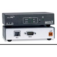
- Safety Instructions • English
- Caution
- Copyright
- Trademarks
- Contents
- Introduction ...... 1
- Installation and Operation .... 3
- Connection and Configuration .....11
- Communication and Control ....18
- Specifications, Part Numbers, and Accessories ....56
- Glossary 59
- Introduction
- About this Manual
- About the IPL T SFI244 Interface
- Features
- Easily configured and controlled —
- Installation and Operation
- Installation Overview
- Mounting the IPL T SFI244 Interface
- UL Guidelines for Rack Mounting
- Rack Mounting
- Furniture or Projector Mounting
- Rear Panel Features and Cabling
- Power
- Ethernet/LAN
- Serial Communication
- Identification
- Operation
- Front Panel Indicators
- Resetting the Unit
- Connection and Configuration
- Connecting the Hardware
- Ethernet Connection
- Serial Connection
- IR Connection
- Flex I/O Connection
- Configuring the Hardware
- PC Configuration
- Initial start up
- IPL T SFI244 Interface Configuration
- Configuring the IPL T SFI244 using the ARP command
- Configuring the IPL T SFI244 using direct PC connection
- Firmware upgrades
- Communication and Control
- Ports Overview
- Flex I/O Ports
- Digital input
- Digital output
- Analog input
- Bidirectional Serial Control Interface Ports
- Communication with the Interface
- Web Server
- Accessing and using the Web server
- Establishing or changing system or port settings
- Controlling IR devices or sending IR commands
- Setting and changing your passwords
- Editing and adding e-mail alerts
- Sending an e-mail alert through Telnet
- Upgrading the firmware
- Managing files
- IR Learning
- Creating a driver with the IR Learner software
- Programmer's Guide for the Telnet and Web Browser
- Using the Command/Response Table
- Symbol definitions
- Copyright information
- Password information
- Error responses
- References to errors (at command descriptions on the following pages)
- NOTE:
- Customization
- Server Side Includes
- SIS command types and syntax
- Query String
- Query string command types and syntax
- Code Examples
- Example 1
- HTML Example #1
- Example 2
- Example 3
- Example 4
- Example 5
- Example 6
- URL Encoding
- Reserved characters
- Unsafe characters
- A/V Device Control
- Custom Web Pages
- Telnet (Port 23)
- Accessing and using Telnet
- Direct Port Access (Ports 2001 Through 2002)
- Using direct access
- Port redirect
- Troubleshooting
- Power connections
- Data connections
- Specifications, Part Numbers, and Accessories
- Specifications
- Ethernet control interface
- Serial control interface
- Flex I/O control interface
- IR control interface
- General
- Part Numbers and Accessories
- Glossary
- Extron® Warranty
- USA, Canada, South America, and Central America:
- Japan:
- Europe, Africa, and the Middle East:
- China:
- Asia:
- Middle East:
Brand : Extron
Model : IPL T SFI244
Category : Network Interface