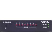
EXB-REL8 - Electronic control box AMX - Free user manual and instructions
Find the device manual for free EXB-REL8 AMX in PDF.


| Product Type | ICSLan Relay Interface, 8 Channels |
| Model Number | EXB-REL8 (FG2100-20) |
| Dimensions (H x W x D) | 1.00" x 4.35" x 5.15" (25.48 x 110.36 x 130.81 mm) |
| Weight | 1 lb (454 g) |
| Power Requirements | Power over Ethernet (PoE) |
| Power Draw (Idle) | 40 mA (1.92 W) |
| Power Draw (Max) | 70 mA (3.36 W) |
| Relay Outputs | 8 independent SPST relays, normally open |
| Relay Contact Rating | 1 A max @ 0-24 VAC or 0-28 VDC (resistive) |
| Network Interface | 10/100 BaseT Ethernet (RJ-45) with PoE |
| LED Indicators | 8 red relay status LEDs, green Status and L/A LEDs |
| Mounting Options | Surface mount, rack tray (up to 4 modules in 1U), or pole mount (kits sold separately) |
| Enclosure | Metal with black matte finish |
| Operating Temperature | 0°C to 40°C (32°F to 104°F) |
| Storage Temperature | -10°C to 60°C (14°F to 140°F) |
| Humidity | 5% to 85% RH (non-condensing) |
| Heat Dissipation | Up to 3.36 W (11.47 BTU/hr) |
| Certifications | FCC Part 15 Class B, CE, IEC 60950 |
| Compliance | UL 60950-1 2nd edition (when powered by listed LPS PoE source) |
| Front Panel Components | ID Pushbutton (for addressing and factory reset), Status LED, L/A LED |
| Rear Panel Connectors | Ethernet/PoE port (RJ-45), two 8-pin 3.5 mm Phoenix relay connectors |
| Included Accessories | Two 8-pin 3.5 mm Phoenix female relay connectors, one 8-position commoning strip |
| NetLinx Programming | Supports SEND_COMMANDs: LED-DIS, LED-EN, REBOOT, SET_NDX_DESC |
| Telnet Support | Yes, default port 23 (can be disabled) |
| Firmware Upgrade | Via NetLinx Studio using a .kit file |
| Maintenance | Clean with dry cloth; no user-serviceable parts inside |
Frequently Asked Questions - EXB-REL8 AMX
User questions about EXB-REL8 AMX
0 question about this device. Answer the ones you know or ask your own.
Ask a new question about this device
Download the instructions for your Electronic control box in PDF format for free! Find your manual EXB-REL8 - AMX and take your electronic device back in hand. On this page are published all the documents necessary for the use of your device. EXB-REL8 by AMX.
USER MANUAL EXB-REL8 AMX
IMPORTANT SAFETY INSTRUCTIONS
-
READ these instructions.
-
KEEP these instructions.
-
HEED all warnings.
-
FOLLOW all instructions.
-
DO NOT use this apparatus near water.
-
CLEAN ONLY with dry cloth.
-
DO NOT block any ventilation openings. Install in accordance with the manufacturer's instructions.
-
DO NOT install near any heat sources such as radiators, heat registers, stoves, or other apparatus (including amplifiers) that produce heat.
-
DO NOT defeat the safety purpose of the polarized or grounding type plug. A polarized plug has two blades with one wider than the other. A grounding type plug has two blades and a third grounding prong. The wider blade or the third prong are provided for your safety. If the provided plug does not fit into your outlet, consult an electrician for replacement of the obsolete outlet.
-
PROTECT the power cord from being walked on or pinched, particularly at plugs, convenience receptacles, and the point where they exit from the apparatus.
-
ONLY USE attachments/accessories specified by the manufacturer.

-
USE ONLY with a cart, stand, tripod, bracket, or table specified by the manufacturer, or sold with the apparatus. When a cart is used, use caution when moving the cart/apparatus combination to avoid injury from tip-over.
-
UNPLUG this apparatus during lightning storms or when unused for long periods of time.
-
REFER all servicing to qualified service personnel. Servicing is required when the apparatus has been damaged in any way, such as power-supply cord or plug is damaged, liquid has been spilled or objects have fallen into the apparatus, the apparatus has been exposed to rain or moisture, does not operate normally, or has been dropped.
-
DO NOT expose this apparatus to dripping or splashing and ensure that no objects filled with liquids, such as vases, are placed on the apparatus.
-
To completely disconnect this apparatus from the AC Mains, disconnect the power supply cord plug from the AC receptacle.
-
Where the mains plug or an appliance coupler is used as the disconnect device, the disconnect device shall remain readily operable.
-
DO NOT overload wall outlets or extension cords beyond their rated capacity as this can cause electric shock or fire.

The exclamation point, within an equilateral triangle, is intended to alert the user to the presence of important operating and maintenance (servicing) instructions in the literature accompanying the product.

The lightning flash with arrowhead symbol within an equilateral triangle is intended to alert the user to the presence of uninsulated "dangerous voltage" within the product's enclosure that may be of sufficient magnitude to constitute a risk of electrical shock to persons.

ESD Warning: The icon to the left indicates text regarding potential danger associated with the discharge of static electricity from an outside source (such as human hands) into an integrated circuit, often resulting in damage to the circuit.
WARNING: To reduce the risk of fire or electrical shock, do not expose this apparatus to rain or moisture.
WARNING: No naked flame sources - such as candles - should be placed on the product.
WARNING: Equipment shall be connected to a MAINS socket outlet with a protective earthing connection.
WARNING: To reduce the risk of electric shock, grounding of the center pin of this plug must be maintained.
COPYRIGHT NOTICE
AMX© 2015, all rights reserved. No part of this publication may be reproduced, stored in a retrieval system, or transmitted, in any form or by any means, electronic, mechanical, photocopying, recording, or otherwise, without the prior written permission of AMX. Copyright protection claimed extends to AMX hardware and software and includes all forms and matters copyrightable material and information now allowed by statutory or judicial law or herein after granted, including without limitation, material generated from the software programs which are displayed on the screen such as icons, screen display looks, etc. Reproduction or disassembly of embodied computer programs or algorithms is expressly prohibited.
LIABILITY NOTICE
No patent liability is assumed with respect to the use of information contained herein. While every precaution has been taken in the preparation of this publication, AMX assumes no responsibility for error or omissions. No liability is assumed for damages resulting from the use of the information contained herein. Further, this publication and features described herein are subject to change without notice.
AMX WARRANTY AND RETURN POLICY
The AMX Warranty and Return Policy and related documents can be viewed/downloaded at www.amx.com.
Table of Contents
ICSLan Device Control Boxes 8
Overview 8
Common Features 9
LAN/PoE Port 10
Detailed LED Behavior 10
Installation 12
Mounting Options (Rack Trays and Mounting Brackets) 12
AVB-VSTYLE-SURFACE-MNT (FG1010-722) 12
AVB-VSTYLE-RMK (FG1010-720) 12
AVB-VSTYLE-RMK-FILL-1U (FG1010-721).... 12
AVB-VSTYLE-POLE-MNT (FG1010-723) 13
SAFETY INSTRUCTIONS 13
Preparing/Connecting Captive Wires 13
LAN/PoE Port 13
Network Configuration 14
Overview 14
Default Parameters For Static IP Mode 14
DHCP Mode 14
TCP/IP Address Configuration.... 14
Telnet IP Configuration Commands 14
Master Connection Modes.... 15
TCP vs. UDP 15
URL vs. NDP vs. Auto 15
Factory Default Parameters 16
Device IDs.... 17
Using the ID Pushbutton 17
Using "Identify Mode" to Set the Device Address on the EXB Modules 17
Toggling Between Static and DHCP IP Addressing 18
Performing a Factory Reset.... 18
Resetting the Unit to the Factory Default Firmware Image 18
Programming the EXB Modules.... 19
EXB-COM2 20
Overview 20
EXB-COM2 Product Specifications.... 20
Connections and Wiring 21
LAN/PoE Port (RJ45) 21
Port 1 (Multi-Protocol COM Port) 21
Port 2 (RS-232 only) 21
Table of Contents
| NetLinx Programming | 21 |
| EXB-COM2 Port Assignments | 21 |
| EXB-COM2 SEND_COMMANDs | 22 |
| SEND_STRING Escape Sequences | 22 |
| Telnet commands | 22 |
| EXB-I/O8 | 23 |
| Overview | 23 |
| EXB-I/O8 Product Specifications | 23 |
| Connections and Wiring | 24 |
| LAN/PoE Port (RJ45) | 24 |
| Port 1 (I/O 1-8) | 24 |
| NetLinx Programming | 25 |
| EXB-I08 Port Assignments | 25 |
| EXB-I08 Channel Assignments | 25 |
| EXB-I/O8 SEND_COMMANDs | 25 |
| Telnet commands | 25 |
| EXB-IRS4 | 26 |
| Overview | 26 |
| EXB-IRS4 Product Specifications | 26 |
| Connections and Wiring | 27 |
| LAN/PoE Port (RJ45) | 27 |
| IR/Serial Port Bank (Ports 1-4) | 27 |
| Input Port Bank | 27 |
| Input Linking | 27 |
| Unlinked Mode (Default) | 27 |
| Linked Mode | 27 |
| Input Pin | 27 |
| Entering/Exiting Linked Mode | 27 |
| Linked Modes | 28 |
| NetLinx Programming | 29 |
| EXB-IRS4 Port Assignments | 29 |
| EXB-IRS4 Channel Assignments | 29 |
| EXB-IRS4 SEND_COMMANDs | 29 |
| Telnet commands | 29 |
| EXB-MP1 | 30 |
| Overview | 30 |
| EXB-MP1 Product Specifications | 30 |
| Connections and Wiring | 31 |
| LAN/PoE Port (RJ45) | 31 |
| Port 1 (RS-232 only) | 31 |
| Port 2 (I/O) | 31 |
Table of Contents
Port 3 (IR-TX/Serial) 31
Port 4 (IR-RX).... 31
NetLinx Programming 32
EXB-MP1 SEND_COMMANDs 32
SEND_STRING Escape Sequences 32
Telnet commands 32
EXB-REL8 33
Overview 33
EXB-REL8 Product Specifications 33
Connections and Wiring 34
LAN/PoE Port (RJ45) 34
Port 1 (Relay Connector).... 34
NetLinx Programming 34
EXB-REL8 Port Assignments 34
EXB-REL8 Channel Assignments 34
EXB-REL8 SEND_COMMANDs 34
Telnet commands 34
NetLinx Send Commands 35
B9MOFF 35
B9MON 35
CAROFF 35
CARON 35
CH 36
CHARD 36
CHARDM....36
CP 36
CTOF 37
CTON 37
CTSPSH 37
CTSPSH OFF 37
ESCSEQOFF 37
ESCSEQON 37
GET BAUD 38
GET DBT 38
GET INPUT 38
GET MODE 38
GET OFF DELAY 38
GET ON DELAY 38
HSOFF 38
HSON....39
IROFF 39
LED-DIS 39
LED-EN 39
POD 39
POF 39
PON 40
PTOF 40
PTON 40
REBOOT 40
RXCLR 41
RXOFF 41
RXON 41
SET BAUD 41
SET DBT 41
SET DBTF 42
SET INPUT 42
Table of Contents
| SET INPUT LINK | 42 |
| SET IO LINK | 42 |
| SET MODE | 42 |
| SET_NDX_DESC | 42 |
| SET OFF DELAY | 43 |
| SET ON DELAY | 43 |
| SP | 43 |
| TSET BAUD | 43 |
| TXCLR | 43 |
| XCH | 44 |
| XCHM | 44 |
| XOFF | 44 |
| XON | 44 |
SEND\_STRING Escape Sequences.... 45
27,17 45
27,18,0 45
27,18,1 45
27,19 45
27,20,0 45
Appendix A: Terminal (Telnet) Commands 46
Overview 46
Establishing a Terminal Connection via Telnet 46
Telnet Username and Password 46
Additional Notes 46
Setting a Telnet Username and Password 47
Telnet Commands 47
? or Help.... 47
DEVICE STATUS 47
EXIT 47
FACTORYFWIMAGE 47
GET CONFIG 48
GET CONNECTION.... 48
GET DEVICE.... 48
GET DNS 48
SET TELNET PASSWORD 51
SHOW CONNECTION LOG.... 51
SHOW CONNECTION STATS.... 51
Notes on Specific Telnet Clients.... 52
Windows Client Programs 52
Linux Telnet Client 52
Table of Contents
| Enabling / Disabling Telnet on EXB Modules | 52 |
| SHOW LOG | 52 |
| Appendix B: Upgrading Firmware | 53 |
| Firmware Upgrades | 53 |
| Downloading the Latest Firmware from www.amx.com | 53 |
| Upgrading Firmware via NetLinx Studio | 53 |
| Identifying the Current Firmware Version of the EXB Unit | 53 |
| Transferring a Firmware File to an EXB Unit | 54 |
ICSLan Device Control Boxes
Overview
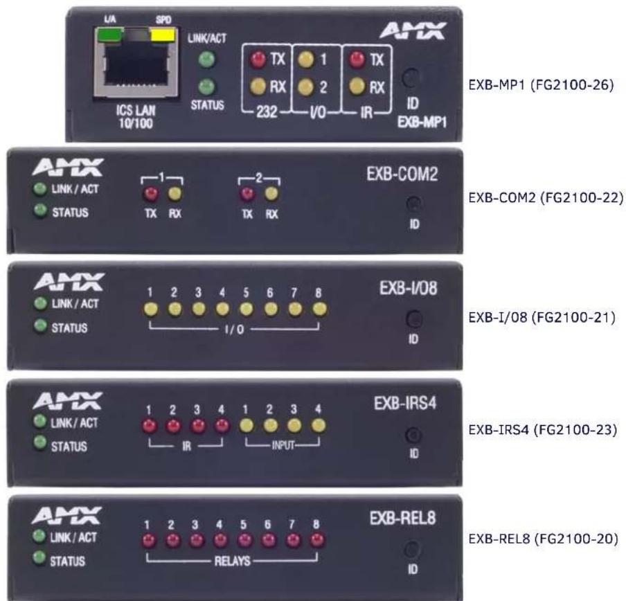
The EXB family of ICSLan Device Control Boxes (FIG. 1) provides Ethernet-based remote port expansion for NetLinx Central Controllers. ICSLan Device Control Boxes may be used to provide remote ports for a master (eliminating the need to implement another Central Controller), or to provide large numbers of ports in a rack-mount environment.
EXB-MP1 (FG2100-26)
FIG. 1 ICSLan Device Control Boxes
| ICSLan Device Control Boxes - Product Family | |||
| Name FG# Description Page Reference | |||
| EXB-COM2 FG2 | 100-22 ICSLan | Serial Interface, 2 Ports See page 20 | |
| EXB-I/08 | FG2100-21 | ICSLan Input/Output Interface, 8 Channels | See page 23 |
| EXB-IRS4 | FG2100-23 | ICSLan IR/S Interface, 4 IR/S and 4 Inputs | See page 26 |
| EXB-MP1 FG21 | 00-26 ICSLan M | Multi-Port, 1 COM, 1 IR/S, 2 I/O, 1 IR RX See page 30 | |
| EXB-REL8 | FG2100-20 | ICSLan Relay Interface, 8 Channels | See page 33 |
Common Features
Many features are common to all products in the EXB family, as described in the following table. Model-specific features are described in the following sections.
| ICSLan Device Control Boxes - Common Features | ||
| Dimensions (HWD): • EXB-COM2: -I/08, -IRS4 and -REL8:1.00" x 4.35" x 5.15" (25.48 x 110.36 x 130.81)• E X B - M P 1 :1.00" x 3.04" x 4.82" (25.48cm x 77.14cm x 122.43cm) | ||
| Weight: • EXB-COM2: 1 lb (454 g)• EXB-I/08: 1 lb (454 g)• EXB-IRS4: 1 lb (454 g)• E X B - M P 1 : 1 lb ( 4 5 4 g )• EXB-REL8: 1 lb (454 g) | ||
| Power Requirements: PoE (Power-over-Ethernet). | ||
| ExB-COM2: 40mA 1.92 watts 40mA 1.92 watts | ||
| EXB-I08: 30mA 1.44 watts 40mA 1.92 watts | ||
| EXB-IRS4: 40mA 1.92 watts 50mA 2.4 watts | ||
| EXB-MP1 40mA 1.92 watts 40mA 1.92 watts | ||
| EXB-REL8: 40mA 1.92 watts 70mA 3.36 watts | ||
| Enclosure: Metal with black matte finish | ||
| Front Panel Components | ||
| ID Pushbutton: | The ID Pushbutton serves four functions:• ID Mode: Used in conjunction with the ID Mode feature in NetLinx Studio, a momentary push assigns a device address to the Module. See the Using "Identify Mode" to Set the Device Address on the EXB Modules section on page 17 for details.• Static/DHCP: If the button is pressed and held for 10 seconds or longer and then released, the unit toggles between static and dynamic IP addressing. See the Toggling Between Static and DHCP IP Addressing section on page 18 for details.• Factory Reset: If the ID button is held for 10 seconds or longer during the boot process, the unit will reset to factory defaults. See the Performing a Factory Reset section on page 18 for details.• Factory Image: If the ID pushbutton is held for 20 seconds and released while the Module is booting up, the Module will restore itself to a factory firmware image. See the Resetting the Unit to the Factory Default Firmware Image section on page 18 for details. | |
| Status LED: | The green Status LED indicates unit status.See the Detailed LED Behavior section on page 10 for details. | |
| L/A LED: | The green L/A (Link / Active) LED indicates communication status.See the Detailed LED Behavior section on page 10 for details. | |
| Rear Panel Components | ||
| Ethernet / PoE Connector | RJ-45 connector provides IP communication and PoE.This is an Auto MDI/MDI-X enabled port, therefore either straight-through or crossover Ethernet cables can be used.NOTE: The Ethernet connector is located on the front panel of the EXB-MP1 (see FIG. 9 on page 30). | |
| Module Specific Connectors | Varies per model - refer to Connections and Wiring in each of the following sections. | |
| Storage/Operating Environment: | • Operating Temperature: 0°C (32°F) to 40°C (104°F)• Storage Temperature: -10°C (14°F) to 60°C (140°F)• Operating Humidity: 5% to 85% RH (non-condensing)• Heat Dissipation (Typical): 36.9 BTU/hr• Designed for indoor use only. | |
| Certifications: | FCC Part 15 Class B, CE, and IEC 60950 | |
| Included & Optional Accessories | Varies per model - refer to the Specifications tables In each of the following sections. | |
LAN/PoE Port
The LAN/PoE (RJ45) port on all EXB Modules provides 10/100 BaseT network connectivity. Use standard Cat5/6/6E ethernet cable to connect the EXB Module to the LAN. The following table lists the pinouts, signals, and pairing for the Network port.
| LAN/PoE Port Pinouts and Signals | ||||
| Pin Signals Connections Pairing Color | ||||
| 1 TX | + 1 ---- 1 1 ---- 2 White-Orange | |||
| 2 TX | - 2 ---- 2 Orange | |||
| 3 RX | + 3 ---- 3 3 ---- 6 White-Green | |||
| 4 | no connection | 4 ---- 4 | Blue | |
| 5 | no connection | 5 ---- 5 | White-Blue | |
| 6 RX | - 6 ---- 6 | Green | ||
| 7 | no connection | 7 ---- 7 | White-Brown | |
| 8 | no connection | 8 ---- 8 | Brown | |
The Ethernet Port LEDs show communication activity, connection status, speeds, and mode information:
- SPD (speed) - Yellow LED lights On when the connection speed is 100 Mbps and turns Off when the speed is 10 Mbps.
- L/A (link/activity) - Green LED lights On when the Ethernet cables are connected and terminated correctly, and blinks when receiving Ethernet data packets.
Detailed LED Behavior
The table below provides detailed descriptions of all blink patterns for the Status and A/L LEDs on the front panels of all EXB Modules.
- The I/O LED column refers to port-specific Input and/or Output LEDs on a particular model. For example, I/O includes all serial TX and RX LEDs on a COM2 or all Relay output LEDs on a REL8.
- The term "Light Show" refers to the back-and-forth scanning pattern of the LEDs associated with the I/Os on each model.
| EXB Modules - Detailed LED Behavior | |||
| Module Condition | L/A LED | Status LED | I/O LED |
| Normal Online with Master (rest) | On if connected to master. Blink off w/ data. | Follow Master's instruction for Blink Message if online with Master, otherwise ON | On when active, otherwise off |
| Normal Boot (DHCP found)NOTE: This state continues from the time on IP address is obtained until the device is online with the Master. | OFF | ON | Normal Light Show, then OFF until online with Master, then normal operation |
| Normal Boot (DHCP, no server)NOTE: This state continues until a valid IP address is obtained. | Fast Blink, then normal operation | ON | Normal Light Show, then OFF until online with Master, then normal operation |
| Normal Boot (Static IP)NOTE: This state continues until the device finishes the Light Show. | OFF during Light Show, then normal operation (Off until connected to Master) | Fast Blink (continues only during Light Show), then ON until first blink from Master. | Normal Light Show, then OFF until online with Master, then normal operation |
| Boot with ID Pushbutton held down | Slow Blink (1Hz) | Slow Blink (1Hz) | Slow Blink (1Hz) |
| ID Pushbutton held down long enough for reset to default parameters | Fast Blink until ID Pushbutton is released, then OFF | Fast Blink until ID Pushbutton is released, then OFF | Fast Blink until ID Pushbutton is released, then OFF |
| ID Pushbutton held down long enough for reset to default firmware image | Solid ON, transitions to OFF once the unit completes writing to flash and is ready to reboot | Solid ON, transitions to OFF once the unit completes writing to flash and is ready to reboot | Solid ON, transitions to OFF once the unit completes writing to flash and is ready to reboot |
| In Auto ID mode | Normal | Blink (2Hz) | Normal |
| ID Pushbutton held down long enough to accept new ID | 2 Blinks, then normal | 2 Blinks, then normal | 2 Blinks, then normal |
| After boot: ID Pushbutton held down, but not long enough for IP mode change | Slow Blink (1Hz) | Slow Blink (1Hz) | Slow Blink (1Hz) |
| EXB Modules - Detailed LED Behavior (Cont.) | |||
| Module Condition L/A LED Status | LED I/O LED | ||
| After boot: ID Pushbutton held down long enough for IP mode change | Fast Blink, then OFF Fast Blink, then | OFF Fast Blink, then OFF | |
| Downloading Firmware to Flash Due to an upgrade via NetLinx Studio. | Fast Blink, alternating with Status LED) | Fast Blink, alternating with L/A LED) | Fast Blink, alternating LEDs |
See the Using the ID Pushbutton section on page 17 for additional information.
Installation
Mounting Options (Rack Trays and Mounting Brackets)
Refer to the documentation provided with each of the mounting kits for installation instructions (also available online at www.amx.com).
AVB-VSTYLE-SURFACE-MNT (FG1010-722)
V Style Single Module Surface Mount Brackets - Mount a single module to the wall, under a desk, etc (FIG. 2).
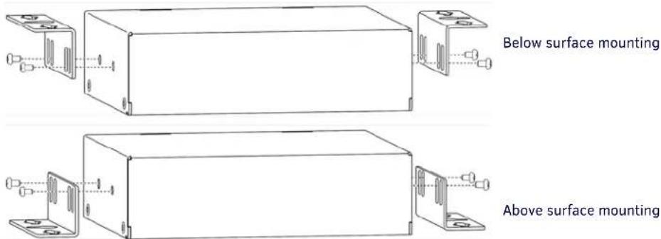
FIG. 2 AVB-VSTYLE-SURFACE-MNT
AVB-VSTYLE-RMK (FG1010-720)
V Style Module Tray Rack - Mount up to four modules side by side in a 1 RU space (FIG. 3).
AVB-VSTYLE-RMK-FILL-1U (FG1010-721)
V Style Module Tray Rack - Mount up to four modules side by side in a 1 RU space, with Fill Plates for instances when the entire tray is not full (FIG. 3).
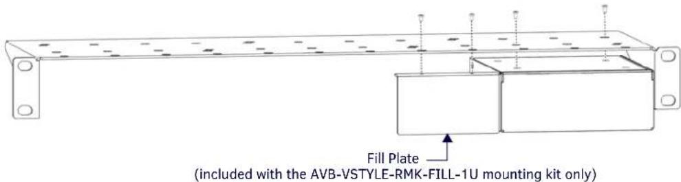
FIG. 3 AVB-VSTYLE-RMK
Note that the tray illustrated in FIG. 3 is shown upside down for ease of installation. However, the tray can be rack-mounted in a rack either way.
Also note that the Fill Plate included in this illustration is included only in the AVB-VSTYLE-RMK-FILL-1U (FG1010-721).
NOTE: The AVB-VSTYLE-RMK and AVB-VSTYLE-RMK-FILL-1U mounting kits are appropriate for the EXB-COM2, -IRS4, -IO8 and -REL8 (but not the EXB-MP1).
AVB-VSTYLE-POLE-MNT (FG1010-723)
V Style Single Module Pole Mounting Kit - Suspend a single module to a pole (FIG. 4).
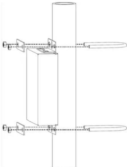
natural_image
Pure mechanical assembly diagram showing a vertical cylindrical component connected to two horizontal plates with mounting holes (no text or symbols)FIG. 4 AVB-VSTYLE-POLE-MNT
SAFETY INSTRUCTIONS
- For UL compliance, the EXB family of ICSLan Device Control Boxes should be powered directly via any listed external IEC/UL 60950-1 2nd edition certified LPS PoE switch or injector, such as the AMX NXA-ENET8POE or PS-POE-AF.
- The EXB family of ICSLan Device Control Boxes are intended for Network Environment 0 per IEC TR62101, and are to be connected only to PoE networks without routing to the outside plant.
Preparing/Connecting Captive Wires
- Strip 0.25 inch of wire insulation off all wires.
- Insert each wire into the appropriate opening on the connector according to the wiring diagrams and connector types described in this section.
Do not tighten the screws excessively; doing so may strip the threads and damage the connector.
LAN/PoE Port
The LAN/PoE (RJ45) port on all EXB Modules provides 10/100 BaseT network connectivity. Use standard Cat5/6/6E ethernet cable to connect the EXB Module to the LAN. The following table lists the pinouts, signals, and pairing for the Network port.
| LAN/PoE Port Pinouts and Signals | ||||
| Pin Signals Connections Pairing Color | ||||
| 1 TX + 1 ---- 1 1 ---- 2 White-Orange | ||||
| 2 | TX - | 2 ---- 2 | Orange | |
| 3 RX + 3 ---- 3 | 3 ---- 6 White-Green | |||
| 4 | DC + | 4 ---- 4 | Blue | |
| 5 | DC + 5 ---- 5 | White-Blue | ||
| 6 | RX - | 6 ---- 6 | Green | |
| 7 | DC - | 7 ---- 7 | White-Brown | |
| 8 | DC - | 8 ---- 8 | Brown | |
The Ethernet Port LEDs show communication activity, connection status, speeds, and mode information:
- SPD (speed) - Yellow LED lights On when the connection speed is 100 Mbps and turns Off when the speed is 10 Mbps.
- L/A (link/activity) - Green LED lights On when the Ethernet cables are connected and terminated correctly, and blinks when receiving Ethernet data packets.
Network Configuration
Overview
EXB modules support two IP addressing modes: Static IP, and DHCP (with link-local fallback).
NOTE: "Link-Local Fallback" is a method by which an IP host can derive a local network-unique IP address, by negotiating with the other IP hosts on the same network, as a fallback from DHCP. Link-Local can also be used in its own right as the primary method of IP address allocation. See "DHCP Mode" below for details.
By default, EXB Modules are set to DHCP Mode.
The modules can be configured for either of these modes via two methods:
- The front-panel ID Pushbutton (see the Toggling Between Static and DHCP IP Addressing on page 18).
- Telnet command (see the Appendix A: Terminal (Telnet) Commands on page 46).
Default Parameters For Static IP Mode
| Default Parameters For Static IP Mode | |
| Address: 192.168.1.2 | |
| Netmask: 255.255.255.0 | |
| Gateway: | 192.168.1.1 |
| DNS1: 192.168.1.1 | |
| DNS2: 192.168.1.1 | |
| DNS3: 192.168.1.1 | |
DHCP Mode
When in DHCP mode (the default setting), the module will attempt to get a DHCP lease (consisting of IP address, gateway, and other network parameters). Should it fail to obtain a lease from a DHCP server, it will then configure itself for a link-local address.
- EXB modules utilize a modified link-local addressing procedure: the first address to be tried is a known address in the link-local space: 169.254.2.2. That address will be probed, and if unclaimed will be used by the EXB module.
- If 169.254.2.2 is already claimed, the EXB module will choose a random address within the 169.252.x.x link-local address space (again probing to ensure that it is unclaimed).
Once operating with a link-local address, the device will periodically re-try DHCP, and re-assign the IP to a valid DHCP grant if successful.
At any time, if the device determines that its IP address has changed, it will disconnect from the Master (if necessary, depending on the connection state), and then reconnect to the Master.
TCP/IP Address Configuration
EXB modules support IPV4 network addresses, gateway addresses, DNS server addresses, and network name. EXB modules support NetLinx Discovery Protocol (NDP) capabilities as well as IP discovery via NetLinx Studio.
NOTE: NDP stands for "NetLinx Discovery Protocol", a device discovery method used by NetLinx Masters. With NDP Beacon enabled, the Master will transmit NDP beacons for AMX's proprietary device discovery.
Telnet IP Configuration Commands
The SET IP (page 51) and GET IP (page 49) Telnet commands listed in the following table can be sent directly to the device via a Telnet terminal session. These commands can be used for initial network configuration of the EXB Modules.
- The default Telnet port is 23. A value of 0 disables the telnet server.
- Telnet is enabled by default.
- See the Appendix A: Terminal (Telnet) Commands section on page 46 for details.
Master Connection Modes
The mode of communication used for connection to the Master is specified via the SET CONNECTION Telnet command (see page 49).
The options are "AUTO", "URLTCP", "URLUDP" or "NDP", as described below.
Note that default connection mode setting is NDP.
- AUTO - This mode utilizes TCP communication; it looks for a matching System Number and attempts to come online with the first master it sees with that System Number.
- URLTCP - TCP; the Master is specified via URL.
- URLUDP - UDP; the Master is specified via URL.
- NDP - UDP; this mode utilizes the NDP binding process to assign the EXB Module (the physical device) to a Master via NetLinx Studio. Once bound, communications are conducted via UDP.
NOTE: In URL modes, the Master can use either an IP address or a DNS name.
TCP vs. UDP
- TCP - Protocol has built-in retry mechanism.
- UDP - Protocol does not have a built-in retry mechanism, but consumes fewer resources on the Master. AMX's UDP implementation of NetLinx employs a retry mechanism to provide the reliability of TCP, with the resource efficiency of UDP.
URL vs. NDP vs. Auto
Determining which connection method to use for Master Connection Mode is essentially a matter of deciding what information the device should use to identify the correct target Master for connection.
The default mode is NDP; the mode can be changed via the SET CONNECTION Telnet command (see page 49).
- URL - The device connects to the Master with the specified URL. The device must be configured with the URL of a specific Master via the SET CONNECTION Telnet command (see page 49).
- NDP - The device connects to the Master it's been bound to based on the Masters MAC address. The binding is configured via NetLinx Studio. Once bound, the device must be unbound using either NetLinx Studio or the Telnet NDP UNBIND command before being re-bound to a different Master.
Alternatively, NDP devices can be bound/unbound via options on the Master's Web Configuration pages (System > Manage NetLinx). Refer to the NetLinx Integrated Controllers- WebConsole & Programming Guide (System - Manage NetLinx section) for details.
- Auto - The device connects to the first Master it finds with the specified System Number. The device must be configured with the desired system number via the SET CONNECTION Telnet command (see page 49).
Use of this method requires that only one Master has any particular system number, and is visible to the subnet. If this is the case, then Auto is the most simple choice. However, with Auto, you are not hard-bound to a particular Master.
Therefore, if at some point in the future, another Master is configured with the same system number, the result is that the EXB Module could show up on that other Master.
Factory Default Parameters
Factory Default Parameters are the values stored in the unit at the time it leaves the factory. EXB Modules can be restored the unit to their factory default parameters in several ways:
- via the ID Pushbutton (see the Performing a Factory Reset section on page 18)
- via the RESET FACTORY telnet command (see page 49)
The factory default parameters are listed below:
| Factory Default Parameters | |
| Parameter Value | |
| MAC Address As set in factory | |
| Serial Number As set in factory | |
| Ethernet mode Auto (i.e., speed, duplex, both, auto) | |
| IP Addressing Mode DHCP | |
| IP Address (for static mode) 192.168.1.2 | |
| Netmask (for static mode) 255.255.255.0 | |
| Gateway (for static mode) 192.168.1.1 | |
| DNS1 (for static mode) 192.168.1.1 | |
| DNS2 (for static mode) 192.168.1.1 | |
| DNS3 (for static mode) 192.168.1.1 | |
| DNS Domain amx.com | |
| Hostname | Last seven digits of the model-serial number - unique for each unitNote: Host names may contain only the ASCII letters 'a' through 'z' (case-insensitive), the digits '0' through '9', and the hyphen ('-'). |
| Master Connection Mode | NDP - See the Master Connection Modes section on page 15 for details. |
| Master URL (for TCP and UDP URL modes) | "" (blank) |
| Master Connection port number for TCP and UDP URL modes | 1319 |
| Friendly-Name | "" (blank)Note: If the Friendly Name is non-blank, both Friendly Name and Location are concatenated to make NDPSTRING2, otherwise NDPSTRING2 is generated from the unit's serial number. |
| Location | "" |
| Stored MAC address of Master (used for NDP binding) | 00:00:00:00:00:00 |
| ICSP Device Number | 0 (receive dynamic device number from Master) |
| System Number | 0 |
| Username for Master | Blank (empty string)A blank username and password implies that no encryption will be used |
| Password for Master | Blank (empty string)A blank username and password implies that no encryption will be used |
| Telnet port | 23A value of 0 disables the telnet server. Telnet is enabled by default. |
| Telnet username | Blank (empty string)A blank username and password implies that the telnet server will not query for username password |
| Telnet password | Blank (empty string) |
| CTOF time | 5 (0.5 seconds) |
| CTON time | 5 (0.5 seconds) |
| Baud Data Rate/Format | 9600, 8, N, 1 |
Device IDs
| Device IDs | |
| Model ID (16-bits) | |
| EXB-COM2 0x0164 | |
| EXB-I/08 0x0168 | |
| EXB-IRS4 0x0166 | |
| EXB-MP1 0x0165 | |
| EXB-REL8 0x0167 | |
Using the ID Pushbutton
Use the ID Pushbutton (on the front panel of all EXB Modules) to perform various initial configuration settings, as described in the following sections. The ID Pushbutton provides several functions, depending on when and for how long the pushbutton is pressed and held:
- Momentary press: If the device is in ID mode, a momentary press causes the module to identify itself to the system. Note that a momentary press at any other time is ignored.
See the Using "Identify Mode" to Set the Device Address on the EXB Modules section (below) for details.
- 10-Second Press and Hold (during runtime): If the ID Pushbutton is held for 10 seconds or longer and then released during runtime (i.e., after boot completes), the unit will toggle between Static IP and DHCP Mode IP addressing - after the button is released.
Note that after applying the new setting, the module will automatically reboot.
By default, EXB Modules are set to DHCP Mode (with link-local fallback).
See the Toggling Between Static and DHCP IP Addressing section on page 18 for details.
- 10-Second Press and Hold (during boot-up): If the ID Pushbutton is held for 10 seconds or longer at boot, the module will reset to factory default parameters and reboot after release.
Press and hold the ID Pushbutton while plugging in the Ethernet / PoE connector. Begin counting only when the LEDs begin to flash (as opposed to the moment that the connector is inserted).
Note that once the module has started booting up, all LEDs flash in unison at the rate of once per second. After 10 flashes at this rate, the LEDs will flash in unison at a faster rate. At the point that the blink rate increases (approximately 10 seconds after boot-up), release the pushbutton.
See the Performing a Factory Reset section on page 18 for details.
- 20-Second Press and Hold (during boot-up): If the ID Pushbutton is held for 20 seconds or longer at boot, the module will reset to the factory default firmware image and reboot after release.
Press and hold the ID Pushbutton while plugging in the Ethernet / PoE connector. Begin counting only when the LEDs begin to flash (as opposed to the moment that the connector is inserted).
Note that once the module has started booting up, all LEDs flash in unison at the rate of once per second. After 10 flashes at this rate, the LEDs will blink in unison at a faster rate. After 10 seconds of flashing at the increased rate, all LEDs go to solid on. At the point that the LEDs go to solid on (approximately 20 seconds after boot-up), release the pushbutton.
See the Resetting the Unit to the Factory Default Firmware Image section on page 18 for details.
Using "Identify Mode" to Set the Device Address on the EXB Modules
The ID Pushbutton on the front panel of all ICSLan Device Control Boxes is used in conjunction with the NetLinx Studio software application ("Identify Mode" function). Once the EXB Module has been added to a NetLinx System, you can use the ID pushbutton to identify and assign a device address to the Module.
EXB-COM2, -REL8, -I/O8, -IRS4 EXB-MP1
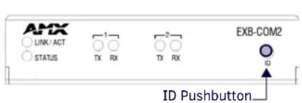
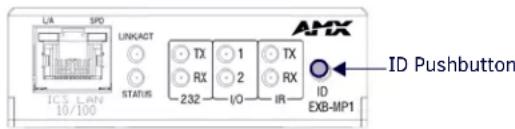
FIG. 5 ID Pushbutton Location
NOTE: The latest version of NetLinx Studio is available to download and install from the www.amx.com web site. Refer to the NetLinx Studio online help for instructions on using the application.
-
In NetLinx Studio, select the System to which the EXB Module is connected in the Online Device Tree.
-
Select Device Addressing from either the Online Device Tree context menu or the Diagnostics menu to open the Device Addressing dialog. The ID Mode section of the Device Addressing dialog allows you to place the program in ID (Identify) Mode. ID Mode means that the entire system is put on hold while it waits for an event from any NetLinx device in the named system (for example, pushing the ID pushbutton on the EXB Module). The device that generates the first event is the device that gets "identified".
Once a device has been identified, it will be set (or changed to) the Device/System Address specified.
NOTE: If the target Master has security applied, NetLinx Studio will prompt you for a User Name and Password in order to change these settings.
- In the ID Mode section of the dialog, enter the Device and System numbers that you want to assign to the Module, in the (Change to Device) Device and System text boxes.
NOTE: NetLinx Studio (v3.3 or higher) provides the ability to auto-increment IP Addresses and Hostnames as well as Device and System Numbers. Refer to the NetLinx Studio online help for details.
-
Click the Start Identify Mode button to place the named System in ID Mode. The text box below this button displays a Waiting...Press Cancel to Quit message. The Start Identify Mode button changes to Cancel Identify Mode (click to cancel ID Mode).
-
Press the ID button on the EXB Module. This causes the Module to:
-
Respond with an identify mode address response
• Report its old address offline
• Report its new address online
The Online Device Tree will refresh to represent the new device address.
Toggling Between Static and DHCP IP Addressing
EXB modules support both Static IP and DHCP addresses, and have a factory default Static IP Address that can be recalled at any time by resetting the unit to its default configuration.
By default, EXB Modules are set to use DHCP (with link-local fallback).
Once the Module has booted up, press and hold the ID pushbutton for at least 10 seconds, and release.
- The Module will toggle between static and dynamic IP addressing after release.
- The Module will automatically reboot to complete the process.
NOTE: EXB Modules can also be set to Static IP or DHCP Mode via the SET IP Telnet command (page 51). See the Appendix A: Terminal (Telnet) Commands section on page 46 for details.
Performing a Factory Reset
- Press and hold the ID Pushbutton while plugging in the Ethernet / PoE connector. Begin counting only when the LEDs begin to flash (as opposed to the moment that the connector is inserted).
NOTE: A press-and-hold of the ID Pushbutton at boot will prevent the Module from attempting to come online until the pushbutton is released. The Module will only attempt to come online if the hold time is less than 10 seconds.
Note that once the module has started booting up, all LEDs flash in unison at the rate of once per second. After 10 flashes at this rate, the LEDs will flash in unison at a faster rate.
-
At the point that the blink rate increases (approximately 10 seconds after boot-up), release the pushbutton.
-
The Module will automatically reboot to complete the process.
NOTE: When switching from Dynamic to Static IP using this method, the static IP address is set to the factory default IP Address, regardless of other static IP addresses that may have been set previously.
Resetting the Unit to the Factory Default Firmware Image
- Press and hold the ID Pushbutton while plugging in the Ethernet / PoE connector. Begin counting only when the LEDs begin to flash (as opposed to the moment that the connector is inserted).
Note that once the module has started booting up, all LEDs flash in unison at the rate of once per second. After 10 flashes at this rate, the LEDs will blink in unison at a faster rate.
After 10 seconds of flashing at the increased rate, all LEDs go to solid on.
-
At the point that the LEDs go to solid on (approximately 20 seconds after boot-up), release the pushbutton.
-
The Module will restore itself to a factory firmware image by performing the following actions:
a. Copy the boot code from the factory image to the boot block in flash memory.
b. Mark the boot parameter block in flash memory to indicate that the unit should boot from slot#0 (the factory application code slot).
c. Delete the application and boot code in flash memory slots #1 and #2.
d. Delete the IRL files stored on the Module.
While the button is held at boot (for at least 11 seconds), all LEDs on the Module continue to fast-blink.
- Once all writes to flash memory are completed, the LEDs will all be extinguished, indicating that the unit is ready to reboot.
- The Module will automatically reboot to complete the process.
Programming the EXB Modules
The EXB Modules support specific NetLinx CHANNELS, LEVELS and SEND_COMMANDs as well as a set of Telnet commands.
The CHANNELS, LEVELS and SEND_COMMANDs supported by each Module are described in the NetLinx Programming sections for each Module:
- EXB-COM2: See the NetLinx Programming section on page 21.
- EXB-REL8: See the NetLinx Programming section on page 34.
- EXB-I08: See the NetLinx Programming section on page 25.
- EXB-IRS4: See the NetLinx Programming section on page 29.
- EXB-MP1: See the NetLinx Programming section on page 32.
Refer to the Appendix A: Terminal (Telnet) Commands section on page 46 section for detailed descriptions of the Telnet commands (supported by all EXB Modules).
EXB-COM2
Overview
The EXB-COM2 Networked COM2 Device (FG2100-22) provides 2 serial ports: one RS-232/422/485 port, and one RS-232 (only) port.
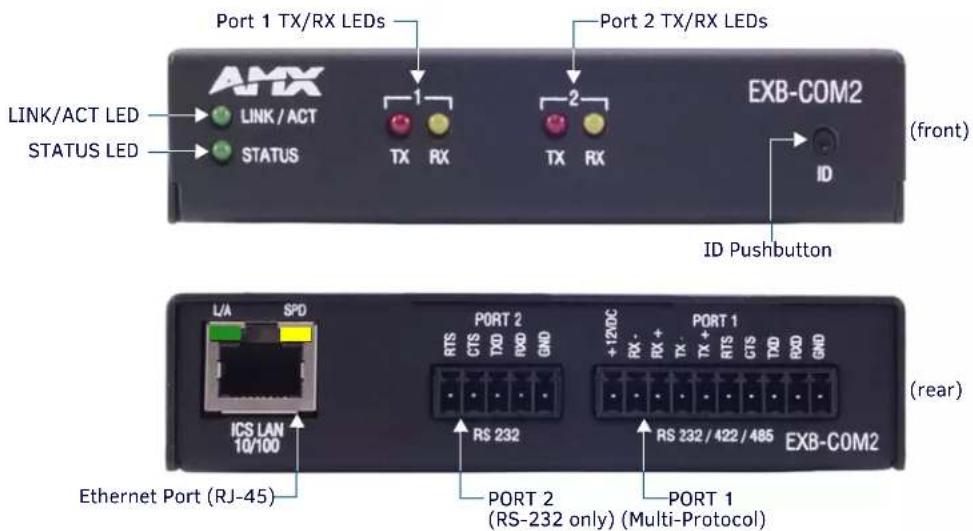
FIG. 6 EXB-COM2
EXB-COM2 Product Specifications
In addition to the features described in the ICSLan Device Control Boxes - Common Features table on page 9, the components and specifications listed below are specific to the EXB-COM2 module:
| EXB-COM2 Specifications | |
| Power Requirements | |
| PoE (Power-over-Ethernet) | |
| Power Draw • Idle (min): 40mA 1.92 watts | • Busy (max): 40mA 1.92 watts |
| Front Panel Components | |
| Port 1 TX/RX LEDs • Yellow (RX): indicates incoming activity on Port 1.• Red (TX): indicates outgoing activity on Port 1. | |
| Port 2 TX/RX LEDs • Yellow (RX): indicates incoming activity on Port 2.• Red (TX): indicates outgoing activity on Port 2. | |
| Rear Panel Components | |
| RS232 Port (Port 2) Connector: 3.5mm Phoenix – 5 position | |
| RS232/422/485 Port (Port 1) Connector: 3.5mm Phoenix – 10 position | |
| Included Accessories • 10-pin 3.5 mm mini-Phoenix (female) RS-232/422/485 connector (41-5107)• 5-pin 3.5 mm mini-Phoenix (female) RS-232 connector (41-0336) | |
| Other AMX Equipment | • NXA-ENET8POE Gigabit Ethernet Switch (FG2178-62)• PS-POE-AF PoE Injector (FG423-80)• AVB-VSTYLE-SURFACE-MNT V-Style Module Surface Mount (FG1010-722)• AVB-VSTYLE-RMK-1U V-Style Module Tray (FG1010-720)• AVB-VSTYLE-RMK-FILL-1U V-Style Module Tray w/ fill plates (FG1010-721)• AVB-VSTYLE-POLE-MNT V Style Module Pole Mount (FG1010-723) |
Connections and Wiring
LAN/PoE Port (RJ45)
The LAN/PoE (RJ45) port on the rear panel provides 10/100 BaseT network connectivity. This port is common to all EXB Modules. Use standard Cat5/6/6E ethernet cable to connect the EXB Module to the LAN.
Refer to the LAN/PoE Port section on page 13 for the pinout configuration for this port.
Port 1 (Multi-Protocol COM Port)
Port 1 (multi-protocol port) on the rear panel is a 10-pin 3.5mm captive-wire connector that supports RS-232/422/485 serial communication. The following table describes the pinout configuration of Port 1:
| EXB-COM2 Port 1 Pin Assignments | ||||||
| Wiring Conf iguration | ||||||
| Signal Function RS-232 RS-422 RS-485 | ||||||
| GND Signal ground X X | ||||||
| RXD Receive data X | ||||||
| TXD Transmit data X | ||||||
| CTS Clear to send X | ||||||
| RTS Request to send | X | |||||
| TX+ | Transmit data | X | X | (strap to pin 8) | 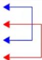 | |
| TX- | Transmit data | X | X | (strap to pin 9) | ||
| RX+ | Receive data | X | X | (strap to pin 6) | ||
| RX- | Receive data | X | X | (strap to pin 7) | ||
| +12 VDC | Power(Max current 200 mA) | optional | optional | |||
Port 2 (RS-232 only)
Port 2 on the rear panel is a 5-pin 3.5mm captive-wire connector that supports RS-232 (only) serial communication. Pins 1-5 on COM2 provide the same RS-232 functions as pins 1-5 on the COM1 connector:
| EXB-COM2 Port 2 Pin Assignments | |
| Signal | Function |
| GND | Signal ground |
| RXD | Receive data |
| TXD | Transm1 t data |
| CTS | Clear to send |
| RTS | Request to send |
NetLinx Programming
EXB-COM2 Port Assignments
| EXB-COM2 Port Assignments | |
| Port | Description |
| 1 | COM Port 1 |
| 2 | COM Port 2 |
EXB-COM2 SEND\_COMMANDs
The following NetLinx SEND_COMMANDs are supported by the EXB-COM2 Module:
| EXB-COM2 SEND_COMMANDs | |||
| Command Page Reference Command Page Reference | |||
| B9MOFF | page 35 | REBOOT | page 40 |
| B9MON | page 35 | RXCLR | page 41 |
| CHARD | page 36 | RXOFF | page 41 |
| CHARDM | page 36 | RXON | page 41 |
| CTSPSH | page 37 | SET BAUD | page 41 |
| CTSPSH OFF | page 37 | SET_NDX_DESC | page 42 |
| ESCSEQOFF | page 37 | TSET BAUD | page 43 |
| ESCSEQON | page 37 | TXCLR | page 43 |
| GET BAUD | page 38 | XOFF | page 44 |
| HSOFF | page 38 | XON | page 44 |
| HSON | page 39 | ||
| LED-DIS | page 39 | ||
| LED-EN | page 39 | ||
SEND\_STRING Escape Sequences
The EXB-COM2 and EXB-MP1 support several special SEND_STRING escape sequences. If any of the escape sequences are found anywhere within a SEND_STRING program instruction, they will be treated as a command and not the literal characters. See the SEND_STRING Escape Sequences section on page 45 for details.
Telnet commands
Refer to the Appendix A: Terminal (Telnet) Commands section on page 46 for a listing of all supported Telnet commands.
EXB-I/08
Overview
The EXB-I/O8 Networked 8-I/O Device (FG2100-21) provides eight Input/Output channels with LED feedback. It acts as a logic-level input and responds to switch closures or voltage level (high/ low) changes.
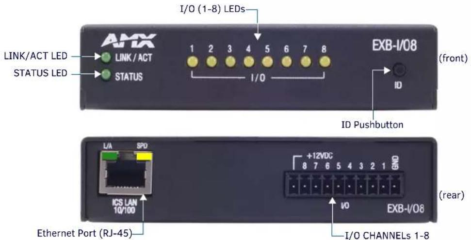
FIG. 7 EXB-I/08
NOTE: The I/Os on this Module are not dry closure; they are electronic switches that float at 3V when Off. Therefore, they should not be expected to work in situations that require true dry contact (or dry closure). The I/Os do work with AMX PC1, PC2, UPC20 and UPC20+.
EXB-I/08 Product Specifications
In addition to the features described in the ICSLan Device Control Boxes - Common Features table on page 9, the components and specifications listed below are specific to the EXB-I/08 module:
| EXB-I/O8 Specifications | |
| Power Requirements | |
| PoE (Power-over-Ethernet) | |
| Power Draw • Idle (min): 30mA 1.44 watts• Busy (max): 40mA 1.92 wattsNote: Maximum power draw does not include any external devices that may draw power from the 12V terminal. | |
| Front Panel Components | |
| I/O LEDs (1-8) 8 (yellow) LEDs | light to indicate activity on I/O channels 1-8.Note: Active = output high. |
| Rear Panel Components | |
| I/O Ports (1-8) Connector: 3.5mm Phoenix – 10-positionsThis connector is designated as Port 1, Channels 1-8 | |
| Included Accessories • 10-pin 3.5 mm mini-Phoenix (female) I/O connector (41-5107) | |
| Other AMX Equipment | • NXA-ENET8POE Gigabit Ethernet Switch (FG2178-62)• PS-POE-AF PoE Injector (FG423-80)• AVB-VSTYLE-SURFACE-MNT V-Style Module Surface Mount (FG1010-722)• AVB-VSTYLE-RMK-1U V-Style Module Tray (FG1010-720)• AVB-VSTYLE-RMK-FILL-1U V-Style Module Tray w/ fill plates (FG1010-721)• AVB-VSTYLE-POLE-MNT V Style Module Pole Mount (FG1010-723) |
Connections and Wiring
LAN/PoE Port (RJ45)
The LAN/PoE (RJ45) port on the rear panel provides 10/100 BaseT network connectivity. This port is common to all EXB Modules. Use standard Cat5/6/6E ethernet cable to connect the EXB Module to the LAN.
Refer to the LAN/PoE Port section on page 13 for the pinout configuration for this port.
Port 1 (I/O 1-8)
The I/O Connector on the rear panel is an 10-pin 3.5mm captive-wire connector that provides eight I/O contacts (1-8) as well as PWR and GND.
| I/08 Connector Pin Assignments | |
| Signal Function | |
| +12V + 12VDC (max current 200 mA) | |
| 8 Channel 8 – Voltage/current same as Channel 1 | |
| 7 Channel 7 – Voltage/current same as Channel 1 | |
| 6 Channel 6 – Voltage/current same as Channel 1 | |
| 5 Channel 5 – Voltage/current same as Channel 1 | |
| 4 Channel 4 – Voltage/current same as Channel 1 | |
| 3 Channel 3 – Voltage/current same as Channel 1 | |
| 2 Channel 2 – Voltage/current same as Channel 1 | |
| 1 Channel 1 | |
| GND Ground |
- When used for voltage inputs, the I/O port detects a low signal (0 - 1.5 VDC) as a Push, and a high signal (3.3 - 5 VDC) as a Release.
- Although a high signal is defined as 3.3 - 5 VDC, this port can handle up to 12V without harm.
- Power supplied from this terminal is in addition to the maximum power requirement for the unit.
- When used for outputs, the I/O port acts as a switch to GND and is rated for 200mA @ 12 VDC.
NOTE: The I/Os on this Module are not dry closure; they are electronic switches that float at 3V when Off. Therefore, they should not be expected to work in situations that require true dry contact (or dry closure). The I/Os do work with AMX PC1, PC2, UPC20 and UPC20+.
NetLinx Programming
EXB-108 Port Assignments
| EXB-I08 Port Assignments | |
| Port Description | |
| 1 All I/Os (channels 1-8) |
EXB-108 Channel Assignments
| EXB-I08 Channel Assignments | |
| Channel Description | |
| 1-8 Channels 1-8 represent I/Os 1-8. |
EXB-I/08 SEND\_COMMANDs
The following NetLinx SEND_COMMANDs are supported by the EXB-I/08 Module:
| EXB-I/O8 SEND_COMMANDs | |||
| Command Page Reference Command Page Reference | |||
| GET DBT | page 38 | SET DBT | page 41 |
| GET INPUT | page 38 | SET DBTF | page 42 |
| GET OFF DELAY | page 38 | SET INPUT | page 42 |
| GET ON DELAY | page 38 | SET_NDX_DESC | page 42 |
| LED-DIS | page 39 | SET OFF DELAY | page 43 |
| LED-EN | page 39 | SET ON DELAY | page 43 |
| REBOOT | page 40 | ||
Telnet commands
Refer to the Appendix A: Terminal (Telnet) Commands section on page 46 for a listing of all supported Telnet commands.
EXB-IRS4
Overview
The EXB-IRS4 (FG2100-23) Networked IR & I/O Device provides four IR/Serial and four I/O ports.
The EXB-IRS4 supports all standard uses of these ports, including utilizing the I/O ports as monitor ports for the IR ports. Each port in the EXB-IRS4 stores programmed commands for IR- or serial-controlled devices.
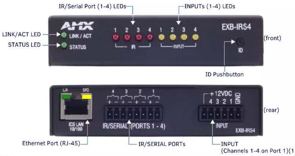
FIG. 8 EXB-IRS4
EXB-IRS4 Product Specifications
In addition to the features described in the ICSLan Device Control Boxes - Common Features table on page 9, the components and specifications listed below are specific to the EXB-IRS4 module:
| EXB-IRS4 Specifications | |
| Power Requirements | |
| PoE (Power-over-Ethernet) | |
| Power Draw • Idle (min): 40mA 1.92 watts | • Busy (max): 50mA 2.4 watts |
| Front Panel Components | |
| IR/Serial 1-4 TX LEDs 4 (red) LEDs indicate outgoing (TX) activity on Ports 1-4. | |
| Input RX LEDs 4 (yellow) LEDs indicate incoming (RX) activity on PortS 1-4. | |
| Rear Panel Components | |
| IR/Serial Ports Connector: 3.5mm Phoenix - 8 position. This connector contains Ports 1-4. | |
| Input Port | Connector: 3.5mm Phoenix - 6 position. This is the connector for I/O inputs 1-4. See the NetLinx Programming section on page 29 for more information about port and channel assignments. |
| Included Accessories • 6-pin 3.5 mm mini-Phoenix female Input connector (41-5063)• Two CC-NIRC IR Emitters | |
| Other AMX Equipment | • NXA-ENET8POE Gigabit Ethernet Switch (FG2178-62)• PS-POE-AF PoE Injector (FG423-80)• AVB-VSTYLE-SURFACE-MNT V-Style Module Surface Mount (FG1010-722)• AVB-VSTYLE-RMK-1U V-Style Module Tray (FG1010-720)• AVB-VSTYLE-RMK-FILL-1U V-Style Module Tray w/ fill plates (FG1010-721)• AVB-VSTYLE-POLE-MNT V Style Module Pole Mount (FG1010-723) |
Connections and Wiring
LAN/PoE Port (RJ45)
The LAN/PoE (RJ45) port on the rear panel provides 10/100 BaseT network connectivity. This port is common to all EXB Modules. Use standard Cat5/6/6E ethernet cable to connect the EXB Module to the LAN.
Refer to the LAN/PoE Port section on page 13 for the pinout configuration for this port.
IR/Serial Port Bank (Ports 1-4)
The IR/Serial Port Bank on the rear panel is an 8-pin 3.5mm captive-wire connector that supports up to four (optional) CC-NIRC IR Emitters.
| IR/Serial Connector Pin Assignments | |||
| Signal Function | Signal Function | ||
| 4 + | IR/Serial port 4 + | 2 + | IR/Serial port 2 + |
| 4 - | IR/Serial port 4 - | 2 - | IR/Serial port 2 - |
| 3 + | IR/Serial port 3 + | 1 + | IR/Serial port 1 + |
| 3 - | IR/Serial port 3 - | 1 - | IR/Serial port 1 - |
Input Port Bank
The Input Port Bank on the rear panel is an 6-pin 3.5mm captive-wire connector that supports up to four (optional) CC-NIRC IR Emitters.
The Input channel detects a low signal (0 - 1.5 VDC) as a Push, and a high signal (3.3 - 5 VDC) as a Release.
| I/O Connector Pin Assignments | |
| Signal Function | |
| +12VDC | +12VDC (max current 200 mA) |
| 4 | Port 4, Channel 255 |
| 3 | Port 3, Channel 255 |
| 2 | Port 2, Channel 255 |
| 1 | Port 1, Channel 255 |
| GND | Ground |
NOTE: Although a high signal is defined as 3.3 - 5 VDC, this port can handle up to 12V without harm.
NOTE: The maximum baud rate for ports using DATA mode is 9600. Also, DATA mode works best when using a short cable length (<10 feet).
Input Linking
The EXB-IRS4 has 4 IR-Tx ports (labelled "IR/SERIAL") and 4 associated input pins. Each of the 4 input pins is directly associated with one IR-Tx port. Port #1 is associated with input pin #1 and so on.
Any of the 4 IR-Tx ports/pins on an EXB-IRS4 can be run in either "unlinked" or "linked" mode:
Unlinked Mode (Default)
Unlinked mode is the default mode at boot up. When an IR/SERIAL port is unlinked the input pin state has no effect on the IR-Tx port.
Linked Mode
Linked mode is intended to provide the function of a “light switch” for the power state of a television via the EXB-IRS4’s IR interface.
When a port is linked, the power state (on/off) of the TV is sensed via the input pin and factored into the logic of whether or not to send power on/off IR pulses out the port to the TV. In this way, even a TV with a simple power toggle IR code can be reliably turned on and off by the EXB-IRS4.
When in linked mode, the IR/SERIAL port is in one of 3 mutually exclusive states: POD, PON or POF (see the IO-Linked Modes table on page 28).
Input Pin
The firmware on the EXB-IRS4 senses the high/low state of the pin and always reports that state to the master via PUSH/RELEASE messages on ports 1-4 channel 255. This behavior persists regardless of whether the pin is linked or unlinked.
Entering/Exiting Linked Mode
Linked mode is entered by sending the "SET INPUT LINK" command (see page 42) to a specific [D:P:S].
The EXB-IRS4 firmware will accept a port number from 1 to 4 and will enable linked mode on that port.
Linked Modes
The following table describes the four linking modes on the EXB-IRS4:
| IO-Linked Modes | |
| Unlinked(default) | Exited by SET INPUT LINK(see SET INPUT LINK on page 42)LEDs reflect the power state of the 4 input pinsChannel 255 reports the power state of the 4 input pins on their default port#All POD (page 39), PON (page 40), POF (page 39) messages are ignoredNo IR activity due to pin state |
| POD(default linked state) | In POD state, the PON/POF behavior is disabled and the state of the input pin is not used to trigger the sending of power on/off pulses. This is the default state of a linked port upon receiving the “SET INPUT LINK” command.Exited by PON (page 40), POF (page 39), or SET INPUT LINK 0 (page 42)LEDs reflect the power state of the 4 input pinsChannel 255 reports the power state of the 4 input pins on their linked port#(s)PON, POF messages are appliedNo IR activity due to pin state |
| PON In the PON state, the IR/SERIAL port is used to keep the TV powered on.When in PON state, if the TV is sensed via the input pin to be off, power-on pulses are sent out the IR/SERIAL port until the TV is sensed to be on.Exited by POD (page 39), POF (page 39), or SET INPUT LINK 0 (page 42)LEDs reflect the power state of the 4 input pinsChannel 255 reports the power state of the 4 input pins on their linked port#(s)POD, POF messages are appliedIR activity to maintain power ON pin stateNOTE:When an IR/SERIAL port is linked and in PON state, the time delay set by the PTON Send Command (see page 40) is used for power pulses sent out the port. | |
| POF In the POF state, the IR/SERIAL port is used to keep the TV powered off.When in POF state, if the TV is sensed via the input pin to be on, power-off pulses are sent out the IR/SERIAL port until the TV is sensed to be off.Exited by PON (page 40), POD (page 39), or SET INPUT LINK 0 (page 42)LEDs reflect the power state of the 4 input pinsChannel 255 reports the power state of the 4 input pins on their linked port#(s)POD, PON messages are appliedIR activity to maintain power OFF pin stateNOTE:When an IR/SERIAL port is linked and in POF state, the time delay set by the PTOF Send Command (see page 40) is used for power pulses sent out the port. | |
NetLinx Programming
EXB-IRS4 Port Assignments
| EXB-IRS4 Port Assignments | |
| Port Description | |
| 1 IR/Serial | Port 1 and Input 1 |
| 2 IR/Serial | Port 2 and Input 2 |
| 3 IR/Serial | Port 3 and Input 3 |
| 4 IR/Serial | Port 4 and Input 4 |
EXB-IRS4 Channel Assignments
| EXB-IRS4 Channel Assignments | |
| Channel Description | |
| 1 - 229 IR commands. | If the EXB-IRS4 receives a channel code below 230 and it doesn't exist in the IR data, then it will send a channel off command back to the master as a NAK mechanism. |
| 230 - 253 | If the EXB-IRS4 receives a channel code >= 230 and <=253 and it doesn't exist in the IR data, then it will fail silently (NetLinx uses the feedback channels for other purposes. |
| 254 Used for feedback w/ 'PON' and 'POF' commands. | If the EXB-IRS4 receives from the master a channel code of 254, and it doesn't exist in the IR data, then it fails silently. |
| 255 Power status. (Shadows I/O Link channel status). | If the EXB-IRS4 receives from the master a channel code of 255 and it doesn't exist in the IR data, then it will fail silently. |
NOTE: The EXB-IRS4 can process up to two IR or serial device channel setting commands simultaneously.
EXB-IRS4 SEND\_COMMANDs
The following NetLinx SEND_COMMANDs are supported by the EXB-IRS4Module:
| EXB-IRS4 SEND_COMMANDs | |||
| Command Page Reference Command Page Reference | |||
| CAROFF | page 35 | PON | page 40 |
| CARON | page 35 | PTOF | page 40 |
| CH | page 36 | PTON | page 40 |
| CP | page 36 | REBOOT | page 40 |
| CTOF | page 37 | SET_NDX_DESC | page 42 |
| CTON | page 37 | SET BAUD | page 41 |
| GET BAUD | page 38 | SET DBT | page 41 |
| GET MODE | page 38 | SET INPUT LINK | page 42 |
| IROFF | page 39 | SET IO LINK | page 42 |
| LED-DIS | page 39 | SET MODE | page 42 |
| LED-EN | page 39 | SP | page 43 |
| POD | page 39 | XCH | page 44 |
| POF | page 39 | XCHM | page 44 |
Telnet commands
Refer to the Appendix A: Terminal (Telnet) Commands section on page 46 for a listing of all supported Telnet commands.
EXB-MP1
Overview
The EXB-MP1 Networked Television Control System Device (FG2100-26) provides one Serial (RS-232) port, one I/O port, one IR (TX) and one IR (RX) port (FIG. 9).
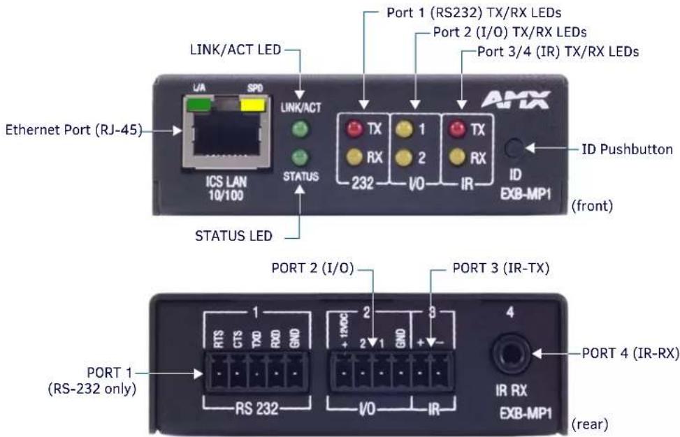
FIG. 9 EXB-MP1
EXB-MP1 Product Specifications
In addition to the features described in the ICSLan Device Control Boxes - Common Features table on page 9, the components and specifications listed below are specific to the EXB-MP1 module:
| EXB-MP1 Specifications | |
| Power Requirements | |
| PoE (Power-over-Ethernet) | |
| Power Draw • Idle (min): 40mA | 1.92 wattsBusy (max): 40mA 1.92 watts |
| Front Panel Components | |
| Ethernet / PoE Connector RJ- | 45 connector provides TCP/IP communication and PoE.This is an Auto MDI/MDI-X enabled port, therefore either straight-through or crossover Ethernet cables can be used. |
| 232 TX/RX LEDs | 2 LEDs light to Indicate Incoming (RX- yellow) and outgoing (TX - red) activity on the Serial port (Port 1). |
| I/O (1 & 2) LEDs | 2 (yellow) LEDs light to indicate which channels (1-2) are active (output high) on the I/O port (Port 2). |
| IR TX/RX LEDs 2 LEDs light to | indicate incoming (RX - yellow) and outgoing (TX - red) activity on the IR Port.· Port 3 = IR Transmit (TX)· Port 4 = IR Receive (RX) |
| RS232 Port (Port 1) Connector: 3.5mm Phoenix - 5 position (Serial RS232 only) | |
| I/O Port (Port 2) Connector: 3.5mm Phoenix - 4 position | |
| IR-TX/Serial Port (Port 3) Connector: 3.5mm Phoenix - 2 position | |
| IR-RX Port (Port 4) | Connector: 1/8th inch (6.35 mm) TRS connector |
| Included Accessories | · CC-NIRC IR Emitter· 5-pin 3.5 mm mini-Phoenix (female) RS-232 connector (41-0336)· 4-pin 3.5 mm mini-Phoenix (female) I/O connector (41-5047) |
| Other AMX Equipment | • IR03 External IR Receiver Module (FG-IR03)• NXA-ENET8POE Gigabit Ethernet Switch (FG2178-62)• PS-POE-AF PoE Injector (FG423-80)• AVB-VSTYLE-SURFACE-MNT V-Style Module Surface Mount (FG1010-722)• AVB-VSTYLE-RMK-1U V-Style Module Tray (FG1010-720)• AVB-VSTYLE-RMK-FILL-1U V-Style Module Tray w/ fill plates (FG1010-721)• AVB-VSTYLE-POLE-MNT V Style Module Pole Mount (FG1010-723) |
NOTE: Refer to the Common Features section on page 2 for product specifications common to all EXB Modules.
Connections and Wiring
LAN/PoE Port (RJ45)
The LAN/PoE (RJ45) port on the front panel provides 10/100 BaseT network connectivity. Use standard Cat5/6/6E ethernet cable to connect the EXB Module to the LAN. Refer to the LAN/PoE Port section on page 13 for the pinout configuration for this port.
Port 1 (RS-232 only)
Port 1 on the rear panel is a 5-pin 3.5mm captive-wire connector that supports RS-232 (only) serial communication.
| EXB-MP1 Port 1 Pin Assignments | |
| Signal Function | |
| RTS Request to send | |
| CTS Clear to send | |
| TXD Transmit data | |
| RXD Receive data | |
| GND Signal ground |
Port 2 (I/O)
Port 2 on the rear panel is an 4-pin 3.5mm captive-wire connector that provides two I/O contacts (1-2) as well as PWR and GND.
| EXB-MP1 Port 2 Pin Assignments | |
| Signal Function | |
| +12VDC | -12VDC (max current 200 mA) |
| 2 Channel 2 - Same as Channel 1. | |
| 1 Channel 1 | |
| GND Ground | |
- When used for voltage inputs, the I/O port detects a low signal (0 - 1.5 VDC) as a Push, and a high signal (3.3 - 5 VDC) as a Release.
- Although a high signal is defined as 3.3 - 5 VDC, this port can handle up to 12V without harm.
- When used for outputs, the I/O port acts as a switch to GND and is rated for 200mA @ 12 VDC.
NOTE: The I/Os on this Module are not dry closure; they are electronic switches that float at 3V when Off. Therefore, they should not be expected to work in situations that require true dry contact (or dry closure). The I/Os do work with AMX PC1, PC2, UPC20 and UPC20+.
Port 3 (IR-TX/Serial)
Port 3 on the rear panel is an 2-pin 3.5mm captive-wire IR-TX connector that supports one (optional) CC-NIRC IR Emitter.
| EXB-MP1 Port 3 Pin Assignments | |
| Signal Function | |
| + IR/Serial port 1 + | |
| - IR/Serial port 1 - |
Port 4 (IR-RX)
Port 4 on the rear panel is a 1/8th inch (6.35 mm) IR-RX (TRS) connector.
NOTE: The maximum baud rate for ports using DATA mode is 19,200. Also, DATA mode works best when using a short cable length (< 10 feet).
NetLinx Programming
EXB-MP1 SEND\_COMMANDs
The following NetLinx SEND_COMMANDs are supported by the EXB-MP1 Module:
| EXB-MP1 SEND_COMMANDs | |||
| Command Page Reference Command Page Reference | |||
| B9MOFF | page 35 | IROFF | page 39 |
| B9MON | page 35 | LED-DIS | page 39 |
| CAROFF | page 35 | LED-EN | page 39 |
| CARON | page 35 | REBOOT | page 40 |
| CH | page 36 | RXCLR | page 41 |
| CHARD | page 36 | RXOFF | page 41 |
| CHARDM | page 36 | RXON | page 41 |
| CP | page 36 | SET_NDX_DESC | page 42 |
| CTOF | page 37 | SET BAUD | page 41 |
| CTON | page 37 | SET DBT | page 41 |
| CTSPSH | page 37 | SET DBTF | page 42 |
| CTSPSH OFF | page 37 | SET INPUT | page 42 |
| ESCSEQOFF | page 37 | SET MODE | page 42 |
| ESCSEQON | page 37 | SET OFF DELAY | page 43 |
| GET BAUD | page 38 | SET ON DELAY | page 43 |
| GET DBT | page 38 | SP | page 43 |
| GET INPUT | page 38 | TSET BAUD | page 43 |
| GET MODE | page 38 | TXCLR | page 43 |
| GET OFF DELAY | page 38 | XCH | page 44 |
| GET ON DELAY | page 38 | XCHM | page 44 |
| HSOFF | page 38 | XOFF | page 44 |
| HSON | page 39 | XON | page 44 |
SEND\_STRING Escape Sequences
The EXB-COM2 and EXB-MP1 support several special SEND_STRING escape sequences. If any of the escape sequences are found anywhere within a SEND_STRING program instruction, they will be treated as a command and not the literal characters.
See the SEND_STRING Escape Sequences section on page 45 for details.
Telnet commands
Refer to the Appendix A: Terminal (Telnet) Commands section on page 46 for a listing of all supported Telnet commands.
EXB-REL8
Overview
The EXB-REL8 Networked 8-Relay Device (FG2100-20) provides eight relays that support devices that employ simple momentary or latching contact-closure control, with LED feedback.
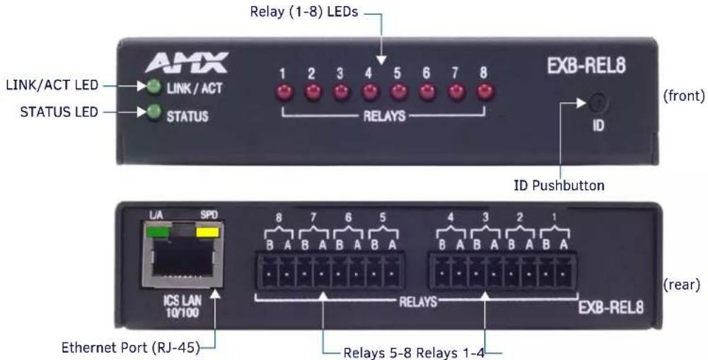
FIG. 10 EXB-REL8
EXB-REL8 Product Specifications
In addition to the features described in the ICSLan Device Control Boxes - Common Features table on page 9, the EXB-REL8 module features the following components:
| EXB-REL8 Specifications | |
| Power Requirements | |
| PoE (Power-over-Ethernet) | |
| Power Draw: • Idle (min): 40mA 1.92 watts• Busy (max): 70mA 3.36 watts | |
| Front Panel Components | |
| Relay LEDs (1-8) 8 (red) LEDs light to indicate which relays 1-8 are active (active = contacts closed). | |
| Rear Panel Components | |
| 1 Relay Port Connector: 3.5mm Phoenix – 16 positions.This port is designated as Port 1, Channels 1-8 | |
| Included Accessories • Two 8-pin 3.5 mm mini-Phoenix female Relay connectors (41-5083)• 8-position Commoning Strlp for 3.5mm mlni-Phoenix (41-2105-01) | |
| Other AMX Equipment | • NXA-ENET8POE Gigabit Ethernet Switch (FG2178-62)• PS-POE-AF PoE Injector (FG423-80)• AVB-VSTYLE-SURFACE-MNT V-Style Module Surface Mount (FG1010-722)• AVB-VSTYLE-RMK-1U V-Style Module Tray (FG1010-720)• AVB-VSTYLE-RMK-FILL-1U V-Style Module Tray w/ fill plates (FG1010-721)• AVB-VSTYLE-POLE-MNT V Style Module Pole Mount (FG1010-723) |
Connections and Wiring
LAN/PoE Port (RJ45)
The LAN/PoE (RJ45) port on the rear panel provides 10/100 BaseT network connectivity. This port is common to all EXB Modules. Use standard Cat5/6/6E ethernet cable to connect the EXB Module to the LAN. Refer to the LAN/PoE Port section on page 13 for the pinout configuration for this port.
Port 1 (Relay Connector)
The Relay Connectors on the rear panel are two 8-pin 3.5mm captive-wire connectors that provide A and B connections for eight SPST Relay channels (1-8).
- Connectors labeled A for Common, B for Output.
• These relays are independently controlled, isolated and normally open. - The relay contacts are rated for a maximum of 1 A @ 0-24 VAC or 0-28 VDC (resistive).
| Relay Connector Pinouts | ||
| First Relay Connector Pinout Second Relay Connector Pinout | ||
| Pin Description Pin Description | ||
| 1 Channel 1A 1 Channel 5A | ||
| 2 Channel 1B 2 Channel 5B | ||
| 3 Channel 2A 3 Channel 6A | ||
| 4 Channel 2B 4 Channel 6B | ||
| 5 Channel 3A 5 Channel 7A | ||
| 6 Channel 3B 6 Channel 7B | ||
| 7 Channel 4A 7 Channel 8A | ||
| 8 Channel 4B 8 Channel 8B | ||
NOTE: An 8-position metal Commoning Strip (41-2105-01) is provided with each EXB-REL8 to common multiple relays.
NetLinx Programming
EXB-REL8 Port Assignments
| EXB-REL8 Port Assignments | |
| Port Description | |
| 1 | All Relays (channels 1-8) |
EXB-REL8 Channel Assignments
| EXB-REL8 Channel Assignments | |
| Channel | Description |
| 1-8 | Channels 1-8 represent Relays 1-8. |
EXB-REL8 SEND\_COMMANDs
The following NetLinx SEND_COMMANDs are supported by the EXB-REL8 Module:
| EXB-REL8 SEND_COMMANDs | |||
| Command | Page Reference | Command | Page Reference |
| LED-DIS | page 39 | REBOOT | page 40 |
| LED-EN | page 39 | SET_NDX_DESC | page 42 |
Telnet commands
Refer to the Appendix A: Terminal (Telnet) Commands section on page 46 for a listing of all supported Telnet commands.
NetLinx Send Commands
The following NetLinx SEND_COMMANDs are supported by the EXB-xxx modules.
NOTE: Refer to the Appendix A: Terminal (Telnet) Commands section on page 46 for a listing of all supported Telnet commands.
| NetLinx Send Commands | ||
| Command Description | EXB Modules | |
| B9MOFF | Set the port's communication parameters for stop and data bits according to the software settings on the RS-232 port (default).Disables 9-bit in 232/422/455 mode.By default, this returns the Communication settings on the serial port to the last programmed parameters.This command works in conjunction with the 'B9MON' command elevated. | • E X B - C• E X B - M O M 2P 1 |
| Syntax:B9MOFFExample:SEND_COMMAND SOMEDEVICE_1,"B9MOFF"Sets the port settings on SOMEDEVICE to match the port's configuration settings. | ||
| B9MON | Override and set the current communication settings and parameters on the RS-232 serial port to 9 data bits with one stop bit.Enables 9-bit in 232/422/485 mode.This command works in conjunction with the 'B9MOFF' command Syntax:B9MONExample:SEND_COMMAND SOMEDEVICE_1,"B9MON"Resets the SOMEDEVICE port's communication parameters to nine data bits and one stop bit. | • E X B - C• E X B - M O M 2P 1 |
| CAROFF Disable the IR carrier signal until a 'CARON' command is received. | Syntax:CAROFFExample:SEND_COMMAND IR_1,"CAROFF"Stops transmitting IR carrier signals to the IR_1 port. | • E X B - I R S 4• E X B - M P 1 |
| CARON Enable the IR carrier signals (default). | Syntax:CARONExample:SEND_COMMAND IR_1,"CARON"Starts transmitting IR carrier signals to the IR_1 port. | • E X B - I R S 4• E X B - M P 1 |
| NetLinx Send Commands (Cont.) | ||
| Command Description | EXB Modules | |
| CH Send IR pulses for the selected a channel.All channels below 100 are transmitted as two digits. If the IR code for ENTER (function #21) is loaded, an Enter will follow the number.If the channel is greater than or equal to (>=) 100, then IR function 127 or 20 (whichever exists) Is generated for the one hundred digit.This command uses a binary parameter. To generate a Send Command of this type, use string expressions, such as: ''CH', 01".NOTE:Set the Pulse and Wait times with 'CTON' (page 37) and 'CTOF' (page 37).Syntax:'CH',Variable:channel number = 0 - 199.Example:SEND_COMMAND IR_1, ''CH',18"The EXB-IRS4 performs the following:Transmits IR signals for 1 (IR code 11). The transmit time is set with the CTON command.Waits until the time set with the CTOF command elapses.Transmits IR signals for 8 (IR code 18).Waits for the time set with the CTOF command elapses. If the IR code for Enter (IR code 21) is programmed, the IRS4 performs the following steps.Transmits IR signals for Enter (IR code 21).Waits for the time set with the CTOF command elapses. | ||
| CHARD | Set the delay time between all transmitted characters to the value specified (in 100 microsecond increments).Syntax:CHARD-Variable:time: 0 - 10000 (1 second)Example:SEND_COMMAND RS232_1, ''CHARD-10'Sets a 1-millisecond delay between all transmitted characters. | E X B - CO M 2E X B - MP 1 |
| CHARDM | Set the delay time between all transmitted characters to the value specified (in 1 millisecond increments).Syntax:CHARDM-Variable:time: 0 - 1000 (1 second)Example:SEND_COMMAND RS232_1, ''CHARDM-10'Sets a 10-millisecond delay between all transmitted characters. | E X B - CO M 2E X B - MP 1 |
| CP | Halt and clear all active or buffered IR commands, and then send a single IR pulse.This command uses a binary parameter. To generate a Send Command of this type, use string expressions, such as: ''CH', 01".NOTE:Set the Pulse and Wait times with 'CTON' and 'CTOF'.Syntax:'CP',Variable:code = IR port's channel value 0 - 252 (253 - 255 reserved).Example:SEND_COMMAND IR_1, ''CP',02"Clears the active/buffered commands and pulses IR_1 port's channel 2. | E X B - IR S 4E X B - MP 1 |
| NetLinx Send Commands (Cont.) | |||
| Command Description | EXB Modules | ||
| CTOF | Set the duration of the Off time (no signal) between IR pulses for channel and IR function transmissions.Sets the delay time between pulses generated by the 'CH' or 'XCH' Send Commands in tenths of seconds.Off time settings are stored in non-volatile memory.This command uses a binary parameter. To generate a Send Command of this type, use string expressions, such as: ''CH', 01'.Syntax:'CTOF',Variable:time = 0 - 255. Given in 1/10ths of a second. Default is 5 (0.5 seconds).Example:SEND_COMMAND IR_1, ''CTOF',10'Sets the Off time between each IR pulse to 1 second. | • E X B - IE X B - M | R S 4P 1 |
| CTON Set the total time | of IR pulses transmitted and Is stored in non-volatile memory.This command sets the pulse length for each pulse generated by the 'CH' (page 36) or 'XCH' (page 44) Send Commands in tenths of seconds.This command uses a binary parameter. To generate a Send Command of this type, use string expressions, such as: ''CH',01'.Syntax:'CTON',Variable:time = 0 - 255. Given in 1/10ths of a second. Default is 5 (0.5 seconds).Example:SEND_COMMAND IR_1, ''CTON',20'Sets the IR pulse duration to 2 seconds. | • E X B - IE X B - M | R S 4P 1 |
| CTSPSH | Enable Pushes, Releases, and status information to be reported via channel 255 using the CTS hardware handshake input.Note: If Clear To Send (CTS) is high, the channel is ON Syntax:CTSPSHExample:SEND_COMMAND RS232_1, ''CTSPSH'Sets the RS232_1 port to detect changes on the CTS input.NOTE: Channel 255 (on each port) reflects the state of the CTS input if a 'CTSPSH' command was sent to the port. | • E X B - CE X B - M | O M 2P 1 |
| CTSPSH OFF | Disable Pushes, Releases, and Status information to be reported via channel 255.Turns CTSPSH Off.Note: If Clear To Send (CTS) is high, the channel is ON.Syntax:CTSPSH OFFExample:SEND_COMMAND RS232_1, ''CTSPSH OFF'Turns off CTSPSH for the specified device.Disables the RS232_1 port to detect changes on the CTS input.NOTE: Channel 255 (on each port) reflects the state of the CTS input if a 'CTSPSH' command was sent to the port. | • E X B -CE X B - M | O M 2P 1 |
| ESCSEQOFF | Disables SEND_STRING escape sequences (see the SEND_STRING Escape Sequences section on page 45). | • E X B -CE X B - M | O M 2P 1 |
| ESCSEQONCommand Description | Enables SEND_STRING escape sequences (see the SEND_STRING Escape Sequences section on page 45).EXB Modules | • E X B -CE X B - M | O M 2P 1 |
| GET BAUD Get the RS-232/422/485 port's current communication parameters.The port sends the parameters to the device that requested the information.Syntax:GET BAUDExample:SEND_COMMAND RS232_1," 'GET BAUD'"The port responds with:485 | • E X B - C • E X B - I • E X B - M | O M 2 R S 4 P 1 | |
| GET DBT Returns current debounce value.Syntax:SEND_COMMAND," 'GET DBT'"Example:SEND_COMMAND DEVICE_1," 'GET DBT'"Returns current debounce value for DEVICE_1. | • E X B - I • E X B - M | / O 8 P 1 | |
| GET INPUT Get the active state for the selected channels.An active state can be high (logic high) or low (logic low or contact closure). Channel changes,Pushes, and Releases generate reports based on their active state.The port responds with either 'HIGH' or 'LOW'.Syntax:GET INPUTVariable:channel = Input channel 1 - 8.Example:SEND_COMMAND IO," 'GET INPUT 1'"Gets the I/O port's active state.The system could respond with:INPUT1 ACTIVE HIGH | • E X B - I • E X B - I • E X B - M | / O 8 R S 4 P 1 | |
| GET MODE | Poll the IR/Serial port's configuration parameters and report the active mode settings to the device requesting the information.Syntax:GET MODEThe port responds with:,<io link channel>.Example:SEND_COMMAND IR_1," 'GET MODE"The system could respond with:PORT 4 IR,CARRIER,IO LINK 0 | • E X B - I • E X B - M | R S 4 P 1 |
| GET OFF DELAY | Returns the off delay for the specified port and channel in a STRING message. See SET OFF DELAY.Syntax:GET OFF DELAY | • E X B - I • E X B - M | / O 8 P 1 |
| GET ON DELAY | Returns the on delay for the specified port and channel in a STRING message. See SET ON DELAY.Syntax:GET ON DELAY | • E X B - I • E X B - M | / O 8 P 1 |
| HSOFF Disable hardware handshaking (default).NOTE:RTS is asserted by default. Controlled by escape sequences described in the SEND_STRING Escape Sequences section on page 45.Syntax:HSOFFExample:SEND_COMMAND RS232_1," 'HSOFF'"Disables hardware handshaking on the RS232_1 device. | • E X B - C • E X B - M | O M 2 P 1 | |
| NetLinx Send Commands (Cont.) | ||
| Command Description | EXB Modules | |
| HSON Enable RTS (ready-to-send) and CTS (clear-to-send) hardware handshaking. NOTE: Note:RTS / CTS handshaking signals operate even if 485 is enabled. Syntax: HSON Example: SEND_COMMAND RS232_1,"'HSON" Enables hardware handshaking on the RS232_1 device. | • E X B - C • E X B - M | |
| IROFF | Halt and Clear all active or buffered IR commands being output on the designated port. Syntax: IROFF Example: SEND_COMMAND IR_1,"'IROFF" Immediately halts and clears all IR output signals on the IR_1 port. | • E X B - I • E X B - M |
| LED-DIS Disable LEDs. | Syntax: LED-DIS Example: SEND_COMMAND DEVICE_1,"'LED-DIS" Disables LEDs on DEVICE_1. NOTE: This parameter does not get stored in non-volatile memory. LEDs are enabled by default at each power-up. | All EXB Modules |
| LED-EN Enable LEDs (default). | Syntax: LED-EN Example: SEND_COMMAND DEVICE_1,"'LED-EN" Enables LEDs on DEVICE_1. | All EXB Modules |
| POD | Disable previously active 'PON' (power on) or 'POF' (power off) command settings. • Channel 255 changes are enabled. • This command is used in conjunction with the SET IO LINK command (page 42). Syntax: POD Example: SEND_COMMAND IR_1,"'POD" Disables the 'PON' and 'POF' command settings on the IR_1 device. | EXB-IRS4 |
| POF | Turn OFF a device connected to an IR port based on the status of the corresponding I/O Link input. • If at any time the IR sensor input reads that the device is ON (as in having been manually turned on at the front panel), IR function 28 (if available) or IR function 9 is automatically generated in an attempt to turn the device back OFF. • If three attempts fail, the IR port will continue executing commands in the buffer. • If there are no commands in the buffer, the IR port will continue executing commands in the buffer and trying to turn the device OFF until a 'PON' or 'POD' command is received. • If the IR port falls to turn the device OFF, a PUSH and RELEASE is made on channel 254 to indicate a power failure error. • You can only use the 'PON' and 'POF' commands when an IR device has a linked I/O channel. • Channel 255 changes are disabled after receipt of this command. Syntax: POF Example: SEND_COMMAND IR_1,"'POF" Sends power down IR commands 28 (if present) or 9 to the IR_1 device. NOTE: When an IR/SERIAL port is linked and in POF state, the time delay set by the PTOF Send Command (page 40) is used for power pulses sent out the port. See the Input Linking section on page 27 for details. | EXB-IRS4 |
| PON | Turn ON a device connected to an IR port based on the status of the corresponding I/O Link input.If at any time the IR sensor Input reads that the device is OFF (such as if one turned it off manually at the front panel), IR function 27 (if available) or IR function 9 is automatically generated in an attempt to turn the device back ON.If three attempts fail, the IR port will continue executing commands in the buffer and trying to turn the device On.If there are no commands in the buffer, the IR port will continue trying to turn the device ON until a 'POF' or 'POD' command is received.If the IR port fails to turn the device ON, a PUSH and RELEASE is made on channel 254 to indicate a power failure error.You can only use the 'PON' and 'POF' commands when an IR device has a linked I/O channel.Channel 255 changes are disabled after receipt of this command.Syntax:PONExample:SEND_COMMAND IR_1,""PON"'Sends power up IR commands 27 or 9 to the IR_1 port.NOTE:When an IR/SERIAL port is linked and in PON state, the time delay set by the PTON Send Command (page 40) is used for power pulses sent out the port. See the Input Linking section on page 27 for details. | EXB-IRS4 |
| PTOF Set the time duration between power pulses in .10-second increments.This time increment is stored in permanent memory.This command also sets the delay between pulses generated by the 'PON' or 'POF' Send Commands in tenths of seconds.It also sets the delay required after a power ON command before a new IR function can be generated. This gives the device time to power up and get ready for future IR commands.It also sets the delay required after a power ON command before a new IR function can be generated. This gives the device time to power up and get ready for future IR commands.This command uses a binary parameter. To generate a Send Command of this type, use string expressions, such as: " 'CH', 01".Syntax:'PTOF',Variable:time = 0 - 255. Given in 1/10ths of a second. Default = 15 (1.5 seconds).Example:SEND_COMMAND IR_1,""PTOF',15"Sets the time between power pulses to 1.5 seconds for the IR_1 device. | • E X B - I | |
| PTON Set the time duration between power pulses in .10-second increments.This time increment is stored in permanent memory.This command also sets the pulse length for each pulse generated by the 'PON' or 'POF' Send Commands in tenths of seconds.This command uses a binary parameter. To generate a Send Command of this type, use string expressions, such as: " 'CH', 01".Syntax:'PTON',Variable:time = 0 - 255. Given in 1/10ths of a second. Default = 15 (1.5 seconds).Example:SEND_COMMAND IR_1,""PTON',15"Sets the duration of the power pulse to 1.5 seconds for the IR_1 device. | • E X B - I | |
| REBOOT Reboot the Module. | Syntax:REBOOTExample:SEND_COMMAND DEVICE_1,""REBOOT"'Reboots DEVICE_1. | All EXBModules |
| RXCLR Clear all characters in the receive buffer waiting to be sent to the Master. | • E X B - C • E X B - M | O M 2 P 1 |
| Syntax: RXCLR Example: SEND_COMMAND RS232_1, ''RXCLR''Clears all characters in the receive buffer waiting to be sent to the Master. | ||
| RXOFF Disable the transmission of incoming received characters to the Master (default). | • E X B - C • E X B - M | O M 2 P 1 |
| Syntax: RXOFF Example: SEND_COMMAND RS232_1, ''RXOFF''Disable the transmission of incoming received characters to the Master (default). | ||
| RXON Start transmitting received characters to the Master. | • E X B - C • E X B - M | O M 2 P 1 |
| Enables sending incoming received characters to the Master. This command is automatically sent by the Master when a 'CREATE_BUFFER' program instruction is executed. Syntax: RXON Example: SEND_COMMAND RS232_1, ''RXON''Start the RS232_1 device's transfer of received characters to the Master. | ||
| SET BAUD Set the COM port's communication parameters. NOTE: This value is not saved in Non-Volatile memory, and is reset to default (9600,8,N,1) at power-up. Syntax: SET BAUD,[485] Variables: Baud: 115200, 57600, 38400, 19200, 9600, 4800, 2400, 1200, 600, 300, 150. Note: IR ports will only work up to 9600 baud for one way serial. Parity: N (none), O (odd), E (even), M (mark), S (space) Data: 7 or 8 data bits Stop: 1 or 2 stop bits 485 Disable (EXB-COM2 Port 1 only): Disables RS-485 mode and enables RS-232/422 485 Enable (EXB-COM2 Port 1 only): Enables RS-485 mode and disables RS-234/422 NOTE: The only valid 9 bit combination is (baud),N,9,1. Example: SEND_COMMAND DEVICE_1, ''SET BAUD 19200,N,8,1, 485 ENABLE'' Sets the DEVICE_1 port's communication parameters to 19,200 baud, no parity, 8 data bits, 1 stop bit, and enables RS-485 mode. NOTE: Note: The maximum baud rate for ports using DATA mode is 9600. Also, DATA mode works best when using a short cable length (< 10 feet). | • E X B - C • E X B - I • E X B - M | O M 2 R S 4 P 1 |
| SET DBT Set Debounce Mode in 10ms increments. • This setting applies to all channels of the specified port. • Range = 1 (10 ms) to 1000 (10 sec) • D e f a u l t = 3 0 Syntax: SET DBTExample: SEND_COMMAND DEVICE_1, 'SET DBT 20' Sets Debounce Mode to 200ms on DEVICE_1. NOTE: This value is not saved in Non-Volatile memory, and is reset to default (30) at power-up. | • E X B - I • E X B - I • E X B - M | / O 8 R S 4 P 1 |
| NetLinx Send Commands (Cont.) | |||
| Command Description | EXB Modules | ||
| SET DBTF | Set Debounce Mode in 2ms increments (set to last "DBT" or "DBTF" received).This setting applies to all channels of the specified port.Range = 1 (2 ms) to 1000 (2 sec)Syntax:SET DBTFExample:SEND_COMMAND DEVICE_1, 'SET DBTF 12'Sets Debounce Mode to 24ms on DEVICE_1. | ·E X B - IR·E X B - IR·E X B - MP 1 | |
| SET INPUT Sets the input channel's active state.An active state can be high (logic high) or low (logic low or contact closure). Channel changes,Pushes, and Releases generate reports based on their active state.Setting an input to ACTIVE HIGH will disable the output for that channel.Syntax:SET INPUTVariable:State = LOW or HIGHExample:SEND_COMMAND IO, 'SET INPUT 1 HIGH'Sets the I/O channel to detect a high state change, and disables output on the channel. | ·E X B - IR·E X B - MP 1 | ||
| SET INPUT LINK | Sets an IR device to link to an Input channel for use with 'PON' (page 40), 'POF' (page 40) and 'POD' (page 39) commands.The input channel is used for power sensing (via a PCS).Syntax:SET INPUT LINKSee the Input Linking section on page 27 for details.NOTE: “SET INPUT LINK” is aliased as “SET IO LINK”. | ·E X B - IR·E X B - IR·E X B - IR·E X B - IR·E X B - IR·E X B - IR·E X B - IR·E X B - IR·E X B - IR·E X B - IR·E X B - IR·E X B - IR·E X B - IR·E X B - IR·E X B - IR·E X B - IR·E X B - IR·E X A - IR·E X B - IR·E X B - IR·E X B - IR·E X B - IR·E X B - IR·E X B - IR·E X B - IR·E X B - IR·E X B - IR·E X B - IR·E X B - IR·E X B - IR·E X B - IR·E X B - IR·E X B - IR·E X B - IR·A - IR·E X B - IR·E X B - IR·E X B - IR·E X B - IR·E X B - IR·E X B - IR·E X B - IR·E X B - IR·E X B - IR·E X B - IR·E X B - IR·E X B - IR·E X B - IR·E X B - IR·E X B - IR·E X B - IR· | / 0 8R S 4P 1 |
| SET IO LINK | Link an IR or Serial port to a selected I/O channel for use with the 'POD' (page 39), 'PON' (page 40), and 'POF' (page 40) commands.The I/O status is automatically reported on channel 255 on the IR port. The I/O channel is used for power sensing (via a PCS or VSS).NOTE: This command is included for older programs only. The Input port is not an I/O. No output functions are available. 'SET IO LINK' applies the same configuration as the 'SET INPUT LINK' command.Syntax:SET IO LINKSee the Input Linking section on page 27 for details. | ·E X B - IR·E X B - IR·E X B - IR·E X B - IR·E X B - IR·E X B - IR·E X B - IR·E X B - IR·E X B - IR·E X B - IR·E X B - IR·E X B - IR·E X B - IR·E X B - IR·E X B - IR·E X B - IR·E E X B - IR·E X B - IR·E X B - IR·E X B - IR·E X B - IR·E X B - IR·E X B - IR·E X B - IR·E X B - IR·E X B - IR·E X B - IR·E X B - IR·E X B - IR·E X B - IR·E X B - IR·E X B - IR·E X B -IR·E X B - IR·E X B - IR·E X B - IR·E X B - IR·E X B - IR·E X B - IR·E X B - IR·E X B - IR·E X B - IR·E X B - IR·E X B - IR·E X B - IR·E X B - IR·E X B - IR·E X B - IR·E X B - IR·E X C - IR·E X B - IR·E X B - IR·E X B - IR·E X B - IR·E X B - IR·E X B - IR·E X B - IR·E X B - IR·E X B - IR·E X B - IR·E X B - IR·E X B - IR·E X B - IR·E X B - IR·E X B - IR·E X B - IR· | |
| SET MODE Sets an IR port to either IR, Serial or Data mode.Syntax:SET MODEVariable:mode =·IR (standard IR output with carrier),·SERIAL (IR without carrier and waveform inverted)·DATA (1-way serial/TTL)Example:SEND_COMMAND IR_1, ''SET MODE IR''Sets the IR_1 port to IR mode for IR control. | ·E X B - IR·E X B - IR·E X B - IR·E X B - IR·E X B - IR·E X B - IR·E X B - IR·E X B - IR·E X B - IR·E X B - IR·E X B - IR·E X B - IR·E X B - IR·E X B - IR·E X B - IR·E X B - IR· | R S 4P 1 | |
| SET_NDX_DESC Set Friendly name and location for NDP.Syntax:SET_NDX_DESC-friendly name:locationMax of 25 characters for friendly name and max of 25 characters for location. If more than 25 characters are sent for either friendly name or location, they will be truncated to a max of 25 characters.Neither the friendly name nor the location should contain a ":" character, as that is used as a delimiter.NOTE: This command requires a reboot to enable new settings. | All EXBModules | ||
| NetLinx Send Commands (Cont.) | ||
| Command Description | EXB Modules | |
| SET OFF DELAY | Sets the delay between the time the input senses a transition to the OFF state and when the corresponding channel is turned off.• The delay resets every time the channel senses the ON state.• Time can be from 1 millisecond to 60 minutes, units in milliseconds.• 0 = d i s a b l e d ( default).Syntax:SET OFF DELAY,,Example:SEND_COMMAND DEVICE_1,'SET OFF DELAY 1,100'Sets the OFF delay on Channel 1 to 1 second on DEVICE_1. | • E X B - I• E X B - M / O 8P 1 |
| SET ON DELAY | Sets the delay between the time the input senses a transition to the ON state and when the corresponding channel is turned on.• The delay resets every time the channel senses the OFF state.• Time can be from 1 millisecond to 60 minutes, units in milliseconds.• 0 = d i s a b l e d ( default).Syntax:SET ON DELAY,,Example:SEND_COMMAND DEVICE_1,'SET ON DELAY 1,100'Sets the ON delay on Channel 1 to 1 second on DEVICE_1. | • E X B - I• E X B - M / O 8P 1 |
| SP Generate a single IR | pulse.• Use 'CTON' (page 37) to set pulse lengths and 'CTOF' (page 37) for time off between pulses.• This command uses a binary parameter. To generate a Send Command of this type, use string expressions, such as: ''CH', 01”.Syntax:SP,Variable:code = IR code value 1 - 252 (253-255 reserved).Example:SEND_COMMAND IR_1, ''SP',25"Pulses IR code 25 on IR_1 device. | • E X B - I• E X B - M R S 4P 1 |
| TSET BAUD Set the COM | port's communication parameters for a device.TSET BAUD is Identical to SET BAUD.NOTE:This value is not saved in Non-Volatile memory, and is reset to default (9600,8,N,1) at power-up.Syntax:TSET BAUD,,,[485 ]Variables:• Baud: 115200, 76800, 57600, 38400, 19200, 9600, 4800, 2400, 1200, 600, 300, 150.• Parity: N (none), O (odd), E (even), M (mark), S (space)• D a t a : 7 o r 8 d a t a b l t s• Stop: 1 or 2 stop bits• 485 Disable (EXB-COM2 port 1 only): Disables RS-485 mode and enables RS-232/422• 485 Enable (EXB-COM2 port 1 only): Enables RS-485 mode and disables RS-234/422NOTE:The only valid 9 bit combination is (baud),N,9,1.Example:SEND_COMMAND RS232_1,"TSET BAUD 115200,N,8,1 485 ENABLE'"Sets the RS232_1 port's communication parameters to 115,200 baud, no parity, 8 data bits, 1 stop bit, and enables RS-485 mode.NOTE:Since this command does not save parameters to NV memory, the default data rate and format at power up is 9600, 8, N, 1. | • E X B - C O M 2• E X B - M P 1 |
| TXCLR | Stop and clear all characters waiting in the transmit out buffer and stops transmission.Syntax:TXCLRExample:SEND_COMMAND RS232_1,"TXCLR"Clears and stops all characters waiting in the RS232_1 device's transmit buffer. | • E X B - C O M 2• E X B - M P 1 |
| XCH | Transmit the selected channel IR codes in the format/pattern set by the 'XCHM' command. Syntax:XCHVariable:channel = 0 - 999.Example:For detailed usage examples, refer to the 'XCHM' command. | • E X B - I• E X B - M R S 4P 1 |
| XCHM Changes the IR output pattern for the 'XCH' Send Command. Syntax:XCHMVariable:extended channel mode = 0 - 4.Example:SEND_COMMAND IR_1, '''XCHM 3''Sets the IR_1 device's extended channel command to mode 3. Mode 0 Example (default): [x][x]Send_COMMAND IR_1, '''XCH 3''Trans mits t he IR co de as 3-enter. SEND_COMMAND IR_1, '''XCH 34''Trans mits t he IR co de as 3-4-enter. SEND_COMMAND IR_1, '''XCH 343''Trans mits t he IR co de as 3-4-3 -en ter. Mode 1 Example:SEND_COMMAND IR_1, '''XCH 3''Transmits the IR code as 0-0-3-enter. SEND_COMMAND IR_1, '''XCH 34''Transmits the IR code as 0-3-4-enter. SEND_COMMAND IR_1, '''XCH 343''Trans mits t he IR co de as 3-4-3 -en ter. Mode 2 Example:SEND_COMMAND IR_1, '''XCH 3''Transmits the IR code as 0-0-3. SEND_COMMAND IR_1, '''XCH 34''Transmits the IR code as 0-3-4. SEND_COMMAND IR_1, '''XCH 343''Trans mits t he IR co de as 3-4-3. Mode 3 Example: [[100][100]...]SEND_COMMAND IR_1, '''XCH 3''Trans mits t he IR co de as 0-3. SEND_COMMAND IR_1, '''XCH 34''Trans mits t he IR co de as 3-4. SEND_COMMAND IR_1, '''XCH 343''Transmits the IR code as 100-100-100-4-3. Mode 4: Mode 4 sends the same sequences as the 'CH' command. Only use Mode 4 with channels 0 - 199. | • E X B - I• E X B - M R S 4P 1 | |
| XOFF Disable software handshaking (default).Syntax:XOFFExample:SEND_COMMAND RS232_1, '''XOFF''Disables software handshaking on the RS232_1 device. | • E X B - C• E X B - M O M 2P 1 | |
| XON Enable software handshaking. Syntax:XONExample:SEND_COMMAND RS232_1, '''XON''Enables software handshaking on the RS232_1 device. | • E X B - C• E X B - M O M 2P 1 | |
SEND\_STRING Escape Sequences
The EXB-COM2 and EXB-MP1 support several special SEND_STRING escape sequences. If any of the character combinations listed below are found anywhere within a SEND_STRING program instruction, they will be treated as a command and not the literal characters.
Use the ESCSEQON and ESCSEQOFF NetLinx SEND_COMMANDS to control whether these are active or not. The ESCSEQON command must be precede the Escape Sequences, otherwise the strings will be processed normally.
| EXB-COM2 & EXB-MP1 SEND_STRING Escape Sequences | |
| Command Description | |
| 27,17 Send a break character for a specified duration to a specific device. Syntax: 27,17,Variable: time = 1 - 255 (measured in 100 microsecond increments)Example: SEND_STRING RS232_1, "27,17,10" Sends a break character of 1 millisecond to the RS232_1 device. | |
| 27,18,0 Clear the ninth data bit by setting it to 0 on all character transmissions. Used in conjunction with the 'B9MON' command (page 35).Syntax: 27,18,0Example: SEND_STRING RS232_1, "27,18,0" Sets the RS232_1 device's ninth data bit to 0 on all character transmissions. | |
| 27,18,1 | Set the ninth data bit to 1 for all subsequent characters to be transmitted. Used in conjunction with the 'B9MON' command (page 35).Syntax: 27,18,1Example: SEND_STRING RS232_1, "27,18,1" Sets the RS232_1 device's ninth data bit to 1 on all character transmissions. |
| 27,19 Insert a time delay before transmitting the next character. Syntax: 27,19,Variable: time = 1 - 255. Measured in 1 millisecond increments.Example: SEND_STRING RS232_1, "27,19,10" Inserts a 10 millisecond delay before transmitting characters to the RS232_1 device. | |
| 27,20,0 Set the RTS hardware handshake's output to high (>3V).Syntax: 27,20,0Example: SEND_STRING RS232_1, "27,20,0" Sets the RTS hardware handshake's output to high on the RS232_1 device. | |
| 27,20,1 Set the RTS hardware handshake's output to low/inactive (<3V).Syntax: 27,20,1Example: SEND_STRING RS232_1, "27,20,1" Sets the RTS hardware handshake's output to low on the RS232_1 device. | |
Appendix A: Terminal (Telnet) Commands
Overview
Telnet terminal communication can be accessed remotely via TCP/IP.
Establishing a Terminal Connection via Telnet
- In your Windows task bar, go to Start > Run to open the Run dialog.
- Type cmd in the Open field and click OK to open an instance of the Windows command interpreter - "Cmd.exe" (FIG. 11):
![Microsoft Windows [Version 6.1.7601] Copyright (c) 2009 Microsoft Corporation. All rights reserved. C:\Users\Icarey>](/content/2026/05/788743/images/17c966dbbfff49c394fd0d2a14fe0458b5daddbc7ca6f1308b63df8f18480bfc.jpg)
FIG. 11 Windows command interpreter (Cmd.exe)
-
Type "telnet" followed by a space and the EXB Module's IP Address info: >telnet XXX.XXX.XXX.XXX
-
Press
. -
Without a Telnet password set, a session will begin with a welcome banner similar to the following:
- If a Telnet password is set, then user credentials are required:
Welcome to EXB-COM2 v1.0.44 Copyright AMX LLC 2011 >
Enter username:
Enter protected password:
Welcome to EXB-COM2 v1.0.44 Copyright AMX LLC 2011
>
Telnet Username and Password
There are two Telnet commands that set the Telnet username and password:
- Set Telnet Username (see page 51)
- Set Telnet Password (see page 51)
By default, both the username and password are blank (empty string). Performing a factory reset on the device will return these values to that default. See the Performing a Factory Reset section on page 18 for details.
- Setting the Username will have no effect if the password remains blank (empty string). That is, defining the username alone will not result in Telnet prompting for user login.
- Setting the Password will cause Telnet to prompt for user login, whether the username has been defined or not. If the username has been defined, this value must be entered.
However, since the password can be set independently of the username, it's possible to have a password defined, but the username still at its default (blank, empty string).
In this case, do not enter anything for the username when prompted. Simply press
Additional Notes
- Both the Telnet username and password are case-sensitive.
- Three consecutive, unsuccessful attempts to log in to Telnet will cause the Telnet window to close. Re-launching Telnet will again present the login prompt, with a fresh "batch" of login attempts.
- If Telnet login fails because of an incorrect username, you will receive the "Invalid Password" message (as opposed to an "Invalid Username" message).
Setting a Telnet Username and Password
To set a Telnet username and password:
-
Establish a terminal connection via Telnet.
-
Type Set Telnet Username, and press
.
a. The program will prompt you to enter a new Telnet user name.
b. Enter a username and press
c. The program will indicate that the username is being stored.
- Type Set Telnet Password, and press
.
NOTE: Press
a. The program will prompt you to enter a password.
b. Enter a password and press
c. The program will prompt you to re-enter the Telnet password.
d. Re-enter the password and press
e. The program will indicate that the password is being stored.
Telnet Commands
The commands listed in the following table can be sent directly to the EXB Module via a Telnet terminal session.
In your terminal program, type "Help" or a question mark ("?") and
| Terminal Commands | |
| Command Description | |
| ? or Help Display this list of commands. | |
| DEVICE STATUS | Display device status of a specified device, port, system (NOTE: Devices other than the EXB-xxx module itself will be ignored.Example:>device status 10102:1:1Device Status----Device 10102 AMX LLC,EXB-IRS4,v0.0.25.0 contains 5 Ports.Fort 1 - Channels:255 Levels:8MaxStringLen=64 Types=8 bit MaxCommandLen=64 Types=8 bitThe following input channels are on:NoneThe following output channels are cn:NoneLevel 1=0 Supported data types=UByte,UIntLevel 2=0 Supported data types=UByte,UIntLevel 3=0 Supported data types=UByte,UIntLevel 4=0 Supported data types=UByte,UIntLevel 5=0 Supported data types=UByte,UIntLevel 6=0 Supported data types=UByte,UIntLevel 7=0 Supported data types=UByte,UIntLevel 8=0 Supported data types=UByte,UInt> |
| EXIT Exit the telnet session | |
| FACTORYFWIMAGE Reset unit to factory firmware image and reboots the Module. | |
| Terminal Commands (Cont.) | |
| Command Description | |
| GET CONFIG Display the current connection settings. Example:>get configDevice number: 10001Connection Settings----ICSNet/Ethernet: EthernetMode: URLSystem Number: 1Master IP/URL: 192.168.1.211Master Port: 1319Username:Password:IP Settings----HostName: localhostType: DHCPIP Address: 192.168.1.53Subnet Mask: 255.255.255.0Gateway IP: 192.168.1.1MAC Address: 00:60:9f:94:2d:4fDNS Servers----Domain suffix: amx.internalEntry 1: 192.168.20.7Entry 2: 192.168.20.9NOTE:The system number and IP addressing information displayed is reflective of actual operating values, not stored parameters. | |
| GET CONNECTION Show the Module connection information. Example:>get connectionConnection Settings----ICSNet/Ethernet: EthernetMode: URL/TCPSystem Number: 1Master IP/URL: 192.168.1.211Master Port: 1319Username:Password: | |
| GET DEVICE Display the device number. | |
| GET DNS Get list of DNS entries. | Example:>get dnsDNS Servers----Domain suffix: amx.internalEntry 1: 192.168.20.7Entry 2: 192.168.20.9NOTE:When the module is in DHCP mode, these are active values, NOT the stored values that only apply to static mode. |
| GET ETHERNET MODE Display the current LAN configuration setting. Settings are either "auto" in which the LAN driver will discover it's settings based on the network it is connected to ORandwhere speed is either 10 or 100 and duplex is either full or half.Example:>GET ETHERNET MODEEthernet mode is auto.Note: See SET ETHERNET MODE (page 50). | |
| GET FRIENDLYDisplays the Module's friendly name (for NDP).GET IP Displays the IP configuration of a device.The device displays it's D:P:S, Host Name, Type (DHCP or Static), IP Address, Subnet Mask, Gateway IP, and MAC Address.Example:>GET IP HostName MLK-INSTRUCTOR Type DHCP IP Address 192.168.21.101 Subnet Mask 255.255.255.0 Gateway IP 192.168.21.2 MAC Address 00:60:9f:90:0d:39 | |
| GET LOCATION | Displays the location parameter for NDP (set by SET LOCATION - see page 51). |
| GET SN Returns the device's serial number | |
| MSG [ON|OFF] Enables/Disables extended diagnostic messages.• MSG On [error|warning|info|debug] sets the terminal program to display log messages generated by the Master.The level of log printed to the terminal window depends both on the level used when sending the message and the output level selected with "msg on." For example if log output is enabled via "msg on warning" then logs produced at levels AMX_ERROR and AMX_WARNING will be displayed, but not logs produced at levels AMX_INFO or AMX_DEBUG.The order of severity from highest to lowest is ERROR, WARNING, INFO, DEBUG.If no severity is supplied with "msg on", the default setting is WARNING.• MSG OFF disables the display.Example:>MSG ON Extended diagnostic information messages turned on.>MSG OFF Extended diagnostic information messages turned off. | |
| NDP UNBIND Clears the NDP binding to a master (takes effect after next boot). | |
| PING [ADDRESS] | Pings an address (IP or URL), to test network connectivity to and confirms the presence of another networked device.The syntax matches the PING application in Windows or Linux.Example:>ping 192.168.29.209 192.168.29.209 is alive. |
| REBOOT Reboots the EXB Module. | Example:>REBOOT Rebooting... |
| RENEW DHCP Renews/Releases the current DHCP lease for the EXB Module.Example:>RENEW DHCP | |
| RESET FACTORY | Resets the device's stored parameters to factory default state including removal of all security settings, resetting to DHCP.This command will cause an automatic reboot.NOTE: This command does not reset the device to the factory software image. |
| SET CONNECTION | Set the master connection settings interactively, allowing the user to specify the mode.• If mode is TCP or UDP, the master URL and port number can be specified as well.• If AUTO is selected, the System number can be specified.• After all data is entered, if the parameters have changed, the Module will disconnect from the Master, and begin trying to connect with the new settings.NOTE: These changes do not require a reboot to take effect. |
| SET DEVICE Set the device number, and store in non-volatile memory. Syntax: SET DEVICEThe valid range of device numbers is 0-31999.If the user enters a number outside that range, then no change will be made and the Module will issue an error message.A Device Number of '0' means that the Module will accept the auto-assigned device number from the Master.If the new device number is different from the old device number, the Module will disconnect from the Master, and begin trying to connect with the new settings.NOTE: These changes do not require a reboot to take effect. | |
| SET DNS | Set the DNS configuration of the EXB Module, only as applied to Static IP addressing mode (DNS settings In DHCP mode are received from the DHCP server).Syntax: SET DNSThis command prompts you to enter a Domain Name, DNS IP #1, DNS IP #2, and DNS IP #3.Enter Y (yes) to approve/store the information in the Master.Enter N (no) cancels the operation.NOTE: The device must be rebooted to enable new settings.Example:>SET DNS [0:1:0]-- Enter New Values or just hit Enter to keep current settings --Enter Domain Suffix: amx.comEnter DNS Entry 1 : 192.168.20.5Enter DNS Entry 2 : 12.18.110.8Enter DNS Entry 3 : 12.18.110.7You have entered: Domain Name: amx.comDNS Entry 1: 192.168.20.5DNS Entry 2: 12.18.110.8DNS Entry 3: 12.18.110.7Is this correct? Type Y or N and Enter -> YSettings written. Device must be rebooted to enable new settings |
| SET ETHERNET MODE | This command sets the current LAN configuration settings per new mode. Syntax: SET ETHERNET MODE<newmode>Values for newmode are:auto-or-10 | 100 full | halfNOTE: This command requires a reboot to enable new settings.Examples:set ethernet mode autoset ethernet mode 100 fullNOTE: See GET ETHERNET MODE on page 48. |
| SET FRIENDLY Set the device's friendly name for NDP to.<name>.Syntax: SET FRIENDLY<name>Maximum length = 25 characters. If the name entered exceeds 25 characters, it will be truncated.The value is stored in non-volatile memory.If no value specified, an automatic name consisting of AMX, the product name, and serial number will be used.NOTE: This command requires a reboot to enable new settings. | |
| SET IP Sets the IP configuration of a specified device.Enter a Host Name, Type (DHCP or Fixed), IP Address, Subnet Mask, and Gateway IP Address.NOTE: "DHCP" implies "DHCP with link-local fallback".NOTE: For NetLinx Masters, the "Host Name" can only consist of alphanumeric characters.• Enter Y (yes) to approve/store the information into the Master.• Enter N (no) to cancel the operation.NOTE: This command requires a reboot to enable new settings.Example:>SET IF--- Enter New Values or just hit Enter to keep current settings ---Enter Host Name: MLK_INSTRUCTOREnter IF type. Type D for DHCP or S for Static IP and then Enter: DHCPEnter Gateway IP: 192.168.21.2You have entered: Host Name MLK_INSTRUCTORType DHCPGateway IP 192.168.21.2Is this correct? Type Y or N and Enter -> ySettings written. Device must be rebooted to enable new settings.NOTE: EXB Modules can also be set to Static IP or DHCP Mode via the front panel IDPushbutton. See the Toggling Between Static and DHCP IP Addressing section on page 18 for details. | |
| SET LOCATION Sets the location parameter for NDP.Syntax:SET LOCATION• Maximum length = 25 characters. If the name entered exceeds 25 characters, it will be truncated.NOTE: This command requires a reboot to enable new settings. | |
| SET TELNET PORT Sets the device's IP port listened to for Telnet connections.Example:>SET TELNET PORTCurrent telnet port number = 23Enter new telnet port number (Usually 23) (0=disable Telnet):Once you enter a value and press, you get the following message:Setting telnet port number to 23New telnet port number set, reboot the device for the change to take effect.NOTE: This command requires a reboot to enable new settings.See the Enabling / Disabling Telnet on EXB Modules section on page 52 for additional Information. | |
| SET TELNET USERNAME Set the Username for a secure Telnet session.• Default = blank (no username required)• See the Setting a Telnet Username and Password section on page 47 for details. | |
| SET TELNET PASSWORD Set the Password for a secure Telnet session.• Default = blank (no password required)• See the Setting a Telnet Username and Password section on page 47 for details. | |
| SHOW CONNECTION LOG Show the master connection log for the device | |
| SHOW CONNECTION STATS Show the connection statistics for the device.Output similar to the following example:>show connection statsConnection StatisticsTotal Last 15 Minutes ICSF Messages: 10039 received 333 received10038 transmitted 333 transmittedBlink Messages: 5014 received 166 receivedIP Statistics:RX packets:29298 errors:0 discarded:0TX packets:15286 errors:0 discarded:0 | |
| SHOW LOG Display the message log. | Syntax:SHOW LOGto specify the message number to start displayingUseto display all messages. |
Notes on Specific Telnet Clients
Telnet and terminal clients will have different behaviors in some situations. This section states some of the known anomalies.
Windows Client Programs
Anomalies occur when using a Windows™ client if you are not typing standard ASCII characters (i.e. using the keypad and the ALT key to enter decimal codes). Most programs will allow you to enter specific decimal codes by holding ALT and using keypad numbers.
For example, hold ALT, hit the keypad 1, then hit keypad 0, then release ALT. The standard line feed code is entered (decimal 10). Windows will perform an ANSI to OEM conversion on some codes entered this way because of the way Windows handles languages and code pages.
The following codes are known to be altered, but others may be affected depending on the computer's setup.
- Characters 15, 21, 22, and any characters above 127.
This affects both Windows Telnet and Terminal programs.
Linux Telnet Client
The Linux Telnet client has three anomalies that are known at this time:
- A null (\00) character is sent after a carriage return.
- If an ALT 255 is entered, two 255 characters are sent (per the Telnet RAFT).
- If the code to go back to command mode is entered (ALT 29 which is ^]), the character is not sent, but Telnet command mode is entered.
Enabling / Disabling Telnet on EXB Modules
By default, Telnet is enabled on all EXB Modules. The default Telnet port is 23.
The Telnet port can be changed via the SET TELNET PORT command (see page 51). Setting the Telnet port to zero will disable Telnet access.
The SET TELNET PORT command requires a reboot to enable new settings.
NOTE: The only way to re-enable Telnet once it has been disabled is to reset the unit to the factory default firmware image. See the Resetting the Unit to the Factory Default Firmware Image section on page 18 for details.
Appendix B: Upgrading Firmware
Firmware Upgrades
All of the ICSLan Device Control Boxes share a common firmware (*.kit) file. The latest firmware for the ICSLan Device Control Boxes is available to download from www.amx.com, in the form of a ZIP file.
This ZIP file contains the firmware (*.kit) file that can be loaded on all EXB units, as well as release notes and any relevant programming instructions.
Downloading the Latest Firmware from www.amx.com
- To download firmware files, go to the online catalog page for any EXB unit.
- Click the link under "Firmware Files" on the right side of the page (FIG. 12), and save the ZIP file to a known location:

FIG. 12 www.amx.com - example "Firmware Files" link on an ICSLan Device Control Box catalog page
NOTE: Note that the size of the ZIP file as well as the version number of the firmware is provided beneath the link.
Upgrading Firmware via NetLinx Studio
ICSLan Device Control Boxes use an Ethernet connection for programming and firmware updates via NetLinx Studio. If you have access to the EXB unit's network, you may transfer files to the EXB unit (via the NetLinx Central Controller) using NetLinx Studio.
NOTE: Refer to NetLinx Studio's online help, or the NetLinx Studio Instruction Manual for instructions on using NetLinx Studio.
These instructions assume that the EXB unit is connected to the Central Controller, and you know its device address.
Identifying the Current Firmware Version of the EXB Unit
In NetLinx Studio, open the OnLine Tree tab (in the Workspace Bar), and click Display and select Refresh System from the context menu. This establishes a new connection to the System and populates the device tree with devices on that system. An example is shown in FIG. 13:
![Workspace Bar System 3210 Devices [192.168.244.136] 00000 - NI Master (v4.1.378) 05001 - NI-3100 (v1.30.8) 11001 - EXB-COM2 (v1.0.49)](/content/2026/05/788743/images/a0f6f841d2f321b5839e21246d0ede12f41f50f648b72c84b5ec25636a17f617.jpg)
FIG. 13 NetLinx Studio - Online Tree, indicating an EXB-COM2
- The Device Number of each connected device is indicated before the device's name. For example, the EXB-COM2 shown in FIG. 13 is device 11001.
- The current firmware version is indicated in parenthesis after the product name (see v1.0.49 in FIG. 13).
Transferring a Firmware File to an EXB Unit
- In NetLinx Studio's Online Tree, right-click on the device to which you want to send a firmware update and select Firmware Transfer from the context menu (FIG. 14):
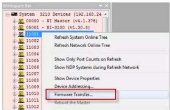
FIG. 14 NetLinx Studio - Online Tree tab Device Context Menu
This action invokes the Send To NetLinx Device dialog, with the Device field pre-populated with the selected device's device number ("11001" in FIG. 15):
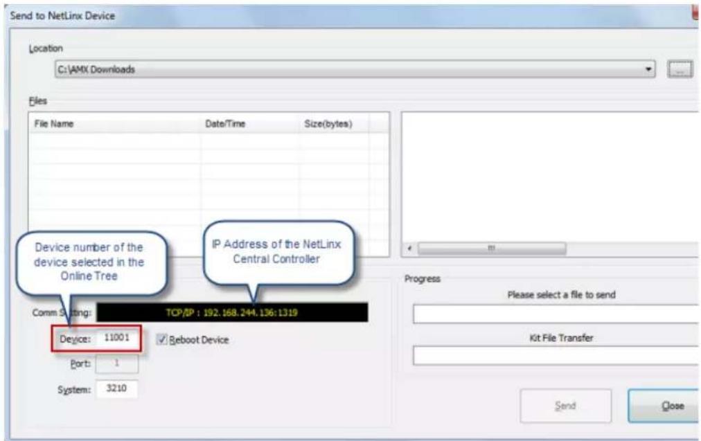
FIG. 15 NetLinx Studio - Send To NetLinx Device dialog,
- Under Location (at the top of this dialog), click the Browse button (...) to locate and select the directory to which the Firmware file was saved.
- The firmware file(s) detected in the specified directory are listed in the Files window (FIG 16):
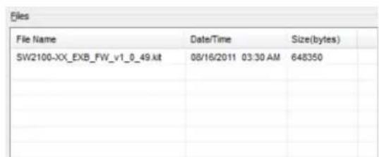
FIG. 16 Send To NetLinx Device dialog - Files window indicating a firmware (kit) file
- Click to select the firmware file that will be transferred, and to display the selected file's Description (FIG. 17):
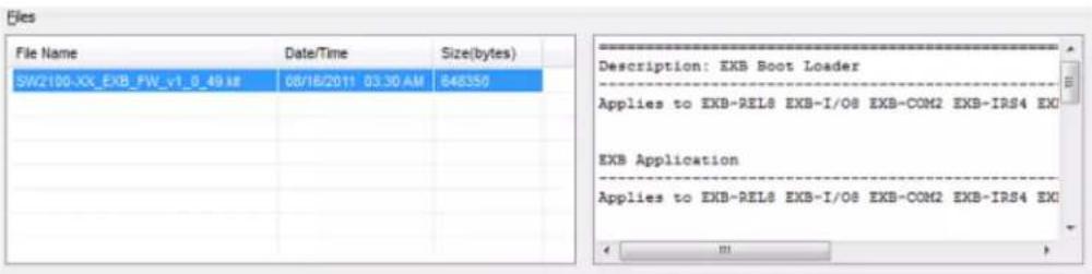
FIG. 17 Send To NetLinx Device dialog - Firmware file selected and Description text displayed
- Verify that the Reboot Device option is selected (default setting):
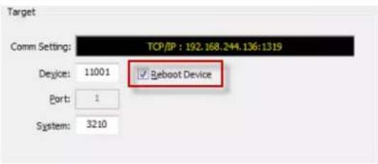
FIG. 18 Send To NetLinx Device dialog - Firmware file selected and Description text displayed
- Click Send to initiate the file transfer (FIG 19):
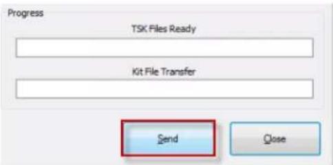
FIG. 19 Send To NetLinx Device dialog - Send button
- The progress of the file transfer and device upgrade are indicated in the Progress bars (FIG. 20):
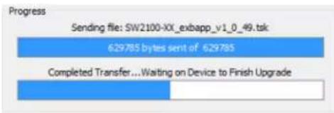
FIG. 20 Send To NetLinx Device dialog - Progress Bars
- Once the transfer is complete and the target device has rebooted, click Close to close the Send To NetLinx Device dialog.
NOTE: The Send To Device dialog can also be accessed via the Tools menu (Tools > Firmware Transfers > Send To NetLinx Device). Note that when the dialog is accessed via the Tools menu, the Device number must be manually entered into the Device field. Otherwise, the preceding instructions for selecting the appropriate *kit file, and initiating the file transfer apply.
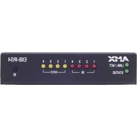
- IMPORTANT SAFETY INSTRUCTIONS
- COPYRIGHT NOTICE
- LIABILITY NOTICE
- AMX WARRANTY AND RETURN POLICY
- Table of Contents
- ICSLan Device Control Boxes 8
- Installation 12
- Network Configuration 14
- EXB-COM2 20
- NetLinx Programming 32
- EXB-REL8 33
- Connections and Wiring 34
- NetLinx Programming 34
- NetLinx Send Commands 35
- SEND\_STRING Escape Sequences.... 45
- Appendix A: Terminal (Telnet) Commands 46
- Overview 46
- Establishing a Terminal Connection via Telnet 46
- Telnet Username and Password 46
- Telnet Commands 47
- Notes on Specific Telnet Clients.... 52
- ICSLan Device Control Boxes
- Overview
- Common Features
- LAN/PoE Port
- Detailed LED Behavior
- Installation
- Mounting Options (Rack Trays and Mounting Brackets)
- AVB-VSTYLE-SURFACE-MNT (FG1010-722)
- AVB-VSTYLE-RMK (FG1010-720)
- AVB-VSTYLE-RMK-FILL-1U (FG1010-721)
- AVB-VSTYLE-POLE-MNT (FG1010-723)
- SAFETY INSTRUCTIONS
- Preparing/Connecting Captive Wires
- Network Configuration
- DHCP Mode
- TCP/IP Address Configuration
- Telnet IP Configuration Commands
- Master Connection Modes
- TCP vs. UDP
- URL vs. NDP vs. Auto
- Factory Default Parameters
- Device IDs
- Using the ID Pushbutton
- Using "Identify Mode" to Set the Device Address on the EXB Modules
- Toggling Between Static and DHCP IP Addressing
- Performing a Factory Reset
- Resetting the Unit to the Factory Default Firmware Image
- Programming the EXB Modules
- EXB-COM2
- EXB-COM2 Product Specifications
- Connections and Wiring
- LAN/PoE Port (RJ45)
- Port 1 (Multi-Protocol COM Port)
- Port 2 (RS-232 only)
- NetLinx Programming
- EXB-COM2 Port Assignments
- EXB-COM2 SEND\_COMMANDs
- SEND\_STRING Escape Sequences
- Telnet commands
- EXB-I/08
- EXB-I/08 Product Specifications
- Port 1 (I/O 1-8)
- EXB-I/08 SEND\_COMMANDs
- EXB-IRS4
- EXB-IRS4 Product Specifications
- IR/Serial Port Bank (Ports 1-4)
- Input Port Bank
- Input Linking
- Unlinked Mode (Default)
- Linked Mode
- Input Pin
- Entering/Exiting Linked Mode
- Linked Modes
- EXB-IRS4 SEND\_COMMANDs
- EXB-MP1
- EXB-MP1 Product Specifications
- Port 1 (RS-232 only)
- Port 2 (I/O)
- Port 3 (IR-TX/Serial)
- Port 4 (IR-RX)
- EXB-MP1 SEND\_COMMANDs
- EXB-REL8
- EXB-REL8 Product Specifications
- Port 1 (Relay Connector)
- EXB-REL8 SEND\_COMMANDs
- NetLinx Send Commands
- Appendix A: Terminal (Telnet) Commands
- Establishing a Terminal Connection via Telnet
- Telnet Username and Password
- Additional Notes
- Setting a Telnet Username and Password
- Notes on Specific Telnet Clients
- Windows Client Programs
- Linux Telnet Client
- Enabling / Disabling Telnet on EXB Modules
- Appendix B: Upgrading Firmware
- Firmware Upgrades
- Downloading the Latest Firmware from www.amx.com
- Upgrading Firmware via NetLinx Studio
- Identifying the Current Firmware Version of the EXB Unit
- Transferring a Firmware File to an EXB Unit
Brand : AMX
Model : EXB-REL8
Category : Electronic control box