
IPX-300 - Desk Phone Planet - Free user manual and instructions
Find the device manual for free IPX-300 Planet in PDF.


| Product Type | Internet Telephony PBX System (IPX-300) / Wi-Fi Internet Telephony PBX System (IPX-300W) |
| Dimensions (W x D x H) | 180 x 110 x 25 mm |
| Power Requirement | 12V DC |
| Max User Registrations | Up to 100 nodes (SIP IP phones/ATA/FXO gateways) |
| Max Concurrent Calls | 30 |
| Voice Codecs Supported | G.711, G.723, G.726, G.729, GSM, iLBC |
| Call Control Protocol | SIP 2.0 (RFC3261), SDP (RFC 2327), Symmetric RTP |
| PBX Features | Auto Attendant (AA), Interactive Voice Response (IVR), Voicemail (VM) with email forwarding, Call Detailed Record (CDR), Web Management, Call/Pickup Groups, Hunt Groups |
| Call Features | Caller ID, Call Hold, Call Waiting, Call Transfer, Call Forward (Always/Busy/No Answer), Call Pickup, Call Park, Music on Hold, Three-way Conference (with supported phones) |
| Network Interfaces | LAN: 1x RJ-45 10/100Base-TX; WAN: 1x RJ-45 10/100Base-TX (both models); Wireless: IEEE 802.11b/g (IPX-300W only) |
| Internet Sharing & Routing | NAT/Bridge mode, DHCP Server, Static Route, DMZ, Virtual Server, Port Trigger, Packet/URL Filter, UPnP, DDNS |
| Wireless Security (IPX-300W) | 64/128-bit WEP, WPA, WPA-PSK, WPA2, WPA2-PSK, WPA/WPA2 mix, WPA-PSK/WPA2-PSK mix |
| Management | Web-based GUI (HTTP), Firmware upgrade via web, Backup & Restore configuration |
| LED Indicators | PWR, WAN (LNK/ACT), LAN (LNK/ACT); IPX-300W additionally has WLAN (LNK/ACT) |
| Operating Temperature | 0°C to 40°C, 0-90% humidity |
| Certifications | CE, FCC Class B |
| Maintenance & Cleaning | Keep in a dry, dust-free environment. Clean exterior with a soft, dry cloth. Do not use liquids or aerosols. |
| Security Features | Intrusion Detection, Drop Malicious Packet, Access Control (MAC filtering), URL Filter, Packet Filter |
| Spare Parts & Repairability | No user-serviceable parts. Contact PLANET Technology support for repairs or replacement. |
Frequently Asked Questions - IPX-300 Planet
User questions about IPX-300 Planet
0 question about this device. Answer the ones you know or ask your own.
Ask a new question about this device
Download the instructions for your Desk Phone in PDF format for free! Find your manual IPX-300 - Planet and take your electronic device back in hand. On this page are published all the documents necessary for the use of your device. IPX-300 by Planet.
USER MANUAL IPX-300 Planet
Internet Telephony PBX System
IPX-300 Series
User's manual
Version 1.0.2
Copyright
Copyright (C) 2009 PLANET Technology Corp. All rights reserved.
The products and programs described in this User's Manual are licensed products of PLANET Technology, This User's Manual contains proprietary information protected by copyright, and this User's Manual and all accompanying hardware, software, and documentation are copyrighted.
No part of this User's Manual may be copied, photocopied, reproduced, translated, or reduced to any electronic medium or machine-readable form by any means by electronic or mechanical. Including photocopying, recording, or information storage and retrieval systems, for any purpose other than the purchaser's personal use, and without the prior express written permission of PLANET Technology.
Disclaimer
PLANET Technology does not warrant that the hardware will work properly in all environments and applications, and makes no warranty and representation, either implied or expressed, with respect to the quality, performance, merchantability, or fitness for a particular purpose.
PLANET has made every effort to ensure that this User's Manual is accurate; PLANET disclaims liability for any inaccuracies or omissions that may have occurred.
Information in this User's Manual is subject to change without notice and does not represent a commitment on the part of PLANET. PLANET assumes no responsibility for any inaccuracies that may be contained in this User's Manual. PLANET makes no commitment to update or keep current the information in this User's Manual, and reserves the right to make improvements to this User's Manual and/or to the products described in this User's Manual, at any time without notice.
If you find information in this manual that is incorrect, misleading, or incomplete, we would appreciate your comments and suggestions.
CE mark Warning
The is a class B device, In a domestic environment, this product may cause radio interference, in which case the user may be required to take adequate measures.
WEEE Warning

To avoid the potential effects on the environment and human health as a result of the presence of hazardous substances in electrical and electronic equipment, end users of electrical and electronic equipment should understand the meaning of the crossed-out wheeled bin symbol. Do not dispose of WEEE as unsorted municipal waste and have to collect such WEEE separately.
Trademarks
The PLANET logo is a trademark of PLANET Technology. This documentation may refer to numerous hardware and software products by their trade names. In most, if not all cases, their respective companies claim these designations as trademarks or registered trademarks.
Revision
User's Manual for PLANET Internet Telephony PBX System:
Model: IPX-300/IPX-300W
Rev: 1.02 (March, 2009)
Part No. EM-IPX300 Series V1.02
TABLE OF CONTENTS
Chapter 1 Introduction......6
Overview......6
Package Content 8
Physical Details 8
Front Panel Indicators....8
Rear Panel Indicators....9
Chapter 2 Preparations & Installation.... 10
Physical Installation Requirement....10
Network Interface quick configurations....11
Chapter 3 IP PBX Setup .... 16
SIP Basic Setting 16
User Extensions Setup....18
SIP Trunk 20
Gateway Trunk 22
Trunk Group 22
Dialing Rules....24
Attendant Extension 25
Attendant Message 26
Attendant Time....27
Record Auto Attendant 28
Upload Voice File 29
Call Parking....29
General Setting....30
Hunt Group Setting....33
Call Screen....35
Chapter 4 Network Setup.... 38
WAN & LAN Setup....38
DHCP 43
WLAN Setting (For IPX-300W)....45
Access Policy (For AP and WISP&AP mode) 52
Static Route....53
NAT 54
Packet Filter....57
URL Filter....59
Security 59
UPnP....60
Call Out Block List....60
SNTP 62
Chapter 5 Management 63
Admin Account....63
Date & Time 64
Ping Test 65
How to use Call Parking function....70
Appendix B....71
How to use Call Pick-up function....71
Appendix C....72
How to record Sound and replacement Sounds package....72
Appendix D....76
Record Voice Guide Process 76
Appendix E....77
Voice Communication Samples 77
IP Phone and Wi-Fi Phone register to IPX-300W 77
IP Phone and Wi-Fi Phone make off-Net calls via Gateway....81
IP Phone and Wi-Fi Phone make external SIP Proxy calls via SIP Trunk......86
Appendix F 88
IPX-300 Series Specifications 88
Appendix G....90
IP PBX Voice Sounds....90
Overview
PLANET IPX-300/IPX-300W IP PBX telephony systems ("IP PBX" in the following term) are designed and optimized for the small business in daily communications. It can support up to 100 user registrations and easy to install and manage a fully working system with the convenience and cost advantages. The future IP PBX telephony system offers all of the essential features of telephony which is required by small business users for their telecommunication/data needs.
The IP PBX series are the feature-rich SIP based IP PBX telephony system that integrates NAT functions to make it perfect for small business usage. The IP PBX integrates traditional PBX system functions and provides many advanced functions including voice mail to email, web management etc. Designed to run on a variety of VoIP applications, the IP PBX provide IP-based communications, voice conferencing, call detailed record (CDR), centralized Auto-Attendant (AA), and Interactive Voice Responses (IVR). The IP PBX utilizes standard PSTN / GSM lines via the interfaces of FXO / GSM gateway to become a feature-rich IP PBX telephony system that supports seamless communications among existing local calls, SIP-based endpoints including low cost of long distance service, telephone number portability and one network for both voice and data.
With a built-in IEEE 802.11b/g wireless AP / CPE, the Wi-Fi IP PBX (IPX-300W) offers wireless connectivity via 54Mbps data transmissions. Users may integrate PLANET IP Phone VIP-154T series, VIP-155PT/ 350PT/ 550PT, the VIP-156/ 157/ 158/ 161W of ATA (analog telephone adapter) series, the VIP-191/ 192 of Wi-Fi Phone, and Gateway series VIP-281/ 281GS/ 480 to build up the VoIP network deployment in minutes.
IP PBX Features
- PBX Features
- Automated Attendant (AA)
- Interactive Voice Responses (IVR)
- Voicemail support (VM)
- Voicemail to E-Mail
- Call Detailed Record (CDR)
- User Management via Web Browser
- Call/Pickup Group
- Display 100 Registered User's Status: Unregistered / Registered / On-Call
- Call Features
- Call Forward Immediate
- Call Forward on Busy
- Call Forward on No Answer
- Call Pickup / Call Park
- Caller ID
- Music on Hold / Music on Transfer
- Call Transfer / Call Hold / Call Waiting
- Three-way conference with feature phones (VIP-154T series, VIP-155PT/ 350PT/ 550PT and VIP-156/ 157/ 158/ 161W series)
- Router/Firewall Features
- DHCP Server for LAN Users
- Access Control / URL Filter
- Virtual Server / DMZ / Port Mapping
- Static Route
- Pass-through
- UPnP
• Wireless Features (IPX-300W)
- IEEE 802.11b/ 802.11g
- AP / AP-Client / WISP & AP Mode
- 64/128 bits WEP Date Encryption
- WPA/ WPA-PSK/ WPA2/ WPA2-PSK/ Mix Mode
- WPAPSK/ WPS2PSK Mix Mode
Package Content
The contents of your product should contain the following items:
Internet Telephony PBX system unit
Power Adapter
Quick Installation Guide
User's Manual CD
Physical Details
The following figure illustrates the front/rear panel of IP PBX.
Front Panel Indicators

Figure 1-1. Front Panel of IPX-300

Figure 1-2. Front Panel of IPX-300W
| Front Panel LED State Descriptions | ||
| PWR | OnOff | PBX Power ONPBX Power OFF |
| WAN Port | OnFlashingOff | PBX network connection establishedData traffic on cable networkWaiting for network connection |
| LAN Port | OnFlashingOff | LAN is connected successfullyData is transmittingEthernet not connected to PC |
| WLAN Port (IPX-300W only) | OnFlashingOff | WLAN is connected successfullyData is transmittingEthernet not connected to PC |
Table1-1. Front Panel description of IP PBX

Figure 1-3. Rear Panel of IPX-300

Figure 1-4. Rear Panel of IPX-300W
| 1 | 12V | DQV DC Power input outlet | |
| 2 | Reset | The reset button, when pressed, resets the IP PBX without the need to unplug the power cord. | |
| 3 | WAN | uto negotiating Fast EthernetThe WAN por 10/100Base-T networks. This port allows your IP PBX to be connected to an Internet Access device, e.g. router, cable modem, ADSL modem, through a CAT.5 twisted pair Ethernet cable. | |
| 4 | LAN | The LAN port allows your PC or Switch/Hub to be connected to the IP PBX through a CAT.5 twisted pair Ethernet cable. | |
| 5 | External Antenna 2db (IPX-300W only) | Used to Wirelessly Connect to 802.11b/g networks 802.11b: 11/5.5/2 Mbps 802.11g: 54/48/36/24/19/12/6Mbps |
Table 1-2. Rear Panel description of IP PBX
Preparations & Installation
Physical Installation Requirement
This chapter illustrates basic installation of IP PBX
• Network cables. Use standard 10/100BaseT network (UTP) cables with RJ45 connectors.
- TCP/IP protocol must be installed on all PCs.
For Internet Access, an Internet Access account with an ISP, and either of a DSL or Cable modem (for WAN port usage)
Administration Interface
PLANET IP PBX provides GUI (Web based, Graphical User Interface) for machine management and administration.
Web configuration access:
To start IP PBX web configuration, you must have the web browsers installed on computer for management
• Microsoft Internet Explorer 6.0.0 or higher with Java support
Default LAN interface IP address of IP PBX is 192.168.0.1. You may now open your web browser, and insert 192.168.0.1 in the address bar of your web browser to logon IP PBX web configuration page.
IP PBX will prompt for logon username/password, please enter: admin / 123 to continue machine administration.
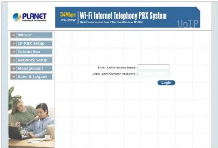
Figure 2-1. Input prompt
Note
In order to connect machine for administration, please locate your PC in the same network segment (192.168.0.x) of IP PBX. If you're not familiar with TCP/IP, please refer to related chapter on user's manual CD or consult your network administrator for proper network configurations.
Network Interface quick configurations
Wizard for Quick Setup of the IP PBX, after finishing the authentication, please click "Wizard" to enter quick start:
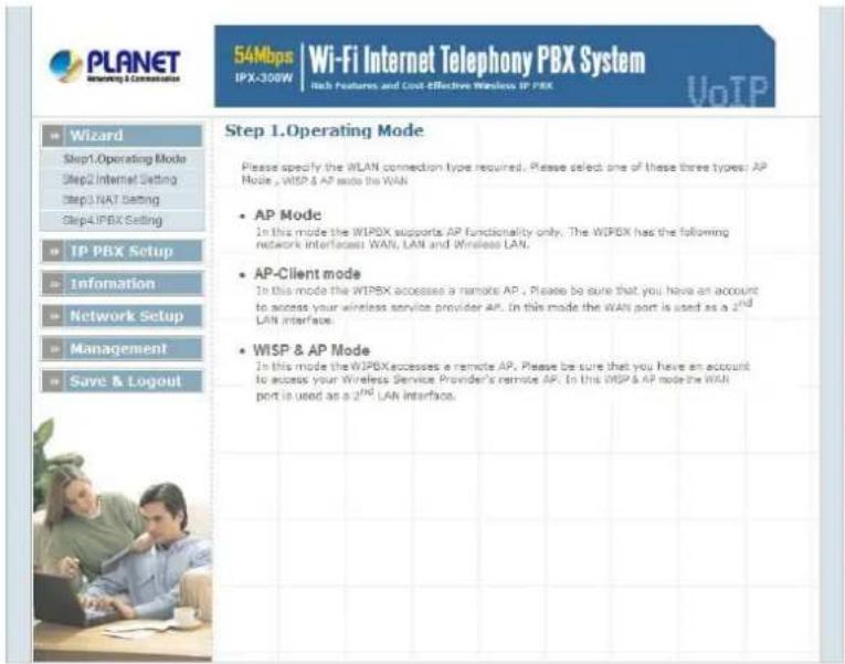
Figure 2-2. Wizard-Operating Mode settings
Step1. Operation Mode (For IPX-300W)
For most users, Internet access is the primary application. The IP PBX supports the WAN, LAN and WLAN interface for Internet access and remote access. When you click "Operation Mode" from within the Wizard Setup, the following setup page will be show.
Three WLAN modes of operation are available for Internet Access:
AP Mode:
In this mode the IP PBX supports AP functionality only. The IP PBX has the following network interfaces: WAN, LAN and Wireless LAN.
AP-Client Mode:
In this mode the IP PBX accesses a remote AP. Please be sure that you have an account to access your wireless service provider AP. In this mode the WAN interface is used a 2nd LAN interface.
WISP & AP Mode :
The IP PBX must access remote AP .Please be sure that have account to access from remote AP. In this WISP & AP mode the network interface will change from WAN port to LAN port and all of network access will through by remote AP.
Step2. Internet Setting (AP Mode)
WAN Setting
| NAT Mode | Network Address Translation (NAT) serves connecting multiple computers to the Internet using one IP address. |
| Bridge Mode | Bridge mode serves to connect a local area network (LAN / Wireless) to another local area network that uses the same protocol. |
| WAN Port IP Assignment | Three methods are available for Internet Access. Static IP / DHCP / PPPoE type for your select .you should refer to “Network Setting” in user menu. |
Table 2-1. WAN description of IP PBX
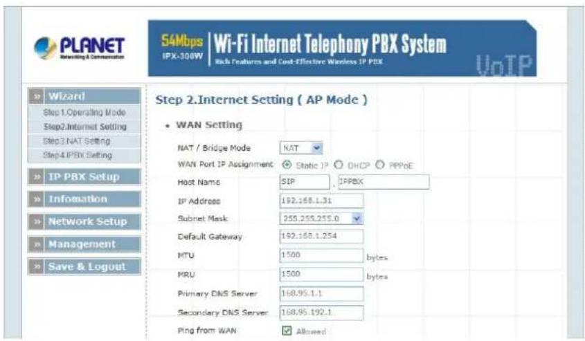
Figure 2-3. Wizard-Internet settings
AP Setting (For IPX-300W)
For configuring correctly the WLAN port in client mode. the below instructions will provide a quick start. It is advised if possible to use the simplest network settings for first try.
For making sure the IP PBX is connecting to your wireless router (AP). You need to set up the following: SSID, Frequency Channel, Authentication method and Encryption parameters (Type/Encryption length/Keys.)
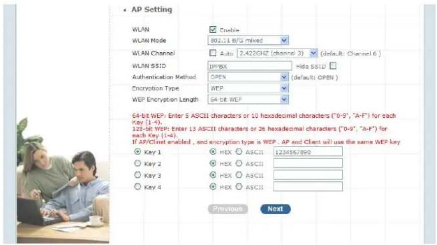
Figure 2-4. Wizard-AP settings
Step3. NAT Setting
LAN IP Setting
| LAN IP Address | Private IP address for connecting to a local private network. (Default: 192.168.0.1) |
| Subnet Mask | Subnet mask for the local private network (Default: 255.255.255.0) |
| DHCP Server | Enable to open LAN port DHCP server |
| Assigned DHCP IP Address | DHCP server range from start IP to end IP |
| DHCP IP Lease Time | Client to ask DHCP server refresh time, range from 60 to 86400 seconds |
Table 2-2. LAN IP description of IP PBX
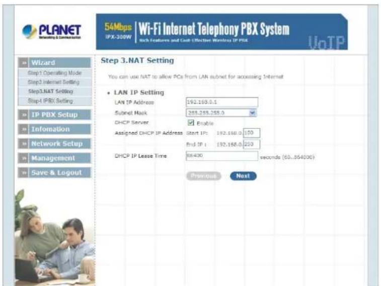
Figure 2-5. Wizard-NAT settings
Step4. IPPBX Setup
The IP PBX allows multiple ITSP providers / User Extensions registration by simply fill-in the required information in the provided table.
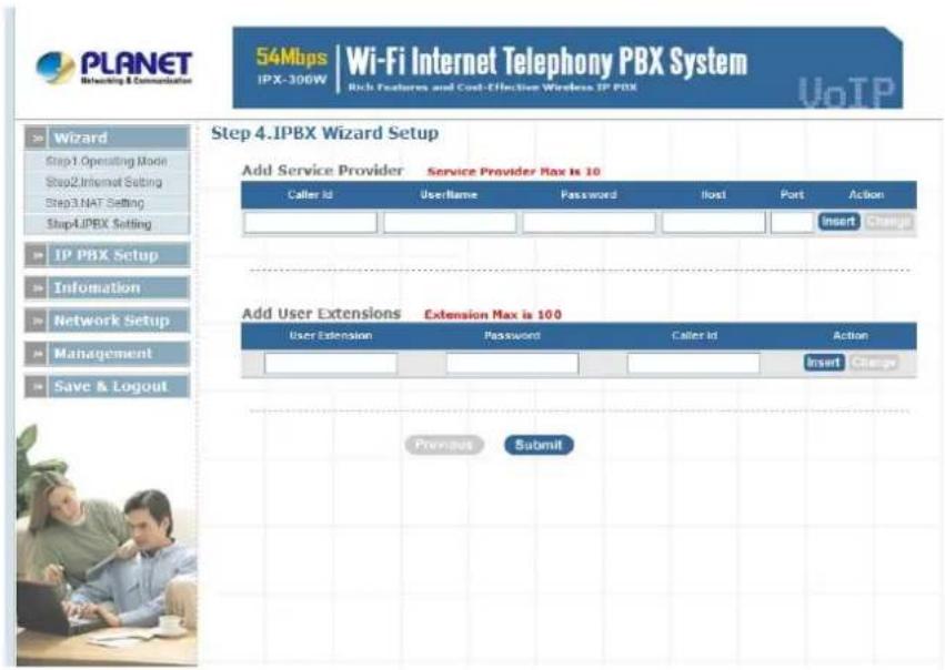
Figure 2-6. Wizard-IP PBX settings
Service Provider:
| Caller ID | Service provider name |
| Username | Input Provider name |
| Password | Input Provider password |
| Host | Input Providers server address |
| Port | Providers server port |
Table 2-3. Service provider description
User Extensions:
| User Extension | Input Extension number |
| Password | Input Extension password |
| Caller Id | Input Extension caller id |
Table 2-4. User extension description
After completing the wizard setup, click "Submit" button, The IP PBX will save configuration and reboot IP PBX automatically, after 50 seconds, you can re-load setting page again.
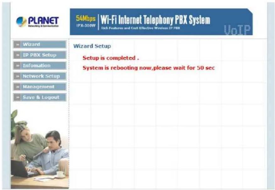
Figure 2-7. Wizard-Rebooting
Note
Please consult your ISP personnel to obtain proper PPPoE/IP address related information, and input carefully. If Internet connection cannot be established, please check the physical connection or contact the ISP service staff for support information.
SIP Basic Setting
SIP (Session Initiation Protocol) is a request-response protocol, dealing with requests from clients and responses from servers. Participants are identified by SIP URLs. Requests can be sent through any transport protocol. SIP determines the end system to be used for the session, the communication media and media parameters, and the called party's desire to engage in the communication. Once these are assured, SIP establishes call parameters at either end of the communication, and handles call transfer and termination.
> SIP Configuration
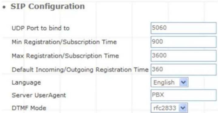
Figure 3-1. SIP configuration settings
| UDP Port to bind to | This is SIP Local Port 5060, if you have any specific reason for change this port. |
| Domain | IP PBX Server's IP address. |
| Max Registration Time | Maximum duration of incoming registration/subscriptions we allow. Default 3600 seconds. |
| Min Registration Time | Minimum duration of registrations/subscriptions. Default 60 seconds |
| Default | |
| Incoming/Outgoing Registration Time | Default duration (in seconds) of incoming / outgoing registration. |
| Language | Set default language for all users. |
| Server UserAgent | Enable you to change the trunk User agent string, Default is PBX. |
| DTMF Mode | Set default DTMF mode for sending DTMF. Default: rfc2833. |
Table 3-1. SIP configuration description
SIP Codecs
The Codec is used to compress the voice signal into data packets. Each Codec has different bandwidth requirement. There are 7 kinds of codec. To determine the priority, selects one codec algorithm from the pull-down menus individually.
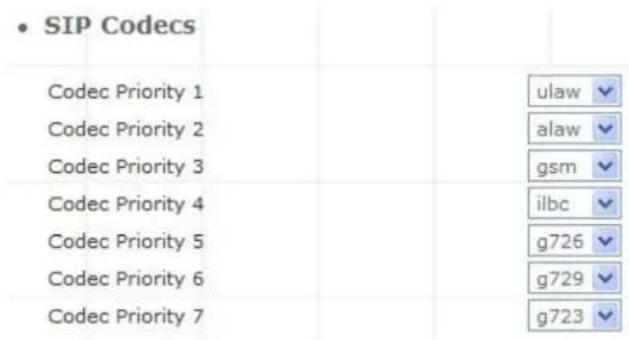
Figure 3-2. SIP codecs settings
Outbound SIP Registrations
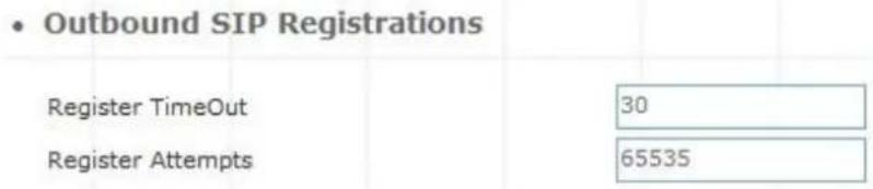
Figure 3-3. Outbound SIP Registrations settings
| Register TimeOut | Retry registration calls at every 'x' seconds (default 20). |
| Register Attempts | Number of registration attempts before we give up; 0 = continue forever. |
Table 3-2. Outbound DIP registration description
NAT Support
The externip, externhost and localnet settings are used if you use IP PBX behind a NAT device to communicate with services on the outside.
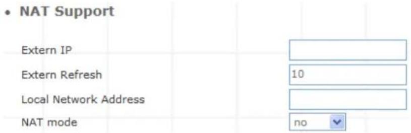
Figure 3-4. NAT support settings
| Extern IP | Address that we're going to put in outbound SIP messages if we're behind a NAT. |
| Extern Refresh | How often to refresh externhost if used. You may specify a local network in the field below. |
| Local Network Address | localnet=192.168.0.0/255.255.0.0; All RFC 1918 addresses are local networkslocalnet=11.0.0.0/255.0.0.0 ; Also RFC1918localnet=171.16.0.0/12 ; Another RFC1918 with CIDR notationlocalnet=168.254.0.0/255.255.0.0; Zero conf local network |
Table 3-3. NAT support description
User Extensions Setup
Extension List
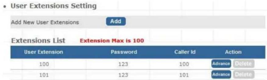
Figure 3-5. User extension settings
| Advance | Click Advance to edit an extension other setting. |
| Delete | Click to delete an extension. |
Table 3-4. User extension description
➢ Advance Setup
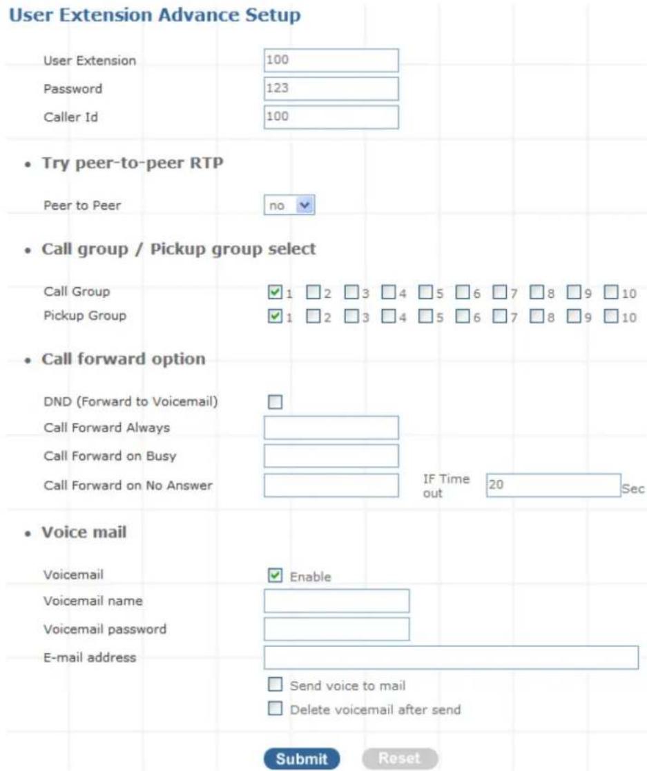
Figure 3-6. Extension advance settings
| User Extension | Input Extension number |
| Password | Input Extension password |
| Caller Id | Input Extension caller id |
Table 3-5. Extension advance description
- Try peer-to-peer RTP :
If select yes, allow RTP transmission to try peer-to-peer for sip extension device between.
- Call group / Pickup group select :
| Call Group | An Extension can set single/multiple call group(s) 1-10 id |
| Pickup Group | An Extension can set single/multiple Pickup group(s) 1-10 id |
Table 3-6. Call / Pickup group description
- Call forward option :
| Call forward always | Input forward always number |
| Call forward on busy | Input forward on busy number |
| Call forward no answer | Input forward no answer number |
| If time out “XXX” sec | This is the maximum number allowed no answer time out used |
Table 3-7. Call forward description
- Voice mail :
| Voice mail select | Enable / Disable voice mail function |
| Voice mail name | Input voice mail name |
| E-Mail address | Input E-mail address |
| Send voice to mail | Enable / Disable send voice to mail |
| Delete voice mail after send | Save / Delete voice mail after send |
Table 3-8. Voice mail description
SIP Trunk
Services Providers Setting allows IP PBX register to different SIP systems and ITSP Services (SIP Trunk).
On the “Providers List”, you can press “Add” to add a new service provider or press “Advance” to edit the information of specific Service Provider or press “Delete” to delete the specified service provider information.

Figure 3-7. Server Providers Setting
Add New Service Providers
Step 1. Press "Add" button to add an new service provider information.

Figure 3-8. Add new service providers
Step 2. Fill in the required information in Service Provider Advance Setup page.
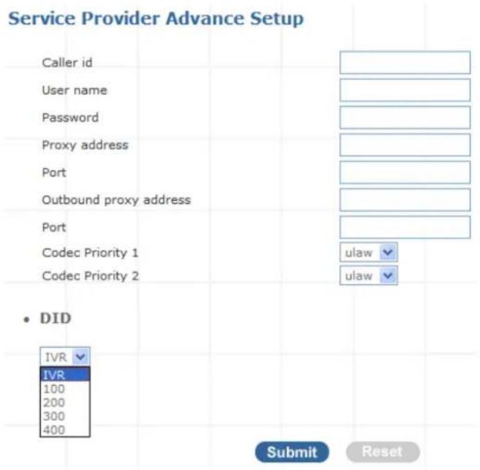
Figure 3-9. Service provider advance setup
| Caller id | The caller ID will be sent between the callee and caller and will be displayed on SIP device LCD panel for identification. |
| User name | User name for authentication |
| Password | User password for authentication |
| Proxy Server address | Assigns the SIP Proxy Server's IP address / Domain name |
| Proxy Server Port | Port number of SIP Proxy Server. Assigns a value from 1024 to 65535, the common default SIP port is 5060. |
| Outbound Proxy Address | Outbound Proxy server's IP address / Domain name. Assign a server's IP / Domain name which is in charge of call-out service. |
| Outbound Proxy Port | Port number of Outbound Proxy Server. Assign a number from 1024 to 65535, the common default SIP port setting is 5060. |
| Codec Priority 1 | Set allow codec priority 1 |
| Codec Priority 2 | Set allow codec priority 2 |
| DID | Choose a direct ring extension or a hunt group or hear the IVR voice prompt, default is “IVR”. (For how to make hunt group please refer “Hunt Group Setting”) |
Table 3-9. Service provider advance setup description
Gateway Trunk
Gateway Trunk Setting allows IP PBX makes VoIP calls to external Gateway by peer-to-peer mode. If the FXO ports of external Gateway have connected with PSTN lines, the user can make outgoing PSTN calls via external Gateway by this function.

Figure 3-10. Gateway Trunk setting
| IP | Destination IP Address is the IP address of the destination Gateway that owns this phone number. |
| Port | Port is port of the destination Gateway use. (Default is 5060) |
Table 3-10. Gateway Trunk setting description
Trunk Group
Trunk Group is defines the leading digit of the call out dialing number through SIP Trunk or Gateway Trunk. The IP PBX will according to the leading digit to determine to use which SIP or Gateway Trunks for outgoing route.

Figure 3-11. Trunk Group setting
Press "more" to show the Service Provider Number under the group.

Figure 3-12. Trunk Group setting - 2
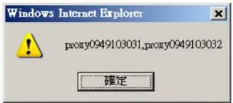
Figure 3-13. Trunk Group more information
Add New Trunk Group
Step 1. Press "Add" button to add an new Group Name information.

Figure 3-14. Add an new Group Name
Step 2. Fill in the required information in Trunk Group Setup page.
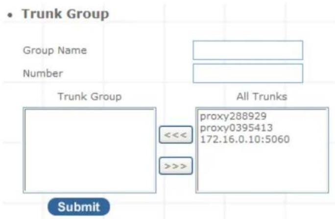
Figure 3-15. Trunk Group Setup
| Group Name | The Trunk Group name |
| Number | If the leading digits are match with this number, IP PBX will delete this number and send out the following digits. |
| All Trunk | It will show all the available SIP Trunks and Gateway Trunks for selection. |
| Trunk Group | Choose the trunk at All Trunk box and press the button to move the activated trunk to Trunk Group box. |
Table 3-11. Trunk Group setting description
Scenario Sample
IP PBX has created two different SIP trunks and one Gateway trunk for outgoing trunks.
| Group Name | Group Number | Number | Action |
| SIP_Trunk_1 | 81 | proxy288929 | Edit Delete |
| SIP_Trunk_2 | 82 | proxy0395413 | Edit Delete |
| FXO_Gateway | 0 | 172.16.0.10:5060 | Edit Delete |
Figure 3-16. Trunk Group sample setting
One-Stage Call:
- If user dials 81123456, this call will hunt SIP_Trunk_1 and send 123456 to call out.
- If user dials 82234567, this call will hunt SIP_Trunk_2 and send 234567 to call out.
- If user dials 0345678, this call will hunt FXO_Gateway and send 345678 to call out.
Two-Stage Call:
- If user dials 81 and hear the dial tone, then dial 123456. This call will hunt SIP_Trunk_1 and send 123456 to call out.
- If user dials 82 and hear the dial tone, then dial 234567. This call will hunt SIP_Trunk_2 and send 234567 to call out.
- If user dials 0 and hear the dial tone, then dial 345678. This call will hunt FXO_Gateway and send 345678 to call out.
Dialing Rules
When want to make VoIP calls through the above SIP Trunk or Gateway Trunk, the user can use the "Dialing Rules" function to simplify the dialing number.
In the "Dialing Rules" settings: Maximum Entries: 100 records
- Dialing Rules

Figure 3-17. Dialing Rules settings
| Phone NO | Phone Number. is the leading digit of the call out dialing number.Phone NO Pattern: “N” single digit from 2 to 9.“z” single digit from 1 to 9.“X” single digit from 0 to 9.“.” unlimited length of digit. |
| Delete Length | Delete Length is the number of digits that will be stripped from beginning of the dialed number. |
| Prefix NO | Prefix NO is the digits that will be added to the beginning of the dialed number. |
Table 3-12. Dialing Rules description
Scenario Sample
- Dialing Rules
Max Rule is 100
| Phone NO. | Delete Length | Prefix NO. | Trunk/Trunk Group | Action | |
| Insert Change | |||||
| 1N | 2 | 77 | proxy888 | Edit Delete | |
| 02. | 0 | 9 | 172.16.0.10:5060 | Edit Delete | |
Figure 3-18. Dialing Rules list
- If user dials 12, this call will hunt SIP_Trunk (proxy888) and send 77 to call out.
- If user dials 02345, this call will hunt Gateway Trunk (172.16.0.10) and send 902345 to call out.
Note
The Dialing Rules function needs to arrange use with Trunk Group function, and it can not be used by itself.
Attendant Extension
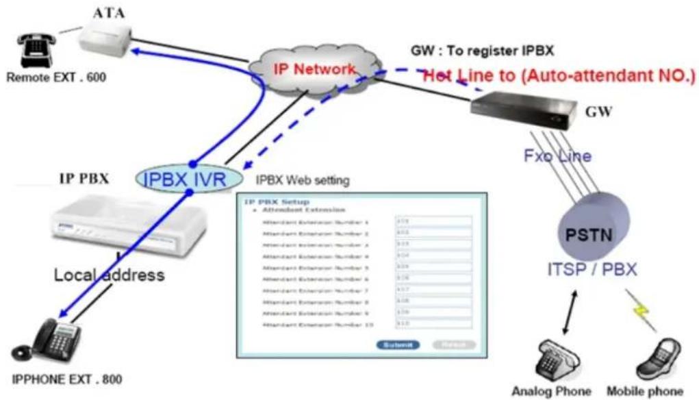
Attendant Extension in IP PBX system helps you to configure internal dial plan for extension setup. It can allow more calls to be handled by IVR from Gateway's FXO, and FXS port. Attendant Extension Provide 10 sets of IVR.
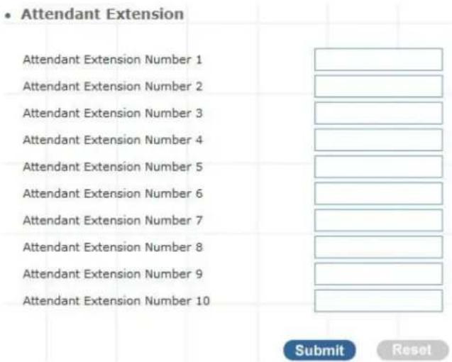
Figure 3-19. Attendant extension settings
The IP PBX will handle incoming Caller ID and show to remote / local registered IP-Phone.
Note
If your Gateway can bypass Mobile/Analog Phone number, The IP PBX will handle incoming caller ID and show to remote / local registered IP-Phone.
> Sample:
flowchart
graph TD
    A["Remote EXT . 600"] --> B["ATA"]
    B --> C["IP Network"]
    C --> D["IP PBX"]
    D --> E["IP PBX IVR"]
    E --> F["IP PBX Web setting"]
    F --> G["IP PBX Setup"]
    G --> H["Antenna Extension Number 1"]
    G --> I["Antenna Extension Number 2"]
    G --> J["Antenna Extension Number 3"]
    G --> K["Antenna Extension Number 4"]
    G --> L["Antenna Extension Number 5"]
    G --> M["Antenna Extension Number 6"]
    G --> N["Antenna Extension Number 7"]
    G --> O["Antenna Extension Number 8"]
    G --> P["Antenna Extension Number 9"]
    G --> Q["Antenna Extension Number 10"]
    C -.-> R["Hot Line to (Auto-attendant NO.)"]
    R --> S["GW"]
    S --> T["PSTN"]
    T --> U["ITSP / PBX"]
    U --> V["Analog Phone"]
    U --> W["Mobile phone"]
    X["Local address"] --> Y["IPPHONE EXT . 800"]
Figure 3-20. Auto-attendant sample
Attendant Message
The Attendant Message on the IP PBX systems, it can auto-answer attendant message setting on the attendant time, IP PBX message can play voice to SIP Trunk and Gateway's FXO, and FXS port.
- Attendant Message
| Message | Service Digit | Action | |||||
| onduty | Advance | ||||||
| offduty | Advance | ||||||
| custom1 | Advance | ||||||
| custom2 | Advance | ||||||
| custom3 | Advance | ||||||
Figure 3-21. Auto-attendant message
• Attendant Message Advance
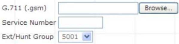
Figure 3-22. Auto-attendant message advance setting
| G.11(.gsm) | You can upload gsm format voice file to IP PBX. |
| Service Number | Associate a dial number with a call group voice instruction to instruct incoming calls. |
| Ext./Hunt Group | Specificity the call group hunting. |
Table 3-13. Attendant Messages setup description
Attendant Time
Defined Attendant Time on the IP PBX systems, it can answer attendant message to match on the attendant time.
- Attendant Time
| Time | Weekdays | Month | Data | Message | Action |
| 08:30-17:30 | Mon-Fri | Jan-Dec | 1-31 | onduty | Edit Reset |
| 00:00-23:59 | Mon-Sun | Jan-Dec | 1-31 | offduty | Edit Reset |
| Edit Reset | |||||
| Edit Reset | |||||
| Edit Reset |
Figure 3-23. Auto-attendant time list
➢ Attendant Time Advance Setting
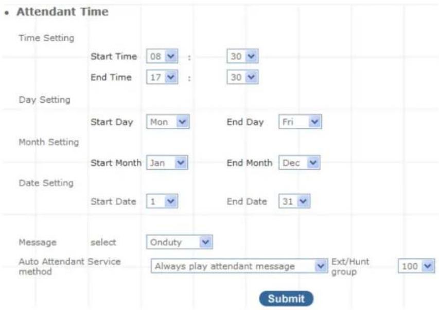
Figure 3-24. Auto-attendant time setting
| Day Setting | Defined Start Day / End Day |
| Time Setting | Defined Start Time / End Time |
| Month Setting | Defined Start Month / End Month |
| Date Setting | Defined Start Date / End Date |
| Message | Select play voice message |
| Auto Attendant method | Service Choose a auto attendant service type, there are 3 types of combination setup. |
| Always play message | attendant After caller hear the voice menu or don't want the caller get any helps Three times, the call will be drops. |
| Always goto group | Ext./Hunt Caller will not hear the voice menu, the call will be directly transferred to the pre-defined group or direct ring extension. |
| User try error goto Ext./Huntgroup | goto After caller hear the voice menu or try error three times, the call will be directly transferred to the pre-defined group or direct ring extension. |
Table 3-14. Attendant Time setup description
Record Auto Attendant
Allow you to record On / Off duty voice menu over a register ip-phone.
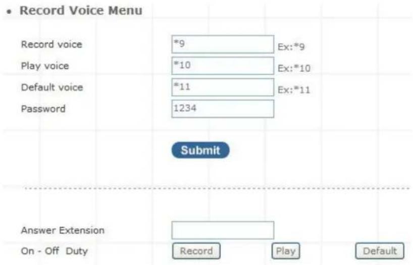
Figure 3-25. Record voice menu settings
Pick up your register IP-Phone handset and press "function key + password" to enter into voice menu guide.
| Record voice | Record your voice menu, Default is *9 |
| Play voice | Play your record voice menu, Default is *10 |
| Default voice | To set default voice menu, Default is *11 |
| Password | This is record / default voice password, Default is 1234 |
Table 3-15. Record voice menu description
Answer Extension enable you to record the customized voice menu remotely from a registered IP-Phone.
Answer extension
Call from registered IP-Phone to record the voice menu.
Table 3-16. Answer extension description
Upload Voice File
This page allows transfer music on hold file or PBX Voice Files from your PC to IP PBX. Please refer to the Appendix C for detail descriptions.
➢ Upload Music Onhold voice file
Click Browse and select your file, then click Upload to finish.

Figure 3-26. On-hold voice uploads
Upload PBX voice file
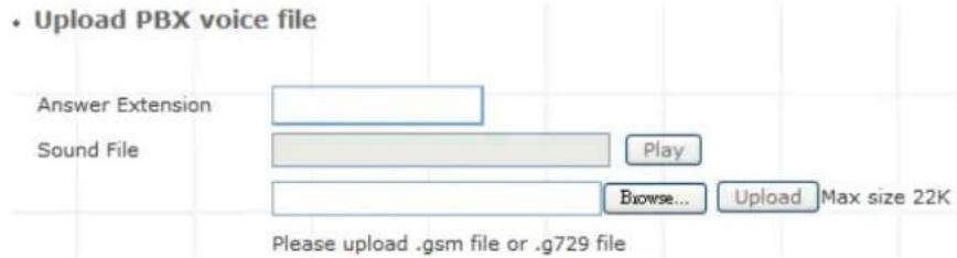
Figure 3-27. Answer extension voice upload
| Answer extension | Call from registered IP Phone to record the voice menu. |
| Sound File | Select G.711 Voice file, then clickplayto your registered device. |
Table 3-17. Voice upload setup description
Call Parking
Build a calling rule for IP Phone to park the calls during the phone conversation.
IP PBX Setup
- Call Parking
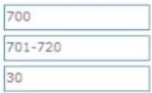
Extension to Dial for Parking Calls
What extension to park calls on
Number of seconds a call can be parked for
Ex:100-150
Submit
Reset
Figure 3-28. Call parking settings
| Extension to Dial for Parking Calls | Set an extension number to dial when need to park the call. Default number is 700. |
| What extension to park calls on | Set the Extension range for call parking retrieving. (Example: '701-720'). |
| Number of seconds a call can be parked for | Set allowed parking time for the parking call. Default is 30/sec. |
| Pickup Extension | Set up a number for IP Phone to retrieve back the call. Default is *8. |
| Timeout for answer on attended transfer | Set a timeout value for answer the transferred call. Default is 30 Sec. |
Table 3-18. Call parking description
General Setting
IP Phone or sip device extension connected IP PBX, extension have call forward / transfer and pickup / voice key ...
➢ Call Forward Key
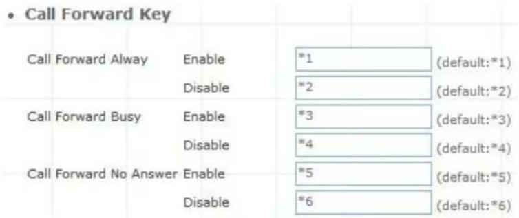
Figure 3-29. Call forward key settings
| Call forward always | Enable: Dial the “ *1 + number ” enable call forward always functionDisable: Dial the “ * 2” disable call forward always function |
| Call forward Busy | Enable: Dial the “ *3 + number ” enable call forward busy functionDisable: Dial the “ * 4 ” disable call forward busy function |
| Call forward no answer | Enable: Dial the “ *5 + number ” enable call forward no answer functionDisable: Dial the “ * 6 ” disable call forward no answer function |
Table 3-19. Call forward description
Transfer Feature
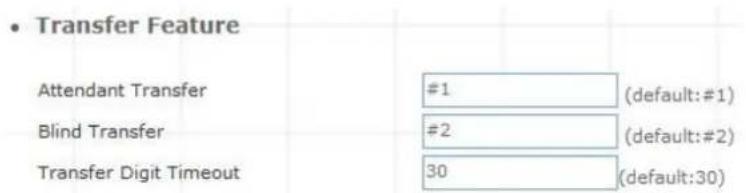
Figure 3-30. Transfer feature settings
| Attendant Transfer | When you attendant transfer fail, you can definition other transfer number |
| Blind Transfer | Blind Transfer, When Ex: Ext 100 call Ext 200, Ext 200 blind transfer to Ext 300, Ignore the Ext.300 status, the Ext.200 will immediately on-hook |
| Transfer Digit time out | Set (Attendant/blind) transfer digit time out sec |
Table 3-20. Transfer feature description
Pickup Key

Figure 3-31. Pickup key settings
| Pickup Extension | Set call pickup (Default is *8) |
Table 3-21. Pickip description
Voice Mail
- Voice Mail
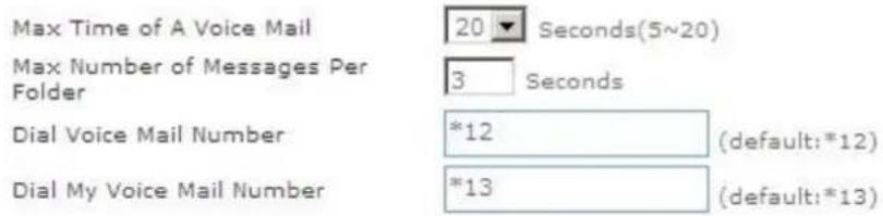
Figure 3-32. Voice mail settings
| Max time of a voice mail | Set a voice mail max time |
| Max number of messages per folder | Max number of voice mail per folder |
| Dial voice mail number | Dial “ *12 “ into voice mail guide |
| Dial my voice mail number | Dial “ *13 + Ext number “ into voice mail guide |
Table 3-22. Voice mail description
SMTP Setting
SMTP is a relatively simple, text-based protocol, where one or more recipients of a message are specified. Input the valid account number, the extension setting voice mail will be been in used.
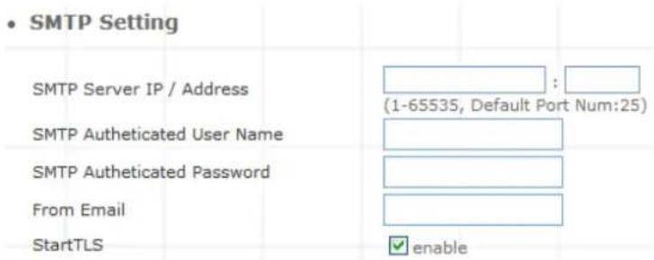
Figure 3-33. SMTP settings
| SMTP server IP / Address | Input server IP / Address |
| SMTP Authentication user name | Input SMTP Authentication user name |
| SMTP Authentication password | Input SMTP Authentication password |
| From Email | Input your Email, if server to check your Email address. |
| StartTLS | When mail transmission, confirms Client to the Server identity. |
Table 3-23. SMTP description
Hunt Group Setting
This setting will allow the caller to choose the specific extension group to answer the phone (e.g. Press 9 for Operator). Every incoming call (from Service Provider or Attendant Extension) will first hear the pre-recorded On / Off Duty Voice for call group options for caller to select.
Users can also setup multiple groups to manage the incoming calls.

Figure 3-34. Hunt Group settings
Press "Add" to add a new Hunt Group;
Press "Edit" to the edit a specified hunt group;
Press "Delete" to delete a specified hunt group;
Add New Hunt Group
Step 1. Press "Add" button to add an new Group Name information.

Figure 3-35. Add an new Group Name
Step 2. Fill in the required information in Hunt Group Setup page.
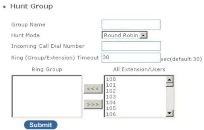
Figure 3-36. Hunt Group setup
| Group Name | Input your group name |
| Hunt Mode | There are 3 modes available: Round Robin / Ring All / Random Mode.1. Round Robin: Take turns ringing each available Extension / Users2. Ring All: Ring all Extension/Users, until any one Extension / Users answer the call.3. Random: Ring random group inside Extension / Users |
| Incoming Call Dial Number | Associate a dial number with a call group voice instruction to instruct incoming calls (e.g. If “20” is associated with Group A, when the caller dial “20”, all extensions under Group A will ring). Default incoming call dial number is empty. |
| Ring (Group/Extension)Timeout | Setup a timeframe to control the call group hunting timeout. Default setting is 30 sec. |
Table 3-24. Hunt Group description
To add extension/users to Ring group
Step 1. Select your extension
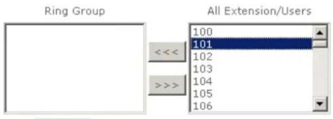
Figure 3-37. Add Extension/User
Step 2. Press <<< to add extension/users to ring group.
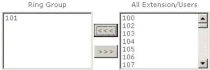
Figure 3-38. Add Extension/User
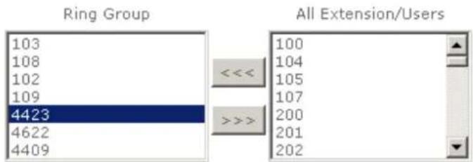
To delete Ring Group inside extension/users
Step 1. Select the extensions
bar
| Ring Group | All Extension/Users | | :--- | :--- | | 103 | 100 | | 108 | 104 | | 102 | 105 | | 109 | 107 | | 4423 | 200 | | 4622 | 201 | | 4409 | 202 |Figure 3-39. Delete Extension/User
Step 2. Press >>> to delete extension/users to ring group.
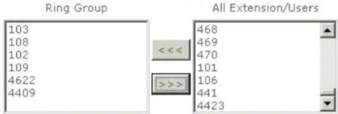
Figure 3-40. Delete Extension/User
Call Screen
Call Screen allows you to block outgoing (for SIP trunk / gateway trunk) calls from SIP extension user number.
IP PBX Setup
• Call Screen Group Setting
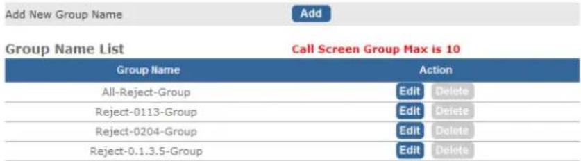
Figure 3-41. Call Screen settings
Add New call group
Step 1. In IP PBX Setup → Call Screen setting → Press "Add" button to add a new Call Screen Group information.
• Call Screen Group Setting
Add New Group Name

Figure 3-42. To add new group name
Step 2. Fill in the required information in call screen group Setup page
• Call Screen (Outgoing call)
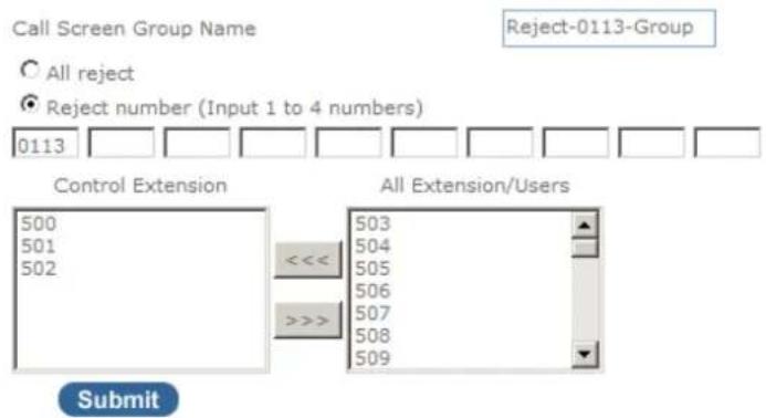
Figure 3-43. Call Screen settings
This sample reject prefix number is 0113 for sip extension 500,501,502 group.
| Call screen group name | Input your call screen group name. |
| All Reject | This option is reject all outgoing call. |
| Reject Number (Input 1 to 4 number) | Input 1 to 4 reject prefix number. |
Table 3-25. Call Screen description
Application
A. Group 2 must be open only to dial local calls and this group wants to use some passwords or keys to dial Long distance.
May I say it also means group only allow to dial local calls, so we reject all long distance call.
For example,
For dialing long distance calls, the number start with 01, 02, 00.
Now extension 200, not able to dial those numbers.
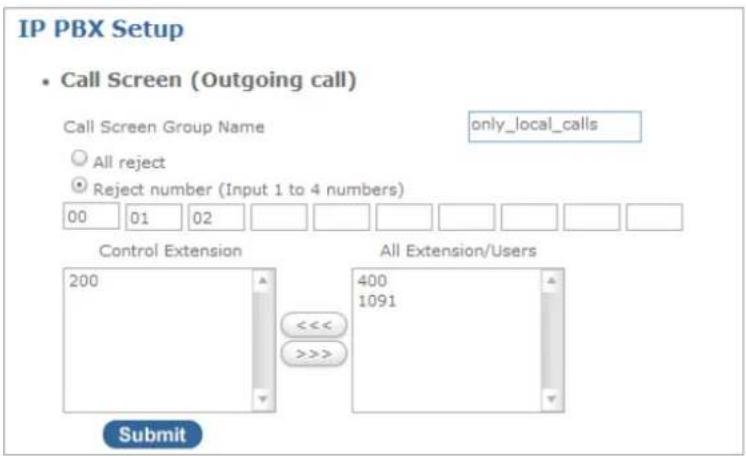
Figure 3-44. Call Screen settings-Application 1
B. This group wants to use some passwords or keys to dial Long distance.
I think this can be easily be done by using long group number.
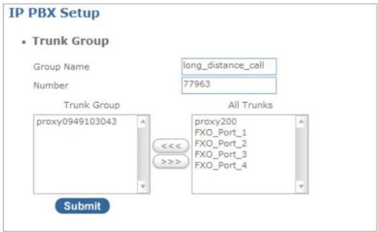
Figure 3-45. Call Screen settings-Application 2
The user now needs to dial 77963(as password) to make call by this trunk
C. Group 3 must be close to all traffic, open only to dial extension numbers.
Select All Reject
Choose the extensions that you don't want it to make calls.
For instance 200
Extension 200 is not able to call out, ONLY able to dial extension numbers.
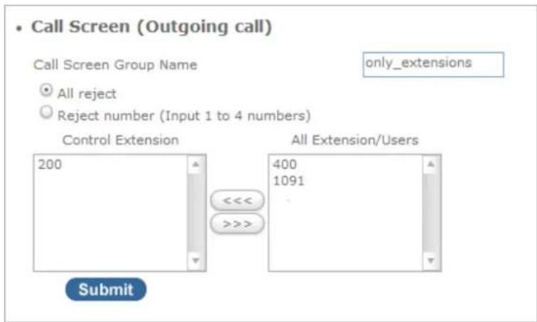
Figure 3-46. Call Screen settings-Application 3
WAN & LAN Setup
WAN (Wide Area Network) is a network connection connecting one or more LANs together over some distance. For example, the means of connecting two office buildings separated by several kilometers would be referred to as a WAN connection. The size of a WAN and the number of distinct LANs connected to a WAN is not limited by any definition. Therefore, the Internet may be called a WAN.
WAN Settings are settings that are used to connect to your ISP (Internet Service Provider). The WAN settings are provided to you by your ISP and often times referred to as "public settings". Please select the appropriate option for your specific ISP.
For most users, Internet access is the primary application. IP PBX supports the WAN interface for internet access and remote access. The following sections will explain more details of WAN Port Internet access and broadband access setup. When you click "WAN & LAN Setup", the following setup page will be shown. Three methods are available for Internet Access.
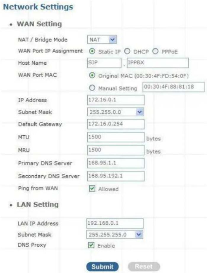
Figure 4-1. Network settings
Static IP
If you are a leased line user with a fixed IP address, enter in the IP address, subnet mask, gateway address, and DNS (domain name server) address(es) provided to you by your ISP. Each IP address entered in the fields must be in the appropriate IP form, which are four IP octets separated by a dot (x.x.x.x). The Router will not accept the IP address if it is not in this format. Example: 168.95.1.2
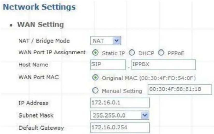
Figure 4-2. WAN-Static IP settings
| IP Address | Check with your ISP provider. |
| Subnet Mask | Check with your ISP provider. |
| Default Gateway | Check with your ISP provider. |
Table 4-1. WAN-Static IP description
DHCP
Dynamic Host Configuration Protocol (DHCP), Dynamic IP (Get WAN IP Address automatically). If you are connected to the Internet through a Cable modem line, then a dynamic IP will be assigned.
Note
WAN port gets the IP Address, Subnet Mask and default gateway IP address automatically, if DHCP client is successful.
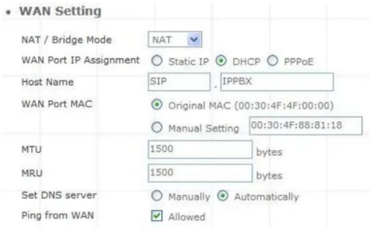
Figure 4-3. WAN-DHCP settings
> PPPoE
Point-to-Point Protocol over Ethernet (PPPoE). Some ISPs provide DSL-based services and use PPPoE to establish communication link with end-users. If you are connected to the Internet through a DSL line, check with your ISP to see if they use PPPoE. If they do, you need to make sure the following items, PPPoE User name: Enter username provided by your ISP. PPPoE Password: Enter password provided by your ISP.
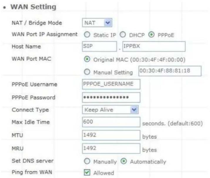
Figure 4-4. WAN-PPPoE settings
Host Name
The Host Name field is optional but may be required by some Internet Service Providers. The default host name is the model number of the device. It is a computer that is connected to a TCP/IP network, including the Internet. Each host has a unique IP address. Assign the domain name or IP address of your host computer. When the host operating system is set up it is given a name. This name may reflect the prime use of the computer. For example, a host computer that converts host names to IP addresses using DNS may be called cvs.IP-PBX.com and a host computer that is a web server may be
called www.IP-PBX.com. When we need to find the host name from an IP address we send a request to the host using its IP address. The host will respond with its host name.
WAN Port MAC
The MAC (Media Access Control) Address field is required by some Internet Service Providers (ISP). The default MAC address is set to the MAC address of the WAN interface in the device. It is only necessary to fill the field if required by your ISP.
The WAN port allows your voice gateway to be connected to an Internet Access Device, e.g. router, cable modem, ADSL modem, through a CAT.5 twisted pair Ethernet Cable. MAC addresses are uniquely set by the network adapter manufacturer and are sometimes called "physical addresses" for this reason. MAC assigns a unique number to each IP network adapter called the MAC address. The MAC address is commonly written as a sequence of 12 hexadecimal digits as follows:
00:3f:4f:88:81:18. The first six hexadecimal digits of the address correspond to a manufacturer's unique identifier, while the last six digits correspond to the device's serial number.
Some Internet service providers track the MAC address of a home router for security purposes. Many routers support a process called cloning that allows the MAC address to be simulated so that it matches one the service provider is expecting. This allows end-user to change their router (and their real MAC address) without having to notify the provider. For example, you could allow packets which have your name server's IP on them, but come from another MAC address (one way of spoofing packets).

Figure 4-5. WAN port MAC settings
MTU and MRU
MTU stands for Maximum Transmission Unit, the largest physical packet size, measured in bytes that a network can transmit. Any messages larger than the MTU are divided into smaller packets before being sent.
MRU stands for Maximum Receiving Unit. The largest physical packet size, measured in bytes that a network can receive. Any messages larger than the MRU are divided into smaller packets before being received.
The key is to be deciding how big your bandwidth pipe is and select the best MTU for your configuration. For example, you have a 33.6 modem, you use a MTU and MRU of 576, and if you have a larger pipe you may want to try 1500.

Figure 4-6. MTU and MRU settings
Note
For Static IP, both MTU and MRU are set to 1500 bytes as default value. For DHCP, both MTU and MRU are set to 1500 bytes as default value. For PPPoE, both MTU and MRU are set to 1492 bytes as default value.
DNS Server
DNS stands for Domain Name System. Every Internet host must have a unique IP address; also they may have a user-friendly, easy to remember name such as www.ippbx.com. The DNS server converts the user-friendly name into its equivalent IP address. The original DNS specifications require that each domain name is served by at least 2 DNS servers for redundancy. When you run your DNS, web, and mail servers all on the same MACHine - if this MACHine goes down, it doesn't really matter that the backup DNS server still works.
The recommended practice is to configure the primary and secondary DNS servers on separate MAChines, on separate Internet connections, and in separate geographic locations.
| Primary DNS Server | 168.95.1.1 |
| Secondary DNS Server | 168.95.192.1 |
Figure 4-7. DNS server settings
| Primary DNS Server | Sets the IP address of the primary DNS server. |
| Secondary DNS Server | Sets the IP address of the secondary DNS server. |
Table 4-2. DNS server description
> Ping From WAN
Ping is a basic Internet program that lets you verify that a particular IP address exists and can accept requests. Ping is used diagnostically to ensure that a host computer you are trying to reach is actually operating.
The default setting is allowed user can ping the host computer from remote site. If you disallow, the host computer doesn't response any user who issues Ping IP address command from any remote sites.
Ping from WAN

Figure 4-8. Ping from wan settings
LAN Setting
These are the IP settings of the LAN (Local Area Network) interface for the device. These settings may be referred to as "private settings". You may change the LAN IP address if needed. The LAN IP address is private to your internal network and cannot be seen on the Internet. The default IP address is 192.168.0.1 with a subnet mask of 255.255.255.0.
LAN is a network of computers or other devices that are in relatively close range of each other. For example, devices in a home or office building would be considered part of a local area network.
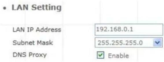
Figure 4-9. LAN settings
| LAN IP Address | Assign the IP address of LAN server, default is 222.222.222.1 |
| Subnet Mask | Select a subnet mask from the pull-down menu, default is 255.255.255.0 |
Table 4-3. LAN description
DNS Proxy
A proxy server is a computer network service that allows clients to make indirect network connections to other network services. The default setting is Enable the DNS proxy server.
DNS Proxy
Enable
Figure 4-10. DNS proxy settings
DHCP
DHCP stands for Dynamic Host Control Protocol. The DHCP server gives out IP addresses when a device is starting up and request an IP address to be logged on to the network. The device must be set as a DHCP client to "Obtain the IP address automatically". By default, the DHCP Server is enabled in the unit. The DHCP address pool contains the range of the IP address that will automatically be assigned to the clients on the network.
DHCP client computers connected to the unit will have their information displayed in the DHCP Client List table. The table will show the Type, Host Name, IP Address, MAC Address, Description, and
Expired Time of the DHCP lease for each client computer. DHCP Server is a useful tool that automates the assignment of IP addresses to numbers of computers in your network. The server maintains a pool of IP addresses that you use to create scopes. (A DHCP scope is a collection of IP addresses and TCP/IP configuration parameters that are available for DHCP clients to lease.) Then, the server automatically allocates these IP addresses and related TCP/IP configuration settings to DHCP-enabled clients in the network. The DHCP Server leases the IP addresses to clients for a period that you specify when you create a scope. A lease becomes inactive when it expires. Through the DHCP Server, you can reserve specific IP addresses permanently for hardware devices that must have a static IP address (e.g., a DNS Server).
An advantage of using DHCP is that the service assigns addresses dynamically. The DHCP Server returns addresses that are no longer in use to the IP addresses pool so that the server can reallocate them to other machines in the network. If you disable this DHCP, you would have to manually configure IP for new computers, keep track of IP addresses so that you could reassign addresses that clients aren't using, and reconfigure computers that you move from one subnet to another. The DHCP Static MAP table lists all MAC and IP address which are active now.
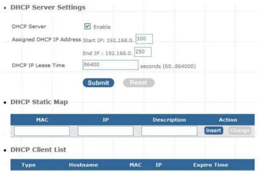
Figure 4-11. DHCP server settings
When you enable the DHCP server, you are able to enter:
| Assigned Address | DHCP IP | Enter the starting IP address for the DHCP server's IP assignment and the ending IP address for the DHCP server's IP assignment. |
| DHCP Time | IP Lease | Assign the length of time for the IP lease, default setting is 86400 seconds. |
Table 4-4. DHCP server description
WLAN Setting (For IPX-300W)
A WLAN is a data communication system that reduces the need for a wired connection, thereby adding new flexibility and convenience to your network. Using electromagnetic waves, WLAN's transmits and receives data over the air, minimizing the need for wired connections and combines data connectivity with user mobility.
AP Mode
Access Point only Mode, The AP functions as a wireless hub to which wireless clients can connect. The clients must make sure that they are configured to match the AP's wireless settings. The AP must be connected to switch or other LAN segment patch cable.
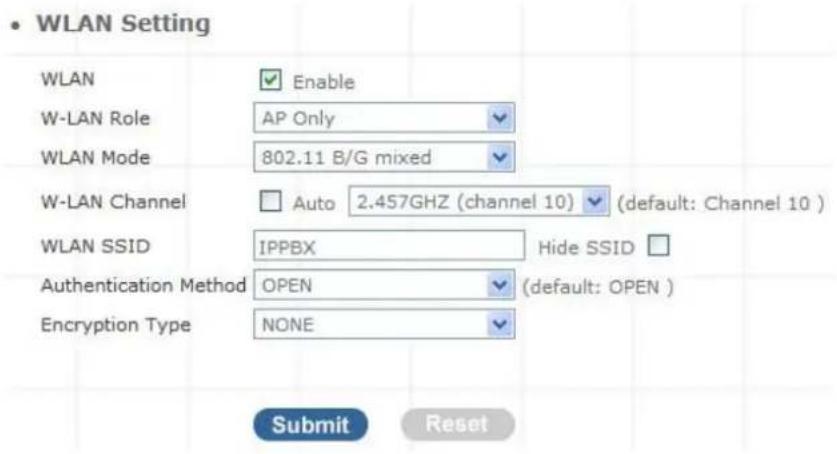
Figure 4-12. AP mode settings
| WLAN | Enable / Disable WLAN Function |
| WLAN Mode | For wireless connected type 802.11 B/G mixed / 802.11b only / 802.11G only |
| WLAN SSID | Wireless stations associating to the access point must have the same SSID. Enter a descriptive name for the wireless LAN.(support 20 ACSII characters) |
| Hide SSID | Hide SSID prevents outside users from joining the network without knowing the wireless Network's ID, default is check SSID. |
| WLAN Frequency | The range of radio frequencies used by IEEE 802.11b/g wireless devices is called a Selection channel. Select a channel ID that is not already in use by a neighboring device. |
| WLAN Frequency Auto | When the users select this option, the IP PBX automatically finds the channel with the least interference and uses that channel for wireless IP PBX transmission. |
Authentication Method
Select OPEN, WPA, WPA-PSK, WPA2, WPA2-PSK, WPA/WPA2 mix mode, WPA-PSK/WPA2-PSK mix mode. Default is OPEN mode.
Table 4-5. AP mode description
Example:
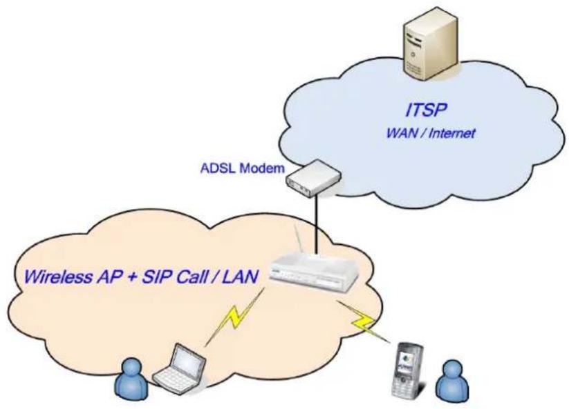
flowchart
graph TD
    A["ADSL Modem"] --> B["ITSP WAN / Internet"]
    C["Wireless AP + SIP Call / LAN"] --> D["Mobile Device"]
    E["Two users"] --> F["Mobile Phone"]
    B --> G["Cloud with Wireless Signal"]
    D --> H["Cloud with Wireless Signal"]
    F --> I["Cloud with Wireless Signal"]
Figure 4-13. AP mode application
AP-Client Mode
In this mode the IP PBX is used to access the Wireless Service Provider network by connecting wirelessly to the remote (Outdoor AP).
When the IPBX operate in AP-Client Mode, the WAN and LAN RJ-45 interface will be configured as a 2 port switch for connecting with 2 PCs for access wireless network
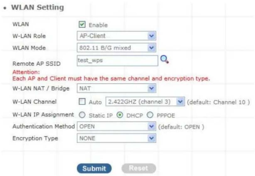
Figure 4-14. AP-client mode settings
| WLAN Mode | For wireless connected type 802.11 B/G mixed/ 802.11b only / 802.11G only |
| Remote AP SSID | Define the same as your Wireless Router uses. |
| Remote AP KEY | Enter the remote AP Authorization Key (WPA-PSK / WPA2-PSK / WPAPSK ,WPA2PSK Mix Mode to Show) |
| W-LAN Channel | Define the same as your Wireless Router uses. |
| W-LAN IP Assignment | 1. DHCP client2. Static IP Address |
| Static IP | Key in the W-LAN IP address, W-LAN Subnet mask and W-LAN Gateway from AP of WISP |
| DHCP Client | When the DHCP Client is enabled, the IP PBX will get the IP Address from Outdoor AP of WISP. |
| PPPoE Client | Enter User Name / Password provided by your ISP, the IP PBX will get the IP Address from Outdoor AP of WISP |
| Remote AP SSID | Define the same as your Wireless Router uses |
| Authentication Method | Define the same as your Wireless Router uses.(OPEN / SHARED Mode) |
| Encryption Type | Define the same as your Wireless Router uses. (OPEN / SHARED Mode) |
| Scan usable network | Select list to remote AP SSID (magnifying glass) |
Table 4-6. AP-Client mode description
- WLAN Setting
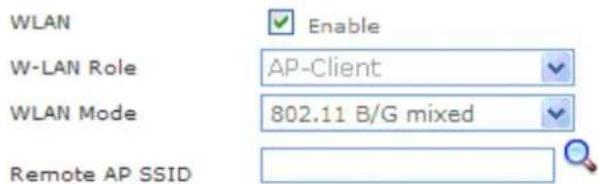
Figure 4-15. AP-Client mode settings
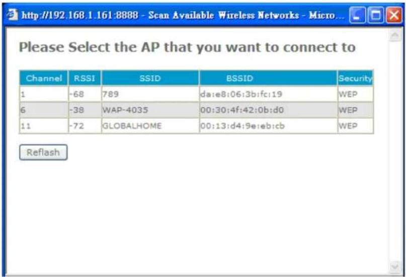
Figure 4-16. Search remote AP list page
Note
After scan and select the Outdoor AP, the channel and encryption method should be set the identical with the remote AP.
Example:
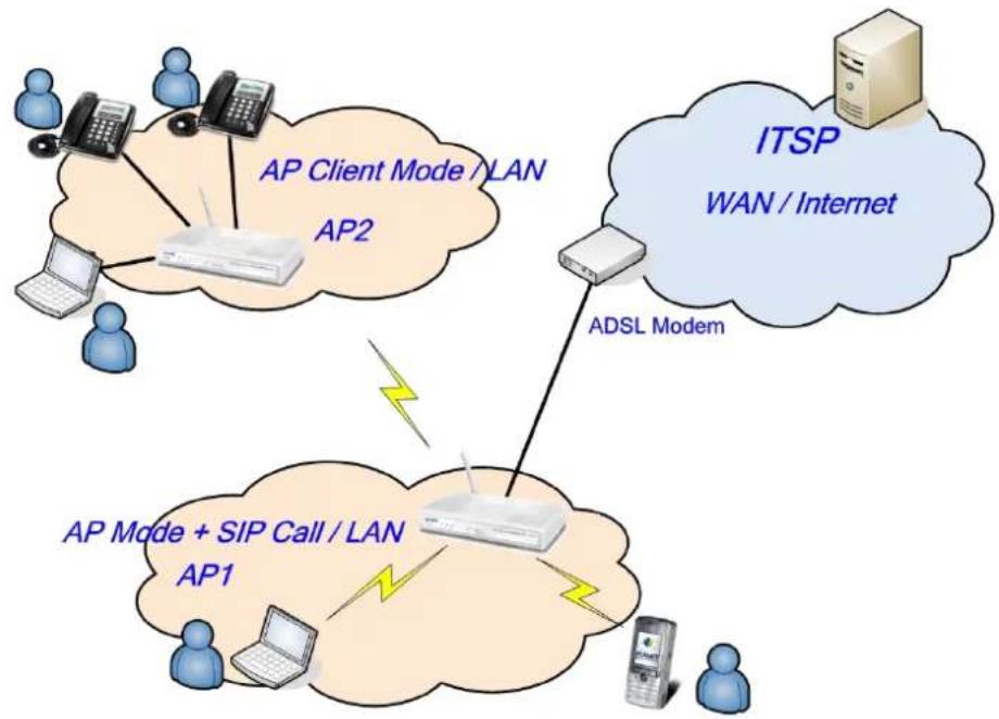
flowchart
graph TD
    A["User Devices"] --> B["AP Client Mode / LAN"]
    B --> C["AP2"]
    C --> D["ITSP WAN / Internet"]
    D --> E["ADSL Modem"]
    E --> F["AP Mode + SIP Call / LAN"]
    F --> G["AP1"]
    G --> H["User Devices"]
    style A fill:#f9f,stroke:#333
    style B fill:#ccf,stroke:#333
    style C fill:#cfc,stroke:#333
    style D fill:#fcc,stroke:#333
    style E fill:#cff,stroke:#333
    style F fill:#ffc,stroke:#333
    style G fill:#cfc,stroke:#333
    style H fill:#fcc,stroke:#333
Figure 4-17. Ap-Client mode application
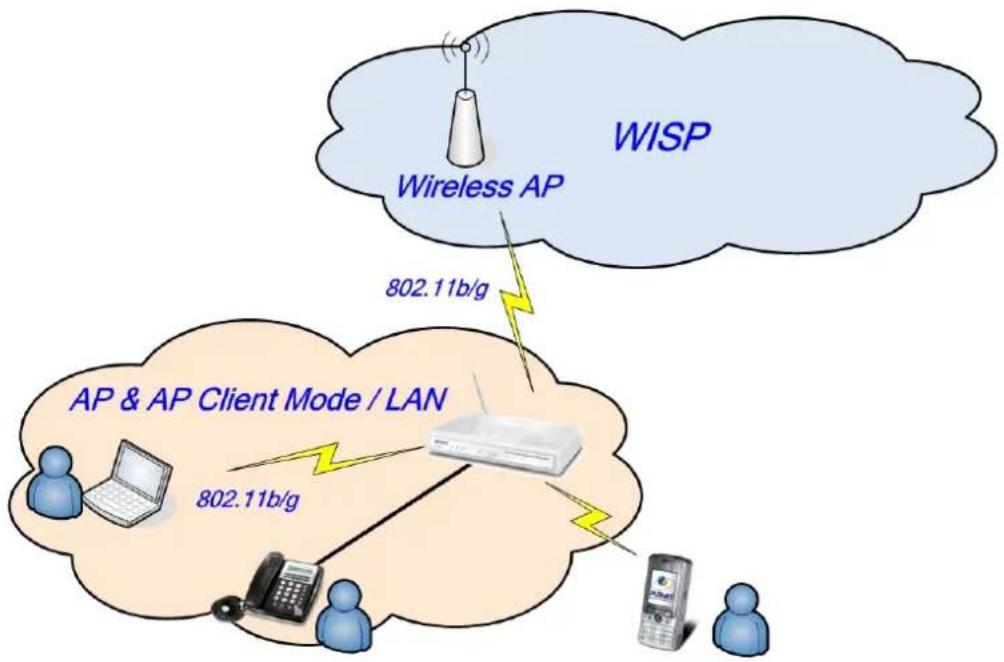
WISP & AP Mode
The IP PBX can operate in AP-Client and access to another (Outdoor) AP. The wireless client needs to have the same SSID, Channel, Encryption settings as the main AP. The user may need to change the default IP to avoid IP conflicts.
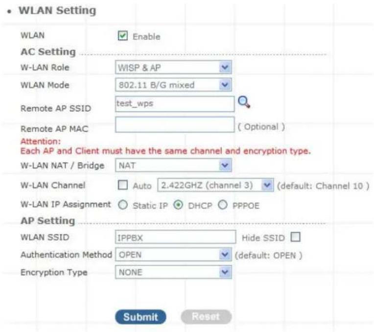
Figure 4-18. WISP & AP mode settings
Note
When IP PBX operates in AP-Client (or WISP & AP) Mode, the WAN and LAN RJ-45 interface will be configured as a 2 port switch for connecting with 2 PCs for access wireless network.
| WLAN Mode | For wireless connected type 802.11 B/G mixed/ 802.11b only / 802.11G only |
| Remote AP SSID | Define the same as your Wireless Router uses |
| Remote AP MAC | Define the same as your Wireless Router uses |
| Remote AP Key | Enter the remote AP Authorization Key (WPA-PSK / WPA2-PSK / WPAPSK ,WPA2PSK Mix Mode to Show) |
| W-LAN Channel | Define the same as your Wireless Router uses |
| W-LAN IP Assignment | 1.DHCP client2.Static IP Address |
| Static IP | Key in the W-LAN IP address, W-LAN Subnet mask and W-LAN Gateway from WISP |
| DHCP Client | When the DHCP Client is enabled, the IP PBX will get the IP Address from Outdoor AP of WISP |
| WLAN SSID | The service set identifier assigned to the wireless network (WLAN). Default SSID is IPPBX |
| Hide SSID | Hide SSID prevents outside users from joining the network without knowing the wireless Network's ID, default is check SSID |
| Authentication Method | Define the same as your Wireless Router uses. (OPEN / SHARED Mode) |
| Encryption Type | Define the same as your Wireless Router uses. (OPEN / SHARED Mode |
Table 4-7. WISP & AP mode description
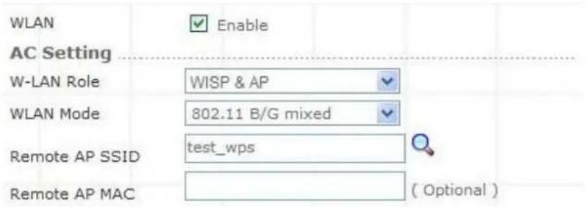
Figure 4-19. WISP & AP mode settings
Scan usable network : Select list to remote AP SSID (magnifying glass)
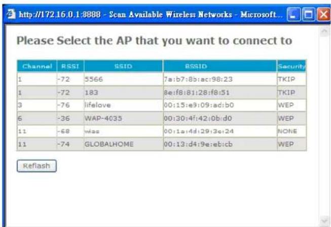
Figure 4-20. Search remote AP list page
Note
After scan and select the Outdoor AP, the channel and encryption method should be identical with the remote AP
Example:
flowchart
graph TD
    A["Wireless AP"] -->|802.11b/g| B["AP & AP Client Mode / LAN"]
    C["WISP"] -->|802.11b/g| B
    B --> D["Client with laptop, phone, and mobile"]
Figure 4-21. WISP & AP mode application
Access Policy (For AP and WISP&AP mode)
Access Policy
In IP PBX security, an access control list is a list of "allow all / Reject all" to an MAC.
Access Control List
MAX MAC List : 64
Table 4-8. Access policy description
Network Settings
- Access Policy Setting
Access Policy Access Control List
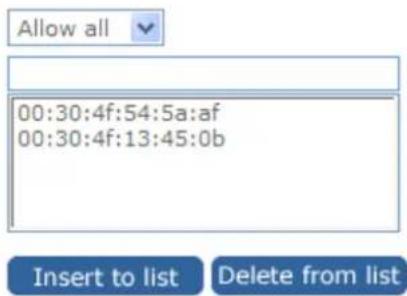
Figure 4-22. Access policy settings
Network Settings
- Access Policy Setting
Access Policy
Access Control List
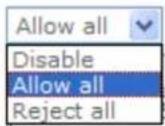
Figure 4-23. Access policy settings
Static Route
Static routes are special routes that the network administrator manually enters into the router configuration for local network management. You could build an entire network based on static routes.
The problem with doing this is that when a network failure occurs, the static route will not change without you performing the change. This could be IP-PBX if the failure occurs when the administrator is not available.
The route table allows the user to configure and define all the static routes supported by the router.
Network Settings
- Static Route

Figure 4-24. Static route settings
| Enable | Enable/Disable the static route. |
| Type | Indicates the type of route as follows, Host for local connection and Net for network connection. |
| Target | Defines the base IP address (Network Number) that will be compared with the destination IP address (after an AND with NetMask) to see if this is the target route. |
| NetMask | The subnet mask that will be AND'd with the destination IP address and then compared with the Target to see if this is the target route. |
| Gateway | The IP address of the next hop router that will be used to route traffic for this route. If this route is local (defines the locally connected hosts and Type = Host) then this IP address MUST be the IP address of the router. |
| Action | Insert a new Static Router entry or update a specified entry. |
Table 4-9. Static route description
NAT
NAT (Network Address Translation) serves three purposes:
- Provides security by hiding internal IP addresses. Acts like firewall.
- Enables a company to access internal IP addresses. Internal IP addresses that are only available within the company will not conflict with public IP.
- Allows a company to combine multiple ISDN connections into a single internet connection.
Network Settings
- NAT Setting
Network Address Translation
IPSec Pass Through
PPTP Pass Through
L2TP Pass Through
SIP ALG
NetMeeting ALG
DMZ
Enable
Enable
Enable
Enable
Enable
Enable
Enable
Submit
Reset
Figure 4-25. NAT settings
NAT Setting
- NAT Setting
Network Address Translation
IPSec Pass Through
PPTP Pass Through
L2TP Pass Through
SIP ALG
NetMeeting ALG
DMZ
DMZ LAN IP
Enable
Enable
Enable
Enable
Enable
Enable
Enable
192.168.0.11
Submit
Reset
Figure 4-26. NAT settings
| Network Address Translation | Enable/Disable NAT. |
| IPSec Pass Through | IPsec (Internet Protocol Security) is a framework for a set of protocols for security at the network or packet processing layer of network communication. Enable/Disable this framework verification. |
| PPTP Pass Through | PPTP (Point-to-Point Tunneling Protocol) is a protocol that allows corporations to extend their own corporate network through private "tunnels" over the public Internet. Enable/Disable this protocol verification. |
| L2TP Pass Through | L2TP (The Layer 2 Tunnel Protocol) is an emerging Internet Engineering Task Force (IETF) standard that combines the best features of two existing tunneling protocols: Cisco's Layer 2 Forwarding (L2F) and Microsoft's Point-to-Point Tunneling Protocol (PPTP). L2TP is an extension to the Point-to-Point Protocol (PPP), which is an important component for VPNs. VPNs allow users and telecommuters to connect to their corporate intranets or extranets. Enable/Disable this function. |
| SIP ALG | SIP, the Session Initiation Protocol, is a signaling protocol for Internet conferencing, telephony, presence, events notification and instant messaging. Enable/Disable this protocol verification. |
| DMZ | In computer networks, a DMZ (Demilitarized Zone) is a computer host or small network inserted as a "neutral zone" between a company's private network and the outside public network. It prevents outside users from getting direct access to a server that has company dIP-PBX. Think of DMZ as the front yard of your house. It belongs to you and you may put some things there, but you would put anything valuable inside the house where it can be properly secured. Setting up a DMZ is very easy. If you have multiple computer s, you can choose to simply place one of the computers between the Internet connection and the firewall. |
| DMZ IP LAN | If you have a computer that cannot run Internet applications properly from behind the device, then you can allow the computer to have unrestricted Internet access. Enter the IP address of that computer as a DMZ host with unrestricted Internet access. Adding a client to the DMZ may expose that computer to a variety of security risks; so only use this option as a last resort. |
Table 4-10. NAT description
The device can be configured as a virtual server so that remote users accessing services such as Web or FTP services via the public (WAN) IP address can be automatically redirected to local servers in the
LAN network. Depending on the requested service (TCP/UDP port number), the device redirects the external service request to the appropriate server within the LAN network. You will only need to input the LAN IP address of the computer running the service and enable it.
A Virtual Server is defined as a service port, and all requests to this port will be redirected to the computer specified by the server IP.
| Enable | Enable/Disable the virtual server mapping, default setting is Disable. |
| WAN Port | The port number on the WAN side that will be used to access the virtual service. Enter the WAN Port number, e.g. enter 80 to represent the Web (http server), or enter 25 to represent SMTP (email server). Note: You can specify maximum 32 WAN Ports. |
| Protocol | The protocol used for the virtual service. Select a protocol type is TCP or UDP. |
| LAN IP | The server computer in the LAN network that will be providing the virtual services. Enter the IP address of LAN. |
| LAN Port | The port number of the service used by the Private IP computer. Enter the LAN port number. |
| Action | Insert a new WAN port or update a specified WAN port. |
Table 4-11. Virtual server mapping description
Port Trigger
Some applications require multiple connections, such as Internet gaming, video conferencing, Internet telephony and others. These applications have difficulties working through NAT (Network Address Translation). If you need to run applications that require multiple connections, specify the port normally associated with an application in the "Trigger Port" field, select the protocol type as TCP (Transmission Control Protocol) or UDP (User DIP-PBXgram Protocol), then enter the public ports associated with the trigger port to open them for inbound traffic.

Figure 4-28. Port trigger settings
| Enable | Enable/Disable the port trigger, default setting is Disable. |
| Trigger Port | This is the port used to trigger the application. It can be either a single port or a range of ports. |
| Trigger Type | This is the protocol used to trigger the special application. |
| Public Port | This is the port number on the WAN side that will be used to access the application. You may define a single port or a range of ports. You can use a comma to add multiple ports or port ranges. |
| Public Type | This is the protocol used for the special application. |
| Action | Insert a new Port Trigger or update a specified Port Trigger. |
Table 4-12. Port trigger description
Packet Filter
Controlling access to a network by analyzing the incoming packets and letting they pass or halting them based on the IP addresses of the source. (This function can be useful for residential screening as well – for parental screening or other)
Network Settings
- Packet Filter WAN ☑ Enable



Figure 4-29. Packet filter settings
WAN
| WANEnable/Disable | The WAN IP port packet filter function, control a network IP port, default setting is Enable. |
| Enable | Enable/Disable the Internet to WAN IP source port rules, default setting is Disable. |
| Source IP | This is the filter WAN IP address. Example: 209.131.36.158 |
| Dest. Port | This is the port used for source IP service. |
| Protocol | This Protocol Used for the source IP service. Select either TCP or UDP. |
| Block | Wan IP Port Block time setting. Select Always or By Schedule. |
| Day | Block Day setting, select a All / Mon-Sat./ Mon-Fri./Mon./ Tues./Wed./Thu./Fri./Sat./Sun. |
| Time | Block Time setting, select time range is 00:00 to 23:59. |
Table 4-13. Packet filter-WAN description
> LAN
| LANEnable/Disable | Internet to LAN filter function, default setting is Enable. A prohibitive rule set should only allow the necessary Internet/DMZ services to LAN (Local Area Network) clients. |
| Enable | Enable/Disable the WAN IP source port rules, default setting is Disable. |
| Source IP | This is the filter source IP address to LAN. |
| Dest. Port | This is the port used for source IP. |
| Protocol | This Protocol Used for the WAN Filter service. Select either TCP or UDP. |
| Day | Block Day setting, select All / Mon-Sat./ Mon-Fri./Mon./ Tues./ Wed./Thu./Fri./Sat./Sun. |
| Time | Block Time setting, select time range is 00:00 to 23:59 |
Table 4-14. Packet filter-LAN description
MAC
| MAC | |
| Enable/Disable | Form internet MAC filter function, default setting is Enable. |
| Block | Wan IP Port Block time Setting. Select Always or By Schedule. |
| Day | Block Day setting, select a All / Mon-Sat./ Mon-Fri./Mon./ Tues./ Wed./Thu./Fri./Sat./Sun. |
| Time | Block Time setting, select time range is 00:00 to 23:59 |
Table 4-15. Packet filter-MAC description
URL Filter
URL filter allows you to block sites based on a black list and white list. Sites matching the black list but not matching the white list will be automatically blocked and closed.

Figure 4-30. URL filter settings
| Enable | Enable/Disable the URL filter function, default setting is Disable. |
| Enable | Enable/Disable Block URL to the Clinet IP, default setting is Disable |
| Client IP | This is the Clinet IP is LAN address. Example: 192.168.0.100 |
| URL Filter String | This is the filter URL. Example: “http://www.yahoo.com/” |
Table 4-16. URL filter description
Security
Intrusion Detection has powerful management and analysis tools that let your IT administrator see what's going on in your network. Such as whose surfing the Web, and gives you the tools to block access to inappropriate Web sites.
Malicious code (also called vandals) is a new breed of Internet threat that cannot be efficiently controlled by conventional antivirus software alone. In contrast to viruses that require a user to execute a program in order to cause damage, vandals are auto-executable applications
• Security Setting
Intrusion Detection

Enable
Drop Malicious Packet

Enable
Submit
Reset
Figure 4-31. Security settings
Intrusion Detection Enable / Disable, network / internet security protection.
Drop Malicious Enable / Disable, Detect and drop malicious application Packet layer traffic.
Table 4-17. Security description
UPnP
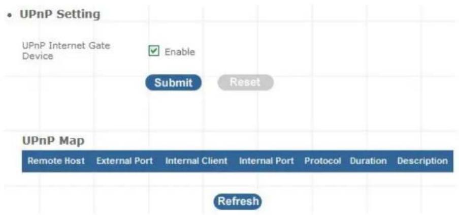
UPnP provides support for communication between control points and devices. The network media, the TCP/IP protocol suite and HTTP provide basic network connectivity and addressing needed. On top of these open, standard, Internet based protocols, UPnP defines a set of HTTP servers to handle discovery, description, control, events, and presentation.
flowchart
graph TD
    A["UPnP Internet Gate Device"] --> B["Enable"]
    B --> C["Submit"]
    C --> D["Reset"]
    E["UPnP Map"] --> F["Remote Host"]
    E --> G["External Port"]
    E --> H["Internal Client"]
    E --> I["Internal Port"]
    E --> J["Protocol"]
    E --> K["Duration"]
    E --> L["Description"]
    M["Refresh"] --> N
Figure 4-32. UPnP settings
UPNP Internet Gate Enable/Disable UPNP Service to working, default Device setting is Disable.
Table 4-18. UPnP description
Call Out Block List
The DDNS (Dynamic DNS) service allows you to alias a dynamic IP address to a static hostname, allowing your computer to be more easily accessed from various locations on the Internet. Without
DDNS, the users should use the WAN IP to reach internal server. It is inconvenient for the users if this IP is dynamic. With DDNS supported, you apply a DNS name (e.g., www.IPPBX.com) for your server (e.g., Web server) from a DDNS server. The outside users can always access the web server using the www.IP-PBX.com regardless of the WAN IP.
When you want your internal server to be accessed by using DNS name rather than using the dynamic IP address, you can use the DDNS service. The DDNS server allows to alias a dynamic IP address to a static hostname.
Unlike DNS that only works with static IP addresses, DDNS works with dynamic IP addresses, such as those assigned by an ISP or other DHCP server. DDNS is popular with home networkers, who typically receive dynamic, frequently-changing IP addresses from their service provider.
DDNS is a method of keeping a domain name linked to a changing (dynamic) IP address. With most Cable and DSL connections, you are assigned a dynamic IP address and that address is used only for the duration of that specific connection. With the IP-PBX, you can setup your DDNS service and the IP-PBX will automatically update your DDNS server every time it receives a different IP address.
Network Settings
- DDNS Setting
DDNS
DDNS Server Type
DDNS Username
DDNS Password
Confirmed Password
Hostname to register
DDNS Interval Registration

Enable






Enable
Submit
Reset
Figure 4-33. DDNS settings
| Enable | Enable/Disable the DDNS service, default setting is Disable. |
| DDNS Server Type | The IP-PBX support two types of DDNS, DynDns.org or No-IP.com |
| DDNS Username | The username which you register in DynDns.org or No-IP.com website. |
| DDNS Password | The password which you register in DynDns.org or No-IP.com website. |
| Confirmed Password | Confirm the password which you typing. |
| Hostname to register | The hostname which you register in DynDns.org or No-IP.com |
Table 4-19. DDNS description
SNTP
The simple network management protocol (SNMP) forms part of the internet protocol suite as defined by the Internet Engineering Task Force (IETF). SNMP is used by network management systems to monitor network-attached devices for conditions that warrant administrative attention. It consists of a set of standards for network management, including an Application Layer protocol, a dIP-PBXbase schema, and a set of dIP-PBX objects.
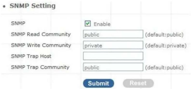
Figure 4-34. SNMP settings
| Enable | Enable/Disable the SNMP service, default setting is Disable. (Support SNMP version 1 or SNMP version 2c). |
| SNMP Read Community | SNMP Read Community string so that EPICenter can retrieve information.(default :public) |
| SNMP Write Community | Specifies the name of the SNMP write community to which the printer device that this actual destination represents belongs.(Default:private) |
| SNMP Trap Host | Defines an SNMP trap host to which AppCelera will send trap messages. (Default address is empty) |
| SNMP Trap Community | The SNMP trap community name. The community name functions as a password for sending trap notifications to the target SNMP manager. (Default: public). |
Table 4-20. SNMP description
Admin Account
The administrator account can access the management interface through the web browser.
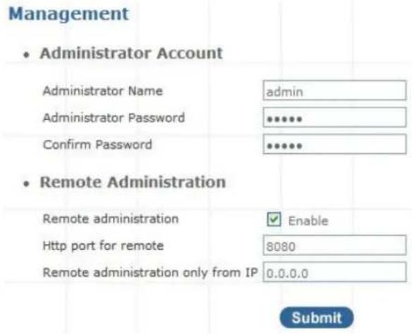
Figure 5-1. Management settings
| Administrator Name | Assign a name to represent the administrator account. Maximum 16 characters. Legal characters can be the upper letter “A” to “Z”, lower letter “a” to “z”, digit number “0” to “9” and an underscore sign; ”_”. |
| Administrator Password | Assign an administrator password. Maximum 16 characters and minimum 6 characters with mix of digits and letters characters. Legal characters can be the upper letter “A” to “Z”, lower letter “a” to “z”, digit number “0” to “9” and an underscore sign”. |
| Confirm Password | Enter the administrator password again. Remote Administrator allows the device to be configured through the WAN port from the Internet using a web browser. A username and password is still required to access the browser-based management interface. |
| Remote Administration | Enable/Disable to access from remote site. Default setting is “Disable”. |
| Http port for remote | If you allowed the access from the remote site, assign the http port used to access the IP-PBX. Default port number is “8080”. |
| Remote administration only from IP | Internet IP address of the computer that has access to the IP-PBX.Assign the legal IP address.Example: http://x.x.x.x:8080 where as x.x.x.x is the WAN IP address and 8080 is the port used for the Web-Management interface. |
Table 5-1. Management description

Note
- The administrator name and password are case-sensitive and the "blank" character is an illegal character
- Only the administrator account has the ability to change account password.
Date & Time
▶ Manual Time Setting
Management
- Date/Time
Date Time Set By
Time Zone
Daylight Saving
Date Value Setting
Time Value Setting

Manual Time Setting © NTP Time Server
(GMT+08:00) Beijing, Singapore, Taipei

Year: 2007 Month: 08 Day: 16
Hour: 17 Minute: 27 Second: 27
Submit
Figure 5-2. Date/Time-Manual time settings
Manual Time Setting
Set up the time manually.
Table 5-2. Date/Time-Manual time description
NTP Time Server
Management
- Date/Time
Date Time Set By
Time Zone
Daylight Saving
NTP Update Interval
NTP Server 1
NTP Server 2

Manual Time Setting Ⓞ NTP Time Server
(GMT+08:00) Beijing, Singapore, Taipei

24 hours (1..1000, default:24)
pool.ntp.org
[Non-Text]
Submit
Figure 5-3. Date/Time-NTP time settings
| NTP Time Server | Protocol used to help match your system clock with an accurate time source. For example atomic clock or a server. |
| Time Zone | Choose your time zone, Default is (GMT+8:00) Beijing, Singapore, Taipei. |
| Daylight Saving | Enable / Disable. Default is Disabling, time during which clocks are set one hour ahead of local standard time; widely adopted during summer to provide extra daylight in the evenings. |
| NTP Update Interval | Default is 24 hours; This is used to select the frequency of. NTP updates. |
| NTP Server 1 | Default is “pool.ntp.org”, NTP Server address. |
| NTP Server 2 | Default is empty. |
Table 5-3. Date/Time-NTP time description
Ping Test
This useful diagnostic utility can be used to check if a computer is on the Internet. It sends ping packets and listens for replies from the specific host. Enter in a host name or the IP address that you want to ping (Packet Internet Groper) and click Ping. Example: www.yahoo.com or 209.131.36.158
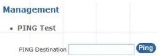
Figure 5-4. Ping test settings
Ping Destination
Assign a legal IP address.
Table 5-4. Ping test description
Save & Restore
All settings can be saving to a local file. Pervious device configuration can also be restored by upload a local file back to the device.
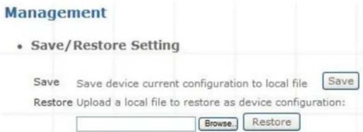
Figure 5-5. Save/Restore settings
Factory Default
This function is used to restore all the parameters back to factory default setting. You can use the Save/Restore Setting to check the factory default configuration, after you click on the Set button.
Management
• Factory Default Setting
Set device configuration to Factory default setting:
Submit
Figure 5-6. Factory default settings
Admin Account
You can upgrade the firmware of the device using this tool. Make sure that the firmware you want to use is saved on the local hard drive of your computer. Click on Browse to search the local hard drive for the firmware to be used for the update. Upgrading the firmware will not change any of your system settings but it is recommended that you save your system settings before doing a firmware upgrade.
Firmware Update
Firmware File

Upload
Figure 5-7. Firmware update settings
Firmware Name
Select that you want to upgrade Firmware version.
Table 5-5. Firmware update description
System Information
System Information page indicates the current setup-status of the device, it includes LAN, WAN, (Status and MAC Address), Host Name / System Date time / Machines Life time and system firmware information. The information and options on this page will vary according to your WAN setting (Static IP, DHCP, or PPPoE).
-If your WAN connection is set up for Dynamic IP address, the page will display "Release" and "Renew" buttons. Use "Release" to disconnect from your ISP and use "Renew" to connect to your ISP.
-If your WAN connection is set up for PPPoE, the page will display "Connect" and "Disconnect" buttons. Use "Disconnect" to drop the PPPoE connection and use "Connect" to establish the PPPoE connection
System Information
- System
| Firmware Version | IPPBX 0.0.10 |
| Host Name | SIP.IPPBX |
| Date & Time | Mon Feb 25 11:48:27 CST 2008 |
| Life Time | 1 hour(s)20 min(s)42 sec(s) |
| Mode | NAT |
• WAN
| WAN Type | Static IP |
| IP Address | 172.16.0.1 |
| Subnet Mask | 255.255.0.0 |
| Default Gateway | 172.16.0.254 |
| MTU | 1500 |
| DNS 1 (Primary) | 168.95.1.1 |
| DNS 2 (Secondary) | 168.95.192.1 |
• LAN
| IP Address | 192.168.0.1 |
| Subnet Mask | 255.255.255.0 |
| DHCP Server Function | Enabled |
- Physical MAC
| WAN | 00:30:4F:50:00:06 |
| LAN | 00:30:4F:50:00:07 |
Figure 6-1. System Information
PBX Extension Status
This page displays the information of Extension/Users Registration status.
- Extension Status

Figure 6-2. Extension Status

Register OK
SIP device is connected to IPPBX

Talk on the telephone
The connection from/to the other end of SIP device is established.

Register Unknown
Sip device is not connected to IPPBX
Table 6-1. Extension Status description
PBX Trunk Status
This page displays the information of Service Provider Registration status.
• Service Provider Status

Figure 6-3. Service Provider Status

Register OK
SIP Trunk is registered

Register Unknown
SIP Trunk is not registered
Table 6-2. Service Provider Status description
Call Detail Record
Call Detail Record (CDR) contains the call history of the extensions when calls was made or received.
Recorded information include: Source Number, Destination Number, Start Time, Answer Time, End Time, Duration Time and Status.
- Call Detail Record
<< [1] >>
| Source No | Destination No | Start Time | Answer Time | End Time | Duration Time | Status |
| 200 | 100 | 2007-11-2814:23:51 | 2007-11-2814:23:51 | 2007-11-2814:24:16 | 25 | ANSWERED |
| 100 | out | 2007-11-2814:24:41 | 2007-11-2814:24:42 | 2007-11-2814:24:47 | 6 | ANSWERED |
| 2010 | s | 2007-11-2814:24:42 | 2007-11-2814:24:42 | 2007-11-2814:24:47 | 5 | ANSWERED |
| 100 | out | 2007-11-2814:24:52 | 2007-11-2814:24:57 | 2007-11-2814:24:58 | 6 | ANSWERED |
| 431 | 100 | 2007-11-2814:29:06 | 2007-11-2814:29:07 | 2007-11-2814:29:11 | 5 | ANSWERED |
| 431 | 100 | 2007-11-2814:30:12 | 2007-11-2814:30:14 | 2007-11-2814:30:26 | 14 | ANSWERED |
Figure 6-4. Call Detail Record
Press << to go to the Next page; Press >> to go to the Previous page
| Source No | Caller's ID |
| Destination No | ID of destination extension / user |
| Start Time | The date/time when the call initiated |
| Answer Time | The date/time when the call answered |
| End Time | The date/time when the call terminated |
| Duration Time | Duration of the call, in seconds, from Start Time to End Time. |
| Status | 4 status available (1) Answered; (2) No Answer; (3) Busy; (4) Failed. |
Table 6-3. Call Detail Record description
Note
- IPPBX / WIPPBX have save Maximum 500 Records to the memory. If you press Reset bottom or reboot the system, the record will be erased.
How to use Call Parking function
The followings are the Call Park function settings, and all of VoIP devices (ATA, GW and IP Phone) were registered with Wi-Fi IP PBX.
Extension to Dial for Parking Calls: 700
➢ Extensions to park calls on :701-720
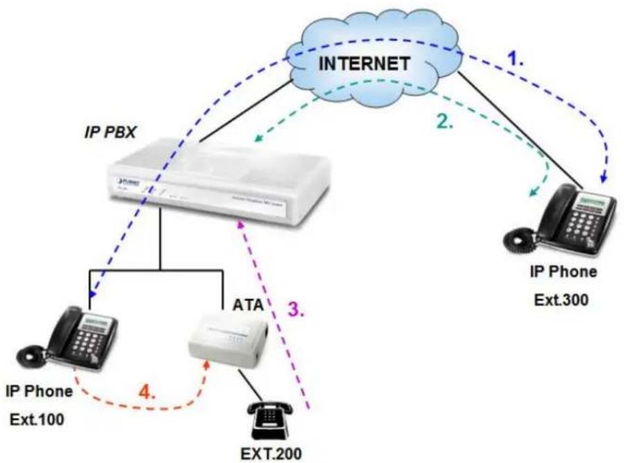
flowchart
graph TD
    A["IP PBX"] -->|1.| B["INTERNET"]
    A -->|2.| C["IP Phone Ext.300"]
    A -->|3.| D["ATA"]
    D -->|4.| E["IP Phone Ext.100"]
    D --> F["EXT.200"]
    B -->|1.| B
    C -->|2.| C
    D -->|3.| D
Figure A-1. Call Parking sample scenario
- Ext.100 and Ext.300 are talking.
- Ext.300 press Transfer button and dial "700#" to carry out the Call Parking function, and the voice guide will tell Ext.300 a retrieve number (ex:701) to set parking call (At this moment, the remote extension will hear the holding music.)
- Ext.200 dial retrieve number (ex:701) to pick up call.
- Ext.100 are talking with Ext.200
How to use Call Pick-up function
The followings are the Call Pickup function settings, and all of VoIP devices (ATA, GW and IP Phone) were registered with IP PBX.
➢ Pickup Extension: *8
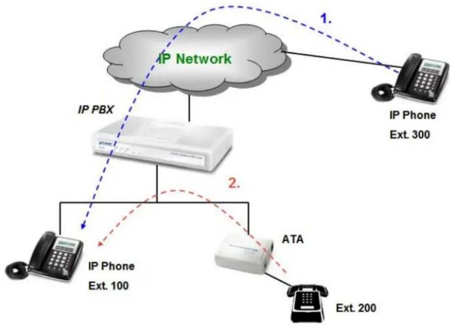
flowchart
graph TD
    A["IP Network"] -->|1.| B["IP Phone Ext. 300"]
    A -->|2.| C["ATA Ext. 200"]
    A --> D["IP PBX"]
    D --> E["IP Phone Ext. 100"]
Figure B-1. Call Pickup sample scenario
- Ext.300 call to Ext.100, and Ext.100 is ringing.
- Ext.200 dial "*8#" to pickup the call for Ext.100, and Ext.200 is talking with Ext.300.
Appendix C
How to record Sound and replacement Sounds package
This sample for how to record sound as gsm format file for IP PBX use, and to replacement the Sounds package.
What do you need?
- Original Sound file in English version: sounds.tar.gz (*)
- IVR menu Script: IVR script.txt (*)
- A Software can record the sound file, such as Wavepad Editor (http://www.nch.com.au)
- A Software can compress the folders into tar file, such as IZarc (http://lzarc.org)
(*): Please contact with our VoIP Technical Support Team (support voip@planet.com.tw) for getting the related IVR files.
Step1: Uncompress the sound file (sounds.tar.gz), and you will see the file architecture and what voice files included.
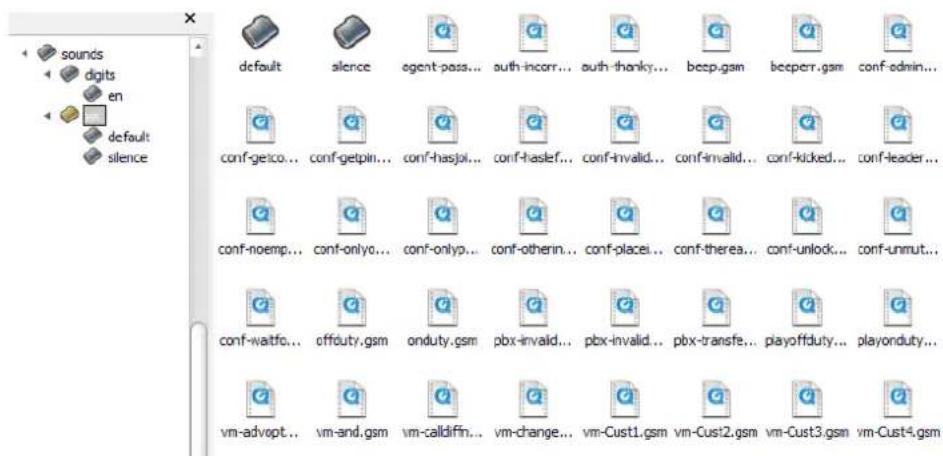
Step2: Find the script, and translate it to your language, first record the sound with Wavepad Editor Software.
Example: Thank you (English) ---→ Merci (French)
How to Record IVR?
This sample is for how to record sound, as gsm format file for IP PBX series use.
- Visit to www.nch.com.sound home-page, to download Wavepad v3.05 (for windows) sound tools install your pc.
- In this screen, create a new file, Input 8000Hz and select mono (Single) channel then press ok to finish.
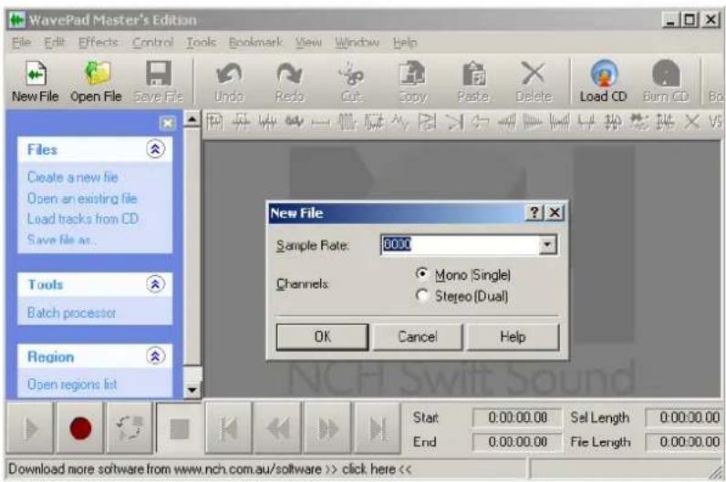
- Press F5 Select your recording sound device and record channel or recording volume level.
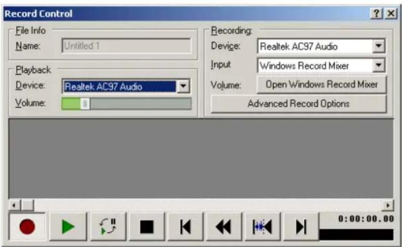
- Press

Start recording
- Save the current file as WAV or gsm format to finish.
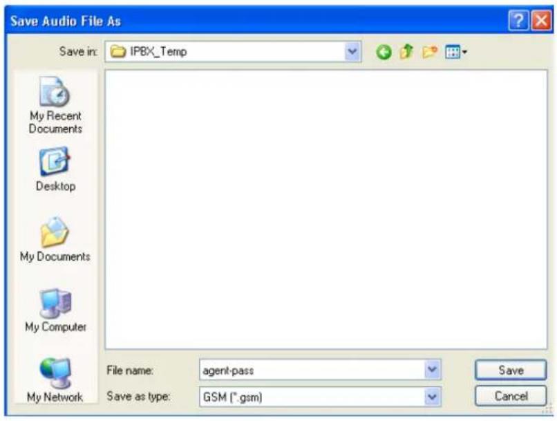
Step3: Replace the original file, and please don't change the file name.
Step4: Compress the sounds folder to a zipped file with using izarc, and please reverence the following for the steps.
- After installed Izarc.

sounds.tar IZArc GZ Archive 1, 120 KB
- Right Click and then select "Add to Archive File...".
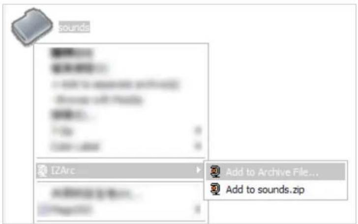
- Select "TAR (.tar)" for the Archiving Type, and "Tar" for the Method, and then click "Add" to create the compress file.
Note: Please don't change the file location of the sounds folder.
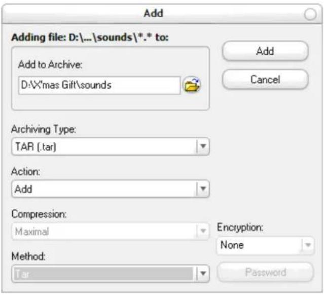
Step5: Please login the Web UI of IP PBX, and select Voice Management -> Upload Voice File, and then click the "Browse" button to allocate the "sounds.tar" on your PC. Once the file is selected, please click "Upload" to start the upgrade process. Once the upgrade is complete you can start using your devices.
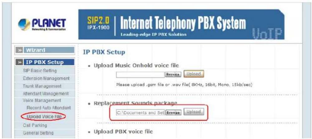
Record Voice Guide Process
IPX-300W provides Record Voice Menu by Phone function. Please register your VoIP devices to Wi-Fi IP PBX at first, and then check the Record voice code from "IP PBX Setup -> record Voice Menu" page.
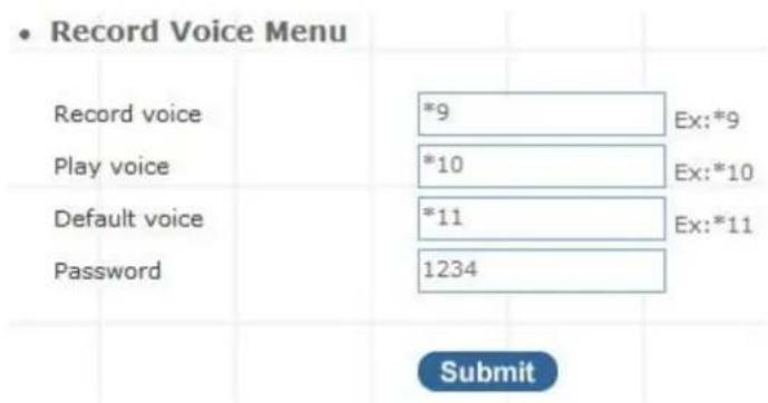
Figure C-1. Record voice menu settings
VoIP devices dial *9 to entry the Record Voice Menu, then refer to the following record processes to record the Voice Menu.
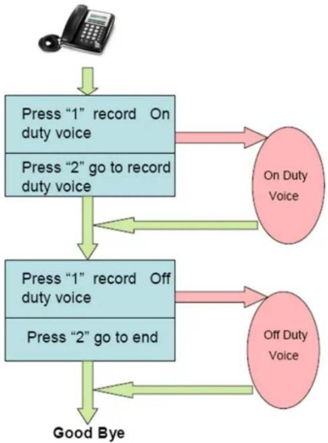
flowchart
graph TD
    A["Telephone"] --> B["Press "1" record On duty voice"]
    B --> C["On Duty Voice"]
    B --> D["Press "2" go to record duty voice"]
    D --> E["Press "1" record Off duty voice"]
    E --> F["On Duty Voice"]
    E --> G["Press "2" go to end"]
    G --> H["Good Bye"]
Figure C-2. Voice record processes
Appendix E
Voice Communication Samples
The chapter shows you the concept and command to help you configure your IP PBX System through sample configuration. And provide several ways to make calls to desired destination in IP PBX. In this section, we'll lead you step by step to establish your first voice communication via web browsers operations.
IP Phone and Wi-Fi Phone register to IPX-300W
In the following samples, we'll introduce IP Phone and Wi-Fi Phone register to IP PBX applications.
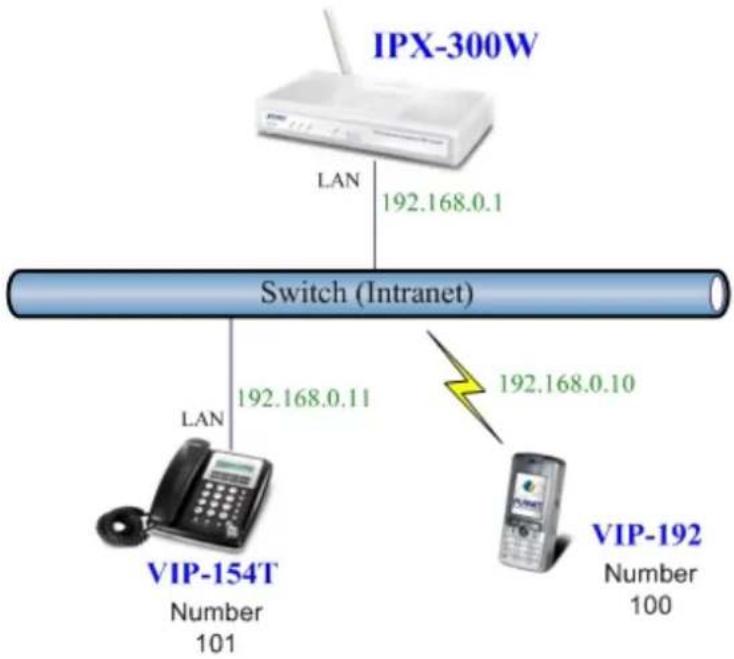
flowchart
graph TD
    A["IPX-300W"] -->|LAN 192.168.0.1| B["Switch (Intranet)"]
    B -->|LAN 192.168.0.11| C["VIP-154T Number 101"]
    B -->|192.168.0.10| D["VIP-192 Number 100"]
Figure D-1. Topology of instruction example
Machine Configuration:
STEP 1:
Please log in IP PBX via web browser and browse to "Network Setup -> WLAN Setting" configuration menu. Enable the WLAN and setup the related configuration. The sample configuration screen is shown below:
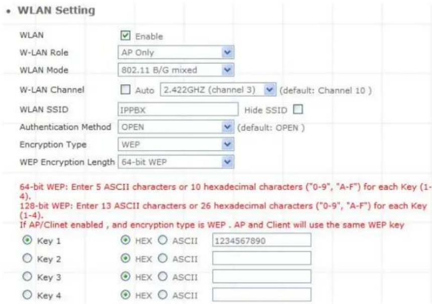
Figure D-2. WLAN Setting of IPX-300W
STEP 2:
Browse to "IP PBX Setup → User Extensions Setup" configuration menu.
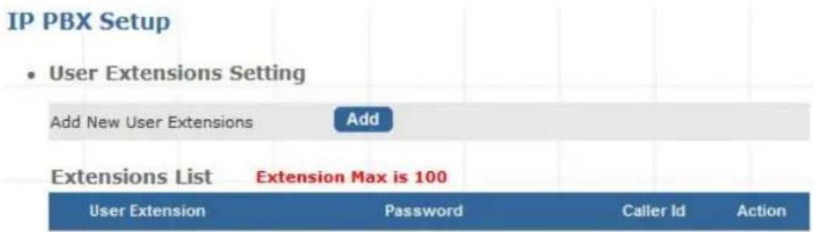
Figure D-3. User extension setting of IP PBX
STEP 3:
Click the "Add" button to create extension account ext.100 and ext.101.
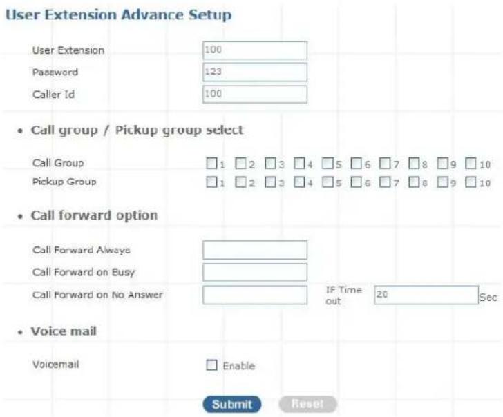
Figure D-4. Add extension setting of IP PBX
STEP 4:
Please log in VIP-154T and browser to "SIP setting → Domain Service" configuration menu. Insert the account/password information then save and reboot machine. The sample configuration screen is shown below:
Service Domain Settings
You could set information of service domains in this page.
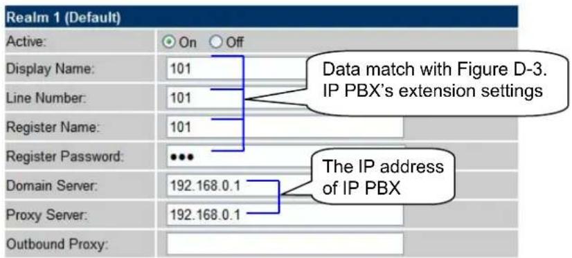
Figure D-5. Web page of VIP-154T
STEP 5:
Please take VIP-192 and setup the wireless network to connect with IP PBX (IPX-300W) by keypad menu method. Then log in VIP-192 via web browser and browser to "SIP Settings" configuration menu. Insert the Register and Outbound Proxy IP Address information.
![SIP Phone Setting SIP Phone Port Number 5060 [1024 - 65535] Registrar Server Registrar Server Domain Name/IP Address 192.168.0.1 Registrar Server Port Number 5060 [1024 - 65535] Authentication Expire Time 3600 sec. (Default: 3600 sec.)[60 - 9999] Outbound Proxy Server Outbound Proxy Domain Name/IP Address 192.168.0.1 Outbound Proxy Port Number 5060 [1024 - 65535]](/content/2026/05/788719/images/6f40d91d799a2180ab91646efd6480dad35f020fa6093946d87f82ff05f023f0.jpg)
Figure D-6. SIP settings of VIP-192
Then browse to "SIP Account Settings" configuration menu and fill in the account/password information. The sample configuration screen is shown below:
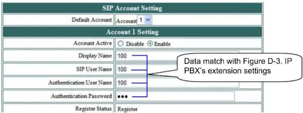
Figure D-7. SIP account settings of VIP-192
STEP 6:
After both of devices have registered to IP PBX successfully, it could browse to "Information -> PBX Extension Status" page to show the registration status:
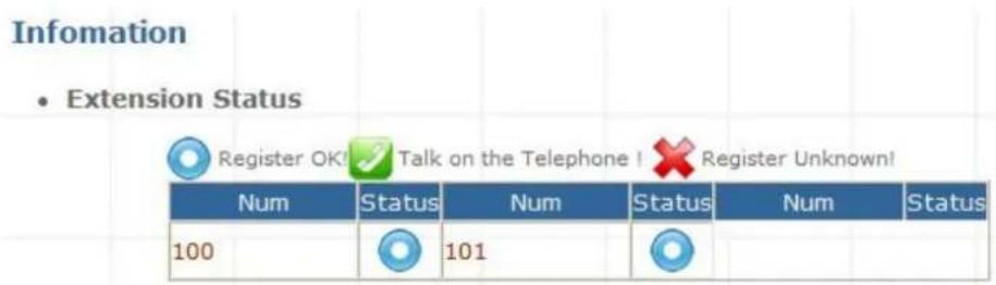
Figure D-8. Extension status
Test the Scenario:
- VIP-154T pick up the telephone
- Dial the number: 100 (VIP-192) shall be able to connect to the VIP-192
- Then the VIP-192 should ring. Please repeat the same dialing steps on VIP-192 to establish the first voice communication from VIP-154T
IP Phone and Wi-Fi Phone make off-Net calls via Gateway
In the following samples, we'll introduce VIP-154T and VIP-192 makes off-Net Calls (PSTN calls) via VIP-480FO applications.
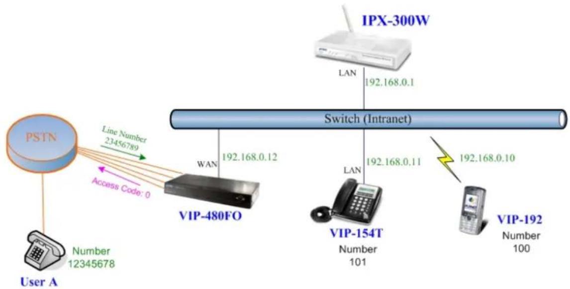
flowchart
graph TD
    PSTN[" PSTN "] -->|Line Number 23456789| VIP-480FO["VIP-480FO"]
    PSTN -->|Access Code: 0| VIP-480FO
    VIP-480FO -->|LAN 192.168.0.12| Switch["Switch (Intranet)"]
    Switch -->|LAN 192.168.0.11| VIP-154T["VIP-154T"]
    VIP-154T -->|LAN 192.168.0.10| VIP-192["VIP-192"]
    VIP-154T -->|Number 101| Switch
    VIP-192 -->|Number 100| Switch
    IPX-300W["IPX-300W"] -->|LAN 192.168.0.1| Switch
Figure D-9. Installation example with VIP-480FO
Machine Configuration:
STEP 1:
Please refer to the first sample and let VIP-154T and VIP-192 register to IP PBX.
STEP 2:
Please log in IP PBX via web browser and browse to "IP PBX Setup → User Extensions Setup" configuration menu to add four accounts for VIP-480FO using.
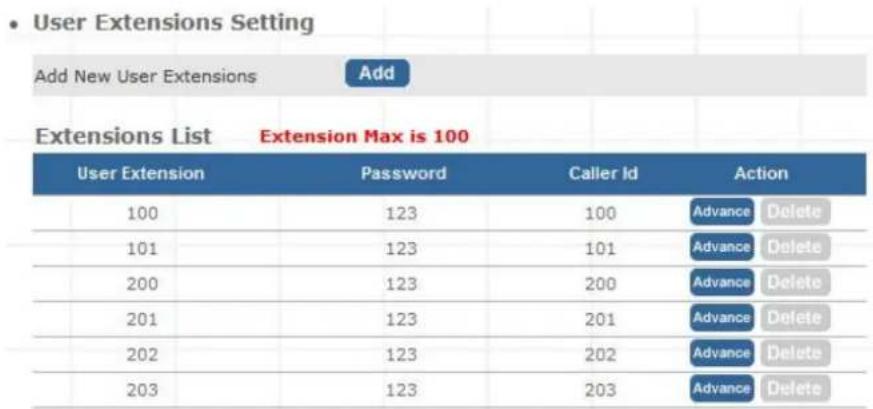
Figure D-10. Add accounts for VIP-480FO
STEP 3:
Browse to "IP PBX Setup → Attendant Extension" configuration menu. Assign an attendant number which inexistence extension in Extension List and the sample configuration screen is shown below:
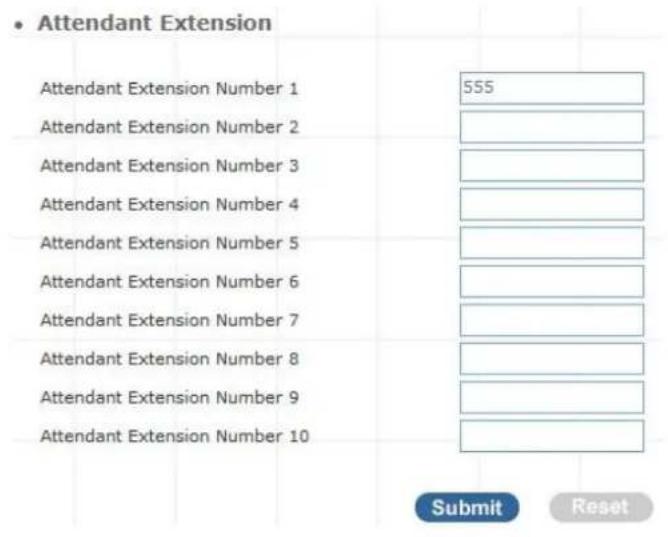
Figure D-11. Assign an attendant number
Pressing the "Submit" button for activate the configuration.
STEP 4:
Browse to "IP PBX Setup → Trunk Management → Gateway Trunk" configuration menu. Fill in the IP address of VIP-480FO for connecting with VIP-480FO by peer-to-peer mode, and press the "Insert" button for activate the configuration.

Figure D-12. Add an Gateway trunk for connecting with VIP-480FO
STEP 5:
Browse to "IP PBX Setup → Trunk Management → Trunk Group" configuration menu. Add a Trunk Group for making off-Net calls via VIP-480FO.
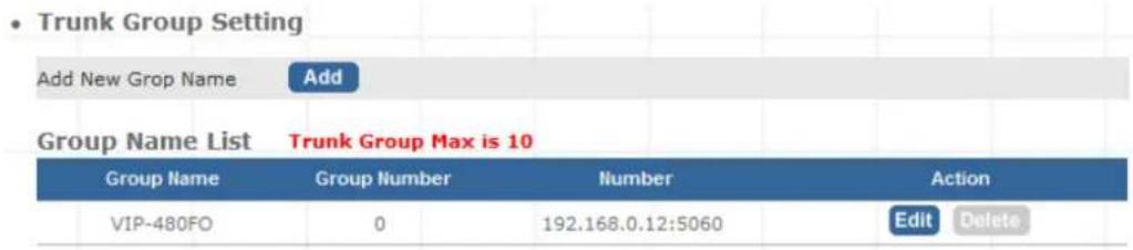
Figure D-13. Add Trunk Group number for grabbing the FXO ports of VIP-480FO
STEP 6:
Please log in VIP-480FO via web browser and browse to "Advance Setup → VoIP Setup → VoIP Basic" configuration menu. Insert the account/password information and set up the hunting function. The sample configuration screen is shown below:
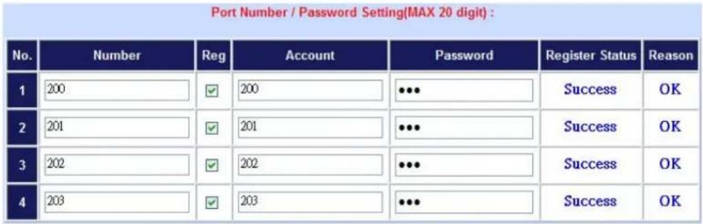
Figure D-14. Set up the number of FXO ports of VIP-480FO
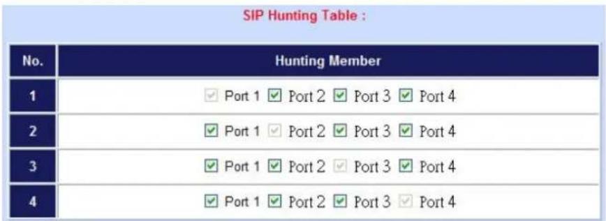
Figure D-15. Set up the Hunting Member of FXO ports
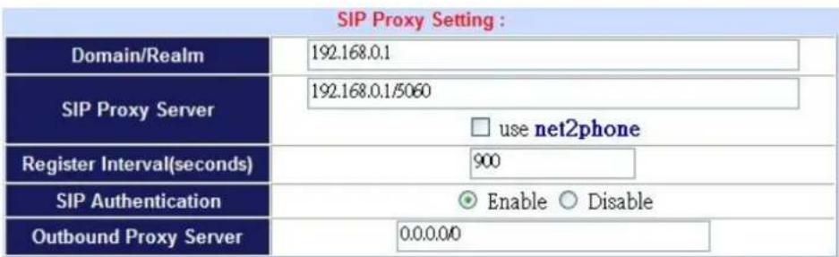
Figure D-16. Set up the Proxy Server IP address for register to IPX-300W
STEP 7:
Browse to "Dialing Plan" configuration menu. Add an Incoming Dial Plan (no.1x) for redirect the PSTN outgoing calls to FXO ports.
Incoming Dial Plan: (maximum 50 entries, maximum length of prefix digits is 16 digit, maximum length of number is 20 digit):
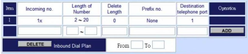
Figure D-17. Add an incoming dial plan
STEP 8:
Browse to "Port Status" configuration menu. Fill in the auto attendant number 555 to all of ports. (Where 555 is the auto-attendant number of IP PBX)
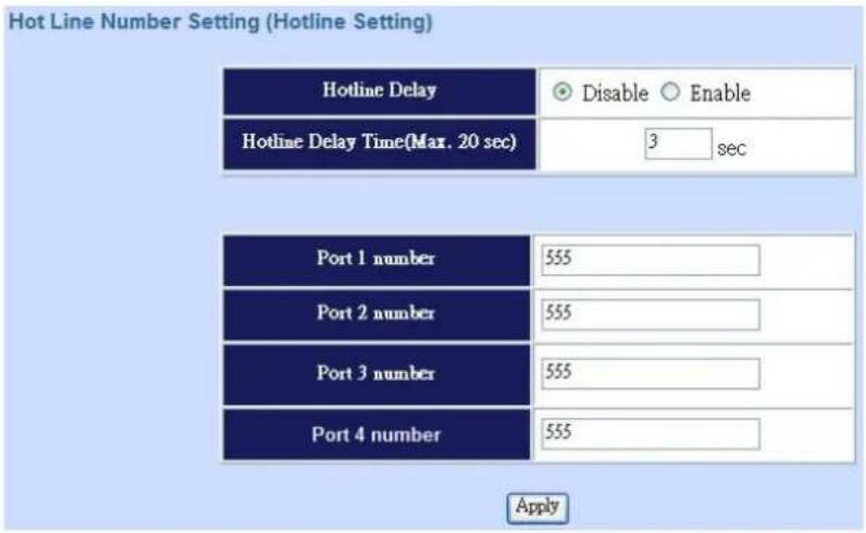
Figure D-18. Hot Line to auto-attendant of IPX-300W
STEP 8:
After all of devices have registered to IP PBX successfully, the Extension Status page will show the registration status:
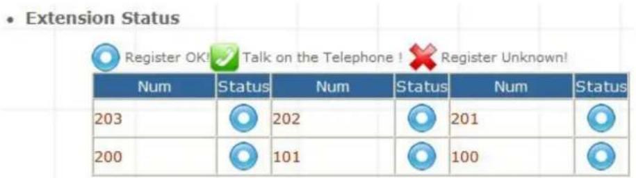
Figure D-19. Extension status page with Phone and Gateway registered
Test the Scenario:
- VIP-154T pick up the telephone
- Dial the number: 0 will hear the dial tone, and dial the number: 12345678. This call will hunt the FXO port of VIP-480FO and shall be able connect to the User A.
- Then the telephone of User A will ringing, User A can pick up the handset and talk with VIP-154T.
- Both VIP-154T and User A hang up the calls.
- User A pick up the telephone and dial the number: 23456789 should be able to connect to the Auto Attendant System of IP PBX.
- The User A will hear the prompts, and dial the extension number: 100 shall be able connect to the VIP-192.
- Then the VIP-192 should ringing, and it to pick up the call then talk with User A.
IP Phone and Wi-Fi Phone make external SIP Proxy calls via SIP Trunk
In the following samples, we'll introduce VIP-154T and VIP-192 makes SIP Proxy calls via SIP Trunk applications.
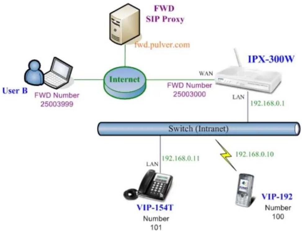
flowchart
graph TD
    A["User B"] -->|FWD Number 25003999| B["Internet"]
    B -->|FWD Number 25003000| C["IPX-300W"]
    C -->|LAN 192.168.0.1| D["Switch (Intranet)"]
    D -->|LAN 192.168.0.11| E["VIP-154T"]
    E -->|LAN 192.168.0.10| F["VIP-192"]
    F -->|LAN 192.168.0.10| G["VIP-192"]
    C -->|FWD Sulver.com| H["FWD SIP Proxy"]
Figure D-20. Installation example with VIP-480FO
Machine Configuration:
STEP 1:
Please refer to the first sample and let VIP-154T and VIP-192 register to IP PBX.
STEP 2:
Browse to "IP PBX Setup → Trunk Management → SIP Trunk" configuration menu. Add a new Service Provider account for registering to FWD SIP Proxy.
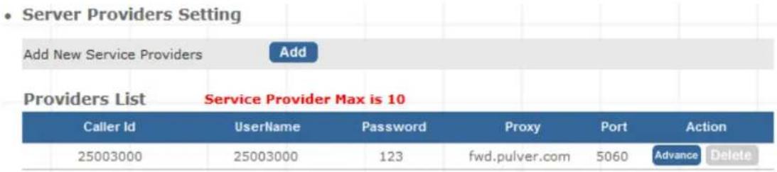
Figure D-21. Add a Service Provider account
STEP 3:
Browse to "IP PBX Setup → Trunk Management → Trunk Group" configuration menu. Add a Trunk Group for making external SIP Proxy calls.
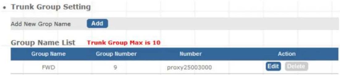
Figure D-22. Add Trunk Group number
STEP 4:
After the SIP Trunk has registered to FWD SIP Proxy successfully, the Service Provider Status page will show the registration status:
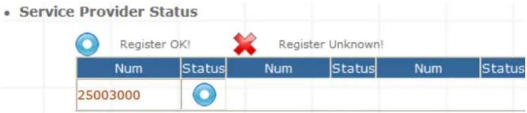
Figure D-23. Service Provider status page
Test the Scenario:
- VIP-154T pick up the telephone
- Dial the number: 9 will hear the dial tone, and dial the number: 25003999. This call shall be able connect to the User B.
- Then the softphone of User B will ringing, User B can answer the call and talk with VIP-154T.
- Both VIP-154T and User B hang up the calls.
- User B pick up and dial the number: 25003000 should be able to connect to the Auto Attendant System of IP PBX.
- The User B will hear the prompts, and dial the extension number: 100 shall be able connect to the VIP-192.
- Then the VIP-192 should ringing, and it to pick up the call then talk with User B.
Appendix F
IPX-300 Series Specifications
| Product | Internet Telephony PBX System | Wi-Fi Internet Telephony PBX System |
| Model | IPX-300 | IPX-300W |
| Hardware | ||
| WLAN Standards | - IEEE 802.11 b/g | |
| Wireless Frequency Range | - 2.4GHz ~ 2.4835 GHz | |
| Security | - | 64/128 bit WEP data encryption, WPA, WPA-PSK, WPA2, WPA2-PSK, WPA / WPA2 mix mode, WPAPSK / WPA2PSK mix mode |
| Operating Frequencies / Channel | - | USA / Canada: 2.412 GHz - 2.426 GHz (11 channels)Europe: 2.412 GHz - 2.472 GHz (13 channels)Japan: 2.412 GHz - 2.477 GHz (14 channels) |
| Data Rate | - | 802.11b: CCK (11Mbps,5.5Mbps), DQPSK (2Mbps), DBPSK (1Mbps)802.11g: OFDM (54Mbps, 48Mbps, 36Mbps, 24Mbps, 18Mbps, 12Mbps, 9Mbps, 6Mbps) |
| Wireless Signal Range* | - | Indoors: Up to 230 ft (70 meters)Outdoors: Up to 1050 ft (320 meters) |
| LAN 1 RJ-45 (10/100Base-TX, Auto-Sensing/Switching) | |
| WAN | 1 RJ-45 (10/100Base-TX, Auto-Sensing/Switch |
| Standards and Protocol | |
| Call control | SIP 2.0 (RFC3261), SDP (RFC 2327), Symmetric RTP |
| Registration | Max. 100 nodes / SIP IP phones/ ATA / FXO gateways |
| Calls | Max. 30 concurrent calls |
| Voice CODEC Support | G.723, G.726, G.729, G.711, GSM, iLBC |
| Voice Processing | DTMF detection and generationIn-Band and Out-of-Band (RFC 2833), (SIP INFO)Supports password authentication using MD5 digest |
| PBX features | Auto Attendant (AA)Interactive Voice Response (IVR)Records IVR via IP PhoneVoicemail Support (VM)Voicemail Send to E-mailCall Detailed Record (CDR)User Management via Web BrowsersWeb Firmware Upgrade |
| Backup and Restore Configuration fileCall/Pickup GroupDisplays 100 Registered User's Status: Unregistered / Registered / On-CallDisplays 20 Registered Trunk's Status: Unregistered / RegisteredFax Support using G.711 Pass-Through or T.38** | ||
| Call features | Caller IDCall GroupCall HoldCall WaitingCall TransferCall Forward (Always, Busy, No Answer)Call PickupCall ParkCall ResumeMusic on HoldThree-way conference with feature phones (VIP-154T series, VIP-155PT/350PT/ 550PT and ATA series: VIP-156/ 157/ 158 / 161W) | |
| Internet Sharing | ||
| Protocol TCP/IP, UDP/RTP/RTCP, HTTP, ICMP, ARP, NAT, DHCP, PPPoE, DNS | ||
| Advanced Function | NAT/Bridge mode, DHCP server, Static Route, DMZ, Virtual Server, Port Trigger, Packet / URL Filter, UPnP, DDNS, SNMP, Ping test | |
| Network and Configuration | ||
| Connection Type | Static IP, PPPoE, DHCP | |
| Management | HTTP Web Browser | |
| LED Indications | System: 1, PWRWAN: 1, LNK/ACTLAN: 1, LNK/ACT | System: 1, PWRWAN: 1, LNK/ACTLAN: 1, LNK/ACTWLAN: 1, LNK/ACT |
| Environment | ||
| Dimension (W x D x H) | 180 x 110 x 25 mm | |
| Operating Temperature | 0~40 degree C, 0~90% humidity | |
| Power Requirement | 12V DC | |
| EMC/EMI | CE, FCC Class B | |
| Remark | * Signal Range depends on the used antenna**T.38 support is dependent on fax machine, SIP provider and network / transport resilience | |
IP PBX Voice Sounds
- PBX-files
agent-pass.WAV: Please enter your password followed by the pound key.
auth-incorrect.WAV: Password incorrect. Please enter your password followed by the pound key.
auth-thankyou.WAV: Thank you
beep.WAV: "beep tone"
beeperr.WAV: "beep tone"
offduty.WAV: Now is off hour, if you know the extension of the party "you" wish to reach, dial now, or call again tomorrow
onduty.WAV: Thank you for calling, if you the extension of the party "you" wish to reach dial now, or dial 9 for operator.
pbx-invalid.WAV: I am sorry, that's not a valid extension. Please try again
pbx-invalidpark.WAV: I am sorry, there is no call parked on that extension. Please try again.
playoffduty.WAV: Now play off duty prompt voice
playonduty.WAV: Now play on duty prompt voice
recordoffduty.WAV: To record off duty prompt voice, please press 1 after the beep sound start recording, to finishing recording please press pound key, press 2 to exit the system
recordonduty.WAV: To record on duty prompt voice, please press 1 after the beep sound start recording, to finishing recording please press pound key, press 2 to exit the system
thank-you-for-calling.WAV: thank you for calling
conf-adminmenu: Please press 1 to mute or unmute yourself, 2 to lock or unlock the conference, 3 to eject the last user, 4 or 6 to decrease or increase the conference volume, 7 or 9 to decrease or increase your volume, or 8 to exit
conf-enteringno: You are entering conference number
conf-errormenu: Invalid Choice
conf-getchannel: Please enter the channel number followed by the pound key.
conf-getconfno: Please enter your conference number followed by the pound key.
conf-getpin: Please enter the conference pin number.
conf-hasjoin: is now in the conference.
conf-hasleft: has left the conference.
conf-invalid: That is not a valid conference number. Please try again.
conf-invalidpin: That pin is invalid for this conference.
conf-kicked: You have been kicked from this conference
conf-leaderhasleft: The leader has left the conference.
conf-locked: This conference is locked!
conf-lockednow: The conference is now locked
conf-muted: You are now muted
conf-noempty: No empty conferences currently exist.
conf-onlyone: There is currently one other participant in the conference.
conf-onlyperson: You are currently the only person in this conference.
conf-otherinparty: other participants in the conference
conf-placeintoconf: You will now be placed into the conference.
conf-thereare: There are currently
conf-unlockednow: The conference is now unlocked
conf-unmuted: You are now unmuted
conf-usermenu: Please press 1 to mute or unmute yourself, 4 or 6 to decrease or increase the
conference volume, 7 or 9 to decrease or increase your volume, or 8 to exit
conf-userswilljoin: users will join the conference.
conf-userwilljoin: user will join the conference.
conf-waitforleader: The conference will begin when the leader arrives.
Voice-Mail files)
vm-advopts.WAV: press 3 for advanced options
vm-and.WAV: and
vm-calldiffnum.WAV: press 2 to enter a different number
vm-changeto.WAV: Change to which folder?
vm-Cust1.WAV: Folder. Five
vm-Cust2.WAV: Folder. Six
vm-Cust3.WAV: Folder. Seven
vm-Cust4.WAV: Folder. Eight
vm-Cust5.WAV: Folder. Nine
vm-delete.WAV: Press 7 to delete this message.
vm-deleted.WAV: Message deleted.
vm-dialout.WAV: please wait while i connect your call
vm-enter-num-to-call.WAV: please enter the number you wish to call
vm-extension.WAV: extension
vm-Family.WAV: family
vm-first.WAV: first
vm-for.WAV: for
vm-forward.WAV: Press 1 to enter an extension, press 2 to use the directory
vm-forwardoptions.WAV: press 1 to prepend a message or 2 to forward the message without prepending
vm-Friends.WAV: friends
vm-from.WAV: from
vm-from-extension.WAV: message from extension
vm-from-phonenumber.WAV: message from phone number
vm-goodbye.WAV: Goodbye
vm-helpexit.WAV: Press star for help or pound to exit.
vm-INBOX.WAV: new
vm-incorrect-mailbox.WAV: Login incorrect. Mailbox?
vm-instructions.WAV: To look into your messages press 1 now. You may quit voicemail at any time by pressing the pound key.
vm-intro.WAV: Please leave your message after the tone. When done hang up or press the pound key
vm-isonphone.WAV: is on the phone
vm-isunavail.WAV: is unavailable
vm-last.WAV: last
vm-leavemsg.WAV: Press 5 to leave a message
vm-login.WAV: Comedian Mail. Mailbox?
vm-mailboxfull.WAV: sorry but the user's mail box can't accept more messages
vm-message.WAV: message
vm-messages.WAV: messages
vm-minutes.WAV: minutes
vm-mismatch.WAV: The passwords you entered and re-entered did not match. Please try again
vm-msginstruct.WAV: To hear the next message press 6, to repeat this message press 5, to hear the previous message press 4, to delete or undelete this message press zero, to quit voicemail press pound
vm-msgsaved.WAV: Your message has been saved
vm-newpassword.WAV: Please enter your new password followed by the pound key
vm-newuser.WAV: Welcome to Comedian Mail. First, I will guide you through a short setup process
vm-next.WAV: Press 6 to play the next message
vm-no.WAV: no
vm-nobodyavail.WAV: Nobody is available to take your call at the moment
vm-nobox.WAV: you cannot reply to this message because the sender does not have a mailbox
vm-nomore.WAV: No more messages
vm-nonumber.WAV: i'm afraid i don't know who sent this message
vm-num-i-have.WAV: the number i have is
vm-Old.WAV: old
vm-onefor.WAV: Press 1 for
vm-options.WAV: Press 1 to record your unavailable message, press 2 to record your busy message, press 3 to record your name, press 4 to record your temporary greeting, press 5 to change your password, press star to return to the main menu
vm-opts.WAV: Press 2 to change folders, press 3 for advanced options, press zero for mailbox options.
vm-passchanged.WAV: Your passwords have been changed
vm-password.WAV: password
vm-press.WAV: press
vm-prev.WAV: Press 4 for the previous message
vm-reachoper.WAV: press 0 to reach an operator
vm-rec-busy.WAV: After the tone say your busy message and then press the pound key.
vm-received.WAV: received
vm-rec-name.WAV: After the tone say your name and then press the pound key.
vm-rec-temp.WAV: After the tone, say your temporary message, and then press the pound key
vm-rec-unv.WAV: After the tone say your unavailable message and then press the pound key
vm-reenterpassword.WAV: Please re-enter your password followed by the pound key
vm-repeat.WAV: Press 5 to repeat the current message
vm-review.WAV: press 1 to accept this recording press 2 to listen to it press 3 to rerecord your
messagevm-saved.WAV: saved
vm-savedto.WAV: saved to
vm-savefolder.WAV: Which folder should I save the message to?
vm-savemessage.WAV: or 9 to save this message
vm-saveoper.WAV: press 1 to accept this recording, otherwise, please continue to hold
vm-sorry.WAV: I'm sorry I did not understand your response
vm-star-cancel.WAV: press star to cancel
vm-starmain.WAV: press star to return to the main menu
vm-tempgreetactive.WAV: Your temporary greeting is currently active
vm-tempgreeting2.WAV: press 1 to record your temporary greeting, or press 2 to erase your temporary greeting
vm-tempgreeting.WAV: press 1 to record your temporary greeting
vm-tempremoved.WAV: Your temporary greeting has been removed
vm-then-pound.WAV: then press pound
vm-theperson.WAV: The person at extension
vm-tocallback.WAV: press 2 to call the person who sent this message
vm-tocallnum.WAV: press 1 to call this number
vm-tocancel.WAV: or pound to cancel
vm-tocancelmsg.WAV: press star to cancel this message
vm-toenternumber.WAV: press 1 to enter a number
vm-toforward.WAV: Press 8 to forward the message to another user
vm-tohearenv.WAV: press 3 to hear the message envelope
vm-tomakecall.WAV: press 4 to place an outgoing call
vm-tooshort.WAV: your message is too short
vm-toreply.WAV: press 1 to send a reply
vm-torerecord.WAV: press 3 to rerecord your message
vm-undelete.WAV: Press 7 to undelete this message.
vm-undeleted.WAV: Message undeleted
vm-unknown-caller.WAV: from an unknown caller
vm-whichbox.WAV: To leave a message, please enter a mailbox number.
vm-Work.WAV: work
vm-youhave.WAV: you have
- digit-files
a-m.WAV: A.M.
p-m.WAV: P.M.
today.WAV: today
tomorrow.WAV: tomorrow
yesterday.WAV: yesterday
at.WAV: at
oclock.WAV: o'clock
oh.WAV: oh
pound.WAV: pound
star.WAV: star
thousand.WAV: thousand
Number
0.WAV: zero
1.WAV: one
2.WAV: two
3.WAV: three
4.WAV: four
5.WAV: five
6.WAV: six
7.WAV: seven
8.WAV: eight
9.WAV: nine
10.WAV: ten
11.WAV: eleven
12.WAV: twelve
13.WAV: thirteen
14.WAV: fourteen
15.WAV: fifteen
16.WAV: sixteen
17.WAV: seventeen
18.WAV: eighteen
19.WAV: nineteen
20.WAV: twenty
30.WAV: thirty
40.WAV: forty
50.WAV: fifty
60.WAV: sixty
70.WAV: seventy
80.WAV: eighty
90.WAV: ninety
- Weekday
day-0.WAV: Sunday
day-1.WAV: Monday
day-2.WAV: Tuesday
day-3.WAV: Wednesday
day-4.WAV: Thursday
day-5.WAV: Friday
day-6.WAV: Saturday
- month
mon-0.WAV: January
mon-1.WAV: February
mon-2.WAV: March
mon-3.WAV: April
mon-4.WAV: May
mon-5.WAV: June
mon-6.WAV: July
mon-7.WAV: August
mon-8.WAV: September
mon-9.WAV: October
mon-10.WAV: November
mon-11.WAV: December
- Ordinal number
h-1.WAV: first
h-2.WAV: second
h-3.WAV: third
h-4.WAV: fourth
h-5.WAV: fifth
h-6.WAV: sixth
h-7.WAV: seventh
h-8.WAV: eighth
h-9.WAV: ninth
h-10.WAV: tenth
h-11.WAV: eleventh
h-12.WAV: twelfth
h-13.WAV: thirteenth
h-14.WAV: fourteenth
h-15.WAV: fifteenth
h-16.WAV: sixteenth
h-17.WAV: seventeenth
h-18.WAV: eighteenth
h-19.WAV: nineteenth
h-20.WAV: twentieth
h-30.WAV: thirtieth
- Internet Telephony PBX System
- IPX-300 Series
- User's manual
- Copyright
- Disclaimer
- CE mark Warning
- WEEE Warning
- Trademarks
- Revision
- TABLE OF CONTENTS
- Chapter 1 Introduction......6
- Chapter 2 Preparations & Installation.... 10
- Chapter 3 IP PBX Setup .... 16
- Chapter 4 Network Setup.... 38
- Chapter 5 Management 63
- Appendix B....71
- Appendix C....72
- Appendix D....76
- Appendix E....77
- Appendix F 88
- Appendix G....90
- Overview
- IP PBX Features
- - PBX Features
- - Call Features
- - Router/Firewall Features
- • Wireless Features (IPX-300W)
- Package Content
- Physical Details
- Front Panel Indicators
- Preparations & Installation
- Physical Installation Requirement
- Administration Interface
- Web configuration access:
- Note
- Network Interface quick configurations
- Step1. Operation Mode (For IPX-300W)
- AP Mode:
- AP-Client Mode:
- WISP & AP Mode :
- Step2. Internet Setting (AP Mode)
- WAN Setting
- AP Setting (For IPX-300W)
- Step3. NAT Setting
- Step4. IPPBX Setup
- SIP Basic Setting
- > SIP Configuration
- SIP Codecs
- Outbound SIP Registrations
- NAT Support
- User Extensions Setup
- Extension List
- ➢ Advance Setup
- - Try peer-to-peer RTP :
- - Call group / Pickup group select :
- - Call forward option :
- - Voice mail :
- SIP Trunk
- Add New Service Providers
- Gateway Trunk
- Trunk Group
- Add New Trunk Group
- Scenario Sample
- One-Stage Call:
- Two-Stage Call:
- Dialing Rules
- - Dialing Rules
- Attendant Extension
- > Sample:
- Attendant Message
- • Attendant Message Advance
- Attendant Time
- ➢ Attendant Time Advance Setting
- Record Auto Attendant
- Upload Voice File
- ➢ Upload Music Onhold voice file
- Upload PBX voice file
- Call Parking
- IP PBX Setup
- Submit
- Reset
- General Setting
- ➢ Call Forward Key
- Transfer Feature
- Pickup Key
- Voice Mail
- SMTP Setting
- Hunt Group Setting
- Add New Hunt Group
- To add extension/users to Ring group
- To delete Ring Group inside extension/users
- Call Screen
- Add New call group
- Application
- WAN & LAN Setup
- Static IP
- DHCP
- > PPPoE
- Host Name
- WAN Port MAC
- MTU and MRU
- DNS Server
- > Ping From WAN
- LAN Setting
- DNS Proxy
- WLAN Setting (For IPX-300W)
- AP Mode
- Authentication Method
- Example:
- AP-Client Mode
- WISP & AP Mode
- Access Policy (For AP and WISP&AP mode)
- Access Policy
- Access Control List
- Network Settings
- Static Route
- NAT
- NAT Setting
- - NAT Setting
- Port Trigger
- Packet Filter
- WAN
- > LAN
- MAC
- URL Filter
- Security
- • Security Setting
- UPnP
- Call Out Block List
- Table 4-19. DDNS description
- SNTP
- Admin Account
- Date & Time
- ▶ Manual Time Setting
- Management
- Manual Time Setting
- NTP Time Server
- Ping Test
- Save & Restore
- Factory Default
- Firmware Update
- Firmware Name
- System Information
- - System
- • WAN
- • LAN
- - Physical MAC
- PBX Extension Status
- - Extension Status
- PBX Trunk Status
- • Service Provider Status
- Call Detail Record
- How to use Call Parking function
- How to use Call Pick-up function
- Appendix C
- How to record Sound and replacement Sounds package
- What do you need?
- How to Record IVR?
- Record Voice Guide Process
- Appendix E
- Voice Communication Samples
- IP Phone and Wi-Fi Phone register to IPX-300W
- Machine Configuration:
- STEP 1:
- STEP 2:
- STEP 3:
- STEP 4:
- Service Domain Settings
- STEP 5:
- STEP 6:
- Test the Scenario:
- IP Phone and Wi-Fi Phone make off-Net calls via Gateway
- STEP 7:
- STEP 8:
- IP Phone and Wi-Fi Phone make external SIP Proxy calls via SIP Trunk
- Appendix F
- IP PBX Voice Sounds
- - PBX-files
- - digit-files
- Number
- - Weekday
- - month
- - Ordinal number
Brand : Planet
Model : IPX-300
Category : Desk Phone