UPC20+ - Electric controller AMX - Free user manual and instructions
Find the device manual for free UPC20+ AMX in PDF.


| Product Type | Universal Power Controller |
| Model | UPC20+ |
| Brand | AMX |
| Dimensions (HWD) | 8.5" x 4.5" x 2.2" (10.5" including flange) / 220 mm x 110 mm x 60 mm |
| Weight | 3.0 lbs (1.4 kg) with flange |
| Enclosure | Metal with black matte finish, knockouts for conduit |
| Power Input (Control Board) | 120/240 VAC, 50-60 Hz, 0.05/0.025A or 12 VDC, 0.2A max |
| Power Output per Relay | 20A @ 120/240 VAC (resistive), 6A @ 277 VAC (fluorescent ballast), 1 HP @ 120 VAC / 2 HP @ 240 VAC (inductive) |
| Total Current Both Relays | 20 Amps maximum combined |
| Control Modes | Motor Control (1-, 2-, 3-button), Power Control (momentary, latching, 2-button), Remote Sensor Control |
| Inputs | 4 closure inputs, 1 IR remote sensor input, CMOS/logic level |
| Motor Time Delay | Adjustable 0 to 90 seconds via potentiometer R8 |
| Test Switches | Two (PB1, PB2) with status LEDs for local relay control |
| DIP Switch Configuration | Yes (S2) for mode and radio code selection |
| Jumper JP1 | Selects contact closure or remote sensor serial data control |
| Approvals | UL / C-UL / CE |
| Maximum Operating Temperature | 55°C |
| Installation | Conduit mount, requires qualified electrician; complies with NEC and local codes |
| Safety | Risk of electric shock; multiple disconnect switches may be required. Use copper conductors only, 75°C insulation. |
| Spare Parts / Repairability | Contact AMX for replacement; warranty covers defects for 3 years (1 year for some components). |
Frequently Asked Questions - UPC20+ AMX
User questions about UPC20+ AMX
0 question about this device. Answer the ones you know or ask your own.
Ask a new question about this device
Download the instructions for your Electric controller in PDF format for free! Find your manual UPC20+ - AMX and take your electronic device back in hand. On this page are published all the documents necessary for the use of your device. UPC20+ by AMX.
USER MANUAL UPC20+ AMX
Operation/Reference Guide
UPC20+
Universal Power Controller
AMX Limited Warranty and Disclaimer
AMX Corporation warrants its products to be free of defects in material and workmanship under normal use for three (3) years from the date of purchase from AMX Corporation, with the following exceptions:
- Electroluminescent and LCD Control Panels are warranted for three (3) years, except for the display and touch overlay components that are warranted for a period of one (1) year.
- Disk drive mechanisms, pan/tilt heads, power supplies, MX Series products, and KC Series products are warranted for a period of one (1) year.
- Unless otherwise specified, OEM and custom products are warranted for a period of one (1) year.
- Software is warranted for a period of ninety (90) days.
- Batteries and incandescent lamps are not covered under the warranty.
This warranty extends only to products purchased directly from AMX Corporation or an Authorized AMX Dealer.
AMX Corporation is not liable for any damages caused by its products or for the failure of its products to perform. This includes any lost profits, lost savings, incidental damages, or consequential damages. AMX Corporation is not liable for any claim made by a third party or by an AMX Dealer for a third party.
This limitation of liability applies whether damages are sought, or a claim is made, under this warranty or as a tort claim (including negligence and strict product liability), a contract claim, or any other claim. This limitation of liability cannot be waived or amended by any person. This limitation of liability will be effective even if AMX Corporation or an authorized representative of AMX Corporation has been advised of the possibility of any such damages. This limitation of liability, however, will not apply to claims for personal injury.
Some states do not allow a limitation of how long an implied warranty last. Some states do not allow the limitation or exclusion of incidental or consequential damages for consumer products. In such states, the limitation or exclusion of the Limited Warranty may not apply. This Limited Warranty gives the owner specific legal rights. The owner may also have other rights that vary from state to state. The owner is advised to consult applicable state laws for full determination of rights.
EXCEPT AS EXPRESSLY SET FORTH IN THIS WARRANTY, AMX CORPORATION MAKES NO OTHER WARRANTIES, EXPRESSED OR IMPLIED, INCLUDING ANY IMPLIED WARRANTIES OF MERCHANTABILITY OR FITNESS FOR A PARTICULAR PURPOSE. AMX CORPORATION EXPRESSLY DISCLAIMS ALL WARRANTIES NOT STATED IN THIS LIMITED WARRANTY. ANY IMPLIED WARRANTIES THAT MAY BE IMPOSED BY LAW ARE LIMITED TO THE TERMS OF THIS LIMITED WARRANTY.
UPC20+ Wiring Requirements

In the United States, the UPC20+ must be wired by an authorized electrician in accordance with the National Electrical Code, ANSI/NFPA 70-1987, as well as all local codes.

In the European community, the UPC20+ unit must be wired by an authorized electrician in accordance with all applicable European codes.
A readily accessible disconnect device shall be incorporated into the fixed wiring.
An insulated earthing conductor that is identical in size, insulation material and thickness to be earthed and unearthed branch circuit supply conductors, except that it is green with or without one or more yellow stripes, is to be installed as part of the branch circuit which supplies the unit or system. The earthing conductor described is to be connected to earth at the service equipment, or supplied by a separately derived system, at the supply transformer or motor generator set.
Table of Contents
UPC20+ Wiring Requirements ....3
Product Information ....1
Specifications 3
Control Options Modes 4
Motor Control mode 4
Power Control mode 5
Remote Sensor Control mode 5
Channel codes (Remote Sensor mode).... 6
Installation 7
P1 Terminal Connections 7
P2 Terminal Connections 7
Control Mode 7
High Voltage Wiring Options.... 10
Single circuit 120/240 VAC 10
Dual circuit 120/240 VAC.... 10
Dual circuit 277 VAC....11
Wiring The UPC20+ to Either The IRX-DM+ Or IRX-SM+ 11
Wireless IR Sensor Connection 11
Installing the UPC20+ 12
Table of Contents
Product Information
The UPC20+ Universal Power Control is a dual 20 Amp AC power and motor controller designed for conduit installation. The UPC20+ is housed in a compact metal wall-mount enclosure and is configurable for a wide variety of power and motor control modes. Low voltage contact-closures, open collector inputs or serial data from an AMX IR receiver enable control by simple wall panels, remote systems, or hand-held transmitters. A test switch with an LED indicator for each relay is provided for local control and status indication.
Using Motor Control mode, the UPC20+ output alternates between two relays, providing a brief pause in-between relay contacts, to protect the motor. A timing adjustment potentiometer is user adjustable for automatic release of the relays. (The range is 0 to 90 seconds). 1-, 2-, and 3- button control modes are selectable.
In Power Control mode, the UPC20+ provides power control for two independent circuits with a combined total load of 20 Amps. Single-button momentary/latching and 2-button latching modes are selectable.
- Momentary Power Relay contacts are closed only as long as a closure from input to common is maintained.
- Latching Power Relay contacts are toggled (from open to closed and closed to open) each time a closure from input to common is momentarily pulsed.
All functions and capabilities of the UPC20+ (including information on high voltage wiring, low voltage wiring, and DIP switch settings) are described on a sticker installed inside the enclosure. FIG. 1 shows the UPC20+ (inside view).

The UPC20+ will work the NXC-I/O10 input/output control card.
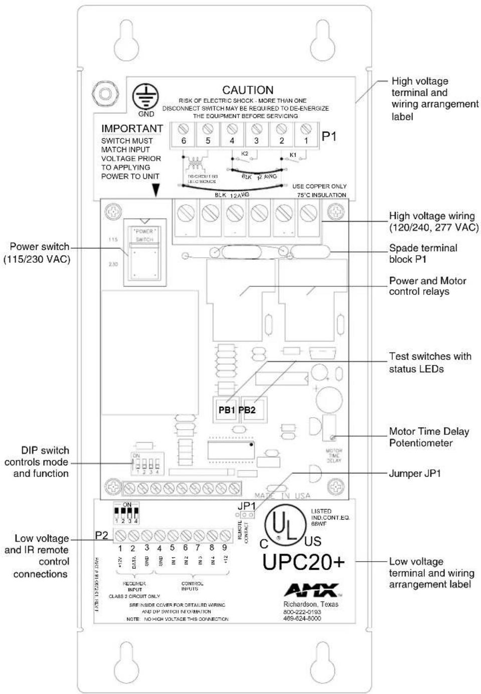
FIG. 1 UPC20+

NOTE
The UPC+ cover contains information on high voltage wiring, low voltage wiring, and DIP switch settings.
Specifications
| UPC20+ Specifications | |
| Power Self-powered when used with 110/220 VAC | |
| Power input (for control board) 120/240V ~, 50-60 Hz, 0.05/0.025A-or-12 VDC, 0.2A max | |
| Power output per relay • 20A @ 120/240V ~, 50-60 Hz (RESISTIVE LOAD)• 6A @ 277V ~, 50-60 Hz (FLUORESCENT BALLAST)• 1 HP @ 120V ~, 50-60 Hz (INDUCTIVE LOAD)• 2 HP @ 240V ~, 50-60 Hz (INDUCTIVE LOAD)Total Current through both relays CAN NOT exceed 20 amp. | |
| Maximum operating ambient temperature | 55°C |
| Approvals UL / C-UL / CE | |
| Includes • 1-, 2-, and 3-button logic modes• Local test switches with status LEDs• 120, 240, and 277 VAC control capability | |
| Inputs • 4 closure inputs, operation defined by mode.• One IR remote sensor input.• Motor Control mode alternates between the timed operation of the two power relays.• Power Control mode allows independent control of both power relays. | |
| Control Ports Two 2400 W power relays. Total combined current through both relays is 20 Amps. | |
| Input Power Switch (S1) | • Set this switch according to the high voltage wiring that will be connected to terminals 5 and 6 on P1. Refer to theP1 Terminal Connections section on page 7.• Set switch S1 to the line input voltage value used before applying power to the UPC20+. |
| High Voltage Terminal Block (P1) | High voltage input and output wiring for motor or power control. |
| Low voltage and Control Terminal Block (P2) | Contact closure, open-collector or CMOS logic level remote control wiring. Inputs 5 - 8 are referenced to the common connection at pin 4. |
| Jumper JP1 Sets control mode of the unit to contact closure or remote sensor serial data. | |
| Test Switches (PB1 and PB2) | Provides local operation of relays K1 and K2 for testing power circuits or motors connected to the relay terminals. An LED indicates relay power applied. |
| Motor Time Delay Potentiometer (R8) | Only used in motor control modes. User adjusted for setting relay release time between 0 and 90 seconds. |
| DIP Switch (S2) | Provides selection of control mode options. See Motor Control Mode DIP Switch S2 Positions table on page 4 and Control Input Wiring to Connector P2 Terminals table on page 4 for control mode settings. |
| Enclosure Metal with black matte finish, knockouts for conduit. | |
| Dimension (HWD) | • 8.5" (10.5" including flange) x 4.5" x 2.2"• (220 mm (270 including flange) x 110 mm x 60 mm) |
| Weight | 3.0 lbs. (1.4 kg) with flange |
| Options | 12 VDC power supply (for 277 VAC applications) |
Control Options Modes
ATTENTION INSTALLER
(UNIT WILL NOT WORK UNTIL DIP SWITCHES ARE SET)
SEE CHART ON LID TO SET
DIP SWITCHES FOR ACTIVE MODE
FIG. 2 UPC20+ inoperative mode warning label

If UPC20+ is powered up when changes are made to Dip Switch settings, then power must be cycled before changes can take effect.
Motor Control mode
The table list options and connections for motor control. DIP switch settings provide 1, 2 or 3 button remote control contact arrangements. This mode is typically used for screen and drape motor control.
In motor control mode, only one power relay (motor) can be energized at a time. When switching from one direction to another, the first motor is automatically turned off and a half-second delay is inserted before the other motor will turn on.
Once a motor is turned on, it will automatically be turned off after the amount of time determined by the motor time delay potentiometer, R8. Delay time can range from 0 to 90 seconds. It is typically set to allow direction limit switches to operate, or to reach the desired position.
| Motor Control Mode DIP Switch S2 Positions | |||
| 1 2 | 3 4 Control Mode | ||
| On On Off On Single button | |||
| Off Off Off On 2-button | |||
| Off On Off On Momentary On/Off | |||
- Single Button Mode operates with one pushbutton in a sequence: Up, Stop, Down, Stop and so on for each successive button press.
- Two/Three Button Mode operates with two pushbuttons, one for Up and one for Down.
- Momentary On/Off operates only when the button is pressed.
Control Input Wiring to Connector P2 Terminals
| 4 5 6 | 7 | 8 Control Mode | |||
| Common | Up | Down | Stop | N/A | Two, three button |
| Common | Up/Stop/Down | N/A | N/A | N/A | Single button |
Power Control mode
The tables below specify the DIP switch settings for momentary, latching, 2-button On/Off, and (momentary or latching) operation of K1 and K2.
| Power Control Mode DIP Switch Positions S2 | ||||
| 1 2 3 4 | Control Mode | |||
| On On | On On Momentary On/Off | |||
| Off On | On On Latching On/Off | |||
| On Off | Off On Two-Button On, Off | |||
| On Off | On On #1 Momentary, #2 Latching | |||
| Off Off | On On #1 Latching, #2 Momentary | |||
| Control Input Wiring to P2 Terminals | |||||
| 4 5 6 | 7 8 Control Mode | ||||
| Common | #1 On/Off | #2 On/Off | N/A | N/A | Momentary, Latch On/Off |
| Common | #1 On | #2 On | #1 Off | #2 Off | Two-Button On/Off |
Remote Sensor Control mode
The UPC20+ can also be controlled via the serial output from an AMX IR sensor. Remote sensor mode is selected by setting jumper JP1 to the "Remote" position (jumper on the left 2 pins), as shown in FIG. 3. (The jumper must be in position when power is applied to the UPC20+).

FIG. 3 JP1 mode settings

If motors of any kind are used, do not set to a Power Control mode. When a Power Control mode is selected, both relays can be on at the same time. Motors can be severely damaged if this happens.
When controlled by a remote sensor, the UPC20+ is in 2, 3-button timer motor control mode. When the timing potentiometer R8 adjusted to zero ohms (no time delay), the remote sensor provides momentary control.
A 3-bit code (radio code) set on DIP switch S2 associates an AMX handheld remote control with a UPC20+. This allows up to 8 UPC20+ and IR sensors to be used in the same room without interfering with one another. It is possible to control 2 separate UPC20+'s with one handheld remote control. The 4th switch of DIP switch S2 on the PCB selects between the two UPC20+'s. The table below lists the results of the 16 possible DIP switch selections in remote sensor mode.
The following table lists the DIP switch settings for Remote Sensor Mode.
| DIP Switch Settings for Remote Sensor Mode | |||||
| Sw. 1 Sw. | 2 Sw. 3 Sw. | 4 Radio | Code | UPC20+ | |
| Off Off Off Off 0 First | |||||
| On Off Off Off 1 First | |||||
| Off On Off Off 2 First | |||||
| On On Off Off 3 First | |||||
| Off Off On Off 4 First | |||||
| On Off On Off 5 First | |||||
| Off On On Off 6 First | |||||
| On On On Off 7 First | |||||
| Off Off Off On 0 Second | |||||
| On Off Off On 1 Second | |||||
| Off | On Off On 2 Second | ||||
| On | On Off On 3 Second | ||||
| Off Off On On 4 Second | |||||
| On | Off On On 5 Second | ||||
| Off | On On On 6 Second | ||||
| On | On On On 7 Second | ||||
Channel codes (Remote Sensor mode)
The table below lists the 5 AMX channel codes and their function in the UPC20+ when in Remote Sensor mode.
| Channel Codes and Functions | |
| Channel | Function |
| 6 Stop (K1 | and K2) |
| 0 #1 up (K1) | |
| 1 #1 down (K2) | |
| 7 #2 up (K1) | |
| 2 #2 down (K2) | |
Installation
P1 Terminal Connections
Low voltage power (see the table below) for internal circuitry is provided from an on-board transformer, powered by an external 120 or 240 VAC source. An onboard switch is used to select input voltage. When using the UPC20+ for 277 VAC control, the on-board internal circuitry is powered by a separate 120/240 VAC line, or from an optional 12 VDC power supply.
| P1 Terminal Connections | ||
| Terminal | Input/Output Function | |
| 1 | Output Load 1 out | |
| 2 | Input Line 1 in | |
| 3 | Output Load 2 out | |
| 4 | Input Line 2 in | |
| 5 | Input Neutral to transformer on PCB which supplies low voltage | |
| 6 | Input Line to transformer on PCB which supplies low voltage | |
K1 and K2 are the power and motor control relay connections to P1 terminals 1 and 2, 3 and 4, respectively. Each relay is capable of switching the following loads:
● Resistive Load 20 Amps at 120/240 VAC
● Fluorescent Ballast 6 Amps at 277 VAC
- Inductive Load 1 HP
The maximum total combined current through both relays is 20 Amps. There are two 12-gauge jumpers that are wired to supply board power at 120/240 VAC, and to connect the common terminals of the relays. The jumpers are removed as needed according to the wiring options selected.
P2 Terminal Connections
The table below defines the inputs and outputs for Terminal P2.
| P2 Low Voltage Terminal Inputs/Outputs | |
| Terminal | Input/Output |
| 1 +12 VDC out | |
| 2 Serial data in (IR sensor) | |
| 3 Ground | |
| 4 Ground (common) | |
| 5 Input | 1 |
| 6 Input | 2 |
| 7 Input | 3 |
| 8 Input | 4 |
| 9 +12 VDC in | |
Control Mode
The table below defines the control mode functions for Inputs 1 and 2. TheUPC20+ Control Mode Functions for Inputs 3 and 4 table on page 9 defines the control mode functions for Inputs 3 and 4.
UPC20+ Control Mode Functions for Inputs 1 and 2
| Control Mode | S2 Switch Setting | R8 Motor Time Delay Pot | Input 1(P2, pin 5-to GND) | Input 2(P2, pin-6 to GND) |
| Motor, Single Button | On, On, Off, On | Minimum Push 1 = | load 1 "on"Release 1 = load 1 "off"Push 1 again = load 2 "off" | Not used |
| Minimum Push 1 = | load 1 "on"Release 1 = load 1 "off after delay time out"Push 1 again = load 2 "on"Release 1 again = load 2 "off after time out"Note: pushing again restarts cycle. | Not used | ||
| Motor, 2/3 Button | Off, Off, Off, On | Minimum Push 1 = | load 1 "on"Release 1 = load 1 "off" | Push 2 = load 2 "on"Release 2 = load 2 "off" |
| Maximum Push 1 = | load 1 "on"Release 1 = load 1 "off after time out"Note: both loads cannot be On at the same time. | Push 2 = load 2 "on"Release 2 = load 2 "off after time out" | ||
| Motor, Momentary | Off, On, Off, On | Minimum Push 1 = | load 1 "on"Release 1 = load 1 "off" | Push 2 = load 2 "on"Release 2 = load 2 "off" |
| Maximum Push 1 = | load 1 "on"Release 1 = load 1 "off"Note: No delay on release. | Push 2 = load 2 "on"Release 2 = load 2 "off" | ||
| Power, Momentary | On, On, On, On | Minimum Push 1 = | load 1 "on"Release 1 = load 1 "off" | Push 2 = load 2 "on"Release 2 = load 2 "off" |
| Maximum Push 1 = | load 1 "on"Release 1 = load 1 "off" | Push 2 = load 2 "on"Release 2 = load 2 "off" | ||
| Power, Latching | Off, On, On, On | Minimum Push 1 = | load 1 "on"Release 1 = load 1 "still on"Push 1 again = load "off"Release 1 again = load "still off" | Push 2 = load 2 "on"Release 2 = load 2 "still on"Push 2 again = load "off"Release 2 again = load "still off" |
| Maximum Push 1 = | load 1 "on"Release 1 = load 1 "still on"Push 1 again = load "off"Release 1 again = load "still off"Note: Both loads can be On at the same time (time delay does not affect). | Push 2 = load 2 "on"Release 2 = load 2 "still on"Push 2 again = load "off"Release 2 again = load "still off" | ||
| UPC20+ Control Mode Functions for Inputs 1 and 2 (Cont.) | ||||
| Control Mode | S2 Switch Setting | R8 Motor Time Delay Pot | Input 1(P2, pin 5-to GND) | Input 2(P2, pin-6 to GND) |
| Power, 2 Button | On, Off, Off, On | Minimum Push 1 = | load 1 "on"Release 1 = load 1 "still on" | Push 2 = load 2 "on"Release 2 = load 2 "still on" |
| Maximum Push 1 | = load 1 "on"Release 1 = load 1 "still on"Note: Both loads can be On at the same time. | Push 2 = load 2 "on"Release 2 = load 2 "still on" | ||
| Power, Momentary #1, Latching #2 | On, Off, On, On | Minimum Push 1 = | load 1 "on"Release 1 = load 1 "off" | Push 2 = load 2 = "on"Release 2 = load 2 "still on"Push 2 again = load 2 "off"Release 2 again = load 2 "still off" |
| Maximum Push 1 | = load 1 "on"Release 1 = load 1 "off"Note: Delay time does not effect loads. | Push 2 = load 2 = "on"Release 2 = load 2 "still on"Push 2 again = load 2 "off"Release 2 again = load 2 "still off" | ||
| Power, Momentary #1, Latching #2 | Minimum Push 1 | = load 1 "on"Release 1 = load 1 "still on"Push 1 again = load 1 "off"Release 1 again = load 1 "still off" | Push 2 = load 2 "on"Release 2 = load 2 "off" | |
| Maximum Push 1 | = load 1 "on"Release 1 = load 1 "still on"Push 1 again = load 1 "off"Release 1 again = load 1 "still off"Note: Delay time does not affect loads. | Push 2 = load 2 "on"Release 2 = load 2 "off" | ||
| UPC20+ Control Mode Functions for Inputs 3 and 4 | ||||
| Control Mode S2 | Switch Setting | R8 Motor Time Delay Pot | Input 1 (P2, pin 5-to GND) | Input 2 (P2, pin-6 to GND) |
| Motor, Single Button | On, On, Off, On | Minimum Not used | Not used | |
| Minimum Not used | Not used | |||
| Motor, 2/3 Button | Off, Off, Off, On | Minimum Not used | Not used | |
| Maximum Not used | Not used | |||
| Motor, Momentary | Off, On, Off, On | Minimum Not used | Not used | |
| Maximum Not used | Not used | |||
| Power, Momentary | On, On, On, On | Minimum Not used | Not used | |
| Maximum Not used | Not used | |||
| Power, Latching Off | On, On, On | Minimum Not used | Used | |
| Maximum Not used | Not used | |||
| Control Mode S2 | Switch Setting | R8 Motor Time Delay Pot | Input 1 (P2, pin 5-to GND) | Input 2 (P2, pin-6 to GND) |
| Power, Two Button | On, Off, Off, On | Minimum Push 3 = | load 1 "off"Release 3 = load 1 "still off" | Push 4 = load 2 "off"Release 4 = load 2 "off" |
| Maximum Push 3 | = load 1 "off"Release 3 = load 1 "still off" | Push 4 = load 2 "off"Release 4 = load 2 "off" | ||
| Power, Momentary #1, Latching #2 | On, Off, On, On | Minimum Not used | Not used | |
| Maximum Not used | Not used | |||
| Power, Latching #1, Momentary #2 | On, Off, On, On | Minimum Not used | Not used | |
| Maximum Not used | Not used | |||
High Voltage Wiring Options
Single circuit 120/240 VAC
Single circuit connections (FIG. 4) are for most motor and screen control applications.
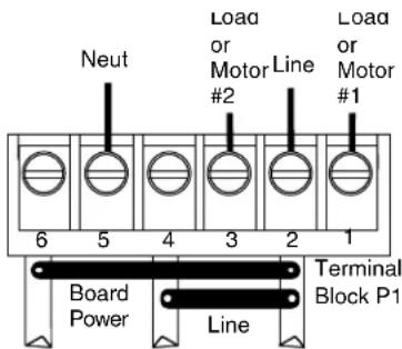
Line #1, Line #2, and Line to transformer are common.
FIG. 4 Single circuit 120/240 VAC power wiring
Dual circuit 120/240 VAC
Dual circuit connections provide power from two 120/240 VAC supply systems. FIG. 5 shows a dual circuit 120/240 VAC power wiring. Refer to FIG. 1 on page 2 for the location of the Terminal Block P1 on the circuit board.
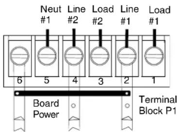
Line #1 in and Line to transformer are common. Line #2 in is an independent circuit.
FIG. 5 Dual circuit 120/240 VAC power wiring
Dual circuit 277 VAC
Dual circuit connections provide power from 277 VAC for fluorescent ballasts (FIG. 6). Circuit board power is provided by a separate 120/240 VAC high voltage circuit, or 12 VDC connected to terminals 1 and 6 on the low voltage terminal block. For dual circuit 120/240 VAC operation, remove the short 12 AWG wire jumper.
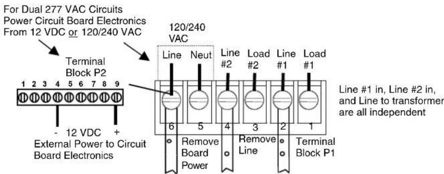
FIG. 6 Low voltage and 277 VAC high voltage wiring

If motors of any kind are used, do not set to a power control mode. When a power control mode is selected, both relays can be on at the same time. Motors can be severely damaged if this happens.
Wiring The UPC20+ to Either The IRX-DM+ Or IRX-SM+
Wire the UPC20+ to the sensor as shown in FIG. 7.

FIG. 7 Wiring diagram for UPC20+ to IRX-DM+ or IRX-SM+
Wireless IR Sensor Connection
The wireless IR sensor connections are located on P2, terminals 1 - 3. Terminal 1 is +12 VDC out, terminal 2 is serial data in, and terminal 3 is GND. The +12 VDC is short circuit protected, and the output supplies up to 25 mA for the remote sensor.
For dual circuit 277 VAC operation, remove both 12 AWG wire jumpers.
Installing the UPC20+
To install the UPC20+ unit:
- Mount the UPC20+ on a wall or solid surface in the location where it will be used; it can be mounted either horizontally or vertically.
- Remove the cover.
- Prepare terminal block P1.
a. Set power switch S1.
b. Configure jumpers according to high voltage wiring requirements.
- Install conduit. Provide conduit for high voltage, low voltage and control wiring requirements using the 0.5 inch or 0.75 inch conduit connector knockouts.
- Connect high voltage wiring to the terminal block P1.
- Connect control wiring.
a. Set control mode DIP switch S2 and control jumper JP1. Refer to the Control Options Modes section on page 4 for more detailed information.
b. Install wiring for contact closure or remote control mode.
- Test low voltage and high voltage wiring. Conduct tests to confirm proper installation and functions of desired control modes.
Installation

AMX reserves the right to alter specifications without notice at any time.
ARGENTINA • AUSTRALIA • BELGIUM • BRAZIL • CANADA • CHINA • ENGLAND • FRANCE • GERMANY • GREECE • HONG KONG • INDIA • INDONESIA • ITALY • JAPAN LEBANON • MALAYSIA • MEXICO • NETHERLANDS • NEW ZEALAND • PHILIPPINES • PORTUGAL • RUSSIA • SINGAPORE • SPAIN • SWITZERLAND • THAILAND • TURKEY • USA ATLANTA • BOSTON • CHICAGO • CLEVELAND • DALLAS • DENVER • INDIANAPOLIS • LOS ANGELES • MINNEAPOLIS • PHILADELPHIA • PHOENIX • PORTLAND • SPOKANE • TAMPA
3000 RESEARCH DRIVE, RICHARDSON, TX 75082 USA • 800.222.0193 • 469.624.8000 • 469-624-7153 fax • 800.932.6993 technical support • www.amx.com
041-004-2236 9/07 ©2007 AMX Corporation. All rights reserved. AMX, the AMX logo, the building icon, the home icon, and the light bulb icon are all trademarks of AMX Corporation. In Canada doing business as Panja Inc.
Last Revision: 09/12/07
- Operation/Reference Guide
- UPC20+
- Universal Power Controller
- AMX Limited Warranty and Disclaimer
- UPC20+ Wiring Requirements
- Table of Contents
- UPC20+ Wiring Requirements ....3
- Product Information ....1
- Installation 7
- Product Information
- Control Options Modes
- ATTENTION INSTALLER
- Motor Control mode
- Power Control mode
- Remote Sensor Control mode
- Channel codes (Remote Sensor mode)
- Installation
- P1 Terminal Connections
- P2 Terminal Connections
- Control Mode
- High Voltage Wiring Options
- Dual circuit 120/240 VAC
- Dual circuit 277 VAC
- Wiring The UPC20+ to Either The IRX-DM+ Or IRX-SM+
- Wireless IR Sensor Connection
- Installing the UPC20+
Brand : AMX
Model : UPC20+
Category : Electric controller