
810 - VCR MERIDIAN - Free user manual and instructions
Find the device manual for free 810 MERIDIAN in PDF.


| Product Type | Reference Video System (Projector + Scaler) |
| Brand | Meridian |
| Model | 810 |
| Projector Resolution | 4096 x 2400 pixels (10 megapixel) |
| Projector Technology | D-ILA (Direct-drive Image Light Amplifier) x 3 |
| Contrast Ratio | 10,000:1 (native) |
| Light Source | 825W Xenon lamp, average life 1500 hours |
| Scaler Processing | Marvell Qdeo™ technology, upscales to 4096x2400 |
| Projector Dimensions (W x D x H) | 663 x 827 x 342 mm (26.1 x 32.6 x 13.5 in) |
| Scaler Dimensions (W x D x H) | 437 x 343 x 87 mm (17.25 x 13.5 x 3.5 in) approx |
| Projector Weight | 55 kg (121 lb) excluding lens |
| Projector Power Consumption | 1230W (standby 2.7W) |
| Input Signals (Scaler) | 480i, 576i, 720p, 1080i, 1080p (24/50/60 fps), plus PC resolutions |
| Scaler Video Inputs | 1x HDMI, 1x DVI, 4x DVI output to projector |
| Control Interfaces | RS232, IR, Ethernet, Meridian Comms, USB, Trigger outputs |
| Lens Shift (vertical/horizontal) | Yes, dependent on lens assembly |
| Installation Tilt Angle | Up to ±90° |
| Maintenance - Filter Cleaning | Regular cleaning of front and side filters; replace if damaged (Service Kit SP7015AA) |
| Safety Features | Overheat protection, automatic shutdown, lamp protection |
| Warranty | 2 years against defects in material and workmanship |
Frequently Asked Questions - 810 MERIDIAN
User questions about 810 MERIDIAN
0 question about this device. Answer the ones you know or ask your own.
Ask a new question about this device
Download the instructions for your VCR in PDF format for free! Find your manual 810 - MERIDIAN and take your electronic device back in hand. On this page are published all the documents necessary for the use of your device. 810 by MERIDIAN.
USER MANUAL 810 MERIDIAN
810 Reference Video System User Guide
natural_image
Pure diagram of a rectangular layout with three inner rectangles and one circle, no text or symbols present.Important safety instructions – 810 Projector
Important information
WARNING: TO PREVENT FIRE OR SHOCK HAZARDS, DO NOT EXPOSE THIS APPLIANCE TO RAIN OR MOISTURE.
WARNING: THIS APPARATUS MUST BE EARTHED.
CAUTION: To reduce the risk of electric shock, do not remove cover. Refer servicing to qualified service personnel.
This projector is equipped with a 3-pin grounding type plug to satisfy FCC regulations. If you are unable to insert the plug into the outlet, contact your electrician.
FCC information (USA only)
CAUTION: Unapproved changes or modifications could void the user's authority to operate the equipment.
NOTE: This equipment has been tested and found to comply with the limits for a Class A digital device, pursuant to Part 15 of the FCC Rules. These limits are designed to provide reasonable protection against harmful interference when the equipment is operated in a commercial environment. This equipment generates, uses, and can radiate radio frequency energy and, if not installed and used in accordance with the instruction manual, may cause harmful interference to radio communications. Operation of this equipment in a residential area is likely to cause harmful interference in which case the user will be required to correct the interference at his own expense. Unapproved changes or modification could
Machine noise information (Germany only)
Changes Machine Noise Information Ordinance 3. GSGV, January 18, 1991: The sound pressure level at the operator position is equal or less than 70 dB (A) according to ISO 7779.
About the installation location
Do not install the projector in a place that cannot support its weight securely.
If the mounting is not sturdy enough, the projector could fall or overturn, possibly causing personal injury.
Important safeguards
Electrical energy can perform many useful functions. This unit has been engineered and manufactured to assure your personal safety. But IMPROPER USE CAN RESULT IN POTENTIAL ELECTRICAL SHOCK OR FIRE HAZARD. In order not to defeat the safeguards incorporated into this product, observe the following basic rules for its installation, use and service. Please read these Important Safeguards carefully before use.
- All the safety and operating instructions should be read before the product is operated.
- The safety and operating instructions should be retained for future reference.
- All warnings on the product and in the operating instructions should be adhered to.
- All operating instructions should be followed.
- Place the projector near a wall outlet where the plug can be easily unplugged.
- Unplug this product from the wall outlet before cleaning. Do not use liquid cleaners or aerosol cleaners. Use a damp cloth for cleaning.
- Do not use attachments not recommended by the product manufacturer as they may be hazardous.
- Do not use this product near water. Do not use immediately after moving from a low temperature to high temperature, as this causes condensation, which may result in fire, electric shock, or other hazards.
-
Do not place this product on an unstable cart, stand, or table. The product may fall, causing serious injury to a child or adult, and serious damage to the product. The product should be mounted according to the manufacturer's instructions, and should use a mount recommended by the manufacturer.
-
When the product is used on a cart, care should be taken to avoid quick stops, excessive force, and uneven surfaces which may cause the product and cart to overturn, damaging equipment or causing possible injury to the operator.
- Slots and openings in the cabinet are provided for ventilation. These ensure reliable operation of the product and protect it from overheating. These openings must not be blocked or covered. (The openings should never be blocked by placing the product on bed, sofa, rug, or similar surface. It should not be placed in a built-in installation such as a bookcase or rack unless proper ventilation is provided and the manufacturer's instructions have been adhered to.) For proper ventilation, separate the product from other equipment, which may prevent proper ventilation (see Positioning, page 13).
- This product should be operated only with the type of power source indicated on the label. If you are not sure of the type of power supply to your home, consult your product retailer or local power company.
- This product is equipped with a three-wire plug. This plug will fit only into a grounded power outlet. If you are unable to insert the plug into the outlet, contact your electrician to install the proper outlet. Do not defeat the safety purpose of the grounded plug.
- Power-supply cords should be routed so that they are not likely to be walked on or pinched by items placed upon or against them. Pay particular attention to cords at doors, plugs, sockets, and the point where they exit from the product.
- For added protection of this product during a lightning storm, or when it is left unattended and unused for long periods of time, unplug it from the wall socket and disconnect the cable system. This will prevent damage to the product due to lightning and power line surges.
- Do not overload wall sockets, extension cords, or
PORTABLE CART WARNING (symbol provided by RETAC)

S3126A
convenience receptacles on other equipment as this can result in a risk of fire or electric shock.
- Never push objects of any kind into this product through openings as they may touch dangerous voltage points or short out parts that could result in a fire or electric shock. Never spill liquid of any kind on the product.
- Do not attempt to service this product yourself as opening or removing covers may expose you to dangerous voltages and other hazards. Refer all service to qualified service personnel.
- Unplug this product from the wall outlet and refer service to qualified service personnel under the following conditions:
a) When the power supply cord or plug is damaged.
b) If liquid has been spilled, or objects have fallen on the product.
c) If the product has been exposed to rain or water.
d) If the product does not operate normally by following the operating instructions. Adjust only those controls that are covered by the Operation Manual, as an improper adjustment of controls may result in damage and will often require extensive work by a qualified technician to restore the product to normal operation.
e) If the product has been dropped or damaged in any way.
f) When the product exhibits a distinct change in performance - this indicates a need for service.
- When replacement parts are required, be sure the service technician has used replacement parts specified by the manufacturer or with the same characteristics as the original part. Unauthorised substitutions may result in fire, electric shock, or other hazards.
- Upon completion of any service or repairs to this product, ask the service technician to perform safety checks to determine that the product is in proper operating condition.
- The product should be placed more than 300mm away from heat sources such as radiators, heat
registers, stoves, and other products (including amplifiers) that produce heat.
- When connecting other products such as VCRs, and DVD players, you should turn off the power of this product for protection against electric shock.
- Do not place combustibles behind the cooling fan. For example, cloth, paper, matches, aerosol cans or gas lighters that present special hazards when over heated.
- Do not look into the projection lens while the illumination lamp is turned on. Exposure of your eyes to the strong light can result in impaired eyesight.
- Do not look into the inside of this unit through vents (ventilation holes), etc. Do not look at the illumination lamp directly by opening the cabinet while the illumination lamp is turned on. The illumination lamp also contains ultraviolet rays and the light is so powerful that your eyesight can be impaired.
- Do not drop, hit, or damage the light-source lamp (lamp unit) in any way. It may cause the light-source lamp to break and lead to injuries. Do not use a damaged light source lamp. If the light-source lamp is broken, ask your retailer to repair it. Fragments from a broken light-source lamp may cause injuries.
- The light-source lamp used in this projector is a high pressure lamp. Be careful when disposing of the lightsource lamp. If anything is unclear, please consult your retailer.
- Do not ceiling-mount the projector to a place which tends to vibrate; otherwise, the attaching fixture of the projector could be broken by the vibration, possibly causing it to fall or overturn, which could lead to personal injury.
- Use only the accessory cord designed for this product to prevent shock.
*DO NOT allow any unqualified person to install the unit.
Be sure to ask your retailer to install the unit (eg attaching it to the ceiling) since special technical knowledge and skills are required for installation. If installation is performed by an unqualified person, it may cause personal injury or electrical shock.
Power connection
The power supply voltage rating of this product is AC 110V – 120 V, AC 200V – 240V. The power cord used must conform to the power supply voltage. Use only the power cord designated by your retailer to ensure Safety and EMC. Ensure that the power cable used for the projector is the correct type for the AC outlet in your country. Consult your Meridian retailer for more details.
WARNING: Do not cut off the main plug from this equipment. If the plug fitted is not suitable for the power points in your home or the cable is too short to reach a power point, then obtain an appropriate safety approved extension lead or adapter or consult your retailer. If nonetheless the mains plug is cut off, dispose of the plug immediately, to avoid a possible shock hazard by inadvertent connection to the main supply. If a new main plug has to be fitted, then follow the instruction given below.
WARNING: THIS APPARATUS MUST BE EARTHED.
IMPORTANT:
The wires in the mains lead on this product are coloured in accordance with the following code: Green-and-yellow : Earth
Blue : Neutral
Brown : Live
As these colours may not correspond with the colored marking identifying the terminals in your plug, proceed as follows: The wire which is coloured green-and-yellow must be connected to the terminal which is marked with the letter E or the safety earth or coloured green or green-and-yellow. The wire which is coloured blue must be connected to the terminal which is marked with the letter N or coloured black. The wire which is coloured brown must be connected to the terminal which is marked with the letter L or coloured red.
V
Preface
EMC supplement
- This equipment is in conformity with the provisions and protection requirements of the corresponding European Directives. This equipment is designed for professional projector applications and can be used in the following environments.
Controlled EMC environment (for example purpose built broadcasting or recording studio), and the rural outdoors environment (far away from railways, transmitters, overhead power lines, etc).
In order to get the best performance and for electromagnetic compatibility we recommend using cables not exceeding the length indicated below. Longer cables may be used with clip-on ferrite assemblies. For exceptionally long runs, use optical DVI cabling.
Cables Type Length
Power cord Power supply cord 3.0m
DVI (X4) Cable Shielded cable 5.0m
USB Cable Shielded cable 2.0m
LAN Cable Shielded cable 2.0m
RS-232C Cable Shielded cable 1.6m
The current consumption of this apparatus is 9.705A at 115v; 4.35A at 230v.
WARNING
This is a Class A product. In a domestic environment this product may cause radio interference in which case the user may be required to take adequate measures. In case where the strong electromagnetic waves or magnetism are near the signal cable, the picture will contain noise. In such cases, please keep the cable away from the sources of the disturbance.
Important safety instructions – 810 Scaler
- Read the instructions.
- Keep these instructions.
- Follow all instructions.
- Do not use this apparatus near water.
- Clean only with a dry cloth.
- Install only in accordance with the manufacturer's instructions.
• Refer all servicing to approved service personnel. - Do not disassemble – no user-servicable parts inside.
This apparatus has been designed with Class 1 construction and must be connected to a mains socket outlet with a protective earthing connection (the third grounding pin).
The apparatus may be isolated from mains power either by unplugging the power connector from the rear of the unit, or by unplugging the connector at the opposing end of the power cord or cable from its supply outlet. As a result, either or both of these connectors should remain accessible.
Safety warnings
WARNING: TO REDUCE THE RISK OF FIRE OR ELECTRIC SHOCK, DO NOT EXPOSE THIS APPARATUS TO RAIN OR MOISTURE.
- Do not expose the unit to dripping or splashing.
- Do not place any object filled with liquid, such as a vase, on the unit.
- Do not place naked flame sources, such as lighted candles, on the unit.
To avoid overheating
- Leave at least 10cm around the equipment to ensure sufficient ventilation.
Do not position the unit:
- In direct sunlight.
- Near heat sources, such as a radiator.
- Directly on top of heat producing equipment, such as a power amplifier.
- On a soft surface, such as a carpet, which would obstruct the ventilation holes in the base.
To avoid interference
Do not position the unit:
- Near strong electrical or magnetic radiation, such as near a power amplifier.
Radio interference
FCC Warning: This equipment generates and can radiate radio frequency energy and if not installed and used correctly in accordance with our instructions may cause interference to radio communications or radio and television reception. It has been type-tested and complies with the limits set out in Subpart J, Part 15 of FCC rules for a Class B computing device. These limits are intended to provide reasonable protection against such interference in home installations.
EEC: This product has been designed and type-tested to comply with the limits set out in EN55013 and EN55020.

Contents
Introduction 1
810 Reference Video System 2
Specifications – Projector 4
Specifications - Scaler 5
Installing the 810 Projector 7
Unpacking 8
Precautions during use 9
Names and functions of parts 10
Positioning 13
Installing the projector and screen 1 5
Overlaying projected images 1 7
Anamorphic lens and actuator assembly 1 8
Installing the 810 Scaler 21
Unpacking 22
Connections 23
Connecting up 25
Setting up the 810 System 27
Configuration Wizard 28
Stage 1: Resetting the product 29
Stage 2: Projector settings 30
Stage 3: Scaler settings 32
Stage 4: Other settings 33
Configuring the sources 34
Adjusting the projector 36
Operating the 810 System 39
Remote control 40
Operating the 810 Scaler 41
Using presets 42
Operating the 810 Scaler from the front panel 45
Maintenance 47
Cleaning and replacing the filters 48
Routine servicing 50
Troubleshooting 51
Troubleshooting - 810 Projector 52
Operational problems 53
Image problems 54
On-screen display messages 55
Warnings using indicator lights 56
Service and guarantee 57
Index 59
viii
Preface
Copyright and acknowledgements
Sales and service in the UK
Meridian Audio Ltd
Latham Road
Huntingdon
Cambridgeshire
PE29 6YE
England
Tel (01480) 445678
Fax (01480) 445686
Meridian and Meridian Digital Theatre are registered trademarks of Meridian Audio Ltd.
Marvell is a registered trademark of Marvell or its affiliates. Qdeo is a trademark of Marvell or its affiliates.
This guide was produced by:
Human-Computer Interface Ltd,
http://www.interface.co.uk
Sales and service in the USA
Meridian America Inc
8055 Troon Circle
Suite C
Austell
GA30168-7849
USA
Tel (404) 344 7111
Fax (404) 346 7111
http://www.meridian-audio.com
Designed and manufactured in the UK
Meridian Audio Ltd
Latham Road
Huntingdon
Cambridgeshire
PE29 6YE
England
Copyright © 2009 Meridian Audio Ltd.
Part no: 810U/1 (P86502)
Introduction
This guide provides full information about unpacking the 810 Scaler and connecting it to the 810 D-ILA Projector and the other equipment in the system.

natural_image
Pure diagram of a rectangular object with three internal geometric shapes (rectangular, square, and circle) and no text or symbols.810 Reference Video System
The 810 Reference Video System consists of two parts: a powerful 10 megapixel (4096 x 2400) Ultra High Definition projector, unique in the home theatre industry, and an advanced scaler featuring Marvell Qdeo™ technology that upscales SD and HD sources to this stunning level of resolution for a smooth, flicker-free, cinematic experience. Indeed, the 810 system surpasses even industry Digital Cinema specifications, delivering a level of picture quality that is virtually never experienced outside a film-studio's preview theatre.
In the 810 Reference Video System the projector and scaler are operated as a single system. Serial data commands flow between the two units to select the appropriate projection and image processing parameters at both ends of the chain, so that the image will always be at its best, whether it is receiving it from DVD, HDTV, Blu-ray Disc or alternative sources. The projector is also configured from the scaler interface, which includes a built-in configuration web server, accessed via the scaler's Ethernet connection.
The 810 Projector
The 810 Projector comes with a newly developed 1.27", 4096 x 2400 pixel D-ILA (Direct-drive Image Light Amplifier) device, and achieves an ultra-high resolution of 9.83 million pixels – five times that of full HD.
It achieves a high contrast ratio of 10,000:1 (native) by combining the D-ILA device with WireGrid (an inorganic reflective polarising plate) that is employed in the new optical engine.
The 810 projector enables vertical and horizontal lens shift (dependent on lens assembly), which enables a larger degree of flexibility in the layout. It can also be installed at a tilt angle of up to ±90^ , which provides greater flexibility in the location of the projection screen.
The design is compact and light, and enables stacking – the projector weighs 55kg (excluding lens). It operates extremely efficiently to keep power consumption under 1.5 kW.
Each 810 Projector is individually calibrated with unique procedures developed by William Phelps.
It is supplied with the 810 Scaler, offering upscaling and rendering of HD and SD sources to incredible 10 megapixel resolution
The 810 Scaler
Where some scaling technologies still rely on copying adjacent pixels to handle upconversion, the 810 scaler is fully interpolative, and offers a significantly higher level of processing. A brand new design, featuring Marvell's powerful Qdeo™ processing technology, the scaler converts any digital source (480i to 1080p) up to full 10 megapixel resolution. Its quiet and natural video processing produces images that are free from noise and devoid of artefacts whether operating in 4:3, 16:9 or 2.35:1 modes.
The 810 scaler includes a new class of adaptive video format conversion technologies, accepting video resolutions from 480i to 1080p, 24 to 60 frames per second.
Incorporated in the technology is a complete set of noise and artefact reduction technologies. Per-pixel noise and compression artefact reduction removes noise typically inherent in digital video, while per-pixel motion-adaptive 3-D de-interlacing removes jaggies and eliminates feathering. Marvell's Adaptive Contrast Enhancement (ACE) and Intelligent Color Remapping (ICR) render rich and vivid images, optimising texture, detail, edges, contrast and colour, providing a consistent, immersive viewing experience for all types of content.
The scaler accepts both HDMI and DVI inputs and delivers a quad DVI path to the projector. In addition the unit features Meridian comms for full integration with a Meridian Digital Theatre system, RS232 and
USB maintenance ports for firmware upgrades (the latter allowing an update to be loaded via a memory stick) and an RS232 connection to the projector.
The scaler is a rack-mounting unit in the same style as Meridian's existing C Series of installation products and includes a vacuum fluorescent front-panel display with soft buttons that can be used to operate and configure the unit. Modelled on Meridian's successful G Series user interface, the display labels the buttons according to context.
Specifications – Projector
General
• Power supply: AC 110V – 120V, AC 200V – 240V 50/60Hz
• Power consumption: 1230W (Standby mode: 2.7W)
- Current consumption: Max 10.9A (AC 110V – 120V)
Max 6A (AC 200V – 240V)
• Calorific power 4428kJ/h (1058kcal/h)
• Air capacity - Intake: Approx. 3m^3 (106ft ^3 )/min
• Air capacity - Discharge: Approx. 3m ^3 (106ft ^3 )/min
- Allowable operating temperature range: 10°C to 35°C (50 – 95°F)
- Allowable operating humidity range: Less than 80% (no condensation)
- Allowable storage temperature range: -5^ to 60^ (23 - 140°F)
- Installation altitude: Operation guarantee: 2000m (6560ft) and below
Performance guarantee: 1500m (4920ft) and below
- Dimensions: 663 x 827 x 342mm (26.1 x 32.6 x 13.5in) (W x D x H)
• Mass: 55kg (121lb)
- Dimensions with anamorphic lens: 675 x 977 x 342mm (26.6 x 38.5 x 13.5in) (W x D x H)
Inputs
- Video input: DVI-D (dual link) 24 pins (supports 12-bit extended input) x 4 (supports HDCP*)
• LAN: RJ45 x 1
• USB: Type B (Slave) x 1
• RS-232C: D-sub 9 pins (male) x 1 (to scaler)
* HDCP is the abbreviation for High-bandwidth Digital Content Protection system. Images from the DVI input terminal may not be displayed due to HDCP specification changes.
Optical system
- Projection method: D-ILA analogue drive system x 3
- D-ILA element *†: 1.27" (4096x2400 pixels) x 3 pcs (total no. of pixels: 29,491,200 pixels)
- Projection lens: See lens data sheets for options
• Light-source lamp: 825W xenon lamp - Screen size: 2 – 7.6m (80 – 300in) approx (see lens data)
- Projection distance: Approx. 2.5 – 12m (8.2 – 39.4ft)
* D-ILA is the abbreviation for Direct drive Image Light Amplifier † D-ILA devices are manufactured using extremely high-precision technology. Pixel effectiveness is 99.99%. Only 0.01% or less of the pixels would either not light up or remain permanently lit up.
Signal system
- Input format: From 810 scaler
• DVI clock: to 165MHz (Single)
• (Rx clock): to 330MHz (Dual)
• Display resolution: 4096x2400
Notes
- Some open source software is embedded in this product. For more information, please contact Meridian's service dept.
- Specifications and appearance of this product may be subject to change for improvement without prior notice.
- Please note that some of the pictures and illustrations may have been abridged, enlarged or contextualised in order to aid comprehension. Images may differ from the actual product.
Specifications – Scaler
Supported formats
- Input formats: 480i, 576i, 720p, 1080i, 1080p; 24/50/60fps
• Colour formats: RGB, YCbCr444, and YCbCr422.
• Output formats: 4096x2400 to drive projector inputs - Supported PC resolutions: VGA (640x480), SVGA (800x600), XGA (1024x768), WXGA (1280x768), SXGA (1280x1024), UXGA (1600x1200), all 60Hz.
Processor technology
- Multiple Marvell Qdeo™ video processors under microprocessor control
Connections
• HDMI In
• DVI in
- Quad DVI Out
• RS232 Projector socket
• RS232 Control socket
- Maintenance RS232 socket for firmware upgrades
• USB port for firmware upgrades via memory stick
• Meridian Comms BNC
- Ethernet port (RJ45) – for future use
• IR sensor port for connection of G12 remote sensor
- Trigger output x 3: two are used to control the anamorphic lens slide; one trigger is spare and user configurable
Controls
- Soft Buttons x 5: take on different functions according to context, eg Setup, Projector Settings, Scaler Settings etc.
- Power, Display, Reset, Home and More front panel buttons
Enclosure
• 2U, 19in rack mounting, uniform with C Series
- 437 × 343 × 87mm (17.25 x 13.5 x 3.5in) (W x D x H) approx, not including protuberances
Meridian Audio reserves the right to amend product specifications at any time.
Introduction
6
Introduction
Installing the 810 Projector
This chapter explains how to install the 810 Projector. Please read the following carefully when installing this unit.
The 810 Projector is designed to be controlled and operated solely by the 810 Scaler. As a result it is not necessary to access the projector setup features directly. Refer to the subsequent chapters for set-up and operation instructions including calibration and installation.

natural_image
Pure diagram of a rectangular object with three internal circles, no text or symbols presentInstalling the 810 Projector
Unpacking
The 810 Projector is supplied with the following accessories:
• 3m power cord for the US, UK and EU markets.
- Warranty.
- This manual.
If any of these items are missing please contact your Meridian retailer.
Note: You should retain the packaging in case you need to transport the unit.
Optional accessories
• 810 service kit: SP7015AA
- Replacement lamp: SP7009AA
Precautions during use
Burning-in of D-ILA device
Do not allow the same still picture to be projected for a long time or an abnormally bright video image to be projected.
Do not project still images with a high brightness or high contrast on the screen for a long time. This video image could be burnt into the D-ILA device.
Pay special attention when projecting video games and computer program images.
Motion images such as normal video playback images do not pose the burning-in problem.
Viewing conditions – brightness of room
Shield the screen from direct sunlight or bright lights, such as by using a curtain. Images are best projected in a darkened room.
Do not view the screen for prolonged hours. Looking at a screen continually for a prolonged time is tiring to the eyes. Allow your eyes to rest at intervals.
Do not use this unit if the image is flickering due to the installation conditions or environment.
Operational environment
Do not use this projector in rooms with cigarette smoke or oily smoke. This may cause the unit to malfunction.
When mounting this projector to the ceiling check the temperature around the projector unit. When a heater is in use, the ceiling may reach a temperature higher than anticipated, leading to malfunction of the unit.
Maintenance procedures
Clean dirt on the cabinet with a soft cloth. In case of heavy soiling, soak a cloth in neutral detergent diluted with water, wring dry and wipe, followed by wiping again using a dry cloth.
Pay attention to the following to prevent the cabinet from deteriorating in condition, getting damaged, or the paint from coming off.
- Do not wipe with a stiff cloth
- Do not wipe with force
- Do not wipe with thinner or benzene
- Do not spray with volatile chemicals like insecticide
- Do not allow prolonged contact with rubber or plastic products
Removing dirt from the lens
Use commercial blowers or lens cleaning papers (for cleaning glasses and cameras).
IMPORTANT: Do not use fluid-type cleaning agents. This may lead to peeling of the surface coating film.
Lens surface is fragile. Avoid rubbing it hard or knocking it.
Gauging replacement time of components
This product contains consumable components, such as optical components and filters, required for maintaining the function of the product. The timing for replacing these components varies considerably according to the frequency and environment of use. For details on replacement of components please consult your authorised Meridian retailer.
Names and functions of parts
Front/Right Side
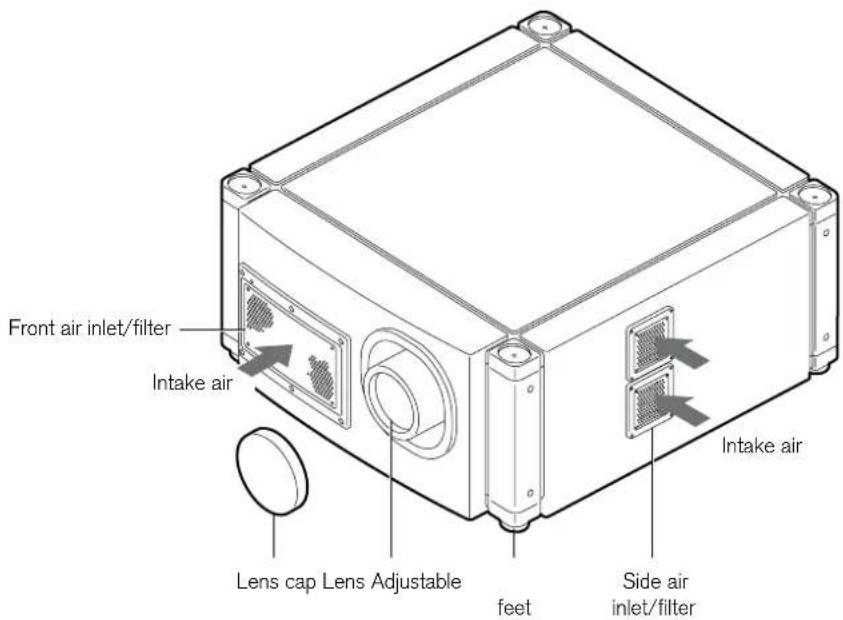
Front air inlet/filter
The air inlets absorb air to cool the interior of the projector. A filter is mounted inside the projector to remove dirt in the air that enters through the inlets. Clean the filter regularly (see Cleaning and replacing the filters, page 48).
CAUTION: Do not block the air inlets with papers, cloth, or soft cushions. Doing so may cause heat to build up inside the projector and result in fire or malfunction.
Lens cap
Fit the cap on the lens when this projector is not in use to prevent the lens from becoming dirty.
CAUTION: Do not project images with the lens cap attached. The lens cap may be deformed due to the heat, or the projector may malfunction.
Lens
(Several lens options are available for this projector.) Remove the lens cap before projection.
Adjustable feet (x 4)
Adjust the feet until the projector is level. The adjustable range is 20 mm for each. See Adjusting the inclination, page 14.
Side air inlet/filter
The air inlets absorb air to cool the interior of the projector. A filter is mounted inside the projector to remove dirt in the air that enters through the inlets. Clean the filter regularly (see Cleaning and replacing the filters, page 48).
Rear
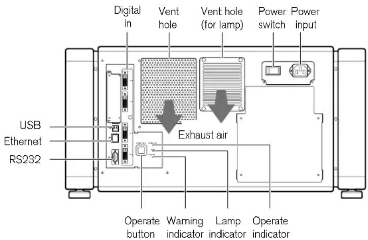
Digital in [DVI 1 to 4]
These are the input terminal for video signals. Connect to the video output terminals of the 810 scaler.
Vent hole
Warm air exits from the hole after cooling the projector.
CAUTION: Do not block the vent holes. Doing so may cause heat to trap inside the projector and result in fire or malfunction.
Vent hole (for lamp)
Warm air exits from the hole after cooling the lamp.
Power switch
Use this to turn ON/OFF the main power supply of the projector unit.
Power input
Connect the supplied cord to this terminal.
Operate indicator
Gives the following information:
Indicator Description
Lit (Red) Standby mode.
Lit (Green) Power is supplied.
Blinking (Red) In cooling (cool down) mode.
Blinking (Green) The projected image is temporarily hidden.
For details on indicator displays during warnings, refer to Warnings using indicator lights, page 56.
Lamp indicator
This indicator lights up when the lamp time exceeds 1400 hours. You may wish to arrange for this light to be visible.
For details on indicator displays during warnings, refer to Warnings using indicator lights, page 56.
A lamp life message appears on screen when the lamp time has exceeded 1500 hours.
Installing the 810
Projector
Warning indicator
This indicator lights up when abnormality occurs on this projector. For details, refer to Warnings using indicator lights, page 56.
Operate button
Pressing this button for one second or longer when in the standby mode (main power supply is ON) turns on the power of the projector unit. Pressing it for one second or longer when the power is ON switches the projector to the standby mode.
RS232
This interface is for connection to the 810 Scaler.
Ethernet
This port should be led out to an accessible point for service access.
USB
This port should be led out to an accessible point for service access.
Positioning
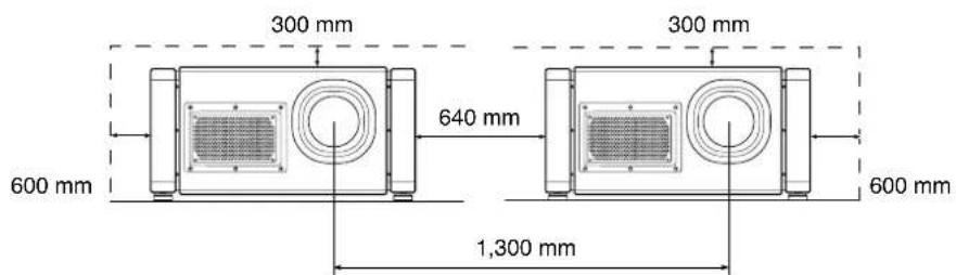
Recommended minimum space requirements
Do not use a cover that may enclose the projector or block the air inlets/vent holes. Allow sufficient space around the unit.
When this unit is enclosed in a space with dimensions as indicated below, ventilate the space accordingly so that the internal and external temperatures remain the same. Smaller enclosures may be used but ventilation must be sufficient. You may wish, for example, to couple the projector vents directly to vents in the enclosure with at least the same dimensions.
Check the temperature under both normal and exceptional environmental conditions to avoid risk of overheating.
When using a single projector
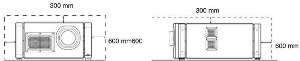
When using two projectors side by side
When the projector is suspended
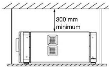
To mount the projector to the ceiling, mount a suitable shelf to the ceiling, then install the unit on the shelf. For safety, any maintenance work should be carried out on an adjustable platform that can be raised to a suitable height for access.
CAUTION: Special expertise and techniques are required for mounting this unit. Be sure to ask your retailer or a specialist to perform the installation.
Projector installation
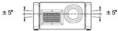
You can install this projector up to ±90^ .
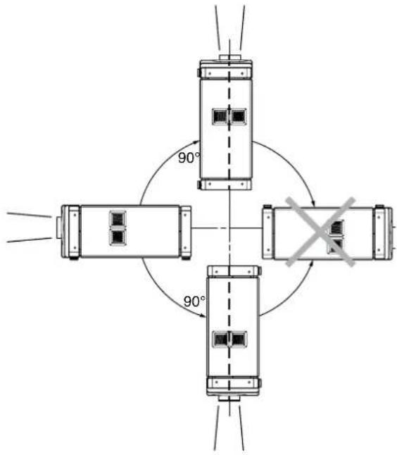
Images will be properly displayed if the horizontal angle is within the range of ±5^ .
CAUTION: To ceiling-mount this unit, special expertise and skills are necessary. Be sure to employ the authorized retailer or specialized work contractors for installation.
The projector cannot be installed upside down.
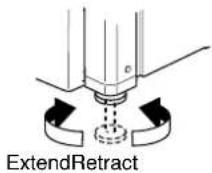
Adjusting the inclination
Adjust the horizontal angle of the projector.
Lift the projector and turn the adjustable foot in the direction indicated by the arrow to extend or retract the foot. The adjustable range is 20 mm.
Installing the projector and screen
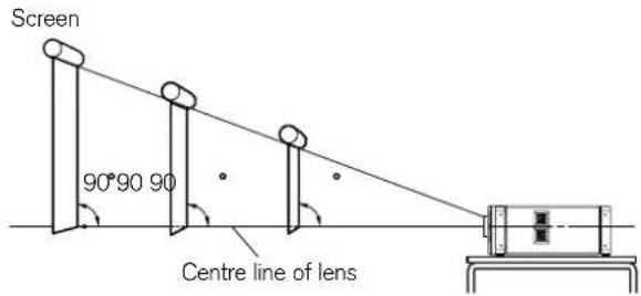
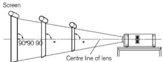
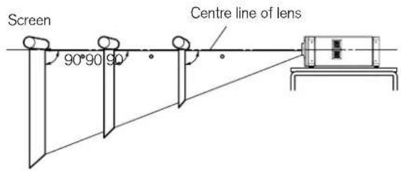
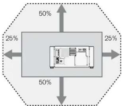
It is recommended that this projector be installed at right angles to the screen. You can shift the projection screen position vertically and horizontally with some optional lenses available for this projector as shown below. (See lens documentation)
When upward shift amount is up to 50% (Lens S only)
Install the projector so that the lower end of the projection screen is at the same height as the centre of the lens.
When there is no upward/downward shift
Install the projector such that the center of the projection screen is at the same height as the centre of the lens.
When downward shift amount is up to 50% (Lens S only)
Install the projector such that the upper end of the projection screen is at the same height as the centre of the lens.
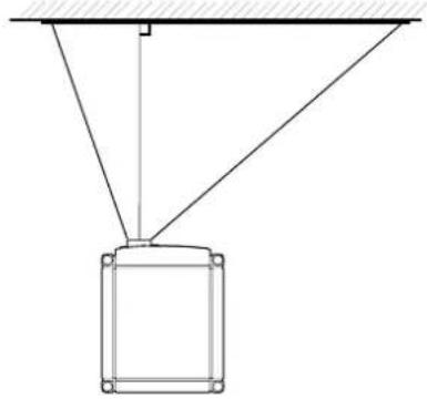
When shift amount to the right is up to 25% (Lens S only)
Install the projector such that the centre of the lens is aligned with the 14 position from the left edge of the screen.
natural_image
Simple line drawing of a suspended object with diagonal lines and a rectangular frame (no text or symbols)When there is no shift to the left or right
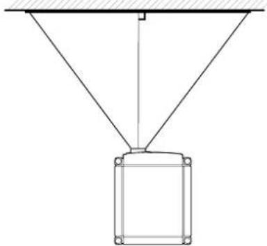
Install the projector such that the centre of the lens is aligned with the centre of the screen.
natural_image
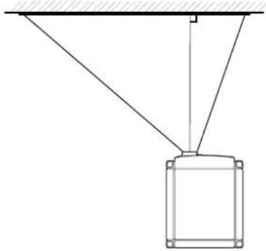
Simple line drawing of a suspended rectangular frame with diagonal lines and a horizontal support line above (no text or symbols)When shift amount to the left is up to 25% (Lens S only)
Install the projector such that the centre of the lens is aligned with the 14 position from the right edge of the screen.
natural_image
Simple line drawing of a suspended object with diagonal lines and a rectangular base (no text or symbols)Movable range of projected image (Lens S)
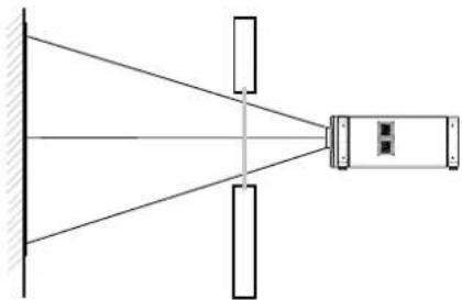
When light passes through the glass of a projection booth
natural_image
Diagram of a projector setup with beam path and screen (no text or symbols)NOTE: When light passes through the glass, the quantity of light decreases. Make sure that the glass of the projection booth is not in more than one piece.
Do not use any material at all if possible.
If glass is used, mount it at an angle to reduce reflections. Adjust the glass angle as well as the installation angle of this unit accordingly to prevent image degradation due to diffuse reflection.
Overlaying projected images
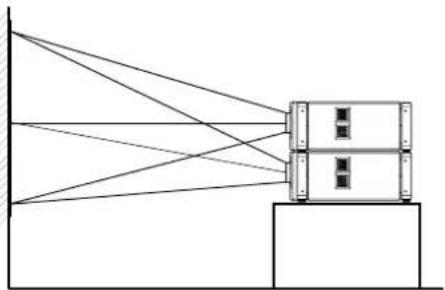
Projecting images by stacking projectors
The lens shift feature enables you to use up to three stacked projectors at the same time.
Stacking projectors enhances the brightness level, and helps to provide images that are sufficiently bright even when the venue is relatively large or well-lit.
natural_image
Diagram of a device with beams connecting to a central box (no text or symbols)CAUTION: When the projectors are stacked together during use, ensure that the installation site is sufficiently strong and there is proper air cooling around the projectors. Take the necessary measures to prevent the projectors from toppling or falling off so as to ensure safety during emergency situations, such as earthquakes, and to prevent accidents from occurring. For details, please consult your authorised retailer.
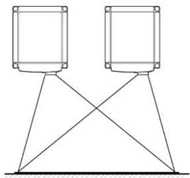
Projecting images by arranging projectors side by side
The lens shift feature enables you to use up to two projectors arranged side by side.
Arranging two projectors side by side enhances the brightness level, and helps to project images that are sufficiently bright even when the venue is relatively large or brightly illuminated.
When projecting images by arranging the projectors side by side, adjust the shift amount of both projectors accordingly to superimpose the images.
natural_image
Pure electrical circuit lines without any symbolsNOTE: When using the projectors by arranging them side by side, ensure that the installation site is sufficiently strong and there is proper air cooling around the projectors. For details, please consult your Meridian retailer.
Anamorphic lens and actuator assembly
The following instructions explain how to fit the optional anamorphic lens to the Meridian 810 Projector.
Please refer to the Iscoscope Owner and Setup Guide for setting up the anamorphic lens assembly.
Components
The anamorphic lens kit includes these components:
- Shelf assembly (sled and fixing bracket)
- Lens (in case)
- Assembly guide
• Isco user guide
• Accessories box which includes: Allen keys, Remote control, Power supply unit with adapters, Jack plug kit, Fixings and washers
Step 1
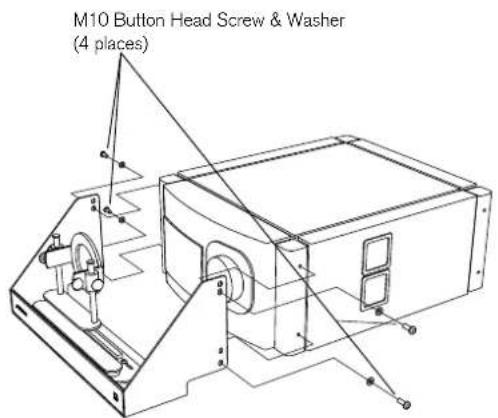
- Remove the dust caps from the four mounting positions.
- Position the shelf.
- Screw in the M10 button head screws using the supplied 6mm Allen key.
Use the upper fixing positions when the projector is mounted above the screen centre line.
Step 2
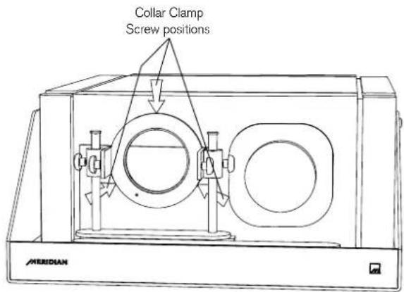
- Loosen off the three collar clamp screws until they are little more than finger tight using the supplied 2mm Allen key.
Step 3
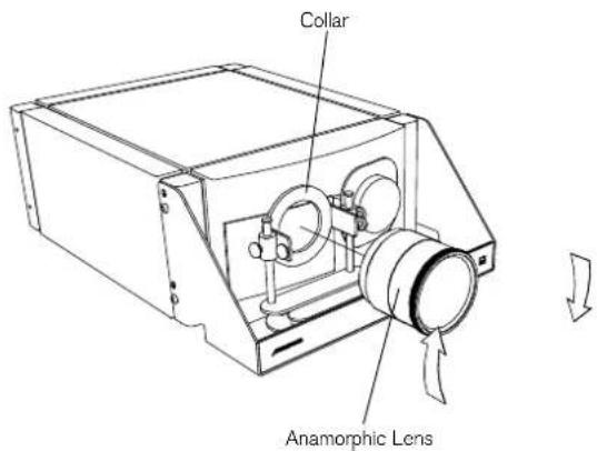
- Screw the anamorphic lens into the collar.
If the three collar clamp screws are not loosened to finger tight, the anamorphic lens will be difficult and tight to screw home.
Step 4
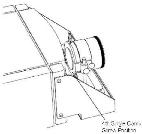
Once the lens is screwed firmly home:
- Undo the three collar clamp screws fully and rotate lens until correctly aligned.
- Tighten all three collar clamp screws and the additional fourth single clamp screw located at rear of the mounting collar.
Use the 2mm Allen key for all screws.
Step 5
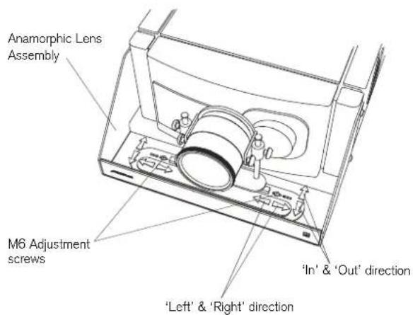
The entire anamorphic lens assembly can be adjusted out (away from the projector), in (towards the projector), and left and right, by loosening the M6 screws with the supplied 4mm Allen key.
Step 6
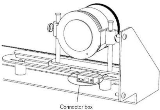
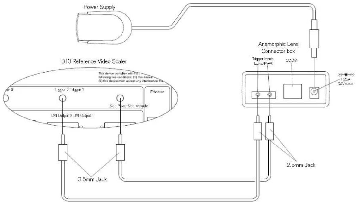
Connect the anamorphic lens assembly connector box to the 810 Scaler, as shown in the following diagram.
Installing the 810
Projector
Wiring diagram
Installing the 810 Scaler
This chapter explains how to install the 810 Scaler. It describes what you should find when you unpack the product, and how you should connect it to the other equipment in the system.
You should not make any connections to the product or to any other component in the system while the AC power supply is connected and switched on.

natural_image
Simple line drawing of a rectangular object with three circular holes, no text or symbols present.Unpacking
The 810 Scaler is supplied with the following accessories:
• 810 remote control with batteries.
- Power cord.
- This manual.
If any of these items are missing please contact your Meridian retailer.
Note: You should retain the packaging in case you need to transport the unit.
Mounting
The 810 Scaler is designed to be mounted in a standard 2U, 19in rack, uniform with Meridian C Series products.
Note that for adequate cooling, ensure that you do not obstruct the fan on the left-hand side of the unit, or the vent on the right-hand side of the unit.
Connections
Installing the 810 Scaler
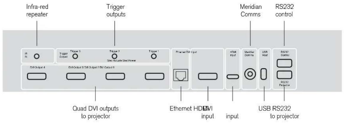
Video connections
Use this connection To connect to this
DVI Outputs 1 to 4 The corresponding DVI 1 to DVI 4 inputs on the 810 D-ILA Projector, using DVI cables.
HDMI Input The HDMI output of a video source, such as a Meridian G95 DVD Surround Receiver
System, using an HDMI cable. The sound channel is ignored.
DVI Input The DVI output of a video preamplifier or video source, using a DVI cable.
The video connections should be made with HD-quality DVI to DVI, HDMI to HDMI, or DVI to HDMI cables.
Meridian recommends cable lengths no longer than 27 feet (8m) using standard cable. For longer cable runs, an external equalizer/extender and good quality cable is recommended.
Please consult Meridian if optical fibre DVI links are to be used to verify we can meet the cable power specifications.
if you need the audio on your HDMI source, ie HDMI carries both, then you need a Meridian HD621 HDMI Audio Processor to split the audio off to drive a Meridian processor?
Control connections
Use this connection To connect to this
RS232 Projector The RS232-C input on the 810 D-ILA Projector.
RS232 Control A controller, such as a Crestron, for remote control of the 810 video system. For more information see the 810 RS232 Interface Guide, available separately.
RS232 Maintenance (front panel) For firmware updates.
Meridian Comms Meridian G Series or 800 Series equipment, or Meridian DSP loudspeakers.
IR IN A G12 IR Receiver, or approved alternative infra-red repeater.
Trigger 1, Trigger 2, Trigger 3 Other equipment, via mono 3.5mm jack plug outputs (tip hot) providing 12VDC. They are always low in standby. By default they are high for all sources, so can be used to bring another product out of standby. Alternatively you can program them to be high for specific sources; eg to control a projection screen. In systems with an anamorphic lens sled, Trigger 1 and Trigger 2 are dedicated to Sled Power and Sled Actuate respectively.
Ethernet For future expansion.
USB Host (back and front panel) For future expansion.
The RS232 connections should be made using RS232 Male-Male Null Modem serial cables.
Connecting up
Installing the 810 Scaler
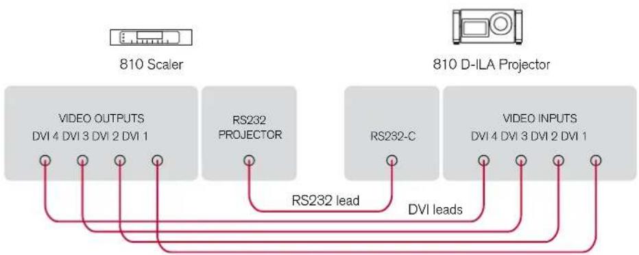
To connect to the 810 D-ILA Projector
flowchart
graph LR
    A["810 Scaler"] --> B["810 D-ILA Projector"]
    B --> C["VIDEO OUTPUTS\nDVI 4 DVI 3 DVI 2 DVI 1"]
    B --> D["RS232 PROJECTOR"]
    B --> E["RS232-C"]
    B --> F["VIDEO INPUTS\nDVI 4 DVI 3 DVI 2 DVI 1"]
    C --> G["RS232 lead"]
    D --> G
    E --> H["DVI leads"]
    F --> H
- Connect the RS262 Projector to connect the 810 S84er to the DVI 1 to DVI 4 inputs on the 810 D-ILA Projector, using DVI leads, ensuring that you link connectors with matching numbers.
• Scaler to the RS232-C connector on the Projector, using an RS232 Male-Male Null Modem Cable.
To connect to a video source
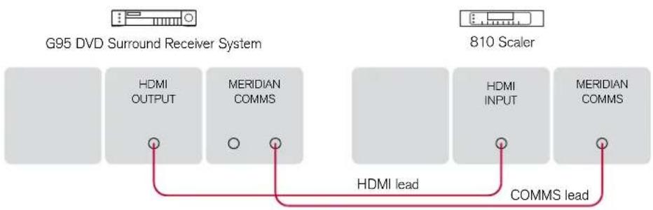
flowchart
graph LR
    A["G95 DVD Surround Receiver System"] --> B["HDMI OUTPUT"]
    A --> C["MERIDIAN COMMS"]
    D["810 Scaler"] --> E["HDMI INPUT"]
    D --> F["MERIDIAN COMMS"]
    B --> G["HDMI lead"]
    C --> H["COMMS lead"]
    E --> I["COMMS lead"]
- Edmside does the HDMI is at Meridian to provide to such as to the HDMI input on the 810 Scaler, using an HDMI lead.
Alternatively, if the video source provides a DVI output, use the DVI input on the 810 Scaler.
a G95 DVD Surround Receiver System, connect together the COMMS sockets using the Comms lead provided with the other product. - Configure the source to use the appropriate input; see Configuring the sources, page 34.
Installing the 810 Scaler
To connect to other Meridian G Series or 800 Series equipment
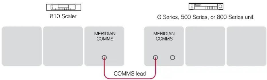
flowchart
graph LR
    A["810 Scaler"] --> B["MERIDIAN COMMS"]
    C["G Series, 500 Series, or 800 Series unit"] --> D["MERIDIAN COMMS"]
    B --> E["COMMS lead"]
    D --> E
    style E fill:#f9f,stroke:#333
In a system of Meridian products the products should be linked together in a chain, via the COMMS sockets, using the Comms leads supplied with each product. The sequence in which you connect the units is not important.
Note: Do not, under any circumstances, connect any equipment other than Meridian G Series or 800 Series to the socket marked COMMS on the back of the product.
Setting up the 810 System
This chapter explains how to configure the 810 Scaler using the Configuration Wizard from the front panel.
It then explains how to set up the 810 Reference Video System using the remote control in conjunction with the on-screen display.

natural_image
Simple line drawing of a rectangular object with three circular holes, no text or symbols present.Setting up the 810 System
Configuration Wizard
The Configuration Wizard leads you through the correct sequence to configure your Scaler/Projector.
Alternatively, you can skip between the configuration stages, which allow you to reset the configuration, or configure the sources or other settings of the Scaler/Projector.
To run the Configuration Wizard
- If necessary press Power to put the scaler into standby.
- Press More.
The display shows:
Wizard
- Press Wizard.
Follow the sequence of configuration stages described in the following pages, pressing Next to proceed after completing each stage.
At any stage in the Configuration Wizard the following options are available:
To do this Press
Go back to an earlier configuration option Back
Go to the next configuration option Skip
Return to the title screen for the stage Home
Exit from the configuration menus Power
Stage 1: Resetting the product
To reset the configuration
- Press Wizard.
The display shows the title screen for stage 1:
1: Reset Settings Enter SkipExit
- Press Enter to proceed or Skip to go stage 2.
If you pressed Enter the display shows:
Reset all settings? No Yes
- Press Yes to proceed or No to exit.
The display briefly confirms:
Reset to default
When you have reset the scaler:
Either:
- Press Skip to proceed to configuring projector settings, as described in the next section.
Or:
- Press Power to return to standby.
Stage 2: Projector settings
The Configuration Wizard provides access to the essential projector settings, needed to obtain a visible on-screen display.
Once these settings have been configured correctly, further settings can be adjusted using the remote control and on-screen display, as described in Adjusting the projector, page 36.
To configure the projector settings
Either:
- Press Skip after resetting the product; see Stage 1: Resetting the product, page 29.
Or: - Press Wizard; see Configuration Wizard, page 28.
- Press Skip to skip past the Reset settings menu.
The display shows the title screen for stage 2:
- Press Enter to proceed or Skip to go to stage 3.
The display shows the first projector setting, Test Pattern, and the current value of that setting, Off:
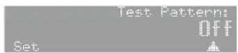
- Press Next or Back to step between settings.
The options are summarised in the table on the next page.
To change a setting
- Press ▲ or ▼ to step through the alternative values for the setting.
To move to the next setting
- Press Source.
When you have finished configuring projector settings:
Either:
- Press Next on the last option of the last source (Force Signal) to proceed to configuring settings, as described in the next section.
Or:
- Press Power to return to standby.
Projector settings
The following table summarises the projector settings:
| Setting Values Default Description | |||
| Test Pattern | Off, Colour bars,Crosshatch 1,Crosshatch 2,Staircase, Ramp, Flat. | Off | Displays a test pattern. |
| Display Mode | Cross, Single, Double. | Cross | Single displays just the input from DVI 1; this option is useful when connecting a source such as a PCs. Double displays the input from DVI 1 on the left and DVI 3 on the right. Cross displays DVI 1 top left, DVI 2 top right, DVI 3 bottom left, and DVI 4 bottom right. |
| Input Levels | Standard or Enhanced. | Standard Standard is appropriate for input levels of 0 to 255. Enhanced is for input levels of between 16 and 235. | |
| Lamp Power | 80%, 83%, 86%, 89%, 91%, 94%, 97%, 100%. | 80% | Specifies the lamp power. The lamp life will be extended at lower powers. |
| Back Colour | Black or Blue. Black | Specifies the background colour. | |
| Frame Lock | Off or On. Off | This synchronizes all video input signals for picture projection. | |
| Flip H, Flip V | Off or On. Off, Off | Allows you to compensate for an inverted image; eg if the projector is behind the screen. | |
| Gamma | B, C, A. | B | Sets the Gamma to A: 2.2, B: 1.8, or C: 2.6. The system is calibrated for a Gamma of 1.8. |
| Force Signal | 1 to 6 or Off. 6 | Should be set to 6 for use with the 810 scaler. When connecting a PC directly to the projector another setting may be required:1: 4096x2400, None, Dual: 1 screen, Dual Link2: 4096x2400, None, Single: 1 screen, Single Link3: 2048x2400, 2Stripe, Dual: 2 screens, Dual Link4: 2048x2400, 2Stripe, Single: 2 screens, Single Link5: 2048x1200, Cross, Dual: Centre cross, Dual Link6: 2048x1200, Cross, Single: Centre cross, Single Link7: 1024x2400, 4Stripe, Dual: Stripes, Dual Link8: 1024x2400, 4Stripe, Single: Stripes, Single Link | |
Setting up the 810
System
Stage 3: Scaler settings
The next stage allows you to install an update.
To configure the scaler settings
Either:
- Press Next after configuring the projector settings.
Or: - Press Wizard; see Configuration Wizard, page 28.
- Press Skip to skip past the Reset settings and Proj. settings stages.
The display shows the title screen for stage 3:
3: Scaler settings
Enter SkipBack
- Press Enter to proceed.
The only option is to update the firmware:
Firmware update:
Update?
No Yes.
- Insert a USB memory stick containing the MFU update file.
You can use either the back panel or front panel USB connector.
- Press Yes to proceed.
The display shows:
Firmware update:
Please wait
No Yes.
If no suitable update file is found the display shows:
Firmware update:
No MSD
Back
Otherwise it displays:
Firmware update:
Update successful
Enter SkipBack
When you have completed the update:
Either:
- Press Skip to proceed to configuring other settings, as described in the next section.
Or:
- Press Power to return to standby.
Stage 4: Other settings
The final stage allows you to configure other aspects of the product's operation.
To configure the other settings
Either:
- Press Next after configuring the projector settings.
Or:
- Press Wizard; see Configuration Wizard, page 28.
- Press Skip to skip past the Reset settings, Proj. settings, and Scaler settings stages.
The display shows the title screen for stage 4:
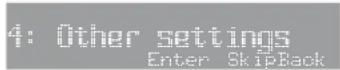
- Press Enter to proceed.
The first setting is displayed:

The settings are summarised in the table below.
When you have finished configuring the settings:
- Press Next to complete the Wizard.
The display shows:

Either:
- Press Exit to return to standby.
Or:
- Press Start to return to stage 1; see Configuration Wizard, page 28.
Option Values Description
| Lens slide | Off or On. | Enables the anamorphic sled. |
| Main system address | 1 to 8. | Advanced setting. |
| Product address | 1 to 8. | Advanced setting. |
| Use DHCP | No or Yes. | For configuration of the Ethernet port; for future expansion. |
IP address For configuration of the Ethernet port; for future expansion.
Setting up the 810 System
Configuring the sources
If you are using the 810 Scaler in conjunction with a Meridian system, you can use the Sources menu to configure each of the 12 Meridian sources.
- Press Setup on the remote control.
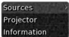
- Press ▶.
The Sources menu will be displayed:
| Sources | |
| Source (Cd) | CD> |
| Source (Radio) | RADIO |
| Source (Dvd) | DVD |
| Source (Aux) | AUX |
| Source (Disc) | DISC |
| Source (Tape) | TAPE |
| Source (Tv) | TV |
| Source (Cable) | CABLE |
| Source (Sat) | SAT |
| Source (Vcr1) | VCR1 |
| Source (Vcr2) | VCR2 |
| Source (Game) | GAME |
This shows a list of the standard 12 Meridian sources, corresponding to the 12 source selection keys on the MSR+ remote control:
CD, RADIO, DVD, AUX, DISC, TAPE, TV, CABLE, SAT, VCR1, VCR2, and GAME.
To configure a source
- Press ▲ or ▼ to highlight the source you want to configure.
- Press ▶.
The current settings for the source you selected will be displayed:
| Source (Dvd) | |
| Enabled | Yes |
| Blank | No |
| Colour | Bypass |
| Aspect Ratio | Manual |
| Input | HDMI |
| Preset | Bypass |
| Trigger 1 | Off |
| Trigger 2 | Off |
| Trigger 3 | Off |
| Legend | DVD |
To edit an option
- Press ▲ or ▼ to highlight the option you want to edit.
- Press ▶.
The alternative values for the option are displayed:
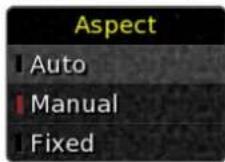
- Press ▲ or ▼ to highlight the value you want.
- Press Select to select it.
- Press ◀ to return to the previous menu.
The following table explains the function of each of the options:
| Option Values Default Description | |||
| Enabled | Yes or No. All Yes. | Whether the source appears in the list of sources. | |
| Blank | Yes or No. DVD=No,Sat=No, all others Yes. | Set to Yes to blank the display for audio-only sources. | |
| Colour | Bypass or Expand. | Bypass | Expand increases the colour range from 16-235 to 0-255 and can improve the colour depth/black level on some sources. Bypass leaves the colour range untouched. |
| Aspect Ratio | Auto, Manual, or Fixed. Manual | Specifies the effect of changing source on the Aspect Ratio. Auto selects the last valid aspect ratio used on that source. | |
| Input | HDMI, DVI, or LV. | DVD=HDMI, SAT=DVI, all others LV. | Specifies whether the source takes its video from the HDMI or DVI input. LV (Last Valid) leaves the input unchanged. |
| Preset | Bypass, Qdeo, or one of the seven user-defined presets. | Bypass | Allows you to associate a preset with the source to specify the video settings. |
| Trigger 1, Trigger 2, Trigger 3 | On, Off, Last Valid. | All Off | Specifies whether the trigger should be On or Off for the source. Last valid leaves it unchanged. |
| Legend | For example DVD. | As MSR+ key. | The legend displayed on the OSD for the source. Press Select to edit the name, ▶ or ◀ to step between characters, ▲ or ▼ to change a character, then Select to finish |
Setting up the 810 System
Adjusting the projector
To display the Projector menu
- Press Setup on the remote control.
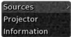
- Press ▼ to highlight Projector.
- Press ▶.
The Projector menu will be displayed:
| Projector | |
| Lens Shift | |
| Crop | |
| Display Mode | Cross |
| Input Level | Standard |
| Lamp Power | 80% |
| Back Colour | Black |
| Frame Lock | Off |
| Gamma | B |
| Flip H | Off |
| Flip V | Off |
| Force Signal | 6 |
Only the first two items can be adjusted from the on-screen display.
To adjust the lens shift
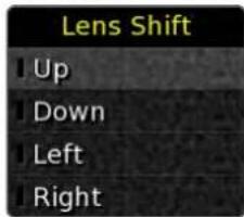
- Press ▲ or ▼ to highlight the direction you want to shift.
- Press ▶ or Select.
While you hold down the key the lens shift operates, and a red bar appears next to the option.
To adjust the image crop
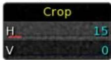
- Press ▲ or ▼ to highlight the dimension you want to crop.
- Press Select.
The bar changes from blue to red.
- Press ◀ or ▶ to edit the setting.
Each setting can be adjusted between 0 and 100. - Press Select.
Setting up the 810 System
To display Projector information
- Press Setup on the remote control.
- Press ▼ to highlight Information.
- Press ▶.
This shows service information, the Projector temperature, and the lamp time:
| Information | |
| Hardware | rev D |
| Firmware | 1.03 |
| Bootloader | 1.00 |
| Temp. | 39C |
| Lamp Time | 374h 5m |
If the items show Unavailable check the RS232 connection between the Scaler and Projector.
Setting up the 810
System
Operating the 810 System
This chapter explains how to operate the 810 Reference Video System using the remote control in conjunction with the on-screen display.

natural_image
Simple line drawing of a rectangular object with three circular holes, no text or symbols present.Operating the 810 System
Remote control
The 810 Scaler includes a remote control, which allows you to select sources, change preset, change the aspect ratio or zoom, or configure the unit using the on-screen display:
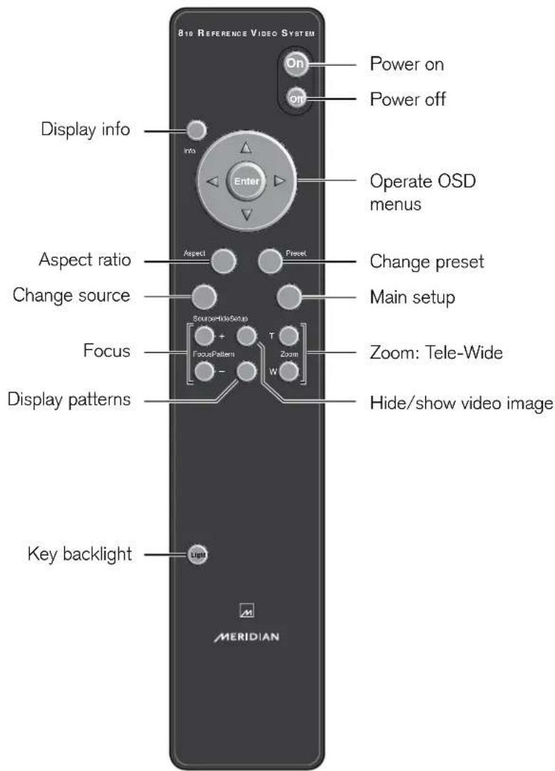
Operating the 810 Scaler
Changing the aspect ratio
- Press Aspect on the remote control.
The Aspect menu will be displayed:
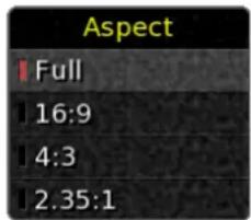
- Press ▲ or ▼ to highlight the aspect ratio you want to select.
- Press Enter.
The current aspect ratio will be indicated by a red bar.
The options are explained in the following table:
Option Description
Full Uses all pixels of the projector by converting the 16:9 aspect ratio to 17:10, resulting in a 5% horizontal stretch which is usually unnoticeable.
16:9 Displays a 16:9 image. There will be black bars above and below the image.
4:3 Displays a 4:3 image. There will be black bars each side of the image.
2.35:1 Anamorphic widescreen; only available with an anamorphic lens.
Changing the focus
- Press Focus + or - on the remote control.
Hiding the video image
- Press Hide on the remote control.
- Press Hide again to reveal the image.
Selecting a source
- Press Source on the remote control.
The Source menu shows a list of enabled sources:
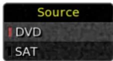
- Press ▲ or ▼ to highlight the source you want to select.
- Press Enter.
The current source will be indicated by a red bar.
Displaying a test pattern
- Press Pattern on the remote control.
This steps through the available patterns.
Zooming the image
- Press Zoom T or W on the remote control.
T (Tele) zooms in. W (Wide) zooms out.
Displaying information
- Press Info on the remote control.
Displays the input rate, input source, preset mode, and aspect ratio on the on-screen display.
Operating the 810 System
Using presets
The 810 Scaler allows you create up to seven user-defined presets. Each preset defines a range of video settings. For example, you could create a Football preset which gives settings optimised for watching live football matches on satellite television.
To display the presets
- Press Preset on the remote control.
The Presets menu will be displayed:
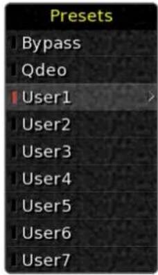
This shows a list of the two built-in presets, Bypass and Qdeo, and the seven user-definable presets.
The currently selected preset is indicated by a red bar.
To select a preset
- Press ▲ or ▼ to highlight the preset you want to select.
- Press Enter.
The preset will be indicated by a red bar.
To assign the currently selected preset to the current source
• From the Presets menu press ▶.
The following menu is displayed:
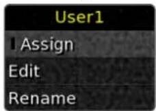
- Press Enter.
This will assign the current preset as the default preset for the source.
To edit the currently selected preset
• From the Presets menu press ▶.
- Press ▼ to highlight Edit:
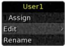
- Press ▶.
The Edit menu will be displayed:
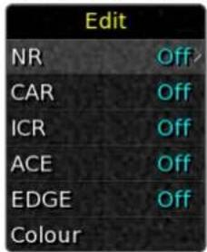
The following table explains the function of each of the options on the Edit menu:
| Option Values Default Description | |||
| NR | High, Medium, Low, or Off. | Off | Noise Reducer. Reduces the Additive White Gaussian Noise present in the incoming video. A per pixel motion adaptive filtering technique is used to reduce the noise. |
| CAR | On or Off. Off | Compression Artefact Reducer. Helps reduce blocking artifacts and mosquito noise caused by DCT-based video compression techniques like MPEG. For this mode to be most effective the source material should be unprocessed when it reaches the 810, as any prior upsampling will reduce its effectiveness. | |
| ICR | Vivid, Sky+Grass, Sky, Grass, Off. | Off | Intelligent Colour Remapper. Identifies specific colours of the image and makes them more vivid and visually pleasing. |
| ACE | High, Medium, Low, or Off. | Off | Adaptive Contrast Enhancement. Improves the contrast of a video stream on a frame by frame basis using statistics from the previous frame. It functions in different ways for different scenes (adaptive). It can bring out details from darker portions of a scene while preserving the brighter parts without washing them out. |
| EDGE | High, Medium, Low, or Off. | Off | Edge Enhancement. Sharpens the transients in a video signal. This has the effect of emphasizing the details, transitions and edges of the image. It can help improve soft images such as from Standard Definition material. |
| Colour See below. | All 50% | Allows you to adjust the image colour balance. | |
Operating the 810 System
To show the image colour settings
- Press ▲ or ▼ to highlight Colour on the Edit menu and press ▶.
The Colour menu is displayed:
| Colour | |
| Brightness | 50 |
| Contrast | 50 |
| Saturation | 50 |
| Tint | 50 |
| Cyan | 50 |
| Yellow | 50 |
| Magenta | 50 |
| Red | 50 |
| Green | 50 |
| Blue | 50 |
This shows the numeric setting of each of the ten image colour parameters, together with a graphical indication of the value as a blue bar under the name.
To edit the image colour settings
- Press ▲ or ▼ to highlight the setting you want to adjust.
- Press Enter.
The bar changes from blue to red.
- Press ◀ or ▶ to edit the setting.
Each setting can be adjusted between 0 and 100.
- Press Enter.
To rename the currently selected preset
• From the Presets menu press ▶.
- Press ▼ to highlight Rename.
- Press ▶.
- Press Enter to edit the name, ▶ or ◀ to step between characters, ▲ or ▼ to change a character, then Enter to finish
Operating the 810 Scaler from the front panel
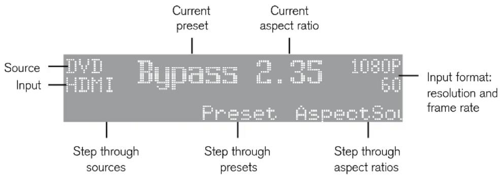
The 810 Scaler can also be operated from the front panel using the soft keys below the display:
Operating the 810
System
Operating the 810
System
Maintenance
Maintenance
natural_image
Pure diagram of a rectangular layout with three inner rectangles and one circle, no text or symbols present.Cleaning and replacing the filters
Turn off the power of the projector unit, and unplug the power cord when cleaning or replacing the filters.
Clean the filters regularly. If the filters are soiled, air intake efficiency may deteriorate, thus resulting in malfunction of the product.
Replace each filter with a new one if the filter fails to remove dust thoroughly or if it is damaged.
Failure to do so may cause dust to enter the projector and shadows to appear on the projected image.
The filters and associated components are supplied in the 810 Service Kit, part number SP7015AA.
If dirt has entered this product please consult your authorised Meridian retailer.
Side filter
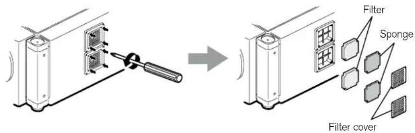
CAUTION: Remove the four screws on the inner side (these fasten the filter cover).
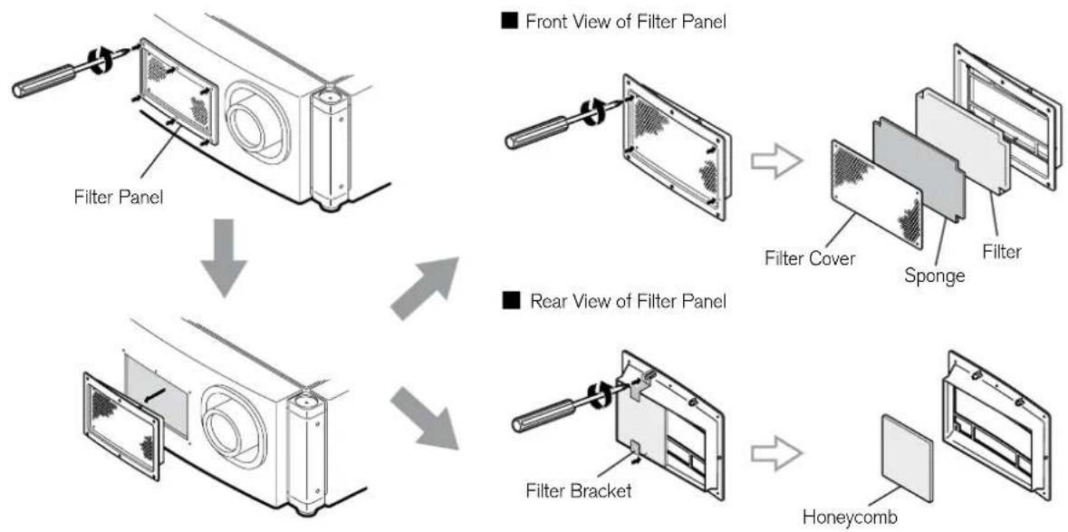
Front filter
flowchart
graph TD
    A["Filter Panel"] --> B["Front View of Filter Panel"]
    B --> C["Filter Cover"]
    C --> D["Sponge"]
    C --> E["Filter"]
    F["Filter Bracket"] --> G["Honeycomb"]
Procedure
- Remove the filter cover and filter panel
The filter is located at the front and side of the projector unit.
- Remove the sponge, filter, and honeycomb
Hold the centre of the filter using your fingers, and pull the filter toward you to remove it.
- Clean the sponge, filter, and honeycomb
Remove any dirt or dust using a vacuum cleaner.
CAUTION: Do not clean using a flammable air duster. This may cause fire.
- Mount the sponge, filter, and honeycomb
Mount the filter to the projector using the reverse of the removal procedure.
Finally, check to ensure that the filter cover and filter panel are firmly mounted.
NOTE: Mount the filter correctly. Failure to do so may cause the projector to malfunction.
The projector may stop operating if a damaged filter or filter panel is used. In this case, replace the filter or filter panel with a new one.
Routine servicing
Clean dirt from the cabinet
Use a soft cloth. In case of heavy soiling, soak a cloth in neutral detergent diluted with water, wring dry and wipe, followed by wiping again using a dry cloth.
Pay attention to the following to prevent the cabinet from deteriorating, getting damaged, or the paint from coming off.
- Do not wipe with a stiff cloth
- Do not wipe with force
- Do not wipe with thinner or benzene
- Do not spray volatile chemicals like insecticide
- Do not allow prolonged contact with rubber or plastic products
Remove dirt that is attached to the vent holes
Use a vacuum cleaner. Wipe using a cloth if a vacuum cleaner cannot be used. Leaving dust attached may prevent adjustment of the internal temperature and result in malfunction of the projector.
Clean dirt on the lens
Use commercial blowers or lens cleaning papers (for cleaning glasses and cameras).
Do not use fluid-type cleaning agents. This may lead to peeling of the surface coating film.
The lens surface is fragile. Avoid rubbing or knocking it.
Replacement of light source lamp
The light source lamp is a consumable item. Replace with a new lamp unit if the image appears dull or if the lamp burns out.
- When the lamp needs to be replaced soon, users will be notified through a message on the screen and the indicator. See Warnings using indicator lights, page 56.
- The life of the lamp used for this projector is about 1500 hours. This is the average life of lamps, and not a guaranteed value.
- The lamp life may not reach 1500 hours depending on the operating conditions.
- Deterioration progresses rapidly when the remaining lamp usable time is short.
- If the image is dark or colour tone abnormal, replace the lamp unit as soon as possible.
- For details on replacement of the lamp unit, please consult your Meridian retailer.
Troubleshooting
We expect you to achieve superb results with the 810 Reference Video System. If, however, you encounter any problems, either when installing it, or during operation, please check the following pages for suggested solutions.
If these suggestions fail to cure the problem, please contact your Meridian retailer for further assistance.

natural_image
Simple line drawing of a rectangular object with three circular holes, no text or symbols present.Troubleshooting – 810 Projector
Check the following points before sending this product for repair.
The following phenomena are not malfunctions.
If there is no abnormality on the screen when the phenomena below appear, they are not malfunctions
- The top or front part as well as the rear of the projector unit is hot
• A creaking sound is heard from the projector
• Device noise is heard from the interior of the projector
• There is colour bleeding on the screen
When the projector fails to run properly due to external interference, perform the following operations.
- Check to ensure that the power is shut down. Unplug the power cord, and insert again.
- Turn on the power again.
A sound may be heard when the lamp burns out. However, this is not a hazard.
D-ILA devices are manufactured using extremely high-precision technology. However, some of the pixels may not light up or remain permanently lit up.
Operational problems
There is no power
Is the power cord disconnected?
- Insert the power cord (plug) properly.
Is the main power supply switch turned on? - Turn on the main power supply switch of the projector unit.
Is the lamp in the cool down mode? - Turn on the power again after the cool down mode ends.
Is the lamp protection function triggered? (This function is triggered when the power shuts down such as during power failures.) - Wait till the temperature of the lamp has gone down. (Turn on the main power supply switch to run the fan and cool down the lamp.) Turn on the power after about 3 minutes.
Projector works when the power is turned on, but stops abruptly after a few minutes
Are the air inlets and vent holes blocked?
- Turn off the main power supply switch, and remove the blockage. After removing, turn on the power again.
Is the temperature of the room high? - Set the temperature of the room or the surrounding temperature of this projector to an appropriate level.
Are the filters dirty? - Clean the filters; see Cleaning and replacing the filters, page 48.
The remote control does not change the image settings
- Check that the RS232 projector control connection has been made between the Scaler and Projector.
- Check that the Information menu on the OSD Setup contains valid data. If the RS232 cable between the Scaler and Projector is not connected correctly the Information menu will display Unavailable on items that require a response from the Projector.
Image problems
Image is dark
Is the lamp near exhaustion?
- Check the Lamp Time indicator (see Warnings using indicator lights, page 56) or displayed screen message (see On-screen display messages, page 55). Obtain a replacement lamp from your Meridian retailer or contact Meridian's service department.
Video image does not appear
Is the lens cap removed?
- Remove the lens cap.
Is the scaler properly connected?
- Connect the scaler correctly.
Is the power to the connected devices turned on?
- Turn on the power to the connected devices.
Are correct signals being output from the connected devices?
- Check that the source you are using has the correct video input selected; DVI or HDMI.
- Configure the connected devices correctly.
Are the signals of the connected devices within operating range?
- Check to ensure that they are valid input signals, and input compatible signals accordingly.
Is the video image hidden?
- Press the Hide button on the remote control.
Video image is blurred
Is the projector out of focus?
- Adjust the focus using the Focus Lens setting on the 810 Scaler.
Is the projection distance too short or too long?
- Set it to a correct distance. See the lens documentation.
Colouring of the image is poor or distorted
Are the signals of the connected devices valid input signals?
- Check to ensure that they are valid input signals, and input compatible signals accordingly.
Is the input cable correctly connected?
- Connect the input cable correctly.
Projection position on the screen has shifted
Has the setup position of the projector been shifted?
- Check the setup position of the projector.
Image disappears suddenly
Are the video signals correctly input?
- Check the signals and connection.
The screen does not darken immediately when the projection has ended
The shutdown process is in progress
- Please wait for an addition 10 seconds for the shutdown process to complete
The quadrants of the image are in the wrong positions
- Check that the Quad DVI cables between the Scaler and Projector and connected correctly.
On-screen display messages
The following on-screen display messages are displayed when the lamp life has expired or when the input signal is invalid.
Lamp Time Over
Displayed when the lamp time has exceeded 1500 hours. The message is displayed for a period of 3 minutes during each projection.
- Replace with a new lamp unit.
For details on replacement of the lamp unit, please consult your Meridian retailer.
Out of Range
Displayed when there is input of video signals that cannot be used with this unit.
- Input video signals that can be used.
No Input
Displayed when the 810 Scaler is not connected to the DVI input ports, or when the scaler is connected but not powered on.
- Connect and power up the scaler.
Warnings using indicator lights
The lamp time and warning mode are indicated using the indicator light.
For details on indicator displays during normal operation, refer to Names and functions of parts, page 10.
No Standby Lamp Warning Description
1 * On - About time to replace lamp (Lamp time has exceeded 1400 hours)
2 * On - When the lamp life has expired (Lamp time has exceeded 1500
3 * On - When lamp does not light up and projection fails
4 † Blinking On When the lamp goes off during projection
5 † Blinking On Temperature around the lamp is high
6 † Blinking On When the internal temperature is unusually high
7 † - On When the external temperature is unusually high
8 † - On When the cooling fan stops running
9 † On When error occurs in the circuit operation
* The indicator lights up in red when the in standby mode, and in green when in the operating mode.
† The indicator lights up in red when in the warning mode, and blinks in red when in the cool down mode.
Measures when the warning mode appears
When the projector switches to the warning mode (Nos. 3 - 9), projection stops automatically, and the cooling fan runs for about 3 minutes.
After the cooling fan stops running, turn off the main power supply switch, and remove the power plug from the outlet.
Perform the following checks and take the corresponding measures.
No Check Measure
3 – 4 Check whether the projector has been subject to shock during operation. Turn on the power again.
4 – 9 Check whether the air inlets are blocked by objects. Allow some time for the projector to cool down.
Check to ensure that the external temperature of the projector is normal.
If the warning indication is displayed again, turn off the main power supply switch after the cooling fan stops running. Then remove the power plug from the power socket. Call your Meridian retailer for repair.
Service and guarantee
Service
The Meridian components have been carefully designed to give years of untroubled service. There are no user-serviceable parts inside the case, nor do the units require any form of maintenance.
In the unlikely event that your 810 Projector or Scaler fails to function correctly, it should be returned, in its original packaging, to your Meridian retailer.
In case of difficulty within the UK or USA please contact the appropriate sales and service address shown on page viii.
In case of difficulty outside the UK or USA, please contact your nearest Meridian retailer; see:
http://www.meridian-audio.com/find-a-retailer.aspx
No responsibility can be accepted for the 810 Projector or Scaler whilst in transit to the factory or an agent, and customers are therefore advised to insure the unit. When seeking service under guarantee, proof of the date of purchase will be required.
Guarantee
The 810 Projector and Scaler are guaranteed against defects in material and workmanship for two years from the date of purchase.
The guarantee is void if the 810 Projector or Scaler have been subject to misuse, accident, or negligence, or have been tampered with or modified in any way without the written authorisation of Meridian Audio Limited.
Note: Connecting anything other than the correct network lead to the Comms socket may cause damage to the 810 Scaler which will not be covered by this guarantee. Attempted servicing by unauthorised people may also invalidate this guarantee. Labour and carriage charges are not covered unless by local agreement.
Outside the UK, local warranty liability is restricted to equipment purchased within the territory. Our agents abroad are only under contractual obligation to service, under guarantee, equipment sold through them. They are entitled to make a non-refundable charge for any service carried out on other equipment.
This guarantee does not limit your statutory rights within the United Kingdom.
Troubleshooting
Index
A
accessories 8, 22
projector 8
ACE (Adaptive Contrast
Enhancement) 43
adjusting the inclination 14
anamorphic lens
assembly 18
connections 20
aspect ratio
16:9 41
2.35:1 41
4:3 41
Full 41
aspect ratio, changing 41
B
Back Colour 31
back panel connections 23
C
CAR (Compression Artefact Reducer) 43
cleaning the filter 48
colour preset options 43
COMMS, connecting 26
configuration, resetting 29
Configuration Wizard 28
configuring
other settings 33
projector settings 30
scaler settings 32
connections
anamorphic lens 20
between the projector and scaler 25
control 24
projector 11
scaler 23
to a video source 25
video 23
control connections 24
D
Display Mode 31
DVI
connecting 25
input 23
outputs 23
E
EDGE (Edge Enhancement) 43
Ethernet connection 24
F
filter, cleaning and replacing 48
firmware update 32
Flip H, Flip V 31
focus, changing 41
Force Signal 31
Frame Lock 31
front panel, operation from 45
front panel display 45
G
Gamma 31
guarantee 57
H
HDMI input 23
HDMI output, connecting 25
hiding the video image 41
|
ICR (Intelligent Colour Remapper) 43
image crop, adjusting 36
image problems 54
indicator light warnings 56
information 41
infra-red repeater 24
Input Levels 31
inputs
DVI 23
HDMI 23
installation
projector 7
scaler 21
L
Lamp Power 31
lamp time, displaying 37
Lamp Time Over message 55
lens shift, adjusting 36
M
Meridian Comms 24, 26
messages 55
Lamp Time Over 55
No Input 55
Out of Range 55
mounting 22
projector 13
scaler 22
N
No Input message 55
NR (Noise Reducer) 43
0
on-screen display messages 55
operating the scaler 41
from the front panel 45
other settings 33
Out of Range message 55
outputs
DVI 23
trigger 24
overlaying projected images 17
P
positioning, projector 13
precautions 9
preset options
ACE (Adaptive Contrast
Enhancement) 43
CAR (Compression Artefact
Reducer) 43
preset options (continued)
colour 43
EDGE (Edge Enhancement) 43
ICR (Intelligent Colour Remapper) 43
NR (Noise Reducer) 43
presets 42
assigning to a source 42
displaying 42
editing 42
renaming 44
selecting 42
projector 2
adjusting 36
adjusting the inclination 14
components 10
connections 11
information 37
installation 7
mounting 13
optional accessories 8
positioning 13
precautions 9
settings 30, 31
specifications 4
troubleshooting 52
unpacking 8
Projector menu 36
projector settings 30
Back Colour 31
Display Mode 31
Flip H, Flip V 31
Force Signal 31
Frame Lock 31
projector settings (continued)
Gamma 31
Input Levels 31
Lamp Power 31
Test Pattern 31
R
remote control 40
replacing the filter 48
resetting the product 29
routine servicing 50
RS232 connections 24
S
safety warnings vi
scaler 2
connections 23
installation 21
mounting 22
operating 41
settings 32
specifications 5
unpacking 22
screen
installing projector with 15
selecting a source 41
service 57
servicing 50
settings
projector 30
scaler 32
setting up 27
sources
assigning preset to 42
configuring 34
selecting 41
specifications
projector 4
scaler 5
T
Test Pattern 31
test patterns, displaying 41
trigger outputs 24
troubleshooting 51
image problems 54
operational problems 53
projector 52
U
unpacking
projector 8
scaler 22
updating the firmware 32
USB Host connection 24
V
video connections 23
video image, hiding 41
video source, connecting to 25
W
warnings 56
Z
zooming the image 41
Index
- Reference Video System User Guide
- Important safety instructions – 810 Projector
- Important information
- FCC information (USA only)
- Machine noise information (Germany only)
- About the installation location
- Important safeguards
- Power connection
- IMPORTANT:
- EMC supplement
- Cables Type Length
- WARNING
- Important safety instructions – 810 Scaler
- Safety warnings
- To avoid overheating
- To avoid interference
- Radio interference
- Contents
- Introduction 1
- Installing the 810 Projector 7
- Installing the 810 Scaler 21
- Setting up the 810 System 27
- Operating the 810 System 39
- Maintenance 47
- Troubleshooting 51
- Index 59
- Copyright and acknowledgements
- Sales and service in the UK
- Sales and service in the USA
- Designed and manufactured in the UK
- Introduction
- Reference Video System
- The 810 Projector
- The 810 Scaler
- Specifications – Projector
- General
- Inputs
- Optical system
- Signal system
- Notes
- Specifications – Scaler
- Supported formats
- Processor technology
- Connections
- Controls
- Enclosure
- Installing the 810 Projector
- Unpacking
- Optional accessories
- Precautions during use
- Burning-in of D-ILA device
- Viewing conditions – brightness of room
- Operational environment
- Maintenance procedures
- Removing dirt from the lens
- Gauging replacement time of components
- Names and functions of parts
- Front air inlet/filter
- Lens cap
- Lens
- Adjustable feet (x 4)
- Side air inlet/filter
- Rear
- Digital in [DVI 1 to 4]
- Vent hole
- Vent hole (for lamp)
- Power switch
- Power input
- Operate indicator
- Indicator Description
- Lamp indicator
- Warning indicator
- Operate button
- RS232
- Ethernet
- USB
- Positioning
- Recommended minimum space requirements
- Projector installation
- Adjusting the inclination
- Installing the projector and screen
- When upward shift amount is up to 50% (Lens S only)
- When there is no upward/downward shift
- When downward shift amount is up to 50% (Lens S only)
- When shift amount to the right is up to 25% (Lens S only)
- When there is no shift to the left or right
- When shift amount to the left is up to 25% (Lens S only)
- Movable range of projected image (Lens S)
- When light passes through the glass of a projection booth
- Overlaying projected images
- Projecting images by stacking projectors
- Projecting images by arranging projectors side by side
- Anamorphic lens and actuator assembly
- Components
- Step 1
- Step 2
- Step 3
- Installing the 810 Scaler
- Mounting
- Video connections
- Use this connection To connect to this
- Control connections
- Connecting up
- Setting up the 810 System
- Configuration Wizard
- To run the Configuration Wizard
- To do this Press
- Stage 1: Resetting the product
- To reset the configuration
- Stage 2: Projector settings
- To configure the projector settings
- To change a setting
- To move to the next setting
- Projector settings
- Stage 3: Scaler settings
- To configure the scaler settings
- 3: Scaler settings
- Stage 4: Other settings
- To configure the other settings
- Configuring the sources
- To configure a source
- To edit an option
- Adjusting the projector
- To display the Projector menu
- To adjust the lens shift
- To adjust the image crop
- To display Projector information
- Operating the 810 System
- Remote control
- Operating the 810 Scaler
- Changing the aspect ratio
- Option Description
- Changing the focus
- Hiding the video image
- Selecting a source
- Displaying a test pattern
- Zooming the image
- Displaying information
- Using presets
- To display the presets
- To select a preset
- To assign the currently selected preset to the current source
- To edit the currently selected preset
- To show the image colour settings
- To edit the image colour settings
- To rename the currently selected preset
- Operating the 810 Scaler from the front panel
- Maintenance
- Cleaning and replacing the filters
- Procedure
- Routine servicing
- Clean dirt from the cabinet
- Remove dirt that is attached to the vent holes
- Clean dirt on the lens
- Replacement of light source lamp
- Troubleshooting
- Troubleshooting – 810 Projector
- If there is no abnormality on the screen when the phenomena below appear, they are not malfunctions
- When the projector fails to run properly due to external interference, perform the following operations.
- A sound may be heard when the lamp burns out. However, this is not a hazard.
- Operational problems
- There is no power
- Projector works when the power is turned on, but stops abruptly after a few minutes
- The remote control does not change the image settings
- Image problems
- Image is dark
- Video image does not appear
- Video image is blurred
- Colouring of the image is poor or distorted
- Projection position on the screen has shifted
- Image disappears suddenly
- The screen does not darken immediately when the projection has ended
- The quadrants of the image are in the wrong positions
- On-screen display messages
- Lamp Time Over
- Out of Range
- No Input
- Warnings using indicator lights
- No Standby Lamp Warning Description
- Measures when the warning mode appears
- No Check Measure
- Service and guarantee
- Service
- Guarantee
- Index
- A
- B
- C
- D
- E
- F
- G
- H
- |
- L
- M
- N
- 0
- P
- R
- S
- T
- U
- V
- W
- Z
Brand : MERIDIAN
Model : 810
Category : VCR