
CH121 - Thermostat Fantini Cosmi - Free user manual and instructions
Find the device manual for free CH121 Fantini Cosmi in PDF.


User questions about CH121 Fantini Cosmi
0 question about this device. Answer the ones you know or ask your own.
Ask a new question about this device
Download the instructions for your Thermostat in PDF format for free! Find your manual CH121 - Fantini Cosmi and take your electronic device back in hand. On this page are published all the documents necessary for the use of your device. CH121 by Fantini Cosmi.
USER MANUAL CH121 Fantini Cosmi
FLUSH MOUNTING ROOM THERMOSTAT
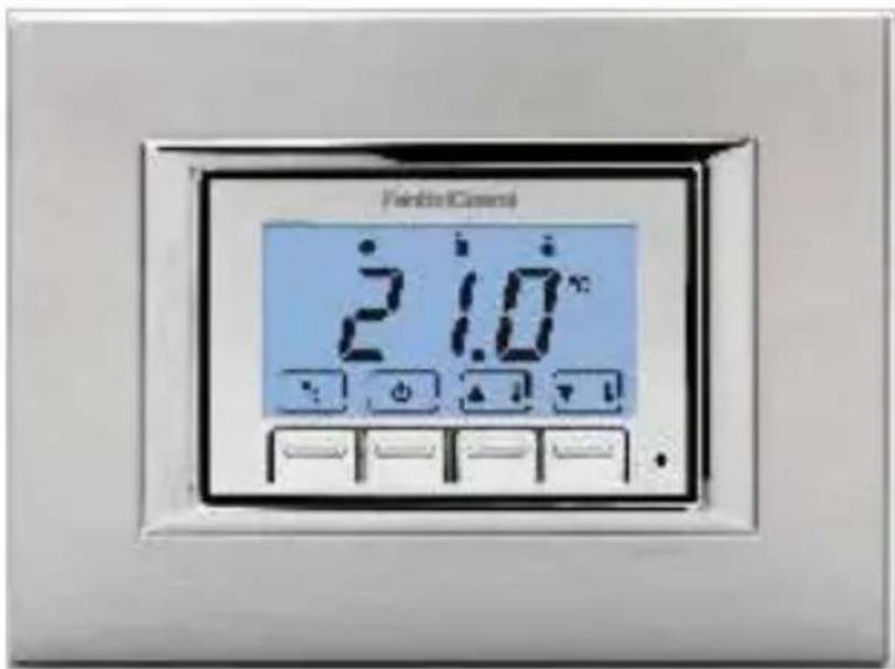
cover plate not included
2 1 H C
CONTENTS OF PACKAGE
1 thermostat
3 frames
■ 3 coloured covers, type A
■ 3 coloured covers, type B
■ 3 pairs of adapters
■ 1 pair of special adapters for Bticino Matix
2 screws
1 user manual
natural_image
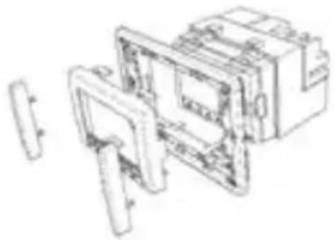
Technical line drawing of an electrical switchgear assembly (no text or labels)1 INSTALLATION
The CH121 chronothermostat must be installed in a 3-module recessed box, in the middle of the apartment, preferably 1.5 m off the ground. The required components, all included in the package, are used based on the plates available, according to the following table.
| COMPATIBLE PLATES | COVER* TYPE | FRAME TYPE | SIDE ADAPT-ERS * | TABS TO DETACH |
| Bticino Living International and Transizione Piana | B 1 NO NO | |||
| Bticino Living Light Air B 3 NO YES position “A+C” | ||||
| Bticino Light, Light tech B 1 NO NO | ||||
| Bticino Axolute A 1 NO NO | ||||
| Bticino Matix B 2 SI (dedicated) YES position “A” | ||||
| Vimar Idea and Rondò B 2 YES YES position “B” | ||||
| Vimar Plana and Eikon B 1 NO NO | ||||
| Vimar Eikon Evo A 3 NO | YES position “A” | |||
| Vimar Arké | A 3 NO NO | |||
| Gewiss Chorus One, Lux, Art | B 2 | NO | YES position “A” | |
| Ave sistema 45: Zama, Banquise, Yes, Ral | B 2 YES | NO | ||
| Ave sistema 44: Zama, Personal, Technopolymer | A 1 NO NO | |||
| Legrand Cross, Vela square, Vela round | B 2 NO | YES position “A” | ||
* N.B. COVER A available colours: white, silver and black; COVER B available colours: white, silver and black, for Bticino Matix white only.
CH121
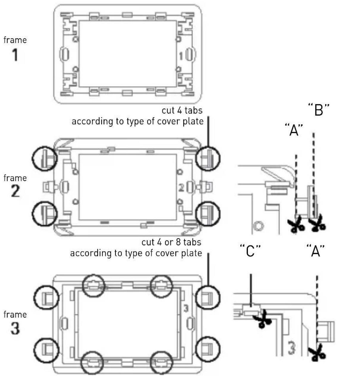
PERFORM THE FOLLOWING OPERATIONS:
- act on the master switch on the electric panel to cut power to the electrical system;
- when required, detach the tabs according to the type of plate;
- when required, mount the side adapters;
- fasten the chronothermostat to the suitable frame;
- mount the cover on the body of the chronothermostat;
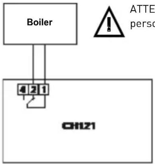
- connect the two wires of the boiler to terminals 1-2 of CH121;
- screw the frame onto the box using the provided screws;
- mount the plate;
- switch the electric system back on.
2 ELECTRICAL CONNECTIONS
flowchart
graph TD
    A["Boiler"] --> B["4 2 1"]
    B --> C["CH121"]
    D["ATTE person"] --> E["Warning Symbol"]
ATTENTION: installation must be carried out by qualified personnel
PLEASE NOTE: when CH121
is disconnected, the boiler contactremainsinitscurrent position.
CH121
3 INSERTION AND REPLACEMENT OF BATTERIES
Insert two AAA 1.5V alkaline long lasting batteries, of a good brand, paying attention to the marked polarities.
N.B. the life of the batteries is greatly affected by the type of use and the settings made by the user, especially the set back lighting switch-on time.
When the batteries are low, the symbol of the discharged battery flashes on the display: CH121 keeps working regularly, but the display does not light up.
If the batteries are completely discharged, the chronothermostat quits working, switching off the system and disabling the keys. "OFF" together with the symbol of the discharged batteries appear on the display until they are replaced.
To replace the batteries, remove CH121 from its housing, moderately pressing inwards and at the same time on both sides of the cover.
All parameters remain stored while the batteries are being replaced.
4 QUICK GUIDE FOR PROGRAMMING
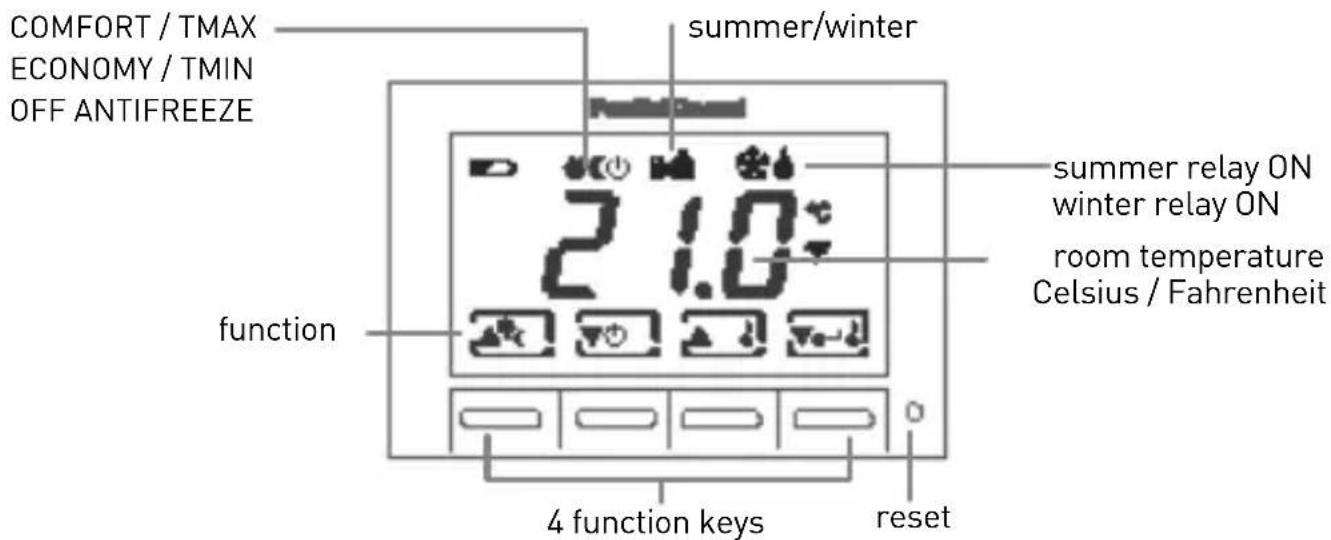
DESCRIPTION OF KEYS AND DISPLAY
The thermostat is equipped with 4 keys, the function of which varies depending on the situation. It is described by the symbol which appears on the display next to the key.
5 OPERATION
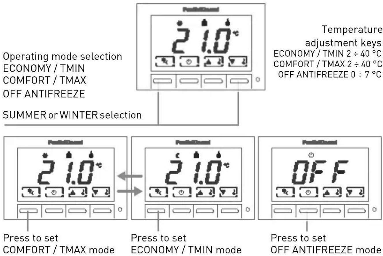
CUSTOMISE THE TEMPERATURE
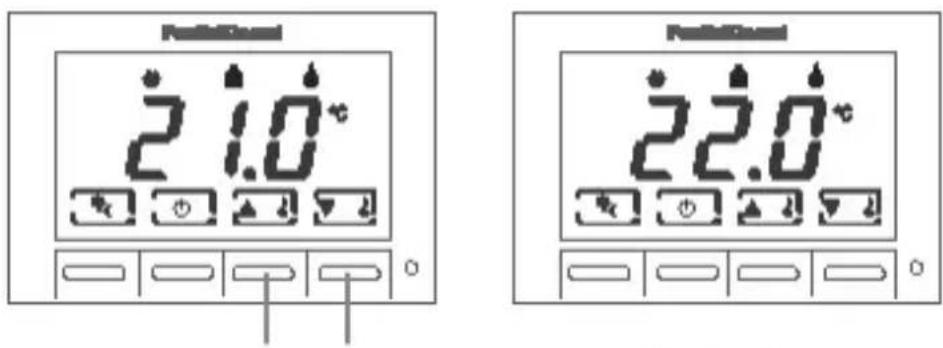
When you have set the operating mode press the two keys (increase or decrease) to set the temperature:
ECONOMY / TMIN 2 ÷ 40 °C
COMFORT / TMAX 2 ÷ 40 °C
OFF ANTIFREEZE 0 ÷ 7 °C
ANTIFREEZE temperature cannot be set in summer mode.
CH121
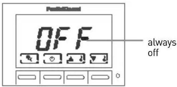
Press together, and keep pressed, to change back lighting duration.
You may choose the time during which back lighting remains on:
OFF → always off
1sec ..... 10sec
Increase\decrease back lighting duration. Press while keeping summer/winter and ON/OFF keys pressed.
SUMMER/WINTER SELECTION
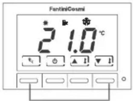
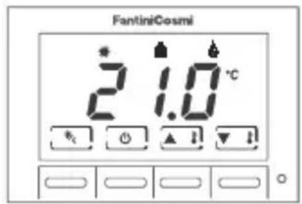
Press both keys simultaneously to select SUMMER (cooling) or WINTER (heating) mode.
6 THERMOSTAT CONFIGURATION
ATTENTION: only qualified personnel may configure the device.
Configuring the thermostat allows you to customise the device's operating parameters. Perform the following steps to access the configuration program:
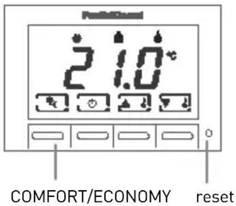
1 Using a sharp object, press the reset button while holding down the "COMFORT/ECONOMY" button at the same time.
2 When the display reads P01, release the "COMFORT/ECONOMY" button.
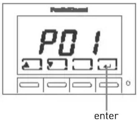
The display represents the configuration parameters by an index: P01, P02....
Press ▲ or ▼ to scroll the parameter indexes.
Press ← to edit a parameter. Use ▲ and ▼ to change the value of the parameter. Press again to go back to the parameter index.
To exit parameter configuration, press ▲ or ▼ until the display reads "END". Press ←.
CH121
Index Parameter Default Values
| P01 display mode 1 1 = view room temp | |
| 2 = view set point | |
| P02 correction of displayed temperature value | 0.0°C +/- 4°C (step 0.1°C) |
| P03 winter lower limit set point temperature | 2.0°C 2.0°C......40.0°C (step 1.0°C) |
| P04 winter upper limit set point temperature | 40.0°C 2.0°C......40.0°C (step 1.0°C) |
| P05 summer lower limit set point temperature | 2.0°C 2.0°C......40.0°C (step 1.0°C) |
| P06 summer upper limit set point temperature | 40.0°C 2.0°C......40.0°C (step 1.0°C) |
| P07 differential adjustment 0.3°C ±0.3°C......±2.0°C * (step 0.1°C) | |
| P08 temperature scale CEL CEL = Celsius | |
| FAH = Fahrenheit | |
| END exit parameter configuration and store values | |
* ± 0.3°C value suited for plants with slow thermal inertia, ± 2°C value suited for very reactivate plants.
7 TECHNICAL FEATURES
Power supply 2 AAA 1.5V batteries
Battery duration approximately 1 year *
Contact range 5(3)A 250V\~
voltage-free switching
Maximum room temperature T45 °C
Temperature adjustment scale 2 ÷ 40^ , increase 0.1^
Measurement scale/room T display -40 ÷ 50 °C
Type of action micro disconnection1B
Degree of protection IP20
Pollution degree 2
Pulse voltage 4000V
Electric insulation

Software Class A
Thermal gradient of reference 4K/h
Assembly recessed in 3-module box type 503, with 2 screws
Dimensions 68 x 52.2 x 58 mm
Product not made in Italy
Compliance with standards
EN 60730-1 and second parts
ErP classification
ErP Class IV; 2% (Reg. EU811/2013-813/2013)
* N.B. the life of the batteries is greatly affected by the type of use and the settings made by the user, especially the set back lighting switch-on time.

natural_image
Symbol of a trash bin crossed with diagonal lines, no text or numbers presentWASTE DISPOSAL
The symbol of the crossed-out wheeled bin indicates that the products must be collected and disposed of separately from household waste. The batteries and integrated accumulators may be disposed of together with the product. They will be separated at the recycling facilities. A black bar indicates that the product was placed on the market after August 13th, 2005.
Participating in the separate collection of products and batteries contributes to the correct disposal of these materials and therefore avoids possible negative consequences for the environment and human health. For more detailed information on the collection and recycling programmes available in your country, contact the local authorities or the sales point where you purchased the product.

FANTINI COSMI S.p.A.
Brand : Fantini Cosmi
Model : CH121
Category : Thermostat