
CR230216G002 - Air conditioner Hoffman - Free user manual and instructions
Find the device manual for free CR230216G002 Hoffman in PDF.


| Product Type | Air Conditioner (Split System) |
| Model | CR230216G002 |
| Brand | Hoffman |
| Cooling Capacity | 12000 BTU/h |
| Heating Capacity | 13000 BTU/h (Heat Pump) |
| Energy Efficiency Ratio (EER) | 3.5 (Class A) |
| Power Supply | 220-240 V, 50 Hz, 1 Phase |
| Rated Power Consumption (Cooling) | 1050 W |
| Indoor Unit Dimensions (W x H x D) | 770 x 280 x 210 mm |
| Outdoor Unit Dimensions (W x H x D) | 700 x 550 x 250 mm |
| Indoor Unit Weight | 10 kg |
| Outdoor Unit Weight | 25 kg |
| Refrigerant Type | R32 |
| Air Flow Rate | 400 m³/h (High) |
| Noise Level (Indoor) | 28 dB(A) (Low) - 40 dB(A) (High) |
| Noise Level (Outdoor) | 52 dB(A) |
| Thermostat Control | Remote Control with LCD Display |
| Modes | Cool, Heat, Dry, Fan, Auto |
| Timer Function | 24-Hour On/Off Timer |
| Filter Type | Washable Pre-Filter (every 2 weeks) |
| Maintenance | Clean filter with water; annual professional check |
| Safety Features | Auto-restart, Overheat Protection, Child Lock |
| Spare Parts Availability | Remote control, filters, fan motor (contact service center) |
Frequently Asked Questions - CR230216G002 Hoffman
User questions about CR230216G002 Hoffman
0 question about this device. Answer the ones you know or ask your own.
Ask a new question about this device
Download the instructions for your Air conditioner in PDF format for free! Find your manual CR230216G002 - Hoffman and take your electronic device back in hand. On this page are published all the documents necessary for the use of your device. CR230216G002 by Hoffman.
USER MANUAL CR230216G002 Hoffman
natural_image
Exterior view of a stainless steel industrial control cabinet with ventilation grilles (no visible text or symbols)PROAIR
AIR CONDITIONER
CR23 MODEL
INSTRUCTION MANUAL
DESIGN WITH CONFIDENCE
TABLE OF CONTENTS
RECEIVING THE AIR CONDITIONER 3
HANDLING AND TESTING THE AIR CONDITIONER 3
INSTALLATION INSTRUCTIONS 4
SYSTEM CONTROLS 4
Level I Temperature Controller 4
Level II and III Temperature Controller 4
TECHNICAL INFORMATION....5
DESIGN DATA 5
DIMENSION DRAWING 5
Mounting Gasket Kit 6
Design Notes 6
Mounting Cutout Dimensions....6
Components List....7
Optional Parts 7
Parts List....7
Wire Diagrams and Schematics 8
Wire Diagram, Level I....8
Wire Diagram, Level I with Electric Heater 9
Wire Diagram, Level II and III 10
Wire Diagram, Level II and III with Electric Heater 12
TEMPERATURE CONTROL 14
PRINCIPLES OF OPERATION 14
MAINTENANCE....14
Compressor 14
Inlet Air Filter 14
How To Remove, Clean or Install a New Inlet Air Filter 15
Condenser and Evaporator Air Movers 15
Refrigerant Loss 15
TROUBLE SHOOTING....16
Basic Air Conditioning Trouble Shooting Check List.... 16
Symptoms and Possible Causes: 17
WARRANTY 18
RETURN AND REPAIR POLICY....18
LIMITATION OF LIABILITY....19
RECEIVING THE AIR CONDITIONER
Inspect the air conditioner. Check for concealed damage that may have occurred during shipment. Look for dents, scratches, loose assemblies, evidence of oil, etc. Damage evident upon receipt should be noted on the freight bill. Damage should be brought to the attention of the delivering carrier -- NOT to Pentair Equipment Protection -- within 15 days of delivery. Save the carton and packing material and request an inspection. Then file a claim with the delivering carrier.
Pentair Equipment Protection cannot accept responsibility for freight damages; however, we will assist you in any way possible.
HANDLING AND TESTING THE AIR CONDITIONER
If the air conditioner has been in a horizontal position, be certain it is placed in an upright, vertical or mounting position for a minimum of five (5) minutes before operating.

CAUTION
Do not attempt to operate the air conditioner while it is horizontal or on its side, back or front. The refrigeration compressor is filled with lubricating oil. This will cause permanent damage to the air conditioner and also voids the warranty.
TEST FOR FUNCTIONALITY BEFORE MOUNTING THE AIR CONDITIONER TO THE ENCLOSURE.
Refer to the nameplate for proper electrical current requirements, and then connect the power cord to a properly grounded power supply. Minimum circuit ampacity should be at least 125% of the amperage shown in the design data section for the appropriate model. No other equipment should be connected to this circuit to prevent overloading.
Operate the air conditioner for five (5) to ten (10) minutes. No excessive noise or vibration should be evident during this run period. The condenser blower (ambient air), the evaporator blower (enclosure air), and the compressor should be running.
Condenser air temperatures should be warmer than normal room temperatures within a few minutes.
The compressor is provided with automatic reset thermal overload protection. This thermo-switch is located and mounted inside the plastic enclosure clipped to the compressor. The switch operates when the compressor overheats due to clogged or dirty inlet air filter or if ambient air temperatures exceed nameplate rating or if enclosure dissipated heat loads exceed the rated capacity of the air conditioner. The thermal overload switch will actuate and stop compressor operation. The blowers will continue to operate and the compressor will restart after it has cooled to within the thermal overload cut-in temperature setting.
INSTALLATION INSTRUCTIONS
- Inspect air conditioner and verify functionality before mounting the air conditioner, see HANDLING AND TESTING THE AIR CONDITIONER on page 3.
- Using the cutout dimensions shown in this manual, prepare the air "IN" and air "OUT" openings, and mounting bolt hole pattern for the enclosure.
- Using the gasket kit provided, install gaskets to air conditioner. See Mounting Gasket Kit on page 6 for proper location.
- Mount air conditioner on enclosure using mounting bolts and washers provided to secure unit to enclosure. Allow unit to remain upright for a minimum of five (5) minutes before starting. Caution! Air conditioner must be in upright position during operation.
- Refer to the top of the nameplate for electrical requirements. Connect the power cord to a properly grounded power supply. Use of an extension cord is not recommended. Electrical circuit should be fused with slow blow or HACR circuit breaker.
- When the unit is equipped with an automatic temperature controller, the controller is preset at the factory for your convenience and should not require adjustment.
SYSTEM CONTROLS
The Level I controller is located inside the air conditioner. To adjust, disconnect power to the air conditioner. Open the front panel by loosening the front panel screw. Refer to Figure 2 on page 7 to locate the controller. Turn the controller adjustment screw slot counter-clockwise to increase and clockwise to decrease the temperature set point, see Figure 1. The thermostat cooling setpoint is indicated by the alignment of the adjustment screw slot with the dial decal. After completing adjustment, close the front panel and tighten the front panel screw. Restore power to the air conditioner for operation.
LEVEL II AND III TEMPERATURE CONTROLLER
The Level II and III controller is mounted on the air conditioner front panel and is factory set for standard operation. All operating parameters are programmable for custom applications. Refer to the Level II and III programming and Operating Instruction Manual, 10-1008-161.
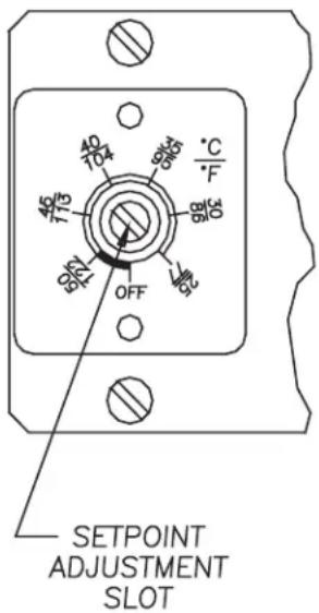
Figure 1
TECHNICAL INFORMATION
DESIGN DATA
| Model Voltage Hz Phase | BTU/Hr @ 131 F/131 F | Amps @ 131 F/131 F | BTU/Hr @ 95 F/95 F | Amps @ 95 F/95 F | Max Amb Temp °F/°C | Shipping Weight lb./kg |
| CR230216GXXX 115 50/60 1 1600/1600 4.1/4.0 1400/1500 3.7/3.1 131/55 57/26 | ||||||
| CR230226GXXX 230 50/60 1 1500/1600 2.7/2.5 1400/1400 2.0/2.0 131/55 57/26 | ||||||
CR230216GXXX 115 50/60 1 1600/1600 4.1/4.0 1400/1500 3.7/3.1 131/55 57/26
-XXX will be replaced with a three-digit number designating all desired options. Consult the factory for specific model numbers.
DIMENSION DRAWING
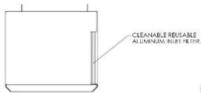
TOP VIEW
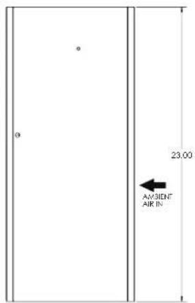
FRONT VIEW
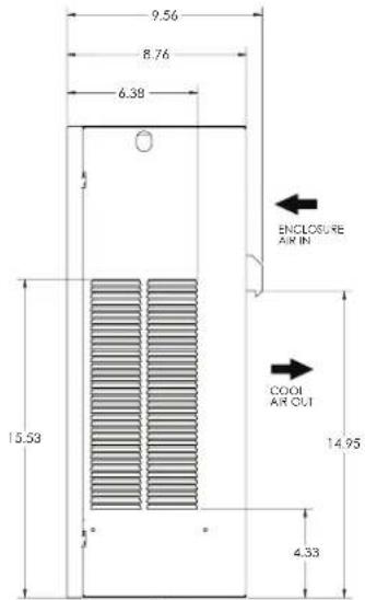
AMBIENT AIR OUT
SIDE VIEW
![10.00 9.39 (4) .65 (4) 7/4.20 UNC [8] 21.70 (2) 18.45 (2) 15.20 (2) 4.45 (2) 5.92 6.58 (167) SEE NOTE 2](/content/2026/05/784502/images/1bfe2d82ed35f014c0cb55ff74245fdc3f8ac7f71d691442cf369a49c090659f.jpg)
BACK VIEW
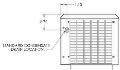
BOTTOM VIEW
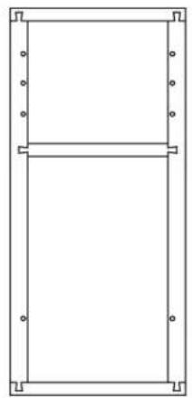
MOUNTING GASKET KIT
DESIGN NOTES
- Gasket kit included. Apply gasket to rear of air conditioner before mounting on enclosure.
- Service cord terminated with appropriate plug cap.
- Millimeter dimensions [ ] are for reference only; do not convert to inch dimensions.
- Allow at least 4 inch inlet and 6 inch outlet clearance for proper ambient air flow. Allow 20 inch above filter for removal.
Mounting gasket kit part no. 23-2000-00 as applied to rear of CR23.
natural_image
Pure architectural line drawing of a rectangular frame with corner brackets and corner holes (no text or symbols)MOUNTING CUTOUT DIMENSIONS
![10.00 [254] 9.38 (4X) [238] 9.00 (2X) [229] 1.00 (2X) [25] .64 (4X) [16] 1.30 [33] (3X) 8.80 [224] 8.05 [204] 17.80 [452] 23.00 [584] Ø .28 [7] (6X) 4.55 [116] (2X) 7.80 [198] (2X) 18.55 [471] (2X) 87963730 AC OUTLINE](/content/2026/05/784502/images/c4309a747e1692d19e2db0a0a1f3afda87b71a7e63a5f8d5fa21bd8acde82180.jpg)
Dashed lines represent the outline of the air conditioner.
COMPONENTS LIST
| Part Description 115 Volt 230 Volt | ||
| Blower, Condenser 12-1012-01 12-1012-02 | ||
| Blower, Evaporator 12-1012-01 12-1012-02 | ||
| Capacitor, Compressor, Start/Run N/A N/A | ||
| Compressor 89109065 89109066 | ||
| Thermal Overload, Compressor 10-1007-19 | 10-1007-58 | |
| Filter, Air, Reusable 23-2004-00 23-2004-00 | ||
| Thermostat, SPST, 55-100F 10-1061-16 10- | 1061-16 | |
| Mounting Gasket Kit 23-2000-00 23-2000-00 | ||
| Relay, Compressor | N/A N/A | |
| Power Cord | 52-6035-15 52-6035-74 |
OPTIONAL PARTS
| Part Description 115 Volt 230 Volt | ||
| Electric Heat Element | 10-1038-40 10-1038-43 | |
| Electric Heat Limit Switch | 10-1033-01 10-1033-01 | |
| Level II/III Transformer | 10-1006-94 10-1006-93 | |
PARTS LIST
| Part | Description | Part No. |
| 1 | Condenser Coil | 23-2001-00 |
| 2 | Fan Pan | 23-2003-00 |
| 3 | Condenser Blower | See Components List |
| 4 | Evaporator Coil | 23-2002-00 |
| 5 | Air Filter | 23-2004-00 |
| 6 | Compressor | See Components List |
| 7 | Cool Relay(Lev. II/III only) | 10-1005-21 |
| 8 | Transformer(Lev. II/III only) | See Optional Parts |
| 9 | Heat Relay(Lev. II/III with Electric Heat only) | 10-1005-21 |
| 10 | Temperature Controller | Consult Factory |
| 11 | Electric Heat Element and Limit Switch | See Optional Parts |
| 12 | Terminal Block | 10-1003-03 |
| 13 | Expansion Valve | Consult Factory |
| 14 | Evaporator Blower | See Components List |
| 15 | Filter Drier | 52-6028-03 |
| 16 | Compressor Thermal Overload | See Components List |
| 17 | Mounting Gasket Kit | 23-2000-00 |
| 18 | Power Cord | See Components List |
| 19 | Capillary Tube | 99-0360-60 |
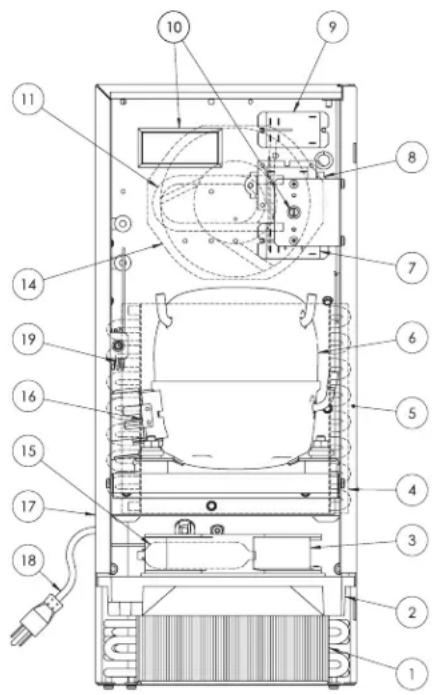
Figure 2
WIRE DIAGRAMS AND SCHEMATICS
WIRE DIAGRAM, LEVEL I
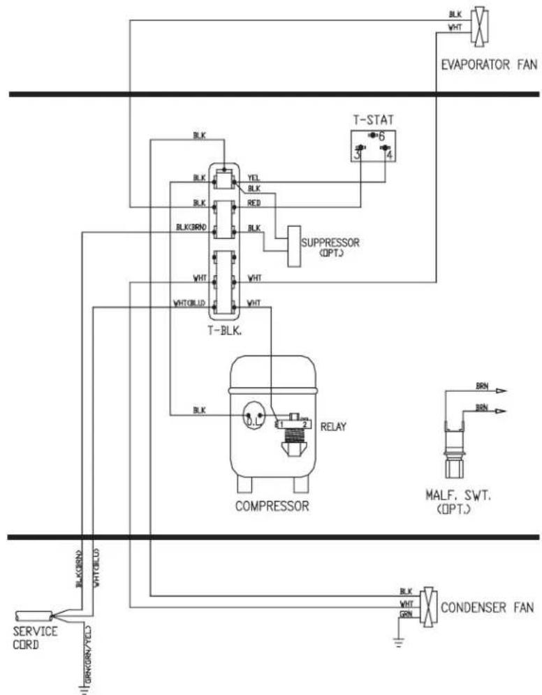
flowchart
graph TD
    A["EVAPORATOR FAN"] --> B["T-STAT"]
    B --> C["BLK"]
    B --> D["BLK"]
    B --> E["BLK"]
    B --> F["BLK"]
    B --> G["BLK"]
    B --> H["BLK"]
    B --> I["SUPPRESSOR (OPT)"]
    I --> J["T-BLK."]
    J --> K["BLK"]
    J --> L["BLK"]
    J --> M["RELAY"]
    M --> N["COMPRESSOR"]
    N --> O["MALF, SWT. (OPT.)"]
    O --> P["BRN"]
    O --> Q["BRN"]
    O --> R["BRN"]
    O --> S["BRN"]
    O --> T["BRN"]
    U["SERVICE CORD"] --> V["BLKND"]
    V --> W["VHTOLED"]
    X["BRKNV/YELD"] --> Y["BRKNV/YELD"]
    Z["BLK"] --> AA["YEL"]
    AB["BLK"] --> AC["RED"]
    AD["VHT"] --> AE["VHT"]
    AF["VHTOLED"] --> AG["VHT"]
    AH["T-BLK."] --> AI["BLK"]
    AJ["BLK"] --> AK["BLK"]
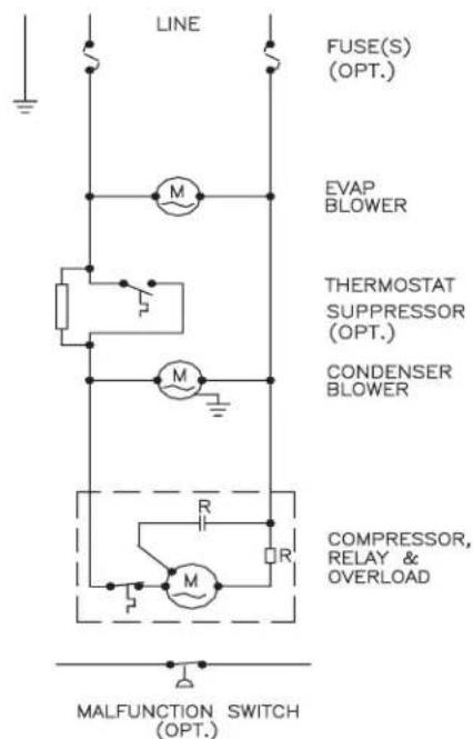
ELECTRICAL SCHEMATIC
WIRE DIAGRAM, LEVEL I WITH ELECTRIC HEATER
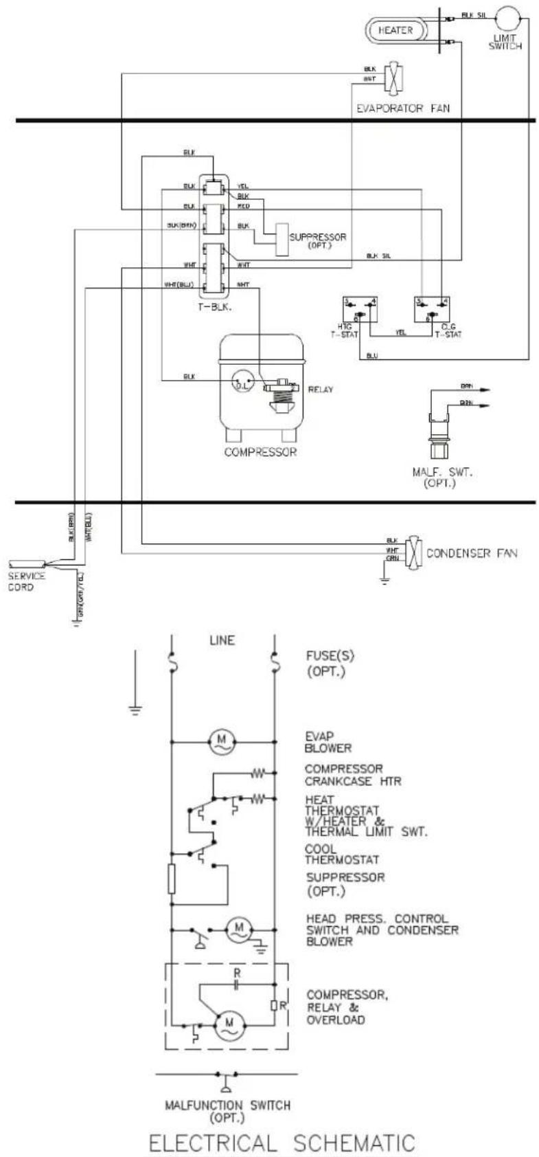
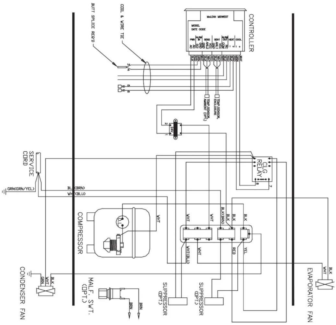
NOTE: For voltage, hertz, and options not shown in this manual, refer to the wiring diagram attached to the unit.
WIRE DIAGRAM, LEVEL II AND III
flowchart
graph TD
    A["CONDENSER FAN"] --> B["BLK"]
    B --> C["HVIT"]
    C --> D["Water Splitter"]
    D --> E["COMPRESSOR"]
    E --> F["BLK"]
    F --> G["HVIT"]
    G --> H["HVIT"]
    H --> I["BLK"]
    I --> J["HVIT"]
    J --> K["BLK"]
    K --> L["BLK"]
    L --> M["BLK"]
    M --> N["BLK"]
    N --> O["BLK"]
    O --> P["BLK"]
    P --> Q["BLK"]
    Q --> R["BLK"]
    R --> S["BLK"]
    S --> T["BLK"]
    T --> U["BLK"]
    U --> V["BLK"]
    V --> W["BLK"]
    W --> X["BLK"]
    X --> Y["BLK"]
    Y --> Z["BLK"]
    Z --> AA["BLK"]
    AA --> AB["BLK"]
    AB --> AC["BLK"]
    AC --> AD["BLK"]
    AD --> AE["BLK"]
    AE --> AF["BLK"]
    AF --> AG["BLK"]
    AG --> AH["BLK"]
    AH --> AI["BLK"]
    AI --> AJ["BLK"]
    AJ --> AK["BLK"]
    AK --> AL["BLK"]
    AL --> AM["BLK"]
    AM --> AN["BLK"]
    AN --> AO["BLK"]
    AO --> AP["BLK"]
    AP --> AQ["BLK"]
    AQ --> AR["BLK"]
    AR --> AS["BLK"]
    AS --> AT["BLK"]
    AT --> AU["BLK"]
    AU --> AV["BLK"]
    AV --> AW["BLK"]
    AW --> AX["BLK"]
    AX --> AY["BLK"]
    AY --> AZ["BLK"]
    AZ --> BA["BLK"]
    BA --> BB["BLK"]
    BB --> BC["BLK"]
    BC --> BD["BLK"]
    BD --> BE["BLK"]
    BE --> BF["BLK"]
    BF --> BG["BLK"]
    BG --> BH["BLK"]
    BH --> BI["BLK"]
    BI --> BJ["BLK"]
    BJ --> BK["BLK"]
    BK --> BL["BLK"]
    BL --> BM["BLK"]
    BM --> BN["BLK"]
    BN --> BO["BLK"]
    BO --> BP["BLK"]
    BP --> BQ["BLK"]
    BQ --> BR["BLK"]
    BR --> BS["BLK"]
    BS --> BT["BLK"]
    BT --> BU["BLK"]
    BU --> BV["BLK"]
    BV --> BW["BLK"]
    BW --> BX["BLK"]
    BX --> BY["BLK"]
    BY --> BZ["BLK"]
    BZ --> CA["BLK"]
    CA --> CB["BLK"]
    CB --> CC["BLK"]
    CC --> CD["BLK"]
    CD --> CE["BLK"]
    CE --> CF["BLK"]
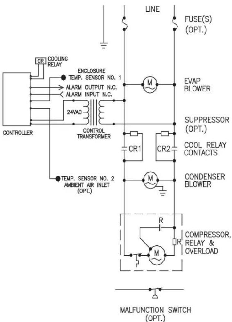
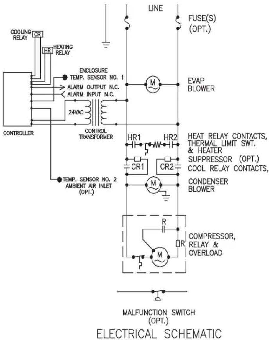
ELECTRICAL SCHEMATIC
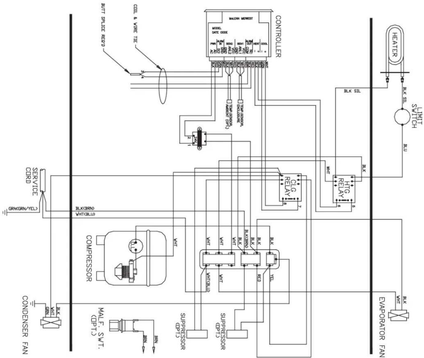
WIRE DIAGRAM, LEVEL II AND III WITH ELECTRIC HEATER
flowchart
graph TD
    A["Controller"] -->|BLK SIL| B["Heater"]
    A -->|BLK SIL| C["Evaporator Fan"]
    A -->|BLK SIL| D["BLU"]
    A -->|BLK SIL| E["LIMIT SWITCH"]
    A -->|BLK SIL| F["BLU"]
    A -->|BLK SIL| G["BLU"]
    A -->|BLK SIL| H["BLU"]
    A -->|BLK SIL| I["BLU"]
    A -->|BLK SIL| J["BLU"]
    A -->|BLK SIL| K["BLU"]
    A -->|BLK SIL| L["BLU"]
    A -->|BLK SIL| M["BLU"]
    A -->|BLK SIL| N["BLU"]
    A -->|BLK SIL| O["BLU"]
    A -->|BLK SIL| P["BLU"]
    A -->|BLK SIL| Q["BLU"]
    A -->|BLK SIL| R["BLU"]
    A -->|BLK SIL| S["BLU"]
    A -->|BLK SIL| T["BLU"]
    A -->|BLK SIL| U["BLU"]
    A -->|BLK SIL| V["BLU"]
    A -->|BLK SIL| W["BLU"]
    A -->|BLK SIL| X["BLU"]
    A -->|BLK SIL| Y["BLU"]
    A -->|BLK SIL| Z["BLU"]
    A -->|BLK SIL| AA["BLU"]
    A -->|BLK SIL| AB["BLU"]
    A -->|BLK SIL| AC["BLU"]
    A -->|BLK SIL| AD["BLU"]
    A -->|BLK SIL| AE["BLU"]
    A -->|BLK SIL| AF["BLU"]
    A -->|BLK SIL| AG["BLU"]
    A -->|BLK SIL| AH["BLU"]
    A -->|BLK SIL| AI["BLU"]
    A -->|BLK SIL| AJ["BLU"]
    A -->|BLK SIL| AK["BLU"]
    A -->|BLK SIL| AL["BLU"]
    A -->|BLK SIL| AM["BLU"]
    A -->|BLK SIL| AN["BLU"]
    A -->|BLK SIL| AO["BLU"]
    A -->|BLK SIL| AP["BLU"]
    A -->|BLK SIL| AQ["BLU"]
    A -->|BLK SIL| AR["BLU"]
    A -->|BLK SIL| AS["BLU"]
    A -->|BLK SIL| AT["BLU"]
    A -->|BLK SIL| AU["BLU"]
    A -->|BLK SIL| AV["BLU"]
    A -->|BLK SIL| AW["BLU"]
    A -->|BLK SIL| AX["BLU"]
    A -->|BLK SIL| AY["BLU"]
    A -->|BLK SIL| AZ["BLU"]
    A -->|BLK SIL| BA["BLU"]
    A -->|BLK SIL| BB["BLU"]
    A -->|BLK SIL| BC["BLU"]
    A -->|BLK SIL| BD["BLU"]
    A -->|BLK SIL| BE["BLU"]
    A -->|BLK SIL| BF["BLU"]
    A -->|BLK SIL| BG["BLU"]
    A -->|BLK SIL| BH["BLU"]
    A -->|BLK SIL| BI["BLU"]
    A -->|BLK SIL| BJ["BLU"]
    A -->|BLK SIL| BK["BLU"]
    A -->|BLK SIL| BL["BLU"]
    A -->|BLK SIL| BM["BLU"]
    A -->|BLK SIL| BN["BLU"]
    A -->|BLK SIL| BO["BLU"]
    A -->|BLK SIL| BP["BLU"]
    A -->|BLK SIL| BQ["BLU"]
    A -->|BLK SIL| BR["BLU"]
    A -->|BLK SIL| BS["BLU"]
    A -->|BLK SIL| BT["BLU"]
    A -->|BLK SIL| BU["BLU"]
    A -->|BLK SIL| BV["BLU"]
    A -->|BLK SIL| BW["BLU"]
    A -->|BLK SIL| BX["BLU"]
    A -->|BLK SIL| BY["BLU"]
    A -->|BLK SIL| BZ["BLU"]
    A -->|BLK SIL| CA["BLU"]
    A -->|BLK SIL| CB["BLU"]
    A -->|BLK SIL| CC["BLU"]
    A -->|BLK SIL| CD["BLU"]
    A -->|BLK SIL| CE["BLU"]
    A -->|BLK SIL| CF["BLU"]
    A -->|BLK SIL| CG["BLU"]
    A -->|BLK SIL| CH["BLU"]
    A -->|BLK SIL| CI["BLU"]
    A -->|BLK SIL| CJ["BLU"]
    A -->|BLK SIL| CK["BLU"]
NOTE: For voltage, hertz, and options not shown in this manual, refer to the wiring diagram attached to the unit.
TEMPERATURE CONTROL
The electromechanical thermostat is factory preset to 75 F/23 C. To change the temperature setting, remove the nylon plug from the back face of the unit. Use a standard screwdriver to adjust thermostat. For cooler temperatures turn clockwise, for warmer temperatures turn counterclockwise.
PRINCIPLES OF OPERATION
If electrical power to the air conditioner is interrupted and reapplied immediately (within 3 to 5 seconds), the compressor may not restart due to the high back pressure of the compressor. It takes a minimum of one (1) minute after shut-down for the compressor suction and discharge pressures to equalize in order for the air conditioner to restart.
Operating the air conditioner below the minimum ambient temperature or above the maximum ambient temperatures indicated on the nameplate voids all warranties.
It is recommended that the warranty section of this manual be read in order to familiarize yourself with parameters of restricted operation.
The moisture that the enclosure air can contain is limited. If moisture flows from the drain tube continuously this can only mean that ambient air is entering the enclosure. Be aware that frequent opening of the enclosure's door admits humid air which the air conditioner must then dehumidify.
MAINTENANCE
COMPRESSOR
The compressor requires no maintenance. It is hermetically sealed, properly lubricated at the factory and should provide years of satisfactory operating service.
Should the refrigerant charge be lost, recharging ports (access fittings) on the suction and discharge sides of the compressor are provided for recharging and/or checking suction and discharge pressures.
Under no circumstances should the access fitting covers be loosened, removed or tampered with.
Breaking of seals on compressor access fittings during warranty period will void warranty on hermetic system.
Recharging ports are provided for the ease and convenience of reputable refrigeration repair service personnel for recharging the air conditioner.
INLET AIR FILTER
Proper maintenance of the inlet air filter, located behind the front cover, will assure normal operation of the air conditioner. If filter maintenance is delayed or ignored, the maximum ambient temperatures under which the unit is designed to operate will be decreased.
If the compressor's operating temperature increases above designed conditions due to a dirty or clogged filter (or plugged condenser coil), the air conditioner's compressor will stop operating due to actuation of the thermal overload cut-out switch located on the compressor housing. As soon as the compressor temperature has dropped to within the switch's cut-in setting, the compressor will restart automatically. However the above condition will continue to take place until the filter or coil has been cleaned. It is recommended that power to the air conditioner be interrupted intentionally when abnormally high compressor operating temperature causes automatic shutdown of the unit.
The above described shut-down is symptomatic of a clogged or dirty filter, thus causing a reduction in cooling air flow across the surface of the compressor and condenser coil.
Do not run the air conditioner for extended periods of time with the filter removed. Particles of dust, lint, etc., can plug the fins of the condenser coil which will give the same reaction as a plugged filter. The condenser coil is not visible through the filter opening, so protect it with a filter.
Continued operation under the above conditions can and will damage and shorten compressor life. The air conditioner is available with an easily removable inlet filter to facilitate necessary cleaning. There should be no reason to neglect this necessary maintenance.
HOW TO REMOVE, CLEAN OR INSTALL A NEW INLET AIR FILTER
RP aluminum washable air filters are designed to provide excellent filtering efficiency with a high dust holding capacity and a minimum amount of resistance to air flow. Since they are constructed entirely of aluminum, they are lightweight and easy to service. Optimum filter performance is maintained by recoating the filters after washing with RP Super Filter Coat adhesive. To achieve maximum performance from your air handling equipment, air filters should be cleaned on a regular basis.
The inlet air filter is located behind the right side panel. To access the filter, pull from slot on top cover. The filter may now be cleaned or a new filter installed.
Cleaning Instructions:
- Flush the filter with warm water from the exhaust side to the intake side. DO NOT USE CAUSTICS.
- After flushing, allow filter to drain. Placing it with a corner down will assure complete drainage.
- Recoat the filters with RP Super Filter Coat adhesive. When spraying filter do so from both sides for maximum concentration of adhesive.
CONDENSER AND EVAPORATOR AIR MOVERS
Fan motor requires no maintenance. All bearings, shafts, etc. are lubricated for the life of the motor during manufacturing.
If the condenser fan motor (ambient fan) should fail, it is not necessary to remove the air conditioner from the cabinet or enclosure to replace the fan. The condenser fan is mounted on its own bulkhead and is easily accessible by opening the front cover.

CAUTION
Operation of the air conditioner in areas containing airborne caustics or chemicals can rapidly deteriorate filters, condenser coils, blowers and motors, etc. Contact Pentair Equipment Protection for special recommendations.
REFRIGERANT LOSS
Each air conditioner is thoroughly tested prior to leaving the factory to insure against refrigeration leaks. Shipping damage or microscopic leaks not found with sensitive electronic refrigerant leak detection equipment during manufacture may require repair or recharging of the system. This work should only be performed by qualified professionals, generally available through a local, reputable air conditioning repair or service company.
Refer to the data on the nameplate which specifies the type of refrigerant and the charge size in ounces.
Before recharging, make sure there are no leaks and that the system has been properly evacuated into a deep vacuum.
TROUBLE SHOOTING
BASIC AIR CONDITIONING TROUBLE SHOOTING CHECK LIST
- Check manufacturer's nameplate located on the unit for correct power supply.
- Turn on power to the unit. The evaporator (Enclosure or "COLD" air) fan should come on. Is there airflow?
YES, proceed to step 3.
NO, possible problem:
- Open motor winding
- Stuck fan motor
- Obstructed blades
Repair or Replace defective part
- Check thermostat setting and adjust thermostat to the lowest setting. This should turn on the condenser fan and compressor. Did condenser fan and compressor come on when the thermostat was turned on?
YES, proceed to step 4.
NO, possible problem:
• Defective thermostat
- Are both fans and the compressor running? If not, the unit will not cool properly.
- Check condenser (Ambient or "HOT" air) fan for airflow. Is there airflow?
YES, proceed to step 6.
NO, possible problem:
• Defective thermostat
- Open motor winding
- Stuck fan motor
- Obstructed blades
Repair or Replace defective part
- Carefully check the compressor for operation - motor should cause slight vibration, and the outer case of the compressor should be warm. Is the compressor showing signs of this?
YES, wait 5 minutes, then proceed to step 7.
NO, possible problem:
• Defective thermostat
• Defective capacitor
• Defective overload
- Defective relay
Repair or Replace defective part
- Make sure the coils are clean. Then check evaporator "air in" and "air out" temperatures. If the temperatures are the same:
• Possible loss of refrigerant
• Possible bad valves in the compressor
Repair or Replace defective part
- To check for a bad thermostat, turn power off to the unit. Remove control box cover and place both thermostat wires onto one terminal (replace control box cover for safety). This will bypass the switch in the thermostat. Turn on the power. If both fans and the compressor come on, the thermostat needs to be replaced.
SYMPTOMS AND POSSIBLE CAUSES:
| SYMPTOM POSSIBLE CAUSE | |
| Unit won't cool | Fans not running |
| Compressor not running | |
| Compressor runs, but has bad valves | |
| Loss of refrigerant | |
| Compressor tries to start but won't run | Low line voltage at start. Should be +/-10% rated voltage. |
| Compressor motor stuck | |
| Bad relay | |
| Bad overload switch | |
| Bad run/start capacitor | |
| Unit blows breakers | Undersized breaker/fuse or not time delayed |
| Short in system | |
| Getting water in enclosure | Drain plugged |
| Drain tube kinked | |
| Enclosure not sealed (allowing humidity in) | |
For additional technical support (amp draw, pressures, temperatures), contact Pentair Equipment Protection at 800-896-2665.
WARRANTY
Pentair Equipment Protection warrants that the Goods manufactured by Pentair Equipment Protection will be free from defects in material and workmanship for a period of one (1) year from the date of shipment by Pentair Equipment Protection, subject to the following conditions and exclusions:
A. Conditions. All Goods must be installed and operated according to the following specifications:
- Maximum voltage variation no greater than plus or minus 10% of nameplate nominal rating;
- Maximum frequency variation no greater than plus or minus 3 Hz of nameplate nominal rating;
- Must not exceed minimum and maximum stated temperatures on the nameplate;
- Must not exceed (BTU/Hr) rating, including any heat sink as indicated on the nameplate;
- Refrigerant bearing Goods must not be restarted for a period of one (1) minute after intentional or accidental shut-off;
- The filters (if applicable) must be cleaned regularly;
- The Goods and any parts thereof must not be modified, unless prior written authorization is received from Pentair Equipment Protection; and
- All Goods must be installed and grounded in accordance with all relevant electrical and safety codes, as well as the National Electric Code and OSHA rules and regulations.
- All Goods must be installed in a stationery application, free of vibration.
A violation of any one of these conditions shall render the warranty hereunder void and of no effect.
B. Exclusions. This warranty shall be void if product is misapplied in any way or:
- Buyer specified product is inappropriate for system or environment in which it is operating.
- Goods are not installed in accordance with Pentair Equipment Protection specifications.
- Removal or modification of Pentair Equipment Protection label affixed to product without written Pentair Equipment Protection approval.
Pentair Equipment Protection must be notified of a claim in writing not later than fourteen (14) days from the date when Buyer has become aware of such occurrence, or where the defect is such that it may cause damage, immediately, such notice containing a description of how the defect manifests itself. Failure to provide such prompt notice to Pentair Equipment Protection shall result in forfeiture of Buyer's rights under this warranty.
In the event of a warranty claim, Buyer is to return defective goods to Pentair Equipment Protection in accordance with Pentair Equipment Protection Return Policy. Warranty period for repaired goods remains at 1 year from shipment of original goods. Pentair Equipment Protection sole obligation to Buyer under this warranty will be, at Pentair Equipment Protection option:
A. Repair or replace Pentair Equipment Protection products or parts found to be defective in material or workmanship.
B. Issue credit for the purchase price paid by Buyer relating to such defective Goods or part.
THIS WARRANTY CONSTITUTES THE ENTIRE WARRANTY WITH RESPECT TO THE GOODS AND IS IN LIEU OF ALL OTHER WARRANTIES, EXPRESSED OR IMPLIED, INCLUDING ANY IMPLIED WARRANTY OF MERCHANTABILITY AND IMPLIED WARRANTY OF FITNESS FOR A PARTICULAR PURPOSE.
RETURN AND REPAIR POLICY
Pentair Equipment Protection products that: (i) are made to order, (ii) have been modified by Buyer, (iii) have special finishes, or (iv) are determined by Pentair Equipment Protection to constitute “custom” products that cannot be returned to stock or resold to other Buyers, will not be accepted for return by Pentair Equipment Protection.
All returns require a Return Material Authorization number (RMA #), regardless of reason for return, whether it be for warranty or out of warranty repair. Returns without an RMA # will be refused by our Receiving Department. An RMA # is valid for 30 days.
A. An RMA # will be issued by our Product Return Department in Anoka, MN at 763-422-2211. Buyer should have following information available at time of RMA request:
- Complete Model Number, Serial Number and description of damaged unit being returned.
- Original Buyer Purchase Order number and date product was received by Buyer.
- Quantity to be returned and a brief description of failure for each unit, if different.
- Contact information of Buyer that must include: name of company, billing and shipping address, phone, number, fax number, freight carrier and the name and phone number of a Buyer contact who can elaborate on the claimed defect in detail.
- Buyer must provide a Repair Purchase Order number for both warranty and out of warranty repairs. The PO will not exceed 50% of a new unit. Buyer will be notified of repair charges that exceed approved PO amount.
B. All returns to Pentair Equipment Protection must be securely packed, using original cartons if possible. All returns must have the RMA number visible on the outside of the carton. Pentair Equipment Protection is not responsible for material damaged in transit. Any refrigerant-bearing Goods must be shipped upright for return.
C. Shipping cost for all non-warranty repairs is the responsibility of the sender and must be shipped prepaid. Shipping costs for all warranty related repairs will be covered by Pentair Equipment Protection provided the goods are returned using a Pentair Equipment Protection approved carrier. If after diagnoses the product is determined by Pentair Equipment Protection not be covered under warranty, Buyer will be responsible for all shipping charges and will be billed accordingly.
D. Non-warranty repairs are subject to a \$105 minimum analysis fee. If approval is not received within 30 days, material will be scrapped and all shipping expenses and corresponding analysis fees will be billed to Buyer.
E. At Buyer's request, Failure Analysis can be provided by Pentair Equipment Protection for warrantable goods at no charge. Failure analysis for non-warranty repairs are subject to a \$150 per hour Engineering charge plus any other incurred testing costs.
F. All returned merchandise must be sent to the following address: Pentair Equipment Protection, 2100 Hoffman Way, Anoka, MN 55303-1745.
G. Credit for accepted returns shall be at the original selling price or the current selling price, whichever is lower, less the restocking charge indicated as follows:
- Within 60 days of invoice date - 20% of applicable selling price.
- Within 61-120 days of invoice date - 30% of applicable selling price.
- Within 121-180 days of invoice date - 40% of applicable selling price.
- Beyond 180 days - subject to individual review by Pentair Equipment Protection.
If product being returned for credit requires repair or modification, the cost of any labor or material necessary to bring product into saleable condition will be deducted from credit. Buyer may not take credit against returns without prior written Pentair Equipment Protection approval.
LIMITATION OF LIABILITY
PENTAIR EQUIPMENT PROTECTION WILL NOT BE LIABLE UNDER ANY CIRCUMSTANCES FOR ANY INCIDENTAL, CONSEQUENTIAL OR SPECIAL DAMAGES, INCLUDING WITHOUT LIMITATION ANY LOST PROFITS OR LABOR COSTS, ARISING FROM THE SALE, USE OR INSTALLATION OF THE GOODS, FROM THE GOODS BEING INCORPORATED INTO OR BECOMING A COMPONENT OF ANOTHER PRODUCT, FROM ANY BREACH OF THIS AGREEMENT OR FROM ANY OTHER CAUSE WHATSOEVER, WHETHER BASED ON WARRANTY (EXPRESSED OR IMPLIED) OR OTHERWISE BASED ON CONTRACT, OR ON TORT OR OTHER THEORY OF LIABILITY, AND REGARDLESS OF ANY ADVICE OR REPRESENTATIONS THAT MAY HAVE BEEN RENDERED BY PENTAIR EQUIPMENT PROTECTION CONCERNING THE SALE, USE OR INSTALLATION OF THE GOODS.
Pentair Equipment Protection
2100 Hoffman Way
Minneapolis, MN 55303 USA

+1.763.422.2211

+1.763.576.3200
PentairProtect.com
- PROAIR
- TABLE OF CONTENTS
- RECEIVING THE AIR CONDITIONER
- HANDLING AND TESTING THE AIR CONDITIONER
- CAUTION
- INSTALLATION INSTRUCTIONS
- SYSTEM CONTROLS
- LEVEL II AND III TEMPERATURE CONTROLLER
- TECHNICAL INFORMATION
- MOUNTING GASKET KIT
- DESIGN NOTES
- MOUNTING CUTOUT DIMENSIONS
- WIRE DIAGRAMS AND SCHEMATICS
- WIRE DIAGRAM, LEVEL II AND III
- WIRE DIAGRAM, LEVEL II AND III WITH ELECTRIC HEATER
- TEMPERATURE CONTROL
- PRINCIPLES OF OPERATION
- MAINTENANCE
- COMPRESSOR
- INLET AIR FILTER
- HOW TO REMOVE, CLEAN OR INSTALL A NEW INLET AIR FILTER
- CONDENSER AND EVAPORATOR AIR MOVERS
- REFRIGERANT LOSS
- TROUBLE SHOOTING
- BASIC AIR CONDITIONING TROUBLE SHOOTING CHECK LIST
- WARRANTY
- RETURN AND REPAIR POLICY
- LIMITATION OF LIABILITY
Brand : Hoffman
Model : CR230216G002
Category : Air conditioner