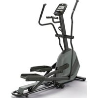
Torus - Fitness Equipment Horizon Fitness - Free user manual and instructions
Find the device manual for free Torus Horizon Fitness in PDF.


| Product Type | Fitness Treadmill |
| Brand | Horizon Fitness |
| Model | Torus |
| Dimensions (L x W x H) | 80 x 35 x 55 inches |
| Weight | 250 lbs |
| Motor Power | 3.0 CHP |
| Speed Range | 0.5 - 12 mph |
| Incline Range | 0% - 15% |
| Running Surface | 22 x 60 inches |
| Display Type | LCD with Blue Backlight |
| Workout Programs | 12 Preset Programs |
| Heart Rate Monitor | Pulse Grips and Chest Strap Compatible |
| Audio | Bluetooth Speakers, MP3 Input |
| Folding Design | Foldable with SoftDrop System |
| Maximum User Weight | 350 lbs |
| Power Requirements | 120V, 15A Dedicated Circuit |
| Safety Key | Magnetic Safety Key Included |
| Warranty | Lifetime Frame, 3 Years Motor, 1 Year Parts and Labor |
| Belt Lubrication | Requires Periodic Lubrication |
| Maintenance | Vacuum Underneath; Wipe Down After Use |
| Assembly Required | Yes, Minimal Tools Needed |
| Country of Origin | Designed in USA, Made in China |
Frequently Asked Questions - Torus Horizon Fitness
User questions about Torus Horizon Fitness
0 question about this device. Answer the ones you know or ask your own.
Ask a new question about this device
Download the instructions for your Fitness Equipment in PDF format for free! Find your manual Torus - Horizon Fitness and take your electronic device back in hand. On this page are published all the documents necessary for the use of your device. Torus by Horizon Fitness.
USER MANUAL Torus Horizon Fitness
natural_image
Silhouette of a gym machine with exercise equipment (no text or symbols visible)TORUS
HOME GYM OWNER'S MANUAL
INTRODUCTION
CONGRATULATIONS and THANK YOU for your purchase of this Horizon home gym! Whether your goal is to tone your muscles, increase your strength or simply enjoy a fuller, healthier ifestyle, a Horizon home gym can help you attain it – adding club-quality performance to your at-home workouts, with the ergonomics and innovative features you need to get stronger and healthier, faster. Because we're committed to designing fitness equipment from the inside out, we use only the highest quality components. It's a commitment we back with one of the strongest warranty packages in the industry.
You want exercise equipment that offers the most comfort, the best reliability and the highest quality in its class.
A Horizon home gym delivers.
IMPORTANT SAFETY PRECAUTIONS
SAVE THESE INSTRUCTIONS
Read all instructions before using this home gym. Basic precautions should always be followed, including the following: Read all instructions before using this home gym. It is the responsibility of the owner to ensure that all users of this home gym are adequately informed of all warnings and precautions. If you have any questions after reading this manual, contact customer service at the number listed on the back cover of this manual.

WARNING
TO REDUCE THE RISK OF INJURY TO PERSONS:
- Close supervision is necessary when this home gym is used by, on, or near children, invalids, or disabled persons.
- Use this appliance (or home gym) only for its intended use as described in this manual. Do not use attachments not recommended by the manufacturer.
- Never drop or insert any object into any opening.
- If you experience any kind of pain, including but not limited to chest pains, nausea, dizziness, or shortness of breath, stop exercising immediately and consult your physician before continuing.
- Do not wear clothes that might catch on any part of the home gym.
• Always wear athletic shoes while using this equipment. - Do not jump on the home gym.
- At no time should more than one person be on home gym while in operation.
- The home gym should not be used by persons weighing more than 300 pounds. Failure to comply will void the warranty.
• The home gym is intended for in-home use only. - Do not use this home gym in any commercial, rental, school or institutional setting. Failure to comply will void the warranty. Do not use outdoors.
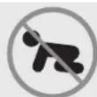
At NO time should pets or children under the age of 14 be closer to the home gym than 10 feet.
At NO time should children under the age of 14 use the home gym.
Children over the age of 14 should not use the home gym without adult supervision.


natural_image
Pure vertical gray bar with horizontal lines, no text or symbols presentASSEMBLY
IMPORTANT: READ THESE SAFETY INSTRUCTIONS BEFORE USE!

WARNING
During the assembly process there are several areas that special attention must be paid. It is very important to follow the assembly instructions correctly and to make sure all parts are firmly tightened. If the assembly instructions are not followed correctly, the home gym could have frame parts that are not tightened and will seem loose and may cause irritating noises. There should be no side-to-side play in the frame uprights. If there is any play in these areas, the home gym has not been properly assembled. To prevent damage to the home gym, the assembly instructions must be reviewed and corrective actions should be taken.
UNPACKING
Place the home gym carton on a level flat surface. It is recommended that you place a protective covering on your floor. Take CAUTION when handling and transporting this unit. Never open box when it is on its side. Unpack the unit where it will be used. FAILURE TO FOLLOW THESE INSTRUCTIONS COULD RESULT IN INJURY!


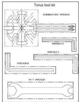
TOOLS INCLUDED:
Screwdriver
19 mm Flat Wrench
□ 13 mm/17 mm Flat Wrench
□ 3 mm Allen Wrench
□ 5 mm Allen Wrench
6 mm Allen Wrench
TORUS3 INCLUDED:
□ High Pulley Station
□ Ab Pulley Station
□ Press/row Station
□ Low Pulley Station
□ Free Motion Station
□ Weight Tower
TORUS5 INCLUDED:
□ Torus3
□ VKR Station
□ Leg Press Station
PRE ASSEMBLY
UNPACKING
Unpack the product where you will be using it. Place the bench on a level flat surface. It is recommended that you place a protective covering on your floor. Never open box when it is on its side.
NOTE: During each assembly step, ensure that ALL nuts and bolts are in place and partially threaded in before completely tightening any ONE bolt.
NOTE: A light application of grease may aid in the installation of hardware. Any grease, such as lithium bike grease is recommended.
NOTE: Please check the packing details before assembly, if there is any missing parts, contact Customer Tech Support.

NEED HELP?
If you have questions or if there are any missing parts, contact Customer Tech Support.

PACKING DETAILS
| BOX NO. | DESCRIPTION | PART NO. | VIEW | QTY | ECK | ||
| BOX 1 | IRON SHELL (LEFT) | 1 | 25 |  | |||
| IRON SHELL (RIGHT) | 26 |  | 1 | ||||
| FRONT UPRIGHT FRAME | 8 |  | 1 | ||||
| GUIDE ROD | 28 |  | 2 | ||||
| REAR UPRIGHT FRAME | 5 | 1 | |||||
| BOX 2 | BASE FRAME | 1 |  | 1 | |||
| BASE FRAME CONNECTOR | 2 |  | 1 | ||||
| LOW ROW CONNECTOR | 3 | 1 | |||||
| SIDE CONNECTOR | 7 |  | 1 | ||||
| TOP FRAME | 9 |  | 1 | ||||
| WEIGHT ROD | 29 | 1 | |||||
| LAT BAR | 30 |  | 1 | ||||
| FREE MOTION ARM STRAP | 46 |  | 2 | ||||
| ROUND TUBE | 37 | 1 | |||||

| BOX NO. | DESCRIPTION PART NO. | VIEW QTY | ||||
| BOX 2 | CALBE 1 | 119 |  | 1 | ||
| CALBE 2 | 120 |  | 1 | |||
| CALBE 3 | 121 | 1 | ||||
| CALBE 4 | 122 |  | 1 | |||
| FOAM ROLLER | 88 |  | 2 | |||
| PULLEY - ∅100 | 92 | W | 1 | |||
| PULLEY - ∅90 | 91 | WI | 1 | |||
| AXLE COLLAR | 15 |  | 2 | |||
| GYRO WHEEL | 33 |  | 2 | |||
| BUSHING | 34 | 2 | ||||
| KNOB | 86 |  | 1 | |||
| SQUARE END CAP | 79 |  | 7 | |||
| WEIGHT PIN | 81 | 1 | ||||
| BUFFER (B) | 82 |  | 4 | |||
| BUFFER (C) | 84 | 2 | ||||
| FOAM CAP | 89 |  | 2 | |||
| HOLE PLUG | 94 | 27 | ||||
| HARDWARE PACKAGE B1-B6 | 6 | |||||

| BOX NO. | DESCRIPTION PART NO. VIEW QTY | X NO. DESCRIPTION PART NO. VIEW QTY CHECK | ||||||||
| BOX 3 | TOP BRACKET 10 |  | 1 | BOX 3 | CROSS CONNECTOR | 6 |  | 1 | ||
| CENTRAL CONNECTOR | 11 |  | 1 | FOOT PLATE 4 |  | 1 | ||||
| SINGLE PULLEY BLOCK | 12 |  | 1 | ADJUSTABLE PULLEY BLOCK | 27 |  | 2 | |||
| PULLEY BLOCK | 41 |  | 4 | |||||||
| FREE MOTION ARM BRACKET | 13 |  | 1 | DOUBLE THREAD SCREW | 36 | [X4ZA] | 2 | |||
| FREE MOTION ARM | 14 |  | 2 | PIVOT AXLE | 31 |  | 2 | |||
| SEAT BRACKET CONNECTOR | 20 |  | 1 | BOX 4 | PRESS ARM | 16 |  | 1 | ||
| LEG EXTENSION | 21 | [24K] | 1 | HAND GRIP (LEFT) | 18 |  | 1 | |||
| HAND GRIP (RIGHT) | 19 | [HH80] | 1 | |||||||
| SEAT BRACKET | 22 | [HITY] | 1 | BACK PAD | 47 |  | 1 | |||
| JOINT PLATE 42 | [40DY] | 3 | SEAT PAD | 48 |  | 1 | ||||
| BACK PAD BRACKET | 24 | [WZX6] | 1 | HEAD PAD | 49 |  | 1 | |||
| PRESS ARM CONNECTOR | 17 |  | 1 | OWNER'S MANUAL | 1 | |||||

| BOX NO. | DESCRIPTION | PART NO. | QTY | CHECK | |
| BOX 5 | WEIGHT PLATE 50 | 5 |  | ||
| BOX 6 | WEIGHT PLATE 50 | 5 |  | ||
| BOX 7 | WEIGHT PLATE 50 | 5 |  | ||
| TOP PLATE 51 | 1 |  | |||
| BOX 8 | CONNECTING TUBE (LONG) | 52 1 |  | ||
| CONNECTING TUBE (SHORT) | 53 1 |  | |||
| BASE FRAME CONNECTOR | 2 1 |  | |||
| RIGHT ARMREST 54 | 1 |  | |||
| LEFT ARMREST 55 | 1 |  | |||
| LEG EXTENSION BASE FRAME | 56 1 |  | |||
| REAR SUPPORT 57 | 1 |  | |||
| UPRIGHT SUPPORT | 58 1 |  | |||
| SEAT SUPPORT 59 |  | 1 |
| BOX NO. | DESCRIPTION | PART NO. | VIEW | QTY | CHECK |
| BOX 8 | FOOT EXTENSION SUPPORT | 64 | 1 | ||
| BACK SUPPORT 60 | 1 | ||||
| ROTATE BUSHING 61 2 | |||||
| JOINT PLATE 42 5 | |||||
| CABLE 5 109 | 1 | ||||
| SQUARE END CAP 79 | 3 | ||||
| KNOB | 86 | 1 | |||
| SQUARE BLOCK | 134 | 1 | |||
| HARDWARE PACKAGE B7-B8 | 1 | ||||
| BOX 9 | FOOT PLATE (LARGE) | 65 | 1 | ||
| FOOT EXTENSION POLE (REAR) | 62 | 1 | |||
| FOOT EXTENSION POLE (FRONT) | 63 | 1 | |||
| BACK PAD | 47 | 1 | |||
| LEG PRESS SEAT PAD | 67 | 1 | |||
| PULLEY - ∅90 | 91 | WITH 6 PCS PULLEY | 6 | ||
| BOX NO. | DESCRIPTION PART NO. VIEW QTY CHECK | ||||
| BOX 10 | UPRIGHT HANDLE 68 |  | 2 | ||
| LEFT SUPPORT HANDLE | 69 1 | ||||
| RIGHT SUPPORT HANDLE | 70 |  | 1 | ||
| VKR FOOT SUPPORT | 71 | [KBDT] | 1 | ||
| ARMREST PAD | 72 2 | [W50H] | |||
| BACK PAD 47 | [45Z7] | 1 | |||
| SQUARE END CAP | 79 |  | 1 | ||
| HARDWARE PACKAGE B9 |  | 1 | |||
| BOX 11 | LOW ROW BAR 73 |  | 1 | ||
| ABDOMINAL STRAP | 74 | [DAHO] | 1 | ||
| ACCESSORIES HOOK | 75 3 |  | |||
| ANKLE STRAP 76 |  | 1 | |||
| WATER BOTTLE HOLDER | 78 | [355E] | 1 | ||
| HARDWARE PACKAGE B10 |  | 1 | |||

HARDWARE PACKAGE

B1
B2B3


B4

Torus series
B5B8
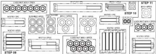
Torus series

flowchart
graph TD
    A["STEP 19"] --> B["MOTOR LAMP"]
    B --> C["Motor LAMP"]
    C --> D["MOTOR LAMP"]
    D --> E["Motor LAMP"]
    E --> F["MOTOR LAMP"]
    F --> G["Motor LAMP"]
    G --> H["MOTOR LAMP"]
    H --> I["Motor LAMP"]
    I --> J["MOTOR LAMP"]
    J --> K["Motor LAMP"]
    K --> L["MOTOR LAMP"]
    L --> M["Motor LAMP"]
    M --> N["MOTOR LAMP"]
    N --> O["Motor LAMP"]
    O --> P["MOTOR LAMP"]
    P --> Q["Motor LAMP"]
    Q --> R["MOTOR LAMP"]
    R --> S["Motor LAMP"]
    S --> T["MOTOR LAMP"]
    T --> U["Motor LAMP"]
    U --> V["MOTOR LAMP"]
    V --> W["Motor LAMP"]
    W --> X["MOTOR LAMP"]
    X --> Y["Motor LAMP"]
    Y --> Z["MOTOR LAMP"]
    Z --> AA["Motor LAMP"]
    AA --> AB["MOTOR LAMP"]
    AB --> AC["Motor LAMP"]
    AC --> AD["MOTOR LAMP"]
    AD --> AE["Motor LAMP"]
    AE --> AF["MOTOR LAMP"]
    AF --> AG["Motor LAMP"]
    AG --> AH["MOTOR LAMP"]
    AH --> AI["Motor LAMP"]
    AI --> AJ["MOTOR LAMP"]
    AJ --> AK["Motor LAMP"]
    AK --> AL["MOTOR LAMP"]
    AL --> AM["Motor LAMP"]
    AM --> AN["MOTOR LAMP"]
    AN --> AO["MOTOR LAMP"]
    AO --> AP["MOTOR LAMP"]
    AP --> AQ["MOTOR LAMP"]
    AQ --> AR["MOTOR LAMP"]
    AR --> AS["MOTOR LAMP"]
    AS --> AT["MOTOR LAMP"]
    AT --> AU["MOTOR LAMP"]
    AU --> AV["MOTOR LAMP"]
    AV --> AW["MOTOR LAMP"]
    AW --> AX["MOTOR LAMP"]
    AX --> AY["MOTOR LAMP"]
B9
B6
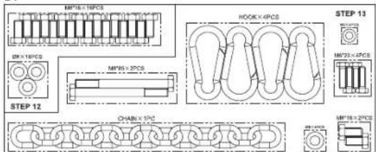
Torus series

B10
B7

flowchart
graph TD
    A["STEP 16"] --> B["STEP 17"]
    B --> C["STEP 15"]
    A --> D["MATERIALS OF CORP"]
    A --> E["MATERIALS OF NO."]
    A --> F["MATERIALS OF CORP"]
    A --> G["MATERIALS OF CORP"]
    A --> H["MATERIALS OF CORP"]
    A --> I["MATERIALS OF CORP"]
    A --> J["MATERIALS OF CORP"]
    A --> K["MATERIALS OF CORP"]
    A --> L["MATERIALS OF CORP"]
    A --> M["MATERIALS OF CORP"]
    A --> N["MATERIALS OF CORP"]
    A --> O["MATERIALS OF CORP"]
    A --> P["MATERIALS OF CORP"]
    A --> Q["MATERIALS OF CORP"]
    A --> R["MATERIALS OF CORP"]
    A --> S["MATERIALS OF CORP"]
    A --> T["MATERIALS OF CORP"]
    A --> U["MATERIALS OF CORP"]
    A --> V["MATERIALS OF CORP"]
    A --> W["MATERIALS OF CORP"]
    A --> X["MATERIALS OF CORP"]
    A --> Y["MATERIALS OF CORP"]
    A --> Z["MATERIALS OF CORP"]
Torus leg press

Tarus accessory

ASSEMBLY STEP 1


| TOOLS | 2 PCS | ||||
| 95 | #1 | M10X60 | Qty:6 | ||
| #2 | 10 | Qty:6 | |||
| #3 | M10 | Qty:6 | |||
| 97 | #1 | M10X60 | Qty:2 | ||
| 96 | #4 | M10X75 | Qty:2 | ||
| #2 | 10 | Qty:4 | |||
| #3 | M10 | Qty:2 | |||
COMPONENTS
| 156 BOX 2 | Qty:1 | BOX 1 BOX 3Qty:1 Qty:1 | |||
| 78 11 BOX 2 | BOX 1 BOX 3Qty:1 Qty:1 | Qty:1 | |||
| 79 BOX 2 | Qty:5 | ||||
A Attach FRONT UPRIGHT FRAME (8) to BASE FRAME (1) with BLOT ASSEMBLY (95) x 2.
B Attach REAR UPRIGHT FRAME (5) to BASE FRAME (1) with BLOT ASSEMBLY (95) x 2.
C Attach CENTRAL CONNECTOR (11) to BASE FRAME (1) with BLOT ASSEMBLY (95) x 2.
D Attach SQUARE END CAP (79) to BASE FRAME (1), SIDE CONNECTOR (7) and CROSS CONNECTOR (6). NOTE: Do not attach the SQUARE END CAP (79) to the right side of CROSS CONNECTOR (6) at this step if you buy TORUS5.
E Attach CROSS CONNECTOR (6) and SIDE CONNECTOR (7) to BASE FRAME (1) with BLOT ASSEMBLY (96) x 2. Note: Before attach CROSS CONNECTOR (6) to BASE FRAME (1), remember to attach BLOT (97) x2 to the bottom of CROSS CONNECTOR (6).

ASSEMBLY STEP 2


| TOOLS | 2 PCS | ||||
| 96 | #4 | M10X75 | Qty:2 | ||
| #2 | 10 | Qty:4 | |||
| #3 | M10 | Qty:2 | |||
| 99 | #6 | M10X90 | Qty:2 | ||
| #2 | 10 | Qty:4 | |||
| #3 | M10 | Qty:2 | |||
COMPONENTS
A Attach TOP FRAME (9) to REAR UPRIGHT FRAME (5) with BLOT ASSEMBLY (96) x 2. Attach JOINT PLATE (42) and TOP FRAME (9) to FRONT UPRIGHT FRAME (8) with BLOT ASSEMBLY (99) x 2.
ASSEMBLY STEP 3

| TOOLS | |||
| 83 | Qty:1 | ||
| - | Qty:1 | ||
COMPONENTS
| 28:29 5BOX 1/ | Qty:2 | BOX 2 BOX 5,6,7/ | Qty:1 Qty:15 | |
| 51:61 5BOX 7 | BOX 2 BOX 2/Qty:1 Qty:1 | Qty:4 |
A Screw GUIDE ROD (28) x 2 to the bolts on CROSS CONNECTOR (6).
B Put BUFFER (82) x1 through each GUIDE ROD (28).
C Put WEIGHT PLATE (50) through GUIDE ROD (28).
D Attach STABILIZER (83) to WEIGHT ROD (29) then put WEIGHT ROD (29) through the center of WEIGHT PLATE (50).
E Put TOP PLATE (51) through GUIDE ROD (28).
F Put BUFFER (82) x1 through each GUIDE ROD (28).
Note: There should be BUFFER (82) x 2 beneath WEIGHT PLATE (50) and BUFFER (82) x 2 above TOP PLATE (51).
G Attach WEIGHT PIN (81) to WEIGHT PLATE (50).

ASSEMBLY STEP 4


| TOOLS | 2 PCS | ||||
| 96 | #4 | M10X75 | Qty:2 | ||
| #2 | 10 | Qty:4 | |||
| #3 | M10 | Qty:2 | |||
| 100 | #7 | M10X65 | Qty:1 | ||
| #8 | M10 | Qty:2 | |||
| 101 | #9 | M10x20 | Qty:2 | ||
| #2 | 10 | Qty:2 | |||
COMPONENTS
| 10×2 8:BOX 3Qty:1 | BOX 3 BOX 2Qty:1 Qty:1 |
A Attach TOP BRACKET (10) to GUIDE ROD (28) with BOLT ASSEMBLY (101) x 2.
B Attach JOINT PLATE (42) and TOP BRACKET (10) to TOP FRAME (9) by secure with BOLT ASSEMBLY (96) x 2.
C Attach BUFFER (84) to TOP BRACKET (10) with BOLT ASSEMBLY (100).

ASSEMBLY STEP 5

| TOOLS | 2 PCS | ||||
| 96 | #4 | M10X75 | Qty:4 | ||
| #2 | 10 | Qty:8 | |||
| #3 | M10 | Qty:4 | |||
| 102 | #10 | M6X10 | Qty:1 | ||
| 103 | #39 | M10x65 | Qty:2 | ||
| #11 | 10 | Qty:2 | |||
| #2 | 10 | Qty:2 | |||
| #3 | M10 | Qty:2 | |||
COMPONENTS
A Attach FREE MOTION ARM BRACKET (13) to CENTRAL CONNECTOR (11) with BOLT ASSEMBLY (103) x 2, attach FREE MOTION ARM BRACKET (13) to FRONT UPRIGHT FRAME (8) with BOLT ASSEMBLY (96) x 2.
B Attach SQUARE END CAP (79) to BASE FRAME CONNECTOR (2).
C Attach LOW ROW CONNECTOR (3) and BASE FRAME CONNECTOR (2) to BASE FRAME (1) with BOLT ASSEMBLY (96) x 2.
D Attach FOOT PLATE (4) to LOW ROW CONNECTOR (3) and put ROUND TUBE (37) through, then secure by FLAT HEAD SCREW (102).

ASSEMBLY STEP 6
| TOOLS | 2 PCS 3 washers | ||||
| 96 | #4 | M10X75 | Qty:1 | ||
| #2 | 10 | Qty:2 | |||
| #3 | M10 | Qty:1 | |||
| 99 | #6 | M10X90 | Qty:2 | ||
| #2 | 10 | Qty:4 | |||
| #3 | M10 | Qty:2 | |||
| 104 | #12 | M10x40 | Qty:1 | ||
| 105 | #13 | M10X80 | Qty:1 | ||
| #2 | 10 | Qty:2 | |||
| #3 | M10 | Qty:1 | |||
| #14 | M10 | Qty:2 | |||
| 106 | #15 | M6X6 | Qty:4 | ||
| 150 | #2 | 10 | Qty:1 | ||
| #3 | M10 | Qty:1 | |||
COMPONENTS

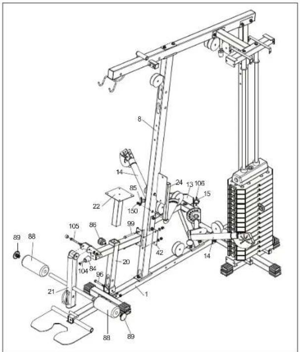
A Attach SEAT BRACKET CONNECTOR (20) to BASE FRAME (1) with BOLT ASSEMBLY (96).
B Attach SEAT BRACKET (22) to SEAT BRACKET CONNECTOR (20) and secure by KNOB (86).
C Attach SEAT BRACKET CONNECTOR (20) and JOINT PLATE (42) to FRONT UPRIGHT FRAME (8) with BOLT ASSEMBLY (99) x 2.
D Attach BUFFER (84) to SEAT BRACKET CONNECTOR (20) with PHILLIPS SCREW (104).
E Attach LEG EXTENSION (21) to SEAT BRACKET CONNECTOR (20) with BOLT ASSEMBLY (105).
F Attach FOAM ROLLER (88) to LEG EXTENSION (21), then attach FOAM CAP (89) to each FOAM ROLLER (88).
G Attach BACK PAD BRACKET (24) to FRONT UPRIGHT FRAME (8) with BOLT ASSEMBLY (150).
H Attach FREE MOTION ARM (14) x 2 to FREE MOTION ARM BRACKET (13), then attach AXLE COLLAR (15) to each FREE MOTION ARM (14) and secure by HEXAGON SOCKET HEAD SCREW (106) x 2.


ASSEMBLY STEP 7

| TOOLS | 2 PCS | ||||
| 107 | #16 | M12X20 | X4 | ||
| #17 | 12 | X4 | |||
| 108 | #17 | 12 | X4 | ||
| #18 | M12 | X4 | |||
COMPONENTS
| 16 7 1aBOX 4 | Qty:1 | BOX 3 BOX 4Qty:1 Qty:1 | ||
| 19 31 aaBOX 4 | BOX 3 BOX 3Qty:1 Qty:2 | Qty:2 |
A Attach PRESS ARM CONNECTOR (17) to TOP FRAME (9) and put PIVOT AXLE (31) through, then put DOUBLE THREAD SCREW (36) through PIVOT AXLE (31) and secure by NUT ASSEMBLY (108).
B Attach PRESS ARM (16) to PRESS ARM CONNECTOR (17) and put PIVOT AXLE (31) through, then put DOUBLE THREAD SCREW (36) through PIVOT AXLE (31) and secure by NUT ASSEMBLY (108).
C Attach HAND GRIP (LEFT) (18) to PRESS ARM (16) with BOLT ASSEMBLY (107) x 2, attach HAND GRIP (RIGHT) (19) to PRESS ARM (16) with BOLT ASSEMBLY (107) x 2.

ASSEMBLY STEP 8


| TOOLS | 2 PCS | ||||
| 98 | #5 | M10X70 | Qty:3 | ||
| #2 | 10 | Qty:6 | |||
| #3 | M10 | Qty:3 | |||
| 152 | #40 | M10X45 | Qty:7 | ||
| #2 | 10 | Qty:14 | |||
| #3 | M10 | Qty:7 | |||
| 11 | #20 | M10X85 | Qty:1 | ||
| #2 | 10 | Qty:2 | |||
| #3 | M10 | Qty:1 | |||
| 90 | Qty:6 | ||||
| 148 | Qty:1 | ||||
COMPONENTS
| 27.91 BOX 3Qty:2 | BOX 2 BOX 2Qty:12 Qty 1 |


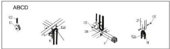
A FIGURE A: Attach PLASTIC BUSHING (90) to TOP FRAME (9), attach CABLE 1 (119) onto PULLEY P1 (91) then fix them to TOP FRAME (9) by BOLT ASSEMBLY (98).
B FIGURE B: Attach PLASTIC BUSHING (90) to TOP FRAME (9), attach CABLE 1 (119) onto PULLEY P2 (91) then fix them to TOP FRAME (9) by BOLT ASSEMBLY (98).
C FIGURE C: Put CABLE 1 (119) onto the top of PULLEY P3 (91) through the left side to the bottom then fix PULLEY P3 (91) to the back of PRESS ARM CONNECTOR (17) by BOLT ASSEMBLY (152). Put CABLE 1 (119) to PULLEY P5 (91) from the bottom of PULLEY P3 (91) and through the right side to the bottom then fix PULLEY P5 (91) to FRONT UPRIGHT FRAME (8) by BOLT ASSEMBLY (152). Put CABLE 1 (119) to PULLEY P5 (91) from the bottom of PULLEY P5 (91) through the left side to the bottom then fix PULLEY P3 (91) to the back of PRESS ARM CONNECTOR (17) by BOLT ASSEMBLY (152).
D FIGURE D: Attach PULLEY P6 (91) to FRONT UPRIGHT FRAME (8) by BOLT ASSEMBLY (98), then put CABLE 1 (119) onto the top of PULLEY P6 (91) from the bottom of PULLEY P5 (91) and through the center of FRONT UPRIGHT FRAME (8).
E FIGURE E: Put CABLE 1 (119) around PULLEY P8 (91). Attach PULLEY P28 (91) and PULLEY P8 (91) to TOP FRAME (9) with BOLT ASSEMBLY (111).
F FIGURE F: Put CABLE 1 (119) around PULLEY 10 (91) then fix to TOP BRACKET (10) with BOLT ASSEMBLY (152).
G FIGURE G: Put CABLE 1 (119) around PULLEY 11 (91) then fix to TOP BRACKET (10) with BOLT ASSEMBLY (152).
H FIGURE H: Attach CABLE 1 (119) and BIG WASHER (148) to WEIGHT ROD (29).
FIGURE I: Attach PULLEY P7 (91) to ADJUSTABLE PULLEY BLOCK (27) with BOLT ASSEMBLY (152), then put ADJUSTABLE PULLEY BLOCK (27) on CABLE 1 (119).
J FIGURE J: Attach PULLEY P9 (91) to ADJUSTABLE PULLEY BLOCK (27) with BOLT ASSEMBLY (152), then put ADJUSTABLE PULLEY BLOCK (27) on CABLE 1 (119).
ASSEMBLY STEP 9


| TOOLS | 2 PCS | ||||
| 98 | #5 | M10X70 | Qty:2 | ||
| #2 | 10 | Qty:4 | |||
| #3 | M10 | Qty:2 | |||
| 152 | #40 | M10X45 | Qty:4 | ||
| #2 | 10 | Qty:8 | |||
| #3 | M10 | Qty:4 | |||
| 112 | #21 | M10X55 | Qty:1 | ||
| #2 | 10 | Qty:2 | |||
| #3 | M10 | Qty:1 | |||
| 90 | Qty:4 | ||||
| 90S | Qty:2 | ||||
COMPONENTS
| BOX 2Qty:6 | BOX 2Qty:1 Qty:1 | BOX 2Qty:6 |
A FIGURE A: Attach PLASTIC BUSHING (90S) x 2 to LEG EXTENSION (21), then put CABLE 2 (120) (use the end without ball) through the bottom of PULLEY P12 (92) and fix to LEG EXTENSION (21) with BOLT ASSEMBLY (112).
B FIGURE B: Attach PLASTIC BUSHING (90) x 2 to SEAT BRACKET CONNECTOR (20), attach PULLEY P13 (91) to SEAT BRACKET CONNECTOR (20) by BOLT ASSEMBLY (98) and put CABLE 2 (120) through the bottom of PULLEY P13 (92).
C FIGURE C: Attach CABLE 2 (120) and PULLEY P14 (91) to BASE FRAME (1) by BOLT ASSEMBLY(152).
D FIGURE D: Attach PULLEY P15 (91) to FREE MOTION ARM BRACKET (13) by BOLT ASSEMBLY (152) then attach CABLE 2 (120) to the right side of PULLEY P15 (91) from the bottom of PULLEY P14 (91).
E FIGURE E: Attach PULLEY P16 (91) to ADJUSTABLE PULLEY BLOCK (27) by BOLT ASSEMBLY(152) and put the CABLE 2 (120) around the PULLEY P16 (91).
F FIGURE F: Attach PULLEY P17 (91) to FREE MOTION ARM BRACKET (13) by BOLT ASSEMBLY (152) and put the CABLE 2 (120) around PULLEY P17 (91) from PULLEY P16 (91).
G FIGURE G: Attach CABLE 2 (120) and PULLEY P18 (92) to FRONT UPRIGHT FRAME (8).
H FIGURE H: Assembly the left end of CABLE 2 (120).

ASSEMBLY STEP 10


| TOOLS | 2 PCS | ||||
| 110 | #19 | M10X50 | Qty:6 | ||
| #2 | 10 | Qty:12 | |||
| #3 | M10 | Qty:6 | |||
| 113 | #22 | M10X125 | Qty:1 | ||
| #2 | 10 | Qty:2 | |||
| #3 | M10 | Qty:1 | |||
| 114 | #23 | M6X45 | Qty:2 | ||
| #24 | 6 | Qty:4 | |||
| #25 | M6 | Qty:2 | |||
| 152 | #40 | M10X45 | Qty:1 | ||
| #2 | 10 | Qty:2 | |||
| #3 | M10 | Qty:1 | |||
COMPONENTS
| 12:33 S BOX 3 | Qty:1 | BOX 2 BOX 2 | Qty:2 Qty:2 | |
| 4Yrs1 Y BOX 3 | BOX 2 BOX 2 | Qty:4 Qty:9 | Qty:1 |


A FIGURE A: Attach CABLE 3 (121) and PULLEY P19 (91) to ROTATIONAL PULLEY BLOCK (23) with BOLT ASSEMBLY (110). Attach GYRO WHEEL (33) to ROTATIONAL PULLEY BLOCK (23) with BUSHING (34), secure them with BOLT ASSEMBLY (114).
B FIGURE B: Attach CABLE 3 (121) to the PULLEY P20 (91) then attach PULLEY P20 (91) to FREE MOTION ARM (14) with BOLT ASSEMBLY (110).
C FUTURE C: Attach CABLE 3 (121) on the PULLEY P21 (91), then attach PULLEY P21 (91) and PULLEY BLOCK (41) to FREE MOTION ARM BRACKET (13) with BOLT ASSEMBLY (110).
D FIGURE D: Attach PULLEY P24 (91) and PULLEY P22 (91) to CENTRAL CONNECTOR (11) with BOLT ASSEMBLY (113), then put CABLE 3 (121) around PULLEY P24 (91) from PULLEY P21.
E FIGURE E: Attach PULLEY P23 (91) to SINGLE PULLEY BLOCK (12) with BOLT ASSEMBLY (152) then put CABLE 3 (121) around PULLEY P23 (91) from PULLEY P24 (91).
F FIGURE D: Put CABLE 3 (121) around PULLEY P22 (91) from PULLEY P23.
G FIGURE F: Attach CABLE 3 (121) onto PULLEY P25 (91) from PULLEY P22 (91) then attach PULLEY P25 (91) and PULLEY BLOCK (41) to FREE MOTION ARM BRACKET (13) with BOLT ASSEMBLY (110).
H FIGURE G: Attach CABLE 3 (121) to the PULLEY P26 (91) then attach PULLEY P26 (91) to FREE MOTION ARM (14) with BOLT ASSEMBLY (110).
FIGURE H: Attach CABLE 3 (121) and PULLEY P27 (91) to ROTATIONAL PULLEY BLOCK (23) with BOLT ASSEMBLY (110). Attach GYRO WHEEL (33) to ROTATIONAL PULLEY BLOCK (23) with BUSHING (34), secure them with BOLT ASSEMBLY (114), then assembly the left end of CABLE 3 (121) with the parts.
ASSEMBLY STEP 11

| TOOLS | 2 PCS | ||||
| 152 | #40 | M10X45 | Qty:3 | ||
| #2 | 10 | Qty:6 | |||
| #3 | M10 | Qty:3 | |||
COMPONENTS
| BT BOX 2Qty:2 | 122 BOX 2Qty:1 |

Note: If you purchase TORUS5, please use CABLE5 instead of CABLE4 and DO NOT fix the cable to CROSS CONNECTOR (6) at this step, there is more detailed description to connect LEG PRESS STATION on step 21.
A FIGURE A: Attach SINGLE PULLEY BLOCK (12) to CABLE 4 (122).
B FIGURE B: The PULLEY P28 (91) has been assembled to TOP FRAME (9) by STEP 8, put CABLE 4 (122) around the PULLEY P28 (91).
C FIGURE C: Attach PULLEY P29 (91) to CROSS CONNECTOR (6) with BOLT ASSEMBLY (110), then put CABLE 4 (122) around the PULLEY P29 (91) from PULLEY P28 (91).
D FIGURE D: Attach PULLEY P30 (91) to ADJUSTABLE PULLEY BLOCK (27) with BOLT ASSEMBLY (152), then put CABLE 4 (122) around PULLEY P30 (91) from PULLEY P29 (91).
E FIGURE E: Fix CABLE 4 (122) to CROSS CONNECTOR (6) with BOLT ASSEMBLY (152).
ASSEMBLY STEP 12

| 115 | #26 | M8X16 | Qty:16 | ||
| #27 | 8 | Qty:16 |
COMPONENTS
| 25.28 BOX 1Qty:1 | BOX 1Qty:1 |
A Attach IRON SHEEL(LEFT) (25) to CROSS CONNECTOR (6) and TOP BRACKET (10) with BOLT ASSEMBLY (115).
B Attach IRON SHEEL(RIGHT) (26) to CROSS CONNECTOR (6) and TOP BRACKET (10) with BOLT ASSEMBLY (115).

ASSEMBLY STEP 13

| TOOLS | 2 PCS | ||||
| 115 | #26 | M8X16 | Qty:2 | ||
| #27 | 8 | Qty:2 | |||
| 116 | #28 | M8X85 | Qty:2 | ||
| #27 | 8 | Qty:2 | |||
| 117 | #29 | M6X20 | Qty:4 | ||
| #24 | 6 | Qty:4 | |||
| 93 | Qty:4 | ||||
| 118 | Qty:1 | ||||
COMPONENTS
| 50×68 4:BOX 2 | Qty:1 | BOX 2 BOX 4Qty:2 Qty:1 | ||
| 48×9 BOX 4 BOX 4Qty:1 Qty:1 |
A Attach SEAT PAD (48) to SEAT BRACKET (22) with BOLT ASSEMBLY (117) x 4.
B Attach HEAD PAD (49) to FRONT UPRIGHT FRAME (8) with BOLT ASSEMBLY (116) x 2.
C Attach BACK PAD (47) to FRONT UPRIGHT FRAME (8) with BOLT ASSEMBLY (115) x 2.
D Attach FREE MOTION ARM STRAP (46) x2 to CABLE 3 (121) with HOIST HOOK (93) x 2.
E Attach LAT BAR (30) to CABLE 1 (119) by HOIST HOOK (93) and CHAIN (118).


ASSEMBLY STEP 14

COMPONENTS
| 94 | BOX 2 | Qty:27 |
A Attach HOLE PLUG (94) to holes on BASE FRAME (1), REAR UPRIGHT FRAME (5) and CROSS CONNECTOR (6) as shown on the drawing.
ASSEMBLY STEP 15

natural_image
Technical line drawing of a self-assembly exercise machine (no text or symbols)TORUS3 ASSEMBLY COMPLETE!

ASSEMBLY STEP 16 (FOR LEG PRESS)

| TOOLS | 2 PCS WASFER 6 | ||||
| 95 | #1 | M10X60 | Qty:2 | ||
| #2 | 10 | Qty:2 | |||
| #3 | M10 | Qty:2 | |||
| 96 | #4 | M10X75 | Qty:6 | ||
| #2 | 10 | Qty:12 | |||
| #3 | M10 | Qty:6 | |||
| 98 | #5 | M10X70 | Qty:1 | ||
| #2 | 10 | Qty:2 | |||
| #3 | M10 | Qty:1 | |||
| 133 | #30 | M10X115 | Qty:2 | ||
| #2 | 10 | Qty:4 | |||
| #3 | M10 | Qty:2 | |||
| 135 | #31 | M10X20 | Qty:1 | ||
COMPONENTS
| 257 42BOX B | Qty:1 | BOX B | BOX B | |
| Qty:1 Qty 3 | ||||
| 58 52 6:BOX B | BOX B BOX 9 | |||
| Qty:1 Qty:1 | ||||
| 53 | BOX B | |||
| Qty:1 | BOX 9 | BOX B | ||
| Qty:1 Qty 1 | ||||
| 79 | BOX B | |||
| Qty:3 | BOX B | Qty:1 |
A Attach SQUARE END CAP (79) to BASE FRAME CONNECTOR (2) and LEG EXTENSION BASE FRAME (56).
B Attach CONNECTING TUBE (LONG) (52) and JOINT PLATE (42) to LEG EXTENSION BASE FRAME (56) with BOLT ASSEMBLY (96) x2.
C Attach CONNECTING TUBE (SHORT) (53) and JOINT PLATE (42) to LEG EXTENSION BASE FRAME (56) with BOLT ASSEMBLY (96) x2.
D Attach REAR SUPPORT (57) to LEG EXTENSION BASE FRAME (56) with BOLT ASSEMBLY (95) x2.
E Attach UPRIGHT SUPPORT (58) to LEG EXTENSION BASE FRAME (56) with BOLT ASSEMBLY (98).
F Attach BASE FRAME CONNECTOR (2) and JOINT PLATE (42) to LEG EXTENSION BASE FRAME (56) with BOLT ASSEMBLY (96) x2.
G Attach SQUARE BLOCK (134) to FOOT EXTENSION POLE (REAR) (62) with PHILLIPS SCREW (135).
H Attach part FOOT EXTENSION POLE (REAR) (62) to LEG EXTENSION BASE FRAME (56) with BOLT ASSEMBLY (133).
I Attach FOOT EXTENSION POLE (FRONT) (63) to LEG EXTENSION BASE FRAME (56) with BOLT ASSEMBLY (133).


ASSEMBLY STEP 17 (FOR LEG PRESS)

| TOOLS | 2 PCS WASFER | ||||
| 96 | #4 | M10X75 | Qty:4 | ||
| #2 | 10 | Qty:8 | |||
| #3 | M10 | Qty:4 | |||
| 98 | #5 | M10X70 | Qty:1 | ||
| #2 | 10 | Qty:2 | |||
| #3 | M10 | Qty:1 | |||
| 117 | #29 | M6X20 | Qty:4 | ||
| #24 | 6 | Qty:4 | |||
| 136 | #32 | M10X135 | Qty:2 | ||
| #2 | 10 | Qty:4 | |||
| #3 | M10 | Qty:2 | |||
| 137 | #33 | M10X40 | Qty:2 | ||
| #2 | 10 | Qty:2 | |||
| #3 | M10 | Qty:2 | |||
COMPONENTS
| 4265 5 BOX 8 | Qty:1 | BOX 8 BOX 8Qty:1 Qty:1 | ||
| 6061 6 BOX 8 | BOX 8 BOX 8Qty:1 Qty:2 | Qty:1 | ||
| 65 BOX 9 | Qty:1 | 67 BOX 9 | Qty:1 |
A Attach SEAT SUPPORT (59) to UPRIGHT SUPPORT (58) with BOLT ASSEMBLY (98).
B Attach SEAT SUPPORT (59) and JOINT PLATE (42) to REAR SUPPORT (57) with BOLT ASSEMBLY (96) x2.
C Attach RIGHT ARMREST (54) and LEFT ARMREST (55) to SEAT SUPPORT (59) with BOLT ASSEMBLY (96) x2.
D Attach LEG PRESS SEAT PAD (67) to SEAT SUPPORT (59) with BOLT ASSEMBLY (117) x4.
E Attach FOOT EXTENSION SUPPORT (64) to FOOT EXTENSION POLE (REAR) (62) and FOOT EXTENSION POLE (FRONT) (63) with ROTATE BUSHING (61) x2, secure them with BOLT ASSEMBLY (136) x2.
F Attach FOOT PLATE (LARGE) (65) to FOOT EXTENSION SUPPORT (64) with BOLT ASSEMBLY (137) x2.


ASSEMBLY STEP 18 (FOR LEG PRESS)
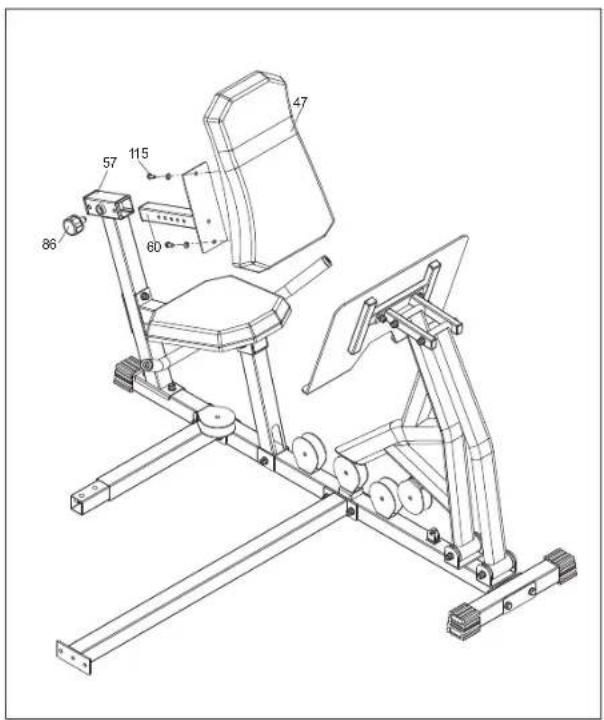
| TOOLS | 2 PCS | ||||
| 115 | #26 | M8X16 | Qty:2 | ||
| #27 | 8 | Qty:2 | |||
COMPONENTS
| A7 60 a:BOX 9Qty:1 | BOX B BOX BQty:1 Qty:1 |
A Attach BACK SUPPORT (60) to REAR SUPPORT (57) by KNOB (86).
B Attach BACK PAD (47) to BACK SUPPORT (60) with BOLT ASSEMBLY (115).
ASSEMBLY STEP 19 (FOR LEG PRESS)

| TOOLS | 2 PCS | ||||
| 152 | #40 | M10X45 | Qty:3 | ||
| #2 | 10 | Qty:6 | |||
| #3 | M10 | Qty:3 | |||
| 153 | #40 | M10X45 | Qty:1 | ||
| #2 | 10 | Qty:1 | |||
COMPONENTS
| #1 | BOX 9 | Qty:4 |
A Attach PULLEY P32 (91) to FOOT EXTENSION POLE (REAR) (62) with BOLT ASSEMBLY (153).
B Attach PULLEY P33 (91), PULLEY P35 (91) and PULLEY P36 to LEG EXTENSION BASE FRAME (56) with BOLT ASSEMBLY (152).


ASSEMBLY STEP 20 (FOR LEG PRESS)
| TOOLS | 2 PCS | ||||
| 96 | #4 | M10X75 | Qty:2 | ||
| #2 | 10 | Qty:4 | |||
| #3 | M10 | Qty:2 | |||
| 101 | #9 | M10x20 | Qty:1 | ||
| #2 | 10 | Qty:1 | |||
COMPONENTS
| 42:01 BOX 8Qty:1 | BOX 9Qty:1 |
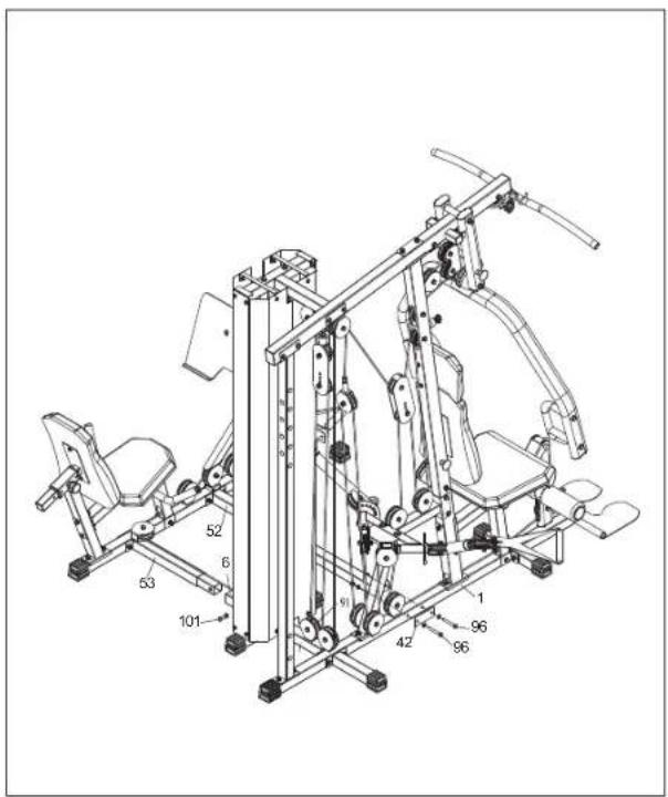
A Attach CONNECTING TUBE (SHORT) (53) to CROSS CONNECTOR (6) with BOLT ASSEMBLY (101).
B Attach CONNECTING TUBE (LONG) (52) and JOINT PLATE (42) to BASE FRAME (1) with BOLT ASSEMBLY (96)x2.
ASSEMBLY STEP 21 (FOR LEG PRESS)

If you had TORUS3 already then purchase upgrade kits for LEG PRESS, please use CABLE5 instead of CABLE 4 and follow the assembly instruction below.
A Attach PULLEY P31(91) to CROSS CONNECTOR (6) with BOLT ASSEMBLY (152).
B Attach CABLE5 (109) to SINGLE PULLEY BLOCK (12), then put CABLE5 (109) around PULLEY P28, go down to PULLEY P29, from PULLEY P29 to PULLEY P30, then around the CABLE5 ON PULLEY P31 from PULLEY P30.


ASSEMBLY STEP 22 (FOR LEG PRESS)

| TOOLS | 2 PCS | ||||
| 110 | #19 | M10X50 | Qty:1 | ||
| #2 | 10 | Qty:2 | |||
| #3 | M10 | Qty:1 | |||
| 138 | #34 | M8X30 | Qty:1 | ||
| #41 | M8 | Qty:1 | |||
COMPONENTS
| 91 | BOX 9 | Qty:1 |
| 102 | ||
| BOX 8 | ||
| L=750 | ||
| Qty:1 | ||
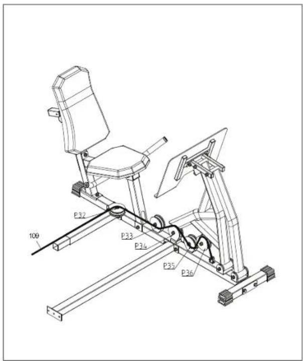
A Attach CABLE5 (109) around PULLEY P32, then go to the bottom of PULLEY P33.
B Put CABLE 5 (109) to the top of PULLEY P34 (91) then attach to FOOT EXTENSION POLE (REAR) (62) with BOLT ASSEMBLY (110).
C Put CABLE5 (109) through the bottom of PULLEY P35 then to the top of PULLEY P36.
D Fix CABLE5 (109) to LEG EXTENSION BASE FRAME (56) with BOLT ASSEMBLY (138).
ASSEMBLY STEP 23 (FOR LEG PRESS)
TOURS3 ADD LEG PRESS STATION COMPLETE!


ASSEMBLY STEP 24 (FOR VKR)

| TOOLS | 2 PCS | ||||
| 98 | #5 | M10X70 | Qty:2 | ||
| #2 | 10 | Qty:4 | |||
| #3 | M10 | Qty:2 | |||
| 144 | #30 | M10x115 | Qty:2 | ||
| #2 | 10 | Qty:4 | |||
| #3 | M10 | Qty:2 | |||
| 145 | #37 | M8x65 | Qty:6 | ||
| #27 | 8 | Qty:6 | |||
| 147 | #38 | M12x25 | Qty:2 | ||
| #17 | 12 | Qty:2 | |||
COMPONENTS
| 65 47 BOX 10 | Qty:2 | BOX 10 BOX 10Qty:1 Qty:1 | ||
| 71 70 BOX 10 | BOX 10 BOX 10Qty:1 Qty:1 | Qty:2 | ||
| 75 BOX 10 | Qty:1 | |||
A Attach SQUARE END CAP (79) to VKR FOOT SUPPORT (71), then attach VKR FOOT SUPPORT (71) to REAR UPRIGHT (5) with BOLT ASSEMBLY (144).
B Attach LEFT SUPPORT POLE SET (69) and RIGHT SUPPORT POLE SET (70) to REAR UPRIGHT (5) by BOLT ASSEMBLY (98) x 2.
C Attach ARMREST PAD (72) x2 to LEFT SUPPORT POLE SET (69) and RIGHT SUPPORT POLE SET (70) with BOLT ASSEMBLY (145).
D Attach UPRIGHT HANDLE (68) x2 to LEFT SUPPORT POLE SET (69) and RIGHT SUPPORT POLE SET (70) with BOLT ASSEMBLY (147).
E Attach BACK PAD (47) to REAR UPRIGHT (5) with BOLT ASSEMBLY (145).


ASSEMBLY STEP 25 (FOR VKR)

natural_image
Technical line drawing of a mechanical exercise machine (no text or symbols)VKR ASSEMBLY COMPLETE!
ASSEMBLY STEP 26

| TOOLS | |||||
| 93 | Qty:3 | ||||
| 118 | Qty:1 | ||||
COMPONENTS
| 73 BOX 11 | Qty:1 | 72 BOX 11 | Qty:1 | 76 BOX 11 | Qty:1 |
| 78 BOX 11 | Qty:1 |
A Attach LOW ROW BAR (73) or ANKLE STRAP (76) to CABLE2 (120) with CHAIN (118) and HOIST HOOK (93).
B Attach LOW ROW BAR (73) to CABLE2 (120) with CHAIN (118) and HOIST HOOK (93).
C Attach ABDOMINAL STRAP (74) to CABLE2 (120) with HOIST HOOK (93).
D Attach WATER BOTTLE HOLDER (78) to IRON SHELL (26).

ASSEMBLY STEP 27
natural_image
Technical line drawing of a mechanical exercise machine (no text or symbols visible)COMPONENTS
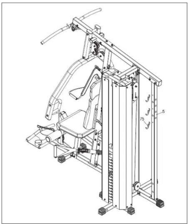
| 75 | BOX 10 | Qty:3 |
A Attach ACCESSORIES HOOK (75) x3 to REAR UPRIGHT FRAME (5).
ASSEMBLY STEP 28

A We provide some foot pads for TORUS, if the floor is uneven, you can insert these pads beneath the machine to enhance the stability.


ASSEMBLY STEP 29

natural_image
Technical line drawing of a gym rehabilitation machine with adjustable arms and legs (no text or labels)TORUS5 ASSEMBLY COMPLETE!
BEFORE YOU BEGIN
CONGRATULATIONS! on choosing your home gym. You've taken an important step in developing and sustaining an exercise program! Your home gym is a tremendously effective tool for achieving your personal fitness goals. Regular use of your home gym can improve the quality of your life in so many ways.
HERE ARE JUST A FEW OF THE HEALTH BENEFITS OF EXERCISE:
- Improved Muscle Tone and Strength
• Increased Daily Energy Levels
• A Healthier Heart - Weight Loss
The key to reaping these benefits is to develop an exercise habit. Your new home gym will help you eliminate obstacles that prevent you from exercising. Inclement weather and darkness won't interfere with your workout when you use your home gym in the comfort of your home. This guide provides you with basic information for using and enjoying your new machine.
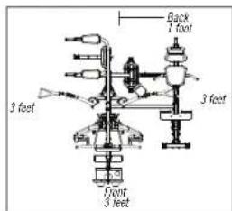
Place the home gym on a level surface. There should be 1 foot of clearance behind the home gym, 3 feet on each side and 3 feet in front. Do not place the home gym in any area that will block any vent or air openings. The home gym should not be located outdoors.

WARNING
SEAT ASSEMBLY PIN
Ensure that the seat assembly safety pin is fully inserted before using the home gym. Failure to do so may result in injury!
PROPER USAGE
Make sure to follow the MAINTENANCE schedule in this manual. Stop your workout immediately if you feel pain, faint, dizzy or are short of breath.

WARNING
Do not operate the home gym if there is any noticeable damage to the cables or pulleys. If any damage is noticeable, contact customer tech support at the number located on the back panel of this manual.
CONDITIONING GUIDELINES
ALWAYS CONSULT YOUR PHYSICIAN BEFORE BEGINNING AN EXERCISE PROGRAM.
HOW OFTEN? (Frequency of Workouts)
The American Heart Association recommends that you exercise at least 3 to 4 days per week to maintain fitness. If you have other goals such as weight or fat loss, you will achieve your goal faster with more frequent exercise. Whether it's 3 days or 6 days, remember that your ultimate goal should be to make exercise a lifetime habit. Many people are successful staying with a fitness program if they set aside a specific time of day to exercise. It doesn't matter whether it's in the morning before breakfast, during lunch hour or while watching the evening news. What's more important is that it's a time that allows you to keep a schedule, and a time when you won't be interrupted. To be successful with your fitness program, you have to make it a priority in your life. So decide on a time, pull out your day planner and pencil in your exercise times for the next month!
HOW LONG? (Duration of Workouts)
For aerobic exercise benefits, it's recommended that you exercise from between 24 and 60 minutes per session. But start slowly and gradually increase your exercise times. If you've been sedentary during the past year, it may be a good idea to keep your exercise times to as little as 5 minutes initially. Your body will need time to adjust to the new activity. If your goal is weight loss, a longer exercise session at lower intensities has been found to be most effective.
HOW HARD? (Intensity of Workouts)
How hard you workout is also determined by your goals. If you use your home gym to prepare for a 5K run, you will probably work out at a higher intensity than if your goal is general fitness. Regardless of your long term goals, always begin an exercise program at low intensity. Aerobic exercise does not have to be painful to be beneficial! There are two ways to measure your exercise intensity. The first is by monitoring your heart rate (using the grip pulse handlebars or a wireless chest transmitter - may be sold separately), and the second is by evaluating your perceived exertion level (this is simpler than it sounds!).
PERCEIVED EXERTION LEVEL
A simple way to gauge your exercise intensity is to evaluate your perceived exertion level. While exercising, if you are too winded to maintain a conversation without gasping, you are working out too hard. A good rule of thumb is to work to the point of exhilaration, not exhaustion. If you cannot catch your breath, it's time to slow down. Always be aware of these warning signs of overexertion.
GENERAL STRENGTH TRAINING GUIDELINES
- It is recommended that you perform at least 5-10 minutes of cardiovascular exercise before beginning your strength routine in order to warm the muscles, increase the heart rate, and prepare your body for strength training.
• Always raise and lower the weight in a smooth, slow, and controlled motion. - Try not to hold your breath during strength training exercises. It is recommended that you exhale as you raise the weight and inhale as you lower the weight.
- It is recommended that each muscle group be allowed to rest 48 hours between strength training.
- Complete each strength routine with a few simple stretches to maintain flexibility, and allow your body to cool-down after your session.


STRETCHING
STRETCH FIRST
Before using your product, it is best to take a few minutes doing a few gentle stretching exercises. Stretching prior to exercise will improve flexibility and reduce chances of exercise related injury. Ease into each of these stretches with a slow gentle motion. Do not stretch to the point of pain. Make sure not to bounce while doing these stretches.
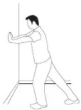
1. STANDING CALF MUSCLE STRETCH
Stand near a wall with the toes of tour left foot about 18" from the wall, and the right foot about 12" behind the other foot. Lean forward, pushing against the wall with your palms. Keep your heels flat and hold this position for a count of 15 seconds. Make sure that you do not bounce while stretching. Repeat on the other side.
2. STANDING QUADRICEPS STRETCH
Using a wall to provide balance, grasp your left ankle with your left hand and hold your foot against the back of your thigh for 15 seconds. Repeat with your right ankle and hand.
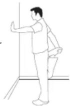

62. SITTING HAMSTRING & LOWER BACK MUSCLE STRETCH
Sit on the floor with your legs together and straight out in front of you. Do not lock your knees. Extend your fingers towards your toes and hold for a count of 15 seconds. Make sure that you do not bounce while stretching. Sit upright again. Repeat one time.
TIPS

THE IMPORTANCE OF WARM UP & COOL DOWN

WARM UP
Always perform 10-15 minutes of aerobic activity before beginning your strength training session. This warm-up will limber your muscles and prepare them for more strenuous exercise. Make sure that you warm-up on your product at a slow pace. The warm up should gradually increase your heart rate into your heart rate training zone and increase core body temperature.
COOL DOWN
Never stop exercising suddenly! A cool-down period of 3-5 minutes allows your heart to readjust to the decreased demand. Your cool-down period should consist of repeating the stretching exercises listed above to loosen and relax your muscles.
TIPS

ACHIEVING YOUR FITNESS GOALS
An important step in developing a long term fitness program is to determine your goals. Is your primary goal for exercising to lose weight? Improve muscle tone and/or strength? Reduce stress? Knowing what your goals are will help you develop a more successful exercise program. Below are some common exercise goals:
- Weight Loss - lower intensity, longer duration workouts
- Improve Body Shape and Tone - interval workouts, alternate between hi and low intensities
- Increased Energy Level - more frequent daily workouts
- Improved Sports Performance - high intensity workouts
If possible try to define your personal goals in precise, measurable terms, and then put your goals in writing. The more specific you can be, the easier it will be to track your progress. If your goals are long term, divide them up into monthly and weekly segments. Longer term goals can lose some of the immediate motivation benefits. Short term goals are easier to achieve.
TRAINING INSTRUCTION


natural_image
Person using a TCRUZS machine with side arm diagrams showing human body silhouette (no text or symbols on the machine itself)
natural_image
Person using a T-TOOL rehabilitation machine with body diagrams on the left (no text or symbols on the machine itself)CABLE FLY
- Turn the free motion arm upright.
- Hold the free motion straps by your both hands and extend your arms as wide as possible.
- Pull the straps forward until both of hands touch.
- Slowly return to starting position.
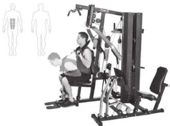
LAT PULL DOWN
- Sit on the machine, reach up, and grab the lat bar with a wide grip.
- Pull the bar down toward your body in front of the chest.
- Return slowly to starting position.
natural_image
Person using a TORS machine with body diagrams in the background (no text or symbols on the machine itself)SEATED ABDOMINAL CRUNCH
- Attach ab strap or free motion arm straps on the machine.
- Sit upright with your back supported by the back pad.
- Hold the straps and bend your torso towards your knees.
- Slowly back to the starting position.

natural_image
Person using a Torgus machine in a gym, with corresponding body diagrams showing male and female human silhouettes (no text or symbols on equipment)SEATED LEG EXTENSION
- Adjust the seat height to place your knees as close as possible to the leg lever pivot.
- Place the front of your shins behind the leg roller at the bottom of the machine.
- With your back against the pad, extend your legs forward, straightening, but not locking, your knees.
- Return slowly to starting position.

natural_image
Person using a TOMS machine with body diagrams showing human and individual views (no text or symbols on the machine itself)
natural_image
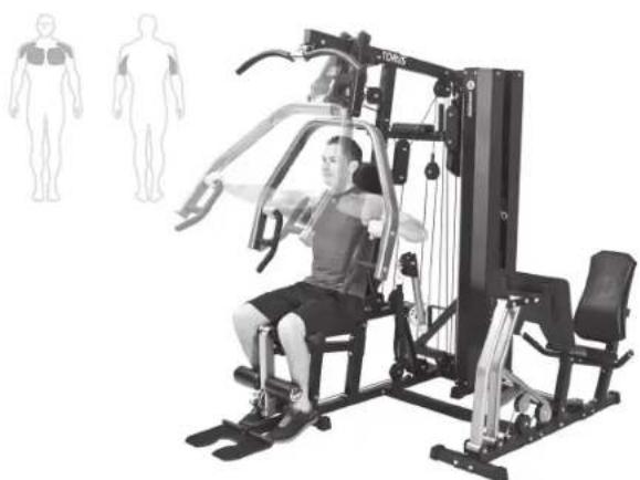
Person using a TOMUS machine in a row, with human body diagrams on the left (no text or symbols on the machine itself)STANDARD CHEST PRESS
- Adjust the seat height so either the upper or lower grips align vertically with the center of your chest.
- Adjust the press arms with the adjustment mechanism, until they are in a comfortable forward to back position for your chest press.
- Keeping arms as close to parallel to the floor as possible, press forward and return slowly.
SEATED CABLE ROW
- Attach the short handle to the lower pulley.
- Sit facing the machine with your legs slightly bent and keep them bent during the exercise.
- Sit erect and pull your hands towards your upper abdominal area.
- Slowly return to the starting position.

natural_image
Person performing a fitness exercise using a leg press machine, with an inset showing a human body silhouette (no text or symbols present)TRICEPS DIPS
- Face the machine and grip the dip station handles firmly.
- Use the step to assist in getting into the upright position with all your weight supported by your arms and hands.
- Slowly bend your elbows until they reach 90 degrees and then press your body back up to the starting position.
natural_image
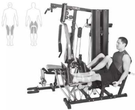
Person using a TCRUS machine with body diagrams on the left (no text or symbols on the machine itself)LEG PRESS
- Sit on the leg press station and adjust the back pad to a comfortable position.
- Put your feet on the foot plate and bend your knees to a 90 degree angle.
- Press your knees straight while gripping the seat support handles.
- Slowly return to starting position.

TROUBLESHOOTING
Your home gym is designed to be reliable and easy to use. However, if you experience a problem, please reference the troubleshooting guide listed below.
PROBLEM: The cables feel rough and are noisy during use.
SOLUTION: Verify the following:
IS THERE ANY NOTICABLE DAMAGE TO THE CABLES?
IF YES:
- Contact customer tech support and replace the cable(s).
IF NO:
- Verify that all cables are secured into the pulleys.
- Verify that the weight stack guiderods are lubricated.
- Verify that there is no excessive slack in the cables.
NOTE: If there is excessive slack adjust cable tension (see next page)
PROBLEM: Weight selector pin cannot be inserted.
SOLUTION: Verify the following:
ARE THE HOLES ALLIGNED THROUGH THE WEIGHT PLATE AND BAYONETTE?
IF YES:
- Verify that the selector pin isn't bent or damaged.
IF NO:
- Adjust threaded bolt on top plate so that the holes in the bayonette align with the weight plate.
NOTE: Always maintain at least 12 " of threaded bolt in bayonette.
If the above troubleshooting section does not remedy the problem, discontinue use.
PLEASE CALL CUSTOMER TECH SUPPORT AT THE NUMBER ON THE BACK PANEL.
The following information may be asked of you when you call. Please have these items readily available:
- Model Name
- Serial Number
- Date of Purchase (receipt or credit card statement)
In order for Customer Tech Support to service your home gym they may need to ask detailed questions about the symptoms that are occurring. Some troubleshooting questions that may be asked are:
• How long has this problem been occurring?
- Does this problem occur with every use? With every user?
- If you are hearing a noise, does it come from the front or the back? What kind of noise is it (thumping, grinding, squeaking, chirping etc.)?
- Has the machine been lubricated and maintained per the maintenance schedule?
Answering these and other questions will give the technicians the ability to send proper replacement parts and the service necessary to get you and your Horizon Fitness home gym functioning again!
MAINTENANCE
Cleanliness of your home gym and its operation environment will keep maintenance problems and service calls to a minimum. For this reason, we recommend that the following preventive maintenance schedule be followed.

AFTER EACH USE (DAILY)
- Wipe upholstery, handgrips, bars, and frame (if needed) with a mild cleaning solution.
EVERY WEEK
- Lubricate guide rods with a spray or gel silicone lubricant. Inspect cable ends and cable insulation for damage.
EVERY MONTH - IMPORTANT!
- Inspect all frame bolts and tighton as needed.
Please contact Horizon Fitness with questions about applying lubricant to your home gym.
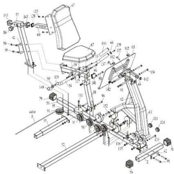
TORUS3 EXPLODED VIEW

LEG PRESS EXPLODED VIEW VKR EXPLODED VIEW

TORUS PARTS LIST
| NO. | DESCRIPTION | QTY | NO. | DESCRIPTION | QTY |
| 1 | BASE FRAME | 1 | 26 | IRON SHELL (RIGHT) | 1 |
| 2 | FRONT BASE TUBE | 1 | 27 | ADJUSTABLE PULLEY BLOCK | 2 |
| 3 | LOW ROW CONNECTOR 1 | 28 | GUIDE ROD | 2 | |
| 4 | FOOT PLATE 1 | 29 | WEIGHT ROD | 1 | |
| 5 | REAR UPRIGHT | 1 | 30 | LAT BAR | 1 |
| 6 | BOTTOM CROSS CONNECTOR | 1 | 31 | PIVOT AXLE | 2 |
| 7 | SIDE ROW CONNECTOR 1 | 32 | PULL PIN | 2 | |
| 8 | FRONT UPRIGHT 1 | 33 | GYRO WHEEL | 2 | |
| 9 | TOP FRAME | 1 | 34 | BUSHING | 2 |
| 10 | FIXING BRACKET | 1 | 35 | INSERT PIN | 2 |
| 11 | REAR CONNECT 1 | 36 | DOUBLE THREAD SCREW | 2 | |
| 12 | SINGLE PULLEY BLOCK 1 | 37 | ROUND TUBE | 1 | |
| 13 | CABLE ARM ASSEMBLE | 1 | 38 | INTENSIFY PLATE (1) | 1 |
| 14 | CABLE ARM | 2 | 39 | INTENSIFY PLATE (2) | 2 |
| 15 | AXLE COLLAR 2 | 40 | INTENSIFY PLATE (3) | 1 | |
| 16 | PRESS ARM 1 | 41 | PULLEY BLOCK | 4 | |
| 17 | PRESS ARM SELECTOR | 1 | 42 | JOINT PLATE | 3 |
| 18 | HAND GRIP (LEFT) | 1 | 43 | BIG WASHER | 2 |
| 19 | HAND GRIP (RIGHT) 1 | 44 | IRON BUSHING | 4 | |
| 20 | SEAT CUSHION SUPPORT 1 | 45 | PLASTIC BUSHING | 2 | |
| 21 | LEG EXTENSION | 1 | 46 | FREE MOTION ARM STRAP | 2 |
| 22 | CUSHION SUPPORT | 1 | 47 | BACK PAD | 1 |
| 23 | ROTATIONAL PULLEY BLOCK | 2 | 48 | SEAT PAD | 1 |
| 24 | BACK CUSHION SUPPORT | 1 | 49 | HEAD PAD | 1 |
| 25 | IRON SHELL (LEFT) | 1 | 50 | WEIGHT PLATE | 15 |
| 51 | TOP PLATE | 1 | 98 | BOLT M10×70 | 5 |
| 79 | SQUARE END CAP | 7 | WASHERS | 10 | |
| 80 | BUFFER (A) 1 | LOCK NUT | 5 | ||
| 81 | WEIGHT PIN 1 | 99 | BOLT M10×90 | 4 | |
| 82 | BUFFER (B) | 4 | WASHERS | 8 | |
| 83 | STABILIZER | 1 | LOCK NUT | 4 | |
| 84 | BUFFER (C) 2 | 100 | PHILLIPS SCREW M10×65 | 1 | |
| 85 | YELLOW HANDLE 4 | NUT | 2 | ||
| 86 | KNOB | 1 | 101 | BOLT M10×20 + WASHER | 2 |
| 87 | SQUARE BUSHING-45 | 1 | 102 | FLAT HEAD SCREW M6×10 | 1 |
| 88 | FOAM ROLLER 2 | 103 | BOLT M10×65 | 2 | |
| 89 | FOAM CAP 2 | BIG WASHER | 2 | ||
| 90 | PLASTIC BUSHING | 10 | WASHER | 2 | |
| 90S | SHORT PLASTIC BUSHING | 2 | LOCK NUT | 2 | |
| 91 | PULLEY - ∅90 29 | 104 | PHILLIPS SCREW M10×40 | 1 | |
| 92 | PULLEY - ∅100 1 | 105 | BOLT M10×80 | 1 | |
| 93 | HOIST HOOK | 4 | WASHERS | 2 | |
| 94 | HOLE PLUG | 27 | LOCK NUT | 1 | |
| 95 | SQUARE NECK BOLT M10×60 6 | NELON CAP | 2 | ||
| WASHER 6 | 106 | HEXAGON SOCKET HEAD SCREW M6×6 | 4 | ||
| LOCK NUT 6 | 107 | BOLT M12×20 | 4 | ||
| 96 | HEX BOLT M10×75 | 11 | WASHER 4 | ||
| WASHERS | 22 | 108 | WASHER 12 | 4 | |
| LOCK NUT | 11 | LOCK NUT M12 | 4 | ||
| 97 | SQUARE NECK BOLT M10×60 | 2 | 110 | BOLT M10×50 | 6 |
| 110 | WASHERS | 12 | 123 | ROUND PLUG-Φ25 | 2 |
| LOCK NUT | 6 | 124 | ROUND BUSHING-Φ50 | 2 | |
| 111 | BOLT M10×85 1 | 125 | OVAL PLUG - 8040 | 5 | |
| WASHERS 2 | 126 | ROUND PLUG-Φ30 | 2 | ||
| LOCK NUT | 1 | 127 | RECTANGLE PLUG - 7050 | 2 | |
| 112 | BOLT M10×55 | 1 | 128 | SQUARE PLUG - 38 | 2 |
| WASHER 2 | 129 | SQUARE PLUG - 25 | 2 | ||
| LOCK NUT 1 | 130 | SPRING | 4 | ||
| 113 | BOLT M10×125 | 1 | 131 | FOAM TUBE LAT BAR | 2 |
| WASHERS | 2 | 132 | CIRCLIPS FOR SHAFT | 2 | |
| LOCK NUT 1 | 148 | BIG WASHER 12 | 1 | ||
| 114 | BOLT M6×45 2 | 149 | CORE PULLING RIVET | 12 | |
| WASHERS | 4 | 150 | WASHER 10 + LOCK NUT M10 | 1 | |
| LOCK NUT | 2 | 151 | PROTECT PAD | 8 | |
| 115 | BOLT M8×16 18 | 152 | BOLT M10×45 15 | ||
| WASHER 18 | WASHER | 30 | |||
| 116 | BOLT M8×85 | 2 | LOCK NUT | 15 | |
| WASHER | 2 | 154 | UBBER PLATE | 2 | |
| 117 | BOLT M6×20 4 | 155 | CROSS SOCKET HEAD SCREWS M5×10 | 4 | |
| WASHER 4 | #1 | SQUARE NECK BOLT M10×60 | 8 | ||
| 118 CHAIN 1 | #2 | WASHER 10 | 101 | ||
| 119 CABLE 1 1 | #3 | LOCK NUT M10 | 54 | ||
| 120 CABLE 2 1 | #4 | BOLT M10×75 11 | |||
| 121 CABLE 3 1 | #5 | BOLT M10×70 | 5 | ||
| 122 | CABLE 4 | 1 | #6 | BOLT M10×90 | 4 |
| NO. | DESCRIPTION | QTY |
| #7 | CROSS RECESSED COUNTERSUNK HEAD SCREW M10×65 | 1 |
| #8 | HEXAGON NUT M10 2 | |
| #9 | BOLT M10×20 | 2 |
| #10 | CROSS PAD HEAD SCREW M6×10 | 1 |
| #11 BIG WASHER 10 2 | ||
| #12 | CROSS RECESSED COUNTERSUNK HEAD SCREWS M10×40 | 1 |
| #13 | BOLT M10×80 | 1 |
| #14 | NELON CAP 10 | 2 |
| #15 SET SCREW M6×6 4 | ||
| #16 BOLT M12×20 4 | ||
| #17 | WASHER 12 | 8 |
| #18 | LOCK NUT M12 | 4 |
| #19 BOLT M10×50 6 | ||
| #20 BOLT M10×85 1 | ||
| #21 | BOLT M10×55 | 1 |
| #22 | BOLT M10×125 | 1 |
| #23 BOLT M6×45 2 | ||
| #24 WASHER 6 8 | ||
| #25 | LOCK NUT M6 | 2 |
| #26 | BOLT M8×16 | 18 |
| #27 WASHER 8 20 | ||
| #28 BOLT M8×85 2 | ||
| #29 BOLT M6×20 4 | ||
| #39 BOLT M10×65 2 | ||
| #40 BOLT M10×45 15 | ||
LEG EXTENSION PART LIST
| NO. | DESCRIPTION | QTY |
| 52 | CONNECTING TUBE (LONG) | 1 |
| 53 | CONNECTING TUBE (SHORT) | 1 |
| 2 | BASE FRAME CONNECTOR 1 | |
| 54 | RIGHT ARMREST 1 | |
| 55 | LEFT ARMREST | 1 |
| 56 | LEG EXTENSION BASE FRAME | 1 |
| 57 | REAR SUPPORT 1 | |
| 58 | UPRIGHT SUPPORT 1 | |
| 59 | SEAT SUPPORT | 1 |
| 60 | BACK SUPPORT | 1 |
| 61 | ROTATE BUSHING 2 | |
| 62 | FOOT EXTENSION POLE (REAR) 1 | |
| 63 | FOOT EXTENSION POLE (FRONT) | 1 |
| 64 | FOOT EXTENSION SUPPORT | 1 |
| 65 | FOOT PLATE (LARGE) 1 | |
| 42 | JOINT PLATE 5 | |
| 66 | FOAM CHECK RING | 2 |
| 67 | LEG PRESS SEAT PAD | 1 |
| 47 | BACK PAD 1 | |
| 79 | SQUARE END CAP 3 | |
| 91 | PULLEY - ∅90 | 6 |
| 95 | SQUARE NECK BOLT M10×60 | 2 |
| WASHER | 2 | |
| LOCK NUT | 2 | |
| 96 | BOLT M10×75 | 12 |
| NO. | DESCRIPTION | QTY |
| 138 | LOCK NUT | 1 |
| 101 | BOLT M10×20 | 1 |
| WASHER 1 | ||
| 139 | HEX SOCKET HEAD SCREWS M8×20 2 | |
| 140 | FOAM TUBE - ∅32*125 | 2 |
| 141 | SQUARE PLUG - 50 | 1 |
| 124 | ROUND BUSHING - ∅50 4 | |
| 142 | RECTANGLE PLUG - 3020 6 | |
| 143 | SQUARE BUSHING - 50 | 2 |
| 128 | SQUARE PLUG - 38 | 1 |
| 109 | CABLE 5 1 | |
| 152 | BOLT M10×45 3 | |
| WASHER | 6 | |
| LOCK NUT | 3 | |
| 153 | BOLT M10×45 + WASHER 1 | |
| #1 | SQUARE NECK BOLT M10×60 2 | |
| #2 | WASHER 10 | 50 |
| #3 | LOCK NUT M10 | 26 |
| #4 | BOLT M10×75 12 | |
| #5 | BOLT M10×70 2 | |
| #9 | BOLT M10×20 1 | |
| #19 | BOLT M10×50 1 | |
| #24 | WASHER 6 | 4 |
| #26 | BOLT M8×16 | 2 |
| #27 | WASHER 8 | 2 |
| NO. | DESCRIPTION | QTY |
| #29 | BOLT M6×20 | 4 |
| #30 | BOLT M10×115 | 2 |
| #31 | CROSS SOCKET HEAD SCREWS M10×20 | 1 |
| #32 | BOLT M10×135 | 2 |
| #33 | HEX SOCKET HEAD SCREWS M10×40 | 2 |
| #34 | BOLT M8×30 | 1 |
| #36 | HEX SOCKET HEAD SCREWS M8×20 2 | |
| #40 | BOLT M10×45 4 | |
| #41 | LOCK NUT M8 1 |
VKR PART LIST
| NO. | DESCRIPTION | QTY | NO. | DESCRIPTION | QTY |
| 68 | UPRIGHT HANDLE | 2 | #27 | WASHER 8 | 6 |
| 69 | LEFT SUPPORT HANDLE | 1 | #30 | BOLT M10×115 | 2 |
| 70 | RIGHT SUPPORT HANDLE 1 | #37 | BOLT M8×65 6 | ||
| 71 | VKR FOOT SUPPORT 1 | #38 | BOLT M12×25 2 | ||
| 66 | FOAM CHECK RING | 4 | |||
| 72 | ARMREST PAD | 2 | |||
| 47 | BACK PAD 1 | ||||
| 98 | BOLT M10×70 2 | ||||
| WASHER | 4 | ||||
| LOCK NUT | 2 | ||||
| 139 | HEX SOCKET HEAD SCREWS M8×20 4 | ||||
| 144 | BOLT M10×115 2 | ||||
| WASHER | 4 | ||||
| LOCK NUT | 2 | ||||
| 145 | BOLT M8×65 6 | ||||
| WASHER 6 | |||||
| 140 | FOAM TUBE-Φ32*125 | 2 | |||
| 146 | FOAM TUBE-Φ32*170 | 2 | |||
| 147 | BOLT M12×25 2 | ||||
| WASHER 2 | |||||
| 79 | SQUARE END CAP 1 | ||||
| #2 | WASHER 10 8 | ||||
| #3 | LOCK NUT M10 4 | ||||
| #5 | BOLT M10×70 2 | ||||
| #17 | WASHER 12 | 2 | |||
ACCESSORIES PART LIST
| NO. | DESCRIPTION | QTY |
| 73 | LOW ROW BAR | 1 |
| 74 | ABDOMINAL STRAP | 1 |
| 75 | ACCESSORIES HOOK 3 | |
| 76 | ANKLE STRAP 1 | |
| 78 | WATER BOTTLE HOLDER | 1 |
| 93 | HOIST HOOK 3 | |
| 102 | PHILLIP SCREW M6×16 3 | |
| 118 | CHAIN | 1 |
| 125 | OVAL PLUG - 8040 | 2 |
| 126 | ROUND PLUG-Φ30 2 | |
| 140 | FOAM TUBE-Φ32*125 2 | |
| #35 | CROSS PAD HEAD SCREW M6×16 | 3 |
TRAINING LOG SHEET
MUSCLE GROUP=UPPER BODY, TORSO, LOWER BODY
| DAY | EXERCISE | MUSCLE GROUP WEIGHT USED FREQUENCY TIME | |||


| 2017 | 2016 | |
| Cost of sales | 3,459 | 3,384 |
| Gross profit | 1,084 | 1,061 |
| Net profit | 1,084 | 1,061 |

natural_image
Blank white image with no visible content, text, or symbols.
natural_image
Blank white image with no visible content, text, or symbols.
natural_image
Blank white image with no visible content, text, or symbols.
natural_image
Blank white image with no visible content, text, or symbols.
natural_image
Blank white image with no visible content, text, or symbols.
natural_image
Blank white image with no visible content, text, or symbols.
natural_image
Blank white image with no visible content, text, or symbols.
natural_image
Blank white image with no visible content, text, or symbols.
natural_image
Blank white image with no visible content, text, or symbols.
natural_image
Blank white image with no visible content, text, or symbols.
natural_image
Blank white image with no visible content, text, or symbols.

| 2017 | 2016 | |
| Cost of sales | 3,459 | 3,380 |
| Gross profit | 1,046 | 1,038 |
| Net profit | 1,046 | 1,038 |

natural_image
Blank white image with no visible content, text, or symbols.
natural_image
Blank white image with no visible content, text, or symbols.
natural_image
Blank white image with no visible content, text, or symbols.
natural_image
Blank white image with no visible content, text, or symbols.
natural_image
Blank white image with no visible content, text, or symbols.
natural_image
Blank white image with no visible content, text, or symbols.
natural_image
Blank white image with no visible content, text, or symbols.
natural_image
Blank white image with no visible content, text, or symbols.
natural_image
Blank white image with no visible content, text, or symbols.
natural_image
Blank white image with no visible content, text, or symbols.
natural_image
Blank white image with no visible content, text, or symbols.
HORIZON
FITNESS
HOME GYM OWNER'S MANUAL
Torus 5 Owner's Manual 080913 Rev.2.2 © 2013 Horizon Fitness
- INTRODUCTION
- IMPORTANT SAFETY PRECAUTIONS
- SAVE THESE INSTRUCTIONS
- WARNING
- ASSEMBLY
- UNPACKING
- TOOLS INCLUDED:
- TORUS3 INCLUDED:
- TORUS5 INCLUDED:
- PRE ASSEMBLY
- NEED HELP?
- HARDWARE PACKAGE
- ASSEMBLY STEP 1
- ASSEMBLY STEP 2
- ASSEMBLY STEP 3
- ASSEMBLY STEP 4
- ASSEMBLY STEP 5
- ASSEMBLY STEP 6
- COMPONENTS
- ASSEMBLY STEP 7
- ASSEMBLY STEP 8
- ASSEMBLY STEP 9
- ASSEMBLY STEP 10
- ASSEMBLY STEP 11
- ASSEMBLY STEP 12
- ASSEMBLY STEP 13
- ASSEMBLY STEP 14
- ASSEMBLY STEP 15
- ASSEMBLY STEP 16 (FOR LEG PRESS)
- ASSEMBLY STEP 17 (FOR LEG PRESS)
- ASSEMBLY STEP 18 (FOR LEG PRESS)
- ASSEMBLY STEP 19 (FOR LEG PRESS)
- ASSEMBLY STEP 20 (FOR LEG PRESS)
- ASSEMBLY STEP 21 (FOR LEG PRESS)
- ASSEMBLY STEP 22 (FOR LEG PRESS)
- ASSEMBLY STEP 23 (FOR LEG PRESS)
- ASSEMBLY STEP 24 (FOR VKR)
- ASSEMBLY STEP 25 (FOR VKR)
- ASSEMBLY STEP 26
- ASSEMBLY STEP 27
- ASSEMBLY STEP 28
- ASSEMBLY STEP 29
- BEFORE YOU BEGIN
- HERE ARE JUST A FEW OF THE HEALTH BENEFITS OF EXERCISE:
- SEAT ASSEMBLY PIN
- PROPER USAGE
- CONDITIONING GUIDELINES
- ALWAYS CONSULT YOUR PHYSICIAN BEFORE BEGINNING AN EXERCISE PROGRAM.
- HOW OFTEN? (Frequency of Workouts)
- HOW LONG? (Duration of Workouts)
- HOW HARD? (Intensity of Workouts)
- PERCEIVED EXERTION LEVEL
- GENERAL STRENGTH TRAINING GUIDELINES
- STRETCHING
- STRETCH FIRST
- STANDING CALF MUSCLE STRETCH
- STANDING QUADRICEPS STRETCH
- SITTING HAMSTRING & LOWER BACK MUSCLE STRETCH
- THE IMPORTANCE OF WARM UP & COOL DOWN
- WARM UP
- COOL DOWN
- ACHIEVING YOUR FITNESS GOALS
- TRAINING INSTRUCTION
- CABLE FLY
- LAT PULL DOWN
- SEATED ABDOMINAL CRUNCH
- SEATED LEG EXTENSION
- STANDARD CHEST PRESS
- SEATED CABLE ROW
- TRICEPS DIPS
- LEG PRESS
- TROUBLESHOOTING
- IS THERE ANY NOTICABLE DAMAGE TO THE CABLES?
- IF YES:
- IF NO:
- ARE THE HOLES ALLIGNED THROUGH THE WEIGHT PLATE AND BAYONETTE?
- PLEASE CALL CUSTOMER TECH SUPPORT AT THE NUMBER ON THE BACK PANEL.
- MAINTENANCE
- AFTER EACH USE (DAILY)
- EVERY WEEK
- EVERY MONTH - IMPORTANT!
- LEG PRESS EXPLODED VIEW VKR EXPLODED VIEW
- TRAINING LOG SHEET
- HOME GYM OWNER'S MANUAL
Brand : Horizon Fitness
Model : Torus
Category : Fitness Equipment