
XP 600 - Receiver PHONIC - Free user manual and instructions
Find the device manual for free XP 600 PHONIC in PDF.


| Product Type | Power Amplifier (Receiver) |
| Model | XP 600 |
| Brand | Phonic |
| Dimensions (WxHxD) | 482.6 x 89 x 367.2 mm (19" x 3.5" x 14.4") |
| Weight | 15 kg (33 lbs) |
| Power Consumption | 150 W |
| Output Power (Stereo, 8 Ohm, 20Hz-20kHz, 0.03% THD) | 125 W per channel |
| Output Power (Stereo, 4 Ohm, 20Hz-20kHz, 0.05% THD) | 200 W per channel |
| Output Power (Bridge Mono, 8 Ohm, 20Hz-20kHz, 0.1% THD) | 400 W |
| Input Sensitivity (8 Ohm) | 1 Vrms |
| Frequency Response | 20 Hz - 20 kHz, 0/-1 dB |
| Input Impedance (Balanced) | 20 kOhm |
| Input Connectors | XLR and 1/4" TRS |
| Output Connectors | Speakon and Binding Posts |
| Operating Modes | Stereo, Parallel, Bridge Mono |
| Protection Features | Short circuit, thermal, subsonic, RF, output DC offset, overheat, power on/off muting, soft start |
| Cooling | Dual variable-speed fans, front-to-rear airflow |
| Indicators | Power (Amber), Parallel (Green), Bridge (Red), Clip/Lim (Red), Protect (Yellow), Signal (Green for -40, -20, -10 dB) |
| Front Panel Controls | Gain knobs with 41 detents |
| High Pass Filter | Selectable 30 Hz or 50 Hz |
| Limiter | Switchable input peak limiter |
| Ground Lift | Switch to separate circuit and chassis ground |
| Rack Mountable | Yes, 2U (3.5") |
| Warranty | Minimum 1 year from date of purchase |
Frequently Asked Questions - XP 600 PHONIC
User questions about XP 600 PHONIC
0 question about this device. Answer the ones you know or ask your own.
Ask a new question about this device
Download the instructions for your Receiver in PDF format for free! Find your manual XP 600 - PHONIC and take your electronic device back in hand. On this page are published all the documents necessary for the use of your device. XP 600 by PHONIC.
USER MANUAL XP 600 PHONIC
XP 3100
IMPORTANT SAFETY INSTRUCTIONS
The apparatus shall not be exposed to dripping or splashing and that no objects filled with liquids, such as vases, shall be placed on the apparatus. The MAINS plug is used as the disconnect device, the disconnect device shall remain readily operable.
Warning: the user shall not place this apparatus in the confined area during the operation so that the mains switch can be easily accessible.
- Read these instructions before operating this apparatus.
- Keep these instructions for future reference.
- Heed all warnings to ensure safe operation.
- Follow all instructions provided in this document.
- Do not use this apparatus near water or in locations where condensation may occur.
- Clean only with dry cloth. Do not use aerosol or liquid cleaners. Unplug this apparatus before cleaning.
- Do not block any of the ventilation openings. Install in accordance with the manufacture r's instructions.
- Do not install near any heat sources such as radiators, heat registers, stoves, or other apparatus (including amplifiers) that produce heat.
- Do not defeat the safety purpose of the polarized or grounding-type plug. A polarized plug has two blades with one wider than the other. A grounding type plug has two blades and a third grounding prong. The wide blade or the third prong is provided for your safety. If the provided plug does not fit into your outlet, consult an electrician for replacement of the obsolete outlet.
- Protect the power cord from being walked on or pinched particularly at plug, convenience receptacles, and the point where they exit from the apparatus.
- Only use attachments/accessories specified by the manufacturer.
- Use only with a cart, stand, tripod, bracket, or table specified by the manufacturer, or sold with the apparatus. When a cart is used, use caution when moving the cart/apparatus combination to avoid injury from tip-over.
- Unplug this apparatus during lighting storms or when unused for long periods of time.
- Refer all servicing to qualified service personnel. Servicing is required when the apparatus has been damaged in any way, such as power-supply cord or plug is damaged, liquid has been spilled or objects have fallen into the apparatus, the apparatus has been exposed to rain or moisture, does not operate normally, or has been dropped.
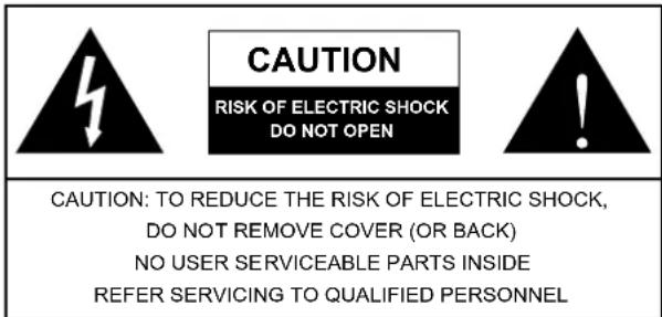
The lightning flash with arrowhead symbol, within an equilateral triangle, is intended to alert the user to the presence of uninsulated "dangerous voltage" within the product's enclosure that may be of sufficient magnitude to constitute a risk of electric shock to persons

The exclamation point within an equilateral triangle is intended to alert the user to the presence of important operating and maintenance (servicing) instructions in the literature accompanying the appliance
WARNING: To reduce the risk of fire or electric shock, do not expose this apparatus to rain or moisture.
CAUTION: Use of controls or adjustments or performance of procedures other than those specified may result in hazardous radiation exposure.

XP 600/1000/2000/3000/3100
POWER AMPLIFIER
USER'S MANUAL
TABLE OF CONTENTS
INTRODUCTION....4
FEATURES......4
INSTALLATION....5
FRONT PANEL DESCRIPTION....6
REAR PANEL DESCRIPTION....8
DIMENSIONS....10
SPECIFICATIONS....11
SYSTEM BLOCK DIAGRAM....13
APPENDIX....14
SERVICE REQUEST FORM....15
INTRODUCTION
Thank you for choosing XP series power amplifier. The unit is designed to provide a good combination of power, audio clarity, reliability and durability. An efficient heat-dissipation system comprising a high-surface area heat sink coupled with two variable speed fans ensures quiet and reliable cooling. Good sound quality and sturdy construction make this unit ideal for a multitude of amplification tasks; from studio installations to mobile DJs, house of worship and touring bands. In order to get the best performance out of your XP series power amplifier, please read this user manual carefully, and retain it for future reference.
FEATURES
e- Advanced powerful performance- third generation circuitry design
- High continuous current output from robust toroidel transformer
- Switchable input peak limiter and selectable high pass filter(30 Hz, 50 Hz) to reduce distortion and protect speakers
- Front mounted 2 low pass filters (XP2100 and XP3100 only) and 2 gain-controls
- Selectable stereo, parallel & bridge mono amp modes
● Ground Lift-switch against humming
- Signal level at -40, -20, -10, protect and clip LED indicators to monitor performance
- Bridge mono and parallel mode LEDs
- Detented gain controls
- Fast Recovery design for lower distortion if clipping occurs
● Active balanced inputs for low noise
- XLR/TRS connectors for maximum input flexibility
● Speakon and 5-way binding post speaker outputs
- 2 ventilation variable speed fans
- Very rugged housing
- fits a standard 19" rack
INSTALLATION
MOUNTING
The power amplifier can be installed in a standard 19-inch equipment rack. It requires 3 units (5.25 inches) for the XP 2000/2100, XP 3000/3100, and 2 units (3.5 inches) for the XP600/1000 of vertical rack space and secures to the rack cabinet with four rack mount screws and cup washers. In a rack, it is best to mount units one above the other, with at least a unit of space at least between two amplifiers. This provides efficient airflow and support.
COOLING
Two variable-speed fans would start running as soon as the power is being turned on. Before mounting your amplifier, you should familiarize yourself with its cooling requirements.
The air flows from the front to the back, so it is important not to block the amplifier front air vents. If the amplifier is rack-mounted, leave some space in front of the rack to prevent heated air being drawn back into the front-to-back airflow.
Airflow restrictions are the most common cause of inadequate cooling. They may result from improper mounting, bundles of power cords, clogged dust filters and closed rack doors. Mount the amplifier to allow sufficient airflow out the front outlets to ensure your amplifier work properly.
WIRING
The balanced XLR and TRS input connectors will accept the line-level output of most devices for ultimate input convenience. The amplifier built-in XLR and TRS connectors can be wired similarly for balanced or unbalanced, floating or ground-referenced sources. The output connector is a binding post with Speakon which provides an easy connection when using banana plugs, spade lugs or bare wires.
INPUT WIRING
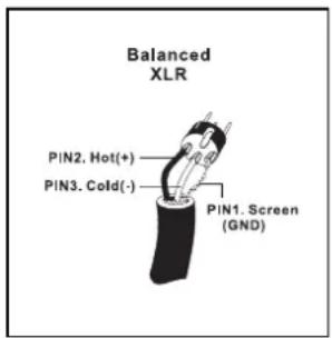
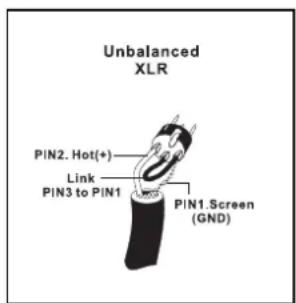
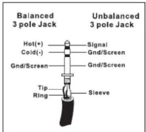
OUTPUT WIRING
SPEAKON PIN OUT
CH1
| PIN | INCH | CH | |
| 1+ | 1 | 2+ | 2 |
| 1- | 1 | 2- | 2 |
| 1+ | BRG+ | BRG- |
CH2
| PIN | INCH | CH | |
| 1+ | 2 | 2+ | NA |
| 1- | 2 | 2- | NA |
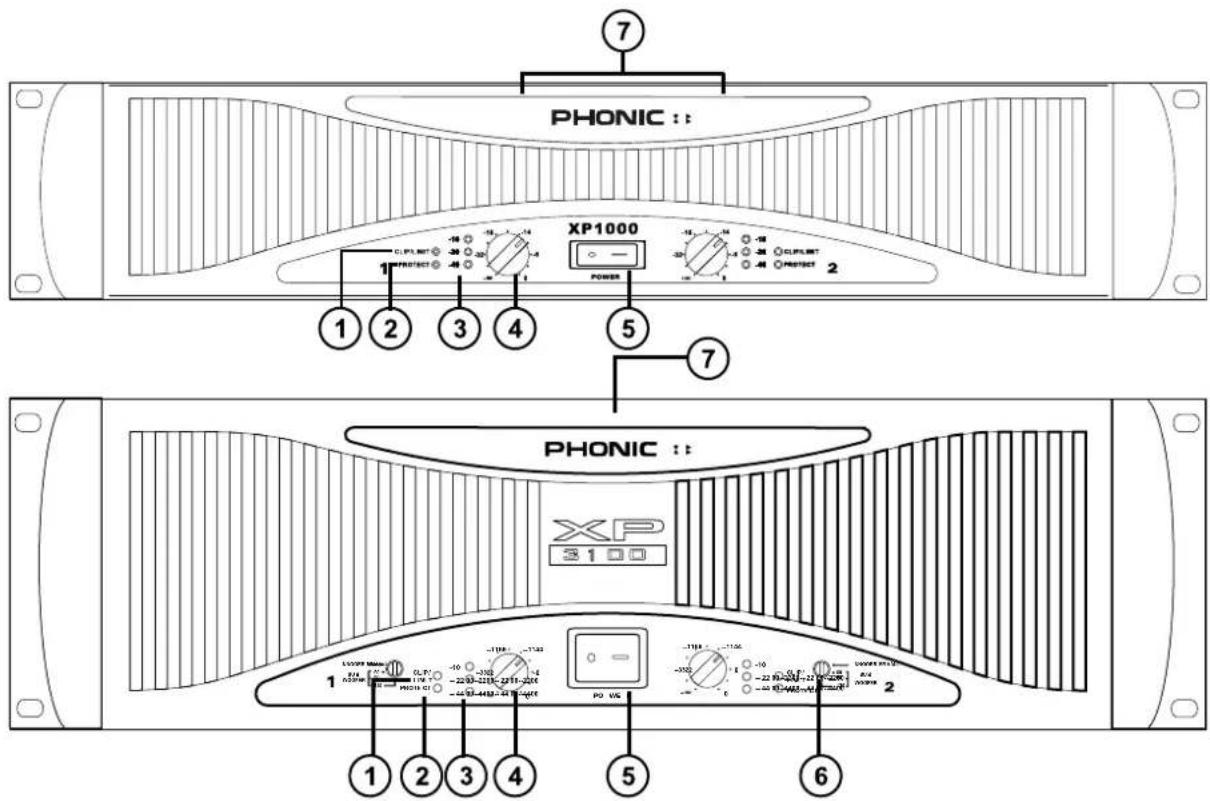
FRONT PANEL DESCRIPTION
1 CLIP/LIM LED (RED)
When the audio signal drives the amplifier output circuit beyond its power capability, it will clip. The peak limiter detects this and quickly reduces the gain to minimize the amount of overdrive, so as to preserve as much of the program dynamics as possible.
2 PROTECT LED (YELLOW)
The power amplifier features several types of protection to prevent damage to the circuitry during turn-on or fault conditions. The power-on protection relay prevents damaging thumps to the speakers as the power comes on. When the amplifier is switched on, the protect LED will light for a few seconds, and then go out, indicating that the relay has closed, connecting the speakers to the amplifier.
The protect LED will also come on if the speaker terminals are short circuited, or the impedance of the load between them is too low. Under these circumstances, the protect LED will stay on until the fault condition is rectified.
If the amplifier's large heat sinks go down for thermal reasons, leave the power connected to the amplifier, try to improve ventilation, and reduce the gain. Without power, the fan cannot operate, and the amplifier will require longer to reach a low enough temperature to restart.
3 SIGNAL LED (GREEN)
rEach channel of the power amplifier features a signal light to show that how much of an audio signal has been put in to the channel. The threshold for the indicator is -40dB, above that, noise will trigger the LED to light.
4 GAIN CONTROL
6 SUBWOOFER SWITCH (XP2100/3100 ONLY)
These two knobs are the level controls for each chan-NORMAL/60/90/120Hz
nel of the amplifier. The gain increases as the knob is turned clockwise. This unit features detented gain controls.
5 POWER SWITCH
Although the XP series amplifiers feature power-on muting, it is always a good practice to reduce both the gain controls before turning on the amplifier. The powering-up procedure for an audio system should start from instruments and then mixer, and you should verify that all system operations are normal before turning on the amplifier.
Switching from normal to either 60Hz, 90Hz or 120Hz setting will add the dedicated low pass filter to the output path, which offers you a sub bass output to achieve a 3-way or more ways speaker system. When you activate this function, you will get the subwoofer frequency output below 60Hz, 90Hz or 120Hz only.
7 DISPLAY
When the power is on, the PHONIC logo at the top of the front panel will light up in green.
When the amplifier is switched to the bridge mono mode, the bridge LED right next to the PHONIC logo will light up in red.
When the amplifier is switched to the parallel mode, the parallel LED next to the bridge LED will light up in yellow.
flowchart
graph TD
    subgraph INPUT Module
        A["+TIP / PIN2"] --> B["CH 2"]
        C["-RING / PIN3"] --> D["CH 1"]
        E["SLEEVE / PIN1"] --> F["CH 2"]
        G["PARALLEL STEREO BRIDGE"] --> H["MODE"]
        I["LOADING"] --> J["MODE"]
    end

    subgraph OUTPUT Module
        K["MIN REQUIRED LOAD OR CH 2 VAC SINs"] --> L["OUTPUT CH 2 CH 1"]
        M["MIN REQUIRED LOAD OR CH 1 VAC SINs"] --> N["OUTPUT CH 2 CH 1"]
        O["MIN REQUIRED LOAD OR CH 0 VAC SINs"] --> P["OUTPUT CH 2 CH 1"]
    end

    subgraph MODE Module
        Q["LIMITER ON/OFF"] --> R["MODE"]
        S["OFF/STEREO BRIDGE"] --> T["MODE"]
        U["PERIATION ON/OFF"] --> V["MODE"]
    end

    style INPUT Module fill:#f9f,stroke:#333
    style OUTPUT Module fill:#ccf,stroke:#333
    style MODE Module fill:#cfc,stroke:#333
    style OUTPUT CH 2 CH 1 fill:#fff,stroke:#333
    style OUTPUT CH 2 CH 1 fill:#fff,stroke:#333
    style MODE CH 2 CH 1 fill:#fff,stroke:#333
REAR PANEL DESCRIPTION
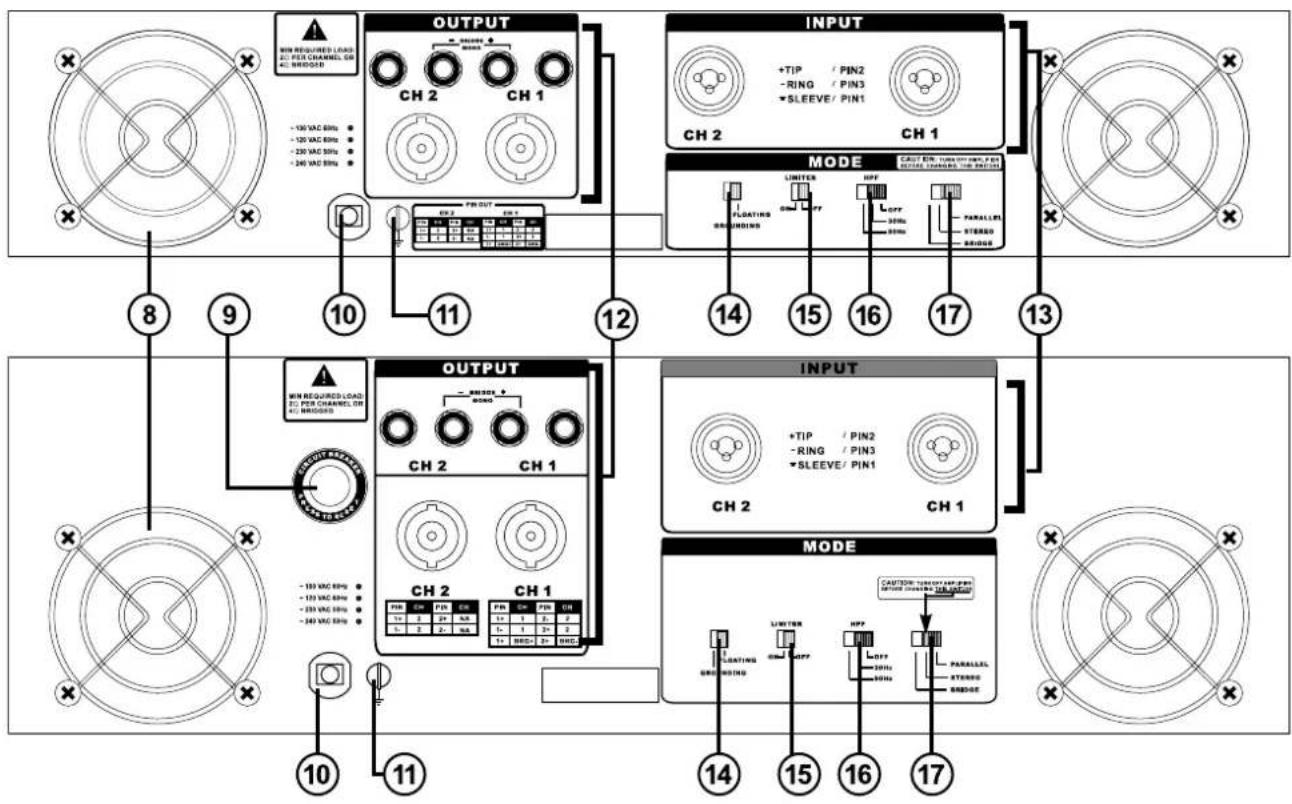
8 FAN
These two variable speed fans automatically maintain safe internal temperature. Keep the front and rear ver clear to allow full airflow. Hot air will be drawn out the back of the amplifier, so it does not stay in the rack, and make sure plenty of cool air can enter the rack.
9 RESET BREAKER (XP2000/2100 & XP 3000 /3100 ONLY)
With rated loads and output levels, the breaker should only shut down the amplifier in rare instances of catastrophic failure. The circuit breaker can also shut down the amplifier in cases where extremely low-impedance loads and high output levels result in a current draw that exceeds its rating.
10 POWER CORD
All units are shipped with an appropriate plug and cord for the required AC voltage. This product is equipped with a 3-wire grounding type plug. This is a safety feature and should not be defeated. Check the AC voltage before connecting the plug.
11 CHASSIS GROUNDING CONNECTING POINT
Please refer to your local safety code for proper grounding.
12 OUTPUT CONNECTORS
A pair of versatile binding posts and Speakon connectors are provided for output connection to each channel. Loudspeakers can be easily connected using banana plugs, spade lugs, bare wires or Speakon connector. Spade lugs and bare wires should both be screwed down tightly to avoid a short circuit. The Speakon connector for channel 1 includes channel 1, channel2 and bridged mono pin connecting points. A pin out information could be foundbeside the Speakon connector.
13 INPUT CONNECTORS
The power amplifier offers XLR and TRS input connectors for your connecting convenience.
14 GROUNDING - FLOATING SWITCH
This switch allows the circuit and chassis grounding to be separated in case of a grounding conflict. In normal use, the switch should be in the grounding on position. Lifting the grounding (to what is called the floating position) may resolve the ground conflict, but it means that circuit grounding depends on other connected equipment. Deficiencies in other components' grounding will affect the sound quality and cause a grounding loop hum. For the best combination of safety and performance, it is highly recommended to set the switch at the "grounding on" position.
15 LIMITER ON/OFF
This switch allows you to route the peak limiter circuit to the input signal. This function will reduce distortion and protect speakers.
16 HPF
This switch can activate a 30Hz or 50Hz high pass filter, which will roll off signals below either 30 Hz or 50 Hz. This improves sub bass performance by limiting sub bass cone motion. It will make more power available for the speakers' rated frequency range.
17 PARALLEL / STEREO / BRIDGE MONO SWITCH
Turn off the power before changing the operation mode. In stereo operation, each channel of the amplifier runs independently with its own signal and speakers. When the switch is set to the parallel mode, the input of CH2 is paralleled with that of CH1. Then, CH1 and CH2 can drive their own speakers independently, but they will have the same source, that of CH1. In bridge mono operation, both channels can be configured to drive a single load with a single signal at twice the power. Use the following procedure to ensure the systems safety when switching from one mode to another:
- Turn off the power of the amplifier
- Put one speaker, of not less than 4 ohms impedance, across the red (+) output terminals of the amplifier.
- Ensure that there is only one input signal connected to CH1.
- Switch the amplifier to bridge mono.
- Turn the gain controls of CH1 and CH2 to the extreme left and then turn on the amplifier.
- Verify operation at low gain, and then turn up the CH1 gain to increase power to a desired level.
DIMENSIONS
XP2000/2100/3000/3100
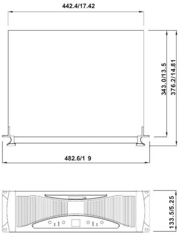
XP600/100 0
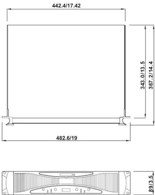
Measurements are shown in mm/inch.
SPECIFICATIONS
| SPECIFICATIONS XP 600 XP | 1000 XP | 2000 / XP | 2100 XP 3000 | XP 3100 |
| Stereo Mode (driving both channels) Continuous Average Output Power Per Channel | ||||
| 8Ω 20Hz-20KHz 0.03% THD 125W | 250W 400W | 600W | ||
| 4Ω 20Hz-20KHz 0.05% THD 200W | 00W 600W | 1000W | ||
| 8Ω EIA 1KHz 1% THD | 140W | 275W | 450W | 650W |
| 4Ω EIA 1KHz 1% THD | 220W | 440W | 660W | 1100W |
| 2Ω EIA 1KHz 1% THD | 280W | 560W | 960W | 1400W |
| Bridge Mono Mode | Continuous Average Output Power | |||
| 8Ω 20Hz-20KHz 0.1% THD | 400W | 800W | 1200W | 2000W |
| 4Ω 1KHz 1% THD | 560W | 1120W | 1920W | 2800W |
| All Models | ||||
| Input sensitivity @ 8 | 1Vrms | 1.4Vrms | 1.73Vrms | |
| Input sensitivity @ 4Ω | 0.9Vrms | 1.25Vrms | 1.23Vrms | 1.58Vrms |
| Noise(unweighted 20Hz-20KHz below rated output) | 106dB | 107dB | ||
| Distortion(SMPTE-IM) | <0.01% | <0.02% | ||
| Damping Factor | >200 @ 8Ω | >500 @ 8Ω | ||
| Output Circuitry | Class HAmplifier | |||
| Filtering | High pass filter (30Hz, 50Hz) | |||
| Subwoofer output | Selectable subwoofer crossover at 60Hz, 90Hz, 120Hz for subwoofer output (XP 2100, XP 3100 only) | |||
| Frequency Response | 20Hz-20KHz, 0/-1dB, -3dB points: 5Hz-100KHz | |||
| Input Impedance | 20 KΩ balanced, 10 KΩ unbalanced | |||
| Cooling | Dual continuous variable-speed fans, front-to-rear air flow | |||
| Connectors (each channel) | Input: XLR & 1/4" TRS jacks Output: Speakon & binding posts | |||
| Indicators | Power: Amber Phonic logo; Parallel: Green backlight icon; Bridged: Red backlight icon CLIP/LIM: Red LED; PROTECT: Yellow LED Green LED for -10dB, -20dB and -40dB Signal Lights | |||
| Front panel controls | CH1 & CH2 GAIN knobs with 41 detents; Selectable low frequency crossover at 60Hz, 90Hz and 120Hz (XP 2100 and XP 3100 only) | |||
| SPECIFICATIONS XP 600 XP | 1000 XP 2000 / XP2100 | XP 3000 / XP | 3100 | |
| Amplifier Protection | Short circuit, thermal, subsonic, RF protection, Output DC offset,Heatsink and transformer over-heat protection, Power on/off muting,Soft start power on | |||
| Gain | 32x (30dB) | 40x (32dB) | ||
| Power Consumption 150W 293W 880 W 1460W | ||||
| Dimensions (WxHxD) | 482.6 x 89 x 367.2mm19" x 3.5" x 14.4" | 482.6 x 133.5 x 376mm19" x 5.25" x 14.8" | ||
| Weight | 15kg (33lbs) | 16kg (35.2lbs) | 21kg (46.3lbs) | 23.3kg (51.3lbs) |
SYSTEM BLOCK DIAGRAMS
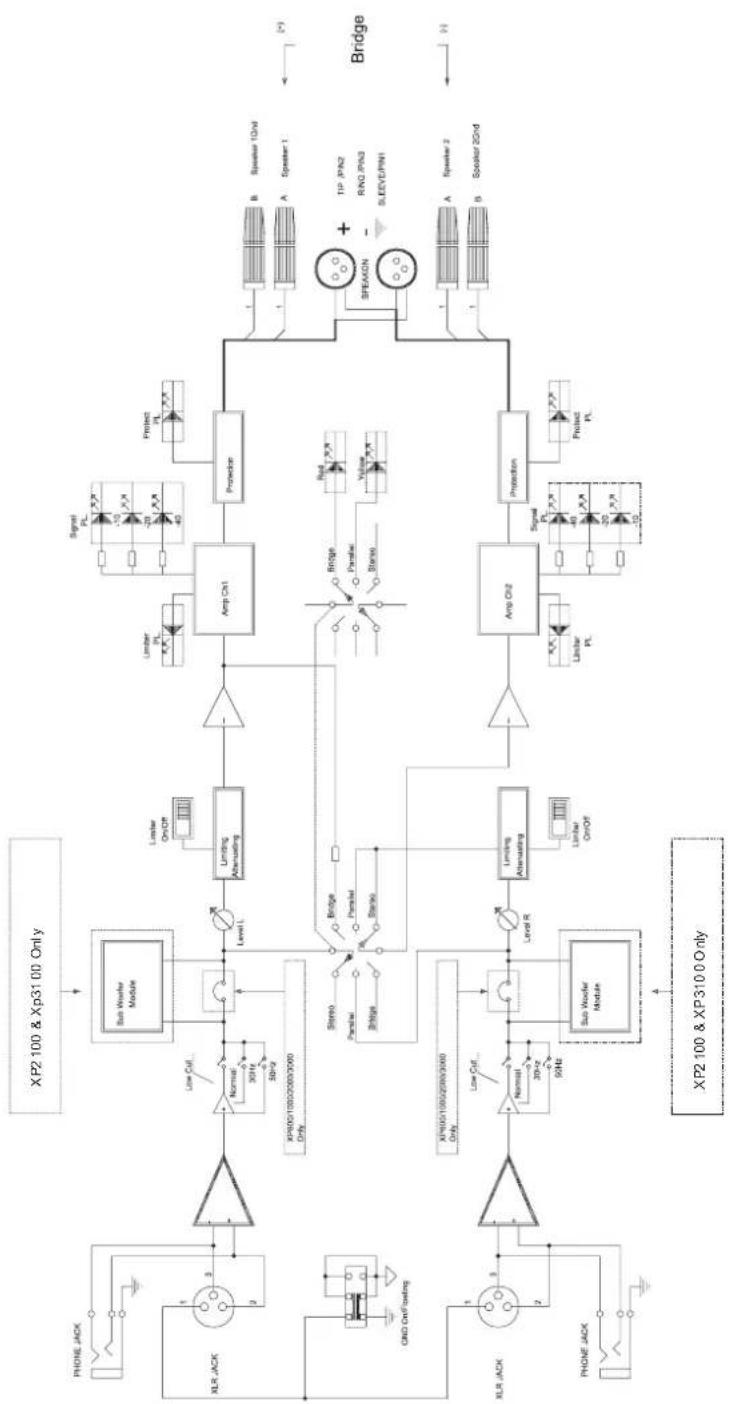
flowchart
graph TD
    A["XP2 100 & Xp31 00 Only"] --> B["Sub Worder Module"]
    B --> C["Limiting Alternating"]
    C --> D["Ampl Ch1"]
    D --> E["Protection"]
    E --> F["B: Speaker 10nd"]
    E --> G["A: Speaker 1"]
    E --> H["SPEAMON"]
    H --> I["TIP JPN2"]
    H --> J["RNO JPN3"]
    H --> K["SLEEVE/PIN1"]
    L["XP60G/100/200/3000 Only"] --> M["Low Cut"]
    N["XP60G/100/250/3000 Only"] --> O["Low Cut"]
    P["XP60G/100/250/3000 Only"] --> Q["Low Cut"]
    R["XP60G/100/250/3000 Only"] --> S["Low Cut"]
    T["XP60G/100/250/3000 Only"] --> U["Low Cut"]
    V["XP60G/100/250/3000 Only"] --> W["Low Cut"]
    X["XP60G/100/250/3000 Only"] --> Y["Low Cut"]
    Z["XP60G/100/250/3000 Only"] --> AA["Low Cut"]
    AB["XLR JACK"] --> AC["Ground"]
    AD["XLR JACK"] --> AE["Ground"]
    AF["XLR JACK"] --> AG["Ground"]
    AH["XLR JACK"] --> AI["Ground"]
    AJ["XLR JACK"] --> AK["Ground"]
    AL["XLR JACK"] --> AM["Ground"]
    AN["XLR JACK"] --> AO["Ground"]
    AP["XLR JACK"] --> AQ["Ground"]
    AR["XLR JACK"] --> AS["Ground"]
    AT["XLR JACK"] --> AU["Ground"]
    AV["XLR JACK"] --> AW["Ground"]
    AX["XLR JACK"] --> AY["Ground"]
    AZ["XLR JACK"] --> BA["Ground"]
TO PURCHASE ADDITIONAL PHONIC GEAR AND ACCESSORIES
To purchase Phonic gear and optional accessories, contact any authorized Phonic distributor. For a list of Phonic distributors please visit our website at www.phonic.com and click on Get Gear. You may also contact Phonic directly and we will assist you in locating a distributor near you.
SERVICE AND REPAIR
Phonic has over 100 service centers worldwide. For replacement parts, service and repairs please contact the Phonic distributor in your country. Phonic does not release service manuals to consumers, and advice users to not attempt any self repairs, as doing so voids all warranties. You can locate a dealer near you at www.phonic.com.
WARRANTY INFORMATION
Phonic stands behind every product we make with a no-hassles warranty. Warranty coverage may be extended, depending on your region. Phonic Corporation warrants this product for a minimum of one year from the original date of purchase against defects in material and workmanship under use as instructed by the user's manual. Phonic, at its option, shall repair or replace the defective unit covered by this warranty. Please retain the dated sales receipt as evidence of the date of purchase. You will need it for any warranty service. No returns or repairs will be accepted without a proper RMA number (return merchandise authorization). In order to keep this warranty in effect, the product must have been handled and used as prescribed in the instructions accompanying this warranty. Any tempering of the product or attempts of self repair voids all warranty. This warranty does not cover any damage due to accident, misuse, abuse, or negligence. This warranty is valid only if the product was purchased new from an authorized Phonic dealer/distributor. For complete warranty policy information, please visit http://www.phonic.com.
CUSTOMER SERVICE AND TECHNICAL SUPPORT
We encourage you to visit our online help at http://www.phonic.com/help/. There you can find answers to frequently asked questions, tech tips, driver downloads, returns instruction and other helpful information. We make every effort to answer your questions within one business day.
Phonic America Corporation
6103 Johns Road, #7
Tampa, FL 33634
(813) 890-8872
support@phonic.com
http://www.phonic.com
PHONIC
PHONIC
WWW.PHONIC.COM
- IMPORTANT SAFETY INSTRUCTIONS
- XP 600/1000/2000/3000/3100
- POWER AMPLIFIER
- USER'S MANUAL
- TABLE OF CONTENTS
- INTRODUCTION
- FEATURES
- INSTALLATION
- MOUNTING
- COOLING
- WIRING
- OUTPUT WIRING
- SPEAKON PIN OUT
- FRONT PANEL DESCRIPTION
- CLIP/LIM LED (RED)
- PROTECT LED (YELLOW)
- SIGNAL LED (GREEN)
- GAIN CONTROL
- SUBWOOFER SWITCH (XP2100/3100 ONLY)
- POWER SWITCH
- DISPLAY
- REAR PANEL DESCRIPTION
- FAN
- RESET BREAKER (XP2000/2100 & XP 3000 /3100 ONLY)
- POWER CORD
- CHASSIS GROUNDING CONNECTING POINT
- OUTPUT CONNECTORS
- INPUT CONNECTORS
- GROUNDING - FLOATING SWITCH
- LIMITER ON/OFF
- HPF
- PARALLEL / STEREO / BRIDGE MONO SWITCH
- DIMENSIONS
- SPECIFICATIONS
- SYSTEM BLOCK DIAGRAMS
- TO PURCHASE ADDITIONAL PHONIC GEAR AND ACCESSORIES
- SERVICE AND REPAIR
- WARRANTY INFORMATION
- CUSTOMER SERVICE AND TECHNICAL SUPPORT
- PHONIC
Brand : PHONIC
Model : XP 600
Category : Receiver