
MVP-WDS - Computer Accessories AMX - Free user manual and instructions
Find the device manual for free MVP-WDS AMX in PDF.


| Product Type | Computer Accessories (Video Wall Processor) |
| Brand | AMX |
| Model | MVP-WDS |
| Dimensions (W x H x D) | 17.4 x 1.7 x 8.4 inches (442 x 43 x 213 mm) |
| Weight | 5.5 lbs (2.5 kg) |
| Power Supply | 100-240 VAC, 50/60 Hz, 60W |
| Video Inputs | 4x HDMI, 2x DisplayPort |
| Video Outputs | 4x HDMI, 2x DisplayPort |
| Supported Resolutions | Up to 4K@60Hz (3840x2160) |
| Control Interface | Ethernet, RS-232, IR |
| Functionality | Video wall processing, multi-image display, scaling, bezel compensation |
| Operating Temperature | 32°F to 104°F (0°C to 40°C) |
| Storage Temperature | -4°F to 140°F (-20°C to 60°C) |
| Humidity | 10% to 90% (non-condensing) |
| Included Accessories | Power cord, rack ears, user manual |
| Maintenance | Clean with a soft, dry cloth. Do not use liquid cleaners. |
| Safety Precautions | Keep away from liquids and excessive heat. Use only in a well-ventilated area. |
| Spare Parts | Contact AMX customer service for replacement parts. |
| Reparability | Repairs should be performed by qualified service personnel only. |
| General Information | Professional-grade video wall processor for commercial installations. |
Frequently Asked Questions - MVP-WDS AMX
User questions about MVP-WDS AMX
0 question about this device. Answer the ones you know or ask your own.
Ask a new question about this device
Download the instructions for your Computer Accessories in PDF format for free! Find your manual MVP-WDS - AMX and take your electronic device back in hand. On this page are published all the documents necessary for the use of your device. MVP-WDS by AMX.
USER MANUAL MVP-WDS AMX
Wall Docking Station
for MVP-7500/8400 Modero® ViewPoint® Wireless Touch Panels
AMX Limited Warranty and Disclaimer
AMX warrants its products to be free of defects in material and workmanship under normal use for three (3) years from the date of purchase from AMX, with the following exceptions:
- Electroluminescent and LCD Control Panels are warranted for three (3) years, except for the display and touch overlay components that are warranted for a period of one (1) year.
- Disk drive mechanisms, pan/tilt heads, power supplies, and MX Series products are warranted for a period of one (1) year.
- AMX Lighting products are guaranteed to switch on and off any load that is properly connected to our lighting products, as long as the AMX Lighting products are under warranty. AMX does guarantee the control of dimmable loads that are properly connected to our lighting products. The dimming performance or quality cannot be guaranteed due to the random combinations of dimmers, lamps and ballasts or transformers.
- Unless otherwise specified, OEM and custom products are warranted for a period of one (1) year.
- AMX Software is warranted for a period of ninety (90) days.
- Batteries and incandescent lamps are not covered under the warranty.
This warranty extends only to products purchased directly from AMX or an Authorized AMX Dealer.
All products returned to AMX require a Return Material Authorization (RMA) number. The RMA number is obtained from the AMX RMA Department. The RMA number must be clearly marked on the outside of each box. The RMA is valid for a 30-day period. After the 30-day period the RMA will be cancelled. Any shipments received not consistent with the RMA, or after the RMA is cancelled, will be refused. AMX is not responsible for products returned without a valid RMA number.
AMX is not liable for any damages caused by its products or for the failure of its products to perform. This includes any lost profits, lost savings, incidental damages, or consequential damages. AMX is not liable for any claim made by a third party or by an AMX Dealer for a third party.
This limitation of liability applies whether damages are sought, or a claim is made, under this warranty or as a tort claim (including negligence and strict product liability), a contract claim, or any other claim. This limitation of liability cannot be waived or amended by any person. This limitation of liability will be effective even if AMX or an authorized representative of AMX has been advised of the possibility of any such damages. This limitation of liability, however, will not apply to claims for personal injury.
Some states do not allow a limitation of how long an implied warranty last. Some states do not allow the limitation or exclusion of incidental or consequential damages for consumer products. In such states, the limitation or exclusion of the Limited Warranty may not apply. This Limited Warranty gives the owner specific legal rights. The owner may also have other rights that vary from state to state. The owner is advised to consult applicable state laws for full determination of rights.
EXCEPT AS EXPRESSLY SET FORTH IN THIS WARRANTY, AMX MAKES NO OTHER WARRANTIES, EXPRESSED OR IMPLIED, INCLUDING ANY IMPLIED WARRANTIES OF MERCHANTABILITY OR FITNESS FOR A PARTICULAR PURPOSE. AMX EXPRESSLY DISCLAIMS ALL WARRANTIES NOT STATED IN THIS LIMITED WARRANTY. ANY IMPLIED WARRANTIES THAT MAY BE IMPOSED BY LAW ARE LIMITED TO THE TERMS OF THIS LIMITED WARRANTY.
FCC Information
This device complies with Part 15 of the FCC Rules. Operation is subject to the following two conditions: (1) this device may not cause harmful interference, and (2) this device must accept any interference received; including interference that may cause undesired operation.
Federal Communications Commission (FCC) Statement
This equipment has been tested and found to comply with the limits for a Class B digital device, pursuant to Part 15 of the FCC rules. These limits are designed to provide reasonable protection against harmful interference in a residential installation. This equipment generates, uses and can radiate radio frequency energy, and, if not installed and used in accordance with the instructions, may cause harmful interference to radio communications. However, there is no guarantee that interference will not occur in a particular installation. If this equipment does cause harmful interference to radio or television reception, which can be determined by turning the equipment off and on, the user is encouraged to try to correct the interference by one or more of the following measures:
- Reorient or relocate the receiving antenna.
- Increase the separation between the equipment and receiver.
- Connect the equipment into an outlet on a circuit different from that to which the receiver is connected.
- Consult the dealer or an experienced radio/TV technician for help.
FCC RF Radiation Exposure Statement
This transmitter must not be co-located or operating in conjunction with any other antenna or transmitter. This equipment complies with FCC RF radiation exposure limits set forth for an uncontrolled environment. This equipment should be installed an operated with a minimum distance of 20 centimeters between the radiator and your body.
Table of Contents
MVP-WDS Wall Docking Station & CB-MVPWDS Rough-In Box 1
Overview 1
Specifications 2
MVP-WDS docking station connector locations 3
LED Indicators 3
Installation 4
Installing the CB-MVPWDS Rough-In Box 4
Removing the MVP-WDS Faceplate 5
Installing the MVP-WDS in a CB-MVPWDS Rough-In Box.... 8
Installing the MVP-WDS Using Expansion Clips 9
Installing the MVP-WDS Into a Flat Surface Using Mounting Screws 11
Replacing the Faceplate on the MVP-WDS 13
Connecting a Power Supply.... 14
Powering the MVP-WDS 14
Using the 3.5mm mini-Phoenix Connector for Power 14
Connecting and Using USB Input Devices on the Stations 15
Interface Connector Pins and Functions 15
Securing an MVP Panel to an MVP-WDS.... 16
Removing an MVP Panel from an MVP-WDS 17
Unsecured MVP removal from an MVP-WDS 17
Secured MVP removal from an MVP-WDS 17
Undock-
Installing and Charging Batteries in the Docking Stations 18
Installing MVP-BP Batteries Into the MVP-WDS 18
Installing the MVP-WDS-SK Silver Conversion Kit.... 19
Removing the original faceplate 19
Removing the existing black pivot unit (battery and cradle combo) 21
Installing the new conversion kit's pivot unit components.... 23
Installing the new silver faceplate 24
Upgrading the Docking Station Firmware 27
Step 1: Prepare the Docking Station for firmware transfer via USB.... 27
Step 2: Upgrade the Docking Station firmware via USB 28
Table of Contents
MVP-WDS Wall Docking Station & CB-MVPWDS Rough-In Box
Overview
The MVP-WDS Wall/Flush Mount Docking Station (FIG. 1) provides a surface-installed docking location. MVP-WDS stations use a security latch to secure the panel to the docking station for MVP panels, and come in 2 faceplate colors; black (FG5965-11) and silver (FG5965-21).
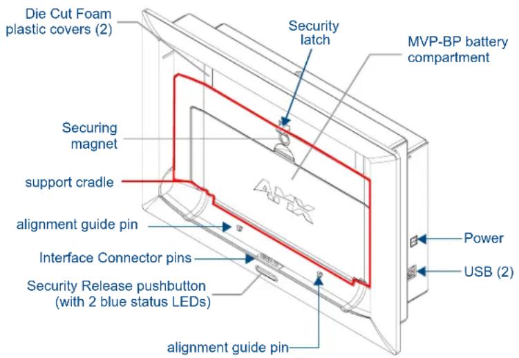
FIG. 1 MVP-WDS Docking Station components

The faceplate must be removed prior to any installation of the WDS into a surface or CB-MVPWDS rough-in box. The two Die Cut Foam covers are then placed over the two #6-32 faceplate security screws, post installation.
- The Security Release pushbutton raises the security latch for easy removal of the MVP panel. The securing magnet is used to keep the MVP panel from falling out of the cradle when the MVP is angled forward.

A security code (password) can be enabled via the Protected Password page. This feature requires that the code must be entered on the panel before it can be removed from the docking station.
- One or two (optional) MVP-BP batteries can be recharged from either of the two rear compartments on the MVP-WDS (or from within the MVP panel).
- Attach a keyboard or mouse using the docking station's side USB ports. This connection facilitates surfing the Web via the G4 Computer Control application.
- Another key feature of the MVP-WDS is that it can be mounted into either a solid surface (using surface screws) or into an optional CB-MVPWDS rough-in box (for pre-wall installation). These two installation options allow the MVP to be mounted into virtually any surface environment. Refer to the Installation section on page 4 for more information.
Specifications
| MVP-WDS Specifications | |
| Dimensions (HWD): | 8.59" x 12.66" x 3.40" (21.82 cm x 32.16 cm x 8.64 cm)Note: Always use the cutout/installation dimensions for the MVP-WDS when installing this unit into various surfaces. This SP engineering drawing is available online at www.amx.com. Refer to the Installation section on page 4 for details. |
| Power Requirements: • Stand-alone with no batteries: 0.1 A @ 12 VDCStand-alone charging two batteries: 2.1 A @ 12 VDCWith no batteries and charging a connected MVP panel's two internal batteries: 3.3 A @ 12 VDCWith two batteries and charging a connected MVP panel's two internal batteries: 3.3 A @ 12 VDC | |
| Weight: • Stand-alone: 4.67 lbs (1.89 kg)With two batteries: 5.47 lbs (2.48 kg) | |
| Available Colors: • MVP-WDS (Black) - FG5965-11MVP-WDS (Silver) - FG5965-21 | |
| Charging Features: • Two Battery Bays: Simultaneous ChargingCharge time for two depleted batteries ~ 5 hours | |
| Front Panel Components: • Securing MagnetSecurity Latch: Adds the primary layer of security when mounting the MVP. When the MVP is inserted, this latch grabs onto the rear of the MVP and secures it from being removed.Interface Connector Pins: A set of retractable pins (male) that connect to the underside MVP connector strip. This connection provides both communication and power between the MVP and the MVP-WDS.Support Cradle: This retractable mechanism supports a resting MVP panel and allows a user to either insert or remove a connected MVP panel.LEDs: Two blue LEDs indicate either:- Left LED monitors the battery status within either the MVP-WDS or MVP- Right LED monitors communication between the MVP-WDS and MVP.Security Release pushbutton: Located on the front of the unit, this pushbutton toggles an on-screen security keypad (if security is enabled).- Entering the correct release code allows the MVP-WDS to release the MVP from the security latch.Battery Compartment: Houses up to two MVP-BP batteries. | |
| Side Panel Components: • Host USB Connectors: Two type A USB ports connect an external keyboard and mouse device for use with the G4 Computer Control application.Power Connector: 2-pin 3.5 mm mini-Phoenix (male) connector. | |
| Operating/Storage Environments: | Operating Temperature: 0°C (32°F) to 40°C (104°F)Operating Humidity: 20% - 85% RHStorage Temperature: -20°C (-4°F) to 60°C (140°F)Storage Humidity: 5% - 85% RH |
| Included Accessories: | Installation Kit (KA2250-01):- One 2-pin 3.5 mm mini-Phoenix connector (41-5025)- One strip containing two plastic Die Cut Foam covers (60-5965-47)- Two #6-32 Faceplate Securing screws (80-0193-01)- Four Phillips-head screws (#4-32 x 0.250 Black) (80-0112)- Four Drywall clips (62-5924-05) and #6 -metal strips (80-0192) |
| MVP-WDS Specifications (Cont.) | |
| Other AMX Equipment: | CB-MVPWDS Rough-In Box (FG037-10)MVP-WDS-SK Silver Conversion Kit for MVP-WDS (FG5965-22):- One Silver Cradle Bezel/Faceplate (60-5965-20SL)- One Silver Cradle Pivot (60-5965-21SL)- One Silver Battery Cover (60-5965-22SL)- One securing rare earth magnet (63-5965-02)- One securing magnet cup (63-5965-03)- One #4-20 Magnet Securing screw (80-0193-01)- Two plastic Die Cut Foam covers (60-5965-47) |
MVP-WDS docking station connector locations
FIG. 2 shows the layout of the connectors on the right side of the MVP-WDS.
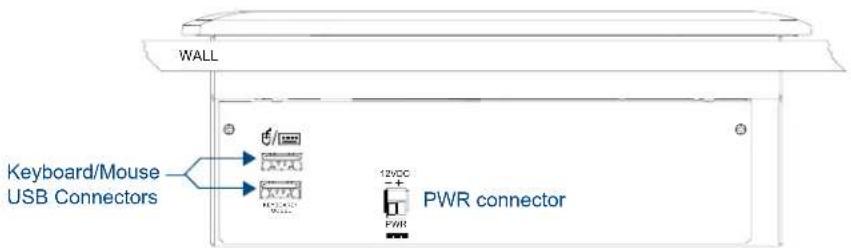
FIG. 2 Connector layout on the side of the MVP-WDS
LED Indicators
The two LEDs located within the security release pushbutton on the front panel (FIG. 1) indicate battery and communication status:
The left LED indicates activity and status for the batteries in the MVP panel and in the MVP-WDS.
The right LED indicates the docking and communication status of the docked MVP panel.
| LED Pattern Indicators for the MVP-WDS | |||
| LED Left - Battery S | status Right - Comm. Status | ||
| WDS only MVP in Cradle | |||
| Solid Bright WDS ba | teries are fully charged | MVP batteries are fully charged | MVP panel is docked and communicating |
| Flashing Bright (Slow) | WDS batteries are charging MV | batteries are charging | N/A |
| Flashing Bright (Fast) | N/A N/A MVP panel is docked but not | communicating | |
| Solid Dim WDS rece | ving power but con- tains no batteries in cradle | No batteries within the MVP | MVP panel is NOT docked and NOT communicating |
Installation
MVP-WDS wall-docking stations can be installed either the CB-MVPWDS or other solid surface environment using one of the two mounting options: drywall clips or solid surface screws, as described in the following sub-sections.
Installing the CB-MVPWDS Rough-In Box
The CB-MVPWDS (FG037-10) is a metallic rough-in box that can be secured to a stud in a pre-wall setting. The MVP-WDS can then installed into the rough-in box.

Installation procedures and configurations vary depending on the installation environment.
When mounting the rough-in box, the MVP-WDS Mounting Tabs must lie flush against the outside of the sheetrock (FIG. 3).
- Refer to installation diagram SP-5965-02 for detailed installation dimensions.
- It is recommended that you cut out the surface slightly smaller than what is outlined in the installation drawings so that you can make any necessary cutout adjustments.
-
The CB-MVPWDS can be installed with the removable access panel positioned either on top or bottom. The access panel provides convenient access to in-wall wiring and must be re-installed prior to mounting the MVP-WDS.
-
Place the left side of the rough-in box on a stud, making sure that five Stud Fastening Holes and removable Access Panel are oriented correctly (installation dependent). Be sure to leave enough of a gap between the stud and Mounting Tabs to accommodate the installation of the drywall or sheetrock after the rough-in box has been mounted. Ultimately, the Mounting Tabs should lie flush against the outside of the sheetrock (FIG. 3).
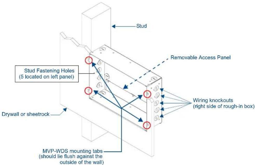
FIG. 3 CB-MVPWDS rough-in box components

NOTE
Although there are wiring knockouts are on both sides of the rough-in box, the knockouts on the right side will be used for the MVP-WDS (wall docking station) connectors, so always secure the rough-in box to the stud using the Stud Mounting Holes on the left side of the box.
- Using either nails or screws, fasten the rough-in box to the stud through the five Stud Fastening Holes.
- Remove the wiring knockouts from the right side of the rough-in box to accommodate cabling to the MVP-WDS.
- Thread the USB and Power cables through the knockouts on the right of the rough-in box. It is recommended that you test these connections before fully installing the WDS.
- Install the drywall/sheetrock before inserting the MVP-WDS into the rough-in box.
Removing the MVP-WDS Faceplate
The faceplate must be removed from the main MVP-WDS unit before any installation procedures can be done. The unit is shipped without the Die Cut Foam covers (60-5965-47) installed over the two #6-32 Faceplate Security Screws. The foam covers are installed over the faceplate screws only after the installation is complete and the support cradle is retracted.
- Place the MVP-WDS face up on a flat level surface.
- Connect the mini-Phoenix connector from a compatible 12V power supply to the PWR connector on the side panel (see FIG. 4) to apply power.
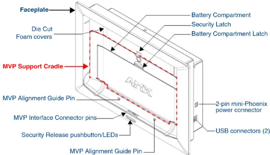
FIG. 4 MVP-WDS Docking Station components (front view)
- Open the Battery Compartment and press the Cradle Activation pushbutton (recessed white button located near the pins in Battery Slot #2) to angle the Support Cradle forward (FIG. 5).
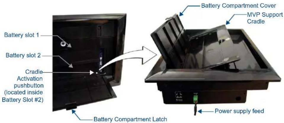
FIG. 5 Cradle activation pushbutton location and cradle angling
-
Close the battery cover and disconnect the power connector to remove power from the unit and maintain the support cradle in the forward position.
-
Remove the two #6-32 Faceplate Security Screws from the top rim of the faceplate, using a grounded Phillips-head screwdriver (FIG. 6).
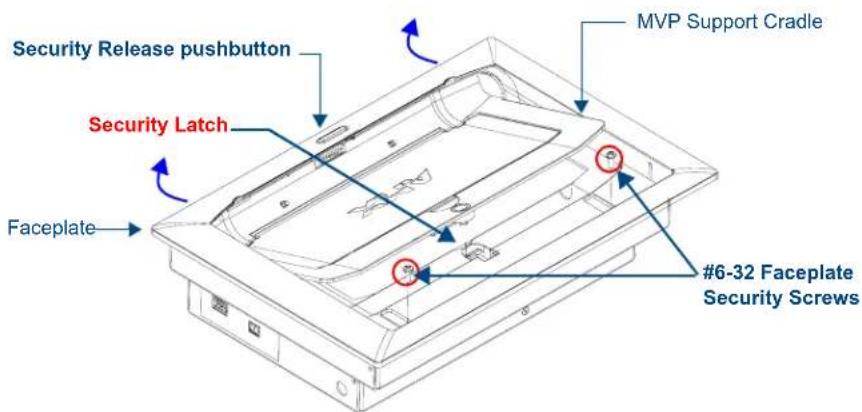
FIG. 6 Faceplate screw removal
-
Angle the top rim of the faceplate upwards, and pull it up and over the Security Latch.
-
Grab the bottom rim of the faceplate and push it up (towards the support cradle), then pull it out, sliding the four faceplate connectors out of the latches along the bottom of the WDS (FIG. 7).
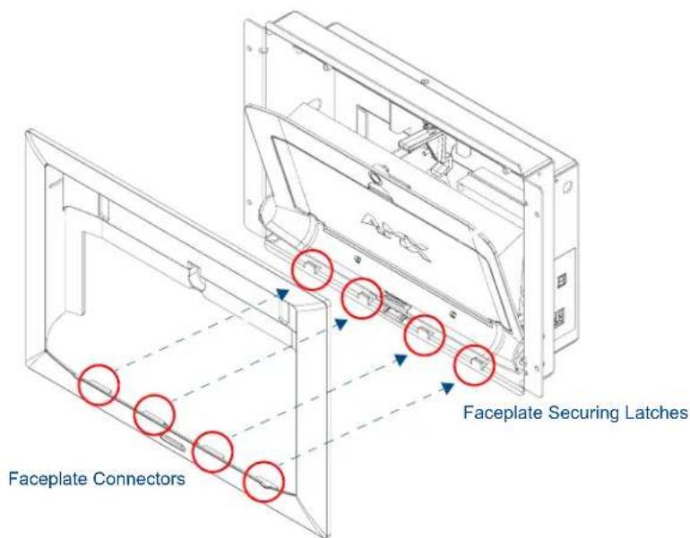
FIG. 7 Faceplate securing latch and connector locations
- Press down on the Security Latch to allow it to go through the top opening.
- Grasp the top rim of the faceplate and carefully slide it over the cradle (at an angle) until the faceplate is completely removed from the WDS (FIG. 8).
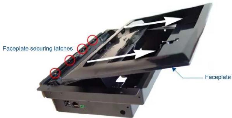
FIG. 8 Faceplate removal from MVP-WDS
Once the faceplate has been removed, you can continue the installation of the WDS.
Installing the MVP-WDS in a CB-MVPWDS Rough-In Box
- The rough-in box must be mounted prior to continuing this section. Refer to the Installing the CB-MVPWDS Rough-In Box section on page 4 for detailed pre-wall installation instructions.
- The faceplate must be removed prior to any surface installation (see the Removing the MVP-WDS Faceplate section on page 5).
-
Verify that the USB and power cables have been threaded through the knockouts on the right of the rough-in box. Leave enough slack in the wiring to accommodate re-positioning of the panel.
-
Connect the 2-pin power connector and USB cables to the WDS. The WDS must be installed with these attached. The USB connectors can be from either a USB extension cable, or a wireless USB RF transmitter.

Verify that the terminal end of the power cable is not connected to a power source before plugging in the 2-pin power connector.
- Insert the WDS into the rough-in box, so that the Mounting Tabs on the WDS lie flush against the rough-in box (FIG. 9).
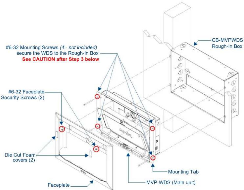
FIG. 9 MVP-WDS installation configuration within a CB-MVPWDS Rough-In Box

The MVP-WDS must be mounted on a flat surface.
- Using a grounded Phillips-head screwdriver, insert and secure four #6-32 Mounting Screws (not included) into their corresponding holes located along the sides of the MVP-WDS until the WDS is securely fastened to the rough-in box, and is flush against the wall.

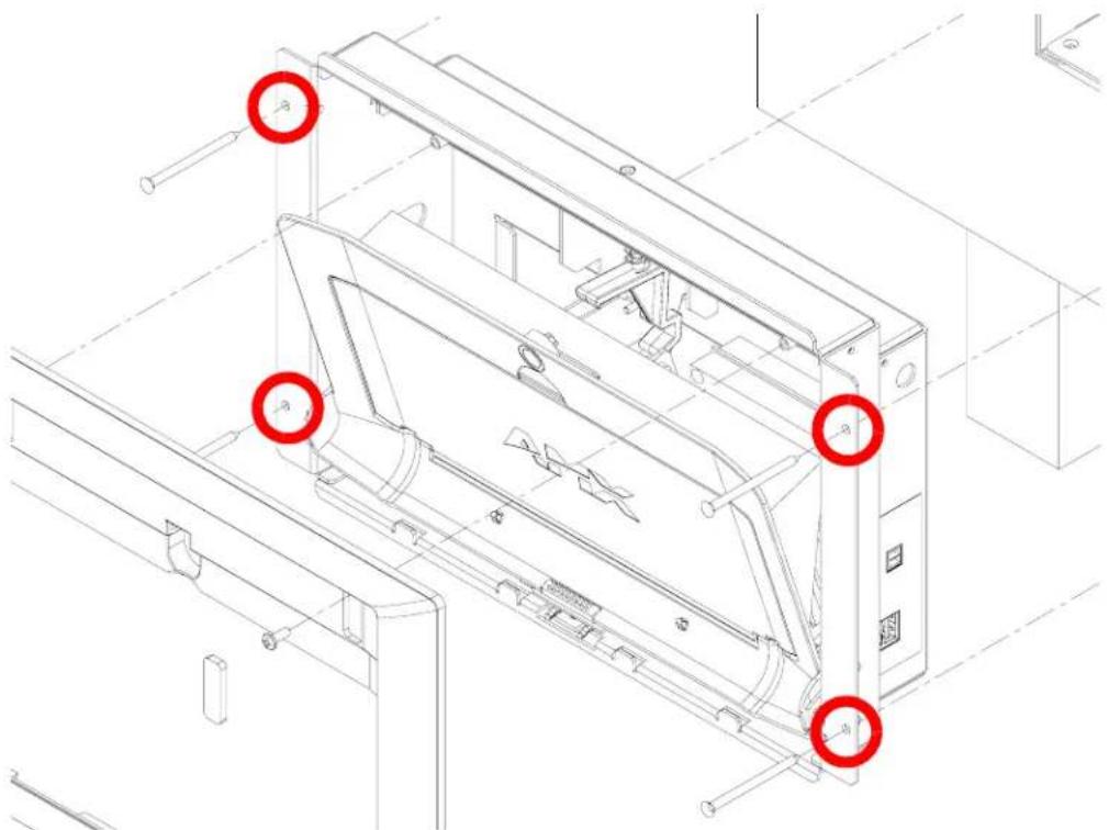
When installing the four #6-32 Mounting Screws in Step 3, turn the screwdriver gently to engage the first one or two threads of the screw and make sure that the screw is being driven straight through the holes in the Mounting Tab (FIG. 10).
If the screw is found to be entering the Mounting Tab an angle, back it out of the hole immediately and try again to avoid damaging the MVP-WDS.
natural_image
Technical line drawing of a mechanical device with red circles highlighting specific components (no text or symbols present)FIG. 10 Installing four #6-32 Mounting Screws in Step 3
- Follow the steps outlined in the Replacing the Faceplate on the MVP-WDS section on page 13 to reinstall the faceplate.
Installing the MVP-WDS Using Expansion Clips
Expansion clips are mounted through the four oval holes located along the rim of the MVP-WDS. As the screw is tightened, the clip bends toward the insertion hole and into the wall. This bending creates a "grip" on the wall by either pressing onto the wall or by securing the drywall between the housing and the drywall clip.
- The faceplate must be removed prior to any surface installation (see the Removing the MVP-WDS Faceplate section on page 5).
-
The outer frame Mounting Tabs must be flush against the mounting surface.
-
Cut out the surface for the WDS using the dimensions shown in installation diagram SP-5965-01 (reproduced in FIG. 11 on page 10). It is recommended that you cutout the surface slightly smaller than what is outlined in the installation drawings so that you can make any necessary cutout adjustments.
Be sure to cut out the four notches along the sides to accommodate the four drywall expansion clips (included).
- Thread the USB and Power cables through the surface opening, leaving enough slack in the wiring to accommodate re-positioning of the unit.
- Connect the 2-pin power connector and USB cables to the WDS. The WDS must be installed with these attached. The USB connectors can be from either a USB extension cable, or a wireless USB RF transmitter.

Verify that the terminal end of the power cable is not connected to a power source before plugging in the 2-pin power connector.
- Install the four sets of drywall screws and expansion clips into the four oval notch locations along both sides of the main unit (FIG. 12).
![12.70 [323MM] BEZEL OUTLINE 11.06 [281MM] .2S [6MM] TYP FRONT BEZEL OUTLINE 2X .52 [13MM] 1.00 [25MM] TYP R.13 [3MM] TYP 7.91 [201MM] 8.63 [219MM] BEZEL OUTLINE 4X R.13 [3MM] MAX RADIUS IN CORNERS CUTOUT 2X .22 [5MM]](/content/2026/05/773863/images/122c11076a9561af48b9dc29236bbbe8baac665891017c4c2bde21b92a48404f.jpg)
FIG. 11 MVP-WDS Wall Mount cutout dimensions using expansion clips
- Carefully insert the main unit (with expansion clips) into the cutout so that the Mounting Tabs on the MVP-WDS lie flush against the wall.
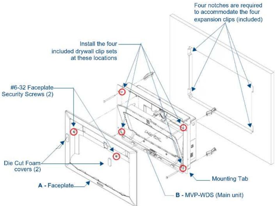
FIG. 12 MVP-WDS installation configuration for drywall surfaces

Replacement drywall clip sets cab be ordered from AMX.
- Tighten all four drywall clip sets (screws and clips) until both Mounting Tabs are securely fastened and flush against the wall.
- Follow the steps outlined in the Replacing the Faceplate on the MVP-WDS section on page 13 to angle the MVP Support Cradle forward and re-install the faceplate.
Installing the MVP-WDS Into a Flat Surface Using Mounting Screws
Use #4-40 Mounting screws (not included) to mount the WDS to a flat surface, through the two sets of holes located on the sides of the WDS.
- Refer to SP-5965-01 for detailed installation dimensions (reproduced in FIG. 13).
- It is recommended that you cutout the surface slightly smaller than what is outlined in the installation drawings so that you can make any necessary cutout adjustments.
-
The outer frame Mounting Tabs must be installed so that they are flush against the mounting surface.
-
Cut out the surface for the MVP-WDS docking station using the dimensions shown in FIG. 13.
![12.70 [323MM] BEZEL OUTLINE 52 [13MM] TYP 11.06 [281MM] FRONT BEZEL OUTLINE 1.19 [30MM] TYP R.13 [3.2MM] MAX RADIUS IN 4 CORNERS THESE 4 HOLES ARE ONLY REQUIRED WHEN MOUNTING UNIT TO A SOLID SURFACE (PODIUM, DESK, ETC), SECURE UNIT WITH #4 SCREWS CUTOUT 7.91 [201MM] 5.54 [141MM] 8.63 [219MM] BEZEL OUTLINE 12.10 [307MM]](/content/2026/05/773863/images/88f301316b2dd9a79753c32f11e99c6339899f55b2c1d69cbeec929e67bf76bf.jpg)
FIG. 13 MVP-WDS Wall Mount cutout dimensions using solid surface screws
- Thread the USB and Power cables through the surface opening, leaving enough slack in the wiring to accommodate any re-positioning of the unit.
-
Connect the 2-pin power connector and USB cables along the right side of the (un-powered) MVP-WDS. The faceplate must be removed prior to any surface installation.
-
Verify that the terminal end of the power cable is not connected to a power source before plugging in the 2-pin power connector.
- The USB connectors can be from either a USB extension cable, or a wireless USB RF transmitter.

Don't disconnect the PWR and USB connectors from the MVP-WDS. The unit must be installed with these attached.
- Test the Power and USB connections before fully installing the WDS. Refer to the LED Indicators table on page 3 for blink pattern information.

Applying power to the MVP-WDS causes the MVP Support Cradle to retract back into docking station.
- Disconnect the terminal end of the power cable from the connected power supply.
-
Carefully insert the main unit into the cutout until the Mounting Tabs on the MVP-WDS lie flush against the wall (FIG. 14).
-
Insert and secure four #4-40 Mounting Screws (not included) into their corresponding holes located along the sides of the WDS (using a grounded Phillips-head screwdriver) until the WDS is secured and is flush against the wall.
- Follow the steps outlined in the Replacing the Faceplate on the MVP-WDS section on page 13 to angle the MVP Support Cradle forward and re-install the faceplate.
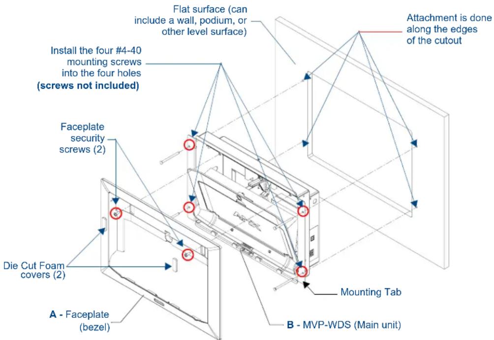
FIG. 14 MVP-WDS installation configuration for solid surfaces
Replacing the Faceplate on the MVP-WDS
- Temporarily apply power to the MVP-WDS by connecting the terminal end of the power cable to the power supply.
- Press the Cradle Activation Pushbutton (located inside the MVP-WDS battery compartment, next to the battery pins in Battery Slot #2 - see FIG. 5) to angle the Support Cradle forward.
- Temporarily remove power from the MVP-WDS to maintain the support cradle at this angle and keep it from retracting back into the MVP-WDS.
- Slide the Faceplate over the angled Support Cradle, toward the Security Release pushbutton's circuit board on the MVP-WDS (FIG. 9).
-
Gently press the faceplate down and under the Security Latch until it rests against the Mounting Tabs of the MVP-WDS main unit.
-
Be sure to snap the Faceplate Connectors back into their respective Latches (located along the bottom rim of the faceplate - see FIG. 7 on page 7).
- Verify that the Security Release Pushbutton is properly aligned over it's LEDs and circuit board on the MVP-WDS main unit.
-
Verify that the two faceplate security screw holes on both the Faceplate and the main MVP-WDS unit are properly aligned.
-
Insert and secure the two #6-32 Faceplate Security Screws into the top rim of the Faceplate using a grounded Phillips-head screwdriver.
-
Apply power to the MVP-WDS by connecting the terminal end of the power cable to the power supply.
-
Press the Cradle Activation pushbutton to cause the MVP Support Cradle to angle backwards and lie flush against the main unit.
-
Remove the two adhesive plastic Die Cut Foam covers (60-5965-47) from the strip included within the Installation Kit bag.
-
Adhere these two plastic Die Cut Foam covers into the two notches where the Faceplate Security Screws are located.
Refer to the Securing an MVP Panel to an MVP-WDS section on page 16 and Removing an MVP Panel from an MVP-WDS section on page 17.
Connecting a Power Supply
The MVP-WDS Docking Station receives power from a 12-VDC compliant power supply using a 2-pin 3.5 mm mini-Phoenix connector.

Static electricity can damage electronic circuitry. Before touching the unit, discharge any accumulated static electricity from your body by touching a grounded metal object.
Powering the MVP-WDS
The MVP-WDS uses a 12-VDC compliant power supply (not included) to provide power to the MVP panel, while charging internal batteries. Once MVP batteries are fully charged, the MVP-WDS begins charging MVP-BP batteries inserted within its battery compartments.
-
Connect the terminal end of the power supply to the rear PWR connector on the WDS.
-
Provide power to the MVP-WDS by connecting the AC power cord to an external power source.
Initially, both blue LEDs illuminate and remain dim (indicating that the power is being supplied to the MVP-WDS).
Using the 3.5mm mini-Phoenix Connector for Power
To use the 2-pin 3.5 mm mini-Phoenix connector for use with a 12 VDC-compliant power supply, the incoming PWR and GND wires from the external source must be connected to their corresponding locations on the connector (FIG. 15) to provide power to the MVP-WDS.

FIG. 15 NetLinx power connector wiring diagram
Verify that the power supply is not receiving power.
-
Insert the PWR and GND wires on the terminal end of the 2-pin 3.5mm mini-Phoenix cable. Match the wiring locations of the +/- on both the power supply and the terminal connector.
-
Tighten the clamp to secure the two wires. Do not overtighten the screws - doing so could damage the wires.
-
Verify the connection of the 2-pin 3.5 mm mini-Phoenix to the power supply, and apply power.
Connecting and Using USB Input Devices on the Stations
The MVP-WDS can have up to two USB input devices connected for use on the MVP panel's different firmware and TPD4 panel pages. These input devices can consist of a keyboard and mouse.

NOTE
USB-connected input devices are detected by the docking stations only after they are connected and then power is applied.
- Remove the power connector from the docking station.
- Insert the USB connectors of the peripheral input devices, into the appropriate USB connector on the docking station.
- Reconnect the terminal power connector to the docking station and apply power.
- Install the MVP panel onto the docking station.
- Navigate to the Protected Setup page on the MVP panel and press the Reboot button to restart the panel. This step allows the MVP panel to detect the USB input devices signals being sent through the connected docking station.

NOTE
The MVP does not recognize the keyboard and/or mouse (connected to the docking station) until after the MVP itself has been rebooted.
It does not matter if the MVP is on the docking station at the time the USB devices are plugged in or not.
The reboot of the panel has to occur after the MVP is properly connected and communicating with the docking station. In addition, if the MVP is removed from the docking station, the panel will not recognize the keyboard and/or mouse after it is put back on the docking station - the MVP will have to be rebooted again.
-
After the panel splash-screen disappears:
-
If a USB mouse has been connected, a mouse cursor appears on the panel screen and its location corresponds to the mouse cursor position sent by the external USB mouse.
- If a USB keyboard has been connected, only on-screen keyboards and keypads will reflect any external keystrokes sent from the external USB keyboard.
To be detected by the docking station, USB input devices (keyboard / mouse) must be plugged into the docking station before it is powered-up. The docking station will not detect USB input devices until the unit cycles power.
Interface Connector Pins and Functions
FIG. 16 provides the pin numbering and function information for the docking stations:
1 - Data - Panel Detect IN
2 - Ground
3 - not used
4 - Ground
5 - not used
6 - Ground
7 - not used
8 - not used
9 - not used
10 - DC Power
11 - Data - Receive
12 - DC Power
13 - Data - Transmit
14 - DC Power
15 - Data - USB Device D-
16 - Data - Cradle Detect
17 - Data - USB Device D+
18 - Data - Panel Detect OUT
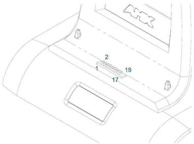
FIG. 16 MVP-TDS Connector Pin locations and Pinout function
Securing an MVP Panel to an MVP-WDS
- Place the MVP-WDS on a flat and level surface.
- Provide power to the MVP-WDS (refer to the Powering the MVP-WDS section on page 14).
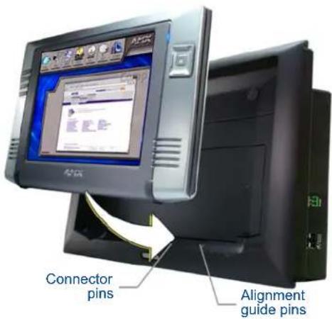
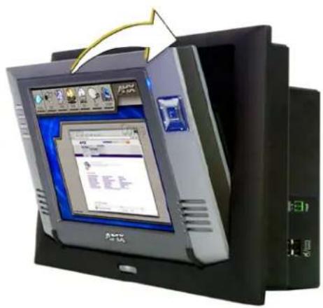
- Place the MVP on the support cradle so that the alignment pins on the WDS fit into the matching holes on the bottom of the MVP.
natural_image
Exterior view of a modern office computer with open screen and keyboard (no visible text or symbols)FIG. 17 Installing an MVP onto an MVP-WDS
-
Once proper alignment is verified, gently angle back the MVP until the rear of the panel makes contact with the electromagnet. Allow one second to activate the electromagnet.
-
When the MVP is properly docked, the following message is displayed on the panel (FIG. 18).
- Proper docking and communication can be verified via the on-screen system message, or the illuminated Docking Status button on the Protect Setup page, or the right LED on the docking station.
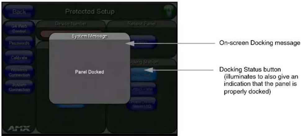
FIG. 18 System message - panel is properly docked

If the MVP is docked properly and communicating, the right LED on the MVP-WDS will remain brightly illuminated.
Refer to the LED Pattern Indicators for the MVP-WDS table on page 3 for more information.

If the panel is not securely attached, the electromagnet on the TDS will not be activated, and the panel could fall forward and be damaged.
Removing an MVP Panel from an MVP-WDS
The MVP security feature enables a security code that is entered into an on-screen password keypad. This password is configured within the MVP panel's Password Setup page.
Refer to the MVP-7500/8400 Operation/Reference Guide (available online at www.amx.com) for more information on setting up a User Access username and password.
Unsecured MVP removal from an MVP-WDS
- Press and hold the security release pushbutton.
The MVP-WDS will release the security latch from the rear of the MVP and the MVP Support Cradle will angle forward to present the MVP for removal.
- Lift the panel off the alignment guide pins and remove it from the support cradle.
- Allow the MVP-WDS one second to retract the Support Cradle.
Secured MVP removal from an MVP-WDS
- Press and hold the security release pushbutton until the on-screen keypad appears on the MVP.
- Enter the security release password.
- Press Done when finished. Allow the MVP-WDS one second to process the release request and turn off the electromagnet.
- Angle the MVP forward.
- Lift the panel off the alignment guide pins and remove it from the support cradle.
Undock- String
When the MVP is removed from the docking station (undocked), the undock-
- If the panel has no information within the User Access Passwords list, 'none' is sent as a user.
- If the undock button on the Protected Setup page is used, 'setup' is sent as a user. This string can be disabled from within the firmware setup pages.
- When the MVP is placed on a docking station (docked), the dock string is sent to a target Master. This string can be disabled from within the firmware setup pages.
Installing and Charging Batteries in the Docking Stations
The MVP-TDS and MVP-WDS Docking Stations recharge any installed MVP-BP batteries and provide USB input device interaction to the connected MVP panel through the two USB connectors on the docking stations. Both docking stations are firmware upgradeable and provide battery feedback information to the MVP (battery status information is accessible through the MVP Batteries page).
Refer to the MVP-7500/8400 Operation/Reference Guide (available online at www.amx.com) for more information on setting up a User Access username and password.

Once an MVP is connected to a docking station, charging is first applied to any MVP-BP batteries found within the panel's rear battery compartment and then to any batteries inserted within the docking station.
Installing MVP-BP Batteries Into the MVP-WDS
The MVP-WDS connects directly to a PSN4.4 power supply and provides both power and communication to docked MVP panel. The MVP-WDS can charge batteries in its own battery compartments, as well as those within the MVP panel.
- Raise the rear connector cover to expose the battery compartments and connectors.
- Slide the MVP-BP into the battery compartment (AMX label up) until the connector makes contact with the battery pins at the end of the battery slot.
- Repeat these steps for any additional MVP-BP batteries.
- The status of the connected batteries are reflected on the panel's Batteries page and the LEDs on the docking station.

The MVP-WDS top battery slot is Slot #1. The bottom battery slot is Slot #2. The recessed white cradle activation button is adjacent to Slot #2. A completely discharged battery requires 1 full charge cycle from within battery slot #1.
Installing the MVP-WDS-SK Silver Conversion Kit
The VP-WDS-SK Silver Conversion Kit (FG5965-22) contains the following components:
● One Silver Cradle Bezel/Faceplate (60-5965-20SL)
● One Silver Cradle Pivot (Support Cradle) (60-5965-21SL)
• One Silver Battery Cover (60-5965-22SL)
● One securing rare earth magnet (63-5965-02)
● One securing magnet cup (63-5965-03)
● One #4-20 Magnet Securing screw (80-0193-01)
- Two plastic Die Cut Foam covers (60-5965-47)
Installation of the kit involves four different sets of procedures:
- Removing the original faceplate.
- Removing the original pivot unit (consisting of the battery cover and support cradle).
- Installing the new conversion kit's pivot unit components.
- Installing the new silver faceplate.

When installing the MVP-WDS-SK it is recommended that you use a long magnetic Phillips-head screwdriver. The magnetic screwdriver prevents removed screws from falling into the unit and possibly damaging components.
The Conversion Kit cannot be installed while the WDS in a wall or rough-in box. If the WDS is mounted, remove it before continuing.
Removing the original faceplate
- Remove the previously installed MVP-WDS from its current location by following the procedures outlined within the Installation section on page 4.
- Carefully remove the previously adhered Die Cut Foam covers from the WDS backplate (FIG. 19). These must be removed to gain access to the two #6-32 Faceplate Security Screws. New covers are included with the MVP-WDS-SK Conversion Kit.
-
Place the back of the MVP-WDS Docking Station on a flat level surface.
-
Connect the 3.5 mm mini-Phoenix connector from an active power supply to the side PWR connector on the MVP-WDS. This action provides power to the docking station and allows you to open the MVP Support Cradle. The two blue LEDs behind the Security Release pushbutton should illuminate to indicate that the unit is receiving power.

Static electricity can damage electronic circuitry. Before touching the unit, discharge any accumulated static electricity from your body by touching a grounded metal object.
- Open the Battery Compartment by pressing down on the Battery Compartment Latch and pulling the cover outwards.
- Press the Cradle Activation pushbutton (FIG. 19) to make the MVP Support Cradle rise upwards. The MVP Support Cradle must be angled upward to allow removal of the faceplate.
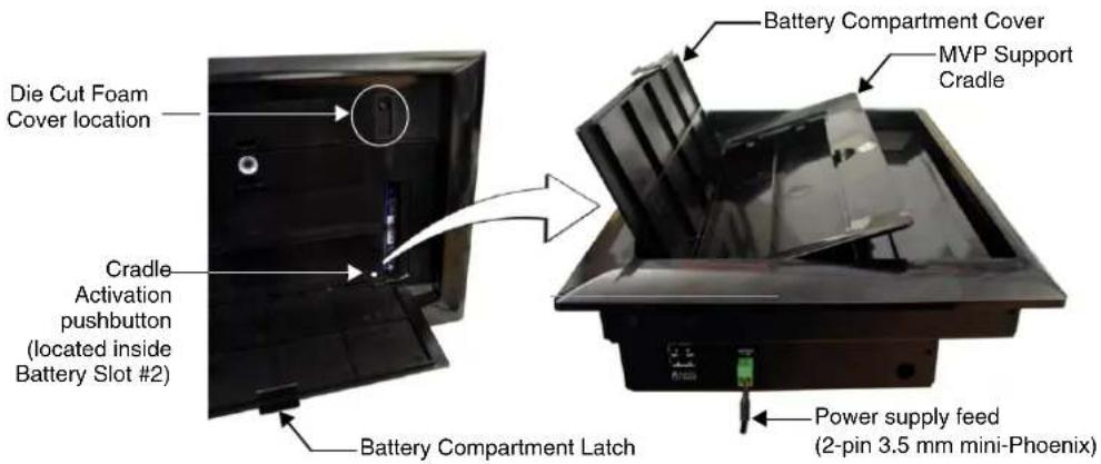
FIG. 19 Cradle activation pushbutton location and cradle angling
-
Disconnect the 2-pin mini-Phoenix connector from the side of the docking station to remove power from the unit and maintain the support cradle in this angled position.
-
Close the battery cover.
-
Remove the two #6-32 Faceplate Security Screws from the top rim of the faceplate (FIG. 20) and place these aside.
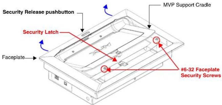
FIG. 20 Faceplate screw removal
-
Position the MVP-WDS unit so the Security Release pushbutton is positioned directly in front of you, then grasp the top rim of the faceplate and begin to angle it upwards. At this point, the faceplate is still connected to the Security Latch (located behind the securing magnet, as shown in FIG. 20).
-
Hold down the unit with both hands and (in one motion), pull the top rim of the faceplate directly towards you and then over the Security Latch to allow it to be removed from the main unit.
-
Grab the bottom rim of the faceplate and place your thumbs just below either side of the Security Release Pushbutton.
-
In one single motion, use your thumbs to push the bottom rim towards the cradle, and then pull it upwards to slide the four faceplate connectors up and away from their respective securing latches along the bottom of the MVP-WDS (FIG. 21).
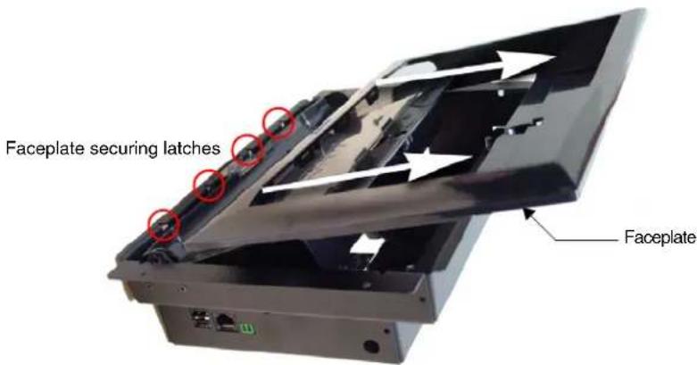
FIG. 21 Faceplate removal from MVP-WDS

NOTE
As you are removing the faceplate, you will have to press down on the Security Latch to allow a complete removal of the faceplate.
- Press downward on the Security Latch (towards the pushbutton) to get it to go through the top opening and allow the faceplate's removal.
- Grab the top rim of the faceplate and carefully slide it over the cradle (at an angle) until the faceplate is completely removed from the MVP-WDS.
Removing the existing black pivot unit (battery and cradle combo)
- Unscrew the two MVP Support Cradle Securing screws, located on the lower right side of the unit (just above the USB connectors) (FIG. 22) and set them aside.
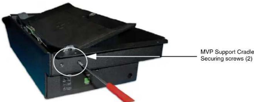
FIG. 22 Removing the MVP Support Cradle securing screws
- Insert the screwdriver into the large hole on the side of the existing black WDS housing (FIG. 22).
- Position the unit to allow a clear view through the gap between the cradle and the rim of the metallic WDS housing (FIG. 23). This view allows you to orient the alignment between the tip of the screwdriver and the screw holding the support cradle to its associated movement mechanism.
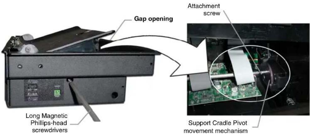
FIG. 23 Separating the support cradle from its movement mechanism
-
Carefully remove the cradle pivot's attachment screw and place it aside for later re-attachment.
-
Carefully slide the black pivot cradle combo unit (battery cover/support cradle) up from the metallic housing and use the screwdriver to remove the remaining screw from the securing plate (shown in FIG. 24).
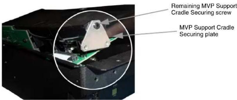
FIG. 24 Sliding out the battery cover/support cradle combo
- Place this securing plate aside (along with its three securing screws).

Use care when removing this black pivot combo as it is still connected to two separate internal circuit boards along its backside. The removal of these circuit boards is the last step before installation of the replacement MVP-WDS/Silver unit.
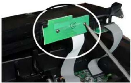
- Locate the exposed MVP Interface Connector pin circuit board and use the screwdriver to remove this board from the combo unit by unscrewing the two screws (A in FIG. 25).
Circuit board A
natural_image
Close-up of a green electronic component being inserted into a battery, with a magnified inset showing the cable assembly (no text or symbols visible)Circuit board B

natural_image
Close-up of a green DVD drive being placed on a black electronic circuit board (no visible text or symbols)FIG. 25 Removing the attached circuit boards (A & B)
- Carefully place the first circuit board aside and rotate the black pivot combo unit over to expose the second circuit board attached to the backside of the unit (B in FIG. 25).
- Carefully remove this second board by unscrewing the three screws and then gently placing this board aside (B in FIG. 25).
- Place the black pivot combo unit aside.
Installing the new conversion kit's pivot unit components
- Gently align the second circuit board (B in FIG. 25) on the underside of the silver cradle pivot unit shown in FIG. 25.

DO NOT OVERTIGHTEN these screws or you will crack the board.
- Use a grounded Phillips-head screwdriver to carefully secure this board to the backside of the unit using the three securing screws.
- Rotate the pivot unit back over to expose the installation location for the MVP Interface Connector pin circuit board (A in FIG. 25) and use a grounded Phillips-head screwdriver to secure this remaining board to the silver pivot unit by screwing in the two securing screws.

If the connector pins do not properly align after installation, you might have to return to this step and unscrew these screws by 1/8th of a turn to allow for some very slight movement.
- Install the silver Battery Cover to the silver cradle pivot by inserting each battery cover guide into its corresponding opening along the sides of the pivot as shown in FIG. 26.
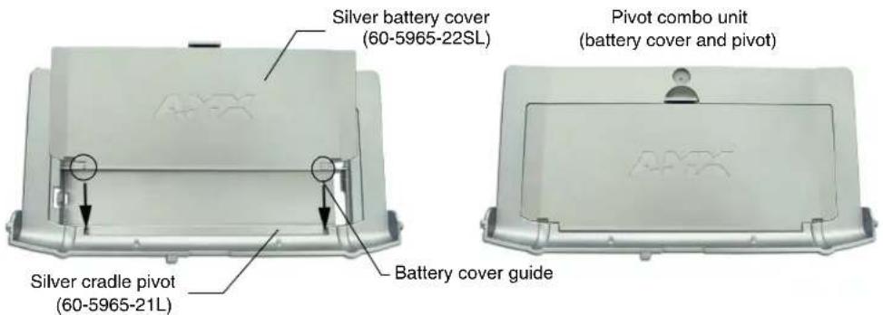
FIG. 26 Installation of silver cradle pivot and battery cover
- Use the screwdriver to install one of the previously removed MVP Support Cradle Securing screws to the securing plate (shown in FIG. 24 on page 22).
- Carefully slide the entire silver battery pivot combo unit into the black WDS metal housing. Be careful not to knock or damage the interface connector pin circuit board.
- Insert the screwdriver (with attached securing screw) into the large hole along the side of the WDS housing (shown in FIG. 23 on page 22).
- Position the unit so you can get a better view and orient the position of this screw back into its location where it secures the support cradle to its associated movement mechanism (shown in FIG. 23 on page 22).
- Carefully secure the cradle pivot's attachment screw. This procedure limits the movement of the silver pivot combo unit.
- Align the MVP Support Cradle Securing plate (FIG. 22 on page 21) to its corresponding holes along the outside of the housing and screw in the remaining two MVP Support Cradle Securing screws back to the lower right side of the unit (FIG. 22 on page 21).
- Place the magnetic cup into the circular Securing Magnet location and secure it to the pivot combo unit by using a grounded flat-head Phillips screwdriver to screw in the single #4-20 Magnet Securing screw (80-0193-01) through the cup.
- Place the small circular rare earth magnet (68-5965-02) into the secured magnetic cup. The charge on the magnet allows it to stay in place and remain flush against the magnetic cup.
Installing the new silver faceplate
- Turn the pre-existing black faceplate over to expose the rear of the illuminated pushbutton.
- In a single motion carefully squeeze both sides of the rear pushbutton and apply downward pressure to pop it out from the black faceplate.
- Take the previously removed illuminated pushbutton and apply downward pressure to insert it into the opening along the bottom of the silver faceplate (until you hear a click).
- Verify that the Security Release Pushbutton is now properly aligned over it's LEDs and circuit board on the MVP-WDS main unit.
- Verify the MVP Support Cradle is angled upwards. This position allows you to slide on the faceplate. If the cradle is not angled upwards:
- Connect the 3.5 mm mini-Phoenix connector from an active power supply to the side PWR connector on the MVP-WDS. The two blue LEDs behind the Security Release pushbutton should illuminate to indicate that the unit is receiving power.
- Open the Battery Compartment by pressing down on the Battery Compartment Latch and then pulling the cover outwards.
- Press the Cradle Activation pushbutton (the small recessed white button located near the pins in Battery Slot #2) to make the MVP Support Cradle rise upwards. The MVP Support Cradle must be angled upward to allow removal of the faceplate.
-
Disconnect the 2-pin mini-Phoenix connector from the side of the docking station to remove power from the unit. Removing power from the MVP-WDS at this point maintains the support cradle in this angled position.
-
Slide the silver Faceplate over the angled Support Cradle, toward the Security Release Pushbutton's circuit board on the MVP-WDS.
-
Gently press the silver faceplate down and under the Security Latch until it rests against the Mounting Tabs of the MVP-WDS main unit.
-
Be sure to snap the Faceplate Connectors into their respective Latches (located along the bottom rim of the faceplate - see FIG. 21 on page 21).
-
Verify that the two faceplate security screw holes on both the Faceplate and the main MVP-WDS unit are properly aligned.
-
Insert and secure the two #6-32 Faceplate Security Screws into the top rim of the Faceplate using a screwdriver.
-
Apply power to the MVP-WDS by connecting the terminal end of the power cable to the power supply.
-
Press the Cradle Activation pushbutton to cause the MVP Support Cradle to angle backwards and lie flush against the main unit.
-
Remove the two adhesive plastic Die Cut Foam covers (60-5965-47) from the strip included within the Installation Kit bag.
-
Adhere these two plastic Die Cut Foam covers into the two notches where the #6-32 Faceplate Security Screws are located (FIG. 19 on page 20).
-
Reapply power to the unit.
- Refer to the Connecting a Power Supply section on page 14 for more information.
- Install the WDS back into its previous location.
- Refer to the Installation section on page 4 for more information.
Upgrading the Docking Station Firmware
The following accessory devices are firmware upgradeable:
● MVP-TDS Table Top Docking Station (FG5965-10)
● MVP-WDS Wall/Flush Mount Docking Station - Black (FG5965-11)
● MVP-WDS Wall/Flush Mount Docking Station - Silver (FG5965-21)
This device is not given a unique device number which would ordinarily appear within the Online Tree tab of NetLinx Studio. It appears as a battery base below the target panel which it is a part of as seen below in FIG. 1.
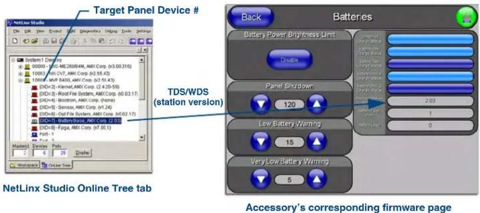
FIG. 1 Location of Firmware version information within NetLinx Studio
The only way to upgrade the firmware of these accessory items is to send the accessory's firmware through a target panel. Its this panel's device number which is entered within the Send to NetLinx Device transfer dialog in Studio.
Step 1: Prepare the Docking Station for firmware transfer via USB
Before beginning with this section:
- Verify the MVP is securely attached to the docking station and communicating properly.
-
Verify that the panel is communicating from the mini-USB port to the Virtual NetLinx Master (VNM).
-
Configure the NetLinx Master for IP communication. Refer to the MVP-7500/8400 Operation/Reference Guide (available online at www.amx.com) for information.
- After the panel powers-up, press and hold the two lower buttons on both sides of the display for 3 seconds to continue with the setup process and proceed to the Setup page.
- Press the Batteries button to open the Batteries page (FIG. 2).
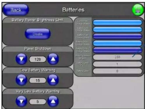
Displays the current docking station firmware version
FIG. 2 Batteries page

The docking station firmware is shown on the right of the Batteries page. Verify you have downloaded the latest firmware file from www.amx.com and then save the Kit file to your computer.
Step 2: Upgrade the Docking Station firmware via USB
- Configure the panel for a USB Connection Type.
- Prepare NetLinx Studio for communication to the panel via a Virtual Master.

Refer to the MVP-7500/8400 Operation/Reference Guide (available online at www.amx.com) for information on configuring communications on the panel.
- After the Communication Verification dialog window verifies active communication between the Virtual Master and the panel, click the OnLine Tree tab in the Workspace window to view the devices on the Virtual System. The default System value is one.
- Right-click on the System entry and select Refresh System to re-populate the list. Verify the panel appears in the OnLine Tree tab of the Workspace window. The default Modero panel value is 10001.
- Locate the latest firmware file from the www.amx.com > Tech Center > Downloadable Files > Firmware Files > Modero Panels firmware (MVP Docking Stations: MVP-TDS/WDS) section of the website.
- Click on the desired Kit file link and after you've accepted the Licensing Agreement, verify you have downloaded the Docking Station Kit file to a known location.
- Select Tools > Firmware Transfers > Send to NetLinx Device from the Main menu to open the Send to NetLinx Device dialog (FIG. 3). Verify the panel's System and Device number values match those values listed within the System folder in the OnLine Tree tab of the Workspace window.
- Select the docking station's Kit file (ending in VXX.kit) from the Files section (FIG. 3).
- Enter the Device number associated with the panel and the System number associated with the Master (listed in the OnLine Tree tab of the Workspace window). The Port field is greyed-out.
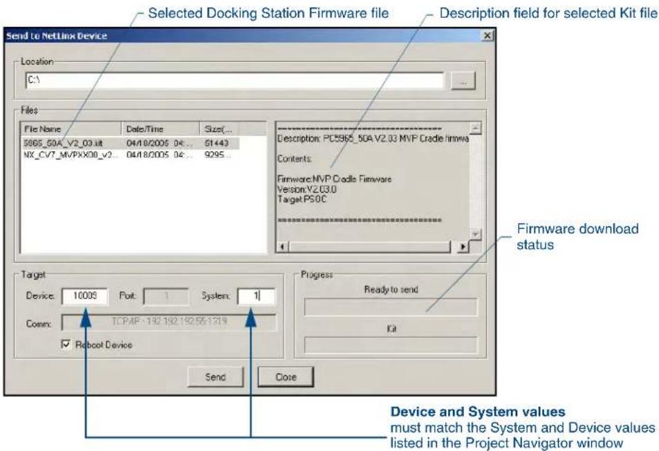
FIG. 3 Send to NetLinx Device dialog (showing docking station firmware update via USB)

Firmware upgrades can not be done directly to the docking station but must be routed through the MVP panel.
- Click the Reboot Device checkbox. This causes the touch panel to reboot after the firmware update process is complete. The reboot of the panel can take up 30 seconds after the firmware process has finished.
- Click Send to begin the transfer. The file transfer progress is indicated on the bottom-right of the dialog.
- As the panel is rebooting, temporarily unplug the USB connector on the panel until the panel has completely restarted.
- Once the first panel page has been displayed, reconnect the USB connector to the panel.
- Right-click the associated System number and select Refresh System. This causes a refresh of all project systems, establishes a new connection to the Master, and populates the System list with devices on your particular system.
- After the panel powers-up, press and hold the two lower buttons on both sides of the display for 3 seconds to continue with the setup process and proceed to the Setup page.
- Press the Batteries button (located on the lower-left) to open the Batteries page and confirm the new firmware does not read 0.00.

If the Base Version field displays 0.00, this means there was an error in the firmware upload process. Re-install the base firmware and re-confirm that the new base version no longer reads 0.00.

Although firmware upgrades can be done over wireless Ethernet; it is recommended that firmware KIT files be transferred over a direct USB connection and only when the panel is connected to a power supply. If battery power or wireless connection fails during a firmware upgrade, the panel flash file system may become corrupted.
Upgrading the Docking Station Firmware
AMX®
It's Your World - Take Control™
93-5965-13 REV E
11 10 11 12 13 14 15 16 17 18
- Wall Docking Station
- AMX Limited Warranty and Disclaimer
- FCC Information
- Federal Communications Commission (FCC) Statement
- FCC RF Radiation Exposure Statement
- Table of Contents
- MVP-WDS Wall Docking Station & CB-MVPWDS Rough-In Box 1
- Upgrading the Docking Station Firmware 27
- MVP-WDS Wall Docking Station & CB-MVPWDS Rough-In Box
- Overview
- MVP-WDS docking station connector locations
- LED Indicators
- Installation
- Installing the CB-MVPWDS Rough-In Box
- Removing the MVP-WDS Faceplate
- Installing the MVP-WDS in a CB-MVPWDS Rough-In Box
- Installing the MVP-WDS Using Expansion Clips
- Installing the MVP-WDS Into a Flat Surface Using Mounting Screws
- Replacing the Faceplate on the MVP-WDS
- Connecting a Power Supply
- Powering the MVP-WDS
- Using the 3.5mm mini-Phoenix Connector for Power
- Connecting and Using USB Input Devices on the Stations
- The MVP does not recognize the keyboard and/or mouse (connected to the docking station) until after the MVP itself has been rebooted.
- Interface Connector Pins and Functions
- Securing an MVP Panel to an MVP-WDS
- Removing an MVP Panel from an MVP-WDS
- Unsecured MVP removal from an MVP-WDS
- Secured MVP removal from an MVP-WDS
- Undock- String
- Installing and Charging Batteries in the Docking Stations
- Installing MVP-BP Batteries Into the MVP-WDS
- Installing the MVP-WDS-SK Silver Conversion Kit
- Removing the original faceplate
- Removing the existing black pivot unit (battery and cradle combo)
- Installing the new conversion kit's pivot unit components
- Installing the new silver faceplate
- Upgrading the Docking Station Firmware
- Step 1: Prepare the Docking Station for firmware transfer via USB
- Step 2: Upgrade the Docking Station firmware via USB
Brand : AMX
Model : MVP-WDS
Category : Computer Accessories