
LNS-T02E - Projector Accessories SANYO - Free user manual and instructions
Find the device manual for free LNS-T02E SANYO in PDF.


| Product Type | Projector Replacement Lens |
| Brand | Sanyo |
| Model | LNS-T02E |
| Compatible Projectors | Select Sanyo models (e.g., PLC series) |
| Focal Length | Approx. 25-30 mm |
| Aperture | f/2.0 - f/2.5 |
| Zoom Ratio | 1.2x manual zoom |
| Lens Shift | Vertical only (approx. ±10%) |
| Weight | Approx. 0.5 kg |
| Dimensions (LxWxH) | Approx. 10 x 8 x 8 cm |
| Material | Glass optics, plastic housing |
| Color | Black |
| Mount Type | Bayonet |
| Included Accessories | Lens cap, user manual |
| Cleaning | Use a soft, dry cloth; avoid solvents |
| Storage | Store in a cool, dry place |
| Repairability | Replacement by authorized service center |
Frequently Asked Questions - LNS-T02E SANYO
User questions about LNS-T02E SANYO
0 question about this device. Answer the ones you know or ask your own.
Ask a new question about this device
Download the instructions for your Projector Accessories in PDF format for free! Find your manual LNS-T02E - SANYO and take your electronic device back in hand. On this page are published all the documents necessary for the use of your device. LNS-T02E by SANYO.
USER MANUAL LNS-T02E SANYO
NOTES ON LENS INSTALLATION
Lens installation should be performed by the qualified service personnel.
It should be followed by this procedure precisely.
Before attempt to install the lens, confirm the model number (both the LCD
projector and the lens) and use the proper lens.
If you have any questions, contact to the dealers.
PARTS LIST
Following parts are contained in the packing.
· LENS 1 piece
· LENS MOUNTING SCREWS 6 screws (2 for spare)
- DRIVER 1 piece
· LIGHT-BLOCK SHEET 1 sheet
- LENS COVER (UPPER · LOWER) 1 set
Following checks and confirmations should be taken for safety.
Check the following things by the time of the cabinet assembly after the lens installation.
- Confirm the lens is securely fixed by 4 screws.
- Wiring must not be tangled in the gear of the lens motor or the other mechanical part.
- There is no missing part, or no loosing mounting part.
LENS REPLACEMENT AND INSTALLATION PROCEDURE
Perform the steps to for lens replacement and installation.
First, set the lens at the center position with lens shift button.
1 REMOVE THE LENS COVER.
First check the shape of cabinet.
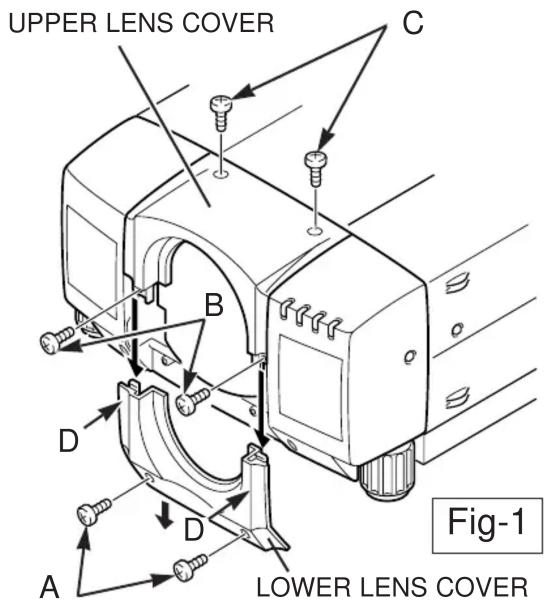
In case figure-1 cabinet.
- Remove screws A (2 screws).
- Pull down the lower lens cover while pushing the part D, then remove it.
- Remove screws B (2 screws).
- Remove screws C (2 screws) and remove upper lens cover.
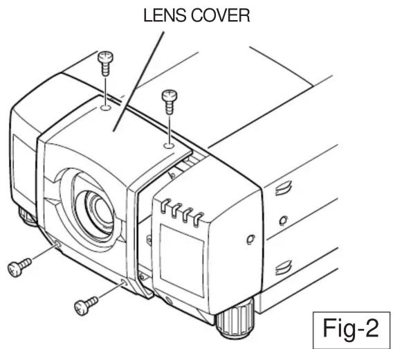
In case figure-2 cabinet.
Remove 4 screws of the lens cover and remove the lens cover.
2
●IN CASE OF MODEL WITHOUT LENS
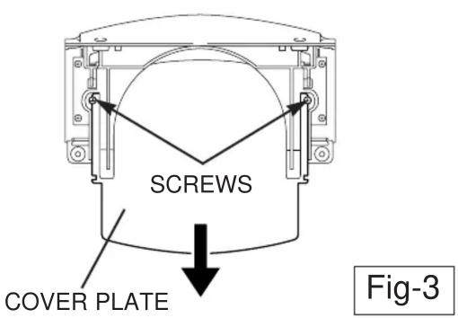
REMOVE THE COVER PLATE OF THE LENS COVER. (See figure-3)
Remove 2 screws and pull down the plate.
(At the step 5 insert the light-block sheet in the same position as the removed cover plate has been placed. Two screws are not used.)
Use the light-block sheet included with lens.

natural_image
Simple black icon of a mechanical component with a circular hole and a curved arrow pointing downward (no text or symbols)Set the light-block sheet, so that the large rounder side is set over the lens.
LIGHT-BLOCK SHEET
●IN CASE OF MODEL WITH LENS
REMOVE THE LENS. (See figure-4)
- Remove the connector "K16B" of the circuit board.
- Loosen the A, B, C wire holder and remove the lens motor lead.
- Remove screws D (4 screws) which fastens the lens and remove the lens.
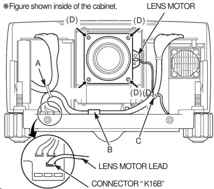
Fig-4
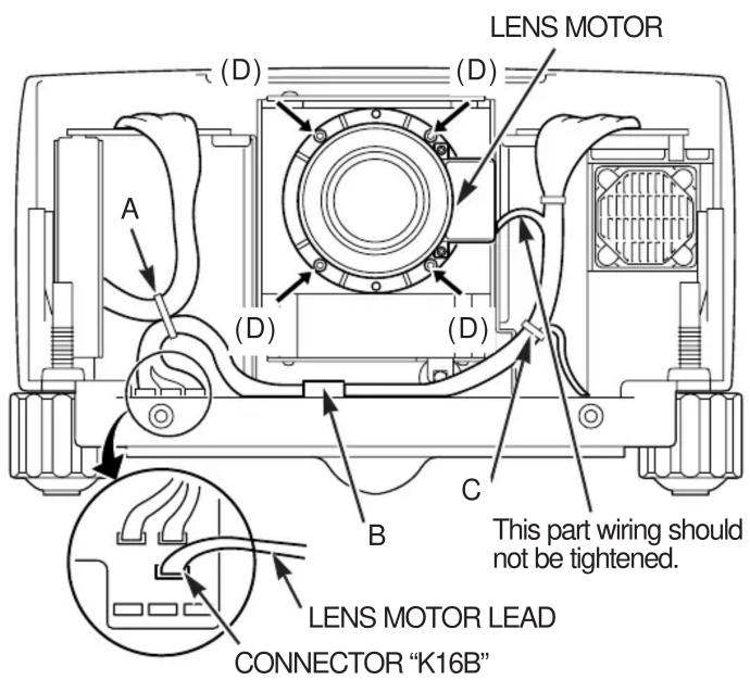
3 INSTALL THE LENS. (See figure-4,5)
- Remove protective caps (front and back) on the lens.
- Mount the lens at the lens mounting bracket with screws (4 screws) included with the lens. Use the driver included with the lens to fasten the screws. (After using, save it for latter use.) (See figure-5)
- Connect the lens motor lead to the connector "K16B" of the circuit board. (See figure-4)
- Fasten the lens motor lead at the A, B, C points with wire holder.
(See figure-4)
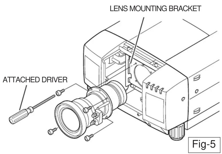
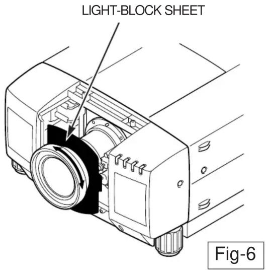
4 INSTALL THE LIGHT-BLOCK SHEET. (See figure-6)
Install the light-block sheet around the lens as shown in the illustration.
(Use the sheet included with the lens.)
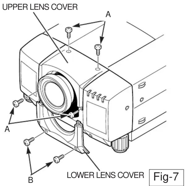
5 MOUNT THE LENS COVER. (See figure-7)
When in install the both upper and lower lens covers, put the light-block sheet through the lens and install the sheet so that it should be placed in the guide slot of the lens cover. (See figure-8) If the installation of the light-block sheet is incorrect, there will be the space between lens and the lens cover, so that it will be the cause of leakage of light or the dust entering at the main cabinet.
- Insert the upper part lens cover and fix them with screws A (4 screws).
- Insert the lower part lens cover and fix them with screws B (2 screws).
*Removed lens cover in figure-2 is not used, keep the cover for possible reuse when current lens is used.
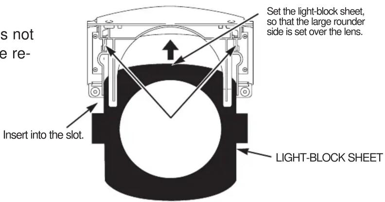
Fig-8
Brand : SANYO
Model : LNS-T02E
Category : Projector Accessories