TA-2700 - Car radio Ultimate - Free user manual and instructions
Find the device manual for free TA-2700 Ultimate in PDF.


| Product Type | Car Audio Amplifier |
| Channels | 2 Channels |
| RMS Power (4Ω) | 2 x 200 Watts |
| Max Power (4Ω) | 2 x 400 Watts |
| RMS Power (2Ω) | 2 x 300 Watts |
| Max Power (2Ω) | 2 x 600 Watts |
| Bridged RMS Power (4Ω) | 1 x 600 Watts |
| Bridged Max Power (4Ω) | 1 x 1200 Watts |
| Minimum Impedance | 2Ω Stereo / 4Ω Bridged |
| Frequency Response | 10 Hz - 30 kHz |
| Signal-to-Noise Ratio | -90 dBA |
| Input Sensitivity | 100 mV - 1.5 V |
| Inputs | RCA Line Level, High Level Speaker Input |
| Crossover | Low Pass (LPF) / High Pass (HPF), 12 dB/Octave, 50-250 Hz |
| Bass Boost | +12 dB @ 45 Hz |
| Protection Circuits | Thermal, Short Circuit, DC Offset, Fuse |
| Fuse Rating | 2 x 30A |
| Power Supply | PWM MOSFET, 12V Negative Ground |
| Recommended Wire Gauge | Power/Ground: #6-#10 AWG; Speaker: #16 AWG or larger |
| Dimensions | Not specified |
| Weight | Not specified |
Frequently Asked Questions - TA-2700 Ultimate
User questions about TA-2700 Ultimate
0 question about this device. Answer the ones you know or ask your own.
Ask a new question about this device
Download the instructions for your Car radio in PDF format for free! Find your manual TA-2700 - Ultimate and take your electronic device back in hand. On this page are published all the documents necessary for the use of your device. TA-2700 by Ultimate.
USER MANUAL TA-2700 Ultimate
138 University Parkway
Pomona, CA 91768
Toll Free: 888-909-9988
Telephone: 909-594-2604
Fax: 909-594-0191
INTRODUCTION
I. Description
This device is a high power, audio amplifier. Use it responsibly. Very loud music can cause permanent hearing loss. This amplifier is intended for installation in vehicles with a 12-Volt, negative ground electrical system. Attempting to connect or operate the amplifier in another type of electrical system may cause damage to the amplifier or the electrical system.
II. About This Manual
WEAR AMPLIFIERS
Be sure that you have read all operating instructions and understand all safety precautions before installing and operating the amplifier. We recommend that you have your TA series amplifier installed by a specialist.
Follow the Instructions-
The instructions are intended to help you safely obtain the best performance from the amplifier. Carefully follow all installation and operating instructions.
Save the Operating Manual-
Keep the manual in a safe place after installing the amplifier. You may have questions later.
Text Conventions used in this Manual-
Bold-
Headings and important information.
Bold, Underlined-
Very important information.
"Bold"-
As labeled on the amplifier, or quoted from elsewhere in this manual.
III. Safety and Operating Precautions-
Caution!
This symbol warns the user of a potential risk or hazard if instructions are not followed.
⇒ This arrow symbol points to a specific instruction for avoiding a potential hazard.
1. Installation
1.1 Installation- Mounting the Amplifier
Step 1- Disconnect the negative (-) battery cable before mounting the amplifier or making any connections. Check the battery and alternator ground (-) connections. Make sure they are properly connected and free of corrosion
Step 2- Choose a mounting location for your amplifier. Find a location on a flat surface away from heat and moisture. Be sure the mounting location and the drilling of pilot holes for mounting will not present a hazard to any wires, control cables, fuel lines, fuel tanks, hydraulic lines, or other vehicle systems or components. Common mounting locations are under the front passenger seat, or in the trunk area. Choose a location with unimpaired air circulation. The amplifier will dissipate heat more efficiently if mounted vertically.
Step 3- Use the supplied screws. Place the amplifier in the mounting location, and mark the positions of the holes with a marker, pen or pencil. Carefully drill the mounting holes in the marked positions.
Caution!
→ Check carefully before drilling any pilot holes.
Step 4- Use the supplied mounting screws to securely fasten the amplifier to the mounting surface.
1.2 Installation- Power Connections
Step 1- Run a power cable from the battery to the amplifier mounting location. Use rubber grommets to protect the cable anywhere it has to go through metal.
TA4600, TA4320, TA2700, TA2300TA4600TAVG20,TA2700VTA2300 and ground cable.
TA2160TA2#6#10 AWG or larger power and ground cable.
Step 2- Connect one end of an in-line fuse holder to the power cable. Connect the other end of the fuse holder to the positive battery post with 20cm (or less) of the same cable. This fuse location will protect the system and the vehicle against the possibility of a short circuit in the power cable. Be sure to use a fuse and fuse holder adequate for the application. Do not place a fuse in the holder at this time.
The maximum fuse rating for each amplifier in the TATA series is:
TA4600 - 2X30 Amp
TA2700 - 2 X 30 Amp
TA4320 - 40 Amp
TA2300 - 30 Amp
TA2160 - 20 Amp
Caution!
Bridging fuses or replacing a fuse with one of a higher rating may cause damage to the amplifier and the vehicle's electrical system.
Step 3- Run a remote turn on cable from the switched +12V source you will be using to turn on the system components. This may be a toggle switch, a relay, or your source unit's remote trigger wire, or power antenna trigger wire. Run this lead to the amplifier mounting location. Use #18 AWG wire or larger.
POWERPOWER +12V RMT GND Step 4 Locate a secure grounding connection as close to the amplifier as possible. Make sure the location is clean and provides a direct electrical connection to the frame of the vehicle. Connect one end of a short piece of the same size cable as
the power cable to the grounding point. Run the other end of the cable to the amplifier mounting location.
Step 5- connect the ground cable to the screw terminal labeled "POWER, GND".
Step 6- Connect the power cable to the amplifier at the screw terminal labeled "POWER, +12V".
Step 7- Connect the remote turn on cable to the screw terminal labeled "POWER, RMT".
1.3 Installation- Speaker Connections
Step 1- Run #16 AWG or larger connecting wire from your speakers to the amplifier mounting location. Keep speaker wires away from power cables and amplifier input cables. Use grommets anywhere the wires have to pass through holes in the metal frame or sheet metal. Connect to the speakers according to the type of terminals on each speaker.
Step 2- Strip 3/8" of insulation from the end of each wire and twist the wire strands together tightly. Make sure there are no stray strands that might touch other wires or terminals and cause a short circuit.
Step 3- Crimp spade lugs over the wire ends or tin the ends with solder to provide a secure termination.
Step 4- Connect the wire ends to your amplifier as follows:
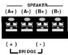
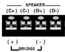
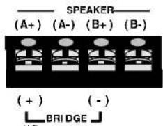
SPEAKER TERMINALS
Follow the (A/B/C/D+) (A/B/C/D-), channel and polarity markings, making sure they match the channel and polarity of the connections at the speakers.
MULTIPLE SPEAKER CONNECTION
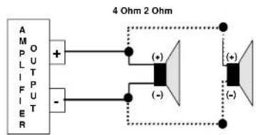
PARALLEL- Each additional speaker decreases the load impedance for the amplifier. The amplifier delivers more current and works harder.
PARALLEL CONNECTION USING 4 OHM SPEAKERS
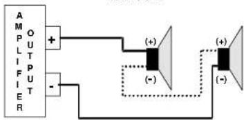
SERIES- Each additional speaker increases the load impedance for the amplifier. Impedances higher than 8 ohms are rarely used for car audio.
SERIES CONNECTION USING 4 OHM SPEAKERS
4 Ohm 8 Ohm
1.4 Installation- Self-Bridging, 2+1 Mode
BRIDGED MONO-
Connect a 4Ω ohm speaker to the terminals marked “(+), BRIDGE, (-)”, making sure they match the polarity of the connections at the speakers.
Caution!
⇒ Speaker or multiple speaker loads totaling less than 4 ohms are not recommended for “Bridged” or “2+1 Mode”, and may damage th
TA4600, TA4320TA4600, TA4320-- Set the "MODE" switch to "2CH, 3CH", or "4CH" and connect the speakers accordingly. For "3CH" operation, bridge the "C" and "D" channels.
2+1 MODE- (TRI-MODE)
Simultaneous stereo and mono operation, "2+1 Mode", requires a passive crossover to send low frequencies to the mono speaker and higher frequencies to the stereo speakers. The following table lists the component values for a 6 dB/Octave crossover at common frequencies using 4 ohm speakers for stereo and an 8Ω speaker for mono(subwoofer):
| FREQUENCY | INDUCTOR | CAPACITOR | |
| 80 Hz | 16 mH | 470 uF | |
| 100 Hz | 7.5 mH | 330 uF | |
| 120 Hz | 7.5mH | 330 uF | |
| 150 Hz | 7.5 mH | 220 uF | |
2+1 MODE WIRING DIAGRAM-
Use 100 Volt, non-polar capacitors, and connect them in series with the stereo speakers as shown in the diagram. Connect the inductor in series with the mono speaker as shown in the diagram. Be sure the inductor is rated to handle the power of your amplifier.

flowchart
graph TD
    A["(A+)"] --> C["Capacitors Inductor"]
    B["(A-)"] --> C
    D["(B+)"] --> E["Capacitors Inductor"]
    F["(B-)"] --> E
    C --> G["Output"]
    E --> H["Output"]
1.5 Installation- Input Connections
Low Level, High Impedance, Gold Plated RCA Input Jacks-
For connecting to a source providing preamp level outputs. Use heavy duty RCA patch cords designed for mobile applications. Run the patch cables carefully, maintaining as much distance as possible from power, speaker, and accessory wiring. Make sure the RCA plugs fit tightly for a secure connection.
INPUTI


Speaker Level Input Connector-
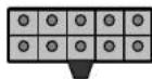
HIGH LEVEL Use the supplied wiring harness to connect the speaker outputs from the source unit(AM/FM/CD/DVD or Cassette) to the "HIGH LEVEL" input.

| Wiring Harness Color Code- 2 Channel | |
| White Wire | A Channel Positive( + ) |
| White/Black Wire | A Channel Negative( - ) |
| Gray Wire | B Channel Positive( + ) |
| Gray/Black Wire | B Channel Negative( - ) |
| Black Wire Ground | |
| No Other Connection | |
HIGH LEVELH
| Wiring Harness Color Code- 4 Channel | |
| White Wire Channel A | Positive( + ) |
| White/Black Wire | Channel A Negative( - ) |
| Gray Wire Channel B | Positive( + ) |
| Gray/Black Wire | Channel B Negative( - ) |
| Green Wire Channel C | Positive( + ) |
| Green/Black Wire | Channel C Negative( - ) |
| Violet Wire Channel D | Positive( + ) |
| Violet/Black Wire | Channel D Negative( - ) |
| Black Wire Ground | |
| No Other Connection | |
1.6 Installation- Check all Connections
Recheck all connections before reconnecting the negative(-) battery cable. Insert the correct value fuse in the fuse holder at the battery before attempting to turn on the system.
2. Operation
2.1 Operation- Input Level adjustments
Adjust the input level for the marked channel(s) with a small screwdriver through the opening marked "LEVEL". Turn CW(clockwise) to increase the level, CCW(counterclockwise) to decrease. Amplifiers will run cooler and produce less system noise at lower level settings.
Consult an experienced installation specialist for assistance in balancing the levels in multi-amplifier systems, or systems with signal processing accessories.
2.2 Operation- Built-in Crossovers
CROSSOVER FILTER SELECTION
X-OVERX-

LPF- FULL- HPFLP-FDLL-HPF the position of the slide switch for each pair of channels. "LPF" selects the low pass filter. "HPF"
selects the high pass filter. Selecting "FULL" defeats the crossover functions
FREQUENCY ADJUSTMENT
LPFLPF

40-2404
After selecting the crossover function, adjust the low pass or high pass frequency control with a small screwdriver through the opening marked "LP/FREQ." or "IP/FREQ.". Turn CW to set to a higher frequency, CCW to set to a lower frequency.
BASS-BOOSTBASS-BOOST

Turning the "BASS BOOST" switch to "ON" increases the level of frequencies around 45Hz by 12dB.
2.3 Operation- Protection Circuits and
L.E.D. Indicators

"POWER." L.E.D. INDICATOR- Provides a visual indication that the amplifier is turned on.
POWERPOWER

"PROTECT" L.E.D. INDICATOR- Provides a visual
indication that a problem exists and the protection circuitry has PROTECTPROTECTED the amplifier by shutting it down. Turn the system off and correct the problem before turning the system on.
THERMAL PROTECTION- The amplifier will shut down if its temperature exceeds a safe operating level. The amplifier will remain off until it cools to a safe operating temperature. Exercise care, the exterior of the amplifier may get uncomfortably hot to the touch before shutting down.
OVERLOAD AND SHORT CIRCUIT PROTECTION- The amplifier will shut down if a short circuit condition exists, or if electrical current demands exceed safe levels.
FUSEFUSE PROTECTION- A blown fuse indicates a problem that 15A15A should be corrected before the fuse is replaced. Always replace with the same value fuse. Never substitute a larger value fuse.

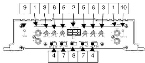
2.4 Operation- Location of Terminals, Controls and LED indicators
TA4600, TA4320TA4600, TA4320
- RCA input jacks 2. High level input 3. Input level adjust
- Crossover select 5. Low pass freq. 6. High pass freq.
- Bass boost 8. Mode 9. Power L.E.D.
- Protection L.E.D.
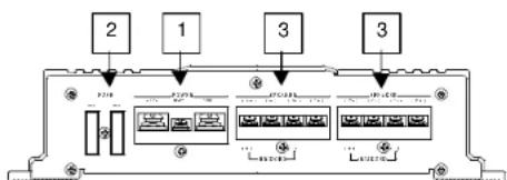
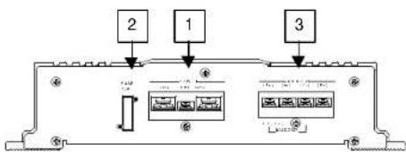
- Power terminals 2. Fuse(s) 3. Speaker terminals
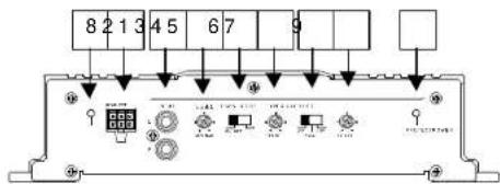
TA2700, TA2300, TA2160TA2700, TA2300, TA2160
- RCA input jacks 2. High level input 3. Input level adjust
- Bass Boost 5. Low pass freq. 6. Crossover select
- High pass freq. 8. Power L.E.D. 9. Protection L.E.D.
- Power terminals 2. Fuse(s) 3. Speaker terminals
flowchart
graph TD
    A["1"] --> B["2"]
    C["3"] --> D["4"]
    B --> E["Module 1"]
    D --> F["Module 2"]
    style A fill:#f9f,stroke:#333
    style C fill:#f9f,stroke:#333
    style B fill:#ccf,stroke:#333
    style D fill:#ccf,stroke:#333
Features and Specifications:
| TA46004 CHANNEL POWER AMPLIFIER | TA43204 CHANNEL POWER AMPLIFIER | TA27002 CHANNEL POWER AMPLIFIER | TA23002 CHANNEL POWER AMPLIFIER | TA21602 CHANNEL POWER AMPLIFIER | |
| 2Ω Stable | Yes | ||||
| Bridgeable | Yes, 4Ω | ||||
| Tri-mode | Yes | ||||
| Terminals | Gold plated RCA jacks, speaker and power terminals | ||||
| Soft Start | Yes | ||||
| Inputs | RCA line level inputs, High level inputs | ||||
| Crossover | Low Pass, High Pass, 12dB/Octave, 50-250Hz. | ||||
| Bass Boost | +12dB @ 45Hz | ||||
| Protection | Thermal, short-circuit, DC offset, fuse | ||||
| Power Supply | Pulse Width Modulated, MOSFET power supply, +12V/Negative Ground | ||||
| RMS/Max Power, 4Ω, THD<0.05% | 4 X85/170Watts | 4 X50/100Watts | 2 X200/400Watts | 2 X85/170Watts | 2 X50/100Watts |
| RMS/Max Power, 2Ω, THD<0.2% | 4 X125/250Watts | 4 X70/140Watts | 2 X300/600Watts | 2 X125/250Watts | 2 X80/165Watts |
| Bridged RMS/Max Power, 4Ω | 2 X250/500Watts | 2 X140/280Watts | 600/1200Watts | 250/500Watts | 165/330Watts |
| Signal to Noise Ratio | -90dBA | -90dBA | -90dBA | -90dBA | -90dBA |
| Frequency Response | 10Hz. -30kHz | 10Hz. -30kHz | 10Hz. -30kHz | 10Hz. -30kHz | 10Hz. -30kHz |
| Separation | -60dB | -60dB | -60dB | -60dB | -60dB |
| Input Sensitivity | 100mV -1.5V | 100mV -1.5V | 100mV -1.5V | 100mV -1.5V | 100mV -1.5V |
| Fuse | 2 X 30A | 30A | 2 X 30A | 30A | 15A |
These specifications are subject to change in the continuing effort to improve the product.
Troubleshooting:
| Condition | Possible Cause | Possible Solution |
| No sound Low or no remote turn on voltage, or no remote turn on connectionBlown fuse(s) Check all system fusesWiring problems Recheck all connectionsBlown speakers Check speakers on another amplifier | Check the remote turn on connection and the voltage at the amplifier and source unit | |
| Check for short circuits | ||
| Amplifier shut down | ||
| Distortion | Input level not properly adjustedSpeaker damage | Readjust amplifier input levelCheck speakers on another amplifier |
| Poor bass response | Speakers out of phase | Recheck speaker wiringReverse polarity of one channel |
| Ticking noise | Radiated noise from spark plug wires | Reroute amplifier input wiringInstall a noise filter |
| Whining noise | Alternator noise caused by poor grounding of amplifier, source, other component, battery, or alternator | Check all ground connectionsInstall a noise filter on the source unit's power cableInstall a coupling transformer in the signal path to improve ground isolation for the signal path |
- INTRODUCTION
- Description
- About This Manual
- WEAR AMPLIFIERS
- Safety and Operating Precautions-
- Caution!
- Installation
- Installation- Mounting the Amplifier
- Installation- Power Connections
- Installation- Speaker Connections
- SPEAKER TERMINALS
- MULTIPLE SPEAKER CONNECTION
- Installation- Self-Bridging, 2+1 Mode
- BRIDGED MONO-
- 2+1 MODE- (TRI-MODE)
- 2+1 MODE WIRING DIAGRAM-
- Installation- Input Connections
- Low Level, High Impedance, Gold Plated RCA Input Jacks-
- Speaker Level Input Connector-
- Installation- Check all Connections
- Operation
- Operation- Input Level adjustments
- Operation- Built-in Crossovers
- CROSSOVER FILTER SELECTION
- FREQUENCY ADJUSTMENT
- Operation- Protection Circuits and
- L.E.D. Indicators
- Operation- Location of Terminals, Controls and LED indicators
- TA2700, TA2300, TA2160TA2700, TA2300, TA2160
Brand : Ultimate
Model : TA-2700
Category : Car radio