
CD5201DTST - Clock JUNG - Free user manual and instructions
Find the device manual for free CD5201DTST JUNG in PDF.


| Product Type | Analog/Digital Timer Switch (Clock) |
| Model | CD5201DTST |
| Brand | JUNG |
| Power Supply | Mains voltage via timer insert (e.g., Art.-No. 201 TE) |
| Power Reserve | Approx. 4 hours (storage capacitor) |
| Number of Switching Times | 8 (4 per weekly section: Mo-Fr and Sa+Su) |
| Accuracy | ±1 minute per month |
| Ambient Temperature | 0°C to +45°C |
| Storage/Transport Temperature | -10°C to +60°C |
| Display Type | LCD with segments showing time, day, switching status, and programming |
| Functions | Manual switching, automatic function, programming of up to 8 switching times, automatic summer/winter time changeover, quick programming |
| Intended Use | Manual and time-controlled switching of loads |
| Reset Function | Restores factory defaults (press Prog and Man for >20 s) |
| Maintenance | No regular maintenance required; keep dry and clean |
| Safety | Installation only by electrically skilled persons; disconnect power before mounting |
| Spare Parts / Accessories | Timer switch insert Art.-No. 201 TE |
| Warranty | As provided by law; send defects postage-free to Service Center |
| Dimensions | Standard 55 mm frame compatible |
| Weight | Approx. 50 g (estimated) |
Frequently Asked Questions - CD5201DTST JUNG
User questions about CD5201DTST JUNG
0 question about this device. Answer the ones you know or ask your own.
Ask a new question about this device
Download the instructions for your Clock in PDF format for free! Find your manual CD5201DTST - JUNG and take your electronic device back in hand. On this page are published all the documents necessary for the use of your device. CD5201DTST by JUNG.
USER MANUAL CD5201DTST JUNG
Standard timer switch display
Art.-No.: ..5201 DTST..
Operationsmanual
1 Safety instructions
Electrical equipment may only be installed and fitted by electrically skilled persons.
Failure to observe the instructions may cause damage to the device and result in fire and other hazards.
These instructions are an integral part of the product, and must remain with the end customer.
2 Device components
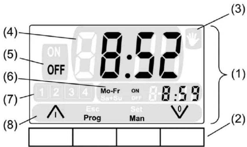
picture 1: Timer with all segments
(1) Display
(2) Buttons
(3) ↓ in display = automatic function OFF
(4) Display field for current time of day
(5) Display field for the status of the switching output
(6) Display field for next switching time for automatic function, or notice text when setting the time of day.
(7) Memory slot of the switching time, only visible during programming
(8) Function display for the buttons
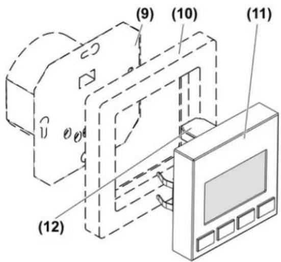
picture 2: Timer device components
(9) Timer insert
(10) Frame
(11) Timer
(12) Plug contact with insert
3 Function
Intended use
- Manual and time-controlled switching of loads
- Operation with timer insert
- Mounting on timer insert
Product characteristics
- Programming of two switch-on times and two switch-off times each for the parts of the week Mo-Fr and Sa+Su
- Programmed switching times are retained permanently
- Display switches off after a power failure, data and time are retained for a power reserve of approx. 4 hours
- Automatic summer/winter time changeover
Behaviour after a mains voltage failure
Loads remain switched off when mains voltage returns.
4 Operation
Set date and time
- Press Prog and Man buttons simultaneously for longer than 10 seconds. Not necessary after reset or power failure.
Time, hour flashes, display field (6) shows HOUR.
■ Set hour with ∧ or ∨ button.
■ Press Set button.
Minute flashes, display field (6) shows MIN.
■ Set minute with ∧ or ∨ button
■ Press Set button.
Year flashes, display field (6) shows YEAR.
■ Set year with ∧ or ∨ button.
■ Press Set button.
■ Set data for month MON and day DAY in the same manner.
Time and date have been saved.
Switching on loads
■ Press ∧ button.
Switching off loads
■ Press ∨ button.
i Loads can be switched on and off manually even when the automatic function is active.
Programming switching times
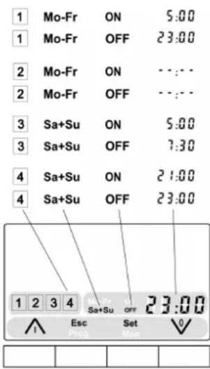
picture 3: Example of program memory
Each memory slot can be programmed with one switch-on time and one switch-off time. Memory slots [1] and [2] are configured for switching times from Monday to Friday, and memory slots [3] and [4] for switching times on Saturday and Sunday (picture 3).
■ Press the Prog button and for longer than 4 seconds.
The switch-on time of the first memory slot Mo-Fr is displayed.
■ Select switching time to be changed using the ∧ or ∨ button. Note the ON/OFF and Mo-Fr/Sa+Su symbols on the display (picture 3).
■ Confirm selection with Set.
The hours display of the switching time flashes.
■ Change hour with ∧ or ∨ button.
■ Press Set button.
The minutes display flashes.
■ Set minutes with ∧ or ∨ button.
■ Press Set button.
Display field (6) shows the next switching time.
■ Program all of the desired switching time in the same manner.
■ Exit programming mode with Esc button.
If more than 2 minutes pass without any operator input, the programming mode is automatically terminated.
Deleting the switching times
■ Press the Prog button and for longer than 4 seconds.
The switch-on time of the first memory slot Mo-Fr is displayed.
■ Select switching time to be deleted using the ∧ or ∨ button.
■ Confirm selection with Set.
The hours display of the switching time flashes.
■ Press ∧ and ∨ buttons simultaneously for longer than 4 seconds.
The switching time displays --:--.
i Alternatively, set time to --:--.
■ Press Set button.
The switching time is deleted.
Deleting all switching times
■ Press the Prog button and for longer than 4 seconds.
The switch-on time of the first memory slot Mo-Fr is displayed.
■ Press Set button.
The hours display of the switching time flashes.
- Press ∧ and ∨ buttons simultaneously for longer than 10 seconds.
The indication goes out.
All switching times have been deleted.
Reset
The state as delivered is restored using the reset function.
■ Press the buttons Prog and Man for longer than 20 seconds.
All switching times have been deleted. Time and date must be set again.
Saving current time as switching time, quick programming
The switching times can also be saved without calling up the programming menu. If desired, the current time of day can be saved as the switching time for the entire week.
Quick programming overwrites the switch-on or switch-off times of memory slots [1] and [3] and deletes the switching times of memory slots [2] and [4] (picture 3).
- Press the ∧ button and at the same time the Prog button for about 4 seconds in order to save the current time as the switch-on time, or
- Press the ∨ button and at the same time the Prog button for about 4 seconds in order to save the current time as the switch-off time.
Time has been set as switch-on or switch-off time and is displayed for approx. 5 seconds.
Switching on automatic function
Switching times have been saved. is shown on display.
- Press Prog button briefly. Next switching time appears in display field (6). Indication ⚪ goes out. Automatic function is activated.
i If no switching time is stored, --:-- appears briefly on the display.
Switching off automatic function
Next switching time is visible in display field (6).
■ Press Man button briefly.
↓ is shown on display.
Deactivating automatic summer/winter time changeover
In the state as delivered, automatic summer/winter time changeover is activated. The timer moves the time forwards one hour to summer time on the last Sunday in March, and back to winter time on the last Sunday in October.
■ Press the button ∧ and Man for longer than 20 seconds.
AU:_1 in display field (4) indicates that automatic changeover is activated.
■ Press ∨ button.
AU:_0 is shown in display field (4). Automatic changeover is deactivated.
■ Press Set button.
Activating automatic summer/winter time changeover
■ Press the button ∧ and Man for longer than 20 seconds.
AU:_0 in display field (4) indicates that automatic changeover is deactivated.
■ Press ∧ button.
AU:_1 is shown in display field (4). Automatic changeover is activated.
■ Press Set button.
5 Information for electrically skilled persons
5.1 Fitting and electrical connection
Fit the timer

DANGER!
Electrical shock when live parts are touched.
Electrical shocks can be fatal.
Disconnect the insert before mounting the timer.
The timer insert is connected (see instructions for insert).
■ Fit timer (11) with frame (10) onto the timer insert (9) (picture 2).
5.2 Commissioning
Making basic settings
The timer is fitted on the insert.
■ Switch on mains voltage.
■ Set date and time (operation).
i In the state as delivered, no switching times are programmed.
■ Program switching time (Operation).
The device is ready for operation.
6 Appendix
6.1 Technical data
Ambient temperature 0 ... +45 °C
Storage/transport temperature -10 ... +60 °C
Number of switching times 8
Accuracy per month ± 1 min
Power reserve from storage capacitor approx. 4 h
6.2 Accessories
Timer switch insert Art.-No.: 201 TE
6.3 Warranty
We reserve the right to make technical and formal changes to the product in the interest of technical progress.
We provide a warranty as provided for by law.
Please send the unit postage-free with a description of the defect to our central customer service office:
ALBRECHT JUNG GMBH & CO. KG
Service Center
Kupferstr. 17-19
D-44532 Lünen
Service-Line: +49 (0) 23 55 . 80 65 51
Telefax: +49 (0) 23 55 . 80 61 89
mail.vka@jung.de
General equipment
Service-Line: +49 (0) 23 55 . 80 65 55
Telefax: +49 (0) 23 55 . 80 62 55
mail.vkm@jung.de
KNX equipment
Service-Line: +49 (0) 23 55 . 80 65 56
Telefax: +49 (0) 23 55 . 80 62 55
mail.vkm@jung.de
The € symbol is a free trade symbol, which is solely intended for the authorities and does not guarantee any properties.
ALBRECHT JUNG GMBH & CO. KG
Vollmestraße 1
- Operationsmanual
- Safety instructions
- Device components
- Function
- Intended use
- Product characteristics
- Behaviour after a mains voltage failure
- Operation
- Set date and time
- Switching on loads
- Switching off loads
- Programming switching times
- Deleting the switching times
- Deleting all switching times
- Reset
- Saving current time as switching time, quick programming
- Switching on automatic function
- Switching off automatic function
- Deactivating automatic summer/winter time changeover
- Activating automatic summer/winter time changeover
- Information for electrically skilled persons
- Fitting and electrical connection
- Fit the timer
- DANGER!
- Commissioning
- Making basic settings
- Appendix
- Technical data
- Accessories
- Warranty
- ALBRECHT JUNG GMBH & CO. KG
- General equipment
- KNX equipment
Brand : JUNG
Model : CD5201DTST
Category : Clock