
GE - Coffee maker GAGGIA - Free user manual and instructions
Find the device manual for free GE GAGGIA in PDF.


| Product Type | Professional espresso coffee machine |
| Brand | Gaggia |
| Model | GE |
| Number of Groups | 2, 3, or 4 groups |
| Dimensions (W x H x D) - 2 groups | 760 x 500 x 540 mm |
| Weight - 2 groups | 70 kg |
| Boiler Capacity - 2 groups | 13 L |
| Electrical Supply | 240/415 V 3 N~, 50/60 Hz (standard); also 230/400 V 3 N~ and 120 V~ |
| Total Absorbed Power - 2 groups (full power) | 5200 W (230-240/400-415 V) |
| Pump Motor Power | 165 W |
| Gas Heating (optional) - 2 groups | 1700 kcal/h |
| Operating Pressure (boiler) | 1.1–1.3 atm |
| Pump Pressure | 8–9 atm |
| Functions | Espresso, long coffee, cappuccino, milk, hot water/tea, continuous dispensing, pre-infusion, mixed tea |
| Programming | Volumetric coffee measures, timed tea delivery, cappuccino and milk delivery |
| Display (optional) | 16x2 LCD, language selection, consumption reading |
| Alarms | Low water level, volumetric counter timeout, washing alarm for milk system |
| Water Connection | Mains water supply (min 8°F hardness), recommended water softener, pressure reducer if >5 bar |
| Gas Connection (optional) | Rubber hose or stainless steel connection, injectors for G20, G30, G110 |
| Maintenance | Daily cleaning of spouts and filters; weekly backflushing with cleaning powder; descaling as needed; seal replacement |
| Safety Features | Earth connection, auto-fill boiler, pressure switch, thermal fuse (on resistance saver) |
| Spare Parts | Filters (single, double, pod), gigleurs (0.6/0.8 mm), spouts, seals, thermostats, pressure switch |
| Documentation | User manual (68 pages) available in multiple languages, PDF download |
Frequently Asked Questions - GE GAGGIA
User questions about GE GAGGIA
0 question about this device. Answer the ones you know or ask your own.
Ask a new question about this device
Download the instructions for your Coffee maker in PDF format for free! Find your manual GE - GAGGIA and take your electronic device back in hand. On this page are published all the documents necessary for the use of your device. GE by GAGGIA.
USER MANUAL GE GAGGIA
natural_image
Line drawing of a coffee machine with multiple gauges and control knobs (no text or symbols)GAGGIA®
ISTRUZIONI PER L'USO
OPERATING INSTRUCTIONS
GEBRAUCHSANWEISUNG
MODE D'EMPLOI
INSTRUCCIONES DE USO
DICHIARAZIONE DI CONFORMITA' CE – DECLARATION DE CONFORMITE CE EG-KONFORMITÄTSERKLÄRUNG – EC DECLARATION OF CONFORMITY DECLARACIÓ DE CONFORMIDAD CE
La Ditta Gaggia s.p.a.
98/37/CE;73/23/CE, 93/68/CE;89/336/CE, 93/68/CE, 92/31/CE;97/23/CE
We thank you for your custom in the purchase of this product.
By carefully following the instructions contained in this manual you will be sure to appreciate the quality of our machine.
Please therefore carefully read the instructions of use contained in this manual, which comply with essential safety regulations.

Carefully read the following instruction booklet before starting up the machine.
Carefully read the following instruction booklet before starting up the machine.
Important! Hot surfaces.
Important! Particularly important and/or delicate operations
Important! Operations essential to guarantee efficient function
Operations which may be carried out by the user
Interventions to be carried out exclusively by an installer or authorized technician.
Fig.6.01
natural_image
Technical illustration of a mechanical assembly with threaded pipe and base component (no text or symbols)Fig.6.02

6.2 REGOLAZIONE DEL PRESSOSTATO
Fig.6.03

6.3 TARATURA PRESSIONE POMPA
natural_image
Technical line drawing of a mechanical valve assembly (no text or symbols)
Attenzione!
NF08/009/B
natural_image
Four identical black-and-white illustrations of coffee cups arranged vertically (no text or symbols)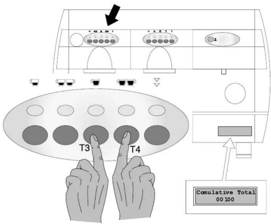
Fig. 8.02
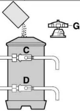
Fig. 8.03
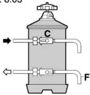
Fig. 8.04
A ENTRATA ACQUA
B USCITA ACQUA
C LEVETTA RUBINETTO ENTRATA
D LEVETTA RUBINETTO USCITA
E TUBETTO DEPRESSIONATORE
F TUBO RIGENERAZIONE
G POMOLO COPERCHIO

Fig.10.01

1 INSTRUCTIONS BOOKLET CONSERVATION AND USE 32
2 ENVISAGED MACHINE USE 32
3 SAFETY ADVICE 33
4 TECHNICAL FEATURES 34
5 INSTALLATION 35
5.1 WATER CONNECTION 35
5.2 ELECTRICAL CONNECTION 35
5.3 GAS CONNECTION 35
6 START UP 36
6.1 LONG COFFEE GIGLEUR 37
6.2 PRESSURE SWITCH ADJUSTMENT .... 37
6.3 PUMP PRESSURE CALIBRATION...... 37
6.4 FILTERS FOR COFFEE MACHINE ..... 37
6.5 REPLACEMENT OF THE THERMOSTAT TO REDUCE THE COFFEE DISPENSING GROUP TEMPERATURE 38
6.6 WITH SPOUTS 38
7 FUNCTION / USE AND PROGRAMMING ... 39
7.1 COFFEE MEASURE PROGRAMMING .... 39
7.2 TEA MEASURE PROGRAMMING (HOT WATER) 41
7.3 COFFEE DELIVERY 42
7.4 CONTINUOUS COFFEE MEASURES . 42
7.5 SPECIAL FUNCTIONS 43
7.6 TEA DELIVERY 44
7.7 CAPPUCCINO AND MILK FUNCTION 45
7.8 CAPPUCCINO DELIVERY AND PROGRAMMING 46
7.9 MILK PROGRAMMING AND DELIVERY 46
7.10 FURTHER FUNCTIONS ON MACHINES EQUIPPED WITH DISPLAY.... 47
7.11 ALARM CONDITION....50
8 PURIFIER REGENERATION 51
9 GAS ADJUSTMENT 52
10 MAINTENANCE AND USEFUL ADVICE ..... 53
11 TROUBLE SHOOTING 54
12 MACHINE DISMANTLING 54
1 - INSTRUCTIONS BOOKLET CONSERVATION AND USE
The present instructions booklet has been prepared for the machine user, the owner and the installation technician and must be always available for reference purposes.
The manual is destined for the user, the maintenance technician and machine installation technician.
The purpose of the instructions booklet is to indicate the envisaged uses of the machine for which it has been designed, its technical features and in order to provide advice on correct use, cleaning and regulation. It also provides important maintenance information, and details on any residual risks, and all those operations which require particular care.
The present manual is to be considered as an integral part of the machine and must be CONSERVED FOR FUTURE REFERENCE until the final dismantling of the machine.
This instructions booklet must always be available for consultation and must be kept in a protected and dry place.
In the event of loss or damage to the same, the user may ask the manufacturer or local dealer for a new manual, indicating the machine model and serial number of the same as indicated on the identification plate.
The present manual reflects the state of the art, at the time of its preparation, the manufacturer however reserves the right to revise production and subsequent manuals without being obliged to update previous versions.
The manufacturer declines all responsibility in the event of :
- the improper or incorrect use of the coffee machine
- use that fails to comply with that specifically stated in the present booklet
- serious lack of maintenance as envisaged or recommended
- machine modifications or any non-authorized intervention
- use of either non-original or non-specific spares
- total or partial failure to observe the instructions
2 - ENVISAGED MACHINE USE
The machine must be operated by a single operator only.
The authorized operator must have firstly read and fully understood all the instructions contained in the present booklet to ensure correct machine function.
This machine is specifically intended for the professional preparation of espresso coffee using blended coffee, as well as the drawing and delivery of water and/or steam.
Its components are made of resilient non toxic materials, and they are easily accessible for cleaning or maintenance operations.
This machine is intended for internal use only.
Ambient temperature for the correct operation of the machine 5^ ÷ 40^ .

3 - SAFETY ADVICE
The machine is to be used solely by adults who have carefully read and fully understood this manual and all the safety advice contained in the same.
The user is responsible in relation to third parties in the working area.
The installer, user and maintenance technician are obliged to notify the constructor of any defects or faults which may effect the original safety of the system.
Installation must be effected solely by authorized and qualified personnel.
The machine is to be used solely in the presence of suitable lighting.
For safety reasons, all worn or damaged parts must be promptly replaced.
Regularly check that the power supply cable is in good conditions. Damaged cables must never be repaired using insulating tape or clamps.
Do not expose the machine to the elements (sun, rain, etc).
Prolonged machine standstill at temperatures of under 0^ C (zero degrees centigrade), may cause serious damage or breakage to the boiler piping: it is therefore necessary to completely empty the water circuit before every prolonged standstill.
The removal of guard and/or safety elements fitted on the machine is forbidden.
The packaging components must be consigned to special disposal centres and must in any event never be left unguarded or within reach of children, animals or non-authorized persons.
The constructor declines responsibility for any damage to things, persons or animals caused by eventual interventions on the machine by personnel not specifically authorized to undertake such operations.
In the event of any non-authorized interventions or repairs on the machine, or in the event of the use of non-original spares all guarantee terms become void, and the company reserves the right to reject validity.
The user must comply with the current safety laws in force in the country of installation, as well as common sense and ensure that all maintenance operations are regularly carried out.
Never clean the inside of the machine with power supply on and plug connected and in any event avoid the use of water sprays or detergents.
The user must not touch the machine if his hands or feet are wet or damp, neither must be use the machine in bare feet. Although the machine is earthed it is advisable to use wooden platforms or a cut-out box complying with local laws in order to prevent the risk of electrocution.
Do not touch the coffee spouts and the hot water and steam nozzles with your hands or any other parts of the body as the liquids or steam issuing from them are very hot and may cause burns.
Avoid operating the machine without water.
Clogging may cause the generation of sudden liquid or steam jets with serious consequences. Therefore keep the water as clean as possible using filters and water softeners.
The cups and small coffee cups must be thoroughly dried before placed on the relative surface.
4 - TECHNICAL FEATURES
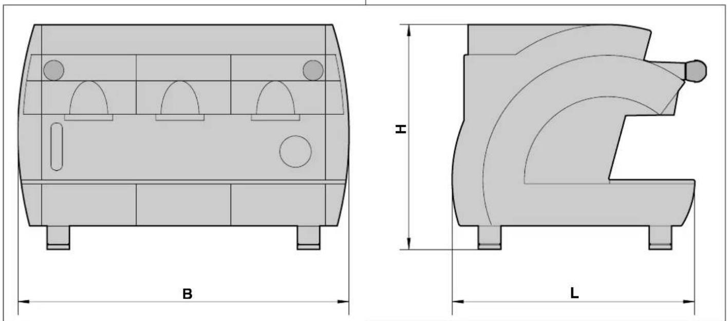
Fig.4.01
| 2 groups | 3 groups | 4 groups | ||
| Dimensions B 760 970 1180 | ||||
| H 500 500 500 | ||||
| L 540 540 540 | ||||
| Weight k | g | 70 90 110 | ||
| Boiler capacity | L 13 | 21 | 28 | |
| Boiler resistance absorbed power | ||||
| 240 / 415 V 3 N ~ | W | 4760 | 5950 | 7140 |
| 230 / 400 V 3 N ~ | W | 4370 | 5465 | 6555 |
| V 120 ~ | W | 4760 | 5950 | 7140 |
| ECO Max boiler resistance absorbed power | ||||
| 240 / 415 V 3 N ~ | W | 3170 | 3950 | 4750 |
| 230 / 400 V 3 N ~ | W | 2900 | 3640 | 4360 |
| V 120 ~ | W | 3170 | 3950 | 4750 |
| Pump motor | W | 165 | 165 | 165 |
| Overall absorbedpower | ||||
| 230-240/400-415 V 3 N ~ | W | 5200 | 6200 | 7200 |
| Gas heating | Kcal/h | 1700 | 2500 3400 | |

5 - INSTALLATION
A. MAINS SUPPLY
B. DISCHARGE DUCTS
C. GAS DUCTS
D. PROTECTION SWITCH
E. PURIFIER
F. BOILER SUPPLY TAP
G. DRIP BOWL
H. GAS VALVE
I. POWER CABLE
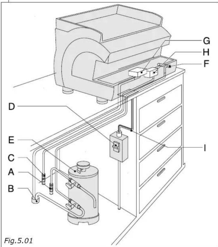
Before proceeding with installation check that:
- there are no bumps, signs of knocks or deformities.
1 there are no damp patches or marks which could lead one to assume that the packaging has been exposed to the elements
2 there are no signs of tampering
Once one is satisfied that transportation has been correctly effected proceed with installation.
Proceed with installation following the instructions according to the sequence as described below.

5.1 WATER CONNECTION

Important: The machine must be supplied with water of over 8^ F hardness.
The installation of a water softener is recommended for the machine water supply.
Check that the water mains to which connection is to be made supplies drinking water.
- Connect purifier (E) to the water mains (A).

NB: before connecting the purifier to the machine, wash out thoroughly until the water becomes clear, then proceed to connect the purifier to the machine.
- Connect the drain cup (G) to the drainage pipe (B)
- Should the mains pressure be higher than 5 bar a pressure reducer balanced for high pressure should be installed (device in which any mains pressure increase does not effect the output pressure).

5.2 ELECTRICAL CONNECTION

Important! Before proceeding with electrical connection it is necessary to check to ensure that the voltage rating corresponds with that indicated on the CE plate and on the connection plate on the power supply cable.
Check to ensure that the electrical supply line is able to support the machine load (see chap. 4 – technical features table).
Connect to an earthing socket which complies with current legislation.
Check that the power supply cable is efficient and that it complies with national and European safety standards.
The user must undertake to power the machine protecting the power line using a suitable safety switch (cut-out) that complies with the legislation in force in the actual country itself.
Connect the power cable (1) to the electric line using a plug, or in the case of fixed installation, using a multi-polar switch (D) for mains separation, with a contact distance of at least 3 mm.
For voltage change refer to the diagram shown on the general mains switch box.
The yellow-green coloured cable MUST be connected to the room's earthing system.

5.3 GAS CONNECTION
Connect valve (H) to duct (C) using a rubber hose (in compliance with current standards) and suitable hose clamps or use the connection supplied for stainless steel hose (as indicated in figure in section 8 "Gas adjustment".

6 - START UP
- Tap
- Hot water outlet button
- Hot water outlet switch
- Machine on indicator
- Gas on/off valve
- Main switch
- Right vaporiser tap
- Left vaporiser tap
- Cup-warmer switch
- Boiler/pump pressure gauge
- Optional cappuccino maker
- Boiler level indicator
- Left vaporiser tap
- Right vaporiser tap
- Hot water outlet pipe
- Unit D control keyboard
- Unit E control keyboard
- Optional dose-counter display
- E delivery indicator
- D delivery led
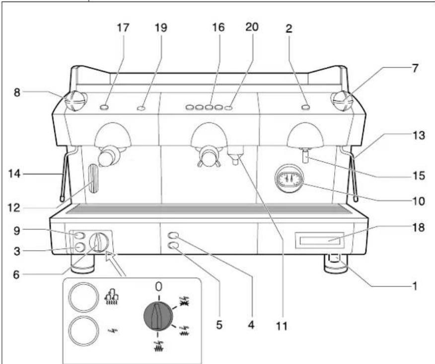
Fig.6.01
Once the water, gas and electrical connections have been made, proceed to start up the machine.
Open the mains water supply tap (A). Close the protection switch (D)
Position the machine main switch (8) to position the machine on indicator will come on (3).
The auto-levelling device will come into operation so that the water reaches a normal level in the boiler (12).
Position the main switch (6) to position for operation at normal power or to position for operation at full power, thereby powering the resistances.
Wait for the pressure to reach its operational pressure 1.1÷1.3 atm checking the boiler pressure on the gauge (10).
Should the machine fail to stabilize on the indicated values it is necessary to calibrate the pressure switch as described in paragraph 6.2.
In the event of a machine featuring a gas heating system, it is necessary to switch on the gas by operating the gas valve (4) after operating the main switch (6), keeping the piezoelectric switch pressed (5) until the gas remains on.
Then check the pressure on the pump gauge (10) putting a unit into operation with filter holder engaged filled with ground, dosed and pressed coffee in order to achieve an effective working pressure of 8/9 atm.
Should re-calibration of the pump pressure be necessary this operation should be undertaken as indicated in paragraph 6.3.
The machine is now ready for use.

IMPORTANT
Do not press the hot water delivery switch or button (2) before the correct working temperature of 1.1 atm is reached, as indicated on the boiler gauge (10).

6.1 LONG COFFEE GIGLEUR
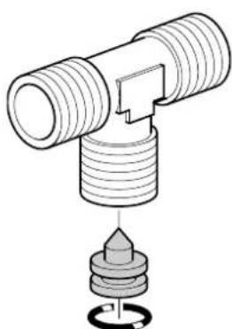
The machine is fitted with a gigleur (1 per unit) with a clearance of 0.6 mm (Cod.26G0074/01).
For greater coffee delivery speed, in the case of long coffees, no.2 gigleurs are also included with the machine (complete with seals) with a clearance of 0.8 mm (Cod.26G0073/01).
The gigleur is located in the exchanger supply fitting (1 per group).
natural_image
Technical illustration of a mechanical assembly with threaded pipe and base component (no text or symbols)Fig.6.02

6.2 PRESSURE SWITCH ADJUSTMENT
The pressure switch shown in the figure acts to keep the boiler pressure constant by engaging or de-activating the electrical heating resistance.
This pressure switch is already calibrated to 1.1-1.3 bar during the initial machine testing stage, but should a different working pressure be required, it is possible to vary the operational field of the pressure switch using the regulation screw (U); pressure reduction results in a reduction in temperature, whilst increasing the pressure will also increase the water temperature.
The regulation direction is shown in the figure and on the pressure switch itself.
The pressure varies by 0.1 atm for every complete screw turn,

Warning: Disconnect the electricity supply before undertaking this operation.
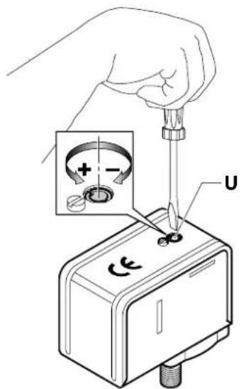
Fig.6.03

6.3 PUMP PRESSURE CALIBRATION
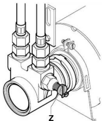
Insert the filter holder into the unit filled with regularly ground, dosed and pressed coffee.
Switch on the unit switch or the unit control keyboard (16) and read the pressure on the pump pressure gauge (10).
NB: The correct pressure is of 8-9 atm.
Should the pressure indicated on the pressure gauge be incorrect, turn it clockwise to increase the pump pressure and anti-clockwise to reduce the pressure.
Once adjustment is complete check pump calibration by delivering one or more coffees.
Z= Pump pressure adjustment screw.
natural_image
Technical line drawing of a mechanical valve assembly with no visible text or symbolsFig.6.04

Warning !!
When the machine is new the filter-holder sump may not be aligned (perpendicular to the machine itself) as shown in the figure at the side, however this does not effect the efficient function of the same.
After a short period of use the sump will gradually settle into a correct position.
A = Position of closed filter-holder with new machine.
B = Position of closed filter holder with machine after a short period of use.
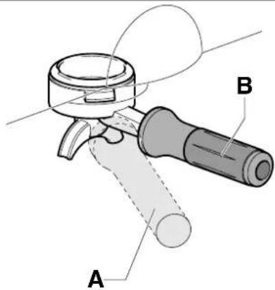
Fig.6.05

IMPORTANT: N°2 under-tile packings with are thinner (8.1mm) than that fitted as standard are included. These packings may be used in the event of difficulty with insertion of the filter holder.
6.4 FILTERS FOR COFFEE MACHINE
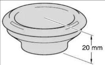
Depending on the quantity of coffee ground, the appropriate filter must be as shown below to avoid that, once the coffee has dripped out, the leftover powder remains attached to the nozzle.
natural_image
Technical drawing of a circular mechanical component with a 20 mm dimension label (no other text or symbols)NF08/002/B
1 coffee cup of 5,5 gr. ÷ 6,5 gr. pod for 1 coffee barley pod for 1 dose
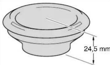
NF08/004/B
1 coffee cup of 6 gr. ÷ 7 gr.
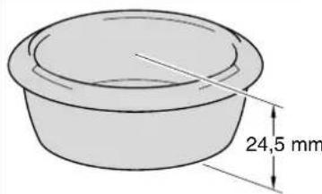
NF08/005/B
2 coffee cups of 12 gr. ÷ 14 gr.
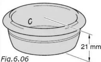
NF08/009/B
Double pod for 2 coffees The filter may be recognised by the letter "C" printed inside
6.5 REPLACEMENT OF THE THERMOSTAT TO REDUCE THE COFFEE DISPENSING GROUP TEMPERATURE (OPTIONAL).
Remove cup heating bowl (1). Disconnect group thermostat (2) (Code DM1561 – T 103°C) and replace it with the lower temperature thermostat (Code DM1736 – T 98°C), included in the machine equipment.
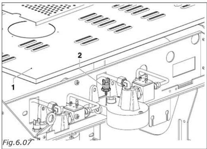
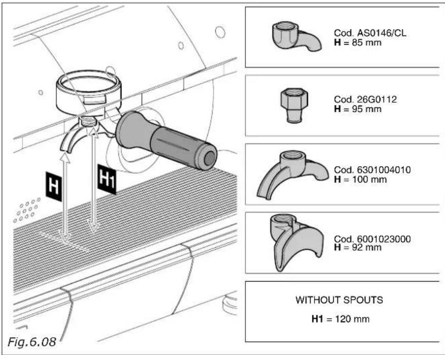
6.6 SPOUTS INCLUDED IN THE SUPPLY.
No. 4 spouts are supplied with the machine to dispense one or two coffees.
The figure (beside) shows the different distances from the cup-holding tray (H), depending on the different types of spouts fitted on the filter holder.
7 - FUNCTION / USE AND PROGRAMMING
INTRODUCTION
The programming software permits the checking of the following operations:
- handling of 2-3-4 coffee units
- simultaneous function of both coffee and tea units
- cappuccino/milk function
- volumetric check on coffee measures
- timed tea measure check
- simulated measure programming
- filling level check and control
- system supervision through alarms
- continuos, delivery time-out and further functions
- serial connection with accounting devices
- 16 X 2 LCD display (not rear-lit) for functional state display.
Important: the last selection made always appears on the display
7.1 COFFEE MEASURE PROGRAMMING
The measured amounts of coffee may be modified (by means of volumetric checking) and memorized as follows:
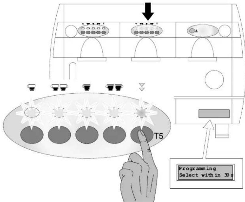
- press key T5 (of keyboard relative to group 1) and keep pressed for over 5 seconds and check that all the keyboard leds come on. In which case, (by operating on the keyboard relative to group 1) all the units will be programmed, while by pressing key T5 of another unit, only the programming of the unit on which one is operating is possible.
IMPORTANT !! The settings made on unit 1 (operating on the first keyboard) will be automatically copied on to all the other units.
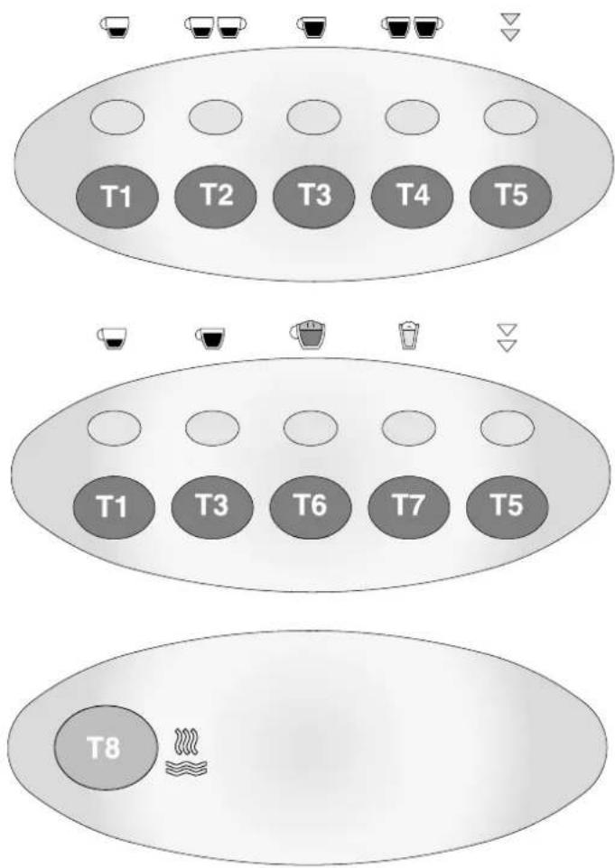
Keyboard symbols:

natural_image
Three identical black-and-white cups of varying shades, arranged vertically (no text or symbols)T1 Single espresso coffee
T2 Double espresso coffee
T3 Single long coffee
T4 Double long coffee

T5 Programming/continuos
T6 Cappuccino
T7 Milk
T8 Tea (hot water)
flowchart
graph TD
    A["Top Row: T1-T5 with 5 cups"] --> B["Left Row: T1-T5 with 5 cups"]
    B --> C["Right Row: T1-T5 with 5 cups"]
    C --> D["Bottom Row: T8 with steam icon"]
    style A fill:#f9f,stroke:#333
    style B fill:#ccf,stroke:#333
    style C fill:#cfc,stroke:#333
    style D fill:#fcc,stroke:#333
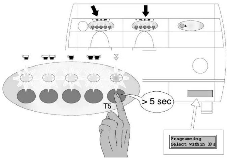
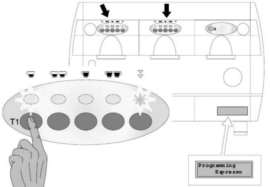
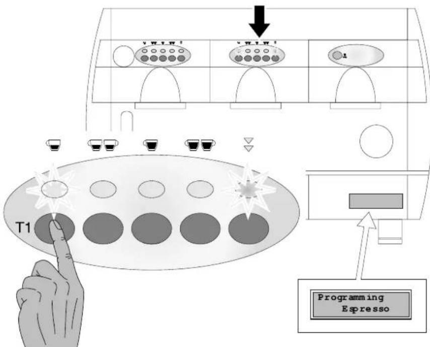
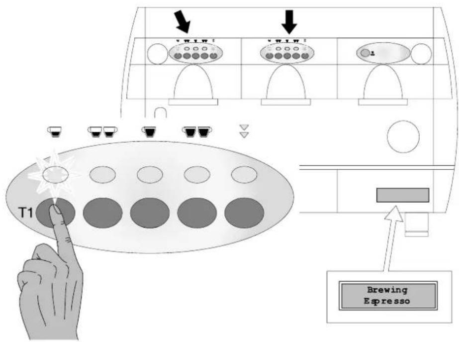
Press the key corresponding to the measure to be programmed (key T1 for example) within 30 seconds (programming time-out).
The led relative to T5 will remain on, on all keyboards and the led relative to the measure being programmed will also come on (on all the keyboards). During this state and for the entire coffee measure programming time duration, the solenoid valve and pump are activated.
Note: If none of the keys are pressed within 30 seconds, it will automatically escape from programming mode.
On pressing key T1 coffee delivery begins, once the required amount of coffee is obtained press key T1 again or any other of the keys of the unit keyboard in order to suspend coffee delivery. The new impulse value of the measure is thereby memorized on the EPROM.
Both the solenoid valve and the pump are de-activated thereby suspending product delivery and all the keyboard leds go out.
To proceed with a new programming operation of other coffee measures T2-T3-T4 (providing that the programming time out time of 30 sec is not exceeded) simply repeat the same operations with the same sequence as undertaken for key T1.
Press key T5 to immediately escape from the programming stage.
IMPORTANT: Should the "PRE-INFUSION" function be active (see par. 7.5). Wait until the pre-infusion function is complete before stopping delivery in progress.
NOTE: During the programming of a unit the function of the other units is deactivated as well as tea dispensing.
To programme the other units, press the specific programming key of each unit and carry out the same operations as undertaken on unit 1. In this case any variations in the measures are activated only on the unit on which one is actually working.
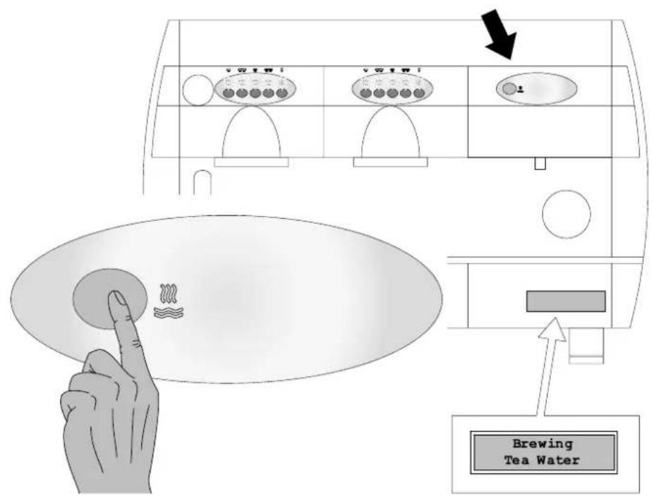
7.2 TEA MEASURE PROGRAMMING (HOT WATER)
It is possible to modify the timed tea measures according to the following sequence:
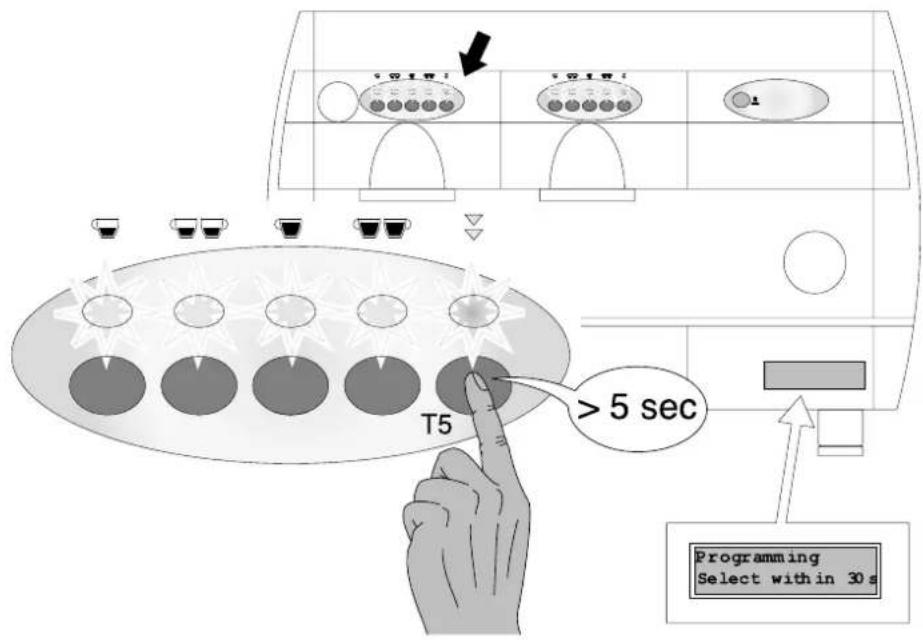
Press key T5 of coffee unit 1 and keep pressed down for over 5 seconds and check that all the keyboard led indicators come on.
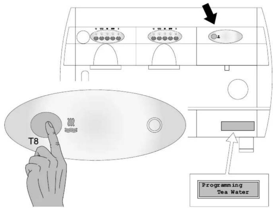
Press the T8 tea key within 30 seconds (programming time-out).
This begins the tea water delivery operation.
Once the required measure is obtained press T8 again to suspend water delivery. In this way the new tea water delivery time is memory and all the keyboard leds go out.
Press key T5 again to immediately escape from the programming phase.
7.3 COFFEE DELIVERY
On pressing the corresponding key T1-T2-T3 or T4, the corresponding delivery solenoid valves are activated for the time necessary to obtain the required amount of product as previously programmed (volumetric check).
The LED relative to the selected measure remains on for the entire coffee delivery time.
The delivery in progress may be suspended before actually reaching the desired programmed product quantity by pressing any of the measure keys present on the keyboard of the unit used for product delivery.
It is also possible to obtain simultaneous coffee delivery from all the machine units.
7.4 CONTINUOUS COFFEE MEASURES
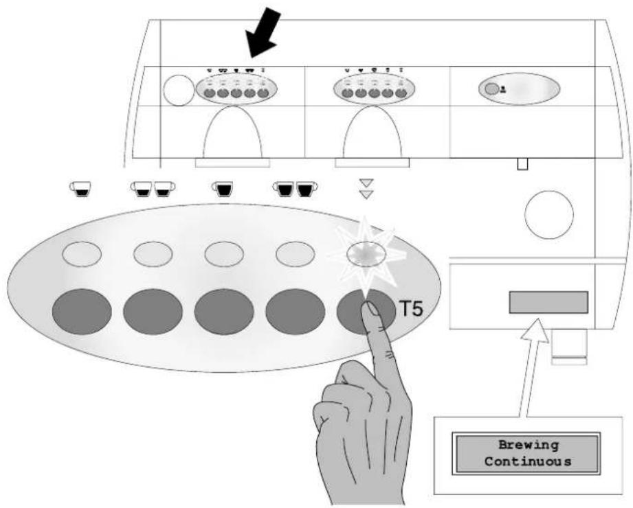
For continuous coffee measure delivery press key T5 from the keyboard corresponding to the unit on which one wishes to operate.
The LED corresponding to key T5 will remain on for the entire delivery operation.
IMPORTANT! Avoid keeping it pressed for more than 5 seconds or it will enter the programming mode.
Coffee delivery will continue until measure stop by pressing key T5, or on obtaining the maximum amount of product which can be obtained through volumetric control (6000 impulses) or by means of delivery Time-out function.
IMPORTANT ! The start of the relative "continuous" cycle occurs on the release (within 5 seconds) of key T5 and not on pressing of the same. While the STOP function may be obtained by pressing it a second time.
7.5 SPECIAL FUNCTIONS
It is possible to engage or deactivate certain special functions such as PRE-INFUSION, MIXED TEA and WASHING ALARM which we shall describe below:
WASHING ALARM
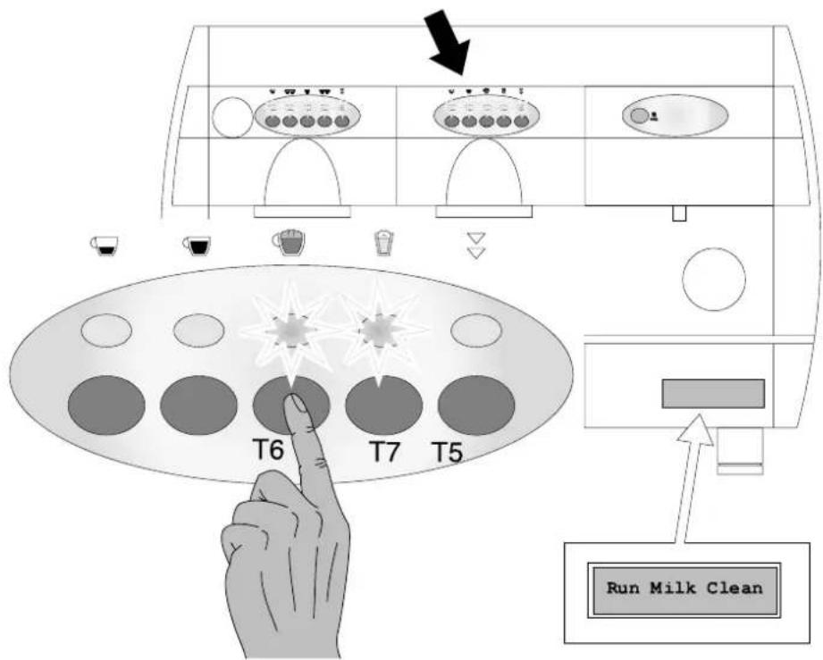
This function acts to indicate, after 10 minutes from the start of the delivery of the cappuccino or milk, the following signal "Run Milk Clean" and the alternating flashing of the LEDs corresponding to keys T6 and T7 which indicate that a milk or cappuccino has been prepared and the milk section therefore needs to be cleaned. To temporarily cancel the alarm function press key T6 or T7.
CAPPUCCINO MACHINE CLEANING
Cleaning to be undertaken when the "Run Milk Clean" message appears with the alternating flashing of the LEDS corresponding to keys T6 and T7.
Take a 1 litre container full of cold water. Remove the milk suction pipe from the container and place inside the container itself.
Press keys T7 and T5 at the same time (on the keyboard activated for the "service" functions) this engages the milk delivery function, the water flow will clean the cap-puccino machine.
Once all the water has been suctioned, stop delivery by pressing key T7.
PRE-INFUSION
Our software permits measure configuration so that the relative delivery of the COFFEE measures through volumetric control is preceded by pre-infusion. Delivery of the coffee measure after time 1 (ON) is suspended for a time 2 (OFF) and is then resumed for the completion of selection.
On pressing one of the volumetric control measure keys, the normal delivery cycle is preceded by a short timed water jet in order to dampen the coffee pellets before actual delivery stage.
This function ensures the optimum use of the coffee pellets.
MIXED TEA (HOT WATER)
On the engagement of this function the water delivered is mixed with cold water on entry in the boiler thereby ensuring constant delivery at a temperature of about 96°C. If this function is not engaged water is delivered at a temperature of about 100°C and is highly vaporized.
ENGAGEMENT/DEACTIVATION
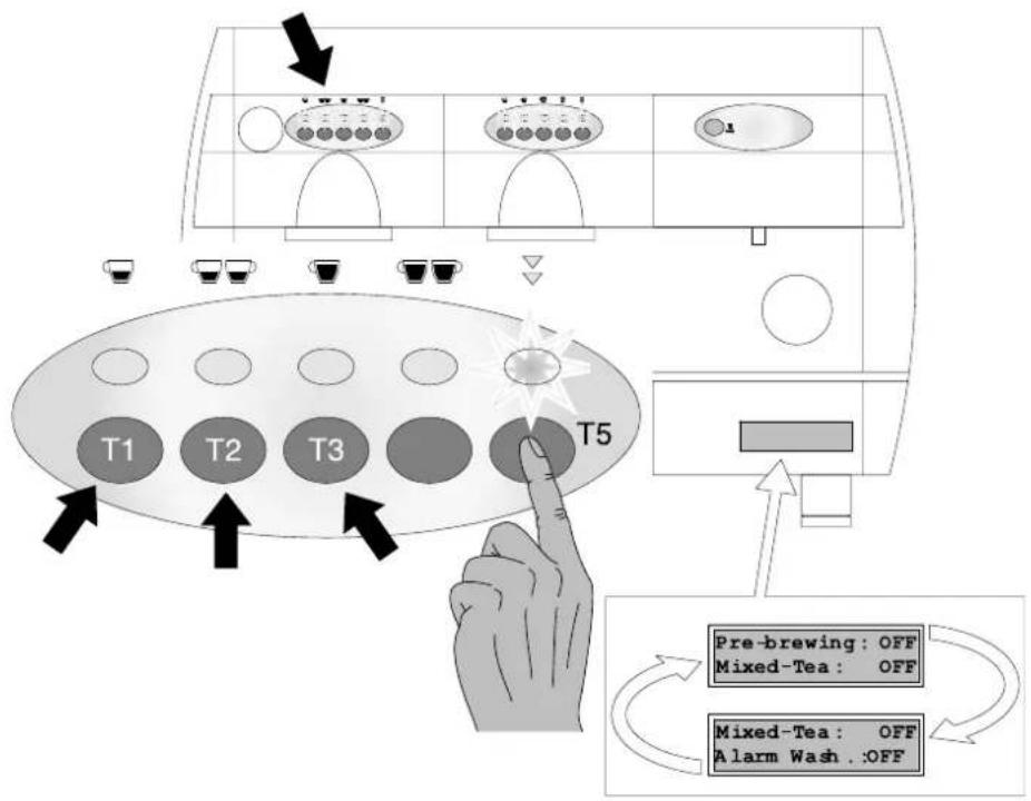
Start the machine by pressing the main switch keeping key T5 of unit 1 pressed and wait for the led relative to key T5 to begin flashing.
Press keys T1-T2 and T3 in order to engage or deactivate the PRE-INFUSION, MIXED TEA and WASHING ALARM functions.
T1 KEY LED ON : PRE INFUSION: ON T2 KEY LED ON : MIXED TEA: ON T3 KEY LED ON : WASHING ALARM: ON
To escape from this condition and return to normal functions press key T5 again.
7.6 TEA DELIVERY
On pressing key T8 the corresponding solenoid valve is engaged thereby beginning hot water delivery.
On START a timer is activated which interrupts the water delivery on reaching the time set during the programming stage. The simultaneous delivery of tea or coffee is possible.
It is possible to interrupt delivery function in progress before the programmed time is reached by pressing key T8 again used for product delivery.
flowchart
graph TD
    A["Pre-brewing: OFF"] --> B["Mixed-Tea: OFF"]
    B --> C["Mixed-Tea: OFF\nAlarm Wash.:OFF"]
    C --> D["T1"]
    C --> E["T2"]
    C --> F["T3"]
    D --> G["T5"]
    E --> G
    F --> G
7.7 CAPPUCCINO AND MILK FUNCTION
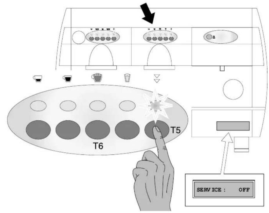
It is possible to set the CAPPUCCINO and MILK function on keys T6 and T7 on group 2,3, or 4.
IMPORTANT: The function can be set on only one keyboard at a time, on unit 2, 3 or 4.
ENGAGEMENT/ DEACTIVATION
In order to set the function on the keyboard of unit 2, for example, keep key T5 pressed down and the corresponding LED will begin flashing until the wording "SERVICE OFF" appears on the display.
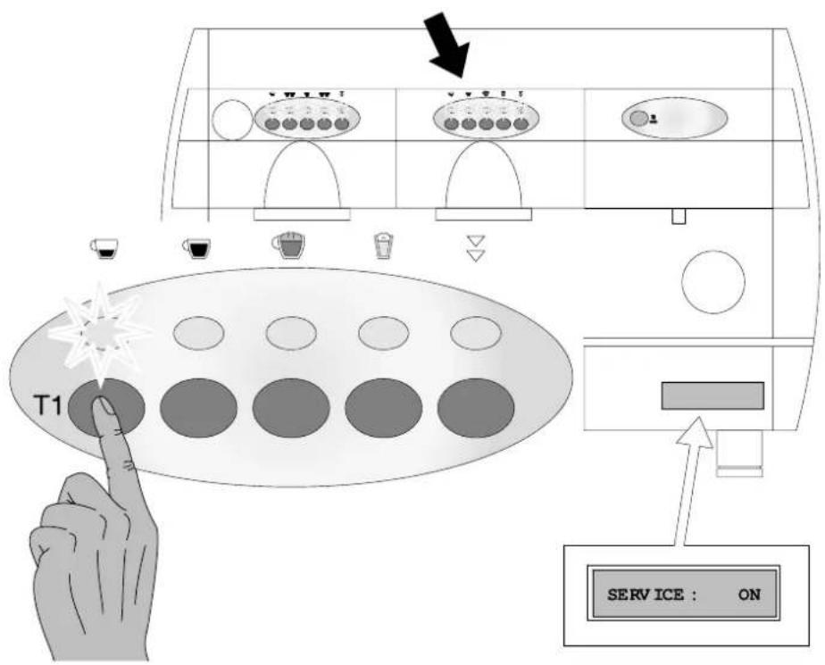
Press key T1 of keyboard 2 in order to engage the Cappuccino/milk function on the 2^nd unit.
T1 KEY LED ON : SERVICE: ON
Proceed in the same way to engage this function on the keyboard of another unit.
7.8 CAPPUCCINO DELIVERY AND PROGRAMMING
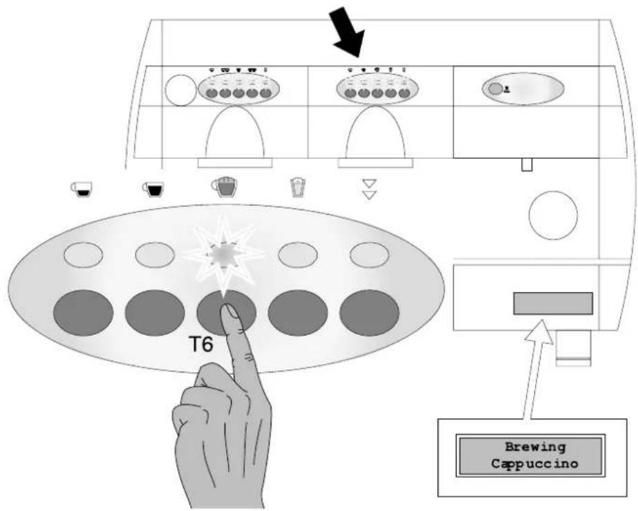
When engaged key T6 will determine the activation of the solenoid valve and pump according to the value set during programming.
To programme the cappuccino function, proceed in the same way as for coffee with the only difference being that at the end of the volumetric delivery of the coffee, the timed milk delivery BEGINS SEPARATELY. Once the desired quantity is obtained stop delivery using key T7.
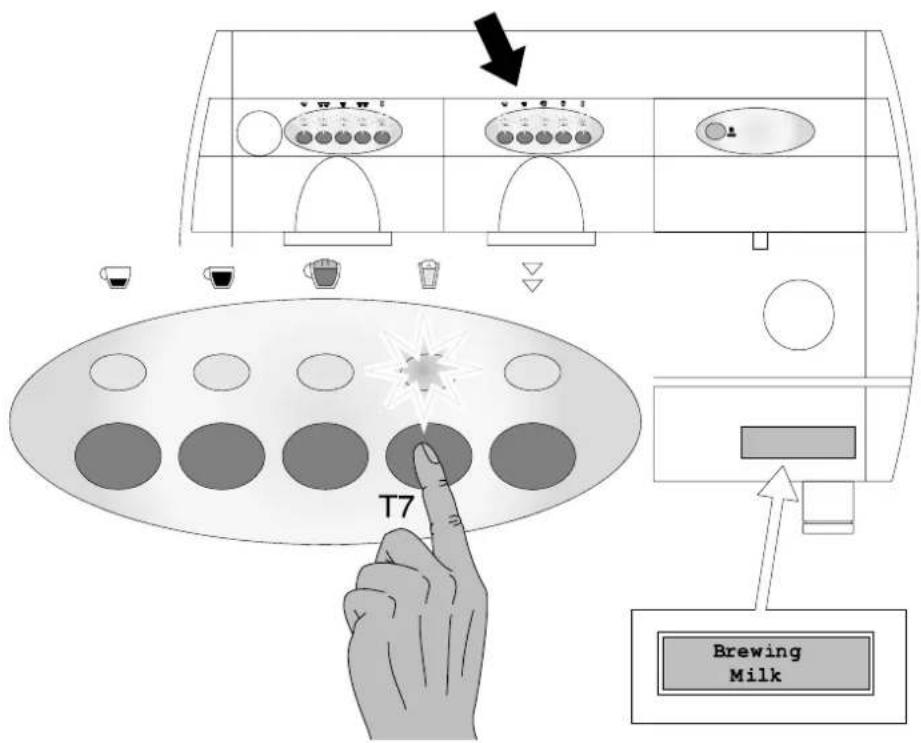
7.9 MILK PROGRAMMING AND DELIVERY
Key T7 when engaged determines the activation of the solenoid valve according to the value set during programming. The programming of this function is the same as that for TEA.
7.10 FURTHER FUNCTIONS ON MACHINES EQUIPPED WITH DISPLAY
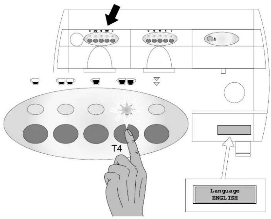
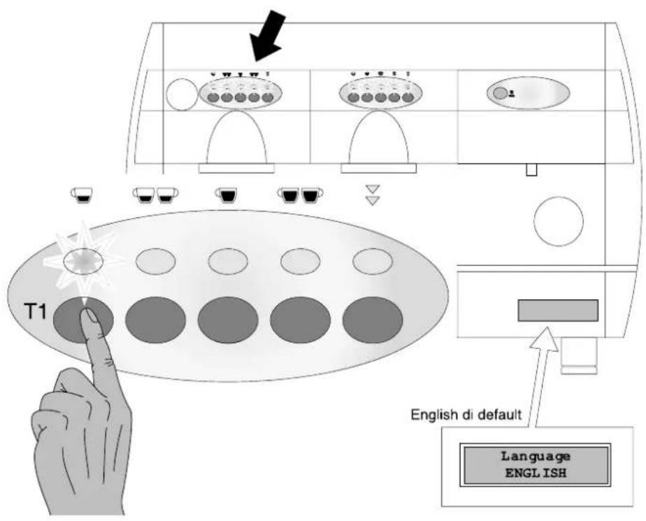
LANGAUGE SELECTION
In order to select the consultation language, on switching on, press key T4 and keep pressed.
Press key T1 several times to select the desired language, press T4 again to confirm selection.
CONSUMPTION READING
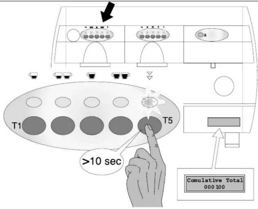
It is possible to read the consumptions that have been made following the instructions indicated below.
Press key T5 (of 1 ^st unit only) and keep pressed for over 10 seconds. The display will show the dispensing operations undertaken: press key T5 again to escape from this condition.
By pressing key T1 (forward) or T2 (back) it is possible to consult the various memorized consumption values.
On pressing key T1 of unit 1 on goes on to the consumption values of the keys of unit 2 and so on in succession.
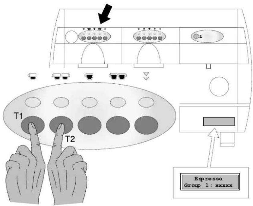
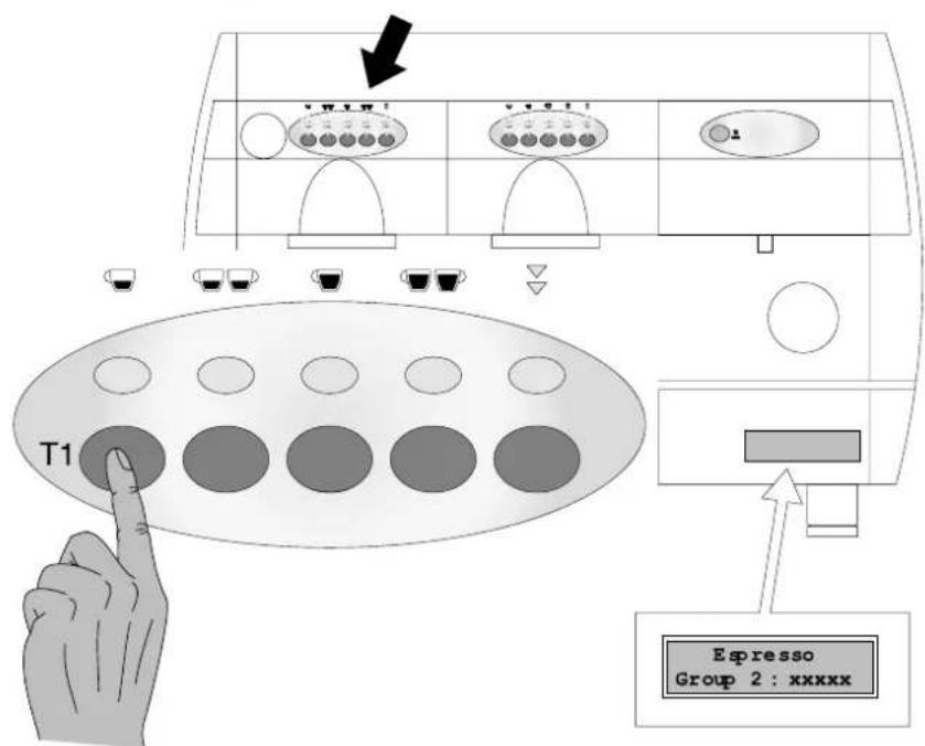
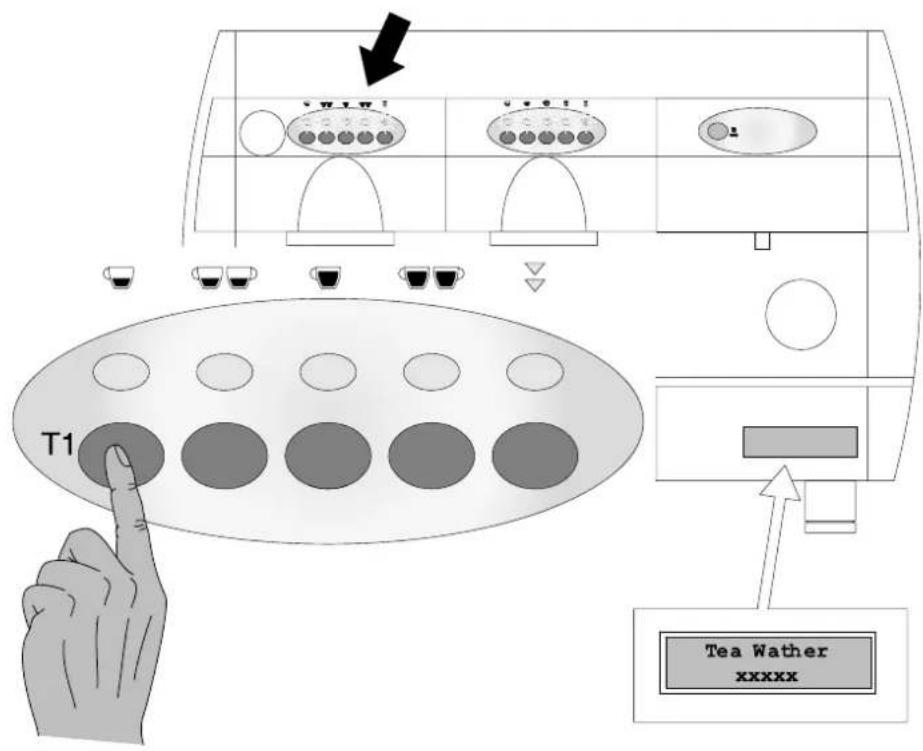
After visualization of the data of the last coffee unit also, on pressing key T1 it is possible to obtain a reading of the number of TEA dispensing operations made.
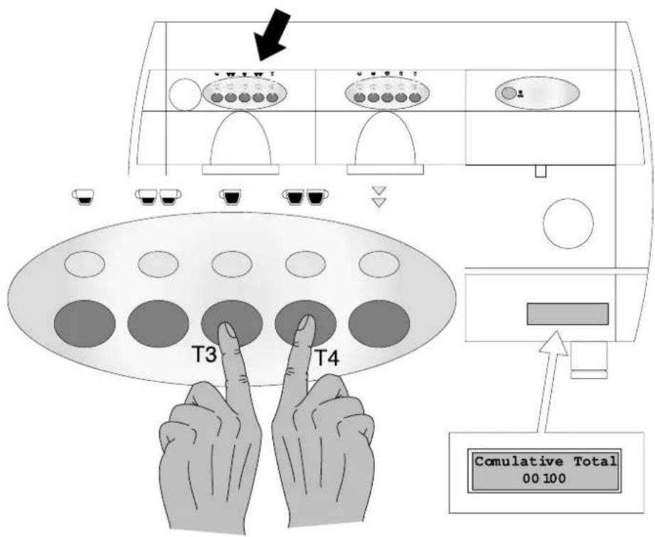
To cancel the totals of the individual consumptions (but not the "total cumulative" data), press keys T3 and T4 of unit 1 for 3 seconds in the condition in which "CUMULATIVE TOTAL" is displayed.
7.11 ALARM CONDITION
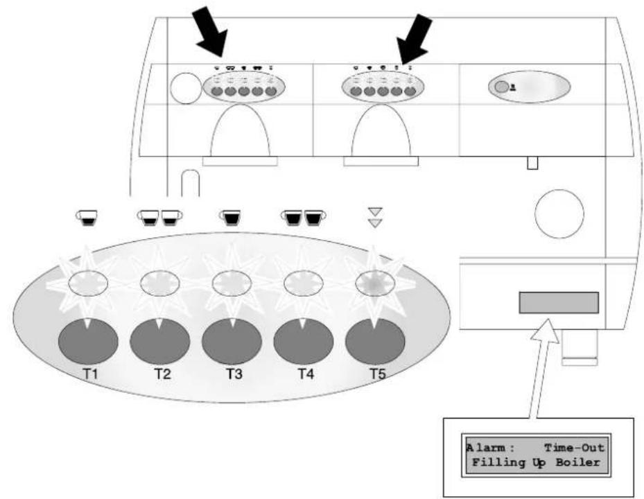
This alarm condition occurs whenever the water level is too low or the level probe remains uncovered. In such a case the keyboard leds flash and an alarm message appears on the display.
The filling stage is automatically engaged and to cancel the alarm conditions switch the machine off and then on again.
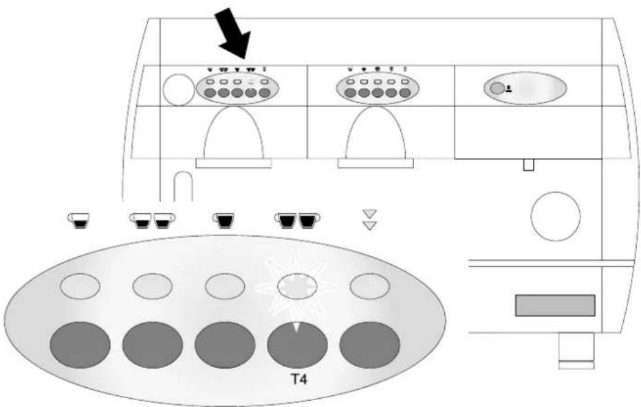
Lack of volumetric counter impulses
On starting a volumetric control coffee cycle, the correct function of the volumetric counter is checked by the reading of the number of impulses sent by the same to the micro-controller.
Should no impulses by recorded for a period exceeding 5 seconds the LED relative to the selected measure begins flashing (ie. the led relative to key T4).
After one minute in which no impulses are recorded (volumetric counter time out), the measure underway is automatically stopped.

8 - PURIFIER REGENERATION
Fig. 8.01
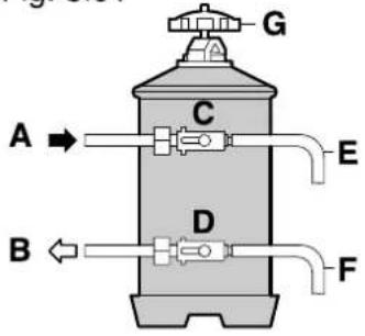
Fig. 8.02
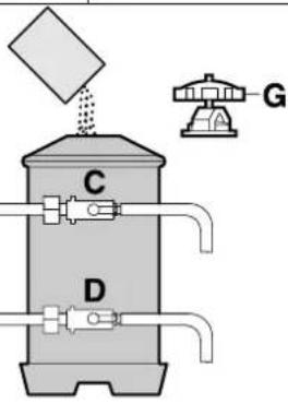
Fig. 8.03
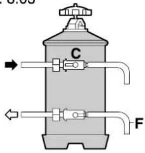
Fig. 8.04
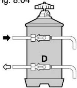
A WATER INLET
B WATER OUTPUT
C INLET TAP LEVER
D OUTPUT TAP LEVER
E DEPRESSURIZER PIPE
F REGENERATION TUBE
G COVER KNOB

IMPORTANT : Regenerate the purifier at the intervals listed below:
HARDNESS °F 8 LITRE PURIFIER 12 LITRE PURIFIER
From 00 to 20 re
generation after 1100 l. re
generation after 1600 I
From 21 to 30 re
generation after 850 l. re
generation after 1250 l.
From 31 to 40 re
generation after 650 l. re
generation after 950 l.
From 41 to 60 re
generation after 450 l. re
generation after 650 l.
- place the empty 2 litre container under pipe E.
- shift levers C and D from left to right as shown in fig.8.2 and remove the cover by loosening knob G, pour in 1.5 kg of sodium chloride (coarse cooking salt) into the 8-litre purifier and 2 kg into the 12-litre type.
- Replace the lid and shift lever from right to left as shown in fig.8.3 and allow the salted water to drain out of pipe F until the water is fresh.
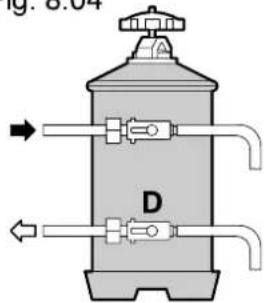
- Shift lever D from right to left as shown in fig.8.4

NB: These regeneration instructions are valid only providing the purifier is as that indicated in the figures. Should it fail to correspond proceed as indicated in the instructions attached to the purifier itself.

9 - GAS ADJUSTMENT
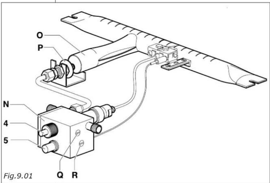
4 GAS- ON-OFF VALVE
5 PIEZOELECTRIC IGNITION
N GAS REGULATOR
O GAS INJECTOR
P RING NUT
Q MINIMUM ADJUSTMENT SCREW
R PRESSURE ADJUSTMENT SCREW
GAS INJECTOR (pos.0)
Category III 1a2H3 + 2 GR machine 3 GR machine 4 GR machine
G20 (methane)
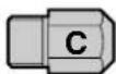
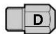
G30 (liquid gas)
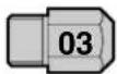
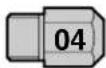
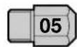
G110 (town gas)
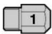
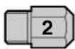
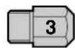
The machine is set up for being supplied with methane gas (G20), this means that the gas injector (O) and the gas regulator (N) are calibrated for methane gas.
For operation with GPL gas (liquid gas G30) or town gas, the gas injector (O) must be replaced with the injector enclosed with the machine (see gas injector table).
To light the gas burner keep the gas n-oiff valve button (4) pressed down in order to allow the gas to flow to the burner, then operate the piezoelectric ignition push-button (5).

NB: The on-off valve button must remain pressed down for a few seconds to allow the thermo-couple to operate.
Adjust the air flow by means of the air adjustment ring nut (P) turning clockwise to reduce the flow and anti-clockwise to increase it, so as to obtain a blue flame (avoid long or excessively oxidising flames to avoid damaging the boiler).
Wait for the boiler to reach an operating pressure of 1.1÷1.3 atm and for the flame to be reduced to a minimum. If the gas regulator (N) requires calibration, proceed as follows: turn the minimum adjustment screw (Q) clockwise to reduce the flame and anticlockwise to increase it.
To increase or reduce maximum pressure in the boiler, turn the pressure adjustment screw ^ clockwise to decrease the pressure and anti-clockwise to increase it.

10 - MAINTENANCE AND USEFUL ADVICE
In order to ensure that the spouts (B) are kept clean and free of any coffee deposits which may jeopardize yield, we advise that before starting work in the morning that you put filter holder (D) in with empty filter (while machine is hot) and operate the unit several times.
In this way any coffee dust which may have been deposited between the metal filter (B) and the metal filter holder (A) are removed. This operation must be repeated every day.
Frequently check the filter holes (C) and remove any deposits.
Should the water have been left in the ducts for a long time, it is necessary to allow some water to flow through them in order to remove any deposits.
It is a good idea to rinse the filters (C) and filter holders (D) every day in hot water, or even better, place them in hot water and allow to soak for the whole night in order to dissolve any greasy coffee deposits.
It is advisable to leave the filter-holder cups inserted with the coffee dregs for the entire working day to ensure that the filter-holder is always at optimum temperature.
Do not cover the cup-warmer level with any fabrics or cloths etc. Do not use any abrasive or corrosive products for cleaning the bodywork.
The steam nozzles must be cleaned immediately after use in order to prevent the risk of the formation of any scale which may block the holes and to ensure that any drinks made subsequently do not absorb any unpleasant odours.
A SPOUT HOLDER
B SPOUT
C FILTER
D FILTER HOLDER
E SEAL
F UNIT COFFEE
G CENTRAL SCREW
H ALLEN SCREWS
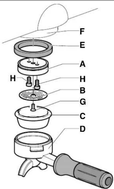
Fig.10.01

Weekly cleaning operations
Cleaning of the unit and spouts: place a teaspoon of specific coffee machine washing powder into the blind filter supplied with the machine and apply to the unit to be cleaned using the filter-holder. Press the unit delivery control button as for a normal coffee dispensing operation. Suspend delivery after 30 seconds and then repeat the operation 3-4 times. Rinse out the unit using a normal filter and then undertake a few dispensing operations using water only. Then prepare a coffee in order to eliminate any unpleasant odours.

Below-cup seal replacement
Seal (E) needs to be replaced in the event that coffee leakage is noted between unit (F) and filter-holder (G), or in the event that on closing filter holder (D) the unit centre is greatly exceeded.
Remove the spout (B) by loosening the central screw (G).
Remove the spout holder (A) by loosening the two Allen screws (H).
Then proceed to remove seal (E) using a screw driver.
After removing the seal undertake to clean the slot and then re-assemble the new seal taking care to insert it with the chamfered part turned upwards towards the unit itself.
11 - TROUBLE SHOOTING
| PROBLEM CAUSE REMEDY | ||
| Machine switch off 1. Mains switch off2. Machine switch off3. Incorrect electrical mains connection 3. | ch off | 1. position the machine switch position ON2. position the machine switch position 1contact specialized personnel in order to check the connection |
| No water in boiler 1. Mains ta | p closed 1. o2. Clogged pump filter 2. re3. Motor driven pump not in operation 3. | pen the mains ta pplace the filtercontact specialized personnel |
| No unit delivery | 1. mains ta p closed 1. o2. motor driven pump out of order3. clogged qia leur4. burnt control box fuse5. unit solenoid valve out of order6. unit switch out of order | pen the mains ta p2. contact specialized personnel3. contact specialized personnel4. contact specialized personnel5. contact specialized personnel6. contact specialized personnel |
| Steam fails to come out of the nozzle | 1. too much water in boiler2. damaged resistance3. clogged sprayer element4. resistance saver engaged | 1. seepcific problem2. contact specialized personnel3. clean the s prayer element4. reinsert the resistance |
| Too much water in the boiler | 1. the motor driven pump remains engaged2. perforated exchanger3. automatic char ge solenoid valve blocked | 1. contact specialized personnel2. contact specialized personnel3. contact specialized personnel |
| Signs of water leakage on bench | 1. dirty drain tray2. drainage pipe clogged or detached3. other leaka ge | 1. clean the tr y2. replace the drainage pipe3. contact specialized personnel |
| Wet coffee drags | 1. Grinding regulated too fine2. Unit still cold3. Solenoid valve fails to discharge | 1. Ad just grinding value2. wait for the machine to reach the correct tem perature3. contact specialized personnel |
| Coffee dispensing too slow | 1. grinding element set too fine2. dirty filter-holder3. clogged unit4. gig leur or solenoid valve partially clogged | 1. Adjust the grinder2. replace the filter and undertake more frequent filter-holder cleaning g3. contact specialized personnel4. contact specialized personnel |
| Coffee dispensing too fast | 1. grinder is re gulated too large | 1. regulate the grinding g |
| Coffee delivered cold | 1. Lime scale present on the exchangers or the resistances2. oxidized pressure switch contacts3. defective electrical connection4. partially burnt out resistance | 1. contact specialized personnel2. contact specialized personnel3. contact specialized personnel4. replace the resistance element |
| Coffee delivered too hot | 1. incorrect pressure switch calibration 1. | re qulate the pressure switch by means of the relative screw(chap. 6.2) |
12 - MACHINE DISMANTLING
To dismantle the machine we recommend that it is dismantled and the parts separated according to the type of materials involved (plastic, metal, etc). The parts separated in this way are then to be sent to the relative specialized disposal companies.
LEGENDA COMPONENTI - COMPONENTS LIST - LEGENDE BAUTEILE
flowchart
graph TD
    A["BLU BLUE"] --> B["BRIDGE GRAY"]
    A --> C["BRIDGE GRAY"]
    A --> D["BRIDGE GRAY"]
    A --> E["BRIDGE GRAY"]
    A --> F["BRIDGE GRAY"]
    A --> G["BRIDGE GRAY"]
    A --> H["BRIDGE GRAY"]
    A --> I["BRIDGE GRAY"]
    A --> J["BRIDGE GRAY"]
    A --> K["BRIDGE GRAY"]
    A --> L["BRIDGE GRAY"]
    A --> M["BRIDGE GRAY"]
    A --> N["BRIDGE GRAY"]
    A --> O["BRIDGE GRAY"]
    A --> P["BRIDGE GRAY"]
    A --> Q["BRIDGE GRAY"]
    A --> R["BRIDGE GRAY"]
    A --> S["BRIDGE GRAY"]
    A --> T["BRIDGE GRAY"]
    A --> U["BRIDGE GRAY"]
    A --> V["BRIDGE GRAY"]
    A --> W["BRIDGE GRAY"]
    A --> X["BRIDGE GRAY"]
    A --> Y["BRIDGE GRAY"]
    A --> Z["BRIDGE GRAY"]
    A --> AA["BRIDGE GRAY"]
    A --> AB["BRIDGE GRAY"]
    A --> AC["BRIDGE GRAY"]
    A --> AD["BRIDGE GRAY"]
    A --> AE["BRIDGE GRAY"]
    A --> AF["BRIDGE GRAY"]
    A --> AG["BRIDGE GRAY"]
    A --> AH["BRIDGE GRAY"]
    A --> AI["BRIDGE GRAY"]
    A --> AJ["BRIDGE GRAY"]
    A --> AK["BRIDGE GRAY"]
    A --> AL["BRIDGE GRAY"]
    A --> AM["BRIDGE GRAY"]
    A --> AN["BRIDGE GRAY"]
    A --> AO["BRIDGE GRAY"]
    A --> AP["BRIDGE GRAY"]
    A --> AQ["BRIDGE GRAY"]
    A --> AR["BRIDGE GRAY"]
    A --> AS["BRIDGE GRAY"]
    A --> AT["BRIDGE GRAY"]
    A --> AU["BRIDGE GRAY"]
    A --> AV["BRIDGE GRAY"]
    A --> AW["BRIDGE GRAY"]
    A --> AX["BRIDGE GRAY"]
    A --> AY["BRIDGE GRAY"]
    A --> AZ["BRIDGE GRAY"]
    A --> BA["BRIDGE GRAY"]
    A --> BB["BRIDGE GRAY"]
    A --> BC["BRIDGE GRAY"]
    A --> BD["BRIDGE GRAY"]
    A --> BE["BRIDGE GRAY"]
    A --> BF["BRIDGE GRAY"]
    A --> BG["BRIDGE GRAY"]
    A --> BH["BRIDGE GRAY"]
    A --> BI["BRIDGE GRAY"]
    A --> BJ["BRIDGE GRAY"]
    A --> BK["BRIDGE GRAY"]
    A --> BL["MARRONE BROWN"]
    A --> BM["MARRONE BROWN"]
    A --> BN["MARRONE BROWN"]
    A --> BO["MARRONE BROWN"]
    A --> BP["MARRONE BROWN"]
    A --> BQ["MARRONE BROWN"]
    A --> BR["MARRONE BROWN"]
    A --> BS["MARRONE BROWN"]
    A --> BT["MARRONE BROWN"]
    A --> BU["MARRONE BROWN"]
    A --> BV["MARRONE BROWN"]
    A --> BW["MARRONE BROWN"]
    A --> BX["MARRONE BROWN"]
    A --> BY["MARRONE BROWN"]
    A --> CA["MARRONE BROWN"]
    A --> CB["MARRONE BROWN"]
    A --> CC["MARRONE BROWN"]
    A --> CD["MARRONE BROWN"]
    A --> CE["MARRONE BROWN"]
    A --> CF["MARRONE BROWN"]
    A --> CG["MARRONE BROWN"]
    A --> CH["MARRONE BROWN"]
    A --> CI["MARRONE BROWN"]
    A --> CJ["MARRONE BROWN"]
    A --> CK["MARRONE BROWN"]
    A --> CL["MARRONE BROWN"]
    A --> CDM["MARRONE BROWN"]
    A --> CDG["MARRONE BROWN"]
    A --> CEQ["MARRONE BROWN"]
    A --> CEQM["MARRONE BROWN"]
COLLEGAMENTO ELETTRICO - ELECTRICAL CONNECTION -
RACCORDEMENT ELECTRIQUE - STROMANCHLUSS - CONEXIÓN ELÉCTRICA
Before connecting the machine to the power point, make sure that the rating corresponds with the one indicated on the rating-plate of the power cord. Normally, the machines are preset for a star connection with earthed centre point.
Star connection with earthed centre point
Standardanschluss
Raccordement standard
Etoile avec neutre
Conexión estándar
Estrella con neutro
V 240 - 230 3\~
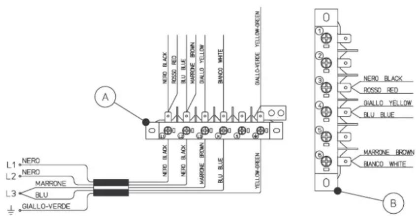
To change the connection from a star connection to a delta connection, modify the connections shown in the diagram (beside) on the power cord, the input terminal board (A), and the branching terminal board (B).
Dreiecksanschluss.
To change the connection from a star connection to a single-phase connection, modify the connections shown in the diagram (beside) on the power cord, the input terminal board (A), and the branching terminal board (B).
Einphasenanschluss
Single-Phase Connection with Three-Core Power Cord
To change the connection from a three-phase connection to a single-phase star connection, change the power cord and replace it with a three-core power cord of the HO7RN-F 3x4 mm2 type (SJO 3x10 AWG for machines used in the USA). Add the supplied two jumpers (C) to the input terminal board (A) and modify the connections on the input terminal board (A) and on the branching terminal board (B) as shown in the diagram (beside).
- GAGGIA®
- DICHIARAZIONE DI CONFORMITA' CE – DECLARATION DE CONFORMITE CE EG-KONFORMITÄTSERKLÄRUNG – EC DECLARATION OF CONFORMITY DECLARACIÓ DE CONFORMIDAD CE
- REGOLAZIONE DEL PRESSOSTATO
- TARATURA PRESSIONE POMPA
- Attenzione!
- NF08/009/B
- - INSTRUCTIONS BOOKLET CONSERVATION AND USE
- - ENVISAGED MACHINE USE
- - SAFETY ADVICE
- - INSTALLATION
- WATER CONNECTION
- ELECTRICAL CONNECTION
- GAS CONNECTION
- - START UP
- IMPORTANT
- LONG COFFEE GIGLEUR
- PRESSURE SWITCH ADJUSTMENT
- PUMP PRESSURE CALIBRATION
- Warning !!
- FILTERS FOR COFFEE MACHINE
- NF08/002/B
- NF08/004/B
- NF08/005/B
- REPLACEMENT OF THE THERMOSTAT TO REDUCE THE COFFEE DISPENSING GROUP TEMPERATURE (OPTIONAL).
- SPOUTS INCLUDED IN THE SUPPLY.
- - FUNCTION / USE AND PROGRAMMING
- INTRODUCTION
- COFFEE MEASURE PROGRAMMING
- TEA MEASURE PROGRAMMING (HOT WATER)
- COFFEE DELIVERY
- CONTINUOUS COFFEE MEASURES
- SPECIAL FUNCTIONS
- WASHING ALARM
- CAPPUCCINO MACHINE CLEANING
- PRE-INFUSION
- MIXED TEA (HOT WATER)
- ENGAGEMENT/DEACTIVATION
- TEA DELIVERY
- CAPPUCCINO AND MILK FUNCTION
- ENGAGEMENT/ DEACTIVATION
- CAPPUCCINO DELIVERY AND PROGRAMMING
- MILK PROGRAMMING AND DELIVERY
- FURTHER FUNCTIONS ON MACHINES EQUIPPED WITH DISPLAY
- LANGAUGE SELECTION
- CONSUMPTION READING
- ALARM CONDITION
- - PURIFIER REGENERATION
- HARDNESS °F 8 LITRE PURIFIER 12 LITRE PURIFIER
- - GAS ADJUSTMENT
- - MAINTENANCE AND USEFUL ADVICE
- Weekly cleaning operations
- Below-cup seal replacement
- - MACHINE DISMANTLING
- LEGENDA COMPONENTI - COMPONENTS LIST - LEGENDE BAUTEILE
- COLLEGAMENTO ELETTRICO - ELECTRICAL CONNECTION -
- RACCORDEMENT ELECTRIQUE - STROMANCHLUSS - CONEXIÓN ELÉCTRICA
- Standardanschluss
- Raccordement standard
- Conexión estándar
- Dreiecksanschluss.
- Einphasenanschluss
- Single-Phase Connection with Three-Core Power Cord
Brand : GAGGIA
Model : GE
Category : Coffee maker