
FMJ T31 - Tuner ARCAM - Free user manual and instructions
Find the device manual for free FMJ T31 ARCAM in PDF.


| Product Type | Tuner |
| Brand | Arcam |
| Model | FMJ T31 |
| Dimensions (W x D x H) | 430 x 290 x 85 mm |
| Net Weight | 3.8 kg |
| Power Consumption | 10 VA |
| FM Tuning Range | 87.5 – 108.0 MHz |
| FM Frequency Steps | 50 kHz |
| FM Sensitivity (IHF for 50dB S/N) | Typical 3 µV |
| FM Alternate Channel Selectivity | > 60 dB |
| FM Frequency Response | 20 Hz – 15 kHz ±1 dB |
| FM S/N Ratio (CCIR) | Mono > -75 dB, Stereo > -70 dB |
| FM THD (1 kHz, 96 MHz) | Mono < 0.1%, Stereo < 0.2% |
| FM Channel Separation (1 kHz) | > 40 dB |
| FM Output Level (75 kHz deviation) | 700 mV |
| AM Tuning Range (10 kHz step) | 530 – 1710 kHz |
| AM Tuning Range (9 kHz step) | 531 – 1602 kHz |
| AM Usable Sensitivity | Typical 30 µV |
| AM Output Level (70% modulation) | 300 mV |
| Presets | 30 FM (16 direct access), 16 AM |
| Audio Outputs | 2 pairs (RCA), 220 Ω impedance |
| Control Inputs | IR remote (RC5), 12V trigger |
| Supplied Accessories | FM dipole aerial, AM loop aerial, mains lead, CR-389 remote control, batteries |
| Safety Compliance | IEC 60065 |
| Cleaning | Unplug, wipe with soft damp lint-free cloth; do not use solvents |
Frequently Asked Questions - FMJ T31 ARCAM
User questions about FMJ T31 ARCAM
0 question about this device. Answer the ones you know or ask your own.
Ask a new question about this device
Download the instructions for your Tuner in PDF format for free! Find your manual FMJ T31 - ARCAM and take your electronic device back in hand. On this page are published all the documents necessary for the use of your device. FMJ T31 by ARCAM.
USER MANUAL FMJ T31 ARCAM
Arcam T3I AM/FM tuner
Tuner FM/PO Arcam T31
Arcam AM/FM-Tuner T3I
Safety guidelines

CAUTION
RISK OF ELECTRIC SHOCK DO NOT OPEN
ATTENTION
RISQUE DE CHOC ELECTRIQUE NE PAS OUVRIR

CAUTION: To reduce the risk of electric shock, do not remove cover (or back). No user serviceable parts inside. Refer servicing to qualified service personnel.
WARNING: To reduce the risk of fire or electric shock, do not expose this apparatus to rain or moisture.

The lightning flash with an arrowhead symbol within an equilateral triangle, is intended to alert the user to the presence of uninsulated 'dangerous voltage' within the product's enclosure that may be of sufficient magnitude to constitute a risk of electric shock to persons.

The exclamation point within an equilateral triangle is intended to alert the user to the presence of important operating and maintenance (servicing) instructions in the literature accompanying the product.
CAUTION: In Canada and the USA, to prevent electric shock, match the wide blade of the plug to the wide slot in the socket and insert the plug fully into the socket.
IMPORTANT SAFETY INSTRUCTIONS
This product is designed and manufactured to meet strict quality and safety standards. However, you should be aware of the following installation and operation precautions:
I. Take heed of warnings and instructions
You should read all the safety and operating instructions before operating this appliance. Retain this handbook for future reference and adhere to all warnings in the handbook or on the appliance.
2. Water and moisture
The presence of electricity near water can be dangerous. Do not use the appliance near water – for example next to a bathtub, washbowl, kitchen sink, in a wet basement or near a swimming pool, etc.
3. Object or liquid entry
Take care that objects do not fall and liquids are not spilled into the enclosure through any openings. Liquid filled objects such as vases should not be placed on the equipment.
4. Ventilation
Do not place the equipment on a bed, sofa, rug or similar soft surface, or in an enclosed bookcase or cabinet, since ventilation may be impeded. We recommend a minimum distance of 50mm (2 inches) around the sides and top of the appliance to provide adequate ventilation.
5. Heat
Locate the appliance away from naked flames or heat producing equipment such as radiators, stoves or other appliances (including other amplifiers) that produce heat.
6. Climate
The appliance has been designed for use in moderate climates.
7. Racks and stands
Only use a rack or stand that is recommended for use with audio equipment. If the equipment is on a portable rack it should be moved with great care, to avoid overturning the combination.
8. Cleaning
Unplug the unit from the mains supply before cleaning.
The case should normally only require a wipe with a soft, damp, lint-free cloth. Do not use paint thinners or other chemical solvents for cleaning.
We do not advise the use of furniture cleaning sprays or polishes as they can cause indelible white marks if the unit is subsequently wiped with a damp cloth.
9. Power sources
Only connect the appliance to a power supply of the type described in the operating instructions or as marked on the appliance.
10. Power-cord protection
Power supply cords should be routed so that they are not likely to be walked on or pinched by items placed upon or against them, paying particular attention to cords and plugs, and the point where they exit from the appliance.
II. Grounding
Ensure that the grounding means of the appliance is not defeated.
12. Power lines
Locate any outdoor antenna/aerial away from power lines.
13. Non-use periods
If the unit has a standby function, a small amount of current will continue to flow into the equipment in this mode. Unplug the power cord of the appliance from the outlet if left unused for a long period of time.
14. Abnormal smell
If an abnormal smell or smoke is detected from the appliance, turn the power off immediately and unplug the unit from the wall outlet. Contact your dealer immediately.
15. Servicing
You should not attempt to service the appliance beyond that described in this handbook. All other servicing should be referred to qualified service personnel.
16. Damage requiring service
The appliance should be serviced by qualified service personnel when:
A. the power-supply cord or the plug has been damaged, or
B. objects have fallen, or liquid has spilled into the appliance, or
C. the appliance has been exposed to rain, or
D. the appliance does not appear to operate normally or exhibits a marked change in performance, or
E. the appliance has been dropped or the enclosure damaged.
SAFETY COMPLIANCE
This product has been designed to meet the IEC 60065 international electrical safety standard.
Using this handbook
This handbook has been designed to give you all the information you need to install, connect, set up and use the Arcam T31 tuner. The CR-389 remote control handset supplied with this equipment is also described.
SAFETY
Safety guidelines are set out on the inside front cover of this handbook.
Many of these items are common sense precautions, but for your own safety, and to ensure that you do not damage the unit, we strongly recommend that you read them.
RADIO INTERFERENCE
All Arcam products have been designed to very high standards of electromagnetic compatibility.
However, both CD players and DVD players generate RF (radio frequency) energy. In some cases this can cause interference with FM and AM radio reception. If this is the case, switch the player off or keep the player and its connecting cables as far from the tuner and its aerials as possible. Connecting the player and the tuner/amplifier to different mains sockets can also help to reduce interference.
EU COUNTRIES
This product has been designed to comply with directive 89/336/EEC.
USA
This product complies with FCC requirements. If the equipment causes interference to radio/television reception, which can be determined by switching the equipment off and on, the following measures should be taken: Re-orientate the receiving antenna or route the antenna cable of the receiver as far as possible from this appliance and its cabling. Relocate the receiver with respect to this appliance. Connect the receiver and this appliance to different mains power outlets. If the problem persists contact your Arcam dealer or Arcam Customer Support on +44 (0) 1223 203203.
INFORMATION ON RADIO TRANSMISSIONS
A free booklet (number 004-000-00345-4) is available from the U.S. Government called 'How to Identify and Resolve Radio-TV Interference Problems' by writing to:
The U.S. Government Printing Office, Washington, D.C. 20402.
The British Broadcasting Corporation publishes a booklet entitled 'Radio Transmitting Stations' which contains details of all BBC transmitters in the UK together with other useful hints and tips. This booklet can be obtained on request by sending a large stamped addressed envelope to:
Engineers Dept.
BBC Radio
201 Wood Lane
LONDON W12 7TS
Telephone: 08700 100 123
Internet: www.bbc.co.uk/enginfo/fm_recep
CONTENTS
Safety guidelines....2
Important safety instructions....2
Safety compliance....2
Using this handbook....3
Safety 3
Information on radio transmissions....3
Contents....3
Installation 4
Positioning the unit 4
Setting up the tuner....4
Connecting to other equipment....5
Connecting your tuner to your amplifier....5
Connecting to a power supply 5
Custom installation features....5
Infrared (IR) remote commands....5
Using your tuner....6
Front panel controls....6
Operation 6
Storing a preset 7
Deleting an unused preset....7
RDS: Radio Data System....7
Entering station names manually....7
Using the CR-389 remote control 8
Technical specifications....9
Table of IR commands....10
Guarantee....II
On line registration....11
The UK Radio Authority publishes 'The Radio Authority Pocket Book' which contains details of all independent radio stations. This booklet can be obtained on request by sending a large stamped addressed envelope to:
Holbrook House
14 Great Queen Street
Holborn
LONDON
WC2B 5DG
Telephone: 0207 430 2724
Fax: 0207 405 7062
E-mail: info@radioauthority.org.uk
Internet: www.radioauthority.org.uk
Installation
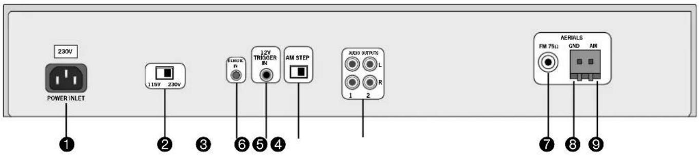
T3I REAR PANEL
① Socket for IEC power inlet line
② Voltage selector switch
③ Remote control input
4 Power On/Standby trigger in
⑤ AM step switch
6 Audio output phono sockets, two pairs
⑦ FM coaxial plug
8 Ground socket (for AM loop aerial)
⑨ AM socket (for AM loop aerial)
POSITIONING THE UNIT
Always place the tuner on a level, firm surface.
SETTING UP THE TUNER
AM STEP SWITCH ⑤
The AM tuning 'step size' needs to be set according to your location. This is done using the switch on the rear panel: set it to 10kHz if you are in North America, or 9kHz anywhere else. This switch also ensures correct reproduction of FM broadcasts for your location.
AM AERIAL
An AM aerial is required to receive AM/Medium Wave radio signals.
An external AM loop aerial is supplied as an accessory. This should be attached to the AM Antenna inputs with one end connected to AM
⑨ and the other to Ground ⑧. It does not matter which way round this aerial is fitted. Rotate the aerial to discover which position gives the best reception.
In areas of weak reception or when the receiver is used inside a steel framed building (such as an apartment building) you can use a wire between 3 and 5 metres long to strengthen reception. Mount this high up outside the building, if possible, and connect one end of this wire to the AM antenna input ⑨ as well as the loop aerial supplied. DO NOT DISCONNECT THE LOOP AERIAL.
FM AERIAL
An FM aerial is required to receive VHF radio signals. An external FM ribbon aerial is supplied as an accessory.
For optimal FM radio reception a roof or loft mounted aerial is advised. For your own safety it is recommended that a roof top aerial is fitted by an experienced contractor. Your Arcam dealer should be able to put you in contact with an aerial installer. A contractor will be able to tune your aerial to the nearest FM transmitter. In an apartment building an aerial system may already be installed. If this is the case you should have sockets in your home marked FM or VHF (do not use those marked TV).
The 'T' shaped wire aerial (dipole design) supplied should give reasonably good reception. Mount this aerial as high up as possible on a wall with the elements positioned horizontally. Try each usable wall of the room to see which gives best reception. Use tacks or adhesive tape to secure the aerial in a T-shape. The tacks should not come into contact with the internal wire of the aerial.
Whether you decide to get an aerial professionally installed or opt to use the supplied aerial it should be connected to the FM Antenna input ⑦ on the rear of the unit.
For use in North America, use an F-type antenna connector; for Europe and other areas, use a female Belling Lee-type coaxial connector.
CONNECTING TO OTHER EQUIPMENT
INTERCONNECT CABLES
Interconnecting cables are not supplied with this tuner. We recommend high quality cables as inferior quality cables will degrade the sound quality of your system. Please contact your Arcam dealer for details of suitable cables. Arcam do not recommend any particular type or brand of interconnect cable.
CONNECTING YOUR TUNER TO YOUR AMPLIFIER
AUDIO OUTPUTS ⑥
Two pairs of identical outputs are provided.
Connect one set to your amplifier's tuner input or any other line-level input using suitable high quality interconnect cables. Ensure that the left and right audio outputs from the tuner are connected to the same left and right inputs on your amplifier.
The second set of audio outputs can be used to connect to a second amplifier set up for 'multiroom' use, or routed to a tape recorder for 'off air' recording.
CONNECTING TO A POWER SUPPLY
WRONG PLUG?
Check that the plug supplied with the unit fits your supply and that your mains supply voltage agrees with the voltage setting switch (115V or 230V) indicated on the rear panel of the unit ②.
If your mains supply voltage is different, switch the voltage selector across using a small screwdriver.
MAINS LEAD
The appliance is normally supplied with a moulded mains plug already fitted to the lead. If for any reason the plug needs to be removed, it must be disposed of immediately and securely, as it is a potential shock hazard when inserted into the mains socket. Should you require a new mains lead, contact your Arcam dealer.
PLUGGING IN
Push the plug (IEC line socket) of the power cable supplied with the unit into the POWER INLET socket ① in the back of the unit. Make sure it is pushed in firmly.
Put the plug on the other end of the cable into your power supply socket and switch the socket on.
CUSTOM INSTALLATION FEATURES
The T3I has a number of useful features that make it ideal for a custom installation, where the tuner is fully integrated with a specialist control system or operated by a programmable remote control.
REMOTE CONTROL INPUT ③
A rear panel input that receives modulated carrier-based infrared (IR) commands in RC5 format. The input is suitable for connection to a simple IR eye or to an external controller.
Use of this socket disables the front panel IR eye.
TRIGGER INPUT ④
The trigger socket allows the tuner to be remotely switched in and out of standby. The primary front panel POWER switch must be in, 'on', for this mode.
Apply a +12V DC voltage for 'on', the power indicator glows green; 0V for 'standby', the power indicator glows red.
Note that use of this socket requires a 12V signal before the tuner can be switched fully on.
INFRARED (IR) REMOTE COMMANDS
The T31 responds to a set of Philips RC-5 codes in addition to those available on the supplied handset, which is kept simple for ease of use.
Advanced programmable control devices, such as the Philips 'Pronto' and other system controllers, can be set up to use the additional codes. Refer to the instructions for your programmable device for details.
A table of IR commands is provided on page 10 of this Handbook.
Using your tuner
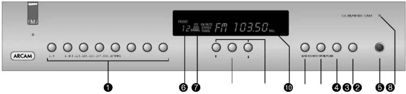
FRONT PANEL CONTROLS
Preset Memory buttons ①
Directly select up to 32 preset stations (16 AM, 16 FM). Press briefly for stations 1–8, press and hold for more than one second for stations 9–16.
BAND ②
Selects FM or AM frequency band. The appropriate letters appear on the display.
RDS ③
Switches between RDS modes on FM if RDS is available. See the section 'RDS: Radio Data System'.
MONO 4
Selects mono or stereo output. Stereo is only available on FM radio stations. If a weak station is received in stereo the background hiss can be reduced (and in most cases eliminated) by selecting 'MONO'.
In mono mode, FM muting is suppressed when tuning between stations and the 'FM MUTE' indicator is switched off.
STORE 5
The STORE button allows you to assign radio stations to preset numbers. See the instruction 'Storing a preset'
Preset indicator 6
Indicates the number of the preset currently selected.
Signal strength ⑦
A seven-step indicator shows the strength of a tuned station. Good FM reception and locking onto RDS data generally requires five or more bars.
Tuning 8
Switches between Tune and Preset mode for the down/up buttons. Preset mode is indicated by PRESET on the display.
Tune down/up ⑨
Used to either scroll through presets, or to tune up and down the broadcast band, depending on the current mode. See 'Tuning to a station' for more details.
Frequency/ RDS display 10
Indicates the frequency of the selected station in MHz (FM) or kHz (AM); it also displays RDS information when present.
POWER 11
Switches the mains power to the unit on or off.
Power indicator 12
This glows green to show that the unit is ready for use. The indicator glows red in standby mode when the tuner is switched off via the remote control, or configured in a custom installation.
OPERATION
The T31 radio tuner can be controlled from the front panel buttons or from the remote control handset (see 'Using the remote control').
TUNING TO A STATION
Pressing the TUNING button toggles between the two tuning modes of the unit – 'Preset' or 'Tune'. The selected mode is briefly shown in the display.
PRESET MODE
In Preset mode, press the ▲ or ▼ buttons on the front panel (or < or > on the remote control handset) to cycle up and down the preset stations.
See 'Storing a preset' and 'Deleting unused presets', below.
TUNE MODE
Automatic tuning:
Press the ▲ or ▼ buttons on the front panel (or < or > on the remote control handset) for longer than one second to engage automatic tuning. The tuner searches for a radio station signal of sufficient strength and stops. To skip to the next station, press one of the buttons again. Automatic tuning is available for both the FM and AM bands.
Manual tuning:
Tap the ▲ or ▼ buttons for manual tuning. This can be used for tuning to a specific frequency. It is also useful if you are trying to select a station that is too weak for the auto search mode.
Regardless of the mode used to tune your T31, when it is accurately tuned to a station 'TUNED' lights up in the display.
STORING A PRESET
To store a preset, tune to the radio station you wish to store. Press the STORE button: this causes 'PRESET STORE' to flash in the display. Now select the preset number you wish to assign to the station using the preset memory buttons or the ▲ and ▼ buttons on the front panel. Press the STORE button again.
Once the preset is stored, the display reverts to show the station name (if RDS information is transmitted) or its frequency.
To quit the memory function without storing a preset, leave the tuner controls untouched for ten seconds. It is also possible to overwrite a stored station by saving another in its place. There are thirty presets available for FM use and sixteen for AM use.
Your presets are retained when the T31 is disconnected from the mains supply.
DELETING AN UNUSED PRESET
Press the RDS and STORE buttons on the front panel, wait about three seconds, then select the preset number you want to delete using the ▲ and ▼ buttons, followed by the RDS button.
The display briefly shows 'DELETED' and '-' is shown in place of the preset number. You can reactivate a deleted preset number by storing a station in the normal way.
RDS: RADIO DATA SYSTEM
The Arcam T31 supports RDS Programme Service and RDS Radio Text on FM broadcasts.
When a station carrying RDS information is selected 'RDS' lights up in the display and shortly afterwards the station's RDS name (e.g. 'BBC R3') is shown.
Press the RDS button to view any RDS text information (if a station is not transmitting text information, the display briefly indicates 'NO TEXT' and reverts to show the station name).
Press RDS again to display the station's frequency.
Pressing RDS a third time returns you to a display of the station name.
If the RDS button is pressed while tuned to a non-RDS station, the display shows 'NO NAME' for three seconds before reverting to the default display.
ENTERING STATION NAMES MANUALLY
Station names can be entered and saved for preset AM stations, and for FM stations where RDS is not available. Station names can be up to eight characters long.
First select the band and the preset station you wish to name. Then press and hold the RDS button for more than two seconds. An 'underscore' line should appear blinking in the first position of the frequency display area. Use the ▲ and ▼ buttons beneath the display to scroll through the available alphabet, numbers and special characters available until you reach your wanted letter or character. Press the TUNING button to confirm that character. The 'underscore' line will then move to the next position. Repeat this process to enter the required name. If you want to edit a character later, use the
TUNING button to step along and select it, then use the ▲ and ▼ keys as before to change it. When complete, press STORE to enter the name into the preset memory.
Using the CR-389 remote control
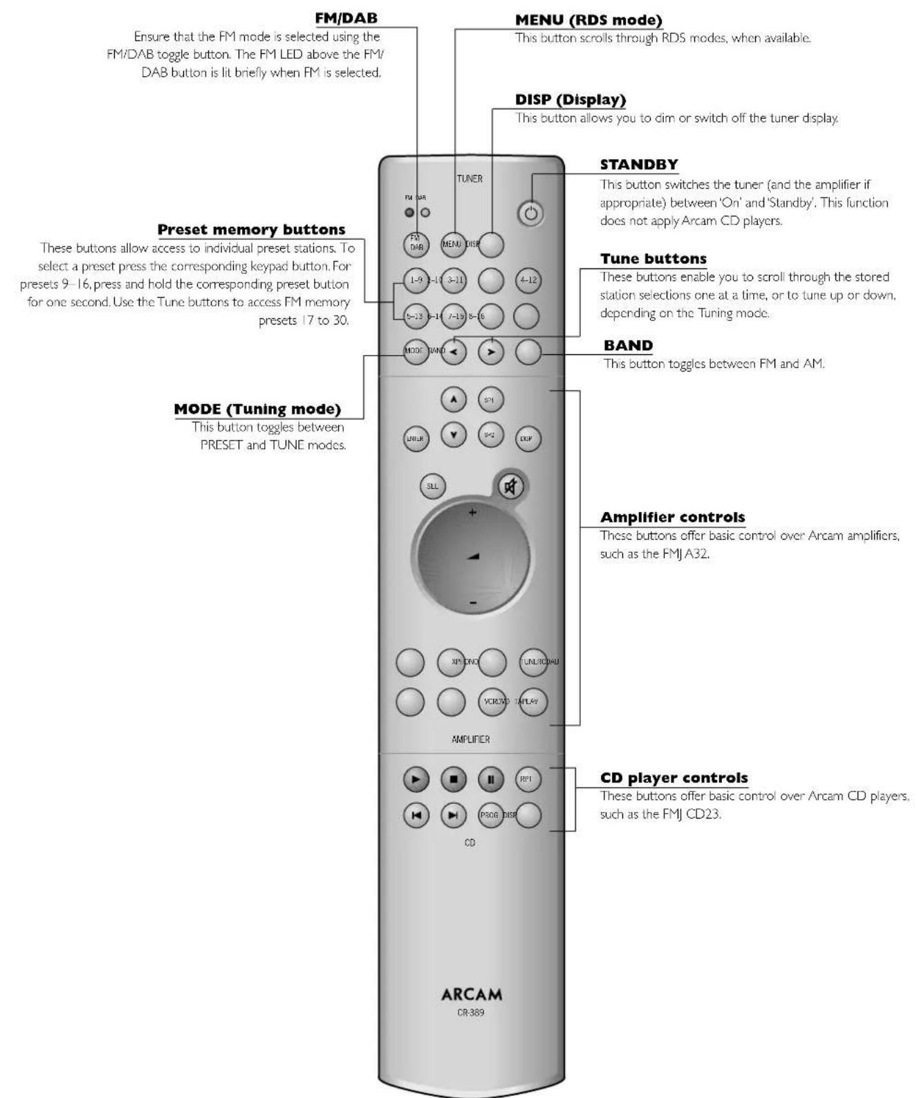
NOTE: DAB (Digital Audio Broadcast) refers to Arcam DAB tuners such as model DT81.
NOTE: Remember to install the two AAA batteries supplied before trying to use your remote control.
Do not place anything in front of the display area on the tuner (where the IR receiver is located), or the remote control may not work.
Technical specifications
T31 TUNER
FM Section
Tuning range 87.5 to 108.0MHz
Frequency steps 50kHz
Presets: total/direct access 30/16
Sensitivity (IHF) for 50dB S/N ratio typically 3μV
Alternate channel selectivity better than 60dB
Capture ratio 1.5dB
Frequency response 20Hz–15kHz ±1dB
Ultimate S/N ratio (CCIR) Mono better than -75dB
Stereo better than -70dB
Total harmonic distortion (96MHz reference, 22.5kHz deviation at 1kHz)
Mono better than 0.1%
Stereo better than 0.2%
Channel separation (1kHz) better than 40dB
Pilot tone suppression better than 60dB
Output level 700mV at 75kHz deviation
AM Section
Tuning range: 10kHz step; 530 to 1710 kHz
9kHz step; 531 to 1602 kHz
Presets 16
Usable sensitivity typically 30μV
IF rejection > 36dB
S/N ratio (30% mod., 50mV I/P) > 38dB
Total harmonic distortion (30% mod., 50mV I/P) < 3%
Output level 300mV at 70% modulation
Control inputs
IR remote standard Philips RC-5, 36kHz carrier
IR in signal level 4–15V pk-pk
Trigger operating voltage 9–15V DC
Trigger in polarity tip positive
General
Output impedance 220Ω
Minimum recommended load 5kΩ
Power consumption 10VA
Size W × D × H 430 × 290 × 85mm
Weight net 3.8kg
Weight packed 6.0kg
Supplied accessories FM dipole aerial
AM loop aerial
mains lead
CR-389 remote control handset and batteries
E&OE
CONTINUAL IMPROVEMENT POLICY
Arcam has a policy of continual improvement for its products. This means that designs and specifications are subject to change without notice.
NOTE: All specification values are typical unless otherwise stated.
TABLE OF IR COMMANDS
Command Decimal code
| Standby 17-124 | |
| On 17-123 | |
| Power toggle 17-12 | |
| AM/FM band toggle 17-50 | |
| AM band 17-52, 17-46 | |
| FM band 17-53, 17-45 | |
| Tune down (seek if >1second) 17-31 | |
| Tune up (seek if >1second) 17-30 | |
| Seek tune down 17-35 | |
| Seek tune up 17-34 | |
| RDS program 17-62 | |
| RDS text | 17-63 |
| RDS frequency | 17-64 |
| Scroll RDS mode | 17-55, 17-61, 17-15 |
| Display on | 17-14 |
| Display toggle 17-18 | |
| Stereo | 17-39 |
| Mono | 17-54 |
| Stereo/Mono toggle | 17-38 |
| Preset/tune mode toggle | 17-37 |
| Preset/tune up | 17-32 |
| Preset/tune down | 17-33 |
| Store | 17-41 |
| Mute on | 17-119 |
| Mute off | 17-120 |
| Mute toggle | 17-13 |
| Preset 1 to 8 (9 to 16 if >1second) | 17-1 to 17-8 |
| Preset 9 | 17-9 |
| Preset 10 to 17 | 17-110 to 17-117 |
| Preset 18 to 30 | 17-88 to 17-100 |
NOTE: The above codes are consistent with the Philips RC-5 standard.
Guarantee
WORLDWIDE GUARANTEE
This entitles you to have the unit repaired free of charge, during the first two years after purchase, at any authorised Arcam distributor provided that it was originally purchased from an authorised Arcam dealer or distributor. The manufacturer can take no responsibility for defects arising from accident, misuse, abuse, wear and tear, neglect or through unauthorised adjustment and/or repair, neither can they accept responsibility for damage or loss occurring during transit to or from the person claiming under the guarantee.
The warranty covers:
Parts and labour costs for two years from the purchase date. After two years you must pay for both parts and labour costs. The warranty does not cover transportation costs at any time.
CLAIMS UNDER GUARANTEE
This equipment should be packed in the original packing and returned to the dealer from whom it was purchased, or failing this, directly to the Arcam distributor in the country of residence. It should be sent carriage prepaid by a reputable carrier — NOT by post. No responsibility can be accepted for the unit whilst in transit to the dealer or distributor and customers are therefore advised to insure the unit against loss or damage whilst in transit.
For further details contact Arcam at:
Arcam Customer Support Department,
Pembroke Avenue, Waterbeach, CAMBRIDGE, CB5 9PB, England
Telephone: +44 (0)1223 203203
Fax: +44 (0)1223 863384
Email: support@arcam.co.uk
QUESTIONS?
Always contact your dealer in the first instance.
If your dealer is unable to answer any query regarding this or any other Arcam product please contact your local distributor. A list of current distributors can be found at www.arcam.co.uk. In the U.K., contact Arcam Customer Support on 01223 203203 or write to us at the above address and we will do our best to help you.
You can register your Arcam product on line at:
www.arcam.co.uk/reg
- Safety guidelines
- CAUTION
- ATTENTION
- IMPORTANT SAFETY INSTRUCTIONS
- Take heed of warnings and instructions
- Water and moisture
- Object or liquid entry
- Ventilation
- Heat
- Climate
- Racks and stands
- Cleaning
- Power sources
- Power-cord protection
- Grounding
- Power lines
- Non-use periods
- Abnormal smell
- Servicing
- Damage requiring service
- SAFETY COMPLIANCE
- Using this handbook
- SAFETY
- RADIO INTERFERENCE
- EU COUNTRIES
- USA
- INFORMATION ON RADIO TRANSMISSIONS
- CONTENTS
- Installation
- T3I REAR PANEL
- POSITIONING THE UNIT
- SETTING UP THE TUNER
- AM STEP SWITCH ⑤
- AM AERIAL
- FM AERIAL
- CONNECTING TO OTHER EQUIPMENT
- INTERCONNECT CABLES
- CONNECTING YOUR TUNER TO YOUR AMPLIFIER
- AUDIO OUTPUTS ⑥
- CONNECTING TO A POWER SUPPLY
- WRONG PLUG?
- MAINS LEAD
- PLUGGING IN
- CUSTOM INSTALLATION FEATURES
- REMOTE CONTROL INPUT ③
- TRIGGER INPUT ④
- INFRARED (IR) REMOTE COMMANDS
- Using your tuner
- FRONT PANEL CONTROLS
- Preset Memory buttons ①
- BAND ②
- RDS ③
- MONO 4
- STORE 5
- Preset indicator 6
- Signal strength ⑦
- Tuning 8
- Tune down/up ⑨
- Frequency/ RDS display 10
- POWER 11
- Power indicator 12
- OPERATION
- TUNING TO A STATION
- PRESET MODE
- TUNE MODE
- Automatic tuning:
- Manual tuning:
- STORING A PRESET
- DELETING AN UNUSED PRESET
- RDS: RADIO DATA SYSTEM
- ENTERING STATION NAMES MANUALLY
- Using the CR-389 remote control
- Technical specifications
- T31 TUNER
- CONTINUAL IMPROVEMENT POLICY
- Guarantee
- WORLDWIDE GUARANTEE
- The warranty covers:
- CLAIMS UNDER GUARANTEE
- QUESTIONS?
Brand : ARCAM
Model : FMJ T31
Category : Tuner