
ThinkPad A20 - Laptop IBM - Free user manual and instructions
Find the device manual for free ThinkPad A20 IBM in PDF.


| Product Type | Laptop |
| Brand | IBM |
| Model | ThinkPad A20 (A20m, A20p) |
| Processor | Intel Celeron 500/550 MHz or Mobile Pentium III 500 MHz - 1 GHz with SpeedStep technology |
| Memory (RAM) | 64 MB or 128 MB standard, expandable up to 512 MB (2 SO-DIMM slots) |
| Hard Disk Drive | 2.5-inch IDE, capacities: 6.0, 12.0, 18.0, or 20.0 GB |
| Display | 12.1-inch SVGA (800x600), 14.1-inch XGA (1024x768), or 15.0-inch XGA/SXGA+/UXGA TFT color LCD |
| Graphics | Integrated video memory: 4 MB, 8 MB, or 16 MB (depending on model) |
| Diskette Drive | 3.5-inch 1.44 MB |
| Optical Drive | Ultrabay 2000: CD-ROM (10x-24x) or DVD-ROM (6x or 8x) |
| Modem | Internal 56.6 Kbps |
| Network | Optional Mini PCI Ethernet card (10/100) |
| Ports | External monitor, line-in, headphone, microphone, mouse/keyboard, parallel, serial, USB, RJ11, RJ45, TV-in/out (on select models), Infrared (IrDA 1.1) |
| PC Card Slots | One Type-III or two Type-II |
| Audio | Internal microphone, internal speaker, software volume control |
| Battery | 6-cell Li-Ion, rechargeable |
| AC Adapter | 72-watt, 2-pin or 3-pin depending on region |
| Dimensions (approx.) | 330 mm x 272 mm x 36 mm (13.0" x 10.7" x 1.4") |
| Weight (approx.) | 3.2 kg (7.1 lb) with battery |
| Operating System | Pre-installed: Windows 98, Windows 2000, or Windows NT (recovery CDs available) |
| Power Management | Screen blank, standby, and hibernation modes |
| Security | Power-on password, hard disk password, supervisor password (BIOS) |
| Serviceability | FRU (Field Replaceable Unit) design with detailed removal procedures; user-replaceable battery, keyboard, hard drive, memory, Mini PCI card, Ultrabay 2000 devices |
| Notices | Laser compliance (Class 1 for optical drives); safety notices for battery, LCD, and electrical handling |
Frequently Asked Questions - ThinkPad A20 IBM
User questions about ThinkPad A20 IBM
0 question about this device. Answer the ones you know or ask your own.
Ask a new question about this device
Download the instructions for your Laptop in PDF format for free! Find your manual ThinkPad A20 - IBM and take your electronic device back in hand. On this page are published all the documents necessary for the use of your device. ThinkPad A20 by IBM.
USER MANUAL ThinkPad A20 IBM
This manual supports:
ThinkPad A20m, A21m, A22m
(MT 2628/2633)
A20p, A21p, A22p
(MT 2629)
ThinkPad Dock (MT 2631)
Note
Before using this information and the product it supports, be sure to read the general information under "Notices" on page 150.
Second Edition (October 2001)
The following paragraph does not apply to the United Kingdom or any country where such provisions are inconsistent with local law:
INTERNATIONAL BUSINESS MACHINES CORPORATION PROVIDES THIS PUBLICATION "AS IS" WITHOUT ANY WARRANTY OF ANY KIND, EITHER EXPRESS OR IMPLIED, INCLUDING, BUT NOT LIMITED TO, THE LIMITED WARRANTIES OF MERCHANTABILITY OR FITNESS FOR A PARTICULAR PURPOSE. Some states do not allow disclaimer or express or implied warranties in certain transactions; therefore, this statement may not apply to you.
This publication could include technical inaccuracies or typographical errors. Changes are periodically made to the information herein; these changes will be incorporated in new editions of the publication. IBM may make improvements or changes to the products or the programs described in this publication at any time.
It is possible that this publication may contain references to, or information about, IBM products (machines and programs), programming, or services that are not announced in your country. Such references or information must not be construed to mean that IBM intends to announce such IBM products, programming, or services in your country.
Requests for technical information about IBM products should be made to your IBM authorized dealer or your IBM marketing representative.
© Copyright International Business Machines Corporation 2001. All rights reserved.
US Government Users Restricted Rights – Use, duplication or disclosure restricted by GSA ADP Schedule Contract with IBM Corp.
About this manual
This manual contains service and reference information for IBM ThinkPad A20, A21, A22 (MT2628, 2629, 2633), and ThinkPad Dock (MT2631) products. Use this manual along with the advanced diagnostic tests to troubleshoot problems.
The manual is divided into sections as follows:
- The common sections provide general information, guidelines, and safety information required in servicing computers.
•The product-specific section includes service, reference, and product-specific parts information.
Important
This manual is intended for trained service personnel who are familiar with ThinkPad products. Use this manual along with the advanced diagnostic tests to troubleshoot problems effectively.
Before servicing an IBM ThinkPad product, be sure to review the safety information under “Safety notices: multilingual translations” on page 3, “Safety Information” on page 14, and “Laser compliance statement” on page 18.
Contents
About this manual. . . . . . . . . . . . i i i
Introduction. 1
Important service information . . . . . . . . . 1
Strategy for replacing FRUs . . . . . . . . 1
How to use error messages . . . . . . . . 2
Diskette compatibility matrix . . . . . . . . . 2
Safety notices: multilingual translations . . . . . . 3
Safety information. 1 4
General safety. 1 4
Electrical safety . . . . . . . . . . . 1 5
Safety inspection guide . . . . . . . . . 1 6
Handling electrostatic discharge-sensitive devices 17
Grounding requirements . . . . . . . . . 1 8
Laser compliance statement. 18
General descriptions. 2 3
Read this first. 2 3
What to do first. 2 3
Related service information . . . . . . . . . 2 5
Power management. 30
Checkout guide . . . . . . . . . . . . 3 3
Testing the computer . . . . . . . . . . 3 3
Detecting system information with PC-Doctor. . . 35
Power system checkout . . . . . . . . . 3 5
ThinkPad A20m/p, A21m/p and A22m/p. . . . . 3 9
Product overview. 4 1
Specifications . . . . . . . . . . . . 4 1
Status indicators. 4 4
FRU tests . . . . . . . . . . . . . 4 6
Fn key combinations . . . . . . . . . . 4 8
Symptom-to-FRU index . . . . . . . . . . 4 9
Numeric error codes . . . . . . . . . . 4 9
Error messages 5 2
Beep symptoms . . . . . . . . . . . . 5 3
No beep symptoms . . . . . . . . . . . 5 3
LCD-related symptoms . . . . . . . . . 5 4
Intermittent problems . . . . . . . . . . 5 5
Undetermined problems . . . . . . . . . 5 5
FRU replacement notices . . . . . . . . . 5 6
Screw notices . . . . . . . . . . . . 5 6
Retaining serial numbers. 57
Removing and replacing a FRU. 5 9
1010 Battery pack. 6 0
1020 DIMM 6 1
1030 Mini PCI adapter . . . . . . . . . . 6 3
1040 Backup battery . . . . . . . . . . 6 6
1050 Hard-disk drive or RF ID adapter . . . . 6 7
1060 Ultrabay 2000 device . . . . . . . . 6 9
1070 Keyboard . . . . . . . . . . . 7 1
1080 Keyboard CRU insulator . . . . . . . 7 4
1090 Hinge cover and clear sheet icon . . . . 7 5
1100 Keyboard bezel and speaker. . . . . . 7 6
1110 Microphone and speaker cable . . . . . 7 8
1120 Sub card. 8 0
1130 PC Card slot assembly . . . . . . . 8 2
1140 Fan assembly. 8 3
1150 Diskette drive . . . . . . . . . 8 5
1160 Upper shield. 8 7
1170 TV card . . . . . . . . . . . . 8 8
1180 CPU socket and CPU . . . . . . . 8 9
1190 System board and RJ45/11 connector assembly. 9 1
Thermal rubbers location. 9 3
2010 LCD assembly . . . . . . . . . . 9 4
2020 Front bezel . . . . . . . . . . . 9 6
2030 Inverter card 9 9
2040 LCD panel . . . . . . . . . . 1 0 1
3010 ThinkPad Dock PCI cover . . . . . 1 0 5
3020 ThinkPad Dock top cover . . . . . 1 0 7
Locations . . . . . . . . . . . . . . 11 2
Front view. 11 2
Rear view. 11 3
Bottom view 11 4
Parts list 11 5
A series model matrix . . . . . . . . . 115
Overall 1 2 3
AC adapter 1 3 6
LCD FRUs. 1 3 6
Keyboard. 1 4 0
Recovery CDs 1 4 1
Miscellaneous parts. 1 4 5
Optional FRUs 1 4 7
Common parts list . . . . . . . . . 1 4 8
Notices . . . . . . . . . . . . . . 1 5 0
Trademarks 1 5 0
Introduction
Important service information
Important
BIOS and device driver fixes are customer-installable. The BIOS and device drivers are posted on the IBM support site http://www.ibm.com/pc/support
Advise customers to contact the PC Company HelpCenter at 800-772-2227 if they need assistance in obtaining or installing any diskette fixes.
Customers in Canada should call IBM HelpPC at 800-565-3344 for assistance or download information.
Strategy for replacing FRUs
Before replacing parts
Make sure that all diskette fixes are installed before replacing any FRUs listed in this manual.
Use the following strategy to prevent unnecessary FRU replacement and service expense:
- If you are instructed to replace a FRU but the replacement does not correct the problem, reinstall the original FRU before you continue.
- Some computers have both a processor board and a system board. If you are instructed to replace either the processor board or the system board, and replacing one of them does not correct the problem, reinstall that board, and then replace the other one.
- If an adapter or device consists of more than one FRU, any of the FRUs may be the cause of the error. Before replacing the adapter or device, remove the FRUs, one by one, to see if the symptoms change. Replace only the FRU that changed the symptoms.
Attention: The setup configuration on the computer you are servicing may have been customized. Running Automatic Configuration may alter the settings. Note the current configuration settings (using the View Configuration option); then, when service has been completed, verify that those settings remain in effect.
Strategy for replacing a hard-disk drive
Always try to run a low-level format before replacing a hard-disk drive.
Attention: The drive startup sequence in the computer you are servicing may have been changed. Be extremely careful during write operations such as copying, saving, or formatting. If you select an incorrect drive, data or programs can be overwritten.
How to use error messages
Use the error codes displayed on the screen to diagnose failures. If more than one error code is displayed, begin the diagnosis with the first error code. Whatever causes the first error code may also cause false error codes. If no error code is displayed, see if the error symptom is listed in the Symptom-to-FRU Index for the computer you are servicing.
Diskette compatibility matrix
The compatibility of each of the drives with the diskettes for it is as follows:
| Diskette drive | Diskette capacity | Compatibility |
| 3.5-inch 1.0 MB Read and write | ||
| 2.0 MB Read and write | ||
| 4.0 MB Not compatible | ||
Safety notices: multilingual translations
In this manual, safety notices appear in English with a page number reference to the appropriate multi-lingual, translated safety notice found in this section.
The following safety notices are provided in English, French, German, Italian, and Spanish languages.
Safety notice 1
Before the computer is powered-on after FRU replacement, make sure all screws, springs, and other small parts are in place and are not left loose inside the computer. Verify this by shaking the computer and listening for rattling sounds. Metallic parts or metal flakes can cause electrical shorts.
Some standby batteries contain a small amount of nickel and cadmium. Do not disassemble a standby battery, recharge it, throw it into fire or water, or short-circuit it. Dispose of the battery as required by local ordinances or regulations. Use only the battery in the appropriate parts listing. Use of an incorrect battery can result in ignition or explosion of the battery.
(continuation of safety notice 2)
The battery pack contains small amounts of nickel. Do not disassemble it, throw it into fire or water, or short-circuit it. Dispose of the battery pack as required by local ordinances or regulations. Use only the battery in the appropriate parts listing when replacing the battery pack. Use of an incorrect battery can result in ignition or explosion of the battery.
(continuation of safety notice 3)
The lithium battery can cause a fire, an explosion, or a severe burn. Do not recharge it, remove its polarized connector, disassemble it, heat it above 100^ C ( 212^ F), incinerate it, or expose its cell contents to water. Dispose of the battery as required by local ordinances or regulations. Use only the battery in the appropriate parts listing. Use of an incorrect battery can result in ignition or explosion of the battery.
(continuation of safety notice 4)
If the LCD breaks and the fluid from inside the LCD gets into your eyes or on your hands, immediately wash the affected areas with water for at least 15 minutes. Seek medical care if any symptoms from the fluid are present after washing.
To avoid shock, do not remove the plastic cover that protects the lower part of the inverter card.
Though the main batteries have low voltage, a shorted or grounded battery can produce enough current to burn personnel or combustible materials.
Before removing any FRU, power off the computer, unplug all power cords from electrical outlets, remove the battery pack, and then disconnect any interconnecting cables.
The following section contains the safety information that you need to be familiar with before servicing an IBM mobile computer.
General safety
Follow these rules to ensure general safety:
- Observe good housekeeping in the area of the machines during and after maintenance.
- When lifting any heavy object:
- Ensure you can stand safely without slipping.
- Distribute the weight of the object equally between your feet.
-
Use a slow lifting force. Never move suddenly or twist when you attempt to lift.
-
Lift by standing or by pushing up with your leg muscles; this action removes the strain from the muscles in your back. Do not attempt to lift any objects that weigh more than 16 kg (35 lb) or objects that you think are too heavy for you.
- Do not perform any action that causes hazards to the customer, or that makes the equipment unsafe.
- Before you start the machine, ensure that other service representatives and the customer's personnel are not in a hazardous position.
- Place removed covers and other parts in a safe place, away from all personnel, while you are servicing the machine.
- Keep your toolcase away from walk areas so that other people will not trip over it.
- Do not wear loose clothing that can be trapped in the moving parts of a machine. Make sure that your sleeves are fastened or rolled up above your elbows. If your hair is long, fasten it.
- Insert the ends of your necktie or scarf inside clothing or fasten it with a nonconductive clip, approximately 8 centimeters (3 inches) from the end.
- Do not wear jewelry, chains, metal-frame eyeglasses, or metal fasteners for your clothing.
Attention: Metal objects are good electrical conductors.
- Wear safety glasses when you are hammering, drilling, soldering, cutting wire, attaching springs, using solvents, or working in any other conditions that might be hazardous to your eyes.
• After service, reinstall all safety shields, guards, labels, and ground wires. Replace any safety device that is worn or defective.
- Reinstall all covers correctly before returning the machine to the customer.
Electrical safety
Observe the following rules when working on electrical equipment.
Important
Use only approved tools and test equipment. Some hand tools have handles covered with a soft material that does not insulate you when working with live electrical currents.
Many customers have, near their equipment, rubber floor mats that contain small conductive fibers to decrease electrostatic discharges. Do not use this type of mat to protect yourself from electrical shock.
- Find the room emergency power-off (EPO) switch, disconnecting switch, or electrical outlet. If an electrical accident occurs, you can then operate the switch or unplug the power cord quickly.
- Do not work alone under hazardous conditions or near equipment that has hazardous voltages.
- Disconnect all power before:
– Performing a mechanical inspection
– Working near power supplies
– Removing or installing main units
- Before you start to work on the machine, unplug the power cord. If you cannot unplug it, ask the customer to power-off the wall box that supplies power to the machine and to lock the wall box in the off position.
- If you need to work on a machine that has exposed electrical circuits, observe the following precautions:
- Ensure that another person, familiar with the power-off controls, is near you.
Attention: Another person must be there to switch off the power, if necessary.
- Use only one hand when working with powered-on electrical equipment; keep the other hand in your pocket or behind your back.
Attention: An electrical shock can occur only when there is a complete circuit. By observing the above rule, you may prevent a current from passing through your body.
- When using testers, set the controls correctly and use the approved probe leads and accessories for that tester.
- Stand on suitable rubber mats (obtained locally, if necessary) to insulate you from grounds such as metal floor strips and machine frames.
Observe the special safety precautions when you work with very high voltages; these instructions are in the safety sections of maintenance information. Use extreme care when measuring high voltages.
- Regularly inspect and maintain your electrical hand tools for safe operational condition.
- Do not use worn or broken tools and testers.
- Never assume that power has been disconnected from a circuit. First, check that it has been powered off.
•Always look carefully for possible hazards in your work area. Examples of these hazards are moist floors, nongrounded power extension cables, power surges, and missing safety grounds.
- Do not touch live electrical circuits with the reflective surface of a plastic dental mirror. The surface is conductive; such touching can cause personal injury and machine damage.
- Do not service the following parts with the power on when they are removed from their normal operating places in a machine:
– Power supply units
- Pumps
- Blowers and fans
- Motor generators
and similar units. (This practice ensures correct grounding of the units.)
- If an electrical accident occurs:
– Use caution; do not become a victim yourself.
- Switch off power.
– Send another person to get medical aid.
Safety inspection guide
The purpose of this inspection guide is to assist you in identifying potentially unsafe conditions. As each machine was designed and built, required safety items were installed to protect users and service personnel from injury. This guide addresses only those items. You should use good judgment to identify potential safety hazards due to attachment of non-IBM features or options not covered by this inspection guide.
If any unsafe conditions are present, you must determine how serious the apparent hazard could be and whether you can continue without first correcting the problem.
Consider these conditions and the safety hazards they present:
- Electrical hazards, especially primary power (primary voltage on the frame can cause serious or fatal electrical shock)
- Explosive hazards, such as a damaged CRT face or a bulging capacitor
- Mechanical hazards, such as loose or missing hardware
To determine whether there are any potentially unsafe conditions, use the following checklist at the beginning of every service task. Begin the checks with the power off, and the power cord disconnected.
Checklist:
-
Check exterior covers for damage (loose, broken, or sharp edges.)
-
Power-off the computer. Disconnect the power cord.
-
Check the power cord for:
a. A third-wire ground connector in good condition.
Use a meter to measure third-wire ground continuity for 0.1 ohm or less between the external ground pin and frame ground.
b. The power cord should be the type specified in the parts list.
c. Insulation must not be frayed or worn.
-
Remove the cover.
-
Check for any obvious non-IBM alterations. Use good judgment as to the safety of any non-IBM alterations.
- Check inside the unit for any obvious unsafe conditions, such as metal filings, contamination, water or other liquids, or signs of fire or smoke damage.
- Check for worn, frayed, or pinched cables.
- Check that the power-supply cover fasteners (screws or rivets) have not been removed or tampered with.
Handling electrostatic discharge-sensitive devices
Any computer part containing transistors or integrated circuits (ICs) should be considered sensitive to electrostatic discharge (ESD.) ESD damage can occur when there is a difference in charge between objects. Protect against ESD damage by equalizing the charge so that the machine, the part, the work mat, and the person handling the part are all at the same charge.
Notes
- Use product-specific ESD procedures when they exceed the requirements noted here.
- Make sure that the ESD protective devices you use have been certified (ISO 9000) as fully effective.
When handling ESD-sensitive parts:
- Keep the parts in protective packages until they are inserted into the product.
-
Avoid contact with other people.
-
Wear a grounded wrist strap against your skin to eliminate static on your body.
- Prevent the part from touching your clothing. Most clothing is insulative and retains a charge even when you are wearing a wrist strap.
- Use the black side of a grounded work mat to provide a static-free work surface. The mat is especially useful when handling ESD-sensitive devices.
- Select a grounding system, such as those listed below, to provide protection that meets the specific service requirement.
Note
The use of a grounding system is desirable but not required to protect against ESD damage.
- Attach the ESD ground clip to any frame ground, ground braid, or green-wire ground.
- Use an ESD common ground or reference point when working on a double-insulated or battery-operated system. You can use coax or connector-outside shells on these systems.
- Use the round ground-prong of the AC plug on AC-operated computers.
Grounding requirements
Electrical grounding of the computer is required for operator safety and correct system function. Proper grounding of the electrical outlet can be verified by a certified electrician.
Laser compliance statement
Some IBM Personal Computer models are equipped from the factory with an optical storage device; such as a CD-ROM drive or DVD-ROM drive. They are also sold separately as options. The drive is certified in the U.S. to conform to the requirements of the Department of Health and Human Services 21 Code of Federal Regulations (DHHS 21 CFR) Subchapter J for Class 1 laser products. Elsewhere, the drive is certified to conform to the requirements of the International Electrotechnical Commission (IEC) 825 and CENELEC EN 60 825 for Class 1 laser products.
When a CD-ROM drive, DVD drive or the other laser product is installed, note the following:

CAUTION:
Use of controls or adjustments or performance of procedures other than those specified herein might result in hazardous radiation exposure.
Opening the CD-ROM drive, DVD-ROM drive or the other optical storage device could result in exposure to hazardous laser radiation. There are no serviceable parts inside those drives. Do not open.
Some CD-ROM drives, DVD-ROM drives or the other optical storage devices contain an embedded Class 3A or Class 3B laser diode. Note the following:

DANGER
Emits visible and invisible laser radiation when open. Do not stare into the beam, do not view directly with optical instruments, and avoid direct exposure to the beam.
General descriptions
This chapter includes descriptions for any ThinkPad model that has the PC-Doctor DOS diagnostics program. Some descriptions might not apply to your particular computer.
Read this first
Before you go to the checkout guide, be sure to read this section.
Important notes
- Only certified trained personnel should service the computer.
- Read the entire FRU removal and replacement page before replacing any FRU.
- Use new nylon-coated screws when you replace FRUs.
- Be extremely careful during such write operations as copying, saving, or formatting. Drives in the computer that you are servicing sequence might have been altered. If you select an incorrect drive, data or programs might be overwritten.
-Replace FRUs only for the correct model. When you replace a FRU, make sure the model of the machine and the FRU part number are correct by referring to the FRU parts list. - A FRU should not be replaced because of a single, unreproducible failure. Single failures can occur for a variety of reasons that have nothing to do with a hardware defect, such as cosmic radiation, electrostatic discharge, or software errors. Consider replacing a FRU only when a problem recurs. If you suspect that a FRU is defective, clear the error log and run the test again. If the error does not recur, do not replace the FRU.
- Be careful not to replace a nondefective FRU.
What to do first
When you do return a FRU, you must include the following information in the parts exchange form or parts return form that you attach to it:
_ 1. Name and phone number of servicer
2. Date of service
3. Date on which the machine failed
4. Date of purchase
_ 5. Failure symptoms, error codes appearing on the display, and beep symptoms
__ 6. Procedure index and page number in which the failing FRU was detected
__ 7. Failing FRU name and part number
8. Machine type, model number, and serial number
9. Customer's name and address
Note for warranty:
During the warranty period, the customer may be responsible for repair costs if the computer damage was caused by misuse, accident, modification, unsuitable physical or operating environment, or improper maintenance by the customer. The following list provides some common items that are not covered under warranty and some symptoms that might indicate that the system was subjected to stress beyond normal use.
Before checking problems with the computer, determine whether the damage is covered under the warranty by referring to the following:
The following are not covered under warranty:
- LCD panel cracked from the application of excessive force or from being dropped
•Scratched (cosmetic) parts
•Distortion, deformation or discoloration of the cosmetic parts - Cracked or broken plastic parts, broken latches, broken pins, or broken connectors caused by excessive force
•Damage caused by liquid spilled into the system - Damage caused by the improper insertion of a PC Card or the installation of an incompatible card
- Damage caused by foreign material in the diskette drive
- Diskette drive damage caused by pressure on the diskette drive cover or by the insertion of a diskette with multiple labels
- Damaged or bent diskette eject button
•Fuses blown by attachment of a nonsupported device
•Forgotten computer password (making the computer unusable) - Sticky keys caused by spilling a liquid onto the keyboard
The following symptoms might indicate damage caused by nonwarranted activities:
- Missing parts might be a symptom of unauthorized service or modification.
- If the spindle of a hard-disk drive becomes noisy, it may have been subjected to excessive force, or dropped.
Related service information
This section provides information about the following:
- "Service web site"
- "Product recovery program"
- "Passwords" on page 27
• "Power management" on page 30
Service web site
When the latest maintenance diskette and the system program service diskette become available, a notice will be posted on http://www.ibm.com/pc/partner/infotips
Product recovery program
Restoring the pre-installed software:
If the data on a hard-disk drive is damaged or accidentally erased, you can restore the software that was shipped with the computer. This software includes the pre-installed operating system, applications, and device drivers.
To restore the pre-installed software, you can use either the Product Recovery program or a Recovery CD.
The Product Recovery program is in the Service Partition, a section of the hard-disk drive that is not displayed by Windows Explorer. Use the Recovery CD if it was provided with the computer.
Note: The recovery process might take up to 2 hours.
To use the Product Recovery program to restore the pre-installed software, do the following:
-
Save all files and shut down the desktop.
-
Turn off the computer.
-
Turn on the computer. A message appears on the screen: "To start the Product Recovery program, press F11"; or, for Windows XP models, "Press F11 to invoke the IBM Product Recovery program". Press F11 quickly; this message is displayed for only a few seconds.
Note: If this message does not appear, you can use a Recovery Repair diskette to get access to the Product Recovery program. (Directions for making a Recovery Repair diskette are given in "To create a recovery repair diskette" on page 26.)
-
From the list displayed on the screen, select the operating system you want to recover.
-
Select the recovery options you want, and follow the instructions on the screen.
Creating the service partition:
To create the Service Partition and install the preloaded system from the Recovery CD, do the following:
To create the Service Partition (SP):
- Erase all partitions on the hard-disk drive, using FDISK or a similar application.
- Boot with the Recovery CD (and the boot diskette if required.)
- Following message appears: "Your computer originally included a Product Recovery program ... Reinstall the Product Recovery Program? (Y/N) [ ]".
Note: If the hard-disk drive contains any partitions, you do not receive this message; go to step 1.
- Enter Y. The Service Partition is created and loaded with the Product Recovery program files.
Note: If you do not want to create the Service Partition, press N key, and then go to step 8.
-
At next window, press Enter to continue.
-
The Service Partition is created. The system automatically reboots during this process.
•The recovery process copies some files to the Service Partition and, PKUNZIPs others. - Follow the prompts. You may be prompted to change CDs.
- When the process is complete, the system reboots. Continue to step 6 to install preloaded system.
Install preloaded system from CD:
- Boot with the Recovery CD (and the boot diskette if required.)
- If the hard-disk drive is blank, the following message appears: "Your computer originally included a Product Recovery program ... Reinstall the Product Recovery Program? (Y/N) [ ]".
•To install the Service Partition, go to step 4.
- To preload the hard-disk drive without installing the Service Partition, press the N key.
- If you get a message asking which operating system to install, highlight the proper operating system and press Enter.
- A message appears: "Full Recovery:". Press Enter to select.
- Enter the Y at each of the next three windows.
- Follow the prompts to complete Recovery.
To create a recovery repair diskette
If the prompt needed for access to the Product Recovery program does not appear, you can recover it by use of the
Recovery Repair diskette. Make a Recovery Repair diskette and save it for future use. To make a Recovery Repair diskette:
- Shut down and turn off the computer.
- Attach the external diskette drive to the computer.
- At the prompt, press F11. (The option to press F11 appears for only a few seconds. You must press F11 quickly.) The Product Recovery program main menu appears.
- If you are using Windows 2000 Professional, you are prompted to select an operating system. This menu does not appear for Windows 98 SE.
- From the main menu, select System Utilities. Press Enter.
- Select Create a Recovery Repair diskette. Press Enter.
- Follow the on-screen instructions.
- When the process is completed, label the diskette as the Recovery Repair diskette and save it for future use.
To use the recovery repair diskette:
- Shut down and turn off the computer.
- Attach the external diskette drive to the computer.
- Insert the Recovery Repair diskette into the drive; then turn on the computer.
- Follow the on-screen instructions.
Note
Should the hard-disk drive need to be replaced, you must order a Recovery CD with the hard-disk drive so that you can recover the new hard-disk drive with the pre-installed software when it arrives. For information on which CD to order, see “Recovery CDs” on page 141.
Passwords
As many as three passwords may be needed for any ThinkPad computer: the power-on password (POP), the hard-disk password (HDP), and the supervisor password (SVP).
If any of these passwords have been set, a prompt for it appears on the screen whenever the computer is turned on. The computer does not start until the password is entered.
Exception: If only an SVP is installed, the password prompt doesn't appear when the operating system is booted.
Power-on password:
A power-on password (POP) protects the system from being powered on by an unauthorized person. The password must be entered before an operating system can be booted.
Hard-disk password:
There are two hard-disk passwords (HDPs):
-User HDP—for the user
- Master HDP—for the system administrator, who can use it to get access to the hard disk even if the user has changed the user HDP
Note: There are two modes for the HDP: User only and Master + User. The Master + User mode requires two HDPs; the system administrator enters both in the same operation. The system administrator then provides the user HDP to the system user.
Attention
If the user HDP has been forgotten, check whether a master HDP has been set. It it has, it can be used for access to the hard-disk drive. If no master HDP is available, IBM does not provide any services to reset either the user or the master HDP, or to recover data from the hard-disk drive. The hard-disk drive can be replaced for a scheduled fee.
Supervisor password:
A supervisor password (SVP) protects the system information stored in the IBM BIOS Setup Utility. The SVP must be entered in order to get access to the IBM BIOS Setup Utility and make changes to system configuration settings.
Attention
If the SVP has been forgotten and cannot be made available to the servicer, there is no service procedure to reset the password. The systemboard must be replaced for a scheduled fee.
How to remove the power-on password
To remove a POP that you have forgotten, do the following:
(A) If no SVP has been set:
- Turn off the computer.
- Remove the battery pack.
For how to remove the battery pack, see "1010 Battery pack" on page 60.
- Remove the backup battery.
For how to remove the backup battery, see "1040 Backup battery" on page 66.
- Turn on the computer and wait until the POST ends.
After the POST ends, the password prompt does not appear. The POP has been removed.
- Reinstall the backup battery and the battery pack.
(B) If an SVP has been set and is known by the servicer:
- Turn on the computer by pressing and holding F1.
- Enter the SVP. The IBM BIOS Setup Utility menu appears.
- Select Password, using the cursor keys to move down the menu.
- Select Power-On Password.
- At the Enter Current Password field, enter the SVP.
- When the Enter New Password field opens, leave it blank and press Enter twice.
- In the Changes have been saved window, press Enter.
- Press F10; then, in the Setup confirmation window, select Yes.
How to remove the hard-disk password
Attention
If User only mode is selected and the user HDP has been forgotten and cannot be made available to the servicer, IBM does not provide any services to reset the user HDPs or to recover data from the hard-disk drive. The hard-disk drive can be replaced for a scheduled fee.
To remove a user HDP that has been forgotten, when the SVP and the master HDP are known, do the following:
- Power on the computer by pressing and holding F1.
- Enter the SVP. The IBM BIOS Setup Utility menu appears.
- Select Password, using the cursor keys to move down the menu.
- Select Hard-disk x password, where x is the letter of the hard-disk drive. A pop-up window opens.
- Select Master HDP.
- Enter the master HDP; then leave the New Password field blank and press Enter twice.
- Press F10.
- Select Yes in the Setup Configuration window.
Both user HDP and master HDP will have been removed.
Power management
To reduce power consumption, the computer has three power management modes: screen blank, standby, and hibernation.
Notes
- Screen blank mode is called standby mode in Windows 95 and Windows NT.
- Standby mode is called suspend mode in Windows 95 and Windows NT.
Screen blank mode
Screen blank mode has three variants, as follows:
- If you press Fn + F3, or the time set on the "LCD off timer" in IBM BIOS Setup Utility expires,
•The LCD backlight turns off.
•The hard-disk drive motor stops.
•The speaker is muted.
- If you are using the ACPI operating system and you press Fn + F3,
•The LCD backlight turns off.
•The hard-disk drive motor stops.
- If the time set on the "Turn off monitor" timer in the operating system expires,
•The LCD backlight turns off.
To end screen blank mode and resume normal operation, press any key.
Standby mode
When the computer enters standby mode, the following events occur in addition to what occurs in screen blank mode:
•The LCD is powered off.
•The hard-disk drive is powered off.
•The CPU stops.
To enter standby mode, press Fn + F4.
Note: You can change the action of Fn + F4, if you are using the ACPI operating system.
In certain circumstances, the computer goes into standby mode automatically:
- If a “suspend time” has been set on the timer, and the user does not do any operation with the keyboard, the TrackPoint, the hard disk, the parallel connector, or the diskette drive within that time.
- If the battery indicator blinks orange, indicating that the battery power is low. (Alternatively, if Hibernate when battery becomes low has been selected in the “Power Management Properties” window, the computer goes into hibernation mode.)
Note for the APM operating system:
Even if you do not set the low-battery alarm, the charge indicator notifies you when the battery is low, and then the computer enters the power-saving mode automatically. This default low-battery behavior is independent of the operating system; so if you have set the low-battery alarm, the computer may not do what you specified. It chooses either your setting or the default setting, whichever is appropriate.
If you are using the ACPI operating system, only the low-battery alarm is available.
To cause the computer to return from standby mode and resume operation, do one of the following:
- Press the Fn key.
- Open the LCD cover (only if you are using Windows Me and you entered standby mode by closing the LCD cover.)
- Turn on the power switch.
Also, the computer automatically returns from standby mode and resumes operation in either of the following events:
- The ring indicator (RI) is signaled by a serial device or a PC Card device (Windows 2000 does not support the ring indicator (RI) resume by PC Card device.)
- The time set on the resume timer elapses. In Windows 98, the Scheduled Tasks setting takes priority over the Resume on timer selection in the “Power Management Properties” window.
Note: The computer does not accept any input immediately after it enters standby mode. Wait a few seconds before taking any action to reenter operation mode.
Hibernation mode
Note for Windows NT
If you are using Windows NT in the default format, NTFS, you cannot create a hibernation file. If you want to use hibernation mode, you will need to reinstall Windows NT with FAT format.
Note for OS/2
If you are using OS/2 in the default format, HPFS, you cannot create a hibernation file. If you want to use hibernation mode, you will need to reinstall OS/2 with FAT format.
In hibernation mode, the following occurs:
•The system status, RAM, VRAM, and setup data are stored on the hard disk.
•The system is powered off.
Note: If the computer enters the hibernation mode while it is docked to the docking station, do not undock it from the docking station before resuming normal operation. If you do undock it and then try to resume normal operation, you will get an error message, and you will have to restart the system.
To cause the computer to enter hibernation mode, do any of the following:
- Press the Fn + F12 keys.
- If you are using the APM operating system and have set the mode to Power switch mode [Hibernation], turn off the power switch.
- If you are using the ACPI operating system and have defined one of the following actions as the event that causes the system to go into hibernation mode, perform that action.
- Closing the lid.
- Pressing the power button.
- Pressing Fn + F4 keys.
Also, the computer goes into hibernation mode automatically in either of the following conditions:
- If a "hibernation time" has been set on the timer, and the user does not do any operation with the keyboard, the TrackPoint, the hard-disk drive, the parallel connector, or the diskette drive within that time.
- If the timer conditions are satisfied in suspend mode.
- If you are using the APM operating system and have set the mode to Hibernate when battery becomes low, and the battery charge becomes critically low.
When the power is turned on, the computer returns from hibernation mode and resumes operation. The hibernation file in the boot record on the hard-disk drive is read, and system status is restored from the hard-disk drive.
Checkout guide
Use the following procedures as a guide in identifying and correcting problems with the ThinkPad computer.
Note: The diagnostic tests are intended to test only IBM products. The use of non-IBM products, prototype cards, or modified options can lead to false indications of errors and invalid system responses.
-
Identify the failing symptoms in as much detail as possible.
-
Verify the symptoms. Try to re-create the failure by running the diagnostic test or by repeating the operation.
Testing the computer
The ThinkPad computer has a test program called PC-Doctor® DOS (hereafter called PC-Doctor). You can detect errors by running the diagnostics test included in PC-Doctor. This section is an overview of the procedure. For details that depend on model-unique functions, refer to "Product overview" on page 4.
For some possible configurations of the computer, PC-Doctor might not run correctly. To avoid this problem, you need to initialize the computer setup by use of the IBM BIOS Setup Utility before you run PC-Doctor. On the IBM BIOS Setup Utility screen, press F9, Enter, F10, and then Enter.
Note: When you initialize the computer configuration, some devices are disabled, such as the serial port. If you test one of these devices, you will need to enable it by using PS2.EXE.
PC-Doctor cannot be used to test a device that is in the docking station, even if the computer supports the docking station. To test a USB device, connect it to the USB connector of the computer. To test the Ultrabay 2000 device, install it in the Ultrabay 2000 slot of the computer.
To run the test, do as follows:
Note: In the following procedure, you can select an item not only with the arrow keys, but also with the TrackPoint. Instead of pressing Enter, click the left button.
- Insert the PC-Doctor disk into the diskette drive; then power on the computer.
If the computer cannot be powered on, go to "Power system checkout" on page 35, and check the power sources.
If an error code appears, go to "Symptom-to-FRU index" on page 49.
On the first screen, select the model and press Enter.
Follow the instructions on the screen.
-
The main panel of PC-Doctor appears.
-
Select Diagnostics with the arrow keys, and press Enter.
A pull-down menu appears. (Its exact form depends on the model.)
The options on the test menu are as follows:
| Diagnostics Interactive Tests | |
| •Run Normal Test•Run Quick Test•CPU/Coprocessor•Systemboard•Video Adapter•Serial Ports•Parallel Ports•Fixed Disks•Diskette Drives•Other Devices•ZIP Drive (*)•LS-120 Drive (*)•Communication•Memory Test – Full•Memory Test – Quick | •Keyboard•Video•Internal Speaker•Mouse•Joystick Test•Diskette•System Load•CD-ROM/DVD Test•Stereo Speaker |
| Notes:In the Keyboard test in Interactive Tests, the Fn key is scanned only once. Each key should be held down for at least 2 seconds; otherwise, it cannot be sensed.The sound card is not recognized in the Stereo Speaker in the Interactive Tests. To test it, use the audio device test in the Other Devices (Diagnostics).Video Adapter test supports only the LCD display on ThinkPad. Before running PC-Doctor DOS, detach the external Monitor.ZIP Drive test and LS-120 Drive test are only for some models. Some model do not have them. | |

-
Run the applicable function test.
-
Follow the instructions on the screen. If there is a problem, PC-Doctor shows messages describing it.
-
To exit the test, select Quit — Exit Diag.
To cancel the test, press Esc.
Note: After executing PC-Doctor, check the system time/date and reset them if needed.
Detecting system information with PC-Doctor
PC-Doctor can detect the following system information:
Hardware Info
- System Configuration
- Memory Contents
•Physical Disk Drives
•Logical Disk Drives
•VGA Information - IDE Drive Info
•PCI Information
•PNPISA Info
•SMBIOS Info
• VESA LCD Info
Utility
- Run External Tests
•Surface Scan Hard Disk
•Benchmark System
•DOS Shell
•Tech Support Form - Battery Rundown
•View Test Log - Print Log
- Save Log
•Full Erase Hard Drive - Quick Erase Hard Drive
Power system checkout
To verify a symptom, do the following:
- Power off the computer.
- Remove the battery pack.
- Connect the ac adapter.
- Check that power is supplied when you power on the computer.
- Power off the computer.
- Disconnect the ac adapter and install the charged battery pack.
- Check that the battery pack supplies power when you power on the computer.
If you suspect a power problem, see the appropriate one of the following power supply checkouts:
- "Checking the ac adapter"
- "Checking operational charging"
- "Checking the battery pack" on page 37
- "Checking the backup battery" on page 3/
Checking the ac adapter
You are here because the computer fails only when the ac adapter is used:
- If the power problem occurs only when the port replicator is used, replace the port replicator.
- If the power-on indicator does not turn on, check the power cord of the ac adapter for correct continuity and installation.
- If the computer does not charge during operation, go to "Checking operational charging."
To check the ac adapter, do the following:
- Unplug the ac adapter cable from the computer.
- Measure the output voltage at the plug of the ac adapter cable. See the following figure:
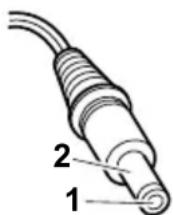
(16-10V)
| Pin Voltage (V dc) |
| 1 +15.5 to +17.0 |
| 2 Ground |
- If the voltage is not correct, replace the ac adapter.
- If the voltage is acceptable, do the following:
-Replace the system board.
- If the problem persists, go to "Product overview" or page 4.
Note: Noise from the ac adapter does not always indicate a defect.
Checking operational charging
To check whether the battery charges properly during operation, use a discharged battery pack or a battery pack that has less than 50% of the total power remaining when installed in the computer.
Perform operational charging. If the battery status indicator or icon does not turn on, remove the battery pack and let it return to room temperature. Reinstall the battery pack. If the charge indicator or icon still does not turn on, replace the battery pack.
If the charge indicator still does not turn on, replace the system board. Then reinstall the battery pack. If it is still not charged, go to the next section.
Checking the battery pack
Battery charging does not start until the Power Meter shows that less than 95% of the total power remains; under this condition the battery pack can charge to 100% of its capacity. This protects the battery pack from being overcharged or from having a shortened life.
To check the status of your battery, move your cursor to the Power Meter icon in the icon tray of the Windows taskbar and wait for a moment (but do not click), and the percentage of battery power remaining is displayed. To get detailed information about the battery, double-click the Power Meter icon.
Note: If the battery pack becomes hot, it may not be able to charge. Remove it from the computer and leave it at room temperature for a while. After it cools down, reinstall and recharge it.
To check the battery pack, do the following:
- Power off the computer.
- Remove the battery pack and measure the voltage between battery terminals 1 (+) and 5 (−). See the following figure:
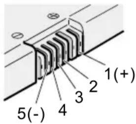
| Terminal Voltage (V dc) | |
| 1 + 0 to + 1 | 2.6 |
| 5 Ground (-) | |
- If the voltage is less than +11.0 V dc, the battery pack has been discharged.
Note: Recharging will take at least 3 hours, even if the indicator does not turn on.
If the voltage is still less than +11.0 V dc after recharging, replace the battery.
- If the voltage is more than +11.0 V dc, measure the resistance between battery terminals 4 and 5. The resistance must be 4 to 30 K Ω.
If the resistance is not correct, replace the battery pack. If the resistance is correct, replace the system board.
Checking the backup battery
Do the following:
- Power off the computer, and unplug the ac adapter from it.
-
Turn the computer upside down.
-
Remove the battery pack (see "1010 Battery pack" or page 60).
- Remove the backup battery (see "Checking the battery back" on page 37).
- Measure the voltage of the backup battery. See the following figure.

| Wire Voltage (V dc) | |
| Red +2 | 5 to +3.2 |
| Black Ground | |
- If the voltage is correct, replace the system board.
- If the voltage is not correct, replace the backup battery.
- If the backup battery discharges quickly after replacement, replace the system board.
ThinkPad A20m/p, A21m/p and A22m/p
Product overview. 4 1
Specifications. 4 1
Status indicators. 4 4
FRU tests . 4 6
Fn key combinations . . . . . . . . . 4 8
Symptom-to-FRU index . . . . . . . . . 4 9
Numeric error codes . . . . . . . . . 4 9
Error messages . . . . . . . . . . . 5 2
Beep symptoms. 5 3
No beep symptoms. 5 3
LCD-related symptoms. 5 4
Intermittent problems . . . . . . . . . . 5 5
Undetermined problems . . . . . . . . . 5 5
FRU replacement notices . . . . . . . . . 5 6
Screw notices . . . . . . . . . . . . 5 6
Retaining serial numbers. 57
Restoring the serial number of the system unit 57 Retaining the UUID . . . . . . . . . . 5 7
Removing and replacing a FRU. 5 9
1010 Battery pack. 6 0
1020 DIMM. 6 1
1030 Mini PCI adapter . . . . . . . . 6 3
For A20m/p, A21m/p series . . . . . . . 6 4 For A22m/p series . . . . . . . . 6 5
1040 Backup battery . . . . . . . . . 6 6
1050 Hard-disk drive or RF ID adapter . . . . 6 7
1060 Ultrabay 2000 device . . . . . . . . 6 9
1070 Keyboard 7 1
1080 Keyboard CRU insulator . . . . . . 7 4
1090 Hinge cover and clear sheet icon . . . . 7 5
1100 Keyboard bezel and speaker. . . . . . 7 6
1110 Microphone and speaker cable . . . . . 7 8
For A20m/p and A21m/p series (microphone and speaker cable) . . . . . . . . . . 7 8
For A22m/p series (speaker cable) . . . . . 7 9
1120 Sub card. 8 0
1130 PC Card slot assembly ..... 82
1140 Fan assembly . . . . . . . . . . 8 3
1150 Diskette drive . . . . . . . . . 8 5
1160 Upper shield. 8 7
1170 TV card . . . . . . . . . . . . 8 8
1180 CPU socket and CPU . . . . . . . 8 9
1190 System board and RJ45/11 connector assembly 9 1
For A20m/p and A21m/p series . . . . . . 9 2
For A22m/p series . . . . . . . . . 9 2
Thermal rubbers location. 9 3
2010 LCD assembly . . . . . . . . . . 9 4
2020 Front bezel . . . . . . . . . . . 9 6
12.1-in. panel . . . . . . . . . . 9 6
14.1-in. and 15.0-in. panels . . . . . . . 9 7
2030 Inverter card . . . . . . . . . 9 9
12.1-in. panel . . . . . . . . . . . 9 9
14.1-in. and 15.0-in. panels . . . . . . 1 0 0
2040 LCD panel . . . . . . . . . . 1 0 1
12.1-in. panel. 1 0 1
14.1-in. and 15.0-in. panels . . . . . . 1 0 3
3010 ThinkPad Dock PCI cover . . . . . 1 0 5
3020 ThinkPad Dock top cover . . . . . . 1 0 7
Locations . . . . . . . . . . . . . . . 1 1 2
Front view. 1 1 2
Rear view. 1 1 3
Bottom view. 1 1 4
Parts list . . . . . . . . . . . . . . 1 1 5
A series model matrix . . . . . . . . 1 1 5
Overall. 1 2 3
AC adapter . . . . . . . . . . . . 1 3 6
LCD FRUs. 1 3 6
12.1-in. SVGA TFT . . . . . . . . 1 3 6
14.1-in. XGA TFT . . . . . . . . 1 3 7
15.0-in. XGA TFT (LG) . . . . . . . 1 3 8
15.0-in. XGA TFT (SAMSUNG) . . . . . 1 3 8
15.0-in. SXGA+ TFT . . . . . . . 1 3 9
15.0-in. UXGA TFT . . . . . . . . 1 3 9
Keyboard. 1 4 0
Recovery CDs 1 4 1
For Windows 98 (A22m) . . . . . . . 1 4 1
For Windows 98 (A22p) . . . . . . . 1 4 2
For Windows 2000 (A22m). . . . . . . 1 4 3
For Windows 2000 (A22p) . . . . . . . 1 4 3
For Windows 2000/Windows NT (A22m) 143
For Windows 2000/Windows NT (A22p) ... 144
Miscellaneous parts. 1 4 5
Optional FRUs . . . . . . . . . . . 1 4 7
Common parts list . . . . . . . . . 1 4 8
Tools. 1 4 8
Power cords (system) . . . . . . . . 1 4 8
Power cords (docking station) . . . . . . 1 4 9
Notices 1 5 0
Trademarks. 1 5 0
Product overview
This section presents the following product-unique information:
- "Specifications"
• "Status indicators" on page 44 - "FRU tests" on page 46
- "Fn key combinations" on page 48
Specifications
The following table lists the specifications of the ThinkPad A20m/p, A21m/p and A22m/p series:
| Feature Description | |
| Processor A20m | Intel®Celeron®processor 500 MHz, L2 256-KB cacheIntel®Celeron®processor 550 MHz, L2 256-KB cacheMobile Intel®Pentium®III processor 500 MHz, L2 256-KB cacheMobile Intel®Pentium®III processor at 600 MHz featuring Intel®SpeedStepTM technologyMobile Intel®Pentium®III processor at 650 MHz featuring Intel®SpeedStepTM technologyMobile Intel®Pentium®III processor at 700 MHz featuring Intel®SpeedStepTM technologyA20pMobile Intel®Pentium®III processor at 700 MHz featuring Intel®SpeedStepTM technologyMobile Intel®Pentium®III processor at 750 MHz featuring Intel®SpeedStepTM technologyA21mMobile Intel®Pentium®III processor at 700 MHz featuring Intel®SpeedStepTM technologyMobile Intel®Pentium®III processor at 750 MHz featuring Intel®SpeedStepTM technologyMobile Intel®Pentium®III processor at 800 MHz featuring Intel®SpeedStepTM technology |
(continued)
| Feature Description | |
| Processor A21p | •Mobile Intel® Pentium® III processor at 850 MHz featuring Intel® SpeedStepTM technologyA22m•Mobile Intel® Pentium® III processor at 800 MHz featuring Intel® SpeedStepTM technology•Mobile Intel® Pentium® III processor at 850 MHz featuring Intel® SpeedStepTM technology•Mobile Intel® Pentium® III processor at 900 MHz featuring Intel® SpeedStepTM technology•Mobile Intel® Pentium® III processor at 1 GHz featuring Intel® SpeedStepTM technologyA22p•Mobile Intel® Pentium® III processor at 1 GHz featuring Intel® SpeedStepTM technology |
| Bus architecture PCI Bus | |
| Memory (standard) A20m/p | •64 MB (on the system board)•128 MB (on the system board)A21m/p•64 MB (on the system board)•128 MB (on the system board)•64 MB (64 MB SO-DIMM × 1)•128 MB (128 MB SO-DIMM × 1)A22m/p•64 MB (64 MB SO-DIMM × 1)•128 MB (128 MB SO-DIMM × 1) |
| Memory (optional) 64 MB, 128 MB, or 256 MB DIMM card (maximum of 512 MB) | |
| CMOS RAM 114 bytes + 128 bytes | |
| Display •12.1-inch, 16M colors, SVGA (800·600 resolution) TFT color LCD•14.1-inch, 16M colors, XGA (1024·768 resolution) TFT color LCD•15.0-inch, 16M colors, XGA (1024·768 resolution) TFT color LCD•15.0-inch, 16M colors, SXGA+ (1400·1050 resolution) TFT color LCD•15.0-inch, 16M colors, UXGA (1600·1200 resolution) TFT color LCD | |
(continued)
| Feature Description | |
| Diskette drive 1.44 MB | (3-mode), 3.5-inch |
| Hard-disk drive A20m/p | 6.0 GB, 2.5-inch, IDE interface12.0 GB, 2.5-inch, IDE interface18.0 GB, 2.5-inch, IDE interface20.0 GB, 2.5-inch, IDE interfaceA21m/p10.0 GB, 2.5-inch, IDE interface20.0 GB, 2.5-inch, IDE interface32.0 GB, 2.5-inch, IDE interfaceA22m/p10.0 GB, 2.5-inch, IDE interface20.0 GB, 2.5-inch, IDE interface30.0 GB, 2.5-inch, IDE interface32.0 GB, 2.5-inch, IDE interface |
| I/O port •External monitor | Line-inHeadphoneMicrophoneMouse or keyboardParallelPort replicator connectorSerialUniversal serial bus (USB) connectorRJ11RJ45TV-in/out (for MT2629)TV-out (for MT2628-Fxx, Gxx, Sxx, Txx, MT2623-Gxx, Txx) |
| Internal modem 56.6 Kbps | |
| Audio •Internal microphone | (for A20m/p,A21m/p)Internal speakerSoftware control volume |
| Infrared transfer IrDA 1 | 1 |
| PC Card One Type-III | or two Type-II |
| AC adapter 72-watt type | |
| Bay device A20m/p | 10-24 x CD-ROM drive6 x DVD driveA21m/p, A22m/p10-24 x CD-ROM drive8 x DVD drive |
Status indicators
The system status indicators show the status of the computer, as follows:
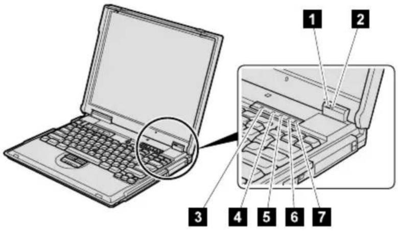
| Indicator Meaning | |
| 1 Battery Green | The battery is fully charged.Blinking green:The battery has enough power to operate, but is being charged.Orange: The battery power is low. The battery is to being charged.Blinking orange:The battery needs to be charged.when the indicator starts blinking orange, the computer beeps three times. |
| 2 Standby status | Green: The computer is in standby mode.Blinking green:The computer is entering standby mode or hibernation mode, or is resuming normal operation. This indicator does not blink in Windows 2000 and Windows Me. |
| 3 Drive in use | Green: Data is being read from or written to the hard-disk drive, the diskette drive, or the drive in the Ultrabay 2000.When this indicator is on, do not put the computer into standby mode or turn off the computer.Note: Do not move the system while the Green drive in use light is on. Sudden physical shock could cause drive errors. |
(continued)
| Indicator Meaning | |
| 4 Num lock Green: The numeric keypad on the keyboard is enabled. To enable or disable the keypad, press and hold the Shift key while pressing the NumLk key. | |
| 5 Caps lock Green: Caps Lock mode is enabled. To enable or disable Caps Lock mode, press Caps Lock key. | |
| 6 Scroll lock | Green: Scroll Lock mode is enabled. Arrow keys can be used as screen-scroll function keys, but not to move the cursor. To enable or disable Scroll Lock mode, press ScrLk key. Not all application programs support this function. |
| 7 Power on Green: This indicator stays lighted whenever the computer is on. If the power-on indicator is on and the standby indicator is off, the system is ready to use. If both the power-on indicator and the standby indicator are on, you can use the computer after it returns from the standby mode and the standby indicator goes off. | |
FRU tests
The following table shows the test for each FRU.
| FRU Applicable | test |
| System board 1. | Diagnostics --> CPU/Coprocessor2. Diagnostics --> Systemboard |
| Power | Diagnostics --> Other Devices --> IBM AC Adapter, IBM Battery 1 (IBM Battery 2) |
| LCD unit 1. | Diagnostics --> Video Adapter2. Interactive Tests --> Video |
| Modem 1. Make sure the modem is set up correctly.2. Replace the modem jack and the modem card in turn, and run the following test in Diagnostics --> Communication:a. Lucent Modem (M2) Loopbackb. Lucent Modem (M2) Dialtone/DTMc. Intel Modem Registerd. Intel Modem Loopback/DTMFe. Intel SP Modem Registerf. Intel SP Modem Loopback/DTMfg. 3Com MiniPCI Modem Testh. 3Com MiniPCI Dialtone Test | |
| Audio 1. Interactive Tests --> Internal Speaker2. Diagnostics --> Other Devices --> Crystal SoundFusionTM Test | |
| Speaker Interactive Tests --> Internal Speaker | |
| PC Card slots | Diagnostics --> Systemboard --> PCMCIA, PCMCIA External Loop |
| Keyboard 1. Diagnostics --> Systemboard --> Keyboard2. Interactive Tests --> Keyboard | |
| TrackPoint or pointing device | If the TrackPoint does not work, check the configuration in the ThinkPad Configuration program. If the TrackPoint is disabled, select Enable to enable it.After you use the TrackPoint, the pointer may drift on the screen for a short time. This drift can occur when a slight, steady pressure is applied to the TrackPoint pointer. This symptom is not a hardware problem. If the pointer stops after a short time, no service action is necessary.If enabling the TrackPoint does not correct the problem, continue with the following:•Interactive Tests --> Mouse |
| Hard-disk drive | Diagnostics --> Fixed Disks |
| Diskette drive | 1. Diagnostics --> Diskette Drives2. Interactive Tests --> Diskette |
(continued)
| FRU Applicable | test |
| CD-ROM or DVD drive | 1. Diagnostics --> Other Devices --> CD-ROM/DVD2. Interactive Tests --> CD-ROM/DVD Test |
| Memory 1. If two | DIMMs are installed, remove one of them and run Diagnostics --> Memory Test - Quick.2. If the problem does not recur, return the DIMM to its place, remove the other one, and run the test again.3. If the test does not detect the error, run Diagnostics --> Memory Test - Full. |
| Fan 1. Turn on the | computer and check the air turbulence at the louver near the power switch.Run Diagnostics --> Other Devices --> IBM Fan. |
Fn key combinations
The following table shows the function of each combination of Fn with a function key.
| Key combination | Description |
| Fn + F1 Reserved. | |
| Fn + F2 Reserved. | |
| Fn + F3 Turn off the LCD display, leaving the screen blank. To turn the LCD display on again, press any key or the TrackPoint stick. | |
| Fn + F4 Turn standby mode on. To return to normal operation, press the Fn key independently, without pressing a function key. | |
| Fn + F5 Reserved. | |
| Fn + F6 Reserved. | |
| Fn + F7 Switch between the LCD and an external monitor (CRT). If an external monitor is attached, computer output is displayed in the following three patterns by turns:•CRT display•LCD + CRT display•LCD | |
| Fn + F8 Turn screen expansion on or off. (There is no symbol on the key.) | |
| Fn + F9 Reserved. | |
| Fn + F10 Reserved. | |
| Fn + F11 Reserved. | |
| Fn + F12 Turn hibernation mode on. To return to normal operation, press the power button for less than four seconds. | |
| Fn + PgUp Turn the ThinkLight on or off. | |
| Fn + Home The LCD becomes brighter. | |
| Fn + End The LCD becomes less bright. |
Symptom-to-FRU index
The symptom-to-FRU index in this section lists symptoms and errors and their possible causes. The most likely cause is listed first, in boldface type.
Note: Do the FRU replacement or other actions in the sequence shown in the column headed "FRU or action, in sequence." If replacing a FRU does not solve the problem, put the original part back in the computer. Do not replace a nondefective FRU.
This index can also help you determine, during regular servicing, what FRUs are likely to need to be replaced next.
A numeric error is displayed for each error detected in POST or system operation. In the displays, n can be any number.
If no numeric code is displayed, check the narrative descriptions of symptoms. If the symptom is not described there, go to "Intermittent problems" on page 55.
Note
For an IBM device not supported by diagnostic codes in the ThinkPad notebook computers, see the manual for that device.
Numeric error codes
| Symptom or error FRU or action, in sequence | |
| 0175Bad CRC1, stop POST task —The EEPROM checksum is not correct. | System board. |
| 0187EAIA data access error — The access to EEPROM has failed. | System board. |
| 0188Invalid RFID serialization information area or bad CRC2 — The EEPROM checksum is not correct. | System board. |
| 0189Invalid RFID configuration information area — The EEPROM checksum is not correct. | System board. |
(continued)
| Symptom or error FRU or action, in sequence | |
| 0190Critical low battery error. | 1. Charge the battery pack.2. Battery pack. |
| 0193RF antenna has been removed. | Enter the supervisor password. |
| 0194The computer has been carried through a security gate. | Enter the supervisor password. |
| 0200Hard disk error — The hard disk is not working. | 1. Reseat the hard-disk drive.2. Load Setup Defaults in IBM BIOS Setup Utility.3. Hard-disk drive.4. System board. |
| 021xStuck key — Keyboard error. | Run interactive tests of the keyboard and the auxiliary input device. |
| 0220Monitor type error — Monitor type does not match the one specified in CMOS. | Load Setup Defaults in IBM BIOS Setup Utility. |
| 0230Shadow RAM error — The shadow RAM failure at offset nnnn. | System board. |
| 0231System RAM error — System RAM failure at offset nnnn. | 1. DIMM.2. System board. |
| 0232Extended RAM error — Extended RAM failure at offset nnnn. | 1. DIMM.2. System board. |
| 0250System battery error — System battery is dead. | Replace the backup battery and run IBM BIOS Setup Utility to reset the time and date. |
| 0251System CMOS checksum bad—Default configuration used. | Replace the backup battery and run IBM BIOS Setup Utility to reset the time and date. |
| 0252Password checksum bad — The password is cleared. | Reset the password by running IBM BIOS Setup Utility. |
| 0260System timer error. | 1. Replace the backup battery and run IBM BIOS Setup Utility to reset the time and date.2. System board. |
(continued)
| Symptom or error FRU or action, in sequence | |
| 0270Real-time clock error. | 1. Replace the backup battery and run IBM BIOS Setup Utility to reset the time and date.2. System board. |
| 0271Date and time error — Neither the date nor the time is set in the computer. | Run IBM BIOS Setup Utility to reset the time and date. |
| 02B2Incorrect drive A type. | 1. Diskette drive.2. External FDD cable.3. I/O card. |
| 02F4EISA CMOS not writable. | 1. Load Setup Defaults in IBM BIOS Setup Utility.2. Replace the backup battery.3. System board. |
| 02F5DIMM test failure. | 1. DIMM.2. System board. |
| 02F6Software NMI failure. | 1. DIMM.2. System board. |
| 02F7Fail-safe timer NMI failure. | 1. DIMM.2. System board. |
Error messages
| Symptom or error FRU or action, in sequence | |
| Device address conflict. 1. Load Setup Defaults in IBM BIOS Setup Utility.2. Backup battery.3. System board. | |
| Allocation error for device. 1. Load Setup Defaults in IBM BIOS Setup Utility.2. Backup battery.3. System board. | |
| Failing bits: nnnn. 1. DIMM. | 2. System board. |
| Invalid system configuration data. | 1. DIMM.2. System board. |
| I/O device IRQ conflict. 1. Load Setup Defaults in IBM BIOS Setup Utility.2. Backup battery.3. System board. | |
| Operating system not found. 1. Check that the operating system has no failure and is installed correctly.2. Enter IBM BIOS Setup Utility and see whether the hard-disk drive and the diskette drive are properly identified.3. Reseat the hard-disk drive.4. Reinstall the operating system.5. Diskette drive.6. Hard-disk drive.7. System board. | |
| Hibernation error. 1. Restore the system configuration to what it was before the computer entered hibernation mode.2. If memory size has been changed, re-create the hibernation file. | |
| Fan error. Fan. | |
Beep symptoms
| Symptom or error FRU or action, in sequence | |
| One beep and a blank, unreadable, or flashing LCD. | 1. Reseat the LCD connector.2. LCD assembly.3. External CRT.4. System board. |
| One long and two short beeps, and a blank or unreadable LCD. | 1. System board.2. LCD assembly.3. DIMM. |
| Two short beeps with error codes. | POST error. See “Numeric error codes” on page 49. |
| Two short beeps with blank screen. | 1. System board.2. DIMM. |
| Two or more beeps, or a continuous beep. Operating System starts successfully. | If a mini-PCI Ethernet card is installed, confirm that Alert On LAN 2 in IBM BIOS Setup Utility is disabled. |
| Three short beeps, pause, three more short beeps, and one short beep. | 1. DIMM.2. System board |
| Only cursor appears. Reinstall operating system. | |
No beep symptoms
| Symptom or error FRU or action, in sequence | |
| No beep, power-on indicator on, LCD blank, and no POST. | 1.Make sure that every connector is connected tightly and correctly.2.DIMM.3.System board. |
| No beep, power-on indicator on, and LCD blank during POST. | 1.Reseat DIMM.2.System board. |
| The power-on password prompt. | A power-on password or a supervisor password is set.Type the password and press Enter. |
| The hard-disk password prompt. | A hard-disk password is set.Type the password and press Enter. |
| The DOS full screen looks smaller. | Start the ThinkPad Configuration program and set theScreen expansion function. |
LCD-related symptoms
Important
The TFT LCD for the notebook computer contains many thin-film transistors (TFTs). A small number of dots that are missing, discolored, or always lighted is characteristic of TFT LCD technology, but excessive pixel problems can cause viewing concerns. The LCD should be replaced if the number of missing, discolored, or lighted dots in any background is:
- SVGA: 5 or more bright dots, 5 or more dark dots, or a total of 9 or more bright and dark dots.
•XGA: 8 or more bright dots, 8 or more dark dots, or a total of 9 or more bright and dark dots. - SXGA+: 11 or more bright dots, 13 or more dark dots, or a total of 16 or more bright and dark dots.
- UXGA: 11 or more bright dots, 16 or more dark dots, or a total of 16 or more bright and dark dots.
Note: A bright dot is a white or colored pixel that is always on. A dark dot is a pixel that is always off and shows as black.
| Symptom or error FRU or action, in sequence | |
| No beep, power-on indicator on, and a blank LCD during POST. | System board. |
| LCD backlight not working.LCD too dark.LCD brightness cannot be adjusted.LCD contrast cannot be adjusted. | Reseat the LCD connectors.LCD assembly.System board. |
| LCD screen unreadable.Characters missing pixels.Screen abnormal.Wrong color displayed. | See important note for "LCD-related symptoms".Reseat all LCD connectors.LCD assembly.System board. |
| Horizontal or vertical lines displayed on LCD. | LCD assembly. |
Intermittent problems
Intermittent system hang problems can be due to a variety of causes that have nothing to do with a hardware defect, such as cosmic radiation, electrostatic discharge, or software errors. FRU replacement should be considered only when a problem recurs.
When analyzing an intermittent problem, do the following:
- Run the diagnostic test for the system board in loop mode at least 10 times.
- If no error is detected, do not replace any FRUs.
- If any error is detected, replace the FRU shown by the FRU code. Rerun the test to verify that no more errors exist.
Undetermined problems
You are here because the diagnostic tests did not identify which adapter or device failed, wrong devices are installed, a short circuit is suspected, or the system is inoperative. Follow these procedures to isolate the failing FRU (do not isolate FRUs that have no defects).
Verify that all attached devices are supported by the computer.
Verify that the power supply being used at the time of the failure is operating correctly. (See "Power system checkout" on page 35.)
- Power off the computer.
- Visually check each FRU for damage. Replace any damaged FRU.
-
Remove or disconnect all of the following devices:
a. Non-IBM devices
b. Devices attached to the port replicator
c. Printer, mouse, and other external devices
d. Battery pack
e. Hard-disk drive
f. External diskette drive
g. DIMM
h. CD-ROM and diskette drive in the UltraslimBay
i. PC Cards -
Power on the computer.
-
Determine whether the problem has changed.
-
If the problem does not recur, reconnect the removed devices one at a time until you find the failing FRU.
-
If the problem remains, replace the following FRUs one at a time (do not replace a nondefective FRU):
a. System board
b. LCD assembly
FRU replacement notices
This section contains notices related to removing and replacing parts. Read this section carefully before replacing any FRU.
Screw notices
Loose screws can cause a reliability problem. In IBM ThinkPad computer, this problem is addressed with special nylon-coated screws that have the following characteristics:
•They maintain tight connections.
•They do not easily come loose, even with shock or vibration.
•They are harder to tighten.
•They should be used only once.
Do the following when you service this machine:
- Keep the screw kit (for the P/N, see "Miscellaneous parts" on page 145) in your tool bag.
•Always use new screws.
- Use a torque screwdriver if you have one.
Tighten screws as follows:
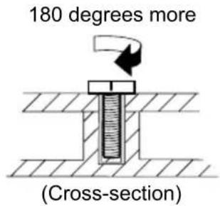
- Plastic to plastic
Turn an additional 90 degrees after the screw head touches the surface of the plastic part:
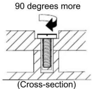
- Logic card to plastic
Turn an additional 180 degrees after the screw head touches the surface of the logic card:
- Torque driver
If you have a torque driver, refer to the "Torque" column for each step.
- Make sure you use the correct screw. If you have a torque screwdriver, tighten all screws firmly to the torque shown in the table. Never use a screw that you removed. Use a new one. Make sure the screws are tightened firmly.
Retaining serial numbers
This section includes the following descriptions:
- “Restoring the serial number of the system unit”
- "Retaining the UUID"
Restoring the serial number of the system unit
When the computer was manufactured, the EEPROM on the system board was loaded with the serial numbers of the system and all major components. These numbers need to remain the same throughout the life of the computer.
If you replace the system board, you must restore the serial number of the system unit to its original value.
Before replacing the system board, save the original serial number by doing the following:
-
Install the ThinkPad hardware maintenance diskette version 1.62, and restart the computer.
-
From the main menu, select 1. Set System Identification.
-
Select 2. Read S/N data from EEPROM.
The serial number for each device is displayed. Write down the serial number of the system unit, designated as follows:
20: System unit serial number
After you have replaced the system board, restore the serial number by doing the following:
-
Install the ThinkPad hardware maintenance diskette version 1.62 and restart the computer.
-
From the main menu, select 1. Set System Identification.
-
Select 1. Add S/N data from EEPROM.
Follow the instructions on the screen.
Note: The serial number of the system unit is written on the label attached on the bottom of the computer.
Retaining the UUID
The Universally Unique Identifier (UUID) is a 128-bit number uniquely assigned to your computer at production and stored in the EEPROM of your system board. The algorithm that generates the number is designed to provide
unique IDs until the year A.D. 3400. No two computers in the world have the same number.
When you replace the system board, you must set the UUID on the new system board as follows:
- Install the ThinkPad hardware maintenance diskette version 1.62, and restart the computer.
- From the main menu, select 4. Assign UUID.
A new UUID is created and written. If a valid UUID already exists, it is not overwritten.
Removing and replacing a FRU
This section presents directions and drawings for use in removing and replacing a FRU. Be sure to observe the following general rules:
- Do not try to service any computer unless you have been trained and certified. An untrained person runs the risk of damaging parts.
- Before replacing any FRU, review "FRU replacement notices" on page 56.
- Begin by removing any FRUs that have to be removed before the failing FRU. Any such FRUs are listed at the top of the page. Remove them in the order in which they are listed.
- Follow the correct sequence in the steps for removing the FRU, as indicated in the drawings by the numbers in square callouts.
- When turning a screw to replace a FRU, turn it in the direction indicated by the arrow in the drawing.
- When removing the FRU, move it in the direction indicated by the arrow in the drawing.
- To put the new FRU in place, reverse the removal procedure and follow any notes that pertain to replacement. For information about connecting and arranging internal cables, see "Locations" on page 112.
- When replacing a FRU, use the correct screw as shown in the procedures.

DANGER
Before removing any FRU, power off the computer, unplug all power cords from electrical outlets, remove the battery pack, and then disconnect any interconnecting cables.
Attention: Before the computer is powered on after FRU replacement, make sure that all screws, springs, and other small parts are in place and are not loose inside the computer. Verify this by shaking the computer gently and listening for rattling sounds. Metallic parts or metal flakes can cause electrical short circuits.
Attention: The system board is sensitive to, and can be damaged by, electrostatic discharge. Before touching it, establish personal grounding by touching a ground point with one hand or by using an electrostatic discharge (ESD) strap (P/N 6405959).
1010 Battery pack

DANGER
Use only the battery in the parts listing for your computer. Use of an incorrect battery can result in ignition or explosion of the battery.
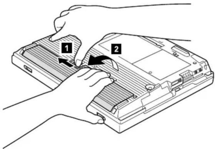
1020 DIMM
For access, remove this FRU:
• "1010 Battery pack" on page 60
Note: Loosen the screw 1, but do not remove it.
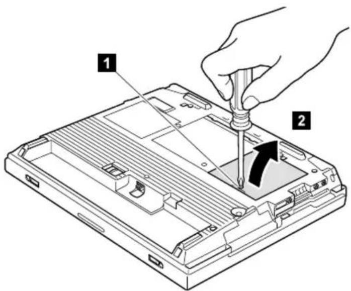
(continued)

When installing: With the notched end of the DIMM toward the socket, insert the DIMM into the socket, then press it firmly. Pivot the DIMM until it snaps into place. Make sure that the card is firmly fixed in the slot and does not move easily.
1030 Mini PCI adapter
For access, remove this FRU:
• "1010 Battery pack" on page 60
Note: Loosen the screw 1, but do not remove it.
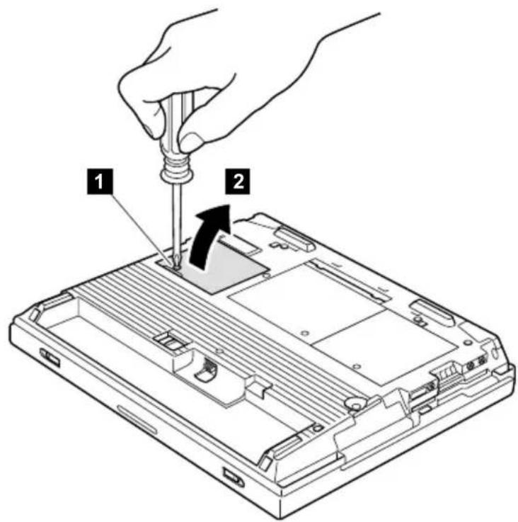
(continued)
For A20m/p, A21m/p series
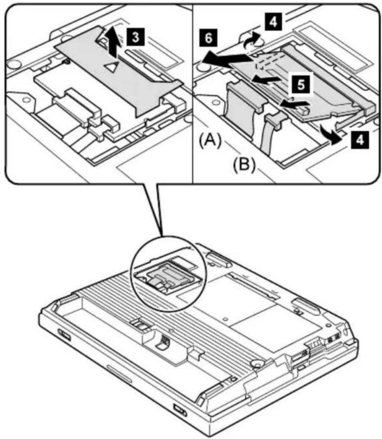
Note: The illustration shows the combo card. Connector (A) is for the LAN feature and (B) is for the modem feature. This slot also supports a Mini PCI modem card or Mini PCI network card. Step 5 depends on the card type. Disconnect either (A), (B) or both.
When installing the card, do the following:
- With the notched end of the card toward the socket, insert the card into the socket, then press it firmly. Pivot the card until it snaps into place. Make sure that the card is firmly fixed in the slot and does not move easily.
- Make sure that the connector (A) is placed under the card when reinstalling the Mini PCI adapter.
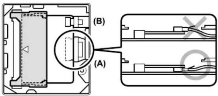
For A22m/p series
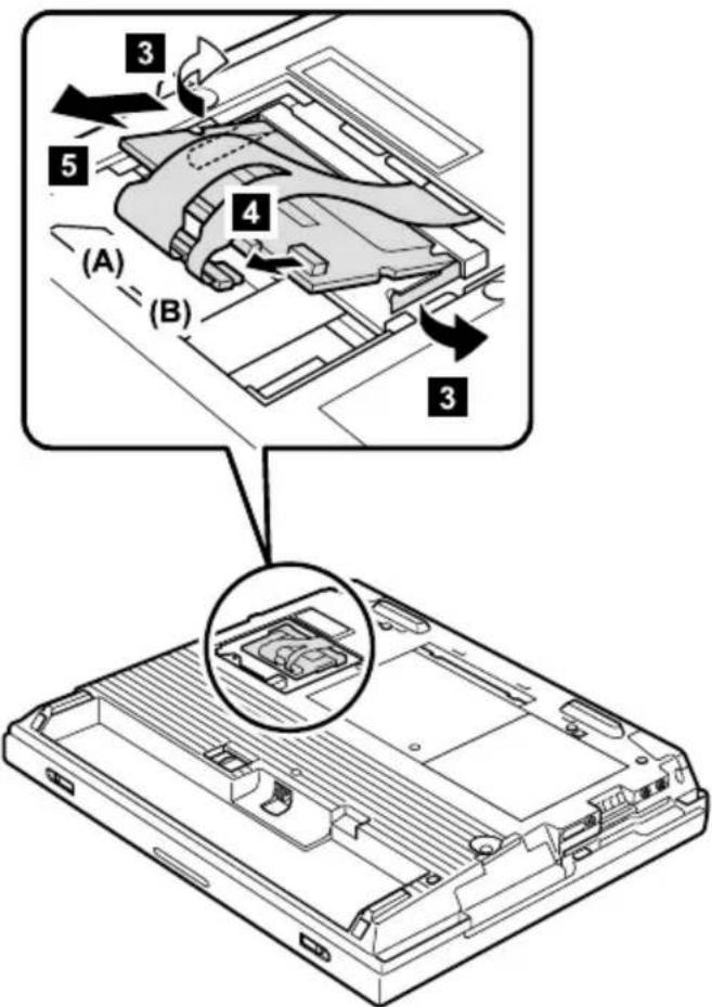
Note: The illustration shows the combo card. Connector (A) is for the LAN feature and (B) is for the modem feature. This slot also supports a Mini PCI modem card or Mini PCI network card. Step 4 depends on the card type. Disconnect either (A), (B) or both.
When installing: With the notched end of the card toward the socket, insert the card into the socket, then press it firmly. Pivot the card until it snaps into place. Make sure that the card is firmly fixed in the slot and does not move easily.
1040 Backup battery

DANGER
Use only the battery in the parts listing for your computer. Use of an incorrect battery can result in ignition or explosion of the battery.
For access, remove these FRUs, in order:
• "1010 Battery pack" on page 60
• "1020 DIMM" on page 61
• "1030 Mini PCI adapter" on page 63
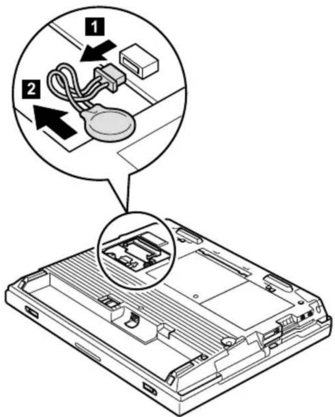
1050 Hard-disk drive or RF ID adapter
Attention
Do not drop or apply any shock to the hard-disk drive. The hard-disk drive is sensitive to physical shock. Incorrect handling can cause damage and permanent loss of data.
Before removing the drive, have the user make a backup copy of all the information on the drive if possible.
Never remove the drive while the system is operating or is in suspend mode.
For access, remove this FRU:
• "1010 Battery pack" on page 60

Note: The hard disk is attached to the cover.
| Step Screw (quantity) |
| 1 Coin screw (1) or security screw (1) |
| Note: Use a 2.5-mm Allen wrench to remove the security screw. |
Removing and replacing a FRU
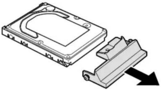
natural_image
Technical illustration of a hard disk assembly with a clamping mechanism, showing internal components and a downward arrow (no text or symbols)When installing: Make sure that the HDD connector is firmly connected.
1060 Ultrabay 2000 device
Any of several devices can be inserted into the Ultrabay 2000. The procedure for installing and removing is the same for every device.
Note: When you release the switch in step 1 the lever pops out. Pull the lever a little in step 2 to release the device from the bay.

(continued)
Removing and replacing a FRU
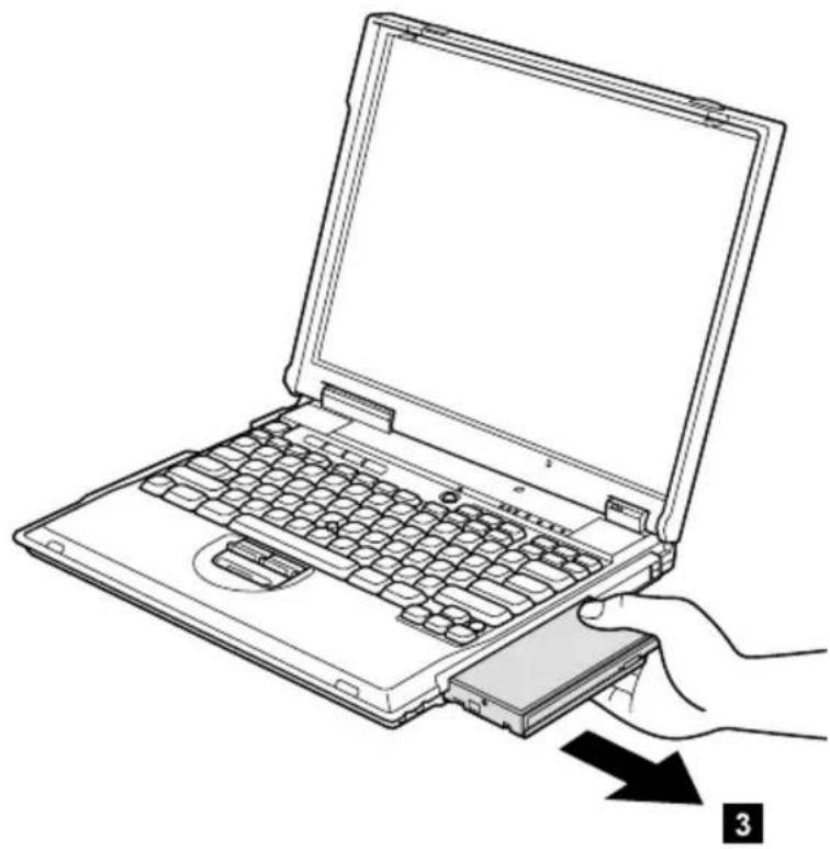
natural_image
Line drawing of a hand inserting a hard drive into a laptop keyboard (no text or symbols)1070 Keyboard
For access, remove these FRUs, in order:
• "1010 Battery pack" on page 60
• "1050 Hard-disk drive or RF ID adapter" on page 67
• "1060 Ultrabay 2000 device" on page 69

| Step Screw (quantity) Torque | ||
| 1 M2.5 | × 15 mm, nylon-coated (3) 0.392 Nm | (4 kgfcm) |
(continued)
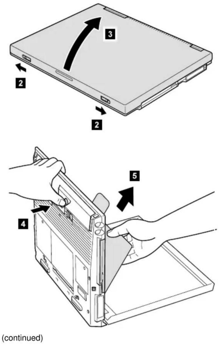
When installing: When installing the keyboard, do as follows:
- Install the new keyboard, following the directions in the figure. Make sure that the keyboard edges, shown in the figure as (A), (B), and (C), are under the frame.
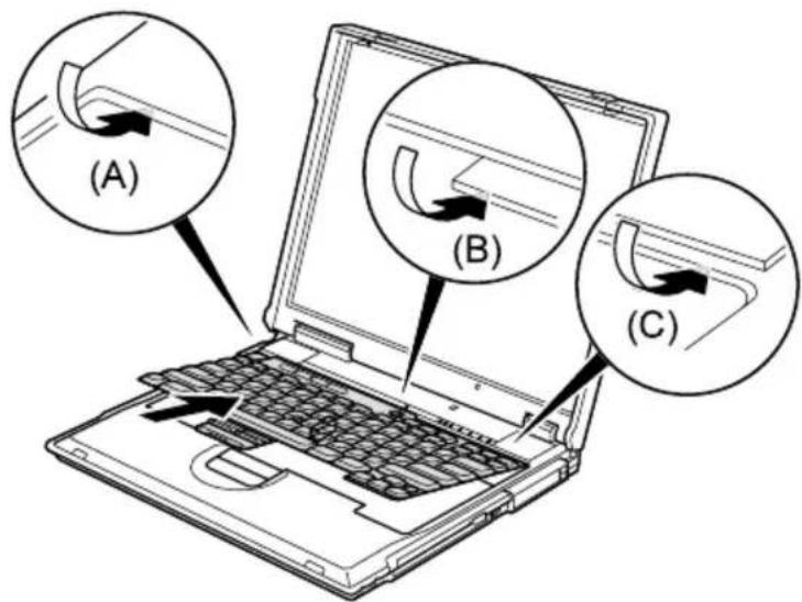
- Push the Y key 1 to connect the keyboard to the connector on the underside of the key; then push the frame of the keyboard 2 to latch the latches.
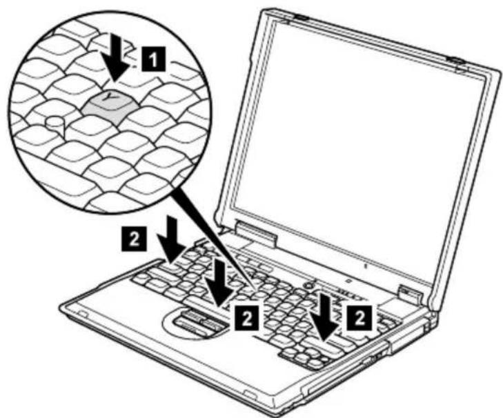
- After the fastening of three screws of bottom side, push the Y key again to connect the keyboard firmly to the connector on the underside of the key.
1080 Keyboard CRU insulator
For access, remove these FRUs, in order:
• "1010 Battery pack" on page 60
- "1050 Hard-disk drive or RF ID adapter" on page 67
• "1060 Ultrabay 2000 device" on page 69
• "10/0 Keyboard" on page 71
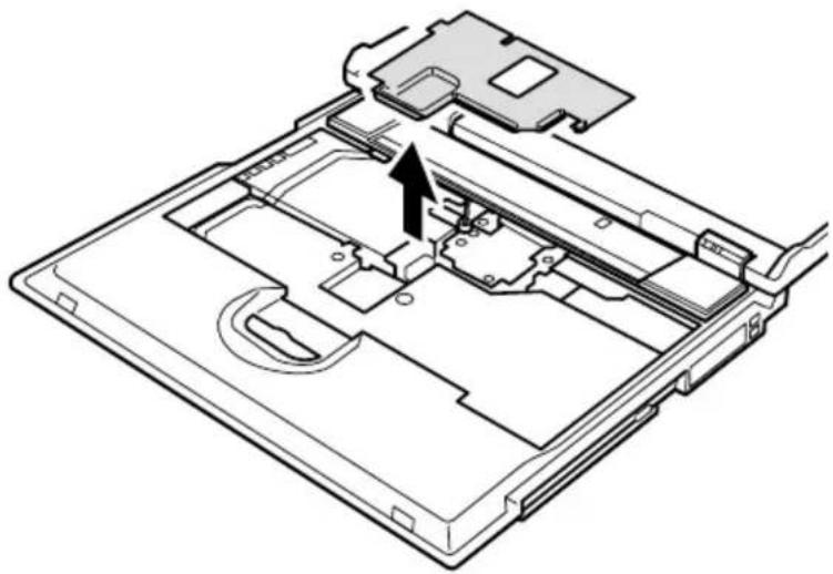
natural_image
Technical line drawing of a computer chassis with an arrow indicating a component (no text or symbols present)1090 Hinge cover and clear sheet icon
For access, remove these FRUs, in order:
• "1010 Battery pack" on page 60
• "1050 Hard-disk drive or RF ID adapter" on page 67
• "1060 Ultrabay 2000 device" on page 69
• "10/0 Keyboard" on page /1
• "1080 Keyboard CRU insulator" on page 74

| Step Screw (quantity) Torque | ||
| 1 M2.5 | × 15 mm, nylon-coated (1) 0.392 Nm | (4 kgfcm) |
When installing: Stick the new clear sheet icon suitable for the model onto the new hinge cover, and then attach it to the computer.

1100 Keyboard bezel and speaker
For access, remove these FRUs, in order:
• "1010 Battery pack" on page 60
- "1050 Hard-disk drive or RF ID adapter" on page 67
• "1060 Ultrabay 2000 device" on page 69
• "10/0 Keyboard" on page /1
• "1080 Keyboard CRU insulator" on page 74
• "1090 Hinge cover and clear sheet icon" on page 75

| Step Screw (quantity) Torque | ||
| 1 M2.5 | × 4.8 mm, nylon-coated (7) 0.392 Nm | (4 kgfcm) |
(continued)
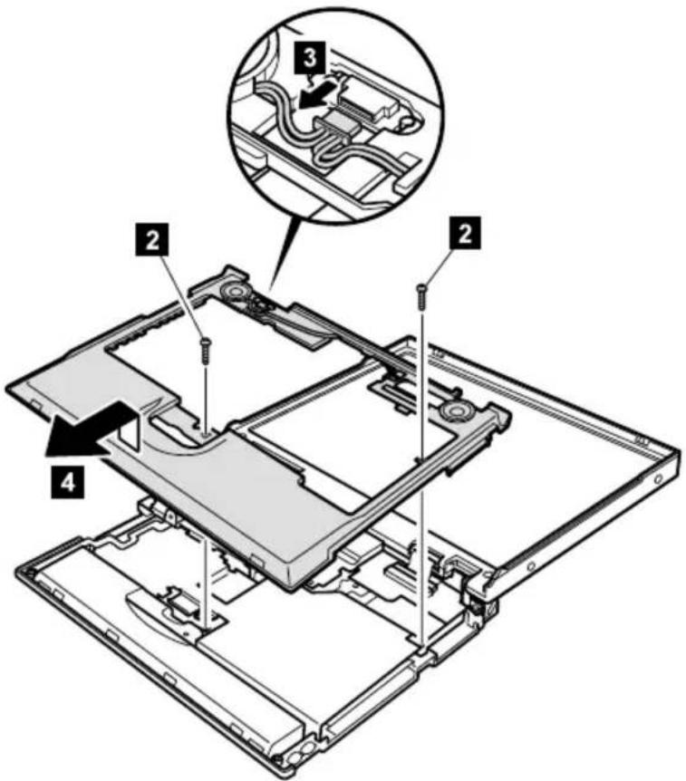
| Step Screw (quantity) Torque | ||
| 2 M2.5 | × 15 mm, nylon-coated (2) 0.392 Nm | (4 kgfcm) |
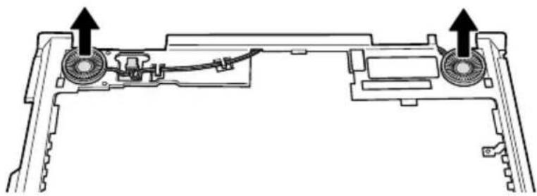
natural_image
Technical line drawing of a mechanical assembly with two circular components and directional arrows indicating movement (no text or symbols)Cable routing: When replacing the cable, see the preceding figure for its cable routing.
1110 Microphone and speaker cable
For access, remove these FRUs, in order:
• "1010 Battery pack" on page 60
• "1050 Hard-disk drive or RF ID adapter" on page 6/
• "1060 Ultrabay 2000 device" on page 69
• "10/0 Keyboard" on page /1
• "1080 Keyboard CRU insulator" on page 74
• "1090 Hinge cover and clear sheet icon" on page 75
• "1100 Keyboard bezel and speaker" on page 76
For A20m/p and A21m/p series (microphone and speaker cable)
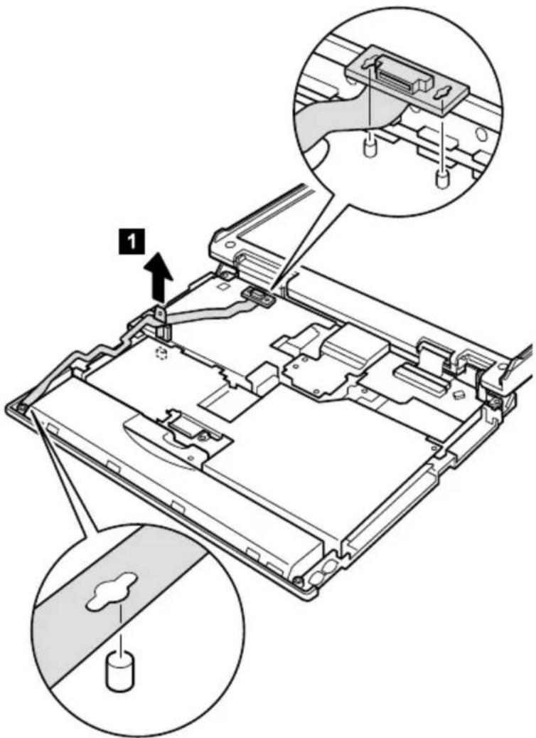
When installing: Make sure that you fasten the connector firmly.
(continued)
For A22m/p series (speaker cable)
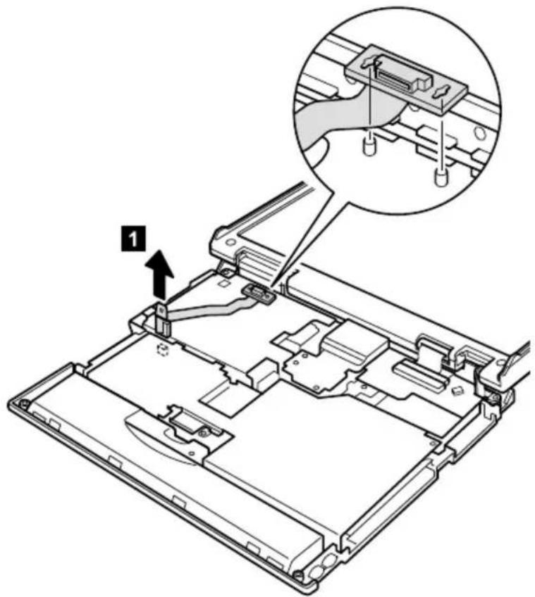
When installing: Make sure that you fasten the connector firmly.
1120 Sub card
For access, remove these FRUs, in order:
• "1010 Battery pack" on page 60
- "1050 Hard-disk drive or RF ID adapter" on page 67
• "1060 Ultrabay 2000 device" on page 69
• "10/0 Keyboard" on page /1
• "1080 Keyboard CRU insulator" on page 74
• "1090 Hinge cover and clear sheet icon" on page 75
• "1100 Keyboard bezel and speaker" on page 76

| Step Screw (quantity) Torque | ||
| 1 M2.6 | × 2.8 mm, nylon-coated (2) 0.392 Nm | (4 kgfcm) |
(continued)
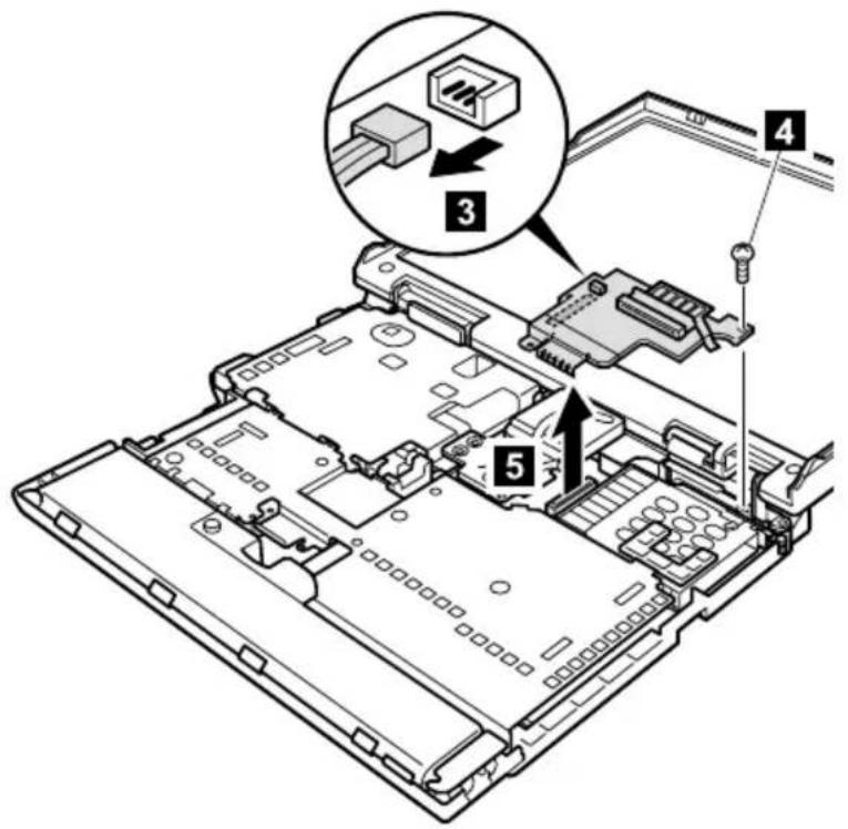
| Step Screw (quantity) Torque | ||
| 4 M2.5 | × 4.8 mm, nylon-coated (1) 0.392 Nm | (4 kgfcm) |
1130 PC Card slot assembly
For access, remove these FRUs, in order:
• "1010 Battery pack" on page 60
• "1050 Hard-disk drive or RF ID adapter" on page 67
• "1060 Ultrabay 2000 device" on page 69
• "10/0 Keyboard" on page /1
• "1080 Keyboard CRU insulator" on page 74
• "1090 Hinge cover and clear sheet icon" on page 75
• "1100 Keyboard bezel and speaker" on page 76
• "1120 Sub card" on page 80
Note: Step 1 (PC Card slot spacer) is only for MT2629.
Other model do not have the spacer. Remove it gently; it will be reused when installing new PC Card slot assembly.
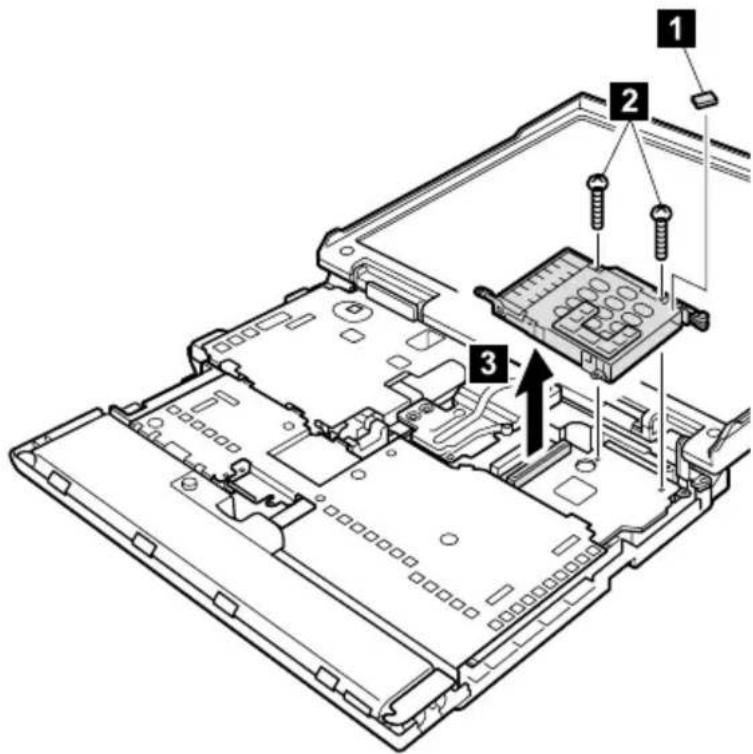
| Step Screw (quantity) Torque | ||
| 2 M2.0 | × 9.5 mm, nylon-coated (2) 0.245 Nm | (2.5 kgfcm) |
1140 Fan assembly
For access, remove these FRUs, in order:
• "1010 Battery pack" on page 60
• "1050 Hard-disk drive or RF ID adapter" on page 67
• "1060 Ultrabay 2000 device" on page 69
• "10/0 Keyboard" on page /1
• "1080 Keyboard CRU insulator" on page 74
• "1090 Hinge cover and clear sheet icon" on page /5
• "1100 Keyboard bezel and speaker" on page 76
Note: Step 1a is for the MT2628-Fxx, Gxx, Pxx, Qxx, Rxx, Sxx, Txx, Xxx, MT2633-Gxx, Txx, and MT2629. Other model do not have the screw 1a.

| Step Screw (quantity) Torque | |
| 1a M2.5 × 4.8 mm, nylon-coated (2) 0.392 Nm | (4 kgfcm) |
| 1 M2.5 × 4.8 mm, nylon-coated (3) 0.392 Nm | (4 kgfcm) |
Installation notice for A21m/p and A22m/p series
When installing the fan assembly, apply the thermal grease (05K5751) on the a -part of the fan as shown in the following figure.

natural_image
Technical line drawing of a mechanical device with a highlighted section and labeled component 'a' (no text or symbols beyond label)1150 Diskette drive
For access, remove these FRUs, in order:
• "1010 Battery pack" on page 60
• "1050 Hard-disk drive or RF ID adapter" on page 67
• "1060 Ultrabay 2000 device" on page 69
• "10/0 Keyboard" on page /1
• "1080 Keyboard CRU insulator" on page 74
• "1090 Hinge cover and clear sheet icon" on page 75
• "1100 Keyboard bezel and speaker" on page /6
• "1110 Microphone and speaker cable" on page 78
Note: Step 1a are for the MT2628-Fxx, Gxx, Pxx, Qxx, Rxx, Sxx, Txx, Xxx, MT2633-Gxx, Txx, and MT2629. Other model do not have the screws 1a.

natural_image
Technical diagram of a computer drive rear panel with connectors and ports (no text or symbols)| Step Screw (quantity) Torque | |
| 1a M2.5 × 4.8 mm, nylon-coated (3) 0.392 Nm | (4 kgfcm) |
(continued)
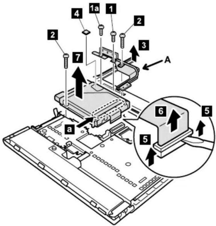
Notes:
-
The heatpipe A and the screw 1a are for the MT2628-Fxx, Gxx, Pxx, Qxx, Rxx, Sxx, Txx, Xxx, MT2633-Gxx, Txx, and MT2629. Other models do not have them.
-
Step 4 (diskette drive spacer) is only for MT2629. Other models do not have the spacer. Remove it gently; it will be reused when installing new diskette drive.
| Step Screw (quantity) Torque | ||
| 1a M2.5 | × 4.8 mm, nylon-coated (1) 0.392 Nm | (4 kgfcm) |
| 1 M2.5 | × 4.8 mm, nylon-coated (1) 0.392 Nm | (4 kgfcm) |
| 2 M2.5 | × 15 mm, nylon-coated (2) 0.392 Nm | (4 kgfcm) |
When installing: Do not press the a -part of the diskette drive to avoid the damage.
1160 Upper shield
For access, remove these FRUs, in order:
• "1010 Battery pack" on page 60
• "1050 Hard-disk drive or RF ID adapter" on page 67
• "1060 Ultrabay 2000 device" on page 69
• "10/0 Keyboard" on page /1
• "1080 Keyboard CRU insulator" on page 74
• "1090 Hinge cover and clear sheet icon" on page 75
• "1100 Keyboard bezel and speaker" on page /6
• "1110 Microphone and speaker cable" on page 78
• "1120 Sub card" on page 80
• "1130 PC Card slot assembly" on page 82
• "1140 Fan assembly" on page 83
• "1150 Diskette drive" on page 85
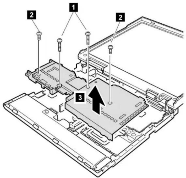
| Step Screw (quantity) Torque | ||
| 1 M2.5 | × 15 mm, nylon-coated (2) 0.392 Nm | (4 kgfcm) |
| 2 M2.5 | × 4.8 mm, nylon-coated (2) 0.392 Nm | (4 kgfcm) |
1170 TV card
Note
This section is only for MT2628-Fxx,-Gxx,-Sxx,-Txx, MT2633-Gxx,-Txx, and MT2629. Other models do not have the TV card.
For access, remove these FRUs, in order:
• "1010 Battery pack" on page 60
• "1050 Hard-disk drive or RF ID adapter" on page 67
• "1060 Ultrabay 2000 device" on page 69
• "10/0 Keyboard" on page 71
• "1080 Keyboard CRU insulator" on page 74
• "1090 Hinge cover and clear sheet icon" on page 75
• "1100 Keyboard bezel and speaker" on page 76
• "1110 Microphone and speaker cable" on page 78
• "1120 Sub card" on page 80
• "1130 PC Card slot assembly" on page 82
• "1140 Fan assembly" on page 83
• "1150 Diskette drive" on page 85
• "1160 Upper shield" on page 8/
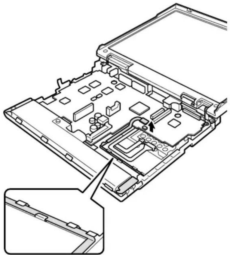
natural_image
Technical line drawing of an electronic device casing with internal components and a highlighted section (no text or symbols)Cable routing: When replacing the modem cable, see the figure for the cable routing.
1180 CPU socket and CPU
For access, remove these FRUs, in order:
• "1010 Battery pack" on page 60
• "1020 DIMM" on page 61
• "1050 Hard-disk drive or RF ID adapter" on page 67
• "1060 Ultrabay 2000 device" on page 69
• "10/0 Keyboard" on page 71
• "1080 Keyboard CRU insulator" on page 74
• "1090 Hinge cover and clear sheet icon" on page /5
• "1100 Keyboard bezel and speaker" on page 76
• "1110 Microphone and speaker cable" on page 78
• "1120 Sub card" on page 80
• "1130 PC Card slot assembly" on page 82
• "1140 Fan assembly" on page 83
• "1150 Diskette drive" on page 85
• "1160 Upper shield" on page 87
Note: MT2628-Exx, -Dxx do not have the CPU removal procedure.
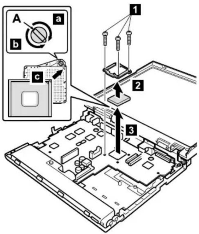
Rotate the screw head (A) 180° to the direction of the arrow a to release the lock and then remove the CPU.
| Step Screw (quantity) Torque | ||
| 1 M2.5 | × 15 mm, nylon-coated (3) 0.392 Nm | (4 kgfcm) |
When installing the CPU, do as shown in the figure.
- Rotate the screw head (A) 180° to the direction of the arrow b to lock the CPU.
- When attach the CPU to the socket, do as shown in the step c.
1190 System board and RJ45/11 connector assembly
For access, remove these FRUs, in order:
• "1010 Battery pack" on page 60
• "1020 DIMM" on page 61
• "1030 Mini PCI adapter" on page 63
• "1040 Backup battery" on page 66
• "1050 Hard-disk drive or RF ID adapter" on page 67
• "1060 Ultrabay 2000 device" on page 69
• "10/0 Keyboard" on page 71
• "1080 Keyboard CRU insulator" on page 74
• "1090 Hinge cover and clear sheet icon" on page 75
• "1100 Keyboard bezel and speaker" on page 76
• "1110 Microphone and speaker cable" on page 78
• "1120 Sub card" on page 80
• "1130 PC Card slot assembly" on page 82
• "1140 Fan assembly" on page 83
• "1150 Diskette drive" on page 85
• "1160 Upper shield" on page 87
• "1170 TV card" on page 88
• "1180 CPU socket and CPU" on page 89
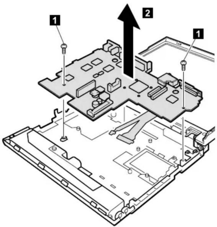
| Step Screw (quantity) Torque | ||
| 1 M2.5 | × 4.8 mm, nylon-coated (2) 0.392 Nm | (4 kgfcm) |
(continued)
Note: Step 4 (thermal rubbers) are only for MT2628-Pxx, -Qxx, -Rxx, -Sxx, -Txx, -Xxx, and MT2629-Hxx, -Uxx. When replacing the system board for those models, remove the thermal rubbers from the removed system board and put them onto the new system board. And then install the new system board to the base cover. (For the location of the therma rubbers, see "Thermal rubbers location" on page 93.)
For A20m/p and A21m/p series
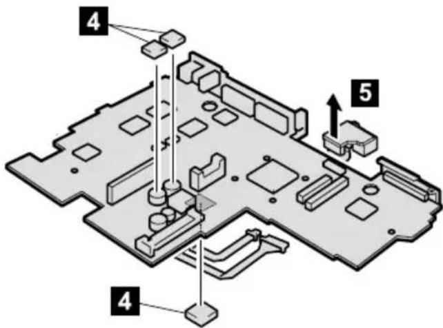
For A22m/p series
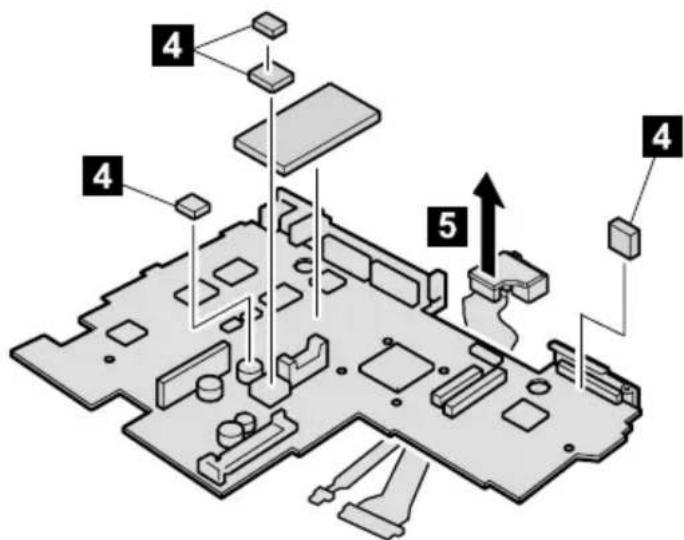
Note: When installing the new RJ45/11 connector assembly onto the system board, make sure that the connector is firmly attached.
Thermal rubbers location
Before installing the new system board, make sure that the thermal rubbers are placed on the system board as shown in the following figures.
For A21m/p series
Upper side of the system board
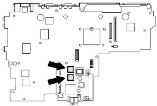
natural_image
Pure electrical circuit lines without any symbolsBottom side of the system board
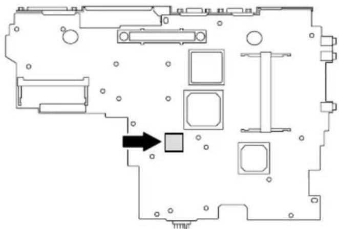
natural_image
Floor plan diagram of a computer room with labeled compartments and a black arrow pointing to a specific area (no text or symbols present)For A22m/p series
Upper side of the system board
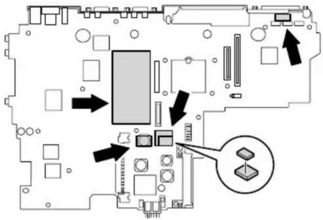
2010 LCD assembly
For access, remove these FRUs, in order:
• "1010 Battery pack" on page 60
• "1050 Hard-disk drive or RF ID adapter" on page 6/
• "1060 Ultrabay 2000 device" on page 69
• "10/0 Keyboard" on page /1
• "1080 Keyboard CRU insulator" on page 74
• "1090 Hinge cover and clear sheet icon" on page 75
• "1100 Keyboard bezel and speaker" on page 76
Note: Screws 1a are for MT2628-Fxx, -Gxx, -Pxx, -Qxx, -Rxx, -Sxx, -Txx, -Xxx, MT2633-Gxx, -Txx and MT2629. Other models do not have them.
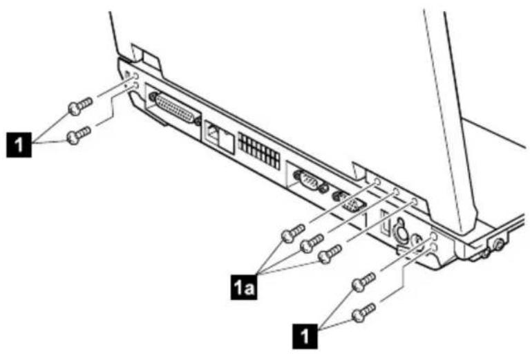
| Step Screw (quantity) Torque | ||
| 1a M2.5 | × 4.8 mm, nylon-coated (3) 0.392 Nm | (4 kgfcm) |
| 1 M2.5 | × 4.8 mm, nylon-coated (4) 0.392 Nm | (4 kgfcm) |
(continued)
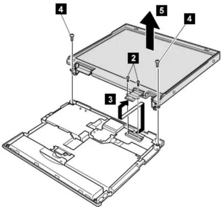
| Step Screw (quantity) Torque | ||
| 2 M2.6 | × 2.8 mm, nylon-coated (2) 0.392 Nm | (4 kgfcm) |
| 4 M2.5 | × 4.8 mm, nylon-coated (2) 0.392 Nm | (4 kgfcm) |
2020 Front bezel
For access, remove these FRUs, in order:
• "1010 Battery pack" on page 60
• "1050 Hard-disk drive or RF ID adapter" on page 67
• "1060 Ultrabay 2000 device" on page 69
• "10/0 Keyboard" on page /1
• "1080 Keyboard CRU insulator" on page 74
• "1090 Hinge cover and clear sheet icon" on page 75
• "1100 Keyboard bezel and speaker" on page 76
• "2010 LCD assembly" on page 94
12.1-in. panel
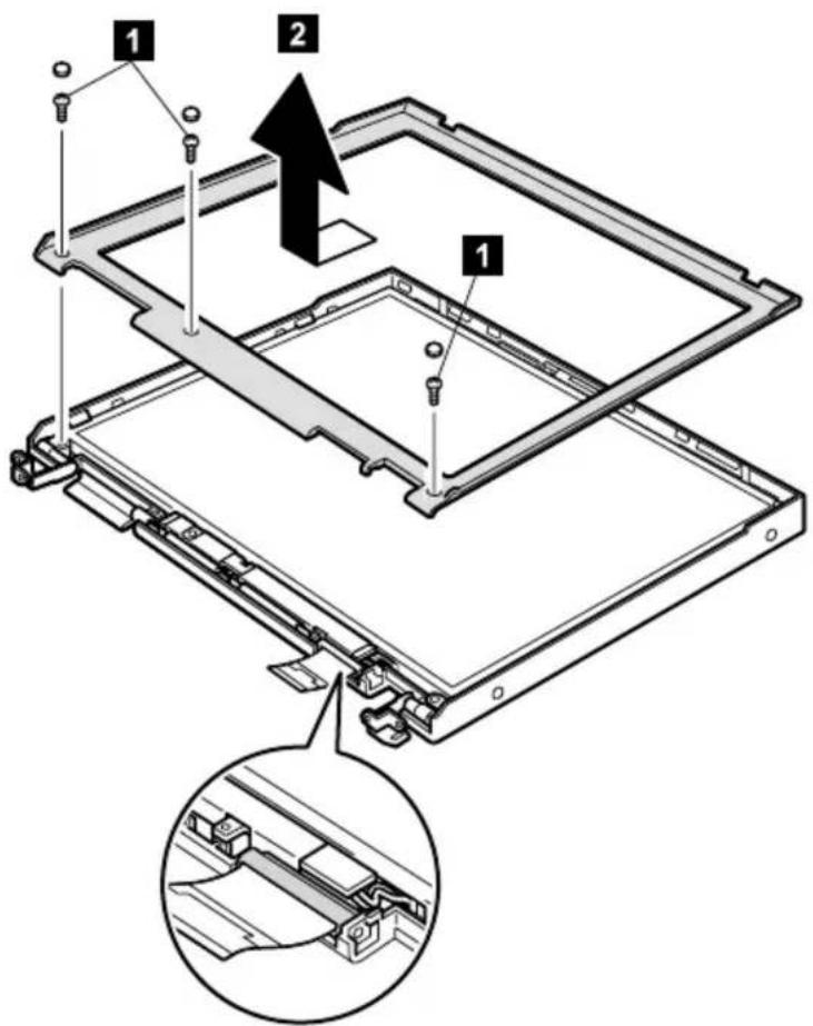
| Step Screw (quantity) Torque | ||
| 1 M2.5 | × 4.8 mm, nylon-coated (3) 0.392 Nm | (4 kgfcm) |
14.1-in. and 15.0-in. panels
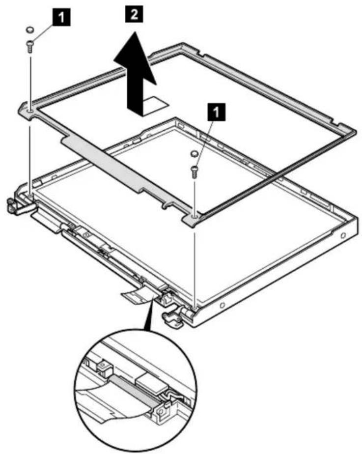
| Step Screw (quantity) Torque | ||
| 1 M2.5 | × 4.8 mm, nylon-coated (2) 0.392 Nm | (4 kgfcm) |
Note: Only the front bezel for the 15.0-in. XGA TFT (LG) has a identifying mark (○), as in the following figure. For the FRU list, see "15.0-in. XGA IFT (LG)" on page 138.
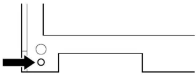
natural_image
Pure technical diagram showing a pipe or channel with circular features and an arrow pointing to a rectangular structure (no text or symbols)2030 Inverter card
For access, remove these FRUs, in order:
• "1010 Battery pack" on page 60
• "1050 Hard-disk drive or RF ID adapter" on page 67
• "1060 Ultrabay 2000 device" on page 69
• "10/0 Keyboard" on page /1
• "1080 Keyboard CRU insulator" on page 74
• "1090 Hinge cover and clear sheet icon" on page /5
• "1100 Keyboard bezel and speaker" on page /6
• "2010 LCD assembly" on page 94
• "2020 Front bezel" on page 96
12.1-in. panel
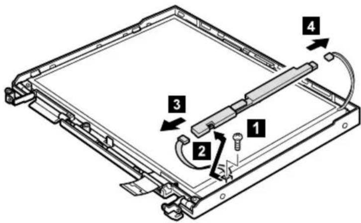
| Step Screw (quantity) Torque | ||
| 1 M2.5 | × 4.8 mm, nylon-coated (1) 0.392 Nm | (4 kgfcm) |
(continued)
14.1-in. and 15.0-in. panels
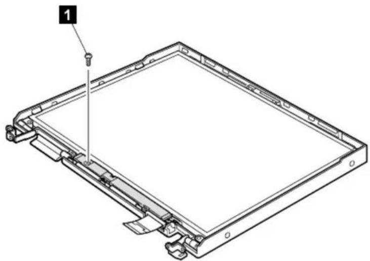
natural_image
Technical line drawing of a rectangular frame with a bolt and mounting bracket (no text or symbols)| Step Screw (quantity) Torque | ||
| 1 M2.5 | × 4.8 mm, nylon-coated (1) 0.392 Nm | (4 kgfcm) |
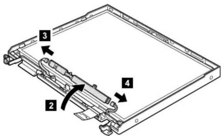
2040 LCD panel
For access, remove these FRUs, in order:
• "1010 Battery pack" on page 60
• "1050 Hard-disk drive or RF ID adapter" on page 67
• "1060 Ultrabay 2000 device" on page 69
• "10/0 Keyboard" on page /1
• "1080 Keyboard CRU insulator" on page 74
• "1090 Hinge cover and clear sheet icon" on page 75
• "1100 Keyboard bezel and speaker" on page /6
• "2010 LCD assembly" on page 94
• "2020 Front bezel" on page 96
• "2030 Inverter card" on page 99
12.1-in. panel
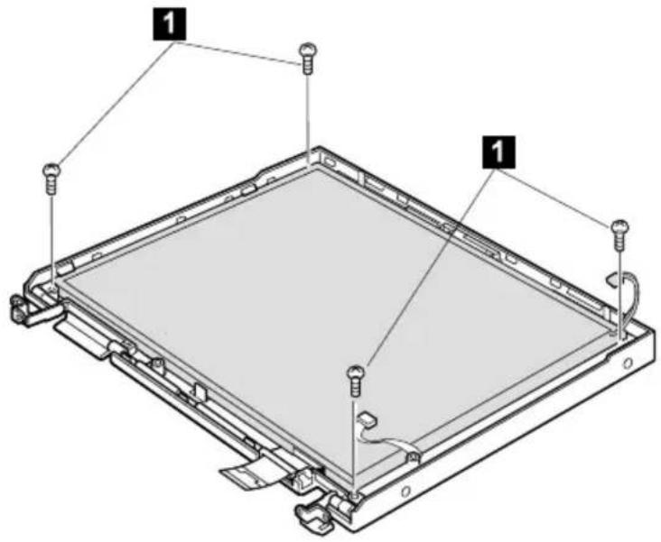
| Step MT Screw (quantity) Torque | |||
| 1 2628 | Dxx, Qxx, 1xx, 2xx | M2.5 × 7.0 mm, nylon-coated (4) | 0.392 Nm (4 kgfcm) |
(continued)
Removing and replacing a FRU
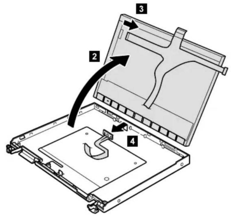
(continued)
14.1-in. and 15.0-in. panels
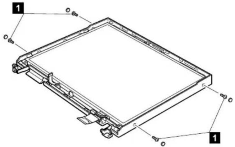
| Step MT Screw (quantity) Torque | |||
| 1 2628 | 3-Fxx, Pxx,Rxx, 3xx | M2 × 5.7 mm,nylon-coated (4) | 0.245 Nm(2.5 kgfcm) |
| 2628-Exx, Gxx,Xxx, Txx and2633-Gxx, Txx, 4xx | M2 × 5.7 mm,nylon-coated (4) | 0.167 Nm(1.7 kgfcm) | |
| 2628-Sxx and2629 | M2 × 5.1 mm,nylon-coated (4) | 0.196 Nm(2.0 kgfcm) | |
(continued)
- For the 14-in. LCD, the LCD cable is taped onto the connector. Tear off the tape before disconnecting the LCD cable in step 4.
•The LCD cable for the 15.0-in. UXGA LCD (27L0598) and the LCD cable for the 15.0-in. SXGA+ LCD (27L0488) have the UltraPort connector and need step 6. If the UltraPort adapter has been screwed onto the LCD, remove the adapter before step 6. To do this, remove the screws from both sides of the adapter as shown in the figure 2a. For other cable, do as shown in the figure 2b.
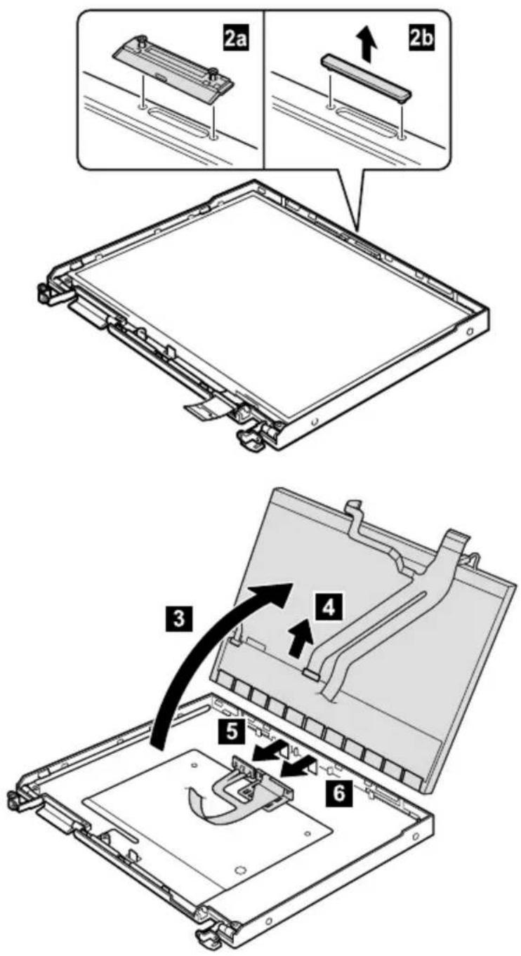
3010 ThinkPad Dock PCI cover
Before replacing the PCI cover:
There are two types of ThinkPad Dock as follows:
- ThinkPad Dock: FRU part no. 08N1546 (PCI cover: FRU part no. 05K6246)

natural_image
Technical line drawing of a mechanical device with mounting holes and internal components (no text or symbols)- ThinkPad Dock with extension plate: FRU part no. 08N1537 (PCI cover: FRU part no. 08N7317)
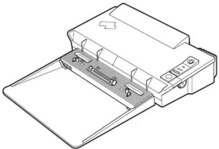
natural_image
Line drawing of a printer with internal components and paper plane (no text or symbols)Make sure that the PCI cover FRU suits the ThinkPad Dock you are servicing.
Note: Following illustration shows the PCI cover removal of ThinkPad Dock (FRU no. 08N1546.) Do the same procedure for the PCI cover removal of ThinkPad Dock with extension plate (FRU part no. 08N1537.)

(Bottom view)
3020 ThinkPad Dock top cover
Note
This section is only for the ThinkPad Dock (FRU no. 08N1546.) Top cover and screw kit for ThinkPad Dock (FRU part no. 12P4143) is not available for the ThinkPad Dock with extension plate (FRU part no. 08N1537.)
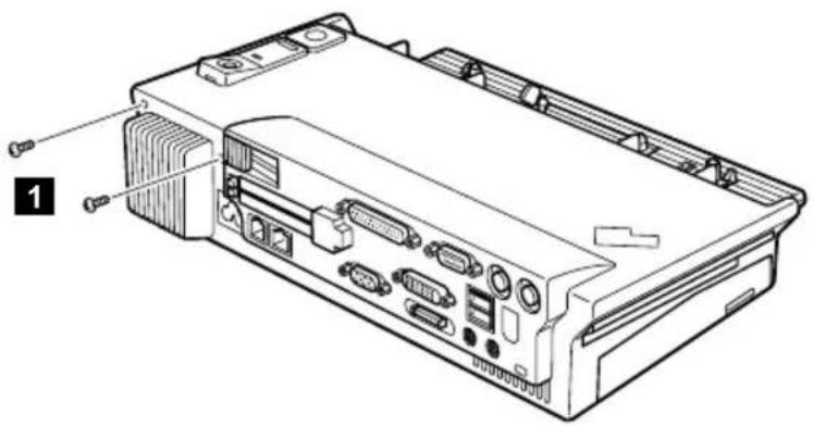
(Rear view)
| Step Screw (quantity) Torque | ||
| 1 M2.5 | × 4.8 mm (2) 0.392 Nm | (4 kgfcm) |
(continued)
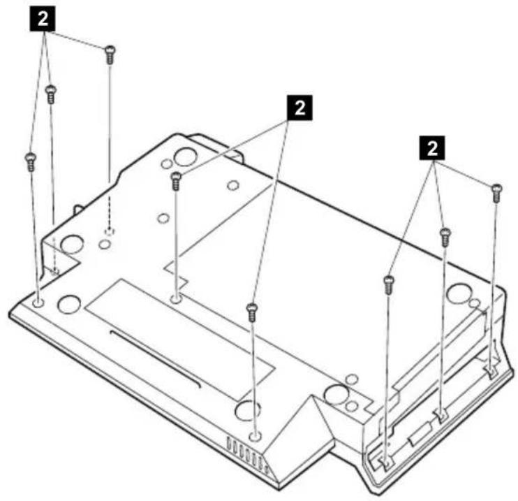
(Bottom view)
| Step Screw (quantity) Torque | ||
| 2 M2.5 | × 4.8 mm (8) 0.392 Nm | (4 kgfcm) |
(continued)
Make sure that the system lock key A is set to the Unlock position. Release the front latches in step 3, and then remove the top cover 4. For step 5, see the inside view, shown in the circle.
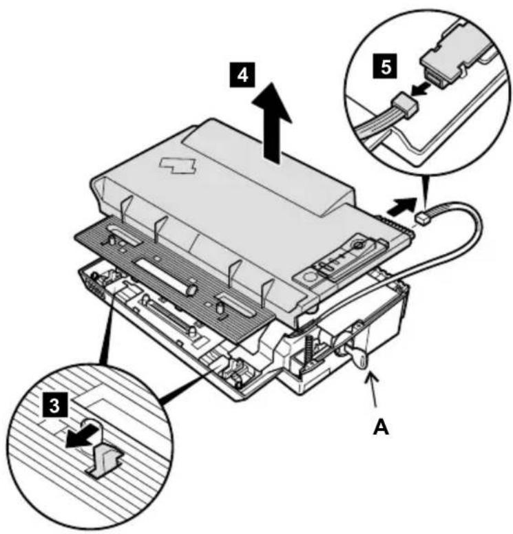
When replacing the top cover, do the following:
•Make sure that the springs placed correctly.
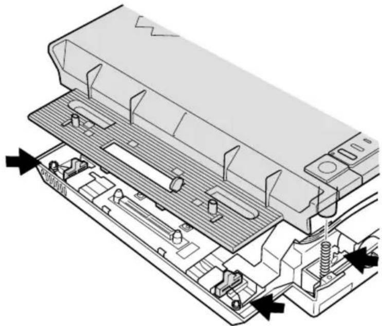
natural_image
Technical diagram of an electronic device showing internal components and directional arrows (no text or symbols)- Make sure that the device release lever is seated correctly.

natural_image
Diagram showing a computer monitor internal structure with an inset close-up of the component (no text or symbols visible)(continued)
Removing and replacing a FRU
•Make sure that the release button works correctly.
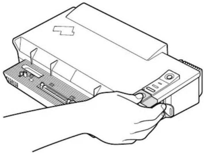
natural_image
Line drawing of a hand inserting a device into a computer case (no text or symbols)Locations
Front view
1 System status indicators
2 Battery and standby mode status indicators
3 Built-in stereo speakers
4 PC Card eject button
5 PC Card slots
6 Bay latch
7 Eject button
8 Ultrabay 2000 device
Note: The Ultrabay 2000 accepts storage devices, such as a DVD drive or a CD-ROM drive.
9 Video-out connector
10 Video-in connector
11 TrackPoint pointing stick
12 TrackPoint buttons
13 ThinkPad button
14 Volume and mute buttons
15 Power switch
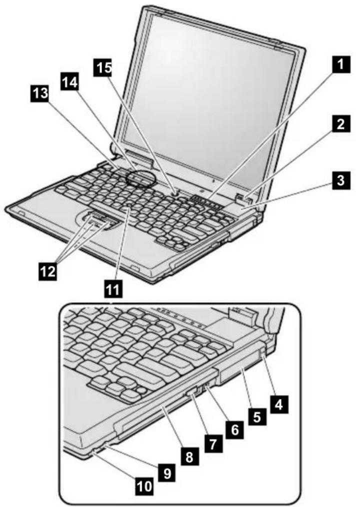
Rear view
1 Security keyhole
2 Parallel connector
3 Modem connector
4 Network connector
5 Serial connector
6 External-monitor connector
7 Universal serial bus (USB) connector
8 External-input-device connector
9 Power jack

Bottom view
1 Battery pack
2 Battery pack latches
3 Mini PCI card slot
4 Docking connector
5 DIMM slot
6 Stereo headphone jack
7 Stereo line-in jack
8 Diskette drive
9 Microphone jack
10 Infrared port
11 Hard-disk drive
12 LCD latches

Parts list
A series model matrix
The A series includes several models. The following table summarizes the characteristics of each model, to help you determine which FRU in the part list meets your need.
| Model CPU Bay | device | Mini PCI adapter | LCD HDD | ||
| A20m (Memory, 64 MB; Video memory, 4 MB) | |||||
| 2628-11x except 11J, 11K2628-12x except 12J, 12K | Cel500— | CD-ROM | Modem 12 | .1-in.SVGA | 6 GB |
| 2628-11J, 11K, 12J, 12K | Ethernet | ||||
| 2628-14x, 1Rx, 1Sx, 1Tx | Combo(Intel) | ||||
| 2628-1Ox — | — | ||||
| 2628-1Ax except 1AJ, 1AK2628-1Cx except 1CJ, 1CK | Cel550— | CD-ROM | Modem 6 | GB | |
| 2628-1AJ, 1AK, 1CJ, 1CK | Ethernet | ||||
| 2628-1Ux, 1Vx Combo | (Intel) | ||||
| 2628-1Zx — | — | ||||
| 2628-21x except 21J, 21K2628-22x except 22J, 22K | CM500— | CD-ROM | Modem 6 | GB | |
| 2628-21J 21K, 22J, 22K | Ethernet | ||||
| 2628-24x, 2Sx, 2Tx | Combo(Intel) | ||||
| 2628-2Ox — | — | ||||
(continued)
Parts list
| Model CPU Bay | device | Mini PCI adapter | LCD HDD | ||
| A20m (Memory, 64 MB; Video memory, 8 MB) | |||||
| 2628-31x except 31J, 31K 2628-32x except 32J, 32K | Cel 500 | CD-ROM | Modem 15 | .0-in. XGA | 12 GB |
| 2628-31J, 31K, 32J, 32K | Ethernet | ||||
| 2628-3Sx, 3Tx Combo | (Intel) | ||||
| 2628-3Ax except 3AJ 2628-3Cx except 3CJ | Cel 550 | Modem | |||
| 2628-3AJ, 3CJ Ethernet | |||||
| 2628-3Ux, 3Vx Combo | (Intel) | ||||
| 2628-3Zx — | — | — | |||
| 2628-3Jx, 3Kx *1 | CM 700G | DVD-ROM | Modem 18 | GB | |
| 2628-47x, 48x Cel | 500 | CD-ROM | Modem 14 | .1-in. XGA | 12 GB |
| 2628-4Ax except 4AK 2628-4Cx except 4CK | CM 600G | DVD-ROM | Modem | ||
| 2628-4AK, 4CK Ethernet | |||||
| 2628-4Ux, 4Vx Combo | (Intel) | ||||
| 2628-4Zx — | — | — | |||
| 2628-4Dx, 4Ex CM | 650G | CD-ROM | Modem 12 | GB | |
| 2628-4Fx, 4Gx DVD- | ROM | Modem | |||
| 2628-41x except 41J, 41K 2628-42x except 42J, 42K 2628-44x except 44J, 44K | CM 700G | CD-ROM | Modem | ||
| 2628-41J, 41K, 42J, 42K, 44J, 44K | Ehternet | ||||
| 2628-43x, 45x — | |||||
*1: Memory 128 MB
(continued)
Parts list
| Model CPU Bay | device | Mini PCI adapter | LCD HDD | ||
| A20m (Memory, 64 MB; Video memory, 8 MB) | |||||
| 2628-4Lx *1 | CM700G | CD-ROM | Modem 14 | .1-in.XGA | 12 GB |
| 2628-4Sx, 4Tx Combo | (Intel) | ||||
| 2628-4Ox — | — | — | |||
| 2628-4Wx, 4XxCD- | ROM | Combo(3Com) | GB | 12 GB | |
| 2628-4Hx, 4lx *1 | DVD-ROM | Modem 18 | |||
| 2633-41x except 41J, 41K 42x except 42J, 42K | CD-ROM | Modem 12 | |||
| 2633-41J, 41K, 42J, 42K | Ethernet | ||||
| 2633-43x, 45x — | |||||
| 2633-4Sx, 4Tx Combo | (Intel) | ||||
| 2633-4Wx, 4XxCCombo | (3Com) | ||||
| A20p (Memory, 128 MB; Video memory, 16 MB) | |||||
| 2629-61x except 61J, 61K 2629-62x except 62J, 62K | CM700G | DVD-ROM | Modem 15 | .0-in.SXGA+ | 18 GB |
| 2629-61J, 61K, 62J, 62K | Ehternet | ||||
| 2629-6Sx, 6Tx Combo | (Intel) | ||||
| 2629-6Ox — | — | ||||
| 2629-6Ax except 6AJ, 6AK 2629-6Cx except 6CJ, 6CK | CM750G | DVD-ROM | Modem 20 | GB | |
| 2629-6AJ, 6AK, 6CJ, 6CK | Ethernet | ||||
| 2629-6Ux, 6Vx Combo | (Intel) | ||||
| 2629-6Zx — | — | ||||
*1: Memory 128 MB
(continued)
Parts list
| Model CPU Bay | device | Mini PCI adapter | LCD HDD | ||
| A21m (Memory, 64 MB; Video memory, 4 MB) | |||||
| 2628-C1x, C2x Cel 600 Combo | — | CD-ROM | Modem 12 | .1-in.SVGAGB | 10 GB |
| 2628-C4x Combo | (Intel) | ||||
| 2628-CXx, CYx | (3Com) | ||||
| 2628-COx — | — | ||||
| 2628-D1x, D2x CM 700G Combo | — | CD-ROM | Modem 10 | ||
| 2628-D4x Combo | (Intel) | ||||
| 2628-DXx, DWx | (3Com) | ||||
| 2628-DOx — | — | ||||
| 2628-EDx, EEx CD- | ROM | Modem 14 | .1-in.XGAGB | 10 GB | |
| 2628-E1x, E2x DVD- | ROM | ||||
| 2628-ESx, ETx Combo | (Intel) | ||||
| 2628-EXx, EWx | Combo(3Com) | ||||
| 2628-EFx, EGx | Modem 20 | ||||
| 2628-EOx | — | — | |||
| 2628-JAx except JAJ 2628-JCx except JCJ | Cel 700 | CD-ROM | Modem 15 | .0-in.XGA | 20 GB |
| 2628-JAJ, JCJ | Ethernet | ||||
| 2628-JUx except JUY 2628-JVx | Combo(Intel) | ||||
| 2628-JUY | Combo(3Com) | ||||
(continued)
Parts list
| Model CPU Bay | device | Mini PCI adapter | LCD HDD | ||
| A21m (Memory, 64 MB; Video memory, 8 MB) | |||||
| 2628-F1x, F2x except F2J | CM 750G | CD-ROM | Modem 15 | .0-in. XGA | 20 GB |
| 2628-F2J Ethernet | |||||
| 2628-FXx, FWx Combo | (3Com) | ||||
| 2628-FSx, FTx Combo | (Intel) | ||||
| 2628-FOx — | — | ||||
| 2628-FDC *1 | DVD-ROM | Modem 20 | GB | ||
| 2628-G1x except G1J 2628-G2x except G2J 2628-G4x except G4J | CM 800G | DVD-ROM | Modem 14 | .1-in. XGA | |
| 2628-GLx *1 | |||||
| 2628-G1J, G2J, G4J | Ethernet | ||||
| 2628-G3x, G5x — | |||||
| 2628-GSx, GTx Combo | (Intel) | ||||
| 2628-GXx, GWx Combo | (3Com) | ||||
| 2628-GOx — | — | ||||
| 2633-G1x except G1J, G1K 2633-G2x except G2J, G2K | DVD-ROM | Modem 20 | GB | ||
| 2633-G1J, G1K, G2J, G2K | Ethernet | ||||
| 2633-GSx, GTx Combo | (Intel) | ||||
| 2633-GXx, GWx Combo | (3Com) | ||||
*1: Memory 128 MB
(continued)
Parts list
| Model CPU Bay | device | Mini PCI adapter | LCD HDD | ||
| A21p (Memory, 128 MB; Video memory, 16 MB) | |||||
| 2629-H1x, H2x except H2J | CM 850G | DVD-ROM | Modem 15 | .0-in. UXGA | 32 GB |
| 2629-H2J Ehternet | |||||
| 2629-HSx, HTx Combo | (Intel) | ||||
| 2629-HXx, HWx Combo | (3Com) | ||||
| 2629-HOx — | — | — | |||
| A22m (Memory, 64 MB; Video memory, 4 MB) | |||||
| 2628-P1x except P1J 2628-P2x except P2J | CM 800G | CD-ROM | Modem 15 | .0-in. XGA | 10 GB |
| 2628-P1J, P2J Ethernet | |||||
| 2628-PSx, PTx, PQH, PRA | Combo (Intel) | ||||
| 2628-Q1x except Q1J 2628-Q2x except Q2J | Modem 12 | .1-in. SVGA | 20 GB | ||
| 2628-Q1J, Q2J Ethernet | |||||
| 2628-QSx, QTx Combo | (Intel) | ||||
| 2628-QQx, QRx, QUx, QVx | |||||
| 2628-XxG CM | 850G | DVD-ROM | 14.1-in. XGA | ||
| 2628-R1x except R1J 2628-R2x except R2J | CM 850G | DVD-ROM | Modem 15 | .0-in. XGA | |
| 2628-R1J, R2J Ethernet | |||||
| 2628-RAC | CD-ROM | Modem | |||
| 2628-RSx, RTx, RQA | DVD-ROM | Combo (Intel) | |||
(continued)
Parts list
| Model CPU Bay | device | Mini PCI adapter | LCD HDD | ||
| A22m (Memory, 64 MB; Video memory, 8 MB) | |||||
| 2628-S1x excepting S1J2628-S2x excepting S2J | CM900G | DVD-ROM | Modem 15 | .0-in.SXGA+ | 20 GB |
| 2628-S1J, S2J Ethernet | |||||
| 2628-SAC *1 | Modem | ||||
| 2628-SSx, STx Combo | (Intel) | ||||
| 2628-T1x excepting T1J2628-T2x excepting T2J *1 | CM1KG | Modem 14 | .1-in.XGA | 30 GB | |
| 2628-T7x, T8x, TMx, TNx | |||||
| 2628-T1J, T2J *1 | Ethernet | ||||
| 2628-T3x, T5x *1 | — | ||||
| 2628-TSx, TTx, TUx *1 | Combo(Intel) | ||||
| 2628-TQx, TRx, TUx, TVx *1 | |||||
| 2628-TXx, TWx *1 | Combo(3Com) | ||||
| 2633-T1x excepting T1J, T1K2633-T2x excepting T2J, T2K *1 | Modem | ||||
| 2633-T1J, T1K, T2J, T2K *1 | Ethernet | ||||
| 2633-T3x, T5x *1 | — | ||||
| 2633-TSx, TTx *1 | Combo(Intel) | ||||
| 2633-TXx, TWx *1 | Combo(3Com) | ||||
*1: Memory 128 MB
(continued)
Parts list
| Model CPU Bay | device | Mini PCI adapter | LCD HDD | ||
| A22p (Memory, 128 MB; Video memory, 16 MB) | |||||
| 2629-Y1x except Y1J2629-Y2x except Y2J | CM900G | CD-R/W | Modem 15. | 0-in.UXGA | 32 GB |
| 2629-Y1J, Y2J Ethernet | |||||
| 2629-YSx, YTx Combo | (Intel) | ||||
| 2629-YUx, YVx DVD- | ROM | ||||
| 2629-U1x except U1J2629-U2x except U2J | CM1KG | CD-R/W | Modem | ||
| 2629-U1J, U2J Ethernet | |||||
| 2629-USx, UTx Combo | (Intel) | ||||
| 2629-UQx, URx, UUx, UVx | |||||
| CMxxx: Mobile Intel® Pentium® III processor xxx MHz, L2256-KB cacheCM xxxG:Mobile Intel® Pentium® III processor at xxx MHzfeaturing Intel® SpeedStepTM technologyCMG xKG:Mobile Intel® Pentium® III processor at x GHzfeaturing Intel® SpeedStepTM technologyCelxxx: Intel® Celeron® processor xxx MHz, L2 256-KB cache | |||||
Overall
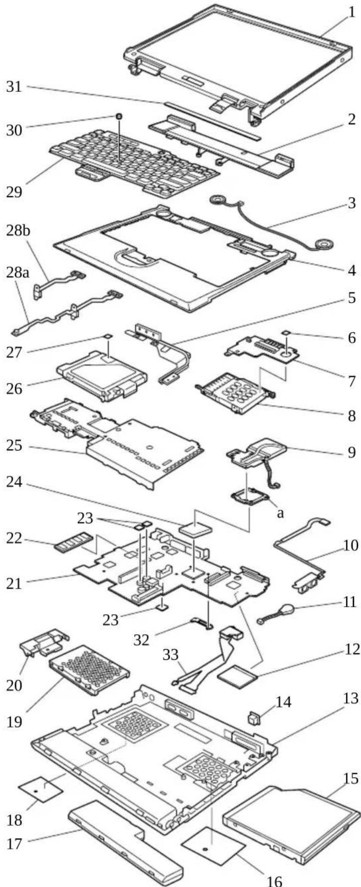
•Each FRU is available for all types/models, unless specific types or models are given.
•The FRUs marked with asterisk are CRUs (customer replacable units).
•The FRUs marked with OP are also available as optional FRUs.
| No. FRU P/N | ||
| a | See Miscellaneous parts on page 145. | |
| 1 | LCD unit (see LCD FRUs on page 136) | |
| 2 Hinge cover (for A20m/A20p) | ||
(continued)
Parts list
| No. FRU P/N | ||
| 4 Keyboard bezel for 12.1/14.1-in. LCD models | ||
(continued)
Parts list
| No. FRU P/N | ||
| 9 Fan assembly | ||
| 10 TV card (out only)2628-Fxx, Gxx, Sxx, Txx, Xxx2633-Gxx, Txx | 08K3259 | |
| TV card (in/out)2629-6xx, Hxx, Uxx | 10L1419 | |
| 11 Backup battery 02K6572 | ||
| 12 Mini PCI adapter | ||
(continued)
| No. FRU P/N | |
| 12 Mini PCI adapter | |
| Mini PCI modem card (Ambit) for A20m/p,A21m/p2628-11x, 12x, 21x, 22x, 31x, 32x, 41x,42x, 44x, 47x, 48x, 4Dx, 4Ex, 4Fx, 4Gx,4Hx, 4lx, Bxx except xxJ, xxK, xxA2628-1Ax, 1Cx, 3Ax, 3Cx, 4Ax, 4Cx, 4Lxexcept xxA, xxJ, xxK2628-Cxx, Dxx, Exx, Fxx, Gxx except xxA2628-3JC, 3KC2628-JAx, JCx except xxA2629-61x, 62x except xxA, xxJ, xxK2629-Hxx except xxA2633-41x, 42x except xxA, xxJ, xxK2633-Gxx except xxA | 08K3252 |
| Mini PCI modem card (Ambit) for A22m/p2628-x1x, x2x except xxJ, xxK2629-U1x, U2x except xxJ, xxK2633-x1x, x2x except xxJ, xxK | 08K3383 |
| Mini PCI modem card (M2) (IBM) for A20m/p2628-11A, 12A, 1AA, 1CA, 21A, 22A, 31A,32A, 3AA, 3CA, 41A, 42A, 44A, 47A, 48A,4AA, 4CA, 4LA, 4DA, 4EA, 4FA, 4GA,4HA, 4IA2629-61A, 62A2633-41A, 42A | 08K3429 |
| Mini PCI modem card (IBM CR) for A21m/p2628-xxA2629-xxA2633-xxA | 08K3338 |
| Mini PCI Ethernet card (Intel) 2.6 for A20m/p2628-xxJ, xxK except 43x, 45x2629-xxJ, xxK2633-41J, 41K, 42J, 42K | 10L1423 |
| Mini PCI Ethernet card (Intel) 3.0for A21m/p2628-xxJ, xxK2629-xxJ, xxK2633-xxJ, xxKfor A22m/p2628-x1J, x1K, x2J, x2K2629-U1J, U1K, U2J, x2K2633-x1J, x1K, x2J, x2K | 08K3348 |
(continued)
Parts list
| No. FRU P/N | ||
| 13 B | Base cover for A20m | |
| 2628-1xx, 2xx, 3xx, 4xx except xxK, xxT, 2628-Bxx | 04P3410 | |
| 2628-1xK, 2xK, 3xK, 4xK 04P3412 | ||
| 2628-1xT, 2xT, 3xT, 4xT 04P3411 | ||
| 2633-4xx except 4xK, 4xT 08K5901 | ||
| 2633-4xK 08K5904 | ||
| 2633-4xT 08K5902 | ||
| Base cover for A20p | ||
| 2629-6xx except 6xK, 6xT 08K5640 | ||
| 2629-6xK 08K5646 | ||
| 2629-6xT 08K5642 | ||
| Base cover for A21m | ||
| 2628-Dxx, Exx, Fxx, Gxx except xxK, xxT 04P3711 | ||
| 2628-Jxx except JxK, JxT 04P3712 | ||
| 2628-DxK, ExK, FxK, GxK 04P3719 | ||
| 2628-JxK 04P3720 | ||
| 2628-DxT, ExT, FxT, GxT 04P3715 | ||
| 2628-JxT 04P3716 | ||
| 2633-Gxx except GxK, GxT 04P3714 | ||
| 2633-GxK | 04P3722 | |
| 2633-GxT | 04P3718 | |
| Base cover for A21p | ||
| 2629-Hxx except HxK, HxT | 04P3713 | |
| 2629-HxK | 04P3721 | |
| 2629-HxT | 04P3717 | |
| Base cover for A22m | ||
| 2628-Pxx, Qxx, Rxx, Sxx, Txx except xxK, xxT | 26P9523 | |
| 2628-PxK, QxK, RxK, SxK | 26P9529 | |
| 2628-PxT, QxT, RxT, SxT | 26P9529 | |
| 2633-Txx except TxK, TxT 26P9525 | ||
| 2633-TxK | 26P9531 | |
| 2633-TxT 26P9528 | ||
| Base cover for A22p | ||
| 2629-Uxx except UxK, UxT | 26P9524 | |
| 2629-UxK | 26P9530 | |
| 2629-UxT | 26P9527 | |
(continued)
Parts list
| No. FRU P/N | ||
| 14 B | Blank cap RJ452628-x1x, x2x, x4x except xxJ, xxK2628-xAx,xCx except xxJ, xxK2628-3JC, 3KC, 4Lx2628-47G, 48G, 4DC, 4EC, 4FC, 4GC, 4HC, 4IC2628-xSx, xTx, xWx, xXx, x1J, x1K, x2J, x2K2629-x1x, x2x, x4x except xxJ, xxK2629-xAx,xCx except xxJ, xxK2629-USx, UTx, U1J, U1K, U2J, U2K2633-x1x, x2x, x4x except xxJ, xxK2633-xSx, xTx, xWx, xXx, x1J, x1K, x2J, x2K | 04P3975 |
| 15 Ultrabay 2000 device | ||
| CD-ROM drive (TOSHIBA) OP2628-1xx except 10U, 1ZU2628-2xx except 20U2628-3xx except 30U, 3JC, 3KC, 3ZU2628-4xx except 40U2628-Bxx2633-4xx | 05K9158 | |
| CD-ROM drive (LG) OP2628-1xx except 10U, 1ZU2628-2xx except 20U2628-3xx except 30U, 3JC, 3KC, 3ZU2628-4xx except 40U2628-Bxx2628-Cxx, Dxx, Fxx, Jxx2633-4xx | 05K9159 | |
| CD-ROM drive (LG) OP2628-Bxx2628-Pxx, Qxx, RAx2633-4xx | 08K9545 | |
| CD-ROM drive (TEAC) OP2628-Bxx2628-Cxx, Dxx, Fxx, Jxx2628-Pxx, Qxx, RAx2633-4xx | 27L3436 | |
| DVD-ROM drive (MKE) OP2628-4Ax, 4Cx, 4Ux, 4Vx, 3JC, 3KC2628-6xx except 6ZU2629-6xx except 60U | 05K9188 | |
| DVD-ROM drive (TOSHIBA) OP2628-4Ax, 4Cx, 4Ux, 4Vx, 3JC, 3KC2628-6xx except 6ZU2629-6xx except 60U | 05K9160 | |
(continued)
| No. FRU P/N | |
| 15 Ultrabay 2000 device | |
| DVD-ROM drive 8x (MKE)OP2628-Exx, Gxx2628-Rxx except RAx, Sxx, Txx, Xxx2629-Exx, Gxx, Hxx2629-UUx2633-Txx | 27L3447 |
| DVD-ROM drive (HITACHI)OP2628-Exx, Gxx2629-Exx, Gxx, Hxx2633-Gxx | 08K9513 |
| DVD-ROM drive (HITACHI)OP2628-Rxx except RAx, Sxx, Txx, Xxx2629-UUx2633-Txx | 27L4087 |
| CD-R/W drive (SONY)OP2629-Uxx except UUx | 08K9617 |
| for optional Ultrabay 2000 device, seeOptional-FRUs"onpage 14". | |
| 16 Cover, Mini PCI adapter slot 08K7294 | |
| 17 Battery pack (6 cell) | |
| Panasonic Li-Ion2628-1xx, 2xx, 3xx, 4xx, Bxx2628-Cxx, Dxx, Exx, Fxx, Gxx, Jxx except xxE, xxJ, xxK2628-Pxx, Qxx, Rxx, Sxx, Txx except xxE, xxJ2633-4xx, Txx2633-Cxx, Dxx, Exx, Fxx, Gxx, Jxx except xxE, xxJ, xxK | 02K6614* |
| SANYO Li-Ion2628-1xx, 2xx, 3xx, 4xx, Bxx2628-Cxx, Dxx, Exx, Fxx, Gxx, Jxx except xxE, xxJ, xxK2628-Pxx, Qxx, Rxx, Sxx, Txx except xxE, xxJ2633-4xx, Txx2633-Cxx, Dxx, Exx, Fxx, Gxx, Jxx except xxE, xxJ, xxK | 02K6618* |
| Panasonic Li-Ion (ECO)2628-xxE2628-DxJ, ExJ, FxJ, GxE, GxJ, IxJ2628-xxJ except CxJ, JxJ2633-DxJ, ExJ, FxJ, GxE, GxJ, IxJ | 02K6769* |
(continued)
| No. FRU P/N | ||
| 17 Battery pack (6 cell) | ||
(continued)
| No. FRU P/N | ||
| 19 H | Hard-disk drive (18.0 GB), STD OP2628-3JC, 3KC2629-6xx except 60U | 27L4073 |
| Hard-disk drive (20.0 GB), STD OP2628-Qxx, Rxx, Sxx, Xxx, T7x, T8x, TUx, TVx2629-6Ax, 6Cx, 6Ux, 6Vx | 27L4075 | |
| Hard-disk drive (20.0 GB), STD OP2628-Fxx, Gxx, Jxx2633-Gxx | 27L3427 | |
| Hard-disk drive (20.0 GB), HITACHI OP2628-Fxx, Gxx, Jxx2628-Qxx, Rxx, Sxx, Xxx, T7x, T8x, TUx, TVx2633-Gxx | 08K9533 | |
| Hard-disk drive (30.0 GB), STD OP2628-Txx except T7x, 8x, TUx, TVx2633-Txx | 08K9564 | |
| Hard-disk drive (30.0 GB), HITACHI OP2628-Txx except T7x, 8x, TUx, TVx2633-Txx | 08K9692 | |
| Hard-disk drive (32.0 GB), STD OP2629-Hxx, Uxx | 08K9509 | |
| 20 C | Cover, hard-disk drive for 12.1/14.1-in. models2628-1xx, 2xx, 4xx, Bxx, Cxx, Dxx, Exx,Gxx, Qxx, Rxx, Txx2633-4xx, Gxx, Txx | 08K5675 |
| Cover, hard-disk drive for 15.0-in. models2628-3xx, Fxx, Jxx, Pxx, Sxx2629-6xx, Fxx, Hxx, Jxx, Uxx | 08K5676 | |
| — | Asset ID RF adapter (see Optional FRUs" on page 14") | |
| 21 S | System board for A20 | |
| Video memory 4 MB2628-1xx, 2xx, Bxx | 08K3314 | |
| Video memory 8 MB2628-3xx except 3JC, 3KC | 08K3315 | |
| Video memory 8 MB2628-4xx, 3JC, 3KC, 2633-4xx | 08K3316 | |
| Video memory 16 MB2629-6xx | 08K3317 | |
| System board for A21 | ||
| Video memory 4 MB2628-Cxx, Jxx | 08K3262 | |
| Video memory 4 MB2628-Dxx, Exx | 08K3263 | |
| Video memory 4 MB2628-Jxx | 26P7975 | |
(continued)
Parts list
| No. FRU P/N | ||
| 21 System board for A21 | ||
(continued)
| No. | FRU P/N | |
| 24 | CPU, Celeron 500 MHz2628-1xx, 3xx, 47x, 48x | 08K3149 |
| CPU, Celeron 550 MHz2628-1Ax, 1Cx, 1Ux, 1Vx, 1ZU, 3Ax, 3Cx, 3Ux, 3Vx, 3ZU | 08K3211 | |
| CPU, Pentium III 500 MHz2628-2xx, Bxx | 10L1415 | |
| CPU, Pentium III 600 MHz with SpeedStep technology2628-4Ax, 4Cx, 4Ux, 4Vx, 4ZU | 08K3213 | |
| CPU, Pentium III 650 MHz with SpeedStep technology2628-4Dx, 4Ex, 4Fx, 4Gx | 10L1405 | |
| CPU, Pentium III 650 MHz with SpeedStep technology2628-Hxx | 12P3450 | |
| CPU, Pentium III 700 MHz with SpeedStep technology2628-4xx except 47x, 48x, 4Dx, 4Ex, 4Fx, 4Gx2628-3JC, 3KC, 4Lx2629-6xx2633-4xx | 10L1417 | |
| CPU, Pentium III 750 MHz with SpeedStep technology2628-Fxx2629-6Ax, 6Cx, 6Ux, 6Vx, 6ZU | 08K3191 | |
| CPU, Pentium III 800 MHz with SpeedStep technology2628-Gxx, Pxx, Qxx2633-Gxx | 12P3448 | |
| CPU, Pentium III 850 MHz with SpeedStep technology2628-Rxx, Xxx | 12P3450 | |
| CPU, Pentium III 900 MHz with SpeedStep technology2628-Sxx | 26P8126 | |
| CPU, Pentium III 900 MHz with SpeedStep technology2629-Yxx | 08K3346 | |
| CPU, Pentium III 1 GHz with SpeedStep technology2628-Txx2629-Uxx2633-Txx | 08K3392 | |
| 25 | Upper shield assembly, front 08K7286 | |
| 26 | Diskette drive (TEAC) 05K9157 | |
| Diskette drive (SONY) 08K9552 |
(continued)
| No. FRU P/N | ||
| 27 Spacer, diskette drive for 2629 04P3225 | ||
| 28a Microphone/speaker cable for A20m/A20p,A21m/A21p2628-1xx, 2xx, 3xx, 4xx, Bxx, Dxx, Exx,Fxx, Gxx2629-6xx, Dxx, Fxx, Gxx, Hxx2633-4xx, Gxx | 27L0484 | |
| 28b Speaker cable for A22m/A22p2628-Cxx, Jxx, Pxx, Qxx, Rxx, Sxx, Txx2629-Uxx2633-Txx | 27L0601 | |
| 29 | Keyboard* (see Keyboard on page 140) | |
| 30 P | Pointing stick cap for A20, 21 84G6536* | |
| Pointing stick cap for A22 26P9212* | ||
| 31 Clear sheet LED icon for A22 08K7304 | ||
| 32 Fan duct for A222628-Sxx, Txx, 2629-Uxx, 2633-Txx | 26P9208 | |
| 33 RJ45/11 connector assembly for A22 27L0645 | ||
| — Telephone cable 27L0603* | ||
| — Video cable2628-Fxx, Gxx2629-6xx, Fxx, Gxx, Hxx, Uxx2633-Gxx | 27L0531 | |
| — | AC adapter (see AC adapter on page 136.) | |
| — | Recovery CD (see Recovery CDs on page 14.) | |
AC adapter
All of the AC adapters listed below are CRUs (customer replaceable units.)
| FRU P/N | |
| AC adapter (72 W), 2-pin (ASTEC) models xxE, xxF, xxJ, xxP, xxS, xxU, xxX | 02K6669 |
| AC adapter (72 W), 2-pin (DELTA) models xxE, xxF, xxJ, xxP, xxS, xxU, xxX | 02K6673 |
| AC adapter (72 W), 2-pin (SANKEN) models xxE, xxF, xxJ, xxP, xxS, xxU, xxX | 02K6677 |
| AC adapter (72 W), 3-pin (ASTEC) models xxC, xxG, xxH, xxK, xxT, xxY | 02K6666 |
| AC adapter (72 W), 3-pin (DELTA) models xxC, xxG, xxH, xxK, xxT, xxY | 02K6670 |
| AC adapter (72 W), 3-pin (SANKEN) models xxC, xxG, xxH, xxK, xxT, xxY | 02K6674 |
LCD FRUs
12.1-in. SVGA TFT
Following FRUs are available for MT2628-1xx, 2xx, Bxx, Cxx, Dxx, Qxx.
| FRU P/N | |
| LCD cover assembly | |
| 2628-1xx, 2xx, Bxx, Cxx, Dxx except xxK 08K5655 | |
| 2628-1xK, 2xK2628-CxK, DxK | 08K5659 |
| 2628-Qxx except QxK (with heatpipe) 08K7288 | |
| 2628-QxK (with heatpipe) 08K7289 | |
| LCD cable 12.1 27L0485 | |
| LCD panel 12.1 SVGA (SANYO) 05K9577 | |
| Hinges 12.1 08K5664 | |
| Inverter card 12.1/14.1/15.02628-1xx, 2xx, Bxx | 08K3120 |
| Inverter card 12.1 (large)2628-Cxx, Dxx, Qxx | 08K3325 |
14.1-in. XGA TFT
Following FRUs are available for MT2628-4xx, Exx, Gxx, Txx, Xxx, MT2633-4xx, Gxx, Txx.
| FRU P/N | |
| LCD cover assembly 14.1 XGA | |
| 2628-4xx, Exx except xxK2633-4xx except 4xK | 08K5656 |
| 2628-4xK, ExK2633-4xK | 08K5660 |
| 2628-Txx except TxK2628-Xxx2633-Txx except TxK2633-Xxx | 12P4215 |
| 2628-TxK2633-TxK | 08K7291 |
| with heatpipe2628-Gxx except GxK2633-Gxx except GxK | 04P3485 |
| with heatpipe2628-GxK2633-GxK | 08K7111 |
| LCD cable 14.12628-4xx, Exx, Gxx, Txx, Xxx2633-4xx, Gxx,Txx | 27L0486 |
| LCD panel 14.1 XGA (DBU)2628-4xx, Exx, Gxx, Txx, Xxx2633-4xx, Gxx, Txx | 05K9578 |
| LCD panel 14.1 XGA (SAMSUNG)2628-4xx, Exx, Gxx, Txx, Xxx2633-4xx, Gxx, Txx | 05K9588 |
| Hinges 14.12628-4xx, Exx, Gxx, Txx, Xxx2633-4xx, Gxx, Txx | 08K5665 |
| Inverter card 12.1/14.1/15.02628-4xx2633-4xx | 08K3120 |
| Inverter card 12.1/14.1/15.02628-Exx | 12P3051 |
| Inverter card (slim)2628-Gxx, Txx2633-Gxx, Txx | 12P3053 |
15.0-in. XGA TFT (LG)
Following FRUs are available for MT2628-3xx, Jxx, Pxx, Rxx.
| FRU P/N | |
| LCD cover assembly 15.0 XGA | |
| 2628-3xx, Jxx except xxK (without heatpipe) 26P9403 | |
| 2628-3xK, JxK (without heatpipe) 26P9404 | |
| 2628-Pxx, Rxx except xxK(with heatpipe) 26P9405 | |
| 2628-PxK, RxK(with heatpipe) 26P9406 | |
| LCD cable 15.0 XGA (LG)2628-3xx, Jxx, Pxx, Rxx | 27L0578 |
| LCD panel 15.0 XGA (LG)2628-3xx, Jxx, Pxx, Rxx | 05K9647 |
| Hinges 15.0 (LG) (for 2628-3xx) 04P3051 | |
| Hinges 15.02628-3xx, Jxx, Pxx, Rxx | 04P3488 |
| Inverter card 12.1/14.1/15.0 (for 2628-3xx) 08K3120 | |
| Inverter card 15.0 XGA (for 2628-Jxx) 08K3326 | |
| Inverter card (slim) (for 2628-Pxx, Rxx) 12P3053 | |
| Misc kit for 15.0 XGA (LG) for 2628-Jxx (see “Miscellaneous parts” on page 145.) | |
15.0-in. XGA TFT (SAMSUNG)
Following FRUs are available for MT2628-3xx, Fxx, Jxx, Pxx, Rxx.
| FRU P/N | |
| LCD cover assembly 15.0 XGA | |
| 2628-3xx, Jxx except xxK (without heatpipe) 26P9403 | |
| 2628-3xK, JxK (without heatpipe) 26P9404 | |
| 2628-Fxx, Pxx, Rxx except xxK(with heatpipe) 26P9405 | |
| 2628-FxK, PxK, RxK(with heatpipe) 26P9406 | |
| LCD cable 15.0 XGA (SAMSUNG)2628-3xx, Fxx, Jxx, Pxx, Rxx | 27L0487 |
| LCD panel 15.0 XGA (SAMSUNG)2628-3xx, Fxx, Jxx, Pxx, Rxx | 05K9580 |
| Hinges 15.02628-3xx, Fxx, Jxx, Pxx, Rxx, Sxx | 04P3488 |
| Inverter 12.1/14.1/15.0 (for 2628-3xx) 08K3120 | |
| Inverter card 15.0 XGA (for 2628-Jxx) 08K3326 | |
| Inverter card (slim) (for 2628-Gxx, Pxx, Rxx, Sxx) 12P3053 | |
15.0-in. SXGA+ TFT
Following FRUs are available for MT2628-Sxx and 2629-6xx.
| FRU P/N | |
| LCD cover assembly | |
| 2628-Sxx except SxK (with heatpipe LM) 26P9210 | |
| 2628-SxK (with heatpipe LM) 26P9211 | |
| 2629-6xx except 6xK 26P9532 | |
| 2629-6xK 26P9533 | |
| LCD cable 15.0 SXGA+ (for 2629-6xx) 27L0488 | |
| LCD cable 15.0 SXGA+2628-Sxx2629-6xx | 27L0662 |
| LCD panel 15.0 SXGA+ (DBU)2628-Sxx2629-6xx | 05K9581 |
| Hinges 15.02628-Fxx, Jxx, Sxx2629-6xx | 04P3488 |
| Inverter card (slim) (for 2629-Fxx, Gxx) 12P3053 | |
15.0-in. UXGA TFT
Following FRUs are available for MT2629-Hxx, Uxx, Yxx.
| FRU P/N | |
| LCD cover assembly | |
| 2629-6xx, Hxx, Uxx except xxK 26P9532 | |
| 2629-6xK, HxK, UxK 26P9533 | |
| LCD cable 15.0 UXGA (for 2629-Hxx, Uxx) 27L0664 | |
| LCD panel 15.0 UXGA (DBU) (for 2629-Hxx, Uxx) 05K9835 | |
| LCD panel 15.0 UXGA (LG) (for 2629-Hxx, Uxx) | 05K9693 |
| Hinges 15.0 (for 2629-Hxx, Uxx) | 04P3488 |
| Inverter card (slim) (for 2629-Hxx, Uxx) 12P3053 | |
Keyboard
All of the keyboards listed below are CRUs (customer replaceable units.)
| Language P/N | |||
| A20m/p A | 21m/p A22 | m/p | |
| Arabic 02K5051 02K5476 | |||
| Belgian 02K5045 02K5470 | |||
| Canadian French 02K5035 02K5456 | |||
| Chinese, traditional 02K5057 02K5459 | |||
| Czech 02K5055 02K5480 | |||
| Danish 02K5042 02K5467 | |||
| Dutch 02K5039 02K5464 | |||
| English, U.K. 02K5036 02K5461 | |||
| English, U.S. 02K5034 02K5455 | |||
| French, European 02K5038 02K5463 | |||
| German 02K5037 02K5462 | |||
| Greek 02K5048 02K5473 | |||
| Hebrew | 02K5049 | 02K5474 | |
| Hungarian | 02K5054 | 02K5479 | |
| Italian | 02K5043 | 02K5468 | |
| Japanese | 02K5056 | 02K5458 | |
| Korean | 02K5058 | 02K5460 | |
| Norwegian | 02K5041 | 02K5466 | |
| Polish 02K5150 02K5481 | |||
| Portuguese | 02K5047 | 02K5472 | |
| Russian 02K5052 02K5477 | |||
| Slovak | 02K5053 | 02K5478 | |
| Slovenian | 02K5151 | 02K5482 | |
| Spanish, European | 02K5044 | 02K5469 | |
| Spanish, Latin American | 02K5059 | 02K5457 | |
| Swedish or Finnish | 02K5040 | 02K5465 | |
| Swiss 02K5046 02K5471 | |||
| Thai | — | — | 02K5759 |
| Turkish | 02K5050 | 02K5475 | |
Recovery CDs
For Windows 98 (A22m)
| Language P/N | |
| Arabic 23P8930 | |
| Chinese, Simplified 27P2266 | |
| Chinese, Traditional 27P2261 | |
| Czech 23P8931 | |
| Danish 23P8897 | |
| Dutch 23P8904 | |
| English, U.S. 23P8892 | |
| English, U.K. 23P8893 | |
| Finnish 23P8903 | |
| French, Canadian 23P8894 | |
| French, European 23P8898 | |
| German 23P8899 | |
| Greek 23P8935 | |
| Hebrew | 23P8932 |
| Hungarian | 23P8936 |
| Italian | 23P8902 |
| Japanese | 46P4403 |
| Norwegian | 23P8905 |
| Polish 23P8933 | |
| Portuguese | 23P8896 |
| Spanish, European | 23P8900 |
| Spanish, Latin American | 23P8895 |
| Slovenian | 23P8938 |
| Slovak | 23P8939 |
| Swedish | 23P8901 |
| Thai | 23P8940 |
| Turkish 23P8934 | |
| Russian 23P8937 |
For Windows 98 (A22p)
| Language P/N | |
| Arabic 23P9062 | |
| Arabic (modem enabled) 14P9553 | |
| Chinese, Simplified 27P2256 | |
| Chinese, Traditional 27P2251 | |
| Czech 23P9063 | |
| Danish 23P9029 | |
| Dutch 23P9036 | |
| English, U.S. 14P9569 | |
| English, U.K. 14P9582 | |
| Finnish 23P9035 | |
| French, Canadian 23P9026 | |
| French, European 23P9030 | |
| German 14P9586 | |
| Greek 23P9067 | |
| Hebrew | 23P9064 |
| Hungarian | 23P9068 |
| Italian | 23P9034 |
| Japanese | 46P4400 |
| Norwegian | 23P9037 |
| Polish 23P9065 | |
| Portuguese | 23P9028 |
| Spanish, European | 23P9032 |
| Spanish, Latin American | 23P9027 |
| Slovenian | 23P9070 |
| Slovak | 23P9071 |
| Swedish | 14P9590 |
| Thai | 23P9072 |
| Turkish 23P9066 | |
| Russian 23P9069 |
For Windows 2000 (A22m)
| Language P/N | |
| Chinese, Simplified 27P2268 | |
| Chinese, Traditional 27P2263 |
For Windows 2000 (A22p)
| Language P/N | |
| Chinese, Simplified 27P2258 | |
| Chinese, Traditional 27P2253 |
For Windows 2000/Windows NT (A22m)
| Language P/N | |
| Arabic 23P9002 | |
| Czech 23P9003 | |
| Danish 23P8957 | |
| Dutch 23P8964 | |
| English, U.S. 23P8952 | |
| English, U.K. 23P8953 | |
| Finnish 23P8963 | |
| French, Canadian 23P8954 | |
| French, European 23P8958 | |
| German 23P8959 | |
| Greek 23P9007 | |
| Hebrew 23P9004 | |
| Hungarian | 23P9008 |
| Italian | 23P8962 |
| Japanese | 27P1871 |
| Norwegian | 23P8965 |
| Polish 23P9005 | |
| Portuguese | 23P8956 |
| Spanish, European | 23P8960 |
| Spanish, Latin American | 23P8955 |
| Slovenian | 23P9010 |
| Slovak | 23P9011 |
| Swedish | 23P8961 |
| Thai | 23P9012 |
| Turkish 23P9006 | |
| Russian 23P9009 |
For Windows 2000/Windows NT (A22p)
| Language P/N | |
| Arabic 23P9134 | |
| Arabic (modem enabled) 14P9558 | |
| Czech 23P9135 | |
| Danish 23P9089 | |
| Dutch 23P9096 | |
| English, U.S. 14P9572 | |
| English, U.K. 14P9594 | |
| Finnish 23P9095 | |
| French, Canadian 23P9086 | |
| French, European 23P9090 | |
| German 23P9091 | |
| Greek 23P9139 | |
| Hebrew 23P9136 | |
| Hungarian 23P9140 | |
| Italian 23P9094 | |
| Japanese | 46P4400 |
| Norwegian | 23P9097 |
| Polish 23P9137 | |
| Portuguese | 23P9088 |
| Spanish, European | 23P9092 |
| Spanish, Latin American | 23P9087 |
| Slovenian | 23P9142 |
| Slovak | 23P9143 |
| Swedish | 23P9093 |
| Thai | 23P9144 |
| Turkish 23P9138 | |
| Russian 23P9141 |
Miscellaneous parts
| FRU P/N | |
| Screw kit (including nylon-coated screws):•M2 x 3.6 mm, flat head (3)•M2 x 5.1 mm, flat head (5)•M2 x 5.7 mm, flat head (5)•M2 x 16 mm, bind head (3)•M2.5 x 4.8 mm, flat head (42)•M2.5 x 5.5 mm, flat head (2)•M2.5 x 15 mm, flat head (15)•M2.6 x 2.8 mm, bind head (7)•M3 x 2.8 mm, small head (5)•Coin screw (1)•Security screw (1)•Screw caps (14) | 04P3973 |
| Base miscellaneous parts:•Lens, IR•Lens, Ultrabay 2000 LES•Lock, battery•Spring, battery lock•Lid, docking FR•Lid, docking RR•Spring, lid docking•Rubber foot•Sponge•Sponge, shield lower•Sponge, small•Blank cap, battery•Screw caps•Cu tape | 08K5647 |
| System miscellaneous parts (for A20m/p, A21m/p):•Door, PC card slots•Door, PC card 1 slot•Spring, PC card slots•Lens, LED hinge•Blank cap, TV connector•Eject knob, Ultrabay 2000•Lock lever, Ultrabay 2000•Spring, Ultrabay 2000•Insulator, hard-disk drive•Insulator, keyboard CRU•Mini PCI guide•(a) Stiffner, CPU socket•Screw caps | 04P3966 |
(continued)
| FRU P/N | |
| System miscellaneous parts (for A22m/p):•Keyboard stopper•Door, PC card slots•Door, PC card 1 slot•Spring, PC card slots door•Lens, LED hinge•Blank cap, TV connector•Eject knob, Ultrabay 2000•Lock lever, Ultrabay 2000•Spring 1, Ultrabay 2000•Spring 2, Ultrabay 2000•Insulator, hard-disk drive•Insulator, keyboard CRU•Mini PCI guide•(a) Stiffner, CPU socket - upper•Screw caps | 26P9209 |
| Miscellaneous parts, for system board (for A20m/p, A22m/p):•I/O bracket (right/left)•Guide, keyboard connector•Hex stud•I/O bracket spacer•FDD sponge•Docking hole cap•Flat head screw (M2.5 x 4.8)•Screw caps | 26P9335 |
| Miscellaneous parts, for diskette drive:•Bezel•Bezel without icon•Bracket•Flexible cable•Screw caps | 26P9336 |
| Miscellaneous parts, for LCD:•Latch (right/left)•Spring•Spacer (for 15.0-in.)•Blank cap, UltraPort•Screw caps | 04P3968 |
| Miscellaneous kit for LCD 15.0-in. LG•Latch (RH 15.0 LG)•Latch (LH 15.0 LG)•Spring (15.0 LG)•Spacer (for 15.0-in.)•Screw caps | 04P3050 |
Optional FRUs
| FRU P/N | |
| Ultrabay 2000 SuperDisk drive 05K9235 | |
| ZIP-250 00N8254 | |
| Multiple battery charger 02K6642 | |
| Ultrabay 2000 2nd HDD adapter 08K6067 | |
| Ultrabay 2000 battery 02K6645 | |
| UltraPort camera for MT2629 02K5153 | |
| IBM tripod 08K6449 | |
| UltraPort adapter and connector cover 08K6105 | |
| USB cable attachment 08K6108 | |
| USB cable 27L0542 | |
| ThinkPad Dock 08N1546 | |
| PCI cover 05K6246 | |
| ThinkPad Dock with extension plate 08N1537 | |
| PCI cover with foot | 08K7317 |
| Top cover and screw kit for ThinkPad Dock | 12P4143 |
| ThinkPad Port Replicator | 08N1536 |
| Asset ID RF adapter | 08K6065 |
Common parts list
Tools
| Tools P/N | |
| Triconnector wrap plug 72X8546 | |
| PC test card 35G4703 | |
| Audio wrap cable 66G5180 | |
| USB parallel test cable 05K2580 | |
| Screwdriver kit 95F3598 | |
| Torque screwdriver 05K4695 | |
| 5 mm socket wrench 05K4694 | |
| Screwdriver 27L8126 | |
| ThinkPad hardware maintenance diskette version 1.62Note: Download the file from the Web site. | — |
Power cords (system)
IBM power cords for a specific country are usually available only in that region:
For 2-pin power cords:
| Region P/N | |
| Canada, United States of America | 13H5264 |
| Japan | 13H5273 |
| Argentina | 36L8870 |
For 3-pin power cords:
| Region P/N | |
| Australia, New Zealand | 76H3514 |
| Taiwan, Thailand | 76H3516 |
| Italy | 76H3530 |
| Denmark | 76H3520 |
| U.K., China (Hong Kong S.A.R.) | 76H3524 |
| European countries | 76H3518 |
| India, South Africa | 76H3522 |
| Israel | 76H3532 |
| Korea | 76H3535 |
| China (P.R.C.) (other than Hong Kong) | 02K0539 |
| Switzerland | 76H3528 |
Power cords (docking station)
IBM power cords for a specific country are usually available only in that region:
For 3-pin power cords:
| Region P/N | |
| Argentina 36L8868 | |
| Australia, New Zealand 75H8988 | |
| Canada, Thailand, United States of America 75H8989 | |
| Denmark 75H8992 | |
| European countries 75H8990 | |
| India, South Africa 75H8993 | |
| Israel 75H8999 | |
| Italy 75H8998 | |
| Japan 75H8996 | |
| Korea 76H3536 | |
| People's Republic of China (other than Hong Kong) 02K0540 | |
| Switzerland 75H8997 | |
| United Kingdom | 75H8994 |
Notices
References in this publication to IBM products, programs, or services do not imply that IBM intends to make these available in all countries in which IBM operates. Any reference to an IBM product, program, or service is not intended to state or imply that only that IBM product, program, or service may be used. Any functionally equivalent product, program, or service that does not infringe any of the intellectual property rights of IBM may be used instead of the IBM product, program, or service. The evaluation and verification of operation in conjunction with other products, except those expressly designated by IBM, are the responsibility of the user.
IBM may have patents or pending patent applications covering subject matter in this document. The furnishing of this document does not give you any license to these patents. You can send license inquiries, in writing, to the IBM Director of Licensing, IBM Corporation, 500 Columbus Avenue, Thornwood, NY 10594, U.S.A.
Trademarks
The following terms are trademarks of the IBM Corporation in the United States or other countries or both:
Asset ID
IBM
OS/2
ThinkLight
ThinkPad
TrackPoint
Ultrabay
UltraPort
Microsoft, Windows, Windows NT, and the Windows logo are trademarks of Microsoft Corporation in the United States and/or other countries.
Pentium is trademark of Intel Corporation in the United States and/or other countries. (For a complete list of Intel trademarks, see the legal information on http://www.intel.com/)
Other company, product, or service names may be the trademarks or service marks of others.
Notices
Part Number: 23P0896
- Note
- Second Edition (October 2001)
- The following paragraph does not apply to the United Kingdom or any country where such provisions are inconsistent with local law:
- © Copyright International Business Machines Corporation 2001. All rights reserved.
- About this manual
- Important
- Contents
- Introduction
- Important service information
- Strategy for replacing FRUs
- Before replacing parts
- Strategy for replacing a hard-disk drive
- How to use error messages
- Diskette compatibility matrix
- Safety notices: multilingual translations
- Safety notice 1
- General safety
- Electrical safety
- Safety inspection guide
- Checklist:
- Handling electrostatic discharge-sensitive devices
- Notes
- Grounding requirements
- Laser compliance statement
- CAUTION:
- DANGER
- General descriptions
- Read this first
- Important notes
- What to do first
- Note for warranty:
- The following are not covered under warranty:
- The following symptoms might indicate damage caused by nonwarranted activities:
- Related service information
- Service web site
- Product recovery program
- Restoring the pre-installed software:
- Creating the service partition:
- To create the Service Partition (SP):
- Install preloaded system from CD:
- To create a recovery repair diskette
- To use the recovery repair diskette:
- Passwords
- Power-on password:
- Hard-disk password:
- Attention
- Supervisor password:
- How to remove the power-on password
- How to remove the hard-disk password
- Power management
- Screen blank mode
- Standby mode
- Note for the APM operating system:
- Hibernation mode
- Note for Windows NT
- Note for OS/2
- Checkout guide
- Testing the computer
- Detecting system information with PC-Doctor
- Hardware Info
- Utility
- Power system checkout
- Checking the ac adapter
- Checking operational charging
- Checking the battery pack
- Checking the backup battery
- ThinkPad A20m/p, A21m/p and A22m/p
- Product overview
- Specifications
- Status indicators
- FRU tests
- Fn key combinations
- Symptom-to-FRU index
- LCD-related symptoms
- Intermittent problems
- Undetermined problems
- FRU replacement notices
- Screw notices
- Retaining serial numbers
- Restoring the serial number of the system unit
- Retaining the UUID
- Removing and replacing a FRU
- Battery pack
- DIMM
- Mini PCI adapter
- For A20m/p, A21m/p series
- For A22m/p series
- Backup battery
- Hard-disk drive or RF ID adapter
- Ultrabay 2000 device
- Keyboard
- When installing: When installing the keyboard, do as follows:
- Keyboard CRU insulator
- Hinge cover and clear sheet icon
- Keyboard bezel and speaker
- Microphone and speaker cable
- For A20m/p and A21m/p series (microphone and speaker cable)
- Sub card
- PC Card slot assembly
- Fan assembly
- Installation notice for A21m/p and A22m/p series
- Diskette drive
- Notes:
- Upper shield
- TV card
- CPU socket and CPU
- System board and RJ45/11 connector assembly
- Thermal rubbers location
- LCD assembly
- Front bezel
- 12.1-in. panel
- Inverter card
- 14.1-in. and 15.0-in. panels
- LCD panel
- ThinkPad Dock PCI cover
- Before replacing the PCI cover:
- ThinkPad Dock top cover
- Locations
- Front view
- Rear view
- Bottom view
- Parts list
- A series model matrix
- Overall
- AC adapter
- LCD FRUs
- 12.1-in. SVGA TFT
- 14.1-in. XGA TFT
- 15.0-in. XGA TFT (LG)
- 15.0-in. XGA TFT (SAMSUNG)
- 15.0-in. SXGA+ TFT
- 15.0-in. UXGA TFT
- Keyboard
- Recovery CDs
- Common parts list
- Power cords (system)
- Power cords (docking station)
- Notices
- Trademarks
Brand : IBM
Model : ThinkPad A20
Category : Laptop