
DY365 - Switch ABB - Free user manual and instructions
Find the device manual for free DY365 ABB in PDF.


| Product Type | Astronomical digital time switch with bus connection |
| Brand | ABB |
| Model | DY365 |
| Power Supply | 230 VAC (-15%/+10%), 50/60 Hz, 7 VA (2.6 W) |
| Channels | 8 (2 onboard relays + up to 6 via remote actuators DY365 4CE/DY365 2CE) |
| Relay Load (per channel) | 16 A / 250 V AC (monostable change-over) |
| Program Capacity | 450 programs (900 events), divisible over 8 channels |
| Display | LCD with backlight (active with AC power) |
| Bluetooth | BLE 4.2, frequency band 2400-2483.5 MHz, max power 4 dBm |
| Backup Battery | Lithium 3 V, CR14250 type (replaceable) |
| Operating Temperature | -20°C to +50°C |
| Humidity | 20% to 90% non-condensing |
| Protection Degree | IP20 |
| Dimensions (W x H x D) | 72 x 88 x 65 mm (4 DIN modules) |
| Weight | Approx. 200 g |
| Memory Backup | Settings retained via battery for up to 60 seconds during battery replacement |
| Accessories | GPS module (DY GPS), DCF77 module, remote actuator modules (DY365 4CE, DY365 2CE) |
| Standards Compliance | EU Directive 2014/53/EU (RED), EN 60730-2-7, ETSI EN 301 489, ETSI EN 300 328 |
| Installation | By qualified personnel only; overcurrent protection required upstream |
| Maintenance | Replace battery when icon appears; clean with dry cloth |
Frequently Asked Questions - DY365 ABB
User questions about DY365 ABB
0 question about this device. Answer the ones you know or ask your own.
Ask a new question about this device
Download the instructions for your Switch in PDF format for free! Find your manual DY365 - ABB and take your electronic device back in hand. On this page are published all the documents necessary for the use of your device. DY365 by ABB.
USER MANUAL DY365 ABB
DIGITAL YEARLY TIME/ASTRONOMICAL SWITCH
DY365
User Manual

ABB
Index
■ Technical features page 3
■ Safety warnings page 4
■ Dimensions page 4
■ Wiring diagrams page 5
■ Display and keyboard description page 6
■ Initial operation page 7
■ Start page (or main) page 8
■ Menu description page 11
■ Settings menu page 12
Language setting menu page 13
Date setting menu page 14
Time setting menu page 15
Daylight saving time (DST)/winter time (CET)
change setting menu page 16
Astronomical coordinates setting menu page 18
Random switchings setting menu page 20
Cycle switchings setting menu page 21
Protection PIN setting menu
■ Manual operation menu
Program menu
Program menu: new
Program menu: new daily timed
Program menu: new weekly timed
Program menu: new yearly timed (or monthly)
Program menu: new holiday timed
page 20
page 21
page 22
page 23 page 26
page 31
page 32
page 33
page 34
page 36
Program menu: new astro night page 38
Program menu: new astro daily page 42
Program menu: new astro weekly page 43 Program menu: new astro yearly (or monthly) page 44
Program menu: new astro holiday page 46
Program menu: check page 48
Program menu: modify page 50
Program menu: copy page 52
Program menu: delete page 53
Bluetooth
Bus menu
Simple network configuration (one DY365, one or more remote actuators) page 58
Complex network configuration (several
DY365, one or more remote actuators) page 58 Connection test page 59
Programs copy on the bus page 60
Reception programs on the bus page 61
■ SYNC menu page 62
■ Hour couter menu page 64
■ Reset menu page 66
■ Firmware menu page 68
■ Error signals page 69
■ Battery management page 70
■ Reference standards page 70
USER MANUAL
DY365 is an electronic digital time switch for the management over time of the electrical devices. It allows time programming (periodicity: daily, weekly or annual) or astronomical programming. DY365 has two on-board relays but it's able to control up to eight different channels (relay); the other six channels are realized by remote actuators available as accessories: DY365 4CE (4 relays) or DY365 2CE (2 relays), connected to the DY365 via BUS. Each channel can be associated with a different programming (time or astronomical). DY365 also offers the possibility to connect via BUS a GPS module, DY GPS (available as an accessory), that captures the time and the position through the satellite system, ensuring high accuracy over time or DY DCF77 (available as an accessory), that captures the time ensuring high accuracy over time. The backup battery keeps the settings even in case of power failure and can be replaced through the cover (sealable). DY365 time switch has a Bluetooth interface that allows it to be coupled with mobile devices (smartphone or tablet). Thanks to the free app that can be downloaded from the AppStore and Google Play stores, it is possible to program and make settings directly on your smartphone, and then transfer all the data to the time switch.
Code Model Description
| 2CSM221201R1000 | DY365 | Astronomical time switch with bus for connecting GPS modules and remote actuators |
| 2CSM250411R1000 | DY GPS | GPS module for receiving time and position from satellites |
| 2CSM250421R1000 | DY DCF77 | Time module for receiving time |
| 2CSM221181R1000 | DY365 4CE | Remote actuator module with 4 auxiliary relays of 8A / 250V |
| 2CSM221191R1000 | DY365 2CE | Remote actuator module with 2 auxiliary relays of 8A / 250V |


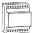

DY GPS / DY DCF77 DY365 4CE DY365 2CEDY365
-2-
User manual DY365
TECHNICAL FEATURES
• Power supply: 230 Vac (-15% ÷ +10%) 50/60 Hz
• Power consumption: 7 VA (2.6W)
• Lithium backup battery: 3V, CR14250 type (replaceable)
• 8 available channels*
- Terminals for:
- device power supply (terminals 1-2)
- auxiliary power supply output of 12V dc ±10%, 80mA, 1W (compatible with DY GPS or DY DCF77 power supply) (terminals 6-7)
- communication bus for the connection of DY365 4CE, DY365 2CE, DY GPS or DY DCF77 additional modules (terminals 8-9)
- monostable change-over relay 1 with maximum switchable load of 16A / 250V (terminals 10-11-12)
- monostable change-over relay 2 with maximum switchable load of 16A / 250V (terminals 16-17-18)
- Terminal block for cables with maximum cables section of 2.5 mm ^4
• Display LCD with backlight (active with AC power supply)
• Storable programs: 450 (900 events) (divisible on 8 channels)
- Actions type: 1B
- Bluetooth BLE 4.2 communication interface (active with mains power supply)
- Operating frequency band: 2400-2483.5 MHz
• Maximum transmitted radiofrequency power: 4 dBm
• Operating temperature: -20 ÷ +50 °C
- Operating humidity: 20 ÷ 90% non condensing
• Storage temperature: -25 ÷ +70 °C
- Container: 4 DIN modules
• Protection degree: IP20
- Insulation: reinforced between accessible parts (front) and all the other terminals
* The 8 channels are realized physically by as many relays. The channels 1 and 2 are realized by the relays mounted on the DY365; the other 6 channels are realized through the connection via bus of DY365 4CE / DY365 2CE additional modules.
SAFETY WARNINGS
■ During product installation and operation it is necessary to observe the following instructions:
1) The instrument must be installed by a qualified person, strictly in observance of the connection diagrams shown in this manual.
2) After installation inaccessibility to the terminals without using dedicated tools must be guaranteed.
3) Before accessing the connection terminals, make sure that the leads are not live.
4) Do not connect or feed the instrument if any part of it is damaged.
5) The product must be installed and activated in compliance with current electric systems standards.
6) Do not use the instrument for anything other than the indicated purpose.
7) In the electrical system upstream of the instrument must be installed a protection device against the overcurrents
8) The product can be used in environments with Measurement Category III and Pollution degree 2, according to the Standard IEC 60730-1
9) The access to the device must be limited and the default device PIN and Bluetooth password must be changed in order to avoid tempering of programs of relays.
DIMENSIONS (mm)

WIRING DIAGRAMS
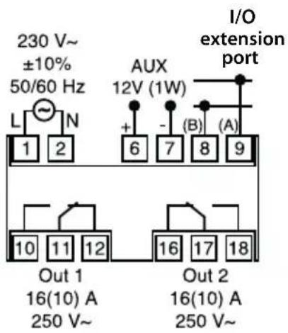
Connection of devices on the bus
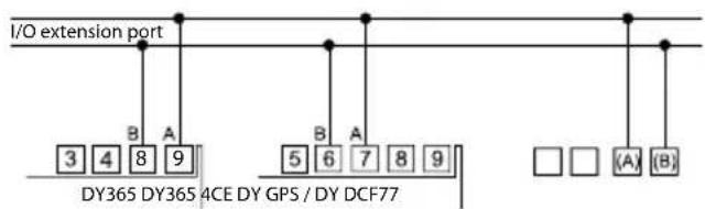
DY GPS / DY DCF77
DY GPS and DY DCF77 must be powered by a DC voltage at 12V. This power supply can be obtained from terminals 6-7 of DY365 (see figure).

Note: for details of the connections of the additional modules see the instructions supplied with the products.
DISPLAY AND KEYBOARD DESCRIPTION
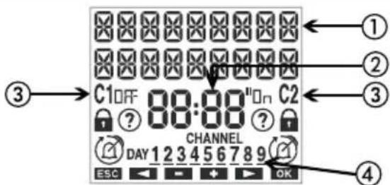
① General indications
② Time indication
③ Channel 1/channel 2 status indication On/Off
: active manual program
- blocked switchings
- active random switchings
C + □(flashing) : active cycle switchings
→: active holiday program
:active pulse program
④ Channels status indication (CHANNEL) / days of the week (DAY)
2 configured channel (in off status)
2 configured channel (in on status)
2 failed configured channel (no communication)

flowchart
graph TD
    ⑤ --> A["↓"]
    ⑥ --> B["↓"]
    ⑦ --> C["←"]
    ⑧ --> D["↑"]
    A --> E["←"]
    B --> F["←"]
    C --> G["←"]
    D --> H["←"]
⑤Turn on the display
Access the menu
ESC (one level back)
⑥ “◀”: decrease datum/previous menu/ switching channel 1/lock channel 1
“ ▶”: increase datum/next menu/ switching channel 2/lock channel 2
⑦ Confirm selection
⑧ Hardware reset
INITIAL OPERATION
- Once out of the package, DY365 is off: press the key → and wait a moment before activating the display
- The set language is English. To change it, press the key for at least 3 seconds. Choose among: German, English, Spanish, French, Italian, Russian and confirm with OK.
- Make connections following the diagrams on page 5 of this manual
- Power DY365: the backlight turns on permanently. Power possible additional connected modules (DY365 4CE, DY GPS...)
- The presence of the backup battery allows the DY365 to have updated date and time. To make the other settings follow the following steps:
Date - format: DD/MM/YY
- 1 ^st day of the week: Monday
Astronomical coordinates - country: France
- city: Paris
- latitude: North (48° 51' 36")
- longitude: East (2° 21' 00")
| Daylight Saving time (DST) change: active | - start of daylight saving time (DST): last Sunday of March at 02:00 o'clock- end of daylight saving time (DST): last Sunday of October at 03:00 o'clock |
Time correction: - sunrise: +0:00
- sunset: +0:00
Time zone: +1:00 UTC
Random switchings: - minimum: 1 minute
- maximum: 5 minutes
Cycle switchings: - ON duration: 1 minute
- OFF duration: 1 minute
PIN protection: disabled (---)
Bluetooth: disabled (Password: 000000)
GPS module: active
START PAGE (or main)

Information messages
- day of the week
- GPS status (if enabled)
- battery status (only if discharged)
-NO MA INS**
* See page 6. In this case there isn't any configured channel (no number turned on)
** Only if DY365 is not powered by mains.
In this condition the backlight is not active and the relay is in off status.
- Press the key:
to access the menu of the instrument
and scroll through the messages of DY365
ok to display the Bluetooth signal level or the calculated sunrise and sunset times***
*** The displayed times take into account possible entered values of correction (see page 16) if the display shows ____ means that the calculated sunrise time is after the sunset time if the display show ____ means that the calculated sunrise time is before 00:00 or that the calculated sunset is at 23:59
NOTE: The device is supplied with deactivated Bluetooth interface. To activate it, access Bluetooth menu (see page 54).
Access the store of your device, install and start the free app DBT TIMER


- 9 - User manual DY365
① Activate Bluetooth on DY365 device (see page 54).
② At the start the app displays the list of the associated DY365 devices. To associate a new device, press the symbol “*” in the upper right corner.
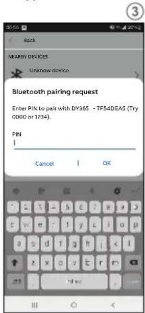
③ All the Bluetooth devices detected nearby are displayed: select the device to be associated from the list.
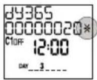
Note: each device is identified by the product code (for example DY365) and by the serial number (for example 00000020).
These informations can be viewed from the main page of the DY365
Warning: make sure that the DY365 is mains powered, Bluetooth interface is activated and that the display shows the main page (initial).
Otherwise the Bluetooth interface is not active and the device is not visible
④ Enter the password to associate the DY365 with your device
⑤ After successfully completing the procedure, the DY365 is added in the list of the associated devices.
Select the DY365 on which you want to act from the list of the associated devices
Note: communication between the app and the DY365 is point-to-point. This means that,
even in the presence of multiple DY365, the app can communicate with one only at a time.
The DY365 currently connected to the app displays the symbol * immediately after the serial number
⑥ The app displays the initial page of the selected DY365. From this page you can:
a. Create new programs that will then be copied to the DY365
b. Change the settings of the DY365
c. View the parameters and associate an alias to the DY365
d. Manually control the relay output/s and activate the random switching function or cycle function.
MENU DESCRIPTION
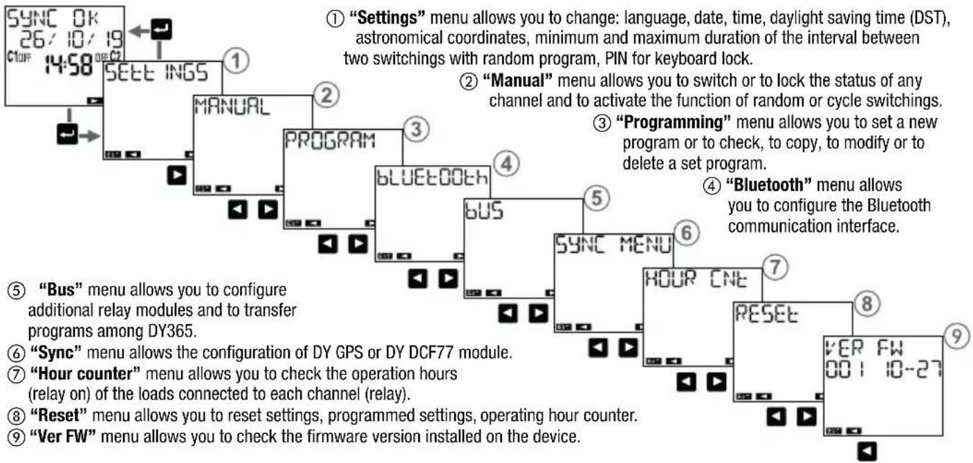
flowchart
graph TD
    A["1: "Settings" menu allows you to change: language, date, time, daylight saving time (DST), astronomical coordinates, minimum and maximum duration of the interval between two switchings with random program, PIN for keyboard lock."] --> B["2: "Manual" menu allows you to switch or to lock the status of any channel and to activate the function of random or cycle switchings."]
    B --> C["3: "Programming" menu allows you to set a new program or to check, to copy, to modify or to delete a set program."]
    C --> D["4: "Bluetooth" menu allows you to configure the Bluetooth communication interface."]
    D --> E["5: SYNC MENU"]
    E --> F["6: HOUR CNE"]
    F --> G["7: RESET"]
    G --> H["8: VER FW 00: 10-27"]
    H --> I["9: "Ver FW" menu allows you to check the firmware version installed on the device."]
- 11 - User manual DY365
SETTINGS MENU
"Settings" menu allows you to view and eventually to modify the the general operation settings of DY365, such as:
① language
② date
③ time
④ automatic daylight saving time (DST) change
⑤ position (astronomical coordinates)
⑥ interval duration between two random switchings
⑦ ON and OFF time duration for cycle switchings
⑧ keys protection by PIN

flowchart
graph TD
    A["SETT INGS LANGUAGE"] --> B["SETT INGS DATE"]
    B --> C["SETT INGS TIME"]
    C --> D["SETT INGS DAYL SAVE"]
    D --> E["SETT INGS ASTRO"]
    E --> F["SETT INGS RANDOM"]
    F --> G["SETT INGS CYCLE"]
    G --> H["SETT INGS PIN"]
Language setting menu

flowchart
graph TD
    A["SYNC 0K\n26/10/19\nC1OFF 14:58 OFF C2"] --> B["SETT INGS"]
    B --> C["OK"]
    C --> D["SETT INGS LANGUAGE"]
    D --> E["OK"]
    E --> F["LANGUAGE DEUTSCH"]
    F --> G["LANGUAGE ENGL ISH"]
    G --> H["LANGUAGE ESPANOL"]
    H --> I["LANGUAGE FRANCA IS"]
    I --> J["LANGUAGE ITAL IANO"]
    J --> K["LANGUAGE RUSSK 19"]
Date setting menu

flowchart
graph TD
    A["SYNC 0K\n26/10/19\nC10F 14:58 OFF C2"] --> B["SETT INGS"]
    B --> C["OK"]
    C --> D["SETT INGS\nDATE"]
    D --> E["OK"]
    E --> F["FORMATE\ndd/MM/yy"]
    F --> G["OK"]
    G --> H["Parameters modification"]

    style A fill:#f9f,stroke:#333
    style B fill:#ccf,stroke:#333
    style C fill:#cfc,stroke:#333
    style D fill:#fcc,stroke:#333
    style E fill:#cff,stroke:#333
    style F fill:#ffc,stroke:#333
    style G fill:#cfc,stroke:#333
    style H fill:#fcc,stroke:#333
③ Enter the date: day, month, year.
If DY GPS is connected and active, DY365 synchronizes date, time and coordinates (longitude, latitude) thanks to the received GPS signal. If DY DCF77 is connected and active, DY365 synchronizes date and time only. Synchronization occurs automatically every 30 minutes and is indicated by flashing the field "Time" (2 times). The data received from DY GPS / DY DCF77 overwrite possible changes made manually.
Time setting menu

flowchart
graph TD
    A["SYNC 0K\n26/10/19\nC1OFF 14:58 OFF C2"] --> B["SETT INGS"]
    B --> C["OK"]
    C --> D["SETT INGS\nTIME"]
    D --> E["OK"]
    E --> F["TIME\n08:28\nTIME ZONE\n1:00"]
    F --> G["Ok"]
    G --> H["Parameters modification"]
    style A fill:#f9f,stroke:#333
    style H fill:#f9f,stroke:#333
① Set the time: hours, minutes.
② Set the time zone*. Range: -14:00 ÷ +14:00 (at 15 minutes steps). For Italy set +1:00.
* The time zone must be set manually also with connected DY GPS module.
If DY GPS is connected and active, DY365 synchronizes date, time and coordinates (longitude, latitude) thanks to the received GPS signal. If DY DCF77 is connected and active, DY365 synchronizes date and time only. Synchronization occurs automatically every 30 minutes and is indicated by flashing the field "Time" (2 times). The data received from DY GPS / DY DCF77 overwrite possible changes made manually.
Daylight saving time (DST)/winter time (CET) change setting menu
Daylight saving time (DST)/winter time(CET) change and vice versa can occur in an automatic way. In this case, DY365:
- increases by an hour in the passage from winter time (CET) to daylight saving time (DST)
- decreases by an hour in the passage from daylight saving time (DST) to winter time (CET)
For every change it's necessary to specify:

the week of the month during which the time change occurs (first, second, third, fourth, last)

the day of the week
(Monday: 1, Tuesday: 2, ...)

the month the hour

In Italy, for example, daylight saving time (DST) begins occurs the last (LAST) Sunday (7) of March (D3 at October, and ends the last (LAST) Sunday (7) of October (10) at D'sock.

flowchart
graph TD
    A["SYNC 0K 26/10/19 C1 OFF 14:58 OFF C2"] --> B["SETT INGS"]
    B --> C["OK"]
    C --> D["SETT INGS dRYL SAVE"]
    D --> E["OK"]
    E --> F["dRYL SAVE AUTO ON"]
    F --> G["①"]
    G --> H["Ok"]
    H --> I["Parameters modification"]
    I --> J["②"]
    J --> K["SUMMER LAST /03 02:00"]
    K --> L["③"]
    L --> M["WINTER LAST /10 03:00"]
    M --> N["OK"]
    N --> O["Set date and time of the winter time (CFT)-daylight saving time (DST) change."]
① Choose to activate (A) or to disable ( ) the automatic time change.
② Set date and time of the winter time (CET)-daylight saving time (DST) change.
③ Set date and time of the daylight saving time (DST)-winter time (CET) change.
Astronomical coordinates setting menu
The setting of the geographical coordinates of the installation place allows DY365 to calculate, for each day of the year, sunrise and sunset times.
To simplify the procedure, in the DY365 are stored the coordinates of the locations listed below; if your location is among them you can select it from the menu ①, otherwise it's necessary to enter the coordinates of latitude and longitude (menu ②)③
Note: the display on point ① shows “----” if the coordinates have been entered manually or captured via DY GPS.
Location stored in DY365: Major cities of France, Germany, Italy, Russia, Spain, United Kingdom and some other major cities in the rest of the world
The correction of sunrise and sunset times is useful for applications that require the turning on of lights in particular localities. It's possible, in fact, that the presence of disturbing elements, such as the mountains, can influence actual times of sunrise and sunset, making it necessary to advance or delay of a few minutes the calculated times.
The twilight is the time interval before sunrise, or after sunset, characterized by the permanence of the light due to the spread by the atmosphere of the Sun light. During these time intervals it's possible to distinguish clearly objects and conduct outdoor activities without using additional lighting. Therefore, in some applications it is more interesting to take as times of switching on and off the twilight (civil) in place of sunrise and sunset. With DY365 it's possible to choose to turn on/off the loads depending on the times of sunrise and sunset or the civil twilight. The calculated time correction also applies to the times of twilight. To view the calculated switching on time (sunset) and switching off time (sunrise), from the main page press the key ok (see page 8).

flowchart
graph TD
    A["SYNC 0K\n26/10/19\nC1OFF 14:58 OFF C2"] --> B["SETT INGS"]
    B --> C["OK"]
    C --> D["SETT INGS\nASTRO"]
    D --> E["OK"]
    E --> F["CITY"]
    F --> G["OK"]
    G --> H["Parameters modification"]
    style A fill:#f9f,stroke:#333
    style B fill:#ccf,stroke:#333
    style C fill:#cfc,stroke:#333
    style D fill:#fcc,stroke:#333
    style E fill:#cff,stroke:#333
    style F fill:#ffc,stroke:#333
    style G fill:#cfc,stroke:#333
    style H fill:#fcc,stroke:#333
① Choose the installation location. If it's not present, proceed with steps② and ③
② Set the latitude of installation place.
③ Set the longitude of installation location.
④ Set a possible correction of the calculated sunrise time. Positive values to delay, negative values to anticipate.
⑤ Set a possible correction of the calculated sunset time. Positive values to delay, negative values to anticipate.
⑥ Choose as switching times the civil twilight ( ) in place of sunrise and sunset
( C IV IL N ) times.
If DY GPS is connected and active, DY365 synchronizes date, time and coordinates (longitude, latitude) thanks to the received GPS signal. If DY DCF77 is connected and active, DY365 synchronizes date and time only. Synchronization occurs automatically every 30 minutes and is indicated by flashing the field "Time" (2 times). The data received from DY GPS / DY DCF77 overwrite possible changes made manually.
Random switchings setting menu

flowchart
graph TD
    A["SYNC 0K\n26/10/19\nC10FF 14:58 OFF C2"] --> B["SETT INGS"]
    B --> C["OK"]
    C --> D["SETT INGS RANDOM"]
    D --> E["OK"]
    E --> F["dURAT ION MIN\n00:01\n00:05"]
    F --> G["OK"]
    G --> H["Parameters modification"]
    style A fill:#f9f,stroke:#333
    style H fill:#f9f,stroke:#333
The “random switching ⑦” function (manual menu → random manual) allows you to automatically switch and at random time intervals any channel among the 8 available.
In this menu it's possible to define the minimum and maximum duration of the time interval between two random switchings. Default minimum duration is 1 minute, maximum duration is 5 minutes.
Parameters modification
① Set the minimum duration. It's possible to set values between 1 minute and the maximum duration.
② Set the maximum duration. It's possible to set values between the minimum duration and 23:59.
Note: setting the minimum duration equal to the maximum, the switchings will occur at fixed time intervals.
Cycle switchings setting menu

flowchart
graph TD
    A["SYNC 0K\n26/10/19\nC1OFF 14:58 OFF C2"] --> B["SETT INGS"]
    B --> C["OK"]
    C --> D["SETT INGS\nCYCLE"]
    D --> E["OK"]
    E --> F["dURAT ION\nON\n00:0 I"]
    F --> G["OK"]
    G --> H["Parameters modification"]
    F --> I["dURAT ION\nOFF\n00:0 I"]
    I --> J["OK"]
    J --> K["OK"]
    K --> L["OK"]
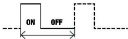
The "cycle switching" function (manual menù → cycle manual) is a succession of on and off switching.
The cycle programme always starts from the on status. In this menu it's possible to define the duration of on and off.
The duration of the on and off duration cannot be less than one minute.
Default on duration: 1 minute, OFF duration: 1 minute
Parameters modification
① Set the ON duration. It's possible to set values between 1 minute and 99:59 hours.
② Set the OFF duration. It's possible to set values between 1 minute and 99:59 hours.
Protection PIN setting menu

flowchart
graph TD
    A["SYNC 0K\n26/10/19\nC1OFF 14:58 OFF C2"] --> B["SETT INGS"]
    B --> C["OK"]
    C --> D["SETT INGS\nP IN"]
    D --> E["OK"]
    E --> F["P IN"]
    F --> G["..."]
    style A fill:#f9f,stroke:#333
    style B fill:#ccf,stroke:#333
    style C fill:#cfc,stroke:#333
    style D fill:#fcc,stroke:#333
    style E fill:#cff,stroke:#333
    style F fill:#ffc,stroke:#333
The protection code (PIN) is used to lock the keyboard and prevent changes by unauthorized persons. With active PIN protection, pressing any key, it's necessary to enter the PIN: if PIN is correct the keyboard unlocks; after 3 minutes without pressing a key, the keyboard will lock automatically.
To activate PIN protection:
- set a value between 000 and 999
To disable PIN protection:
- set “---” (located before 000 or after 999)
Note: If you have forgotten your PIN code to unlock DY365 it's necessary to carry out a hardware reset (see page 66).
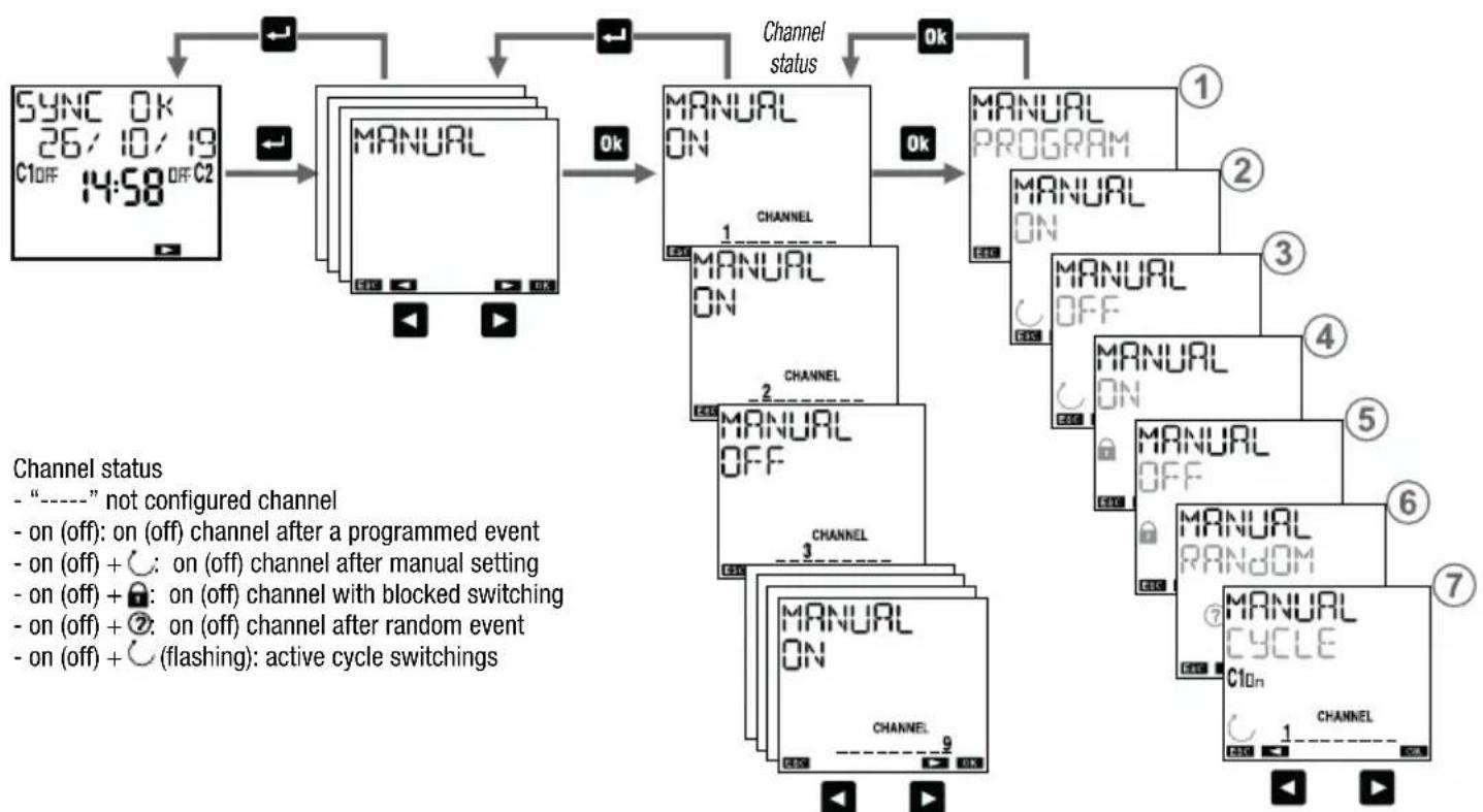
"Manual" menu allows you to manually take action on the channels of DY365 and to check their status (on, off, or "----" if the channel is not configured).
Possible operations:
① program: the selected channel follows the set programming
② temporary on ⏻ : the selected channel is set on until the next programmed off event
③ temporary off ⬇: the selected channel is set off until the next programmed on event
④ permanent on ☑: the selected channel is locked in on position until the manual unlocking (to unlock, access this menu and set a different operation)
⑤ permanent off 🔒: the selected channel is locked in off position until the manual unlocking (to unlock, access this menu and set a different operation)
⑥ random Ⓩ: the selected channel is set on and then will take place switching on / off at random intervals (the minimum and maximum interval can be set from “Settings → random” menu)
⑦ cycle: the selected channel is set on and then will take place switching on / off (the ON and OFF duration can be set from "Settings → cycle" menu)
flowchart
graph TD
    A["SYNC 0K 26/10/19 C1off 14:58 OFF C2"] --> B["MANUAL"]
    B --> C["MANUAL ON"]
    C --> D["MANUAL PROGRAM"]
    D --> E["MANUAL ON"]
    E --> F["MANUAL OFF"]
    F --> G["MANUAL ON"]
    G --> H["MANUAL ON"]
    H --> I["MANUAL ON"]
    I --> J["MANUAL ON"]
    J --> K["MANUAL ON"]
    K --> L["MANUAL ON"]
    L --> M["MANUAL ON"]
    M --> N["MANUAL ON"]
    N --> O["MANUAL ON"]
    O --> P["MANUAL ON"]
    P --> Q["MANUAL ON"]
    Q --> R["MANUAL ON"]
    R --> S["MANUAL ON"]
    S --> T["MANUAL ON"]
    T --> U["MANUAL ON"]
    U --> V["MANUAL ON"]
    V --> W["MANUAL ON"]
    W --> X["MANUAL ON"]
    X --> Y["MANUAL ON"]
    Y --> Z["MANUAL ON"]
    Z --> AA["MANUAL ON"]
    AA --> AB["MANUAL ON"]
    AB --> AC["MANUAL ON"]
    AC --> AD["MANUAL ON"]
    AD --> AE["MANUAL ON"]
    AE --> AF["MANUAL ON"]
    AF --> AG["MANUAL ON"]
    AG --> AH["MANUAL ON"]
    AH --> AI["MANUAL ON"]
    AI --> AJ["MANUAL ON"]
    AJ --> AK["MANUAL ON"]
    AK --> AL["MANUAL ON"]
    AL --> AM["MANUAL ON"]
    AM --> AN["MANUAL ON"]
    AN --> AO["MANUAL ON"]
    AO --> AP["MANUAL ON"]
    AP --> AQ["MANUAL ON"]
    AQ --> AR["MANUAL ON"]
    AR --> AS["MANUAL ON"]
    AS --> AT["MANUAL ON"]
    AT --> AU["MANUAL ON"]
    AU --> AV["MANUAL ON"]
    AV --> AW["MANUAL ON"]
    AW --> AX["MANUAL ON"]
    AX --> AY["MANUAL ON"]
    AY --> AZ["MANUAL ON"]
    AZ --> BA["MANUAL ON"]
    BA --> BB["MANUAL ON"]
    BB --> BC["MANUAL ON"]
    BC --> BD["MANUAL ON"]
    BD --> BE["MANUAL ON"]
    BE --> BF["MANUAL ON"]
    BF --> BG["MANUAL ON"]
    BG --> BH["MANUAL ON"]
    BH --> BI["MANUAL ON"]
    BI --> BJ["MANUAL ON"]
    BJ --> BK["MANUAL ON"]
    BK --> BL["MANUAL ON"]
    BL --> BM["MANUAL ON"]
    BM --> BN["MANUAL ON"]
    BN --> BO["MANUAL ON"]
    BO --> BP["MANUAL ON"]
    BP --> BQ["MANUAL ON"]
    BQ --> BR["MANUAL ON"]
    BR --> BS["MANUAL ON"]
    BS --> BT["MANUAL ON"]
    BT --> BU["MANUAL ON"]
    BU --> BV["MANUAL ON"]
    BV --> BW["MANUAL ON"]
    BW --> BX["MANUAL ON"]
    BX --> BY["MANUAL ON"]
    BY --> BZ["MANUAL ON"]
- 24 - User manual DY365
Shortcut keys
For channel aboard the DY365 (channel 1-2) it's possible to set the operations described on pag. 21 through a combination of keys:
- temporary on/off:
press the key ▲ for channel 1 or ▶ for channel 2. If on becomes off and vice versa.
- permanent on/off:
press for a long time (for 3 seconds at least) the key for channel 1 or or channel 2. The current state is locked until the unlocking (press again for a long time the key or).
- random:
press contemporary and for a long time (for 3 seconds at least) the key ok and ▶ for channel 1 or ▶r channel 2. Press again simultaneously and for a long time the keys ok and ▶t to ▶r isable the function.
- cycle:
press contemporary and for a long time (for 3 seconds at least) the keys → and ▶ for channel 1 or ▶ for channel 2. Press again simultaneously and for a long time the keys → and ▶ t▶ isable the function.
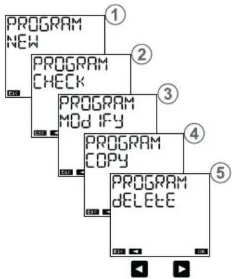
PROGRAM MENU
The menu "program" allows you to:
① create a new program
② check created programs
③ change or delete a created program
④ copy all created programs on a channel in another channel
⑤ delete all programs of a channel
Channels selection
scroll through the channels from 1 to 8:
- by pressing the key ▶ to move to the next channel without selecting the current channel
- by pressing the key Ok to select/deselect the current channel and move to the next

flowchart
graph LR
    A["CHANNEL 1"] --> B["CHANNEL 2"]
    B --> C["CHANNEL 3"]
    C --> D["CHANNEL 34"]
    D --> E["Multi-channel Processing"]
    E --> F["CHANNEL 35"]
    F --> G["CONF IRM Channel 35"]
    G --> H["OK"]
Select days
scroll through the days of the week from 1 to 7:
- by pressing the key ▶ to move to the next day without selecting the current day
- by pressing the key ok to select/deselect the current day and move to the next

flowchart
graph LR
    A["DAY 1"] --> B["DAY 2"]
    B --> C["DAY 3"]
    C --> D["DAY 34"]
    D --> E["Conferencing Box"]
    E --> F["DAY 35"]
    F --> G["CONF IRM"]
    G --> H["OK"]
Programs types
- Program ON/OFF: it is composed of a switching of the ON relay and of a subsequent switching of the OFF relay. It can have a daily period (everyday with the same modes), weekly (every week with the same modes), annual (every year with the same modes)*.
- PULSE ON Program: is an ON relay switching for a maximum duration of 59 seconds. It can have a daily period (everyday with the same modes), weekly (every week with the same modes), annual (every year with the same modes)*.
- PULSE OFF program: is a relay switching OFF for a maximum duration of 59 seconds. It can have daily period (everyday with the same modes), weekly (every week with the same modes), annual (every year with the same modes)*.
- HOLIDAY program: is a period of time defined by a start time and an end time within which all programmed switchings (of that channel) are disabled. The relay is in OFF position (OFF holiday) or in ON position (ON holiday).
* In the annual program, it's possible to specify the month. In this case, the period is monthly (every month with the same modes). It's also possible to specify a definite date (the program carried out only once).
Channel types
• TIME channel: carries out programs of time type: ON / OFF, ON pulse, OFF pulse, holiday
- ASTRO channel: carries out programs of astronomical type, i.e. in the interval delimited by sunrise and sunset**: ON/OFF, ON pulse, OFF pulse, holiday, night programs (see pages 36-37). ON switchings set before sunset are carried out at sunset, OFF switchings set after sunrise are carried out at sunrise (except for some night programs that can have switching on or switching off during the day. See on page 36).
** times of sunrise and sunset are automatically calculated by DY365 according to geographic coordinates set during installation. In place of sunrise and sunset times it's possible to use the times of civil twilight (see page 18).
⚠ Important: on the same channel can't coexist ON pulses and OFF pulses (if an ON pulse is already present, it's not possible to save a holiday OFF program and vice versa).
Important: on the same channel can't coexist holiday ON programs and holiday OFF programs (if a holiday ON program is already present, it's not possible to save a holiday OFF program and vice versa).
Important: a channel may be either of clockwise or of astronomical type, but it can't be of both types simultaneously. It's not possible to save programs of astronomical type on a channel where are stored programs of time type (and vice versa). Messages of ERROR 011 (astro program on channel astro) and E (one program on astro channel). In this case to proceed it's necessary to delete the saved programs on that channel (see page 53).
Programs priority
The priority programs defines how DY365 manages the case in which programs with different period are running at the same time (1 indicates higher priority).
| Program | Date* Annual Monthly Weekly Daily | ||||
| Holiday 1 | |||||
| Night 2 | |||||
| Pulse 3 | |||||
| On/Off 45678 | |||||
* Date: select day, month, year (program carried “only once in the life of the product”). If the month is not specified, the program is carried out all days xx of all months of the specified year.
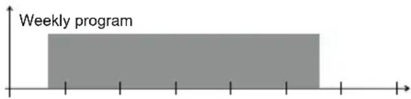
Priority list on/off
In case in which, on the same channel, on/off programs are provided with different period (daily, weekly, ...) to carry out in the same day, only the program with the highest priority is executed.
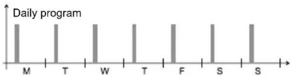


From this example it's possible to see that the daily event on Monday is not carried out because in the same day it is provided the beginning of the week program (even if the daily program
of Monday begins and ends before the beginning of the weekly program). Instead, the daily program of Sunday is carried out because it's the only one running for that day.
Holiday program
The holiday program just begins and ends exactly at the specified times.


bar
Carried out program | Month | Status | |---|---| | M | Carried out program | | T | Carried out program | | W | Carried out program | | T | Carried out program | | F | Carried out program | | S | Carried out program | | S | Carried out program |
flowchart
graph TD
    A["SYN C 0K 26/10/19 C1 OFF 14:58 OFF C2"] --> B["PROGRAM"]
    B --> C["OK"]
    C --> D["PROGRAM NEW"]
    D --> E["OK"]
    E --> F["NEW CHANNEL"]
    F --> G["CHANNEL 1"]
    G --> H["CHANNEL 2"]
    H --> I["NEW CHANNEL 3 5 9"]
    I --> J["NEW CONF IRM 3 5 7"]
    J --> K["OK"]
    style A fill:#f9f,stroke:#333
    style K fill:#f9f,stroke:#333
- 31 - User manual DY365
Program menu: new daily timed

-on/off: on time and off time
- on pulse: time and pulse duration (max 59 seconds)
- off pulse: time and pulse duration (max 59 seconds)
Program menu: new weekly timed

flowchart
graph TD
    A["NEW\nt IMED\nASTRO"] -->|Ok| B["t IMED\ndAILY"]
    B -->|Ok| C["WEEKLY\nON - OFF\nWEEKLY\nPULSE ON\nWEEKLY\nPULSE OFF"]
    C -->|Ok| D["Enter program parameters"]
Program parameters
- on/off: day (or days)* and on time, day (or days) and off time
- on pulse: day (or days)* and pulse time, pulse duration (max 59 seconds)
- off pulse: day (or days)* and pulse time, pulse duration (max 59 seconds)
* See "Days selection" on page 27
Program menu: new yearly timed (or monthly)

flowchart
graph TD
    A["NEW\nt IMed"] -->|Ok| B["t IMEd\ndAILY"]
    C["NEW\nASTRO"] -->|Ok| D["t IMEd\nWEEKLY"]
    E["YEARLY ON - OFF"] -->|Ok| F["YEARLY\nPULSE ON"]
    G["t IMED\nHOLIDAY"] -->|Ok| H["YEARLY\nPULSE OFF"]
    style A fill:#ccc,stroke:#333
    style C fill:#ccc,stroke:#333
    style E fill:#ccc,stroke:#333
    style G fill:#ccc,stroke:#333
    style B fill:#ccc,stroke:#333
    style D fill:#ccc,stroke:#333
    style F fill:#ccc,stroke:#333
    style H fill:#ccc,stroke:#333
    note right of A: English
    note right of B: Enter program parameters
    note right of F: Enter program parameters
    note right of G: Enter program parameters
Program parameters
- on/off: day (or days) and on time, day (or days) and off time
- on pulse: day (or days) and pulse time, pulse duration (max 59 seconds)
- off pulse: day (or days) and pulse time, pulse duration (max 59 seconds)
How to choose the day (or days) in an annual program (or monthly)

flowchart
graph LR
    A["Ok"] --> B["1 WEEK 1\n---/MM/yy\nOn"]
    B --> C["2 WEEK 2\nWEEK 3\nWEEK 4\nLAST"]
    C --> D["3 LAST\n---/MM/yy\nOn\nDAY"]
    D --> E["4 DATE\n---/MM/yy\nOn"]
① to set the program:
in the first, second, third, fourth or last week of the month in / the day/s (Monday, ...) of the week just specified the specified month (MM for all months) the given year (YY for all years)
Note: the on event must correspond to the off in the same day. For example, if the program includes two events on Monday and on Wednesday, then there will be two off events on Monday and on Wednesday. Otherwise ERROR 010 is signaled.
② to set the program on the last day:
--/MM/99 of all months of all years
---/V/V/99 of the specified V/V month of all years
---/MM/ZZ of all months of the specified ZZ year
---/VV/ZZ of the specified VV month of the specified ZZ year
③ to set the program on the day XX (1,2,3...):
xx/MM/99 of all months of all years
xx/4V/99 of the specified VV month of all years
xx/MM/ZZ of all months of the specified ZZ year
××/V/V/ZZ of the specified VV month of the specified ZZ year
Program menu: new holiday timed

flowchart
graph TD
    A["NEW t IMED"] -->|OK| B["t IMED dA ILY"]
    B -->|OK| C["HOL IDAY OFF"]
    C -->|OK| D["HOL IDAY ON"]
    D -->|OK| E["Enter program parameters"]
    style A fill:#ccc,stroke:#333
    style B fill:#ccc,stroke:#333
    style C fill:#ccc,stroke:#333
    style D fill:#ccc,stroke:#333
    style E fill:#ccc,stroke:#333
① HOLIDAY OFF: the relay is OFF from the beginning to the end of Holiday program
② HOLIDAY ON: the relay is ON from the beginning to the end of Holiday program
Program parameters
- beginning of the program
- end of the program
How to choose the day (or days) in a holiday program

flowchart
graph LR
    A["Ok"] --> B["1 WEEK 1\n---/MM/yy\nOn"]
    B --> C["2 WEEK 2\nWEEK 3\nWEEK 4\nLAST"]
    C --> D["3 LAST\n---/MM/yy\nOn\nDAY"]
    D --> E["4 DATE\n---/MM/yy\nOn"]
① to set the program:
in the first, second, third, fourth or last week of the month in / the day/s (Monday, ...) of the week just specified the specified month (MM for all months) the given year (YY for all years)
Nota: in this case, the holiday program must begin and end in the same day. Otherwise ERROR 010 is signaled.
② to set the program on the last day:
--/MM/99 of all months of all years
---/V/V/99 of the specified V/V month of all years
---/MM/ZZ of all months of the specified ZZ year
---/VV/ZZ of the specified VV month of the specified ZZ year
③ to set the program on the day XX (1,2,3...):
xx/MM/99 of all months of all years
xx/4V/99 of the specified VV month of all years
xx/MM/ZZ of all months of the specified ZZ year
××/V/V/ZZ of the specified V/V month of the specified ZZ year
Program menu: new astro night

flowchart
graph TD
    A["English"] --> B["NEW T I MED"]
    B --> C["NEW ASTRO"]
    C --> D["ASTRO NIGHT"]
    D --> E["ASTRO DAILY"]
    E --> F["ASTRO WEEKLY"]
    F --> G["ASTRO YEARLY"]
    G --> H["ASTRO HOL IDAY"]
    H --> I["NIGHT DAY 12"]
    I --> J["NIGHT DAY 23"]
    J --> K["NIGHT DAY 7"]
    K --> L["NIGHT CONF IRM CHANNEL ? 3-5 Channel"]
    L --> M["Nights programs"]
    M --> N["S ON R"]
    N --> O["S OFF R"]
    O --> P["S OFFON R"]
    P --> Q["S OFF"]
    Q --> R["ON R"]
    R --> S["OK"]
    style A fill:#f9f,stroke:#333
    style M fill:#ccf,stroke:#333
How to select nights
scroll through the nights of the week from the first (1-2) to the last (7-1):
- by pressing the key ▶ key to move to the next night without selecting the current night
- by pressing the key ok to select/deselect the current night and move to the next

flowchart
graph LR
    A["OK"] --> B["DAY12"]
    C["OK"] --> D["DAY123"]
    E["..."] --> F["DAY1234"]
    G["OK"] --> H["DAY12345"]
    I["..."] --> J["DAY123456"]
    K["..."] --> L["DAY1234567"]
    M["..."] --> N["DAY123457"]
    O["NIGHT CONF IRM"] --> P["?"]
    P --> Q["DAY12345"]
    Q --> R["..."]
How to interpret the selection
If the night between the days of A and B is selected, the day A is on and underlined while B is on (not underlined).
Examples of selection:
DAY12345 Selected nights: between day 1 and 2, between day 2 and 3, between day 3 and 4, between day 4 and 5
DAY12345 Selected nights: between day 1 and 2, between day 2 and 3, between day 4 and 5
DAY1234 7 Selected nights: between day 1 and 2, between day 3 and 4, between day 7 and 1
Night programs

Turning on at sunset, turning off at sunrise. No parameter required.
Off from sunset to sunrise. No parameter required.
* If off time is before sunset switching is not carried out. If on time is after sunrise switching is not carried out.
** Switching on continues for the entire set time interval (also if off time is after sunrise).
*** Switching on occurs before sunrise of the entire set time interval (also if on time is before sunset).
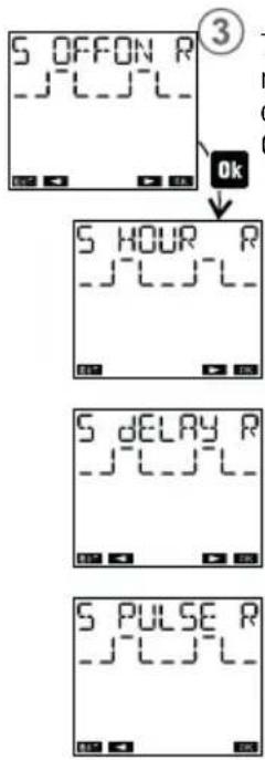
flowchart
graph TD
    A["OFFON R"] --> B["OK"]
    B --> C["5 HOUR R"]
    C --> D["5 DELAY R"]
    D --> E["5 PULSE R"]
Turning on at sunset, turning off during the night. Turning on during the night, turning off at sunrise.
Choose one of the three following cases:
Turning on at sunset, turning off at a settable time.
Turning on at a settable time, turning off at sunrise. (*)
Turning on at sunset, turning off after a settable time interval.
Turning on before sunrise of a settable time interval, turning off at sunrise.
Turning on at sunset for a settable short duration (pulse, max 59 seconds).
Turning on at sunrise for a short settable duration (pulse, max 59 seconds).

Turning on at sunset, turning off during the night.
Choose one of the three following cases:
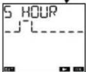
Turning on at sunset, turning off at a settable time. (*)(**)
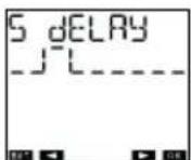
Turning on at sunset, turning off after a settable time interval. (**)

Turning on at sunset for a settable short duration (pulse, max 59 seconds).

Turning on during the night, turning off at sunrise.
Choose one of the three following cases:
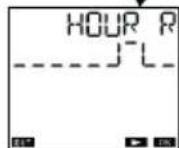
Turning on at a settable time, turning off at sunrise. (*)(***)

Turning on before sunrise of a settable time interval, turning off at sunrise. (***

Turning on at sunrise for a settable short duration (pulse, max 59 seconds).
Program menu: new astro daily

flowchart
graph TD
    A["NEW t IMED"] --> B["ASTRO NIGHT"]
    C["NEW ASTRO"] --> B
    B --> D["dA lly ON - OFF"]
    D --> E["Enter program parameters"]
    F["ASTRO WEEKLY"] --> G["dA lly PULSE ON"]
    H["ASTRO YEARLY"] --> I["dA lly PULSE OFF"]
    J["ASTRO HOL IDAY"] --> K["..."]
    style A fill:#f9f,stroke:#333
    style C fill:#f9f,stroke:#333
    style F fill:#f9f,stroke:#333
    style J fill:#f9f,stroke:#333
Program menu: new astro weekly

flowchart
graph TD
    A["Start"] --> B["NEW TIMEED"]
    B --> C["NEW ASTRO"]
    C --> D["ASTRO NIGHT"]
    D --> E["ASTRO DAILY"]
    E --> F["ASTRO WEEKLY"]
    F --> G["ASTRO YEARLY"]
    G --> H["ASTRO HOL IDAY"]
    H --> I["Enter program parameters"]

    style A fill:#f9f,stroke:#333
    style B fill:#ccf,stroke:#333
    style C fill:#cfc,stroke:#333
    style D fill:#fcc,stroke:#333
    style E fill:#cff,stroke:#333
    style F fill:#ffc,stroke:#333
    style G fill:#cfc,stroke:#333
    style H fill:#fcc,stroke:#333
    style I fill:#ffc,stroke:#333

    note1["Program parameters\n- on/off: day (or days)* and on time, day (or days) and off time\n- on pulse: day (or days)* and pulse time, pulse duration (max 59 seconds)\n- off pulse: day (or days)* and pulse time, pulse duration (max 59 seconds)\n* See "Days selection" on page 27"]
Program menu: new astro yearly (or monthly)

flowchart
graph TD
    A["NEW TIME"] --> B["NEW ASTRO"]
    B --> C["ASTRO NIGHT"]
    C --> D["ASTRO DAILY"]
    D --> E["ASTRO WEEKLY"]
    E --> F["ASTRO YEARLY"]
    F --> G["ASTRO HOL IDAY"]
    G --> H["YEARLY ON - OFF"]
    H --> I["YEARLY PULSE ON"]
    I --> J["YEARLY PULSE OFF"]
    J --> K["Enter program parameters"]
How to choose the day (or days) in an astro annual program (or monthly)

flowchart
graph LR
    A["Ok"] --> B["1 WEEK 1\n----/MM/yy\nOn"]
    B --> C["2 WEEK 2\nWEEK 3\nWEEK 4\nLAST"]
    C --> D["3 LAST\n----/MM/yy\nOn\nDAY"]
    D --> E["4 DATE\n----/MM/yy\nOn"]
① to set the program:
in the first, second, third, fourth or last week of the month in / the day/s (Monday, ...) of the week just specified the specified month (MM for all months) the given year (YY for all years)
Note: the on event must correspond to the off in the same day. For example, if the program includes two events on Monday and on Wednesday, then there will be two off events on Monday and on Wednesday. Otherwise ERROR 010 is signaled.
② to set the program on the last day:
---/MM/99 of all months of all years
---/V/V/99 of the specified V/V month of all years
--/MM/ZZ of all months of the specified ZZ year
---/VV/ZZ of the specified VV month of the specified ZZ year
③ to set the program on the day XX (1,2,3...):
xx/MM/99 of all months of all years
xx/4V/99 of the specified VV month of all years
××/MM/ZZ of all months of the specified ZZ year
xx/VV/ZZ of the specified VV month of the specified ZZ year
Program menu: new astro holiday

flowchart
graph TD
    A["NEW t IMED"] --> B["ASTRO dA ILY"]
    C["NEW ASTRO"] --> B
    B --> D["ASTRO WEEKLY"]
    D --> E["ASTRO YEARLY"]
    E --> F["ASTRO HOL IDAY"]
    G["HOL IDAY OFF"] --> H["①"]
    I["HOL IDAY ON"] --> J["②"]
    K["Enter program parameters"] --> L["①"]
    M["②"] --> N["②"]
① HOLIDAY OFF: the relay is OFF from the beginning to the end of holiday program.
② HOLIDAY ON: the relay is ON from the beginning to the end of holiday program.
Program parameters
- beginning of the program
- end of the program
How to choose the day (or days) in a holiday astro program

flowchart
graph LR
    A["Ok"] --> B["1 WEEK 1\n---/MM/yy\nOn"]
    B --> C["2 WEEK 2\nWEEK 3\nWEEK 4\nLAST"]
    C --> D["3 LAST\n---/MM/yy\nOn\nDAY"]
    D --> E["4 DATE\n---/MM/yy\nOn"]
① to set the program:
in the first, second, third, fourth or last week of the month in / the day/s (Monday, ...) of the week just specified the specified month (MM for all months) the given year (YY for all years)
Note: in this case, the holiday program must begin and end in the same day. Otherwise ERROR 0 10 is signaled.
② to set the program on the last day:
--/MM/99 of all months of all years
---/V/V/99 of the specified V/V month of all years
---/MM/ZZ of all months of the specified ZZ year
---/VV/ZZ of the specified VV month of the specified ZZ year
③ to set the program on the day XX (1,2,3...):
xx/MM/99 of all months of all years
xx/4V/99 of the specified VV month of all years
××/MM/ZZ of all months of the specified ZZ year
××/V/V/ZZ of the specified VV month of the specified ZZ year
Program menu: check

flowchart
graph TD
    A["SYNC 0K<br>26/10/19<br>C10F 14:58 OFF C2"] --> B["PROGRAM"]
    B --> C["PROGRAM CHECK"]
    C --> D["MEMORY<br>076 * 450"]
    D --> E["OK"]
    B --> F["OK"]
    C --> G["OK"]
    style A fill:#f9f,stroke:#333
    style B fill:#ccf,stroke:#333
    style C fill:#ccf,stroke:#333
    style D fill:#cfc,stroke:#333
    style E fill:#fcc,stroke:#333
How to check a program
① choose the channel: 1 ... 8
② choose the period: daily, weekly, annual, holiday or night (when it is a channel of astronomical type)
③ choose the type: on/off, on pulse, off pulse or a night program (only if it is a channel of astronomical type)
Note: a program requires more screens to be displayed:
- press the key ok to move from the first to the second part of the same program
- press the keys ▶ and ▶ switch from one program to another

flowchart
graph TD
    A["Choose the channel"] --> B["1"]
    B --> C["CHANNEL CHECK"]
    C --> D["2"]
    D --> E["CHANNEL CHECK"]
    E --> F["3"]
    F --> G["CHANNEL CHECK"]
    G --> H["4"]
    H --> I["CHANNEL CHECK"]
    I --> J["5"]
    J --> K["CHANNEL CHECK"]
    K --> L["6"]
    L --> M["CHANNEL CHECK"]
    M --> N["7"]
    N --> O["CHANNEL CHECK"]
    O --> P["8"]
    P --> Q["CHANNEL CHECK"]
    Q --> R["9"]
    R --> S["CHANNEL CHECK"]
    S --> T["10"]
    T --> U["CHANNEL CHECK"]
    U --> V["11"]
    V --> W["CHANNEL CHECK"]
    W --> X["12"]
    X --> Y["CHANNEL CHECK"]
    Y --> Z["13"]
    Z --> AA["CHANNEL CHECK"]
    AA --> AB["14"]
    AB --> AC["CHANNEL CHECK"]
    AC --> AD["15"]
    AD --> AE["CHANNEL CHECK"]
    AE --> AF["16"]
    AF --> AG["CHANNEL CHECK"]
    AG --> AH["17"]
    AH --> AI["CHANNEL CHECK"]
    AI --> AJ["18"]
    AJ --> AK["CHANNEL CHECK"]
    AK --> AL["19"]
    AL --> AM["CHANNEL CHECK"]
    AM --> AN["20"]
    AN --> AO["CHANNEL CHECK"]
    AO --> AP["21"]
    AP --> AQ["CHANNEL CHECK"]
    AQ --> AR["22"]
    AR --> AS["CHANNEL CHECK"]
    AS --> AT["23"]
    AT --> AU["CHANNEL CHECK"]
    AU --> AV["24"]
    AV --> AW["CHANNEL CHECK"]
    AW --> AX["25"]
    AX --> AY["CHANNEL CHECK"]
    AY --> AZ["26"]
    AZ --> BA["CHANNEL CHECK"]
    BA --> BB["27"]
    BB --> BC["CHANNEL CHECK"]
    BC --> BD["28"]
    BD --> BE["CHANNEL CHECK"]
    BE --> BF["29"]
    BF --> BG["CHANNEL CHECK"]
    BG --> BH["30"]
    BH --> BI["CHANNEL CHECK"]
    BI --> BJ["31"]
    BJ --> BK["CHANNEL CHECK"]
    BK --> BL["32"]
    BL --> BM["CHANNEL CHECK"]
    BM --> BN["33"]
    BN --> BO["CHANNEL CHECK"]
    BO --> BP["34"]
    BP --> BQ["CHANNEL CHECK"]
    BQ --> BR["35"]
    BR --> BS["CHANNEL CHECK"]
    BS --> BT["36"]
    BT --> BU["CHANNEL CHECK"]
    BU --> BV["37"]
    BV --> BW["CHANNEL CHECK"]
    BW --> BX["38"]
    BX --> BY["CHANNEL CHECK"]
    BY --> BZ["39"]
    BZ --> CA["CHANNEL CHECK"]
    CA --> CB["40"]
    CB --> CC["CHANNEL CHECK"]
    CC --> CD["41"]
    CD --> CE["CHANNEL CHECK"]
    CE --> CF["42"]
    CF --> CG["CHANNEL CHECK"]
    CG --> CH["43"]
    CH --> CI["CHANNEL CHECK"]
    CI --> CJ["44"]
    CJ --> CK["CHANNEL CHECK"]
    CK --> CR["45"]
    CR --> CS["CHANNEL CHECK"]
    CS --> CT["46"]
    CT --> CU["CHANNEL CHECK"]
    CU --> CV["47"]
    CV --> CW["CHANNEL CHECK"]
    CW --> CX["48"]
    CX --> CY["CHANNEL CHECK"]
    CY --> CZ["49"]
    CZ --> DA["CHANNEL CHECK"]
    DA --> DB["50"]
- 49 - User manual DY365
Program menu: modify

flowchart
graph TD
    A["SYNC 0K<br>26/10/19<br>C10FF 14:58 OFF C2"] --> B["PROGRAM"]
    B --> C["PROGRAM<br>MOD IFY"]
    C --> D["MEMORY<br>076 * 450"]
    D --> E["Ok"]
    B --> F["Ok"]
    C --> G["Ok"]
    style A fill:#f9f,stroke:#333
    style B fill:#ccf,stroke:#333
    style C fill:#ccf,stroke:#333
    style D fill:#cfc,stroke:#333
    style E fill:#fcc,stroke:#333
How to modify or to delete a program
① choose the channel: 1 ... 8
② choose the period: daily, weekly, annual, holiday or night (only if it's an astronomical channel)
③ choose the type: on/off, on pulse, off pulse or a night program (only if it's an astronomical channel)
Note: a program requires more screens to be displayed:
- press the key Ok to move from the first to the second part of the same program
- press the keys ▶ and ▶ key to switch from one program to another
To modify: press for a long time (at least 3 seconds) the key ok
To delete: press for a long time and simultaneously the keys ok and ←

flowchart
graph TD
    A["Choose the channel"] --> B["1"]
    B --> C["MOD IFY"]
    C --> D["CHANNEL 1"]
    D --> E["MOD IFY"]
    E --> F["CHANNEL 2"]
    F --> G["MOD IFY"]
    G --> H["CHANNEL 3"]
    H --> I["MOD IFY NIGHT"]
    I --> J["OK"]
    J --> K["MOD IFY"]
    K --> L["OK"]
    L --> M["MOD IFY"]
    M --> N["OK"]
    N --> O["MOD IFY WEEKLY"]
    O --> P["OK"]
    P --> Q["MOD IFY YEARLY"]
    Q --> R["OK"]
    R --> S["MOD IFY HOLIDAY"]
    S --> T["OK"]
    T --> U["Modify/ Delete programs"]
    V["Choose the period"] --> W["2"]
    W --> X["MOD IFY ON OFF"]
    X --> Y["OK"]
    Y --> Z["Modify/ Delete programs"]
    AA["Choose the type"] --> AB["3"]
    AB --> AC["OK"]
    AC --> AD["Modify/ Delete programs"]
- 51 - User manual DY365

flowchart
graph TD
    A["SYNC 0K\n26/10/19\nC1OFF 14:58 OFF C2"] --> B["PROGRAM"]
    B --> C["OK"]
    C --> D["PROGRAM COPY"]
    D --> E["OK"]
    E --> F["COPY\nC1 ->"]
    F --> G["OK Select the destination channel*"]
    B --> H["OK Select the origin channel"]
    D --> I["OK Select the origin channel"]
"Copy" menu allows copying the programs of a channel (origin channel) on one or more channels (channels destination). Note: the programs previously stored on the destination channels will be deleted.
* See "Channels selection" on page 27
Program menu: delete

flowchart
graph TD
    A["SYNC 0K<br>26/10/19<br>C1OFF 14:58 OFF C2"] --> B["PROGRAM"]
    B --> C["OK"]
    C --> D["PROGRAM DELETE"]
    D --> E["OK"]
    E --> F["Selection of channels to be delete*"]
"Delete" menu is used to delete all stored programs on one or more channels.
Note: to delete one single program to see "modify" mode (see page 50).
* See "Channels selection" on page 27
BLUETOOTH MENU
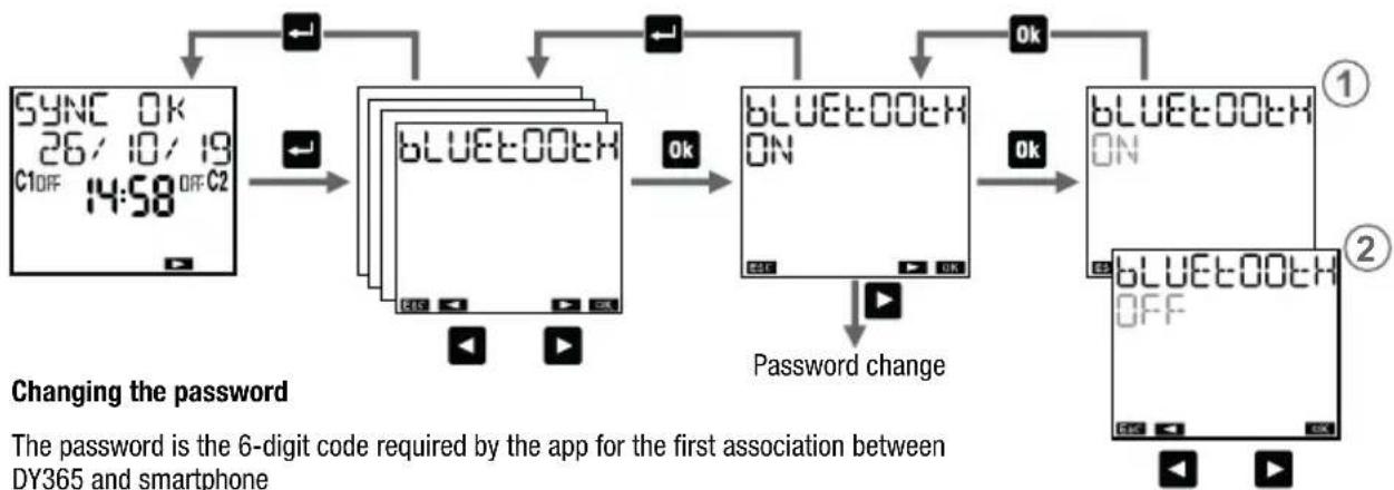
The Bluetooth menu allows you to enable or disable the Bluetooth interface and change the password used to associate your device (smartphone or tablet) to DY365.
The device is supplied with deactivated Bluetooth interface. To activate it, it's enough to access Bluetooth menu and set a password different from 000000. With Bluetooth menu it's possible to activate or deactivate the interface or change the password.
After changing the password the first time, it's not possible to set the value 000000.
To enable the Bluetooth interface:
① set Bluetooth ON
Warning: to make the Bluetooth interface active, the DY365 must be mains powered and connected to the main page (see page 8). The Bluetooth interface is therefore not active when browsing through the DY365 menus.
To disable the Bluetooth interface:
② set Bluetooth OFF
In this way no communication can take place between your device and DY365. DY365 works with the settings and programs already set; any changes or creation of new programs must be made by acting directly on the keyboard of DY365.
flowchart
graph TD
    A["SYNC 0K 26/10/19 C1OFF 14:58 OFF C2"] --> B["Switch"]
    B --> C["Bluetooth"]
    C --> D["OK"]
    D --> E["Bluetooth ON"]
    E --> F["OK"]
    F --> G["Bluetooth OFF"]
    G --> H["Change"]
    style A fill:#f9f,stroke:#333
    style B fill:#ccf,stroke:#333
    style C fill:#cfc,stroke:#333
    style D fill:#fcc,stroke:#333
    style E fill:#cff,stroke:#333
    style F fill:#ffc,stroke:#333
    style G fill:#fcc,stroke:#333
    style H fill:#ffc,stroke:#333
Changing the password
The password is the 6-digit code required by the app for the first association between DY365 and smartphone
① Press the key 📄 at least 3 seconds until the first digit of the password starts to flash.
⑬ Set the first digit with the keys ▶ and ▶ keys and press the key 📊 confirm and move to the next digit.
1c Repeat step 1 to set all 6 digits.
After confirming the last digit, the display shows the new password.
Press the key ↩ to exit the menu.

flowchart
graph LR
    A["1A PASSWORD 000000"] -->|3s| B["1B PASSWORD 000000"]
    B -->|OK| C["1C PASSWORD 123456"]
    style A fill:#f9f,stroke:#333
    style B fill:#f9f,stroke:#333
    style C fill:#f9f,stroke:#333
- 55 - User manual DY365
BUS MENU
DY365 enables you to control 8 independent channels but It has two relays (for channels 1 and 2). With additional DY365 4CE or DY365 2CE modules it's possible to add some relays and associate these relays to the channels of DY365. The remote actuators and DY365 all together are named "network".
"Bus" menu allows you to configure or to test the connection between DY365 and the actuators ①② or share programs among several DY365 connected to the network ③④.
① configure the outputs, to associate the channels of DY365 to the channels (relays) of the remote actuators
② to test the connection, to verify the correct association among the channels of DY365 and the channels (relays) of the actuators
③ to send programs to the other DY365 connected to the network
④ to receive the programs from another DY365 connected to the network

Note: during the configuration or channels test and during the reception of programs on the bus the switchings of all channels are disabled.

flowchart
graph TD
    A["SYNC 0K\n26/10/19\nC1OFF 14:58 OFF C2"] --> B["Bus"]
    B --> C["CONF OUT"]
    B --> D["TEST OUT"]
    D --> E["PRG SEND"]
    D --> F["PRG RECEP"]
    C --> G["..."]
    E --> H["OK"]
    F --> I["OK"]
Simple network configuration (one DY365, one or more remote actuators)
- On the remote actuator: activate "Channel configuration" mode (see the documentation supplied with the actuator)
- On the DY365:
2.1 Select-F OUT and confirm with on Y365 verifies the uniqueness of its address and when the test is successful it displays

2.2 Press to continue. Choose with the revs and the channel to configure of DY365
2.3 Press the key ok for at least 3 seconds. After configuration, the channel flashes (2 times) and the message appears.


flowchart
graph TD
    A["OK"] --> B["CONF OUT"]
    B --> C["AddR BUS CHECK"]
    C --> D["AddR BUS OK"]
    D --> E["CONF OUT"]
    E --> F["3s"]
    F --> G["CONF OUT DONE"]
    G --> H["CHANNEL 2"]
    C --> I["OK"]
    I --> J["CHANNEL 3"]
To delete the configuration of a channel, select the channel (steps 2.1 and 2.2) and press simultaneously for 3 seconds the keys ← and OK.
Complex network configuration (several DY365 one or more remote actuators)
About the configuration of the network in the case of several connected DY365, contact ABB Technical Support.
Connection test

flowchart
graph TD
    A["..."] --> B["tEST OUT"]
    B --> C["tEST OFF"]
    C --> D["CHANNEL 2"]
    C --> E["CHANNEL 3"]
    F["..."] --> G["tEST OUT ON"]
    G --> H["CHANNEL 2"]
    G --> I["CHANNEL 3"]
    J["..."] --> K["OK"]
    K --> L["ON"]
    L --> M["OFF"]
    M --> N["OK"]
    N --> O["ON"]
    O --> P["OFF"]
    P --> Q["OK"]
    Q --> R["ON"]
    R --> S["OFF"]
    S --> T["OK"]
    T --> U["ON"]
    U --> V["OFF"]
    V --> W["OK"]
    W --> X["ON"]
    X --> Y["OFF"]
    Y --> Z["OK"]
The test is used to verify proper communication between DY365 and the remote actuator. It's possible to test multiple channels simultaneously*.
During the test a series of on-off commands are sent every 5 seconds to the relay in test. It's possible to exit the test:
- by pressing the key ok to exit the test and test another channel
- by pressing the key → to exit the test and return to the main page
* See "Channels selection" on page 27
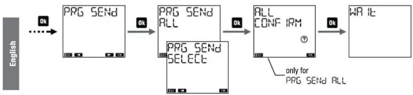
Programs copy on the bus
This function allows you to transfer programs from a DY365 to other DY365 connected to the same network. It's possible:
- to force the transfer to all other DY365 connected to the network (PRG SEND ALL)
- to transfer programs only to DY365 on which the reception mode* has been activated (PRG SEND SELECT
flowchart
graph LR
    A["PRG SEND"] -->|Ok| B["PRG SEND ALL"]
    B -->|Ok| C["ALL CONF IRM"]
    C -->|Ok| D["WRITE"]
    E["PRG SEND SELECT"] --> C
    F["only for PRG SEND ALL"] --> C
It's not possible to select the programs to copy, the entire memory area is copied. The programs previously stored on DY365 destination will be deleted.
⚠ Warning. The function PRG SEND ALL overwrites the programs of all DY365 connected to the network: use with caution.
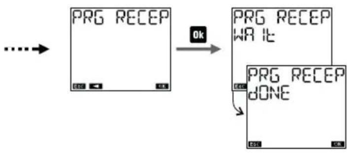
\* Reception programs on the bus
Activate reception mode (PRG RECEP) to receive the programs from another connected DY365 (that transmits programs via the function PRG SEND SELECT). The DY365 remains in reception for 1 minute and this condition is signaled from the flashingWA IE.
flowchart
graph TD
    A["PRG RECEP"] -->|OK| B["PRG RECEP WRITE"]
    A -->|OK| C["PRG RECEP DONE"]
In the case where the reception is not successful the message PRG RECEP ERROR is displayed.
Reception programs can take place at any time (even if the reception mode is not activated). This happens if another DY365 connected to the network transmits by using the function PRG SEND ALL.
SYNC MENU
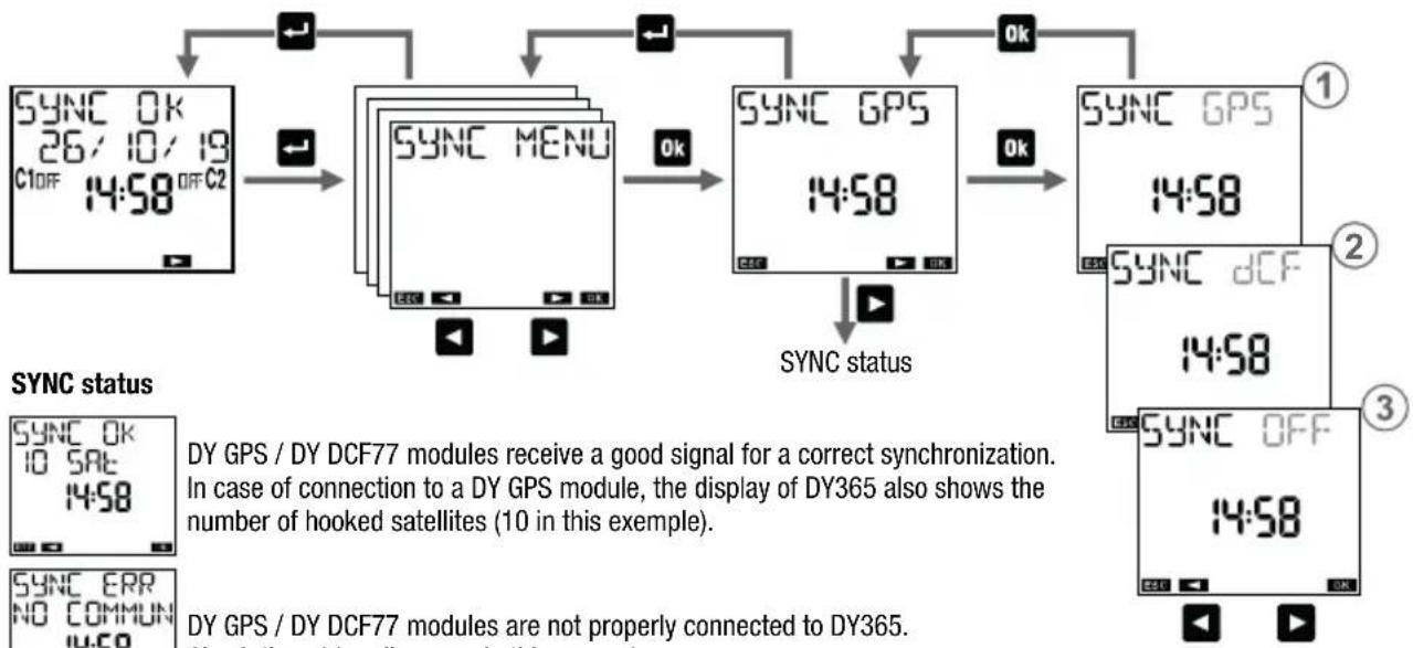
SYNC menu allows you to enable or disable the presence of the additional DY GPS or DY DCF77 modules. DY GPS allows you to capture the information of date, time and location from satellites and then to transfer them to DY365. DY DCF77 allows you to capture the informations of date and time. Both DY GPS and DY DCF77 are available as accessories. Synchronization occurs every 30 minutes. In this way the time of DY365 is always synchronized and there are no drifts due to the tolerance of the oscillator which marks the time base.
To enable the presence of DY GPS:
① set SYNC GPS
It's also possible to display the status of the connection to DY GPS (ok, waiting, error).
From the status page, while by pressing the key ok for at least 3 seconds it's possible to force data sending from DY GPS to DY365 (the display shows WRITE COMMUN ICA).
To enable the presence of DY DCF77:
② set SYNC dCF
It's also possible to display the status of the connection to DY DCF77 (ok, waiting, error).
From the status page, while by pressing the key OK for at least 3 seconds it's possible to force data sending from DY DCF77 to DY365 (the display shows WRITE COMMUNICA).
To disable the presence of DY GPS / DY DCF77:
③ set SYNC OFF
If DY GPS or DY DCF77 modules are not connected, it's advisable to set SYNC OFF to avoid displaying unnecessary information message SYNC ERR on the start page of DY365 (see page 8).
Note: the internal oscillator which marks the time base allows DY365 to maintain the updated time even without the presence of DY GPS / DY DCF77. In this case clock accuracy is ± 0.5 seconds per day.
- 02 - User manual DY365
flowchart
graph TD
    A["SYNC OK\n26/10/19\nC1OFF 14:58 OFF C2"] --> B["SYNC MENU"]
    B --> C["SYNC GPS\n14:58"]
    C --> D["SYNC GPS\n14:58"]
    D --> E["SYNC dCF\n14:58"]
    E --> F["SYNC OFF\n14:58"]
    F --> G["SYNCC status"]
    G --> H["SYNCC ERR\nNO COMM\n14:58"]
    style A fill:#f9f,stroke:#333
    style B fill:#ccf,stroke:#333
    style C fill:#cfc,stroke:#333
    style D fill:#fcc,stroke:#333
    style E fill:#cff,stroke:#333
    style F fill:#ffc,stroke:#333
    style G fill:#cfc,stroke:#333
    style H fill:#fcc,stroke:#333

DY GPS / DY DCF77 modules receive a good signal for a correct synchronization. In case of connection to a DY GPS module, the display of DY365 also shows the number of hooked satellites (10 in this example).
DY GPS / DY DCF77 modules are not properly connected to DY365. Check the wiring diagrams in this manual.
DY GPS / DY DCF77 modules do not receive a good signal for a correct synchronization. If this condition persists for more than a few hours, it's advisable to move DY GPS / DY DCF77 modules in a different position.
HOUR COUNTER MENU
“Hour counter” menu allows you to display the hours of use (relay on) of connected loads. The device has 8 counters, one for each channel. The maximum value of the counters is 99999 hours (about 11 years); reached the maximum limit, the counter resets automatically.
To reset a counter:
- select the desired channel
- press the key ok for 3 seconds until the display shows "HOUR CNE DELETE ?
- confirm by pressing Ok (press ←) exit without zeroing)
Note: it's possible to reset all counters contemporary from the "Reset" menu (see page 66).

flowchart
graph TD
    A["SYNC 0K<br>26/10/19<br>C1OFF 14:58 OFF C2"] --> B["↓"]
    B --> C["HOUR CNT"]
    C --> D["OK"]
    D --> E["HOUR CNT<br>0002 10h"]
    E --> F["3s"]
    F --> G["OK"]
    G --> H["HOUR CNT DELETE"]
    H --> I["CHANNEL ⑦"]
    I --> J["HOUR CNT<br>000053h"]
    J --> K["CHANNEL ②"]
    K --> L["HOUR CNT<br>0006 12h"]
    L --> M["CHANNEL ③"]
    M --> N["HOUR CNT<br>000004h"]
    N --> O["CHANNEL ⑤"]
- 65 - User manual DY365
RESET MENU
"Reset" menu allows you to restore the initial state of the device.
Available resets:
① Settings reset: deletes all the carried out settings (except the language, PIN and the channel settings on the BUS)
② Time programs reset: deletes all saved time programs
③ Holiday programs reset: deletes all saved holiday programs
④ Astro programs reset: deletes all saved astronomical programs
⑤ Counter reset: resets the counters of all channels
⑥ All reset: carries out all the above described resets and deletes the language, PIN protection and the channels settings on the bus
There is also another reset, of hardware type, which allows you to reset the device in case it responds to the pressing of the keys so unexpectedly, without losing the carried out settings/programs (only the date and the time are lost).
To carry out a hardware reset:
- press the key "R" with a sharp object

The hardware reset is also useful when you forget PIN protection. Reset, in fact, unlocks the keyboard for 3 minutes, the necessary time to access the appropriate menu and check/disable PIN.

flowchart
graph TD
    A["SYNC 0K<br>26/10/19<br>C1OFF 14:58 OFF C2"] --> B["RESET"]
    B --> C["OK"]
    C --> D["RESET SETT INGS"]
    D --> E["OK"]
    E --> F["RESET CONF IRM"]
    G["RESET PRG TIME"] --> H["RESET HOL IDAY"]
    H --> I["RESET PRG ASTRO"]
    I --> J["RESET HOUR CNT"]
    J --> K["RESET ALL"]
- 67 - User manual DY365
FIRMWARE MENU
This menu shows the firmware installed in the device, where:
022 is the revision index
05 is the month
20 is the day

flowchart
graph TD
    A["SYNC OK\n26/10/19\nC1OFF 14:58 OFF C2"] --> B["Output"]
    B --> C["VER FW\n022 05-20"]
    C --> D["Feedback to Sync"]
    D --> E["Arrow to C2"]
    E --> F["Arrow to C1OFF"]
ERROR SIGNALS
When setting up programs, in case of a discrepancy, the following error messages can occur:
ERROR 00: On and off events with different frequency (each on event must have an off event)
ERROR 002 On and off concomitant events of the same program
ERROR 003 Two or more consecutive on events of the same program / Two or more consecutive off events of the same program
ERROR 004 Invalid date
ERROR 005 Insufficient memory
ERROR 006 Attempt to set an on pulse on a channel where is already stored an off pulse (see page 27)
ERROR 007 Attempt to set an off pulse on a channel where is already stored an on impulse (see page 27)
ERROR 008 Attempt to set an on holiday program on a channel where is already stored an off holiday program (see page 27)
ERROR 009 Attempt to set a holiday off program on a channel where a holiday on program is already stored (see page 27)
ERROR 010 Attempt to set an annual program of on and off events on different days
ERROR 011 Attempt to set an astro program on a channel of time (see page 27)
ERROR 012 Attempt to set a time program on a channel of time type (see page 27)
ERROR 030 Error accessing memory *
* In this case, carry out a hardware reset (see page 66). If the error persists, contact ABB technical support
BATTERY MANAGEMENT
When the battery is close to empty, on the first line of the display appears battery. In this case, the battery must be replaced as soon as possible.
To replace the battery:
- remove the cover of battery compartment
- replace the battery with one of 3V CR14250 type and put the cover
In order not to lose the programming steps and carried out settings, it is necessary to ensure that the time for the battery replacement doesn't exceed 60 seconds (in absence of power by means).
REFERENCE STANDARDS
EU CONFORMITY DECLARATION
ABB declares that the device complies with the EU directive 2014/53/EU (RED) with reference to the following standards:
• EN 60730-2-7
• ETSI EN 301 489-1
• ETSI EN 301 489-17
• ETSI EN 300 328
The complete text of EU conformity declaration is available at the Internet address ABB - www.abb.com

Dispose of the used batteries observing the laws in force in relation to the disposal of hazardous waste.

ABB S.p.A
https://new.abb.com/low-voltage
© Copyright 2019 ABB S.P.A. All rights reserved.
We reserve the right to make technical changes
or modify the contents of this document without prior notice.
10-2020

- DIGITAL YEARLY TIME/ASTRONOMICAL SWITCH
- DY365
- User Manual
- Index
- TECHNICAL FEATURES
- SAFETY WARNINGS
- DIMENSIONS (mm)
- WIRING DIAGRAMS
- DY GPS / DY DCF77
- INITIAL OPERATION
- START PAGE (or main)
- Information messages
- Access the store of your device, install and start the free app DBT TIMER
- MENU DESCRIPTION
- SETTINGS MENU
- Daylight saving time (DST)/winter time (CET) change setting menu
- Astronomical coordinates setting menu
- Parameters modification
- To activate PIN protection:
- To disable PIN protection:
- Possible operations:
- Shortcut keys
- PROGRAM MENU
- Channels selection
- Select days
- Programs types
- Channel types
- Programs priority
- Priority list on/off
- Holiday program
- Program parameters
- How to select nights
- How to interpret the selection
- Night programs
- How to check a program
- How to modify or to delete a program
- BLUETOOTH MENU
- To enable the Bluetooth interface:
- To disable the Bluetooth interface:
- Changing the password
- BUS MENU
- Simple network configuration (one DY365, one or more remote actuators)
- Complex network configuration (several DY365 one or more remote actuators)
- Programs copy on the bus
- \* Reception programs on the bus
- SYNC MENU
- To enable the presence of DY GPS:
- To enable the presence of DY DCF77:
- To disable the presence of DY GPS / DY DCF77:
- HOUR COUNTER MENU
- To reset a counter:
- RESET MENU
- Available resets:
- FIRMWARE MENU
- ERROR SIGNALS
- BATTERY MANAGEMENT
- REFERENCE STANDARDS
Brand : ABB
Model : DY365
Category : Switch