
Q8 (2020) - Automobile AUDI - Free user manual and instructions
Find the device manual for free Q8 (2020) AUDI in PDF.


| Product Type | Automobile |
| Brand | Audi |
| Model | Q8 (2020) |
| Engine Options | Gasoline and diesel engines available |
| Transmission | 8-speed tiptronic automatic |
| Drive System | quattro all-wheel drive |
| Fuel Type | Gasoline or diesel (depending on market) |
| Fuel Tank Capacity | Approx. 22.5 gal (85 L) |
| Seating Capacity | 5 |
| Length | 198.1 in (5,032 mm) |
| Width | 78.8 in (2,001 mm) |
| Height | 67.1 in (1,705 mm) |
| Wheelbase | 117.9 in (2,995 mm) |
| Curb Weight | Approx. 4,900 lbs (2,222 kg) |
| Safety Systems | Airbags, ABS, ESC, Audi pre sense, parking aids |
| Infotainment | MMI touch displays, navigation, Audi connect |
| Climate Control | 4-zone automatic climate control |
| Steering | Electromechanical power steering |
| Brakes | Disc brakes, electromechanical parking brake |
| Maintenance | Service interval display, tire pressure monitoring |
| Battery | 12V lead-acid |
Frequently Asked Questions - Q8 (2020) AUDI
User questions about Q8 (2020) AUDI
0 question about this device. Answer the ones you know or ask your own.
Ask a new question about this device
Download the instructions for your Automobile in PDF format for free! Find your manual Q8 (2020) - AUDI and take your electronic device back in hand. On this page are published all the documents necessary for the use of your device. Q8 (2020) by AUDI.
USER MANUAL Q8 (2020) AUDI
natural_image
Four interlinked black rings logo (no text or symbols)Owner's Manual
2020 Q8
Foreword
Thank you for choosing an Audi – we value your trust in us.
Your new Audi will allow you to experience the best in groundbreaking technology and premium quality equipment that a vehicle has to offer. We recommend that you read your Owner's Manual thoroughly so that you quickly become acquainted with your Audi and make use of all of its features.
In addition to explaining how the different features work, we provide many useful tips and information concerning your safety, how to care for your vehicle, and how to maintain your vehicle's value. We also give you useful tips and information on how to drive your vehicle more efficiently and in an environmentally-friendly manner.
We hope you enjoy driving your Audi and we wish you safe and pleasant motoring.
AUDI AG

WARNING
Operating, servicing and maintaining a passenger vehicle or off-highway motor vehicle can expose you to chemicals including engine exhaust, carbon monoxide, phthalates, and lead, which are known to the State of California to cause cancer and birth defects or other reproductive harm. To minimize exposure, avoid breathing exhaust, do not idle the engine except as necessary, service your vehicle in a well-ventilated area and wear gloves or wash your hands frequently when servicing your vehicle. For more information go to www.P65Warnings.ca.gov/passenger-vehicle.
About this Owner's Manual..... 5
Summary 6
Quick access 6
Cockpit 6
Indicator lights overview 7
Display and operation.... 11
Instrument cluster 11
Instrument cluster overview ..... 11
Loading a personal profile.... 11
Operating 12
Adjusting the display 12
Coolant temperature display ..... 13
Tachometer 13
Odometer 14
Outside temperature display ..... 14
Engine oil temperature indicator ..... 14
Boost indicator 14
Shift light indicator 14
Sport displays 15
Vehicle functions 15
Touch displays 17
General touch display operation ..... 17
Multi Media Interface 19
Head-up display 25
Description 25
Voice recognition system.... 26
General information 26
Operating 26
External voice operation 27
Global functions 28
Additional function buttons 28
Starting and driving 29
Personalization 29
User 29
Opening and closing 31
Central locking 31
Keys 35
Luggage compartment lid 37
Child safety lock 41
Power windows 41
Panoramic glass roof 43
Lights and Vision 47
Exterior lighting 47
Interior lighting 50
Vision 51
Windshield wipers 53
Digital compass 56
Sitting correctly and safely ..... 58
Correct passenger seating position ..... 58
Front seats 58
Rear seats 61
Steering wheel 62
Head restraints 63
Safety belts 64
Memory function 67
Airbag system 68
Child safety seats 72
Stowing and using 78
Power sources 78
Cup holders 78
Storage and compartments 79
Luggage compartment 79
Roof rack 84
Warm and cold 87
Climate control system 87
Steering wheel heating 90
Fluids in the A/C system 90
Driving 92
Starting the vehicle 92
When driving 93
Drive system 99
Start/Stop system 100
Brakes 101
Electromechanical parking brake ..... 103
Special driving situations 104
Driving dynamic 108
Audi drive select 108
Suspension 109
Steering 111
Driving with a trailer 116
Assist systems 119
Assist systems 119
General information.... 119
Surrounding area detection ..... 120
Switching the systems on and off ..... 122
Driving information 124
Speed warning system 124
Camera-based traffic sign recognition ... 124
Traffic light information 126
Lap timer 127
Acceleration measurement 128
Night vision assist 129
Driver assistance 131
Cruise control system 131
Efficiency assist 132
Adaptive cruise assist 135
Distance warning 144
Lane departure warning 145
Audi pre sense 146
Side assist 151
Exit warning 153
Intersection assistant 154
Emergency assist.... 155
Parking and maneuvering ..... 157
Introduction 157
Parking aid plus 157
Rearview camera and peripheral cameras. 159
Rear cross-traffic assist 164
Infotainment system 166
Telephone 166
Introduction 166
Setup 166
Using the Audi phone box 168
Using the telephone 170
Messages.... 173
Settings 176
Instrument cluster 177
Troubleshooting 178
Audi connect 179
General information 179
Audi connect Infotainment 179
Using a Wi-Fi hotspot 180
Audi connect Infotainment services ..... 180
Audi connect vehicle control services .... 181
Settings 183
Troubleshooting 184
Emergency call 185
Overview 185
Emergency call 185
Online roadside assistance ..... 186
Navigation 188
Opening navigation 188
myAudi navigation 188
Entering a destination 189
Stopping route guidance 193
Map 194
Personal route assistance 196
Alternative routes 196
Additional functions 197
Satellite map 198
Map update 199
Traffic information 200
Options and settings 201
Radio 204
Opening the radio 204
Radio functions 205
Online radio 208
Options and settings 209
Troubleshooting 211
Media 212
General information 212
SD card reader 212
DVD drive 212
Bluetooth audio player 213
Online media 214
Amazon Alexa 215
Multimedia connections 215
Playing media 216
Options and settings 220
Supported media and file formats ..... 222
Troubleshooting 223
Audi smartphone interface ..... 224
Setup 224
Troubleshooting 225
Additional settings 226
System settings 226
Connected devices 227
Legal information 228
Maintenance and Care 230
Checking and Filling 230
Fuel 230
Refueling 231
Emissions control system 233
Engine compartment 234
Engine oil 236
Cooling system 240
Brake fluid 242
Electrical system 242
Battery 243
Windshield washer system 245
Service interval display 246
Wheels 247
Wheels and Tires 247
Tire pressure monitoring system ..... 265
If the Tire Pressure Monitoring System indicator appears 267
Care and cleaning 270
General information 270
Car washes 270
Cleaning and care information ..... 271
Taking your vehicle out of service ..... 275
Troubleshooting 276
Emergency assistance 276
General information 276
Equipment 276
Tire mobility kit 276
Replacing wheels 278
Collapsible spare tire 282
Jump starting 283
Towing 285
Fuses and bulbs 288
Fuses 288
Bulbs 292
Customer information 293
Data privacy 293
Image recording 293
Data memories 293
Transmitted information 294
Accessories and technical
changes 297
Warranty 297
Audi Literature Shop 297
Driving in other countries 297
Maintenance, repairs, and technical modifications 297
Accessories and parts 299
Reporting Safety Defects 299
Declaration of compliance for telecommunications equipment and electronic systems 300
Technical data 302
Identification data 302
Vehicle data 302
Index 304
This Owner's Manual applies to all versions of this model. It contains important information, tips, suggestions, and warnings for using your vehicle.
KEEP THIS GUIDE
Keep this manual and any other applicable documents in your vehicle at all times. This is especially important if you loan your vehicle to others or sell it.
This owner's manual describes the equipment range specified for this model at the time of printing. Individual equipment options described may only be available at a later date or may only be offered in certain countries.
Some sections in this manual do not apply to all vehicles. When this is the case, the beginning of the section indicates the validity, for example "Applies to: vehicles with speed warning system". Optional or vehicle-specific equipment is also identified with an asterisk "*".
The illustrations in this manual are a guide. Some of the details in your vehicle may differ from the illustration.
All directions, such as "left", "right", "front" and "rear", are based on the vehicle's direction of travel.
* Optional equipment or vehicle-specific equipment
The section continues on the next page.
⇒ ⚠️ Cross reference to a “WARNING” within a section. If a page number is indicated, the WARNING is located outside of the section.

WARNING
Text with this symbol contains information about safety and how to reduce the risk of serious personal injury or death.

Note
Text with this symbol contains information about reducing the risk of damage to your vehicle.

For the sake of the environment
Text with this symbol contains information on protecting the environment.

Tips
Text with this symbol contains additional useful information.
Quick access
Cockpit

Fig. 1 Cockpit
① Door handle
② Central locking switch 33
③ Memory function buttons ..... 67
④ Vent
⑤ Lever for:
– Turn signals and high beams .... 48
– High beam assistant ..... 48
– Lane departure warning ..... 145
– Lane guidance .... 139
⑥ Multifunction steering wheel with:
- Horn
- Driver's airbag 68
- Operating buttons 12, 28
- Shift paddles 96
⑦ Instrument cluster 11
⑧ Head-up display 25
⑨ Windshield washer system lever .. 53
⑩ Upper display 19
⑪ Lower display 19
⑫ Lockable glove compartment with:
- CD/DVD drive 212
⑬ Front passenger's airbag 68
⑭ Depending on equipment, buttons for:
– drive select 108
– Electronic Stabilization Control
(ESC) 114
– Emergency flashers 49
-Defrosting 87
– Rear window defogger ..... 87
⑮ MMI On/Off button 19,28
⑯ Depending on equipment, buttons for:
-Parking aid 157
– Driver assistance systems ..... 122
⑰ Depending on equipment:
- Starting the engine when there is a malfunction .... 93
-Cup holders 78
- Socket 78
– Vehicle key holder
⑱ Depending on equipment:
– Audi music interface ..... 215
-Audi phone box 168
- SD card reader 212
⑲ Electromechanical parking brake
button 103
20 Automatic transmission selector
lever 94
21 START ENGINE STOP
Steering wheel adjustment ..... 62
23 Lever for:
– Cruise control system ..... 131
- Adaptive cruise assist .... 135
②4 Connection port for the On Board
Diagnostic System (OBD) 293
25 Buttons for:
-Lights 47
- All-weather lights 47
②6 Hood release ....
27 Button for:
– Luggage compartment lid ..... 37
28 Exterior mirror adjustment .....
29 Buttons for:
- Power windows 41
-Child safety lock 41
i Tips
Some the equipment listed here is only installed in certain models or is available as an option.
Indicator lights overview
Description
The indicator lights in the instrument cluster blink or turn on. They indicate functions or malfunctions. Some warning and indicator lights turn on when you switch the ignition on and must turn off when the drive system is switched on or while driving.
With some indicator lights, messages may appear and warning signals may sound. The indicator lights and messages may be covered by other
displays. To show them again, select the second tab for messages with the multifunction steering wheel page 12.
Some indicator lights in the display can display in several colors.
⚠️ Central indicator light
If the ⚠ or ⚠ indicator light turns on, check the message in the instrument cluster.
Overview
The following indicator lights may be available, depending on the vehicle equipment:
Red indicator lights
| Central indicator light⇒ page 7,Instrument cluster⇒ page 11 | |
| Safety belt⇒ page 66 | |
| Engine start system⇒ page 93 | |
| Transmission⇒ page 98 | |
| Drive system⇒ page 100,Electrical system⇒ page 242 | |
| Electromechanical parking brake⇒ page 103 | |
| PARK | Electromechanical parking brake⇒ page 104 |
| Brake system⇒ page 102, ⇒ page 104,⇒ page 242 | |
| BRAKE | Brake system⇒ page 102, ⇒ page 104,⇒ page 242 |
| Steering⇒ page 111 | |
| Steering lock⇒ page 111 | |
| Air suspension⇒ page 110 | |
| Electrical system⇒ page 242 | |
| Engine oil level (MIN)⇒ page 237 | |
| Engine oil pressure⇒ page 236 | |
| Cooling system⇒ page 240 | |
| Hood⇒ page 235 | |
| Loose wheel warning⇒ page 262 | |
| Night vision assist⇒ page 130 | |
| Night vision assist⇒ page 130 | |
| Distance warning⇒ page 144 | |
| Steering intervention request⇒ page 140 | |
| Safe start monitor⇒ page 142,Driver intervention request⇒ page 142 | |
| Lane departure warning⇒ page 145 | |
| Lane departure warning⇒ page 145 | |
| Audi pre sense⇒ page 147,Intersection assist⇒ page 154 |
Yellow indicator lights
| Central indicator light⇒ page 7 | |
| Safety systems⇒ page 69 | |
| Transmission⇒ page 98 |
| Drive system⇒ page 100Cooling system⇒ page 240 | |
| Engine start system⇒ page 93 | |
| Keys⇒ page 93 | |
| Electromechanical parking brake⇒ page 104 | |
| Brake system⇒ page 102 | |
| Electronic Stabilization Control (ESC)⇒ page 113 | |
| Electronic Stabilization Control (ESC)⇒ page 113 | |
| ESC OFF | Electronic Stabilization Control (ESC)⇒ page 114 |
| ABS | Anti-lock braking system (ABS)⇒ page 115 |
| Anti-lock braking system (ABS)⇒ page 115 | |
| Steering⇒ page 111 | |
| Steering lock⇒ page 111 | |
| All wheel drive⇒ page 112 | |
| Suspension control⇒ page 110 | |
| Air suspension⇒ page 110 | |
| Active roll stabilization⇒ page 110 | |
| Engine speed limitation⇒ page 13 | |
| Tank system⇒ page 232 | |
| Electrical system⇒ page 242 | |
 | Engine oil level (MIN)⇒ page 237 |
 | Engine oil level (MAX)⇒ page 237 |
 | Engine oil sensor⇒ page 237 |
 | Malfunction Indicator Lamp (MIL)⇒ page 233 |
| Engine warm-up request⇒ page 237 | |
 | Washer fluid level⇒ page 246 |
 | Windshield wipers⇒ page 56 |
 | Parking aid⇒ page 158 |
 | Tire pressure⇒ page 265, ⇒ page 267 |
 |
| Loose wheel warning⇒ page 262 | |
| Bulb failure indicator⇒ page 50 | |
 | Adaptive light⇒ page 50 |
 | Light/rain sensor⇒ page 50, ⇒ page 56 |
| Door lock⇒ page 33 | |
 | Battery in vehicle key⇒ page 37 |
 | Night vision assist⇒ page 130 |
 | Intersection assistant⇒ page 154 |
| Side assist⇒ page 152;Exit warning⇒ page 153 | |
| Rear cross-traffic assist⇒ page 164 |
 | Adaptive cruise assist page 143 |
 | Steering intervention request page 140, page 146 |
 | Lane departure warning page 146 |
 | Distance warning page 144 |
 | Audi pre sense page 150 |
 | Emergency assist page 155 |
 | Emergency call function page 186 |
Other indicator lights
| Rear safety belt page 66 | |
| Start/Stop system page 100 | |
| Hill descent assist page 106 | |
| Low beam headlight page 47 | |
| Parking light page 47 | |
| Turn signals page 48, page 49 | |
| CRUISE | Cruise control system page 131 |
| Cruise control system page 131 | |
| Efficiency assist page 132 | |
| 50 | Efficiency assist page 132 |
| Efficiency assist page 132 | |
| Efficiency assist page 132 | |
| Efficiency assist page 132 | |
 | Adaptive cruise assist⇒ page 137 |
| [CCSY] | Adaptive cruise assist⇒ page 137 |
| [KX83] | Adaptive cruise assist⇒ page 137 |
| [E3HD] | Adaptive cruise assist⇒ page 137 |
 | Lane guidance for adaptive cruise assist⇒ page 137 |
| [OKT6] | Lane departure warning⇒ page 145 |
 | High beams⇒ page 48 |
 | High beam assistant⇒ page 48 |
| [460W] | Rear safety belt⇒ page 66 |
| [02ZZ] | Rear safety belt⇒ page 66 |
| [8ZZA] | Transmission⇒ page 98 |
 | Convenience key⇒ page 93 |
 | Electromechanical parking brake⇒ page 104 |
 | Electromechanical parking brake⇒ page 104 |
 | Hill descent assist⇒ page 106 |
 | Air suspension⇒ page 110 |
 | Parking aid⇒ page 158 |
| [84W4] | High beam assistant⇒ page 48 |
| [8HAJ] | Door lock⇒ page 33 |
 | Child safety lock page 41 |
 | |
 | Speed warning system page 124 |
 | Speed warning system page 124 |
 | Camera-based traffic sign recognition page 125 |
 | Night vision assist page 130 |
 | Cruise control system page 131 |
 | Cruise control system page 131 |
 | Intersection assistant page 154 |
 | Side assist page 152 |
 | Distance warning page 144 |
 | Rear cross-traffic assist page 164 |
 | Adaptive cruise assist page 143,Efficiency assist page 134 |
| [444X] | Adaptive cruise assist page 140 |
 | Lane guidance for adaptive cruise assist page 137 |
 | Lane departure warning page 145 |
 | Lane departure warning page 146 |
 | Audi pre sense page 150 |
 | Emergency assist page 155 |
Instrument cluster
Instrument cluster overview
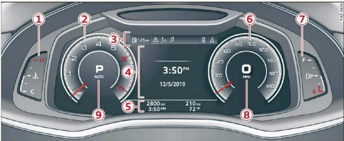
Fig. 2 Instrument cluster overview (Audi virtual cockpit)
Depending on the vehicle equipment, the following items may appear in the instrument cluster:
① Display
- Engine coolant temperature ≈ .. 13
② Left dial
- Tachometer 13
③ Tab area 12
④ Central area 12
⑤ Status line (one or two lines)
⑥ Right dial
- Convenience display
⑦ Fuel level 232
⑧ Right additional display with speedometer
⑨ Left additional display with:
- Gear .... 94
- Audi drive select mode .... 108
! WARNING
If there is a severe malfunction in the instrument cluster, the display may turn off. The indicator light may also turn on. Stop the vehicle safely. See an authorized Audi dealer or authorized Audi Service Facility for assistance.
i Tips
- You can select the units used for temperature, speed, and other measurements in the Infotainment system page 226.
- Speeds are displayed in mph (miles per hour) or km/h (kilometers per hour).
- If there is a malfunction in the instrument cluster, DEF will appear in the trip odometer display. Have the malfunction corrected as soon as possible.
- Certain instrument cluster content can also be displayed in the head-up display* ⇒ page 25.
- Certain settings are stored automatically in the active personal profile.
Loading a personal profile
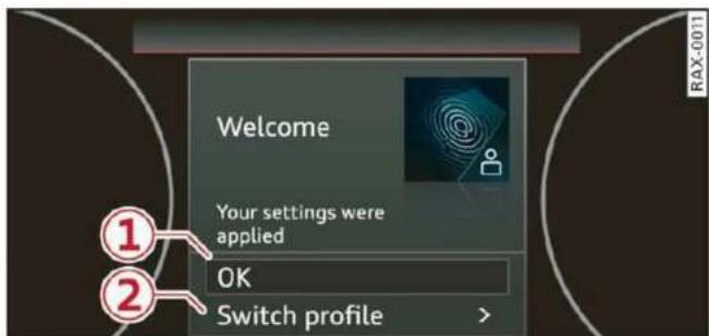
Fig. 3 Instrument cluster: loading a personal profile
You can manage personal profiles in the MMI page 29. Before driving, you can select your personal profile in the instrument cluster and apply customized vehicle settings, such as the seat position.
Requirement: the driver's door must have been opened and the ignition must not be switched on.
▶ Confirm the displayed profile ①, or
▶ To load another profile, select and confirm Switch profile ②.
▶ Select and confirm the desired profile. The user-specific settings will load.
▶ To cancel the seat, mirror, and steering column adjustment, select Cancel.

Tips
For more information and usage options for personal profiles, see page 29.
Operating

Fig. 4 Instrument cluster: driver information system

Fig. 5 Left side of multifunction steering wheel
Information is organized within various tabs ① in the instrument cluster. The tab contents are displayed in the central area ②.
Requirement: the ignition must be switched on.
Selecting a tab
▶ Press the ◀/▷ button ③ repeatedly until the desired tab is selected.
Returning to functions at higher levels
▶ Press the ↩ button ⑤.
Opening and closing the menu
▶ Press the ≡ button ⑥.
Selecting and confirming a function
Requirement: a menu or list must be displayed.
▶ To select a function, turn the left thumbwheel
⑦ to the desired function.
▶ To confirm a selection, press the left thumbwheel ⑦.
Switching the view
▶ Press the VIEW button ④.
The following tabs may be available, depending on vehicle equipment:
| First tab | Vehicle functions ⇒ page 15 |
| Second tab | Driver messages (this is only displayed if at least one indicator light/message is being displayed) |
| Third tab | Night vision assist (this is only displayed if the night vision assist has been activated) ⇒ page 129 |
| Fourth tab | Radio ⇒ page 204 |
| Media ⇒ page 216 | |
| Fifth tab | Telephone ⇒ page 177 |
| Sixth tab | Navigation ⇒ page 188 |
Adjusting the display
flowchart
graph TD
    A["①"] --> B["②"]
    B --> C["③"]
    style A fill:#f9f,stroke:#333
    style B fill:#ccf,stroke:#333
    style C fill:#cfc,stroke:#333
Fig. 6 Upper display: adjusting the display
Switching the view
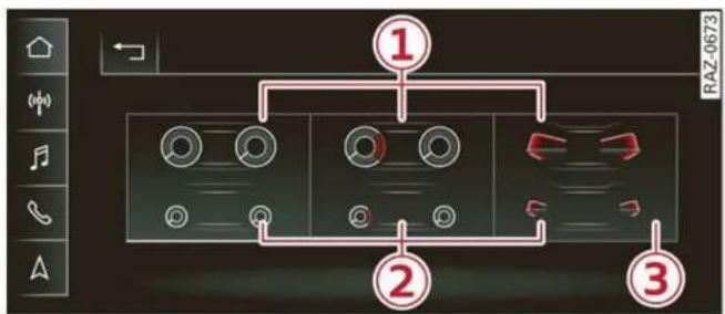
▶ Press the VIEW button to switch between the default view ① and the enhanced view ②.
Adjusting the layout
Depending on the vehicle equipment, various layouts may be available.
- Applies to: MMI: Select on the home screen: SETTINGS > Display & brightness > Virtual cockpit. - To adjust the desired layout, press ③.
Setting the automatic layout change
Applies to: RS models
Requirement: the RS Performance layout must be selected.
Applies to: MMI: Select on the home screen: SETTINGS > Display & brightness > Virtual cockpit > Configure > Automatic activation of RS layout.
When the function is switched on, the system will automatically set the RS Performance layout when you switch to the RS modes page 108.
Adjusting the additional display
Depending on the vehicle equipment, the additional displays that can be selected may vary.
- Applies to: MMI: Select on the home screen: SETTINGS > Display & brightness > Virtual cockpit > (Configure). - Select the desired additional display.
Reducing the display
Depending on the vehicle equipment, you can hide the central area in the instrument cluster.
▶ Select in the instrument cluster: vehicle functions tab > ☐ button > Reduced display.
Coolant temperature display
The coolant temperature display ① page 11 only functions when the ignition is switched on. To reduce the risk of engine damage, please observe the following notes about the temperature ranges.
Cold range
If only the LEDs at the bottom of the gauge turn on, the engine has not reached operating temperature yet. Avoid high engine speeds, full acceleration, and heavy engine loads.
Normal range
The engine has reached its operating temperature once the LEDs up to the center of the gauge turn on. If the indicator light in the instrument cluster display turns on, the coolant temperature is too high page 240.

Note
- Auxiliary headlights and other accessories in front of the air intake impair the cooling effect of the coolant. This increases the risk of the engine overheating during high outside temperatures and heavy engine load. - The front spoiler also helps to distribute cooling air correctly while driving. If the spoiler is damaged, the cooling effect will be impaired and the risk of the engine overheating will increase. See an authorized Audi dealer or authorized Audi Service Facility for assistance.
Tachometer
The tachometer ② page 11 displays the engine speed in revolutions per minute (RPM). The beginning of the red zone in the tachometer indicates the maximum permissible engine speed for all gears once the engine has been broken in. Before reaching the red zone, you should shift into the next higher gear, select the "D" or "S" selector lever position, or remove your foot from the accelerator pedal.
Engine speed limitation
If the indicator light turns on, the engine will be automatically limited to the RPM displayed in the instrument cluster. This will protect the engine components, for example during a cold start or from overheating.
The engine speed limitation will be deactivated once the engine has reached its normal operating ▶
temperature and you have released the accelerator pedal.
If the engine speed limitation was activated by an engine control malfunction, the indicator light also turns on. Make sure the engine speed does not go above the speed displayed, for example when downshifting. Drive to an authorized Audi dealer or authorized Audi Service Facility immediately to have the malfunction corrected.

Note
The needle in the tachometer may only be in the red area of the gauge for a short period of time before there is a risk of damaging the engine. The location where the red zone begins varies depending on the engine.
Odometer
The trip odometer and odometer are displayed in the status line ⑤ ⇒ page 11.
The trip odometer shows the distance driven since it was last reset. It can be used to measure short distances. The odometer shows the total distance that the vehicle has been driven.
Resetting the trip odometer
▶ Select in the instrument cluster: vehicle functions tab > ☐ button > Reset mi.

Tips
Distances are displayed in mi (miles) or km (kilometers).
Outside temperature display
The outside temperature is displayed in the status line ⑤ ⇒ page 11.
If your vehicle is stationary or if you are driving at very low speeds, the temperature displayed in the instrument cluster may be slightly higher than the actual temperature outside due to heat radiating from the engine.
At temperatures below 41 °F (+5 °C), a snowflake symbol appears in front of the temperature display ⇒ ⚠.

WARNING
Do not assume the roads are free of ice based on the outside temperature display. Be aware that there may be ice on roads even when the outside temperature is around 41 °F (+5 °C) and that ice can increase the risk of accidents.
Engine oil temperature indicator
Depending on the vehicle equipment, the engine oil temperature may be indicated by a bar in the instrument cluster.
▶ Open the vehicle functions tab and switch to the enhanced view page 12.
When engine oil temperatures are low, the display --- °F (--- °C) appears in the instrument cluster. The engine has reached its operating temperature when the engine oil temperature is between 176 °F (80 °C) and 248 °F (120 °C) under normal driving conditions. The engine oil temperature may be higher if there is heavy engine load and high temperatures outside. This is not a cause for concern as long as the ⇒ page 236 or ⇒ page 237 indicator lights do not turn on.
Boost indicator
Applies to: vehicles with boost indicator
Depending on vehicle equipment, the current engine load (meaning the current boost pressure) may be indicated by a bar in the instrument cluster.
▶ Open the vehicle functions tab and switch to the enhanced view page 12.
Shift light indicator
Applies to: RS models
The shift light indicator informs the driver when the rpm limit is reached.
▶ Set the RS Performance layout page 12.
The shift light indicator is displayed with green, yellow and red ranges in the upper areas of the tachometer. The shift light indicator will blink red when approaching the engine speed limit. Shift to the next highest gear at the right time.
Sport displays
Applies to: RS models
Various sport displays, such as a G meter or tire pressure indicator, may be available depending on vehicle equipment.
Opening sport displays in the instrument cluster
▶ Select in the instrument cluster: vehicle functions tab > ☐ button > Sport displays.
▶ Turn the left thumbwheel on the multifunction steering wheel until the desired sport display appears in the instrument cluster.
Opening sport displays in the MMI
▶ Applies to: MMI: Select on the home screen: VEHICLE > RS monitor.
▶ Browse to the desired display if necessary.
G meter
The G meter displays the longitudinal and lateral acceleration. The current values are displayed in the instrument cluster while driving. The maximum values that are reached are stored and displayed when the vehicle is stationary. Only the maximum values that are reached are displayed in the MMI.
▶ To reset the stored values, press and hold the left thumbwheel on the multifunction steering wheel for one second.
Tire pressure
The tire pressure monitoring system displays the current tire pressures and temperatures. Also see page 267, If the Tire Pressure Monitoring System indicator appears.
Engine data
The engine data in the instrument cluster shows which percentage of the maximum output or maximum torque is currently being used.
Temperature
The temperature display in the MMI shows the temperature of various fluids and vehicle components, such as the engine oil or sport differential.
Inclinometer
The inclinometer in the MMI shows the sideways and lengthwise angle of the vehicle in relation to the horizon. It shows both the current values and the maximum values that were reached ⇒ page 105.
Vehicle functions
Overview
The trip computer is displayed in the first tab of the driver information system. Additional vehicle functions can be accessed depending on the vehicle equipment.
- Press the ☐ button on the multifunction steering wheel.
- On-board computer page 15
- Reduced display page 13
- Reset trip odometer page 14
– Sport displays page 15
– Lap times page 127
– Lap statistics page 128
-Acceleration measurement page 128
On-board computer
Resetting values to zero
Requirement: the Consumption, Short-term memory, or Long-term memory display must be selected.
▶ To reset the values in one of the memories to zero, press and hold the left thumbwheel on the multifunction steering wheel for one second, or
▶ Select in the instrument cluster: vehicle functions tab > ☐ button > Reset mi.
Depending on the vehicle equipment, you can call up the following displays in the on-board computer one at a time by turning the left thumb-wheel on the multifunction steering wheel:
– Time and date page 226
– Average consumption page 16
– Short-term memory overview
- Long-term memory overview
– Energy consumers page 16
– Driver assistance
– Traffic sign recognition and traffic light information
Short-term memory and long-term memory
The short-term memory collects driving information from the time the ignition is switched on until it is switched off. If you continue driving within two hours after switching the ignition off, the new values will be included when calculating the current trip information.
Unlike the short-term memory, the long-term memory is not erased automatically. You can select the time period for evaluating trip information yourself.
Average consumption
The current consumption can be shown using a bar graph. The average consumption stored in the short-term memory is also displayed. If the bar is green, your vehicle is saving energy (for example, using recuperation).
Energy consumers
The Energy consumers view lists other equipment that is currently affecting fuel consumption. The display shows up to three equipment items. The equipment using the most power is listed first. If more than three items using power are switched on, the equipment that is currently using the most power is displayed. A gauge also shows the current total consumption of all other equipment.

Tips
The date, time of day, and time and date format can be set in the Infotainment system page 226.
Touch displays
General touch display operation
General information
Applies to: touch displays
The touch display is controlled through the touchscreen. Operation is very similar to operating a smartphone.
All touch displays in the vehicle can be operated with the gestures described in the following information.

Tips
Certain gestures may not be available on all touch displays or in every menu.
Pressing
Applies to: touch displays
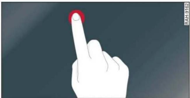
natural_image
Illustration of a hand with a red circular button on a finger, against a dark background (no text or symbols)Fig. 7 Touch display: pressing
Selecting a function or button
▶ Press the desired function or button.
Pressing and holding
Applies to: touch displays

natural_image
Hand with finger icon pressing a red circular button (no text or symbols)Fig. 8 Touch display: pressing and holding
Accessing options
For some items, you can access additional options that are not directly visible.
▶ Press and hold an item until the associated options are displayed.
Pressing and pulling
Applies to: touch displays
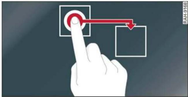
Fig. 9 Touch display: pressing and pulling
Moving an item
You can position some items at any location on the screen.
▶ Press and hold an item, and then use your finger to pull it to the desired location.
Pinching fingers together and pulling apart
Applies to: touch displays
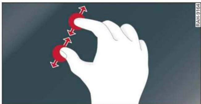
natural_image
Illustration of a hand holding two red circular objects with directional arrows indicating movement (no text or symbols)Fig. 10 Touch display: pinching fingers together and pulling them apart
Zooming in and out on an item
▶ To increase the size of an item, touch it with two fingers and pull your fingers apart.
▶ To decrease the size of an item, touch it with two fingers and pull your fingers together.
Rotating
Applies to: touch displays

natural_image
Hand holding a red circular button with a curved arrow, symbolizing rotation or refresh (no text or symbols present)Fig. 11 Touch display: rotating
Rotating the view or perspective
▶ Rotate the item using two fingers.
Dragging
Applies to: touch displays
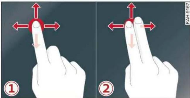
Fig. 12 Touch display: ① dragging with one finger, ② dragging with two fingers
Scrolling or browsing through menus/lists
▶ To scroll through menus and lists, swipe upward or downward with one finger.
▶ To browse through menus and lists, swipe to the right or left with one finger.
Tilting 3D displays
- Drag upward or downward with two fingers.
Dragging away from/toward the edge of the screen
Applies to: touch displays

natural_image
Hand pointing at a red circular button with a downward arrow, no text or symbols presentFig. 13 Touch display: dragging away from the edge of the screen
Opening hidden menus
The ☐ symbol indicates that there is a hidden menu.
▶ Use your finger to drag inward from the upper or lower edge of the screen, or
▶ Press the — button.
Closing hidden menus
▶ Press within the menu and drag it toward the upper or lower edge of the screen.
Information about menu paths
This guide shows you at a glance the paths for opening a desired menu and its settings and functions.
Example of a path
Applies to: MMI: Select on the home screen: SETTINGS > General > Date & time.
Following the path
▶ First, determine in which display the path should be entered. In this example, it is the MMI display.
- Applies to MMI: To open the home screen, press ⬇.
▶ If the SETTINGS button is not displayed, use your finger to swipe to the left or right until it appears.
▶ Press the SETTINGS button.
▶ If the General button is not displayed, swipe toward the left or right with one finger until it appears.
▶ Press the General button.
▶ If the Date & time button is not displayed, swipe upward or downward with one finger until it appears.
▶ Press the Date & time button.

Tips
If a menu or symbol is in parentheses in the path, for example, (General) or (○), then it is an optional menu item that does not need to be used in every system.
Settings
You can adjust or turn off the MMI touch display feedback.
▶ Applies to MMI: Select on the home screen: SETTINGS > Display & brightness > MMI.
Possible settings:
- Brightness
- Touchscreen Feedback
Multi Media Interface
Traffic safety information
Audi recommends performing certain Infotainment system functions, such as entering a destination, only when the vehicle is stationary. Always be prepared to stop operating the Infotainment system in the interest of your safety and the safety of other road users.

WARNING
Only use the Infotainment system when road, traffic, weather, and visibility conditions permit and always in a way that allows you to maintain complete control over your vehicle.

Tips
Certain functions are not available while driving.
Switching on or off
Switching the MMI on or off
▶ To switch the MMI off, press and hold the On/Off knob page 28, fig. 20 until the upper display and all Infotainment system functions are switched off.
▶ To switch the MMI on, press the On/Off knob.
Restarting the MMI
- Press and hold the On/Off knob for at least 10 seconds.
Switching displays on or off
▶ To switch the upper display off, press ☐ on the lower display.
▶ To switch the upper display on, touch the upper display or press ☐ on the lower display.
▶ To switch both displays on or off, press and hold ☐ on the lower display.
Introduction
You can display and operate Infotainment system and vehicle functions using both of the Multi Media Interface (MMI) touch displays.
Configuration wizard
After starting for the first time, the configuration wizard helps you to set up the vehicle, for example to set the desired system language and connect a telephone.
▶ Follow the instructions in the display.
Applies to: MMI: To access the configuration wizard at a later time, select on the home screen: HELP > Configuration wizard.
Tool tips
Tool tips are displayed on the upper display after starting for the first time. They introduce various MMI functions to you.
▶ Follow the instructions in the display.
▶ Applies to: MMI: To access the tool tips at a later time, select on the home screen: SETTINGS > Help > Show tool tips.
Applies to: MMI: To receive additional tool tips, select on the home screen: HELP > Tool tips > Basic information or Expert information.
Menus and symbols

Fig. 14 Upper/lower display: home screen
| Label | Description | |
| 1 | Quick access bar | Return to the home screen or open a menu quickly ⇒ page 20 |
| 2 | Status bar | Displays existing notifications 7 ⇒ page 21, status display 8 ⇒ page 21, time |
| 3 | Display area | Select a menu, apply settings, display content ⇒ page 21 |
| 4 | Function bar | Activate functions or access attached content ⇒ page 22 |
| 5 | Shortcuts | Using shortcuts ⇒ page 22 |
| 6 | Climate control settings | Adjust the climate control system settings ⇒ page 87 |
Description of common symbols
You can operate the default functions using the symbols that follow. The symbols may be found in any menu, depending on the context.
| Symbol | Description |
| Go back one level | |
| Close the menu | |
| Search for content | |
| Open explanations for a menu | |
| Open settings for the selected menu | |
| Open the submenu | |
| Adjust the settings | |
| Set as favorite | |
| Switch functions on or off | |
| Switch functions on or off | |
| Switch functions on or off |
| Symbol | Description |
| ... | Open additional actions |
| > | Open additional information for the selected menu |
i Tips
The following pages primarily show Illustrations of the upper display with the largest possible screen size. The display or location of the items shown may vary depending on the vehicle equipment.
Quick access
With quick access, you can return to the home screen and quickly switch between four menus that can be individually configured.
Returning to the home screen or opening a menu quickly
▶ Press ⬇ or one of the four buttons.
Configuring quick access
▶ Press and hold a button on the home screen display area or in the quick access bar.
▶ To move a button to the quick access bar, pull it from the display area to the quick access bar.
▶ To adjust the placement of the buttons in the quick access bar, pull them to the desired position in the bar.
▶ Press Done to complete the configuration.

Tips
The position of ⬆ cannot be adjusted.
Display area
You can freely change the location of the buttons on the home screen display area.
Configuring the display area
▶ Press and hold a button on the home screen display area.
▶ To adjust the placement of the buttons, pull them to the desired locations.
▶ Press Done to complete the configuration.
Switching between menu pages
If a menu contains multiple menu pages, —— is displayed in the display area. The white bar shows the location of the current menu page.
▶ To switch between menu pages, swipe your finger to the right or left.
Status display

Fig. 15 Upper display: common symbols in the status bar
The symbols in the status bar show you information at a glance, such as if a mobile device is connected or if there is a data connection. The most common symbols are listed in the table.
| Description | |
| 1 | There is a data connection. The bar indicates the signal strength of the data connection. Data is being transmitted now. |
| 2 | There is a data connection. The bar indicates the signal strength of the data connection. No data is being transmitted now. |
| 3 | A mobile device is connected. The bar indicates the signal strength of the cell phone connection. |
| 4 | There is no data connection. |
| 5 | An error occurred with the mobile device connection to the MMI. |
| 6 | The personal profiles are switched on. The digits 1 - 6 indicate which personal profile is currently active. The guest profile is active if there are no digits. |
| 7 | A Bluetooth device is connected. |
| 8 | Bluetooth is switched on, but no Bluetooth device is connected. |
| 9 | Audio playback was interrupted. |
| 10 | The audio source is muted. |
| 11 | Privacy settings are enabled. The additional symbol indicates which privacy settings are currently activated ⇒ page 294. |
Notification center

Fig. 16 Upper display: notification center
Notifications can be displayed in the upper display. After a specified time, they will be hidden and a corresponding symbol will appear in the status bar ⑦ ⇒ page 20, fig. 14. In the notification center, you can view these notifications ② ⇒ fig. 16 and apply quick settings ①.
Using the notification center
▶ To open the notification center, pull the status bar downward, or
▶ Press the — button on the status bar.
▶ To apply quick settings, press the respective symbol ①.
▶ To obtain additional information about a notification, press it.
▶ To delete a notification, pull it toward the right edge of the screen.
▶ If there are more than four notifications in the notification center, the older notifications will be hidden. To display the older notifications, drag your finger upward on the screen.
Setting displayed content
You can set whether some notifications should be displayed.
▶ To set the displayed content, press 📄, or
▶ Applies to MMI: Select on the home screen:
SETTINGS > Notifications.
▶ Select and confirm which notifications should be displayed.
Possible quick settings
| Symbol | Description |
| Apply sound settings | |
| Open menu settings | |
| Manage connected devices | |
| Manage personal profiles | |
| 9/4/2017 | Set date and time |
| Set displayed content in the notification center |
Function bar
Depending on the vehicle equipment, you can operate various functions in the function bar.
| Symbol | Description |
| OFF | Switch Start/Stop system on or off |
| Switch hill descent assist on or off |
| Symbol | Description |
| Opens the garage door opener function | |
| Press: shows settings for the head-up display | |
| Press and hold: switches the head-up display on or off | |
| Press: switches the upper display on or off | |
| Press and hold: switches both displays on or off |
Shortcuts
By creating shortcuts, you have quick access to various items, such as radio stations, frequently used contacts, or vehicle settings.
Adding shortcuts
The … buttons in the upper display indicate, for example, if a selected radio station can be added to the shortcuts. Depending on the context, you may also be able to add items from a list to the shortcuts.
▶ Press … or press and hold an item in a list.
▶ Press Save as a shortcut. The selected item will be added to the shortcuts on the lower display and displayed as a tile.
Using shortcuts
▶ Press the ☐☐☐④ ⇒ page 20, fig. 14 button in the function bar on the lower screen. The saved shortcuts will be displayed or hidden.
▶ To access the stored function, press the respective tile.
Moving or deleting shortcuts
▶ Press and hold a shortcut on the lower display.
▶ To adjust the order of the shortcuts, drag a shortcut to the desired location.
▶ To delete a shortcut, press Ⓧ.
Text input

Fig. 17 Upper/lower display: text input
In the input fields of various menus, you can enter letters, numbers and characters, for example to find an address in navigation.
On the lower section of the screen, you can enter the text with handwriting or using the on-screen keyboard. The current text input is displayed on the upper section of the screen ①. Depending on the context, word suggestions may be given based on the characters that have been entered ② and a results list may be shown ③.
Opening text input
▶ Press in the input field ①.
Switching input languages
Requirement: multiple input languages must be defined in the MMI page 24.
▶ To switch between the defined input languages, press the button ⑧.
Switching the input methods
▶ To switch between handwriting input or the on-screen keyboard, press the button ⑦.
Entering text
Applies to: handwriting input: To enter text, simply write in the input area using one finger ⑥. You can write the separate characters next to each other or one on top of the other with-
out having to move your finger over after writing a character. When you end the entry, the writing is interpreted by the system.
Applies to: the on-screen keyboard: To enter text, press the buttons on the keyboard. Depending on the usage context, you may also be able to swipe over the letters 1).
Applies to: the on-screen keyboard with an input language that uses accented characters: To enter accented characters (such as â, ç, ñ, ö), press and hold a character that has accented versions available and select the desired accented character.
Applies to: handwriting input: To enter a space, drag a line from left to right in the input section ⑥.
▶ To select a location in the text input, press on the desired location in the input field. You can control the location more accurately using the displayed slider ⑤.
▶ To delete individual characters, press ✕ ④, or
Applies to: handwriting input: Drag a line from right to left in the input section ⑥.
▶ To delete multiple characters, press and hold ✕ ④.
▶ To delete all characters in a specific location, press and hold ☒④ and drag up to the desired location 1) . When released, the highlighted characters are deleted.
Accepting suggested words or selecting entries from the results list
To accept a suggested word ② or select an entry from the results list ③, press on it.
▶ To display more content in the results list, drag your finger upward or downward on the screen.
Setting the input language or keyboard layout
▶ Applies to MMI: Select on the home screen: SETTINGS > Language & keyboard > Keyboard.
▶ To define additional input languages, press the ⏻ button.
▶ To change the keyboard layout for an input language, press >. For example, you can select between OWERTZ and OWERTY.
Head-up display
Description
Applies to: vehicles with head-up display
The head-up display projects certain warnings or selected information from the assist systems on the windshield. The display appears within the driver's field of vision.
Switching on and off
The button is located in the function bar on the lower display page 20.
▶ To switch the head-up display on or off, press and hold the ⏻ button.
Settings in the Infotainment system
▶ Applies to: MMI: Select on the home screen: SETTINGS > Display & brightness > Head-up display, or
▶ Press the 🔊 button.
Possible settings:
– Picture rotation
- Brightness
- Display height: you can adjust the height of the display. Sit in the correct seating position page 58 and adjust the head-up display.
- Display contents: you can set which information should be displayed. The display of certain information and some of the red indicator lights cannot be hidden.
Note
To reduce the risk of scratches on the glass covering the head-up display, do not place any objects in the projection opening.
i Tips
– Sunglasses with polarization filters and unfavorable lighting conditions can impair visibility of the display.
- An optimal display depends on the seat position and the height adjustment of the head-up display.
- A special windshield is needed for the head-up display function.
- For information on cleaning, see table Interior cleaning on page 272.
- Certain settings are stored automatically in the active personal profile.
Voice recognition system
General information
Applies to: vehicles with voice recognition system
You can operate many functions in the vehicle easily using voice commands.
Using the voice recognition system optimally
▶ Speak clearly and distinctly at a normal volume. Speak louder when driving faster.
▶ Emphasize the words in the commands evenly and do not leave long pauses.
- Close the doors, the windows, and the sunroof* to reduce background noise. Make sure that passengers are not speaking when you are giving a voice command.
▶ Do not direct the vents toward the hands-free microphone, which is in the roof headliner near the front interior lights.
▶ Only the driver should speak to the system, because the handsfree microphone is aimed toward this seating position.

WARNING
- Direct your full attention to driving. As the driver, you have complete responsibility for safety in traffic. Only use the functions in such a way that you always maintain complete control over your vehicle in all traffic situations.
- Do not use the voice recognition system in emergencies because your voice may change in stressful situations. The system may take longer to dial the number or may not be able to dial it at all. Dial the emergency number manually.

Tips
There are no voice guidance* prompts when a dialog is active.
Operating
Applies to: vehicles with voice recognition system
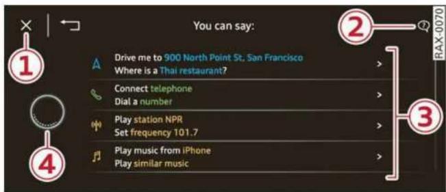
Fig. 18 Upper display: voice recognition system
Switching the voice recognition system on or off
Requirement: the ignition and the MMI must be switched on. A system language supported by the voice recognition system must be set. There must be no phone calls in progress and the parking aid must not be active.
▶ To switch the voice recognition system on, briefly press the w button on the multifunction steering wheel, or depending on the context, press w in the upper display.
To switch the voice recognition system off, press and hold the button on the multifunction steering wheel, or say or press Cancel ①.
Using the voice recognition system
In the voice recognition system menu, possible commands or help settings are displayed for the current dialog ③.
▶ Say the desired command after the signal tone.
▶ To receive additional help for the current dialog, say or press Help ②.
To pause voice recognition, say or press Pause ④. To reactivate voice recognition, press ④ again or briefly press the button on the multifunction steering wheel.
Applies to: MMI: Select on the home screen: SETTINGS > General > Speech dialog system > Allow commands during voice output. If the function is switched on, you can simply say a new command during a prompt.
Activating the online recognizer
Applies to: vehicles with online recognizer
You can activate the online recognizer for additional functions and to improve the results of
voice recognition. A supported menu language must be selected. When there is an active Internet connection, the spoken command is evaluated in the vehicle and online.
▶ When you switch on the voice recognition system for the first time, a menu for the online recognizer opens. Or:
Applies to: MMI: Select on the home screen: SETTINGS > General > Speech dialog system > Consent to online speech recognizer.
- Read the licensing agreements and accept them.
Activating Amazon Alexa 1)
Applies to: vehicles with Amazon Alexa Integration
You can activate Amazon Alexa to access special additional functions. A supported menu language must be selected. A reduced number of commands are available during this.
Requirement: you must be logged in to your myAudi account in the vehicle. The online recognizer must be activated.
▶ Applies to: MMI: Select on the home screen: USER > Connect to Amazon Alexa.
▶ Follow the instructions in the display.
▶ After connecting successfully, turn on the voice recognition system as normal page 26, Switching the voice recognition system on or off, say the activation word “Alexa”, and then say the desired command.
! Note
Read the information about Audi connect, and be sure to note the connectivity costs section in General information on page 179.
External voice operation
Applies to: vehicles with external speech dialog system
You can access and control the voice operation on a connected mobile device through your vehicle.
Switching external voice operation on or off
Requirement: the ignition and the MMI must be switched on. A cell phone must be connected to the MMI with the Handsfree profile page 166. The mobile device being connected must have voice control that can be controlled externally. There must be no phone calls in progress and the parking aid must not be active.
▶ To switch on the external voice operation, press and hold the ⏻ button longer on the multifunction steering wheel.
▶ To switch off the external voice operation, press and hold the ⏻ button longer on the multifunction steering wheel or press Cancel.
Using external voice operation
▶ Say the desired command after the signal tone.
▶ To reactivate voice recognition when it is paused, press the ⏻ button briefly on the multifunction steering wheel or press Resume.
i Tips
AUDI AG simply provides access to control your mobile device with voice operation and does not assume any responsibility for the content and commands within the external voice control.
Global functions
Additional function buttons

Fig. 19 Right side of the multifunction steering wheel
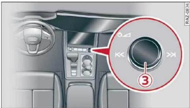
Fig. 20 MMI On/Off knob with joystick function
Adjusting the volume
You can adjust the volume of an audio source or a system message (for example, from the voice recognition system) when the sound is playing.
▶ To increase or decrease the volume, turn the right thumbwheel ③ ⇒ fig. 19 upward or downward, or turn the On/Off knob ③ ⇒ fig. 20 to the right or left.
▶ To mute, push the right thumbwheel or the On/Off knob.
Selecting the previous/next track or station
▶ Press the ◀◀/▶▶| button ④ or briefly press the On/Off knob to the left or right.
Fast forward/rewind
▶ Press and hold the |◀◀ / ▷▶| button ④, or press the On/Off knob to the left or right until the desired playback position is reached.
Quick access steering wheel button
Depending on vehicle equipment, the button ⑤ may provide quick access to various functions.
▶ Applies to: RS models: RS MODE button, see → page 108.
You can program the * button with various functions.
▶ To bring up the function that is currently set, press the * button.
▶ To perform the function that is currently set, press and hold the ✱ button, or:
Applies to MMI: Select on the home screen: VEHICLE > Settings & Service > Steering wheel button assignment.
▶ Select and confirm the desired function.
Switching the voice recognition system on or off
button ②, see ⇒ page 26.
Using the telephone functions
button ①, see ⇒ page 170.

WARNING
Adjust the volume of the audio system so that signals from outside the vehicle, such as police and fire sirens, can be heard easily at all times.
Personalization
User
Personal profiles
Applies to: vehicles with personal profiles
You can store your customized settings in a personal profile. Specific settings are stored automatically in the personal profile that is currently active.
Depending on the equipment, the profile being used is assigned to the vehicle key currently in use. The profile that was last active with the key is loaded when the vehicle is unlocked.
Applies to: MMI: Press USER on the home screen.
Use various profiles to link them to specific vehicle settings.
- Create your customized profile. This is helpful in some situations, for example if multiple people share the vehicle and each person would like to use his or her individual vehicle settings.
– Guest: the guest profile can be used to adjust settings in the vehicle without changing the other profiles.
Active profile
- Rename: you can rename your profile so that you can recognize by name which settings are stored.
- Copy: you can copy your profile. Select the location where the profile will be copied or which profile should be overwritten. The settings will be applied.
- Reset: you can reset your active profile to the factory default settings.
- Reload*: Requirement: the vehicle must be stationary and the ignition must be switched on. You can reload your profile, for example if the seat, mirror, and steering wheel settings could not be applied when changing profiles.
Profile selection
If you would like to change the profile, select another profile from the list.
Switching personal profiles off
- Applies to: MMI: Select on the home screen: USER > ⚙ > Personal profiles.
The personal profiles are switched on at the factory. If you do not wish to use the personal profiles, you can switch the function off.
i Tips
- Certain Infotainment and vehicle settings (such as mirrors) may be stored, depending on vehicle equipment. You can find additional information in the MMI. Select on the home screen: SETTINGS > General > Legal notes > About Audi connect.
– The guest profile cannot be renamed.
- When changing profiles, the new profile settings are loaded in the vehicle.
- You can reset all personal profiles to the factory default settings.
myAudi
Applies to: vehicles with myAudi login
Requirement: you must have successfully registered at my.audi.com.
Logging in from the vehicle
Applies to: MMI
▶ Select on the home screen: USER > myAudi login.
- Log in to myAudi in the vehicle using your e-mail address and password.
To transfer existing destinations from the MMI to your myAudi account one time, confirm the system prompts with Yes.
Automatic login
You can select if and when an automatic login to myAudi in the vehicle should occur.
- Personal profile: Requirement: the personal profile must be turned on and you must not be logged in with the guest profile. Log in to myAudi in the vehicle. Follow the system instructions and save your desired personal profile. You will then always be logged in automatically when your personal profile is active.
- Bluetooth device 1/Bluetooth device 2*: Requirement: after a Bluetooth device has been paired with the MMI, you must be logged in to myAudi in the vehicle. Follow the system instructions and save the desired Bluetooth device. You will be automatically logged in when your Bluetooth device is connected to the MMI, and automatically logged out when the Bluetooth connection to your mobile device is disconnected.
i
Tips
- For some Audi connect Infotainment services, you may also have to enter your my Audi access information when accessing services in the MMI.
- Regardless of the key user and additional users, you can only connect one myAudi account to your vehicle.
User management
Applies to: vehicles with user management
The vehicle owner must be set up as the key user for some Audi connect vehicle control services, which depend on the vehicle equipment.
Setting the key user
Requirement: a key user must not be set yet.
▶ To set a key user for the vehicle, you will need a myAudi account. Register at my.audi.com.
▶ Add your vehicle at my.audi.com and then verify your myAudi account using the verification process that is provided.
▶ Applies to MMI: Select on the home screen: USER > User management > (Key user) > Set key user.
Applies to: MMI: Follow the system instructions and enter the 10-digit vehicle code page 35. The key user is set. You have the rights to use the Audi connect vehicle control services page 181 that depend on vehicle equipment as well as the ability to manage other vehicle functions and any other users.
Managing additional users
Depending on the vehicle equipment, you can grant authorization for additional users to use
Audi connect vehicle control services at my.audi.com.
Removing the key user
If you remove the key user, all other users and their authorizations will be deleted. It will no longer be possible to use the Audi connect vehicle control services, depending on the vehicle equipment.
Requirement: a key user must be set.
▶ Applies to MMI: Select on the home screen: USER > User management > (Key user) > Remove key user.
i
Tips
- Depending on the country, you may be able to use the myAudi app or my.audi.com.
- Depending on the vehicle equipment, you may be able to reset specific functions to the factory default settings.
- Depending on the vehicle equipment, logging into myAudi in the vehicle may not be required to use Audi connect vehicle control services.
- If you sell your vehicle, remove the key user and reset all settings to the factory settings.
- Store the vehicle code in a secure place. It may be necessary to re-enter the vehicle code.
- Pay attention to upper- and lower-case letters when entering the vehicle code.
- If you do not have the 10-digit vehicle code, contact an authorized Audi dealer or authorized Audi Service Facility.
Opening and closing
Central locking
General information

WARNING
- If you leave the vehicle, switch the ignition off and take the key with you. This applies particularly when children remain in the vehicle. Otherwise, children could start the vehicle or operate electrical equipment (such as power windows), which increases the risk of an accident.
- Applies to: vehicles with anti-theft alarm system: When the vehicle is locked from the outside, no one - especially children - should remain in the vehicle, because the windows can no longer be opened from the inside page 34, Anti-theft alarm system. Locked doors make it more difficult for emergency workers to enter the vehicle, which puts lives at risk.
Description
All doors and the luggage compartment lid can be centrally unlocked and locked at once. You can select in the MMI if the entire vehicle or only the driver's door should unlock when unlocking the vehicle page 32. The turn signals flash twice when you unlock the vehicle and flash once when you lock the vehicle. If they do not flash when locking, check if all doors and lids are closed.
Depending on the vehicle equipment, you may have different options for centrally unlocking and locking your vehicle.
- Vehicle key page 36
– Sensors in the door handles page 36 - Lock cylinder on the driver's door page 34
– Central locking switch inside page 33
Vehicle key
The term “vehicle key” refers to the remote control key or convenience key*. The convenience key* is a remote control key with special functions page 36 and page 92.
Power closing\*
When closing a door or the luggage compartment lid, you only have to let it fall lightly into the latch. It then closes automatically .
Automatic locking
If you unlock the vehicle but then do not open any of the doors, the luggage compartment, or the hood within a short period time, the vehicle locks again automatically. This feature prevents the vehicle from being accidentally left unlocked for a long period of time.
Automatic locking (Auto Lock)
The Auto Lock function locks all doors and the luggage compartment lid once the speed has exceeded approximately 9 mph (15 km/h). The vehicle will unlock again if the unlock function in the central locking switch is pressed, the "P" gear is engaged, or the ignition is switched off.
You can open the doors individually from the inside by pulling the door handle one time. To open the rear doors individually, you must pull the door handle twice.
In the event of a crash with airbag deployment, the doors will also automatically unlock to allow access to the vehicle.
Unintentionally locking yourself out
Only lock your vehicle when all of the doors and the luggage compartment lid are closed and there is no key in the vehicle. This reduces the risk of locking yourself out accidentally.
The following features help to reduce the risk of locking your vehicle key in the vehicle:
- If the driver's door is open, the vehicle cannot be locked by pressing the 🔒 button on the remote control key or by touching the locking sensor* on a door.
- If the vehicle key that was used most recently is inside the luggage compartment, the luggage compartment lid will automatically open again after it closes !.
- If the vehicle key that was last used is detected inside the vehicle, then the vehicle cannot be locked from the outside !.

WARNING
Follow the safety precautions page 31.

WARNING
Applies to: vehicles with power closing
- To reduce the risk of injury, make sure that the area where the door is closing is clear during the closing process.
- The closing process can be stopped at any time by pulling on the outer or inner door handle.

Note
The following applies when locking the vehicle:
- If the vehicle key that was last used is detected inside the passenger compartment, then the vehicle cannot be locked from the outside using the sensor. Take the vehicle key with you and lock the vehicle again. Otherwise, the vehicle will not be protected against unauthorized access.
- If you try to lock the vehicle using the button on the vehicle key while the front passenger's or rear door is open, and you accidentally place the vehicle key inside the passenger compartment and close the door, the vehicle will lock at first. But if the key-less system detects a vehicle key inside the vehicle after it locks, then the vehicle will unlock again. The turn signals will flash several times to indicate this. If you do not open the vehicle to remove the vehicle key within a brief period, then the vehicle will lock automatically. This prevents the vehicle from being left unlocked for long periods of time. The vehicle key will then be locked inside the vehicle.
- If the luggage compartment lid closes and the system detects that the last vehicle key that was used is inside the luggage compartment, then the luggage compartment lid will open again. The turn signals will flash several times to indicate this. The doors will lock. Always take the vehicle key with you, or unauthorized persons may be able to enter the vehicle.

Tips
- Do not leave valuables unattended in the vehicle. A locked vehicle is not a safe!
- The LED in the driver's door rail blinks when you lock the vehicle. If the LED turns on for approximately 30 seconds after locking, there is a malfunction in the central locking system. Have the problem corrected by an authorized Audi dealer or authorized Audi Service Facility.
Setting the central locking system
You can adjust the central locking system to your preferences. The settings depend on the vehicle equipment.
Applies to: MMI: Select on the home screen: VEHICLE > Settings & Service > Central locking.
Door unlocking
- If you select All, all doors and the luggage compartment lid will be unlocked when unlocking the vehicle.
- If you select Driver's door, only the driver's door will be unlocked. To unlock all doors and the luggage compartment lid, press the 📋 button on the vehicle key twice. In vehicles with a convenience key*, only the driver's door will unlock when you pull the driver's door handle. If you pull another door handle, the entire vehicle will be unlocked.
The entire vehicle will always be locked when you press the 🔒 button.
Long press to open windows
You can select if all windows and the panoramic glass roof* should open using the vehicle key page 42, Convenience opening and closing. If you press and hold the 📋 button on the vehicle key, all of the windows and the panoramic glass roof* will close.
Disable rear lid handle
You can select if the luggage compartment lid can open with the handle. If you activate this function, the luggage compartment lid can only
be opened with the 2x button on the vehicle key or in the driver's door. In vehicles with a convenience key*, you can still open the luggage compartment lid using the handle if an authorized convenience key is detected page 37.
Fold mirrors
You can select if the exterior mirrors automatically fold in when locking.
Tone when locking 1)
You can select if an audio signal sounds when locking the vehicle.
Open with convenience key
Applies to: vehicles with convenience key
You can deactivate the feature for unlocking using the sensor. The function for locking via the sensor will still be enabled page 36.

Tips
The settings are automatically stored and assigned to the active personal profile.
Central locking switch
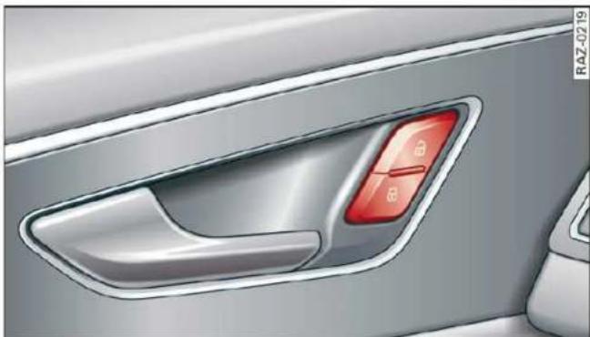
natural_image
Close-up of a car's side panel showing the front and rear camera lens (no text or symbols visible)Fig. 21 Driver's door: central locking switch
▶ To lock or unlock the vehicle, press the 🔒 or 🔒 button ⇒ ⚠️.
When locking the vehicle with the central locking switch, the following applies:
- The doors and the luggage compartment lid cannot be opened from the outside for security reasons, for example, to reduce the risk of unauthorized entry while stopped at a light.
– The LED in the central locking switch turns on when all doors are closed and locked.
- You can open the doors individually from the inside by pulling the door handle one time. To open the rear doors individually, you must pull the door handle twice.
- In the event of a crash with airbag deployment, the doors unlock automatically to allow access to the vehicle.

WARNING
– Follow the safety precautions ⇒ page 31.
- The central locking button works when the ignition is switched off.
– The central locking switch is inoperative when the vehicle is locked from the outside.
Messages

Driver's door: malfunction! Shift to P before ving vehicle. See owner's manual
There is a malfunction in the driver's door. Secure the vehicle before exiting by selecting the "P" selector lever position. Drive immediately to an authorized Audi dealer or authorized Audi Service Facility to have the malfunction repaired.

Central locking: malfunction! See owner's nual
There is a central locking malfunction. If the doors cannot lock, you can emergency lock the doors page 34. Drive to an authorized Audi dealer or authorized Audi Service Facility immediately to have the malfunction corrected.

Door lock: opening while driving is only pos- le with the emergency release. See owner's nual
It is not possible to power unlock the doors at speeds above approximately 9 mph (15 km/h). If you must open doors at higher speeds in cases of emergency, you can manually unlock the door by forcefully pulling the door handle beyond its noticeable resistance two times. Then press the door handle back into its original position, if necessary.
Mechanically unlocking and locking the doors
If the central locking fails, you must unlock or lock the doors separately.

Fig. 22 Driver's door: door lock cylinder

natural_image
Close-up of a car door with a red button and a magnified inset showing a red 3D object (no text or symbols visible)Fig. 23 Door: mechanically locking
Unlocking or locking the driver's door with the mechanical key
▶ Remove the mechanical key page 35.
▶ Insert the mechanical key into the slot under the door handle and pry the cap off fig. 22.
To unlock the driver's door, turn the key to the open position in the direction of arrow ①.
▶ Pull firmly on the door handle to open the driver's door. The door handle swings out slightly farther than normal.
To lock the driver's door, select the "P" position and turn the key once to the close position ②⇒⚠️.
Locking the front passenger's door and rear doors using the mechanical key
The mechanical lock is located on the edge of the doors. It is only visible when the door is open.
▶ Remove the mechanical key page 35.
▶ Remove the cap from the opening fig. 23.
▶ Insert the mechanical key into the slot on the inside and turn it all the way to the left (when locking the right door), or to the right (when locking the left door).
▶ Install the cap in the opening and close the door.
Once the doors are closed, it is no longer possible to open them from the outside. The front doors can be opened from the inside by pulling the door handle one time. The rear doors can be unlocked from the inside by pulling the door handle one time and then opened by pulling the door handle again. If the vehicle is without power, the doors can be unlocked from the inside by first pulling the door handle beyond its noticeable resistance. The doors can then can be opened by pulling the handle again. If the child safety lock in one of the rear doors is activated, you must first pull the door handle from the inside. Then you can open the door from the outside.

WARNING
Follow the safety precautions page 31.
Anti-theft alarm system
Applies to: vehicles with anti-theft alarm system
If the anti-theft alarm system detects a vehicle break-in, audio and visual warning signals are triggered. The anti-theft alarm system is switched on or off when locking or unlocking your vehicle. If the alarm is triggered, it will shut off automatically after a certain amount of time.
Switching the alarm off manually
▶ To switch the alarm off, press the 🔒 button on the vehicle key or switch the ignition on.
Depending on the vehicle equipment, the anti-theft alarm system may have the following features:
Break-in security feature
The alarm will sound if there is a break-in at the doors, hood, and/or luggage compartment lid.
Interior/towing protection monitor
The alarm will be triggered if there are movements detected in the vehicle interior (for example, by animals) or if there is a change in the vehicle angle (for example, when the vehicle is being towed).
You can prevent the alarm from being triggered by deactivating the interior/towing protection monitor.
Deactivating the interior/towing protection monitor
There are the following options for deactivating the interior/towing protection monitor:
▶ Press the 🔒 button on the vehicle key a second time within two seconds. Or
Applies to: vehicles with convenience key: Touch the sensor on the door handle a second time within two seconds. Or
▶ Turn the mechanical key in the door lock to the close position a second time within 2 seconds.
If you lock the vehicle, then the interior/towing protection monitor will stay off until the next time the vehicle is unlocked.

WARNING
No one, especially children, should stay in the vehicle when it is locked from the outside, because the windows can no longer be opened from the inside. Locked doors make it more difficult for emergency workers to enter the vehicle, which puts lives at risk.

Tips
The interior/towing protection monitor only functions correctly when the windows and the panorama glass roof* are closed.
Keys
Key set

Fig. 24 Your vehicle key set
① Vehicle key
You can unlock and lock your vehicle with the vehicle key.
② Mechanical key and release button for mechanical key
A mechanical key is integrated in the vehicle key. To remove it, press the release button and remove the mechanical key.
Using the mechanical key, you can:
– Lock or unlock the glove compartment.
- Manually unlock and lock the doors page 34.
- Unlock the luggage compartment lid using the emergency release page 40.
③ Key fob with vehicle code
Applies to: vehicles with Audi connect vehicle control
Open the key tag and scratch to reveal the vehicle code. You can unlock the Audi connect vehicle control services* for your vehicle with this vehicle code. For additional information, see
⇒ page 181. If a key fob is lost, contact an authorized Audi dealer or authorized Audi Service Facility.
④ PANIC button
In an emergency, you can press the PANIC button to trigger the alarm for the anti-theft alarm system. The vehicle horn and emergency flashers will turn on if you trigger the alarm.
- To trigger the alarm, press the PANIC button ④ ⇒ fig. 24.
- To turn the alarm off, press the red [PANIC] button again.
Lost key/replacing a key
If a vehicle key is lost, contact an authorized Audi dealer or authorized Audi Service Facility. Have this vehicle key deactivated. It is important to bring all keys with you.
If a key is lost, you should report it to your insurance company.
Electronic immobilizer
The immobilizer prevents unauthorized use of the vehicle.
In some cases, it may not be possible to start the vehicle if there is a vehicle key from a different vehicle manufacturer on the key chain.
Data in the vehicle key
When driving, service and maintenance-relevant data is continuously stored in your vehicle key. An authorized Audi dealer or authorized Audi Service Facility can read out this data and tell you about the work your vehicle needs.

WARNING
Follow the safety precautions page 31.

Note
Protect the key against high temperatures and direct sunlight.

For the sake of the environment
Do not dispose of vehicle keys in household trash. They contain materials that can be recycled. Contact an authorized Audi dealer or authorized Audi Service Facility for more information.

Tips
- The vehicle key function can be temporarily disrupted by interference from transmitters near the vehicle working in the same frequency range (such as a mobile device or radio equipment). Always check if your vehicle is locked.
- Applies to: MMI: You can view the number of keys programmed to the vehicle by selecting on the home screen: VEHICLE > Settings & Service > Vehicle information. - For an explanation on conformity with the FCC regulations in the United States and the Industry Canada regulations, see ⇒ page 300.
Unlocking and locking the vehicle
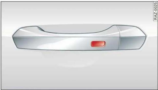
natural_image
3D rendering of a sleek, silver-colored object with a red button and label 'RAZ-0025' on the right (no other text or symbols)Fig. 25 Door handle: sensor for locking
You can unlock and lock your vehicle using either the buttons on the vehicle key or using the sensors* in the door handles. The settings in the MMI specify which doors will unlock page 32.
Unlocking or locking using the vehicle key buttons
▶ To unlock the vehicle, press the 🔑 button
⇒ page 35, fig. 24.
▶ To lock the vehicle, press the 🔒 button once.
Unlocking or locking using the sensors
Applies to: vehicles with convenience key
▶ To unlock a door or the luggage compartment lid, grasp the door handle or luggage compartment lid handle.
▶ To lock the vehicle, close the doors and touch the outer sensor on the door handle once
⇒ fig. 25. Do not grasp the door handle while locking the vehicle, or else the vehicle will not lock. The door cannot be opened for a brief period directly after locking it. This way you have the opportunity to check if the doors locked correctly.

WARNING
Follow the safety precautions page 31.

Tips
- Only use the vehicle key when you can see the vehicle.
- The vehicle can only be locked when the "P" selector lever position is engaged.
- Do not use the vehicle key to lock and unlock when you are inside the vehicle. Otherwise, you could trigger the anti-theft alarm*. If this happens, press the ☐ unlock button.

Tips
Applies to: vehicles with convenience key
- When unlocking or locking the vehicle, the convenience key cannot be more than approximately 4 feet (1.5 m) away from the door handle or luggage compartment.
- Unlocking with the convenience key (keyless access) can be deactivated in the MMI system page 32.
- To prevent the vehicle battery from discharging, the energy management gradually switches off convenience functions that are not needed. You then may no longer be able to unlock your vehicle with the sensors.
LED and battery in the vehicle key

Fig. 26 Vehicle key: removing the battery holder
LED in the vehicle key
The LED ① indicates the vehicle key function.
▶ If you press a button briefly, the LED blinks once.
▶ If you press and hold a button (convenience opening/closing), the LED blinks several times.
▶ If the LED does not blink, the vehicle key battery is drained. Replace the battery in the vehicle key.
Replacing the vehicle key battery
▶ Remove the mechanical key page 35 and insert it at an angle into the opening fig. 26.
▶ Push the mechanical key in the opening in the direction of the arrow to operate the release button on the inside ②. To reduce the risk of damage, do not try to pry off the cover.
▶ Remove the cover from the battery tray.
- Insert the new battery with the “+” symbol facing up.
▶ Close the battery tray with the cover.
▶ Insert the mechanical key.

For the sake of the environment
Discharged batteries must be disposed of using methods that will not harm the environment. Do not dispose of them in household trash.

Tips
Replacement batteries for the vehicle key must meet the same specifications as the original battery.
Luggage compartment lid
General information

WARNING
- Applies to: vehicles with anti-theft alarm system: When the vehicle is locked from the outside, no one - especially children - should remain in the vehicle, because the windows can no longer be opened from the inside
→ page 34. Locked doors make it more difficult for emergency workers to enter the vehicle, which puts lives at risk. - Always close and lock the luggage compartment lid and the doors when the vehicle is not in use. Otherwise someone such as a
child could enter the vehicle through the luggage compartment and become locked inside it. To reduce the risk of injury, do not allow children to play in or around the vehicle.
- To reduce the risk of injuries by pinching, make sure that no one is in the operating area of the luggage compartment lid, including the hinge areas and the upper and lower edge of the luggage compartment lid.
- After closing the luggage compartment lid, make sure that it is latched. The luggage compartment lid could open suddenly while driving, which would increase the risk of an accident.
- Never drive with the luggage compartment lid ajar or open, because poisonous gases from the surrounding area can enter the vehicle interior and increase the risk of asphyxiation.
- If there is a luggage rack (such as a bicycle rack) on the luggage compartment lid, the luggage compartment lid may not open completely under certain circumstances or it could close by itself if open due to the extra weight. Therefore, the open luggage compartment lid must be given additional support or the cargo must first be removed from the luggage rack.
- Applies to: vehicles with power-operated or sensor-controlled luggage compartment lid: Pay careful attention when closing the luggage compartment lid. Otherwise, you could cause serious injury to yourself or others despite the pinch protection.

Note
The luggage compartment lid can bump into objects such as the garage ceiling when opening and become damaged.

Tips
- When the vehicle is locked, the luggage compartment lid can be unlocked separately by pressing the 2x button on the vehicle key twice. The luggage compartment lid locks automatically when it is closed again.
- The ability to open the luggage compartment lid using the handle can be deactivated or activated in the MMI page 32.
Opening and closing the luggage compartment lid

natural_image
Interior view of a car seatbelt buckle with red buttons (no text or symbols visible)Fig. 27 Driver's door: opening the luggage compartment lid
Opening the luggage compartment lid
▶ When the ignition is switched off, press the 📊 button on the vehicle key twice. Or
▶ Select the "P" selector lever position and pull the ≈ switch in the driver's door. Or
Applies to: vehicles without convenience key: Unlock the vehicle or the luggage compartment lid using the button 📋 / 🌐 on the vehicle key and press the handle in the luggage compartment lid. Or
Applies to: vehicles with convenience key: Press the handle in the luggage compartment lid. The vehicle key cannot be more than approximately 4 feet (1.5 m) away from the luggage compartment.
Closing the luggage compartment lid
▶ See page 39, Automatic luggage compartment lid.

WARNING
Follow the safety precautions page 37.
Automatic luggage compartment lid
Applies to: vehicles with automatic luggage compartment lid

Fig. 28 Luggage compartment lid: ① closing button*, ② lock button* (vehicles with convenience key*)
The luggage compartment lid can be opened and closed automatically in General information on page 37.
Opening the luggage compartment lid
▶ When the ignition is switched off, press and hold the 2× button on the vehicle key twice page 35, fig. 24. Or
▶ Select the "P" selector lever position and pull the ≈ switch* in the driver's door. Or
Applies to: vehicles with convenience key: Press the handle in the luggage compartment lid. The vehicle key cannot be more than approximately 4 feet (1.5 m) away from the luggage compartment.
Closing the luggage compartment lid
-
Press the ≈ button in the luggage compartment lid. Or
▶ Press the handle in the luggage compartment lid. Or
▶ Press the luggage compartment lid downward slightly. Or
▶ When the ignition is switched on, pull the → switch in the driver's door → page 38, fig. 27 until the luggage compartment lid is closed. Or
Applies to: vehicles with convenience key: Press and hold the 2x button on the vehicle key while the ignition is switched off until the luggage compartment lid closes. Make sure there is enough distance (maximum of approximately 9 feet (3 m)) between you and the luggage compartment lid. Or -
Press the ⏻ button in the luggage compartment lid. Or
Applies to: vehicles with convenience key: While the ignition is switched off, press the ☐* button in the luggage compartment lid. The vehicle key must not be more than approximately 4 feet (1.5 m) away from the luggage compartment and it must not be inside the vehicle. If you press the ☐* button, then the vehicle will lock.
Storing the luggage compartment lid opening position
The position must be at a certain height or higher to store.
▶ Bring the luggage compartment lid into the desired open position. If you want to move the luggage compartment lid to a lower position, move it slowly in small increments; otherwise, the luggage compartment lid will close automatically.
▶ Press and hold the ≈ button in the luggage compartment lid for at least four seconds to store the new open position. A visual and audio signal will follow.
▶ To set a higher open position, wait at least five seconds and then carefully press the luggage compartment lid upward.
▶ Press and hold the ≈ button again for at least four seconds to store the new open position.
The automatic opening or closing will stop if:
- You press the ⬇ button or press the handle in the luggage compartment lid again Or
- If something blocks the luggage compartment lid or makes it difficult for the lid to move.
If you press the 🔗 button or press the handle in the luggage compartment lid again, the luggage compartment lid will open again.

WARNING
Follow the safety precautions page 37.

Tips
The luggage compartment lid can be operated manually if the vehicle battery is low. It is necessary to use more force when doing this.
Move the lid slowly to reduce the amount of force needed.
Opening and closing the luggage compartment lid with foot motion (kicking movement)
Applies to: vehicles with sensor-controlled luggage compartment lid

natural_image
Illustration of a person standing near a car with a red arrow pointing downward (no text or symbols)Fig. 29 Vehicle rear: foot motion (example)
The luggage compartment lid can be opened and closed automatically in General information on page 37.
Requirements: you must be carrying your convenience key* with you. The ignition must be switched off. You must be standard behind the luggage compartment lid, toward the left side of the vehicle. Depending on the equipment, it may also be possible to stand near the center of the vehicle or toward the right side of it.
▶ Move your foot back and forth under the bumper one time fig. 29. Do not touch the bumper. Make sure you have firm footing. The luggage compartment lid will open or close once the system detects the movement. The automatic opening or closing will be canceled if you repeat one of the movements described.

WARNING
Follow the safety precautions page 37.

Tips
The luggage compartment lid will only open or close if you perform the movement as described. This prevents the luggage compartment lid from opening or closing due to similar movements, such as when you walk between the rear of the vehicle and your garage
door. In some situations, the function may be limited or temporarily unavailable. This may happen if:
- You are standing too close to the bumper or too far away from it
– The luggage compartment lid was closed or opened immediately beforehand - You park close to a hedge and the branches move back and forth under the vehicle for a long period of time
- You clean your vehicle, for example with a pressure washer or in a car wash
- There is heavy rain
- The bumper is very dirty, for example after driving on salt-covered roads
– There is interference to the vehicle key's radio signal, such as from mobile devices or remote controls
Mechanically unlocking the luggage compartment lid
The luggage compartment lid can be released from the inside in an emergency.

Fig. 30 Inner luggage compartment lid: access to the emergency release
▶ Fold the backrest on the rear bench seat forward page 81.
▶ Remove the mechanical key page 35.
▶ Using the mechanical key, pry the cover ➕ off the luggage compartment lid trim panel.
▶ Press the lever with the mechanical key in the direction of the arrow to release the luggage compartment lid.

WARNING
Follow the safety precautions page 37.

WARNING
If you have folded the backrests into the upright position, always check if the lock is correctly engaged by pulling forward on the backrest.
Child safety lock
The child safety lock prevents the rear doors from being opened from the inside and the rear power windows from being operated.

natural_image
Interior view of a double-chamber refrigerator with gray compartments and red buttons (no text or symbols visible)Fig. 31 Driver's door: controls
▶ To activate or deactivate the child safety lock (rear power windows and interior door handle) for the rear doors, press the left and/or right button in the driver's door ⇒ fig. 31. The indicator light in the button turns on/blinks.
▶ Make sure the child safety lock is working by checking the function on the rear power window switch and door handle.
Applies to: vehicles with controls for the climate control system in the rear and MMI: To also restrict the operation of the climate control system in the rear, select on the home screen: SETTINGS > Display & brightness > Operation in rear.
When the child safety lock is switched on, the following functions are disabled:
– The rear inner door handles
– The rear power windows
- The control panel* for the climate control system in the rear
- The buttons in the rear for the sunshades*
Message in the instrument cluster display
/ Child safety lock: malfunction! Please contact Service
There is a malfunction in the child safety lock. Press the 🔊 button again.
If the message stays on, drive immediately to an authorized Audi dealer or authorized Audi Service Facility to have the malfunction repaired.

WARNING
– Follow the safety precautions page 31.
- A malfunction in the child safety lock could allow the rear doors to be opened from the inside, which increases the risk of an accident.
Power windows
Opening and closing windows and sunshades

Fig. 32 Driver's door: power window switch
Power window switches:
① Left front door
② Right front door
③ Left rear door
④ Right rear door
Opening and closing the windows
The driver can control all power windows. All power window switches are equipped with a two-stage function:
▶ To open or close the window completely, press the switch down or pull the switch up briefly to the second level. The operation will stop if the switch is pressed or pulled again.
▶ To select a position in between opened and closed, press or pull the switch to the first level until the desired window position is reached.
Opening and closing sunshades on the rear side windows
Applies to: vehicles with power sunshades on the rear side windows
Requirement: the window whose sunshade you will operate must be closed.
▶ To close or open the sunshade from the driver's seat, pull or press the ➕ power window switch for that window in the driver's door.
▶ To close or open the sunshade from the rear, pull or press the 📄 power window switch for that window in the rear door. Or:
Correcting a malfunction in the one-touch up/down function
You can reactivate the one-touch up/down function if it malfunctions.
▶ Pull the power window switch up until the window is completely raised.
▶ Release the switch and pull it up again for at least one second.

WARNING
– Follow the safety precautions page 31.
- Never close the windows or sunshades* carelessly or in an uncontrolled manner, because this increases the risk of injury.

Tips
- The windows will automatically open slightly when you open the doors.
- If the window in the driver's or front passenger's door is completely open, it will raise slightly when the door is opened. The window will lower again when you close the door.
- You can still open and close the windows for several minutes after turning the ignition off. The power windows do not switch off until the driver's door or front passenger's door has been opened.
- The power windows are equipped with pinch protection. The automatic window may stop
closing and will open all the way again even if no obstacle is detected. Pull the power window switch up until the window is completely raised.
Convenience opening and closing
Applies to: vehicles with convenience key
Convenience opening or closing the windows or panoramic glass roof\*
You can set in the MMI if all windows or the roof* should open or close all at once page 32, Setting the central locking system.
▶ Press and hold the 📋 / 📋 button on the vehicle key until all windows and the roof* have reached the desired position ⇒ !.
- Touch the sensor* on the door handle until all of the windows and the roof* are closed. Do not place your hand in the door handle when doing this.
When all of the windows and the roof* are closed, the turn signals will flash once.
Convenience opening and closing the sunshade\*
Applies to: vehicles with power sunshade
You can open or close all of the sunshades at once.
▶ Press and hold the 📁 button in the rear door.

WARNING
- Never close the windows or panoramic glass roof* carelessly or in an uncontrolled manner, because this increases the risk of injury.
- For security reasons, the windows and the panoramic glass roof* can only be opened and closed with the vehicle key at a maximum distance of approximately 6.5 feet (2 m) from the vehicle. Always pay attention when using the 📋 button to close the windows and the panoramic glass roof* so that no one is pinched. The closing process will stop immediately when the 📋 button is released.
Panoramic glass roof
Operating the panoramic glass roof and roof sunshade
Applies to: vehicles with panoramic glass roof and roof sun-shade

Fig. 33 Headliner: panoramic glass roof and sunshade* buttons
The control buttons are equipped with a two-stage function.
When tilting or opening the roof, the roof sun-shade will open partially or completely if the sun-shade is closed.
Operating the roof sunshade
▶ Opening and closing the sunshade: push the switch in the headliner ③ forward or toward the rear to the second level.
▶ Partially opening the sunshade: press the switch to the first level until the sunshade reaches the desired position.
Operating the roof
▶ Tilting the roof: press the 📋 switch in the headliner briefly upward to the second level ①.
- Closing the tilted roof: pull the 📋 switch downward briefly to the second level.
▶ Opening the roof: slide the 📋 switch back briefly twice in a row to the second level ②.
- Closing the roof: push the 📋 switch forward briefly to the second level.
▶ Opening or closing partially: slide the switch to the first level and hold it there until the roof reaches the desired position.
Quick opening
You can also open the roof and roof sunshade in one movement.
▶ Push the 📋 switch back briefly to the second level ② twice in a row.
Roof emergency closing
If an object is detected when closing, the roof will open again automatically. In this case, you can then close it with the power emergency closing function.
▶ Within five seconds after the sunroof opens automatically, pull the applicable button until the roof is closed.

WARNING
To reduce the risk of injury, always pay attention when closing the roof. Always switch the ignition off and take the key with you when leaving the vehicle.

Note
Always close the roof when you leave the vehicle and when there is precipitation to reduce the risk of damage to the interior equipment, particularly the electronic equipment.

Tips
- After switching off the ignition, the roof and sunshades can still be operated for several minutes as long as neither of the front doors are opened.
- It is not possible to open the roof when temperatures are too low.
Garage door opener
Description
Applies to: vehicles with garage door opener
With the garage door opener, you can activate systems such as the garage doors, security systems or house lights from inside your vehicle.
These functions are operated in the MMI. Multiple receivers can be programmed, which can control the functions of up to eight 1) hand-held transmitters.

WARNING
- When operating or programming the garage door opener, make sure that no people or objects are in the area immediately surrounding the equipment. People can be injured or property can be damaged if struck when closing.
- Do not allow yourself to be distracted from traffic by the viewing and operating the displays.

Tips
- If you sell your vehicle, remove the key user page 30 and reset all settings to the factory settings page 227.
- For an explanation on conformity with the FCC regulations in the United States and the Industry Canada regulations, see page 300.

Tips
Before you program your system to the garage door opener, first check the compatibility:
- Ask an authorized Audi dealer or authorized Audi Service Facility or check at www.homelink.com. You can also find more information about HomeLink there.
- You can display information about HomeLink (compatibility level/status/country code/HomeLink generation) in the MMI:
- Select on the home screen: VEHICLE > Settings & Service > Garage door opener > ⓘ.
Operation
Applies to: vehicles with garage door opener
Requirements: the remote control transmitter must be programmed page 44, the vehicle
must be within range of the system, and the ignition must be switched on.
There are multiple options to open or close the system (such as the garage door).
▶ If you have only programmed one remote control transmitter, press the ⏻ button on the lower display. Or
▶ If you have programmed multiple remote control transmitters, press the ⏻ button on the lower display and then press the respective system button. Or
▶ If you have configured the programmable steering wheel button*, press the * button → page 28 and then press the respective button for the system. Or
Applies to: vehicles with location pairing: If you have programmed Location pairing, press the button for this in the upper display (notification center page 21). As you approach the system, the button is displayed on the MMI.
If transmission was successful, the message:
Send to: XXX will appear.
Programming
Applies to: vehicles with garage door opener
You can program both fixed code and rolling code systems in the MMI using the procedure that is described.
Requirement: the ignition must be switched on.
Programming the system
Applies to: MMI
Requirement: the hand transmitter must be present and the vehicle must be within range of the system (such as the garage door) that you would like to program.
▶ If you are programming the garage door opener for the first time, press the button on the lower display. Follow the instructions in the MMI. Or
▶ If you would like to program other systems, select on the home screen: VEHICLE > Settings & Service > Garage door opener. Select the
desired button: +. Follow the instructions in the MMI.
▶ If you would like to reprogram systems that are already programmed, select on the home screen: VEHICLE > Settings & Service > Garage door opener. Press the 🔊 button and select 🔊 for the system to be reprogrammed. Select: Program. Follow the instructions in the MMI.
With some systems, the garage door opener will be immediately available after programming. With other systems, the garage door opener must also be synchronized.
Synchronizing 1)
Requirement: the hand transmitter must already be programmed and the vehicle must be within range of the system (such as the garage door).
If the system synchronization is performed directly after the programming procedure, follow the instructions on the MMI.
If you would like to sync at a later time:
Applies to: MMI: Select on the home screen: VEHICLE > Settings & Service > Garage door opener.
▶ Press the button for the system that you would like to synchronize.
▶ Follow the instructions in the MMI.
GPS pairing
Applies to: vehicles with GPS pairing
For easier operation, you can program your system's location.
Requirements: the respective hand transmitter must be programmed page 44 and the vehicle must be located in front of the system.
Applies to: MMI: Select on the home screen: VEHICLE > Settings & Service > Garage door opener.
▶ Press the 🔊 button.
▶ Press the √ button for the system your vehicle is facing.
▶ Select: Location pairing.
▶ Follow the instructions in the MMI.
Only a maximum of three systems can be displayed in the notification center page 21. If you would like to have all systems displayed, press ☐☐.
Renaming programmed systems
You can rename the programmed systems individually.
▶ Applies to: MMI: Select on the home screen: VEHICLE > Settings & Service > Garage door opener.
▶ Press the 🔊 button.
▶ Press the √ button for the system that you would like to rename.
▶ Select: Rename.
▶ Follow the instructions in the MMI.
Deleting programmed systems
The programmed systems can be deleted individually or all at once.
▶ Applies to: MMI: Select on the home screen: VEHICLE > Settings & Service > Garage door opener.
▶ Press the 🔊 button.
▶ To delete an individual system, press the □ button for the desired system. If the checkmark √ is set, select: Delete.
▶ To delete all systems, select: All > Delete.
i Tips
- Make sure the batteries in the hand transmitter are charged before starting the programming process.
- The programming process may take up to 30 seconds. It may be necessary for the hand transmitter to be pressed again in the meantime.
- The garage door opener may need to be synchronized with the system after programming. Follow the manufacturer's instructions for doing this.
i Tips
In some cases, the system may need to be programmed in a different mode ("D mode").
– Switch the ignition on.
- Applies to: MMI: Select on the home screen: VEHICLE > Settings & Service > Garage door opener.
- Press and hold the desired button ⊕.
- Select Yes, in D mode and follow the instructions on the MMI.
Lights and Vision
Exterior lighting
Switching lights on and off

Fig. 34 Instrument panel: light button module
① Light sensor
Press and hold ① until the desired light function is selected. The selected function is displayed briefly in the instrument cluster. When switching on the ignition, the AUTO light function is automatically selected.
- AUTO - The automatic headlights adapt to the surrounding brightness automatically. The daytime running lights* will automatically turn on. In vehicles for certain markets, you can switch the automatic daytime running lights* on and off in the MMI.
- ID - Low beam headlights. As soon as the ignition is switched on, you can switch on the low beam headlights manually.
- 300 - Parking lights. You can switch on the parking lights at speeds under 20 mph (32 km/h).
- USA models: OFF - You can switch off all light functions at speeds under 6 mph (10 km/h).
- Canada models: OFF - You can only switch off all light functions when the vehicle is parked and the ignition is switched off.
When the low beam headlights or parking lights are switched on, the respective 📋 or 🐥 indicate light appears in the instrument cluster.
② All-weather lights FRONT
The headlights automatically adjust so that there will be less glare, for example when the road surface is wet.
Automatic headlight range control
Your vehicle is equipped with automatic head-light range control. It reduces glare for oncoming traffic if the vehicle load changes. The headlight range adjusts automatically.
Audi adaptive light
Applies to: vehicles with adaptive light
Audi adaptive light provides better visibility when driving in the dark. The lights are adapted to the road conditions based on speed, such as when driving on expressways, rural roads, at intersections, and around curves. The adaptive light only functions when the automatic headlights are activated.
! WARNING
- Follow the safety precautions and note the limits of the assist systems, sensors, and cameras page 119.
- Automatic headlights are only intended to assist the driver. They do not relieve the driver of responsibility to check the headlights and to turn them on manually based on the current light and visibility conditions. For example, fog cannot be detected by the light sensors. So always switch on the low beams 📋 under these weather conditions and when driving in the dark.
i Tips
- If the vehicle battery has been discharging for a while, the parking light may switch off automatically. Avoid using the parking lights for several hours.
– Follow the regulations applicable to the country where you are operating the vehicle when stopping the vehicle and when using the lighting systems. - A warning tone will sound if you open the door when the exterior lights are switched on.
- Only the front headlights turn on when the daytime running lights are switched on*. In vehicles in certain markets, the tail lights will also turn on.
- In cool or damp weather, the inside of the headlights, turn signals, and tail lights can
fog over due to the temperature difference between the inside and outside. They will clear shortly after switching them on. This does not affect the service life of the lighting. - When the parking lights are switched on and the ignition is switched off, the symbol appears in the light switch module.
Turn signal and high beam lever

Fig. 35 Lever: switching on the turn signal and high beams
The lever operates the turn signals, the high beams and the headlight flasher.
Turn signals
The turn signal activates when you move the lever into a turn signal position when the ignition is switched on. The respective ⇔ or ➕ indicator light flashes.
① Right turn signal
② Left turn signal
The turn signal blinks three times if you tap the lever (convenience turn signal).
If an indicator light blinks twice as fast as usual, a turn signal bulb has failed. Carefully drive to an authorized Audi dealer or authorized Audi Service Facility immediately to have the malfunction corrected.
High beams and headlight flasher
▶ Move the lever to the corresponding position:
③ High beams on (vehicles with high beam assistant*) ⇒ page 48
④ High beams off or headlight flasher
The indicator light in the instrument cluster turns on.
! WARNING
High beams can cause glare for other drivers, which increases the risk of an accident. For this reason, only use the high beams or the headlight flasher when they will not create glare for other drivers.
High beam assistant
Applies to: vehicles with high beam assistant
The high beam assistant automatically turns the high beams on or off depending on the surrounding conditions.
A camera on the rearview mirror mount can detect light sources from other road users. The high beams switch on or off automatically depending on the position of vehicles driving ahead and on-coming vehicles, the vehicle speed as well as other environmental factors and traffic conditions.
Switching on the high beam assistant
Requirement: the AUTO light function must be selected and the high beam assistant must be switched on in the MMI page 49.
To activate the high beam assistant, tap the lever forward ③⇒ page 48, fig. 35. The indicator light appears in the instrument cluster display and the high beams are switched on or off automatically. The indicator light turns on if the high beams are switched on.
Switching the high beams on or off manually
If the high beams did not switch on or off automatically as expected, you may switch them on or off manually instead:
▶ To switch the high beams on manually, tap the lever forward ③ → page 48, fig. 35. The indicator light turns on.
▶ To switch the high beams off manually, pull the lever back ④ ⇒ page 48, fig. 35. The high beam assistant is deactivated.
Operating the headlight flasher
To operate the headlight flashers, pull the lever back ④ ⇒ page 48, fig. 35. If the high beam assistant is activated, but the high beams were not turned off, the high beam assistant remains activated.

WARNING
- Follow the safety precautions and note the limits of the assist systems, sensors, and cameras page 119.
– High beam assistant is only intended to assist the driver. The driver is still responsible for controlling the headlights and switching them manually depending on light and visibility conditions.
– High beams can cause glare for other drivers, which increases the risk of an accident. For this reason, only use the high beams or the headlight flasher when they will not create glare for other drivers.

Tips
Certain settings are stored automatically in the active personal profile.
Adjusting the exterior lighting
You can adjust the exterior lighting separately. The settings depend on the vehicle equipment.
Applies to: MMI: Select on the home screen: VEHICLE > Light & Visibility > Exterior lighting.
Automatic headlights
You can adjust the following settings in the Automatic headlights menu:
Activation time - You can adjust if the headlights switch on Early, Medium, or Late based on the sensitivity of the light sensor.
High beam assistant > System - You can switch the high beam assistant on and off.
Entry/exit lighting
When it is dark, the Entry/exit lighting illuminates the area around the vehicle when unlocking the vehicle and after switching off the ignition and opening the driver's door. The entry/exit lighting only works when it is dark and the light switch is in the AUTO light function.
Daytime running lights
USA models: The daytime running lights can be switched on and off.
Canada models: The daytime running lights cannot be switched off. The lights activate automatically each time the ignition is switched on.

Tips
Certain settings are stored automatically in the active personal profile.
Emergency flashers
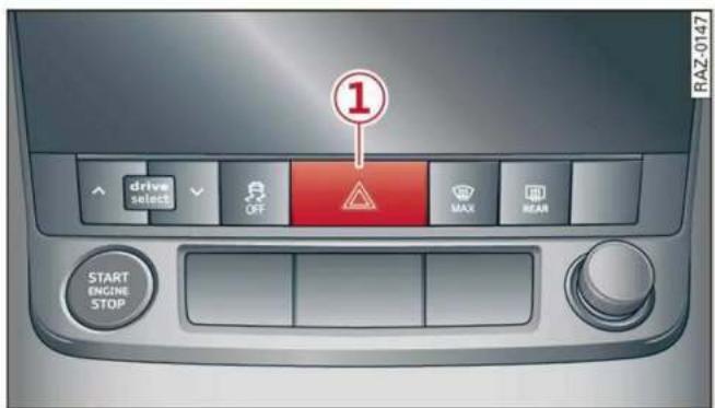
Fig. 36 Center console: emergency flashers
The emergency flashers help to make other drivers aware of your vehicle in dangerous situations.
▶ Press the △ button ① to switch the emergency flashers on or off.
When the emergency flashers are turned on, the ⏻ and ⏱ indicator lights will flash at the same time.
You can indicate a lane change or a turn when the emergency flashers are switched on by using the turn signal lever. The emergency flashers stop temporarily.
The emergency flashers also work when the ignition is turned off.

Tips
You should switch the emergency flashers on if:
– you are the last car in a traffic jam so that all other vehicles approaching from behind can see your vehicle
– your vehicle has broken down or you are having an emergency
- your vehicle is being towed or if you are towing another vehicle
Messages
If the indicator light turns on, a bulb has failed. The displayed message indicates the cause and possible solutions. If one of the messages does not turn off, drive immediately to an authorized Audi dealer or authorized Audi Service Facility to have the malfunction repaired.
Audi adaptive light: malfunction! See owner's manual
Adaptive light* is not working. The headlights still function. Drive immediately to an authorized Audi dealer or authorized Audi Service Facility to have the malfunction repaired.
High beam assistant: malfunction! See owner's manual
You can still switch the high beams on or off manually. Drive immediately to an authorized Audi dealer or authorized Audi Service Facility to have the malfunction repaired.
High beam assistant: currently unavailable. Camera view limited due to surroundings. See owner's manual
This message appears if the camera's visual field is blocked. The system will switch itself off. Try switching the systems on again later.
Automatic headlights: malfunction! See owner's manual
The light/rain sensor is malfunctioning. The low beams remain switched on at all times for safety reasons with the AUTO light function. Drive immediately to an authorized Audi dealer or authorized Audi Service Facility to have the malfunction repaired.
Interior lighting
Front interior lighting

natural_image
Top-down view of a car's front panel showing the internal keyway with red buttons and a numbered indicator (1), no text or symbols present.Fig. 37 Headliner: interior lighting
Interior lighting buttons
※* - Interior lighting on/off
- Door contact switch on/off. The interior lighting is controlled automatically.
Touch-sensitive reading lights
▶ To turn a reading light on or off, touch the surface ① briefly.
▶ To activate the manual dimming function, touch the surface ① when the light is switched off and keep touching it until the desired brightness is reached.
Rear interior lighting
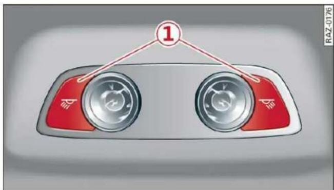
Fig. 38 Headliner: reading lights
Reading lights
▶ To turn a reading light on or off, press the button ①.
▶ To activate the manual dimming function*, touch the button when the light is switched off ① and keep touching it until the desired brightness is reached.
Interior lighting
Applies to: vehicles with interior lighting
The ambient lighting turns on when the ignition is switched on. The ambient lighting is deactivated when the light function is OFF.
You can adjust the interior lighting individually. The settings depend on the vehicle equipment.
Applies to: MMI: Select on the home screen: VEHICLE > Light & Visibility > Interior lighting.
You can choose among predefined color profiles, such as Maritime.
Additional settings and profiles:
- Brightness: you can adjust the brightness for all of the interior lighting.
- Individual: you can adjust the brightness and color of the interior lighting separately, divided into contour and surface lighting.
- Drive select: the contour and surface lighting color changes depending on the selected Audi drive select* mode.
i Tips
- Depending on vehicle equipment, when the Drive select function is activated, the color of the contour and surface lighting may briefly change to red or blue when the interior temperature is manually increased or decreased.
- Certain settings are stored automatically in the active personal profile.
Display brightness
You can adjust the instrument and display illumination separately. The settings depend on the vehicle equipment.
Applies to: MMI: Select on the home screen: SETTINGS > Display & brightness.
Possible settings in the MMI:
- Cockpit dimming
- Head-up display
- MMI
- Virtual cockpit
Vision
Adjusting exterior mirrors

Fig. 39 Driver's door: knob for the exterior mirrors
▶ Turn the knob in the driver's door to the desired position:
0 - All adjustment functions are deactivated.
☐ / ☐ - Selects the left or right exterior mirror. To adjust the mirror glass in a mirror, press the knob in the desired direction.
- Heats* the mirror glass depending on the outside temperature.
- Folds the exterior mirrors*. To fold the mirrors out, turn the knob to one of the other positions. In the MMI, you can select if the mirrors fold in automatically when you lock the vehicle page 32.
Front passenger's exterior mirror tilt function\*
Requirement: the knob must be in the position for the front passenger's exterior mirror.
To help you see the curb when backing into a parking space, the surface of the mirror will tilt slightly when reverse gear is selected.
You can adjust the mirror surface by turning the knob in the desired direction.
The mirror moves from the reversing position back to the original position:
- When you switch the ignition off
- Once you drive forward at speeds faster than 9 mph (15 km/h).
- When the knob is no longer in the position for the front passenger exterior mirror

WARNING
Curved mirror surfaces (for example convex) enlarge the field of vision. However, they make objects in the mirror appear smaller and farther away. When using these mirrors to estimate your distance to vehicles behind you when changing lanes, you could estimate incorrectly, which increases the risk of an accident.

Note
- Applies to: vehicles with power folding exterior mirrors: If the mirror housing was moved by outside forces (such as an impact when maneuvering), you must use the power folding function to fold the mirror all the way out. The mirrors will make a loud noise when they latch into place. The mirror housing must not be moved back into place by hand because this could impair the function of the mirror mechanism.
- Applies to: vehicles without power folding exterior mirrors: If the mirror housing was moved by outside forces (such as an impact when maneuvering), you must move it back in place by hand.
- If you wash the vehicle in an automatic car wash, you must fold the exterior mirrors in to reduce the risk of damage to the mirrors. Never fold power folding exterior mirrors* by hand. Only fold them in and out using the power controls.

Tips
- Certain settings are stored automatically in the active personal profile.
- If the power adjusting function malfunctions, the glass in both mirrors can be adjusted by pressing on the edge of it by hand.
Dimming the mirrors
Manual dimming rearview mirror
▶ Pull the lever on the bottom of the mirror back.
Automatic dimming rearview mirror\*
The interior and exterior mirrors dim automatically when light shines on them, for example from headlights on a vehicle behind you.

WARNING
- If the glass on an automatic dimming mirror* breaks, electrolyte can leak out. This liquid can irritate the skin, eyes and respiratory system. If there is contact with the fluid, flush immediately with plenty of water. Consult a physician if necessary.
- Repeated or long-term exposure to electrolyte fluid can lead to irritation of the airways, especially in people with asthma or other respiratory conditions. Take deep breaths immediately after leaving the vehicle or, if this is not possible, open all of the doors and windows as wide as possible.
- If electrolyte fluid comes into contact with the eyes, flush them thoroughly with plenty of clean water for at least 15 minutes and then seek medical attention.
- If electrolyte fluid comes into contact with the skin, flush the affected area with clean water for at least 15 minutes, and then clean with soap and water and seek medical attention. Clean affected clothing and shoes thoroughly before wearing again.
- If the fluid was swallowed and the person is conscious, flush the mouth with water for at least 15 minutes. Do not induce vomiting unless this is recommended by medical professionals. Seek medical attention immediately.

Note
If the glass on an automatic dimming mirror* breaks, electrolyte can leak out. This liquid damages plastic surfaces and paint. Clean this liquid as quickly as possible, for example with a wet sponge.

Tips
- If the light reaching the rearview mirror is obstructed, the automatic dimming mirror* will not function correctly.
- The automatic dimming mirrors* do not dim when the interior lighting is turned on or reverse gear is selected.
Sun visors

Fig. 40 Roof headliner: sun visor
Sun visor
The sun visors for the driver and front passenger can be released from their mounts and turned toward the doors ①.
They can also be moved back and forth length-wise in this position.
Vanity mirror
The mirror light switches on when the cover over the vanity mirror ② opens.
Sunshade
Applies to: vehicles with sunshade

natural_image
Top-down view of a car's roof structure with a red arrow pointing to a specific component (no text or symbols)Fig. 41 Rear window: sunshade
Rear window sunshade
▶ Pull the sunshade out and attach it to the retainer on the luggage compartment lid.
Windshield wipers
Switching the windshield wipers on

Fig. 42 Lever: windshield wipers

Fig. 43 Lever: rear window wiper
▶ Move the windshield wiper lever ⏻ to the corresponding position:
① Windshield wipers off
① Rain sensor/intermittent mode. The windshield wipers switch on once the vehicle speed exceeds approximately 2 mph (4 km/h) and it is raining. The higher the sensitivity of the rain sensor that is set (switch ⑥ to the right), the earlier the windshield wipers react to moisture on the windshield. You can deactivate the rain sensor mode, which switches the interval mode on. In intermittent mode, you can adjust the interval time using the switch ⑥.
▶ Applies to: MMI: Select on the home screen: VEHICLE > Light & Visibility > Rain sensor.
② Slow wiping
③ Fast wiping
④ Single wipe. If you hold the lever in this position longer, the wipers switch from slow wiping to fast wiping.
⑤ Clean the windshield 🎨. The number of wipes and afterwipes depends on how long the lever is held in position ⑤.
The wipers wipe one time after several seconds of driving to remove water droplets. You can switch this function off by moving the lever to position
⑤ within ten seconds of the afterwipe. The after-wipe function is reactivated the next time you switch the ignition on.
If you hold the lever in position ⑤ for longer than half a second, the edge wiping feature will be activated. This moves the wiper closer to the edge of the windshield and performs an after-wipe to clean the residue that results from the wiping process from the edge of the windshield. The function is available when driving at speeds up to 75 mph (120 km/h).
Clean the headlights*. The headlight washer system* operates only when the low beam headlights are on. If you move the lever to position
⑤, the headlights and the night vision assist camera* are cleaned at intervals.
⑦ Wipe the rear window ☐. The number of wipes depends on the windshield wiper movement.
The rear wiper automatically switches on when the reverse gear is selected and the front wind-shield wipers are on and running.
⑧ Clean the rear window 📋. The number of wipes depends on how long the lever is held in position ⑧. This may also clean the rearview camera, depending on the vehicle equipment.

WARNING
- The rain sensor is only intended to assist the driver. The driver may still be responsible for manually switching the wipers on based on visibility conditions.
- The windshield must not be treated with water-repelling windshield coating agents. Under unfavorable conditions, such as wetness, darkness, and when the sun is low, these coatings can cause increased glare, which increases the risk of an accident. They can also cause wiper blade chatter.
- Properly functioning windshield wiper blades are required for a clear view and safe driving page 54, Cleaning/changing wiper blades.

Note
- If there is frost, make sure the windshield wiper blades are not frozen to the windshield. Switching on the windshield wipers when the blades are frozen to the windshield can damage the wiper blades.
- Prior to using a car wash, the windshield wiper system must be switched off (lever in position ①). This prevents the wipers from switching on unintentionally and causing damage to the windshield wiper system.

Tips
- The windshield wipers switch off when the ignition is switched off. You can activate the windshield wipers after the ignition is switched on again by moving the windshield wiper lever to any position. The single wipe function (lever in position ④) also functions when the ignition is switched off.
- Worn or dirty windshield wiper blades result in streaking. This can affect the rain sensor function. Check your windshield wiper blades regularly.
- The washer fluid nozzles for the windshield washer system are heated when the ignition is on if the outside temperature is low.
- When stopping temporarily, such as at a traffic light, the speed of the windshield wipers automatically reduces by one level.
Cleaning/changing wiper blades

Fig. 44 Windshield wipers: changing the wiper blades
Windshield wiper service position/blade replacement position
▶ Switch off the ignition and hold the windshield wiper lever in position ④ ⇒ page 53, fig. 42 until the windshield wiper moves into the service position.
▶ To bring the windshield wipers back to the normal position, switch the ignition on and hold the windshield wiper lever in position ④ until the windshield wipers go back to the original position, or drive faster than 8 mph (12 km/h).
You can also turn the service position on or off in the MMI:
▶ Switch the windshield wipers off (position ① ⇒ page 53, fig. 42).
Applies to: MMI: Select on the home screen: VEHICLE > Settings & Service > Wiper change position.
Cleaning the wiper blades
Requirement: the windshield wipers must be in the service position.
▶ Fold the windshield wiper arm away from the windshield.
▶ For information on cleaning, see table on page 271.
Replacing the wiper blades
Requirement: the windshield wipers must be in the service position.
▶ Fold the windshield wiper arm away from the windshield.
▶ Press the locking knob ① on the wiper blade. Hold the wiper blade firmly.
▶ Remove the wiper blade from the windshield wiper arm mount ②.
▶ Insert the new wiper blade into the mount on the wiper arm until it clicks into place.
- Place the wiper arm back on the windshield.
▶ Exit the service position.

WARNING
- For safety reasons, the windshield wiper blades should be replaced once or twice each year.
- Dirty windshield wiper blades can impair vision, which increases the risk of an accident.

Note
- The windshield wipers must only be folded up when in the service position! Otherwise, you risk damaging the paint on the hood or the windshield wiper motor.
- You should not move your vehicle or press the windshield wiper lever when the wiper arms are folded up from the windshield. The windshield wipers would move back into their original position and could damage the hood and windshield.

Tips
- You can also use the service position, for example, if you want to protect the windshield from icing by using a cover.
- You cannot activate the service position when the hood is open.
Cleaning/changing the rear wiper blade
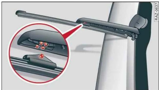
natural_image
Diagram of a mechanical device with a magnified inset showing internal components (no text or symbols)Fig. 45 Rear window wiper: installing the wiper blade
Cleaning the wiper blades
▶ Fold the wiper arm away from the rear window.
▶ For information on cleaning, see table on page 271.
Removing the wiper blade
▶ Fold the wiper arm away from the rear window.
- Remove the wiper blade from its holder.
Installing the wiper blade
▶ Press the wiper blade mount into the retainer.
▶ Fold the window wiper arm back onto the rear window.

WARNING
For safety reasons, the windshield wiper blades should be replaced once or twice each year.
Messages
If the 📄 indicator light turns on, then there is a windshield wiper malfunction. The displayed message indicates the cause and possible solutions. If one of the messages does not turn off, drive immediately to an authorized Audi dealer or authorized Audi Service Facility to have the malfunction repaired.

Automatic wipers: malfunction! See owner's nual
The light/rain sensor is malfunctioning. You can still control all functions that are independent of the rain sensor through the windshield wiper lever. Drive immediately to an authorized Audi dealer or authorized Audi Service Facility to have the malfunction repaired.
Digital compass
Switching the compass on and off
Applies to: vehicles with digital compass

Fig. 46 Rearview mirror: digital compass is switched on
To turn the compass on or off, press the button ① until the compass display in the mirror turns on or off.
The digital compass only works when the ignition is turned on. The directions are indicated with abbreviations: N (north), NE (northeast), E (east), SE (southeast), S (south), SW (southwest), W (west), NW (northwest).

Tips
To prevent inaccurate compass readings, do not bring any remote controls, electrical devices or metallic objects near the mirror.
Adjusting the magnetic zone
Applies to: vehicles with digital compass

heatmap
| Region | Value | | -------------- | ----- | | North America | 15 | | Europe | 14 | | Asia | 13 | | Africa | 12 | | South America | 11 | | Australia | 10 | | Oceania | 9 | | Middle East | 8 | | Central Europe | 7 | | Southeast Asia | 6 | | Eastern Europe | 5 | | Southern Europe| 4 | | Northern Europe| 3 | | Middle East | 2 | | Central Asia | 1 |Fig. 47 Magnetic zone map
The magnetic zone must be adjusted correctly for the compass to read accurately.
▶ Press and hold the button ① ⇔ page 56, fig. 46 until the number of the magnetic zone appears in the interior rearview mirror.
▶ Press the button ① repeatedly to select the correct magnetic zone. The selection mode turns off after a few seconds.
Calibrating the compass
Applies to: vehicles with digital compass
You must recalibrate the compass if it does not display the correct direction.
▶ Press and hold the button ① until a C
⇒ page 56, fig. 46 appears in the rearview mirror.
▶ Drive in a circle at about 6 mph (10 km/h) until a direction is displayed in the rearview mirror.

WARNING
To reduce the risk to yourself and other drivers, calibrate the compass in an area where there is no traffic.
Sitting correctly and safely
Correct passenger seating position
General information
As the driver, you are responsible for making sure every passenger is sitting correctly in their seat and maintaining this seating position while driving. Make sure that:
- Every passenger in the vehicle has adjusted his or her seat correctly page 58
- The steering wheel is adjusted correctly ⇒ page 62
- The mirrors are adjusted so that there is a sufficient view of the area around the vehicle ⇒ page 51
- Every passenger in the vehicle has his or her head restraint adjusted correctly page 63
- Every passenger in the vehicle has his or her safety belt fastened correctly page 64
- The activation status of the front passenger's airbag is suitable for the passenger in the front passenger's seat page 70
- Children are secured in suitable child safety seats that are secured to appropriate vehicle seats page 72. Read and observe the important safety information pertaining to the use of child safety seats on the front passenger's seat in General information on page 72.
Examples of incorrect seating positions
Safety belts can only provide its optimal protection when they are routed correctly. Incorrect seating positions significantly reduce the protective functions of the safety belts and increase the risk of injury due to incorrect belt routing.
The following list includes examples of seating positions that could be dangerous for all vehicle occupants. This is not a complete list. The purpose is to provide examples to increase your awareness of the topic. The following points apply when the vehicle is in motion:
– Never stand inside the vehicle.
– Never stand on the seats.
– Never kneel on the seats.
– Never tilt your backrest too far back.
– Never lean against the instrument panel.
- Never lie down on the rear bench seat.
- Never sit only on the front section of the seat.
– Never sit sideways on the seat.
– Never lean against the window.
– Never place your feet out of the window.
– Never place your feet on the instrument panel.
– Never place your feet on the seat cushion.
– Never ride in the footwell.
– Never sit on the armrests.
- Never drive or ride in a seat without fastening your safety belt.
– Never ride in the luggage compartment.

WARNING
Incorrect seating positions, failure to wear a safety belt, or being too close to an airbag increase the risk of serious or fatal injury to vehicle occupants, especially if the airbags deploy and come into contact with occupants who are not seated correctly. Note the important information and warnings in the chapters for the topics given above.

Tips
- Save your seat profile* page 67. This allows you to access your personal seat profile quickly and easily at any time.
- If you or other vehicle passengers have physical limitations that prevent sitting in a correct position, modifications to the vehicle may be necessary. For more information, contact an authorized Audi dealer or authorized Audi Service Facility, or call Audi customer support at 1-800-822-2834.
Front seats
General information
Make sure that:
- You can press the pedals down completely while your legs are slightly bent
- The distance between your upper body and the steering wheel or instrument panel is at least 10 inches (25 cm)
- The distance between your knees and the instrument panel is at least 4 inches (10 cm)
- Your thighs are lightly supported by the front surface of the seat
– The backrest is in an upright position and your back is resting against it - You have a sufficient view of the area around the vehicle
- You have a clear view of the instrument cluster, indicator lights, and the head-up display*
Seat settings menu: quick access
Applies to: vehicles with seat settings in the MMI
If you press on the image of the driver's or front passenger's seat in the climate control system menu page 87, fig. 84 ①, you will go directly to the seat settings for that seat.

WARNING
- If you are too close to the steering wheel or instrument panel, the airbag system cannot provide the optimal protection, which increases the risk of injury and death.
- To reduce the risk of injury in the event of sudden braking maneuvers or accidents, never drive with the backrest reclined very far. The airbag system and seat belts can only provide optimal protection when the backrest is in an upright position and the driver is wearing the seat belt correctly. If the backrest is angled back too far, the safety belt can shift to soft areas of the body, such as the stomach, which increases the risk of injury.
- To reduce the risk of an accident, only adjust the seats when the vehicle is stationary.
- Be careful when adjusting the seat. Lack of control or attention when adjusting can result in injuries due to pinching to vehicle occupants both in the front seats and rear seats.
- Never place objects in the driver's footwell. Objects could shift and enter the area around the pedals, which could prevent you from using them. You would then be unable
to use the pedals if sudden driving or braking maneuvers were needed, which increases the risk of an accident.
- Make sure that the floor mats are always securely attached.
- To reduce the risk of an accident, never place additional floor mats or other floor covers over the installed floor mats, because this reduces the pedal's range of motion and can impair pedal operation.
- To reduce the risk of injury, never place your feet on the instrument panel, out of the window, or on the seat surfaces. This also applies to passengers in the rear seats.

Note
To reduce the risk of damage, be very careful when adjusting the seat to make sure the head restraints do not come into contact with the headliner or the sunroof*.

Tips
At the same time, only move the respective seat using the controls.
Adjusting the front power seats
You can adjust the basic settings using the buttons.

Fig. 48 Front seat: seat adjustment buttons
The settings depend on the vehicle equipment.
Adjusting the seat position
▶ To adjust the seat forward or backward, push the button ① forward or backward.
▶ To adjust the seat upward or downward, push the rear section of the button ① upward or downward.
▶ To adjust the seat surface, press the front part of the button ① upward or downward.
Adjusting the backrests
▶ To adjust the backrest forward or backward, press the button ② forward or backward.
Adjusting the lumbar support
▶ To adjust the lumbar support, press the button ③ at the applicable location.
Massage function
Switch the massage function on or off ④. Setting the massage type and intensity page 60.

WARNING
The power front seats can also be adjusted when the ignition is switched off. To reduce the risk of injury, children should never be left unattended in the vehicle.
Adjusting the front seats in the MMI
Applies to: vehicles with seat settings in the MMI
You can adjust additional settings in the MMI.

flowchart
graph TD
    A["1 Car Seat"] --> B["2 Seatbelt Switch"]
    B --> C["3 Drive Mode"]
    C --> D["4 Drive Mode"]
    D --> E["5 Car Seat"]
    style A fill:#f9f,stroke:#333
    style B fill:#ccf,stroke:#333
    style C fill:#cfc,stroke:#333
    style D fill:#fcc,stroke:#333
Fig. 49 Upper display: seat setting
The settings and the number of menus and buttons depend on the vehicle equipment.
Operating
Applies to: MMI
▶ Select on the home screen: VEHICLE > Seats.
▶ To access the various menus ③, swipe to the left or right.
▶ To display the various seats, press > or < ④.
The red color of the symbol ⑤ indicates which seat is selected.
Seat adjustment
Applies to: MMI
▶ To select a seat setting, press ① if necessary.
▶ Press the respective arrow ② until the desired position is reached.
Massage
See page 60
Seat ventilation balance
Using the seat temperature balance, you can heat or cool the backrest and seat surface to different temperatures in Settings on page 89.
▶ To adjust the seat heating or cooling balance, slide the control upward or downward.
Additional seat settings
See page 61
Front seat massage function
Applies to: vehicles with massage function
Selecting the massage function
Applies to: MMI
▶ To access the Massage menu, press the button ④⇒ page 59, fig. 48.
Switching the massage function on or off
Applies to: MMI
▶ To switch the massage function on or off, press the ⚙④ ⇒ page 59, fig. 48 button. Or:
▶ Press Start/Stop on the MMI.
Setting the massage type and intensity
Applies to: MMI
▶ To adjust the massage type, press the desired button on the MMI, for example Wave.
▶ To adjust the intensity of the massage, press Intensity on the MMI repeatedly until the desired level is reached.

Tips
The massage function switches off automatically after approximately 10 minutes.
Additional settings in the MMI
You can adjust additional settings and switch functions on or off in the MMI.
▶ Applies to: MMI: Select on the home screen: VEHICLE > Seats > Additional seat settings.
Depending on the vehicle equipment, the following options may be available.
Reset seat position
You can adjust the position of the front passenger's seat to match the driver's seat.
Driver seat entry assistance/Front passenger seat entry assistance
Entry assistance makes it easier to enter or exit the vehicle.
Adjusting the front passenger's seat from the driver's seat
Applies to: vehicles with front passenger seat adjustment
You can adjust the front passenger's side with the driver's seat buttons.
Applies to: MMI:
▶ Select on the home screen: VEHICLE > Seats.
▶ To display the various seats, press > or <.
▶ To switch on the function, press the 📋 button. The lower edge of the button will turn red.
After you have switched on the function, you can adjust the front passenger's seat using the driver's seat buttons page 59, fig. 48.

Tips
The function switches off automatically when you exit the menu.
Front center armrest
Applies to: vehicles with a front center armrest

Fig. 50 Cockpit: center armrest
Adjusting the center armrest
▶ To slide the armrest forward or back, press the button ①.
▶ To adjust the angle, raise the armrest from the starting position in stages.
▶ To bring the armrest back into the starting position, raise it out of the top level and fold it back down.

WARNING
In certain positions, the front center armrest can interfere with the driver's arm movement, which increases the risk of injury.
Rear seats
General information

WARNING
- Be careful when adjusting the seat. Unsupervised or careless seat adjustment could cause parts of the body to get pinched, which increases the risk of injury.
- Always pull forward on the backrest to make sure it is check if it is correctly locked in place.
- To reduce the risk of an accident, only adjust the seat when the vehicle is stationary.
Adjusting the seats
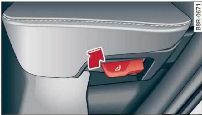
natural_image
Close-up of a car's rear seat and dashboard with a red arrow pointing to the side panel (no text or symbols visible)Fig. 51 Adjusting the backrests
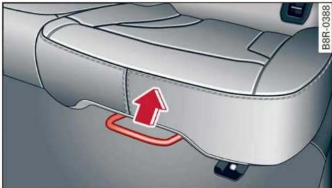
natural_image
Interior view of a car seatbelt with a red arrow pointing to the side panel (no text or symbols)Fig. 52 Adjusting the seat position
The settings depend on the vehicle equipment.
Adjusting the backrests
- Secure the backrest with one hand and pull the lever upward fig. 51.
▶ Move the backrest forward or back to the desired position.
▶ Release the lever and continue moving the backrest until it locks into place.
Adjusting the seat position
▶ To adjust the seat forward or back, pull the handle fig. 52 and slide the seat.
▶ Release the handle and continue sliding the seat until it locks into place.
Steering wheel
General information
Make sure that:
-
The distance between your upper body and the steering wheel is at least 10 in (25 cm)
– Your arms are bent slightly at the elbows -
You have a sufficient view of the area around the vehicle and you have a clear view of the instrument cluster and head-up display*.
- You are always holding the steering wheel with both hands on the outer edge at the sides (9:00 and 3:00 position) when driving

WARNING
- To reduce the risk of an accident, make sure the steering wheel is adjusted correctly and cannot be moved out of position before you start to drive.
- If you are too close to the steering wheel, the driver's airbag cannot provide optimal protection, which increases the risk of injury or fatality.
- Never hold the steering wheel in the 12:00 position or in any other way, such as holding the center of the steering wheel. Otherwise, your arms, hands, and head could be injured in the event that the driver's airbag deploys.
Power steering wheel position adjustment
The steering wheel position can be adjusted electrically up/down and forward/back.

natural_image
Close-up of a car's front wheel and dashboard with a red knob (no visible text or symbols)Fig. 53 Steering column: switch for adjusting the steering wheel position
▶ To move the steering wheel upward or downward, press the switch upward or downward.
▶ To move the steering wheel forward or backward, press the switch forward or backward.
The steering wheel can also be adjusted when the ignition is switched off.
In vehicles with memory function, the steering column settings are stored together with the seat position.

Tips
Entry assistance makes it easier to enter or exit the vehicle by moving the steering wheel → page 61, Driver seat entry assistance/ Front passenger seat entry assistance.
Head restraints
General information
Applies to: vehicles with adjustable head restraints
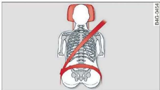
natural_image
Human skeletal and hip joint diagram with red belt indicating pressure or pressure direction (no text or labels)Fig. 54 Correctly-adjusted head restraint
Make sure that:
- The upper edge of the head restraint is as even as possible with the top of your head
- The head restraint is as close as possible to the back of the head
- The head restraints on rear seats that are occupied are raised up at least one level.

WARNING
- There is one head restraint for each seat. All vehicle occupants must adjust the head restraint correctly before every trip. Having head restraints that are not adjusted correctly or not installed in the vehicle increases the risk of a neck injury during sudden or unexpected driving or braking maneuvers or in a collision.
- Only remove the rear seat head restraints if it is necessary to install a child safety seat page 72. Stow the removed head restraints securely, for example in the luggage compartment. Reinstall the head restraints immediately once the child safety seat has been removed. Driving without head restraints increases the risk of serious neck injuries.
Front head restraints
Applies to: vehicles with adjustable head restraints
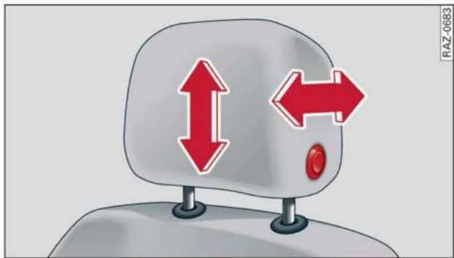
Fig. 55 Front seat: adjusting the head restraint
Adjusting the head restraints
▶ To adjust the head restraint upward, slide it until it locks into place.
▶ To adjust the head restraint downward or backward, press the button on the side and slide the head restraint. Release the button and slide the head restraint farther until it locks into place.
Rear head restraints
Applies to: vehicles with adjustable head restraints

Fig. 56 Rear seat: adjusting or removing the head restraint
Adjusting the head restraints
▶ To adjust the head restraint upward, slide it until it locks into place.
▶ To adjust the head restraint downward, press the button ② and slide the head restraint. Release the button and slide the head restraint farther until it locks into place.
Removing the headrests
Applies to: vehicles with removable head restraints
Applies to: vehicles with folding backrests: Fold the backrest forward slightly. See page 81.
▶ Move the head restraint upward all the way.
Insert a suitable object, such as the extended vehicle key or mechanical key, into the release point ① on the inside or outside of the base.
▶ Press the button ② and pull the head restraint out of the backrest ⇒ ⚠ in General information on page 63.
Installing the headrests
Applies to: vehicles with removable head restraints
▶ Fold the backrest forward slightly page 81.
▶ Slide the posts on the head restraint down into the guides until the posts click into place.
▶ Press the button ② and slide the head restraint all the way down. It should not be possible to remove the head restraint from the backrest without pressing the button.
Safety belts
General information
Each seat is equipped with a three-point safety belt. Safety belts that are worn correctly are the most effective way to reduce the risk of serious or fatal injuries in a collision. Therefore, wear your safety belt correctly and make sure that all vehicle passengers are also wearing their safety belts correctly when the vehicle is moving.
Even though your vehicle is equipped with an airbag system, every vehicle passenger must still always wear the appropriate safety belt. In addition to their normal protective function, safety belts also hold vehicle occupants in the correct seating position in the event of a collision so that the airbags can deploy correctly and provide additional protection. Safety belts provide protection during collisions when the airbags do not deploy or if they have already deployed.

WARNING
The risk of serious or fatal injury increases if the safety belt is not fastened, if it is worn incorrectly, or if it is damaged.
- All vehicle occupants, including the driver, must fasten their safety belts correctly before every trip and must always keep their safety belts fastened during the trip, regard-
less of whether the seat is equipped with an airbag or not. This also applies to children that are seated in a child safety seat that is appropriate for their weight and age and that is secured with a safety belt.
- In the event of a collision, vehicle occupants that are not wearing safety belts could be propelled through the vehicle interior and collide with vehicle components, such as the steering wheel, instrument panel, windshield, or doors. In some situations, vehicle occupants could also be ejected from the vehicle. Vehicle occupants in the rear seats who do not wear safety belts not only endanger themselves, but also other people in the vehicle.
- Only one person may be fastened with a safety belt at a time. Never secure more than one person, including children, with a single safety belt.
- Never allow children or infants to ride on another person's lap and be belted into the safety belt with them.
- Insert the belt buckle only in the belt latch belonging to the corresponding seat, so that the protective function is not impaired.
- To ensure the maximum protective function of the safety belts, all vehicle passengers must sit in the correct seating position page 58.
- Check the condition of your vehicle's safety belts regularly page 271. If you find damage to the belt webbing, the belt connections, the retractor, or the buckle, have the damaged safety belt replaced by an authorized Audi dealer or authorized Audi Service Facility.
- The safety belts must not be removed or modified in any way. Do not attempt to repair the safety belts yourself.
- Safety belts that are strained during an accident, and thus stretched, must be replaced by an authorized Audi dealer or authorized Audi Service Facility.
Correct safety belt positioning

Fig. 57 Lap/shoulder belt positioning

natural_image
Illustration of a person seated in a car steering wheel, wearing a red belt and white head cover (no text or symbols)Fig. 58 Safety belt positioning for pregnant women
Fastened safety belts only offer optimal protection during an accident and reduce the risk of serious injury or death when they are positioned correctly. Furthermore, the correct safety belt position holds the vehicle occupant in place so that a deployed airbag can provide maximum protection. Therefore, always fasten the safety belt and make sure it is positioned correctly fig. 57.
To ensure the safety belt is positioned correctly, make sure of the following points:
- The lap portion of the safety belt must be located across the lap.
- The shoulder portion of the safety belt must rest over the center of the shoulder.
– The safety belt must always rest flat and securely on the body.
For pregnant women, the safety belt must rest evenly across the chest and as low and flat as possible on the lap, so that no pressure is applied to the lower abdomen. This should be done throughout the entire pregnancy fig. 58.

WARNING
Incorrect safety belt positioning can cause serious injury in the event of an accident or during sudden braking or driving maneuvers.
- Never drive with the backrest reclined extremely far. The more the backrest is tilted back, the greater the risk of injury due to the safety belt being routed incorrectly.
- The safety belt itself or a loose safety belt can cause serious injuries if it shifts onto soft areas of the body, such as the stomach.
- The shoulder portion of the safety belt must lie over the center of the shoulder and chest, and never under the arm, behind the back, or across the neck or face.
– The lap portion of the safety belt must lie across the lap and never over the stomach. - The safety belt must lie flat and securely on the upper part of the body and the lap.
- The belt webbing must not be pinched or twisted, or rub against sharp edges.
- If the safety belt height is set incorrectly and/or the safety belt is routed incorrectly, then the safety belt's protective function will be impaired in the event of an accident. Make sure the safety belt is at the right height and is routed correctly for the passenger using it.
- A safety belt that is too loose may lead to injuries during an accident, because your body will move farther forward due to kinetic energy and will be stopped abruptly by the belt.
- Heavily bulky, loose clothing (for example, a coat over a sports jacket) may prevent the seat and safety belts from functioning correctly.
- Do not position the safety belt over hard or breakable objects (such as glasses, pens, etc.).
- The lap belt portion of the safety belt must sit as low as possible on the lap of pregnant women and lie flat under the belly.

Note
Make sure that there are no hook-and-loop fasteners or sharp objects such as zippers or
rivets on clothing in the area where the safety belt is worn. Otherwise, the safety belt could be damaged.
Fastening and unfastening safety belts

natural_image
Illustration of a hand holding a red belt buckle with a red arrow indicating force or pressure (no text or symbols)Fig. 59 Belt buckle and belt latch
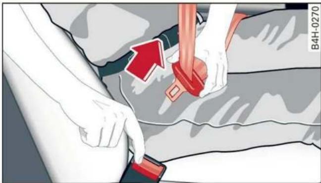
Fig. 60 Releasing the belt buckle from the belt latch
Follow the safety precautions page 64.
Fastening the safety belt
▶ Pull the safety belt by the belt buckle evenly across your chest and lap.
▶ Insert the belt buckle in the belt latch belonging to the seat until it audibly engages
⇒ fig. 59.
▶ Pull on the belt to make sure that the belt is securely locked in the latch.
Unfastening the safety belt
▶ Press the red button on the belt latch fig. 60.
The belt buckle will pop out.
▶ Guide the belt back by hand so that the safety belt can roll up more easily.
Safety belt monitoring system
- If the indicator light turns on or flashes, a safety belt is not fastened or it has been unfas-
tened while the vehicle is in motion. Above certain speeds, additional warning tones will sound.
Depending on the equipment, the safety belts in the rear may also be monitored using the following indicator lights:
- If this indicator light turns on, the safety belt for the corresponding rear seat is not fastened.
- If this indicator light turns on, the safety belt for the rear seat has been fastened.
- If this indicator light turns on with a white light, the safety belt for the rear seat has been fastened. If the indicator light flashes or turns gray, a safety belt in the rear is not fastened or has been unfastened while the vehicle is in motion.
Adjusting the height of the safety belt

Fig. 61 Belt height adjustment for the front seats - safety belt relay
▶ To move the belt higher, slide the safety belt relay ② upward.
To move the belt lower, press the release button ① and slide the safety belt relay ② downward.
▶ To check if the safety belt relay is securely locked in place, pull firmly on the belt.
i Tips
You can also adjust the height of the front seats to change the position of the safety belts.
Additional safety belt functions
Belt retractor lock
The safety belts on the rear seats and on the front passenger seat are equipped with a belt retractor lock.
▶ If you secure a child safety seat with a safety belt, the belt retractor lock on the safety belt may need to be activated. Follow the instructions from the child safety seat manufacturer.
- When a vehicle passenger has fastened a safety belt, the belt retractor lock should not be activated. If the belt retractor lock has been activated unexpectedly, deactivate it.
Deactivating or activating the belt retractor lock ⇒ page 75.
Safety belt retractor
The safety belts are equipped with an automatic belt retractor. This automatic retractor allows the safety belt to be pulled all the way out when the belt is pulled slowly. However, the automatic retractor locks during sudden braking maneuvers. It also locks the belts when accelerating, driving uphill, and driving around curves.
Belt force limiter
Safety belts with belt force limiters reduce the force placed on the body by the safety belts during a collision.
Safety belt pretensioners
Safety be belt tensi tain drivir loose it v
tem must be replaced by an authorized dealer or authorized Audi Service Facilit
i Tips
Smoke may be released when pyrotechn tensioners deploy. This is not a sign of a cle fire.
Memory function
General information
Applies to: vehicles with memory function
With the memory function, you can save up seat profiles using the memory button door trim panel.
Depending on the equipment, it may be p to store the following settings:
- Driver's seat: seat, steering wheel*, ext mirrors
- Front passenger's seat: seat
Storing and recalling a seat profile
Applies to: vehicles with memory function
The memory function buttons are located door trim panel.
Storing a seat profile
▶ Press the SET button. If the LED in the turns on, a seat profile can be stored.
▶ Push one of the numbered memory but tone confirms that the settings were st
loosen. This reduces forward movement by the vehicle passengers.
! WARNING
The pyrotechnic system can only provide protection during one collision. If the pyrotechnic belt tensioners deploy, the pretensioning sys-
or the ignition is switched on, press and hold the memory button until the seat profile is completely set.
! WARNING
- To reduce the risk of an accident, the seat setting can only be recalled when the vehicle is stationary.
- In an emergency, the recall process can be canceled by pressing the seat adjustment button on that seat.

Tips
Certain settings are stored automatically in the active personal profile.
Airbag system
General information

WARNING
- If you have not fastened your safety belt, you are in an incorrect seating position, or you are too close to the airbag system, the airbag system will not be able to protect you. This increases the risk of serious or fatal injuries. Make sure that every vehicle passenger has their safety belt correctly fastened and is sitting in a correct seating position page 58. This is necessary regardless of whether the seat is equipped with an airbag or not.
- Never place your feet on the instrument panel, out of the window, or on the seat surfaces. To help ensure that the airbag system can deploy correctly, never bend forward or lean on the door or the side window. Otherwise, serious and possibly fatal injuries can occur if the airbags deploy.
- People, animals, or objects between the passengers and the airbag system can interfere with the correct deployment of the airbag or can be thrown through the vehicle interior, increasing the risk of serious or fatal injuries. Make sure that nothing is located between the vehicle occupants and the airbag system. Do not secure or transport any objects within the deployment zone of the airbag systems, especially on the steering wheel, on the instrument panel, on the doors, on the windows, or in the footwell.
- Never put stickers on the airbag system covers or cover them with any objects.
- Only lightweight clothing should be hung from the garment hooks in the vehicle. Do not use clothes hangers to hang clothing.
The pockets of the clothing must not contain any heavy, breakable, or sharp-edged objects. This could impair the effectiveness of the side curtain airbags.
- You must not use seat or protective covers that are not specifically approved for use on Audi seats with side airbags. Since the side airbags deploy from the seat backrest, such covers could impair the protective function of the side airbags.
– Damage to the original seat covers in the side airbag deployment area must always be repaired by an authorized Audi dealer or authorized Audi Service Facility.
– Airbag system components are installed at various locations in your vehicle. Incorrect work or repairs on the vehicle could damage the airbag system components or impair their functionality. This may prevent the airbags from deploying or cause them to deploy incorrectly in the event of an accident, which increases the risk of serious or fatal injuries. Only have an authorized Audi dealer or authorized Audi Service Facility make repairs or modifications to a vehicle.
- The airbag system can only provide protection during one collision. If there is another collision, the airbag system will not deploy again. If the airbag system has deployed, have it replaced immediately by an authorized Audi dealer or authorized Audi Service Facility.
- Fine dust may appear if the airbags deploy. This is completely normal and does not indicate a fire in the vehicle. The fine dust can irritate the skin and mucous membranes in the eyes and can cause difficulty breathing, particularly for individuals who have or have had asthma or other health issues that affect breathing. Exit the vehicle or open the windows or doors to get access to fresh air.

Tips
If you are transporting children in the vehicle, read the information and follow the safety precautions page 72.
Safety systems monitoring
The indicator light in the instrument cluster monitors the safety systems such as the airbags (including the control modules, sensors, and wiring) and the belt tensioners. It turns on when you switch the ignition on and turns off after several seconds.
If the 📁 indicator light does not turn on when the ignition is switched on, does not turn off after several seconds, or turns on or flashes while
driving, there may be a malfunction in one of the safety systems. Drive to an authorized Audi dealer or authorized Audi Service Facility immediately to have the malfunction corrected.

WARNING
Have the malfunction in the safety systems inspected immediately. Otherwise, there is a risk that the systems may not activate during an accident, which increases the risk of serious or fatal injury.
Description

Fig. 62 Airbag overview image (enlarged section: deployed airbags)
The locations of the airbags are labeled with "AIRBAG". The following airbags are installed in your vehicle:
① Driver's airbag
② Front passenger's airbag
③ Front and rear side airbags, if applicable
④ Head curtain airbag with ejection mitigation
Airbags offer the best possible protection in your vehicle during an accident when they are used to-
gether with safety belts that are fastened correctly, and when passengers are sitting in the correct seating position. Airbags are a supplementary restraint system and do not replace safety belts.
Airbags may deploy during front-impact, side-impact, or rollover accidents.
The deployment area for the airbag system cannot be defined for every situation, since the circumstances surrounding accidents can vary
widely. Factors that play an important role include the condition of the object that the vehicle hits (hard or soft), the angle of impact, vehicle speed, etc. The deciding factor for the deployment of the airbag system is the deceleration that occurs during an accident. Sensors in the vehicle are designed to detect the severity of an accident in conjunction with the control module, and to provide a targeted and timely deployment of the restraint system. If the vehicle deceleration that is measured during an accident is below the specified reference values in the control module, then the airbags will not deploy, even though the vehicle may be severely damaged from the accident. In these cases, the vehicle occupants will be protected by the safety belts if they are fastened and worn correctly.
The deployment of the front passenger's airbag will depend on the occupancy of the seat page 70.
Each deployed airbag is filled with gas. When this occurs, the airbag covers open and the airbags unfold with great force into the deployment zone within milliseconds. Inflated airbags reduce the movement of passengers wearing safety belts in the direction of the impact and thus help to reduce the risk of injury. They can help to protect the head, upper body, and lap, for example. However, there is the possibility that airbag deployment can cause injuries.
The airbag system only works when the ignition is turned on.
If you or other vehicle passengers have physical limitations that prevent sitting in a correct position, modifications to the vehicle may be necessary. For more information, contact an authorized Audi dealer or authorized Audi Service Facility, or call Audi customer support at 1-800-822-2834.

Tips
The side curtain airbags in your vehicle have ejection mitigation functions. This reduces the risk of being ejected from the vehicle interior during an accident, especially in the event of a vehicle rollover.
Advanced airbag system
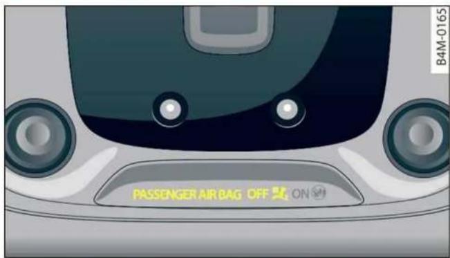
Fig. 63 Headliner: indicator light to display the status of the front passenger's airbag
The Advanced Airbag System in your vehicle has been certified to comply with the requirements of the United States Federal Motor Vehicle Safety Standard (FMVSS) 208, as well as Canada Motor Vehicle Safety Standard (CMVSS) 208 as applicable at the time your vehicle was manufactured. According to these requirements, the front Advanced Airbag System on the passenger's side has been certified for "suppression" for infants approximately 12 months old and younger, and for "low risk deployment" for children aged 3 to 6 years old (as defined in the standard).
The advanced airbag system will activate or deactivate the front passenger's airbag based on the occupancy of the seat. If a front airbag deploys during an accident, the deployment force will adapt to the passenger.
Components
The advanced airbag system consists of the following components:
- Front airbags in the steering wheel and in the instrument panel on the front passenger's side: these can protect the front passengers during an accident
- Passenger occupant detection sensor in the front passenger's seat: this detects if the front passenger's seat is occupied (for example, by a person or a small child in a child safety seat)
- Seat position sensors on the front seats: these determine the distance between the seat and the steering wheel or instrument panel
- Sensors in the front seat belt latch: these detect if the safety belts are fastened
- The PASSENGER AIR BAG OFF ON indicator light in the headliner: this indicates if the front passenger's airbag is activated or deactivated
- indicator light in the instrument cluster: this monitors the function of the Advanced Airbag System components to ensure they are functioning correctly
How the components function together
The passenger occupant detection sensor in the front passenger's seat detects if the front passenger's seat is occupied. The passenger occupant detection sensor measures the electrical capacity on the front passenger's seat. The passenger's airbag is activated or deactivated depending on the electrical capacity that is measured.
The passenger's airbag is activated if:
- The electrical capacity is higher than the threshold stored in the control module
- The electrical capacity is the same as or greater than the electrical capacity of a typical adult
The passenger's airbag is deactivated if:
- The electrical capacity is lower than the threshold stored in the control module
- The electrical capacity is the same as or less than the electrical capacity of a typical one-year-old child in a child safety seat that has been used for certification in accordance with FMVSS 208
If the front passenger's airbag is activated, the PASSENGER AIR BAG ON 🎨 indicator light will turn on. If the front passenger's airbag is deactivated, the PASSENGER AIR BAG OFF 🎨 indicator light will turn on.
The deployment force of the front airbags adapts based on whether or not the safety belt is used and the distance between the seat and the steering wheel/instrument panel. For example, if a person is too close to the front airbag, the front airbag will deploy with less force to help reduce the risk of injury.
Meaning of PASSENGER AIR BAG OFF ON indicator light
When the ignition is switched on, the system detects whether the front passenger's seat is occupied. PASSENGER AIR BAG OFF ON will turn on for several seconds during this process. Then it will indicate whether the front passenger's airbag is activated or deactivated.
- PASSENGER AIR BAG OFF ⚙₂: the front passenger's airbag is deactivated and will not deploy in the event of an accident.
- PASSENGER AIR BAG ON ⓤ: the front passenger's airbag is activated and could deploy in the event of an accident.
If a change to the occupancy status of the front passenger's seat is detected, PASSENGER AIR BAG OFF ON will flash for several seconds and will then display the status of the front passenger's airbag.
Always make sure the indicator light corresponds to the occupancy of the front passenger's seat.
- An adult or individual of similar size in the front passenger's seat: the front passenger's airbag must be activated, so PASSENGER AIR BAG ON Ⓜ must remain on.
- An individual of smaller size (for example, an adolescent or small adult) in the front passenger's seat: the front passenger's airbag must be activated, so PASSENGER AIR BAG ON Ⓜ must remain on.
- Child in a child safety seat on the front passenger's seat: the front passenger's airbag must be deactivated, so PASSENGER AIR BAG OFF ⚙₂ must remain on.
- Front passenger's seat not occupied: the front passenger's airbag must be deactivated, so PASSENGER AIR BAG OFF ⚡️ must remain on.

WARNING
- An adult or a person with a small stature (such as a young person or small adult) seated on the front passenger's seat will not be
protected by the passenger's airbag in the event of a collision if the passenger's airbag is deactivated. This increases the risk of injury and death. Always make sure that PASSENGER AIR BAG ON Ⓜ remains on while driving. If
PASSENGER AIR BAG ON ☑ does not turn on, make sure the front passenger is sitting correctly in the seat ⇒ page 58 and that there are no objects covering the front passenger's seat (such as blankets or pillows). If PASSENGER AIR BAG ON ☑ still does not turn on, the front passenger's seat must not be used. Drive to an authorized Audi dealer or authorized Audi Service Facility and have the airbag system inspected.
- A child in a child safety seat on the front passenger's seat - especially in a rear-facing child safety seat - can receive a severe impact if the front passenger's airbag deploys, which increases the risk of serious or fatal injury. Always secure child safety seats on the rear seats. If special circumstances require the use of a child safety seat on the front passenger's seat, always make sure that PASSENGER AIR BAG OFF ✗2 remains on while driving. If PASSENGER AIR BAG OFF ✗2 does not turn on, remove the child safety seat and install it again according to the child safety seat manufacturer instructions. If PASSENGER AIR BAG OFF ✗2 still does not turn on, the front passenger's seat must not be used. Drive to an authorized Audi dealer or authorized Audi Service Facility and have the airbag system inspected.
- Fluids, electronic devices, or mechanical damage on the front passenger's seat may cause the front passenger seat occupant detection to malfunction. The system may then incorrectly detect if the front passenger's seat is occupied. As a result, it could deploy the front passenger's airbag incorrectly or fail to deploy it, which increases the risk of serious or fatal injury. Make sure that no wet objects (such as a wet hand towel) and no fluids come into contact with the front
passenger's seat cushion. If the front passenger's seat becomes wet, dry it immediately. Make sure no electronic devices (such as a laptop or a retrofitted seat heater) are on the front passenger's seat. Do not transport any objects on or under the front passenger's seat.
- Seat covers or protective covers may prevent the advanced airbag system from correctly detecting child safety seats or passengers in the front passenger's seat. You must not use seat covers or protective covers on the front passenger's seat that are not specifically approved for use on Audi seats with an advanced airbag system.
Child safety seats
General information
When installing and using child safety seats, follow the information in this Owner's Manual, the applicable state and federal regulations, and the manufacturer instructions for the child safety seat.
You can also obtain useful and current information from the following sources:
U.S. National Highway Traffic Safety Administration
http://www.nhtsa.gov
http://www.safercar.gov
National SAFE KIDS Campaign
http://www.safekids.org
SafetyBeltSafe U.S.A.
http://www.carseat.org
Transport Canada Information Centre
http://www.tc.gc.ca/roadsafety
Audi Customer Experience Center
https://www.audiusa.com/help/contact-us https://www.audi.ca/ca/web/en/models/layer/contact.html
! WARNING
To reduce the risk of serious or fatal injuries, children must always be secured in the vehicle
with a child safety seat that is appropriate for their body size, weight, and age.
– Children ages 12 and under must be transported using the appropriate child safety seat. Note differences in regulations between states and countries.
– Child safety seats secured incorrectly in the vehicle may cause serious or fatal injuries in the event of an accident. Always secure the child safety seat according to the manufacturer instructions.
– Children or babies must not under any circumstances be held on the lap of the driver or other passengers while driving.
- Do not secure more than one child in a child safety seat.
- Never allow a child to sit in a child safety seat unsupervised.
- Never allow children to ride unsecured in the vehicle or to stand or kneel on the seats while driving. In the event of an accident, a child could be propelled through the vehicle. This can cause serious or fatal injuries for the child and passengers.
- If children use an incorrect seating position while driving, they have a higher risk of injury during a sudden braking maneuver or accident. This especially applies to children in the front passenger's seat or children who have their head near the side airbag deployment area, if the airbag system is deployed during an accident. This incorrect seating position can cause severe or even fatal injuries.
- Make sure there is enough space in front of the child in the child safety seat. If necessary, adjust the angle and position of the seat in front of the child safety seat.
- The rear side of a forward-facing child safety seat should be positioned as close as possible to the backrest on the vehicle seat. If the head restraints make it difficult to install a child safety seat, adjust or remove them if necessary page 63. Reinstall the head restraints immediately once the child safety seat has been removed.
- Always make sure that the backrest on the seat where the child safety seat is installed
is securely locked in place and cannot move forward. Otherwise, the backrest where the child safety seat is secured could move forward in the event of an accident or other emergency situation.
- NEVER use a rear-facing child safety seat on a seat with an ACTIVATED FRONT AIRBAG; this could cause DEATH or SERIOUS INJURIES to a CHILD.
- Always secure child safety seats on the rear seats. If exceptional circumstances require the child safety seat to be placed on the front passenger's seat, then the front passenger's airbag must be deactivated. Always make sure that
PASSENGER AIR BAG OFF ×2 remains on while driving. If
PASSENGER AIR BAG OFF ✉ 2 does not turn on, remove the child safety seat and install it again according to the child safety seat manufacturer instructions. If PASSENGER AIR BAG OFF ✉ 2 still does not turn on, the front passenger's seat must not be used. Drive to an authorized Audi dealer or authorized Audi Service Facility and have the airbag system inspected.
- If you must use a forward-facing child safety seat on the front passenger's seat, move the seat as far back as possible so that it is as far as possible from the front passenger's airbag. While doing this, make sure the seat can be adjusted all the way. A child in a child safety seat on the front passenger's seat can receive a severe impact if the front passenger's airbag deploys, which increases the risk of serious or fatal injury.
- Replace the child safety seat after an accident because there could be damage that is not visible.
- Even if a child is not sitting in the child safety seat, the child safety seat must be secured. An unsecured child safety seat may be thrown through the vehicle interior during sudden braking maneuvers or an accident.
Correct positioning for children
Always secure children in a child safety seat designed for the body size, weight, and age of the child.
You can secure child safety seats in your vehicle using the lower LATCH anchors or the safety belts. You can also secure child safety seats to the top tether anchor. Depending on the child safety seat, it may also be necessary to secure it to the top tether anchor. In Canada, securing forward-facing child safety seats to the top tether anchors is required by law.
Always transport children in the rear seats
Accident statistics show that children that are secured correctly in the rear seats are safer than in front seats. Always transport children in suitable child safety seats secured on the rear seats.
In exceptional circumstances: transporting children in the front passenger's seat
If exceptional circumstances require the child safety seat to be placed on the front passenger's seat, then the front passenger's airbag must be deactivated. Please note the important information for this page 70, Advanced airbag system. If you must secure a forward-facing child safety seat, move the front passenger's seat as far back as possible so that it is as far as possible from the front passenger's airbag. While doing this, make sure the seat can be adjusted all the way.
Only switch to a larger child safety seat when absolutely necessary
Switch to a larger child safety seat only when absolutely necessary. Secure your child using a safety belt without a child safety seat only if all of the following statements are true:
– The child is large enough to sit upright in the seat
– The child is able to sit with his or her back resting completely on the seat backrest
- The child is able to sit with his or her knees bent over the edge of the seat surface
- The child is able to sit with both of his or her feet completely touching the floor in the foot-well
- The lap portion of the safety belt lies flat and securely over the hip area and never over the stomach
- The shoulder portion of the safety belt lies flat and securely over the center of the shoulder and the chest, and never under the arm, behind the back, or over the neck or face.
– The child is able to maintain this seating position throughout the entire trip
Read and follow the important information and warnings regarding the correct use of safety belts page 64.
i Tips
- Child safety seats can also be secured to seats with side airbags. In the event of an accident, children can also be protected by the side airbags if the child is correctly secured in a suitable child safety seat that is attached correctly.
- The lower LATCH anchors as well as the safety belt may be required to correctly install some child safety seats. Using both at the same time is permitted, provided that the fastening systems or safety belts do not impair those in an adjacent seating position.
– All child safety seats are constructed so that they can be secured using the lap safety belt in the vehicle.
– Child safety seats with a support base can only be secured to the outer rear seats and to the front passenger's seat.
Securing child safety seats to the lower LATCH anchors
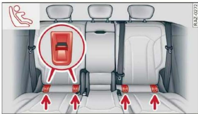
Fig. 64 Rear bench seat: lower LATCH anchors
Follow the safety precautions page 72.
In the United States and Canada, child safety seats can be secured without safety belts using the LATCH system. LATCH stands for Lower Anchors and Tethers for Children. In Canada, similar systems are called UCRA, LUAS, or UAS.
The lower LATCH anchors in your vehicle are located on the outer seats of the rear bench seat between the seat surface and the backrest. These seating locations each have two lower LATCH anchors that can be used to secure a LATCH child safety seat. Marking points with a fig. 64 symbol are located on the covers for the lower LATCH anchors. You can locate the LATCH anchors using the marking points.
- Applies to: vehicles with forward/back adjustable rear bench seat: Move the rear seat all the way back.
▶ Activate the child safety lock page 41. - Remove the cover from both lower LATCH anchors.
▶ If you secure a child safety seat to the rear seat, secure any unused safety belts that are within reach of the child ⇒ ⚠ in Securing child safety seats with a safety belt on page 76. - Secure the child safety seat according to the child safety seat manufacturer instructions.
▶ Pull on the child safety seat to check if both sides are engaged correctly in the LATCH anchors.
▶ If possible, also secure the child safety seat to the respective top tether anchor on the seat page 76.

WARNING
The LATCH anchors in the vehicle are only designed for child safety seats with the LATCH system. To reduce the risk of serious or fatal injury, never secure other child restraint systems, belts, or objects to the anchors.

Tips
The LATCH anchors are designed for a total weight (child and child safety seat combined) up to 65 lbs (29 kg). If the total weight is greater than this, the child safety seat must be secured with the vehicle safety belt.
Securing child safety seats with a safety belt
Follow the safety precautions page 72. The front passenger's seat is a dangerous location for a child, even with an advanced airbag system. If exceptional circumstances require the child safety seat to be placed on the front passenger's seat, then the front passenger's airbag must be deactivated. Please note the important information for this page 74, Correct positioning for children and page 70, Advanced airbag system.
Securing child safety seats
- Applies to: vehicles with forward/back adjustable rear bench seat: Move the rear seat all the way back.
▶ Activate the child safety lock page 41.
▶ If you secure a child safety seat to the rear seat, secure any unused safety belts that are within reach of the child !, page 77.
▶ If you secure a child safety seat to the front passenger's seat, adjust the front passenger's seat to the highest position. - Secure the child safety seat according to the child safety seat manufacturer instructions.
▶ If necessary, activate the belt retractor lock ⇒ page 75, Activating the belt retractor lock.
▶ If the child safety seat is secured on the front passenger's seat, adjust the front passenger's seat backrest until it rests flat against the child safety seat. Also make sure that the upper safety belt fixture is behind the child safety seat.
▶ If you secure a child safety seat on the rear seat, also secure it to the correct top tether anchor if possible page 76.
Activating the belt retractor lock
If you secure a child safety seat using the vehicle safety belt, you must activate the belt retractor lock. Follow the child safety seat manufacturer instructions.
The belt retractor lock prevents the safety belt from becoming loose while driving, which could result in the child safety seat no longer being adequately secured.
- Secure the child safety seat according to the child safety seat manufacturer instructions. While doing so, pull out the safety belt. Insert the safety belt into the belt latch that belongs to that seat until it audibly locks.
▶ Pull the upper belt out completely and then allow it to retract. You will hear a clicking sound while the belt is retracting. It will not be possible to pull the safety belt out any farther.
▶ Push the child safety seat into the seat and allow the belt to retract more.
▶ Make sure that the child safety seat cannot move more than 1 inch (2.5 cm).
Deactivating the belt retractor lock
▶ Unbuckle the safety belt from the belt latch.
- Remove the child safety seat according to the manufacturer instructions.
▶ Allow the safety belt to retract completely. The belt retractor lock is deactivated.

WARNING
- A safety belt that is not locked by the belt retractor lock or a locking device cannot secure a child safety seat while driving or in the event of an accident, which increases the risk of fatal injury. Always make sure the belt retractor lock on the safety belt is activated if the child safety seat manufacturer instructions require it.
- Due to the risk of fatal injury, never place a rear-facing child safety seat on the front passenger's seat when the front passenger's airbag is switched on.
- For the child safety seat to offer the maximum protection, it is especially important to route the vehicle safety belt correctly. Always follow the instructions from the child safety seat manufacturer for routing the safety belt correctly. Incorrectly fastened safety belts can cause injuries, even during minor accidents.
Additionally securing a child safety seat to the top tether anchor
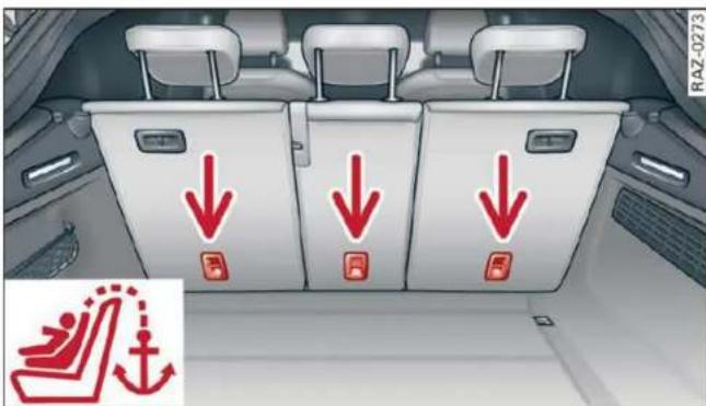
Fig. 65 Rear backrest: top tether anchors to secure a child safety seat with an upper belt

natural_image
Side view of a car seat with red belt and blue gait, no visible text or symbolsFig. 66 Rear backrest: securing the upper belt to the top tether anchor
Follow the safety precautions page 72.
There is a top tether anchor behind every seat in the rear bench seat to additionally secure a child safety seat with an upper belt.
▶ Move the head restraint behind the child safety seat upward.
- Secure the child safety seat according to the child safety seat manufacturer instructions.
▶ Guide the upper belt on the child safety seat under the head restraint or along both sides of it and toward the rear (depending on the child safety seat model).
▶ Fasten the belt to the top tether anchor
⇒ fig. 66. While doing this, make sure the belt is not twisted and is not running over any sharp edges.
▶ Pull the belt tightly so that the child safety seat rests at the top of the seat backrest.
▶ If necessary, move the head restraint behind the child safety seat downward.

WARNING
The top tether anchors in the vehicle are only designed for child safety seats equipped with an upper strap. To reduce the risk of serious or fatal injury, never secure other child restraint systems, belts, or objects to the anchors.
Securing unused safety belts on the rear bench seat
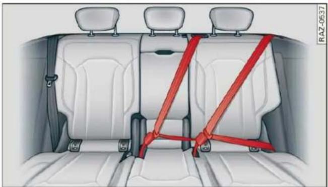
natural_image
Interior view of a car showing rear seats and rear seats with red safety belt (no text or symbols)Fig. 67 Rear bench seat: securing unused safety belts
If a child safety seat is used on the rear bench seat, the child must not be able to reach any safety belts that are not being used. Secure safety belts that are within reach of the child.
▶ If you secure a child safety seat to the LATCH anchors, fasten the safety belt on the seat where the child safety seat is installed using the seat's safety belt latch.
▶ If you secure a child safety seat to one of the outer seats, fasten the safety belt for the center seat in its latch.
▶ Activate the belt retractor lock on the fastened safety belts. To do this, pull the upper belt out completely and then allow it to retract. You will hear a clicking sound while the belt is retracting. It will not be possible to pull the safety belt out any farther.
▶ Make sure the fastened safety belt does not block access to the LATCH anchors. Otherwise, it may not be possible to secure the child safety seat to the LATCH anchors correctly.
fatal injury. Always secure unused safety belts so that they are not within reach of children in child safety seats.

WARNING
A child in a child safety seat could play with the unused safety belts and then become entangled in them, which increases the risk of
Stowing and using
Power sources
When the ignition is switched on, you may be able to use multiple power sources for external devices, depending on the vehicle equipment.
12 volt sockets
You can connect electrical accessories to the 12 volt sockets. The power usage must not exceed 120 watts.
The 12 volt sockets are labeled with the 12V symbol. They are located in the front center console, in the rear* and on the side trim panel in the luggage compartment*.
USB ports
Applies to: vehicles with USB input
You can charge mobile devices using the USB ports. The USB ports are labeled with the 🔊 or ➕ symbol or CHARGE ONLY.

WARNING
- To reduce the risk of fatal injury, store all connected devices securely when driving so that they do not move around inside the vehicle when braking or in the event of an accident.
- Incorrect usage can lead to serious injuries or burns. To reduce the risk of injuries, never leave children unattended in the vehicle with the vehicle key.

Note
- Read the operating manuals for the connected devices.
- To reduce the risk of damage to the vehicle electrical system, never attempt to charge the vehicle battery by connecting accessories that provide power to the power sources.
- Do not connect any device whose network class (voltage) does not match the network class designed for the socket.
- Disconnect the connectors from the power sources carefully to reduce the risk of damaging them.

Tips
Do not connect any other devices to the sockets when using the compressor* provided by the factory page 276. The power consumption in the sockets may be temporarily exceeded when using the compressor*.
Cup holders
Applies to: vehicles with cup holders

natural_image
Interior view of a car gear shift lever with red plastic housing and control buttons (no text or symbols visible)Fig. 68 Front center console: cup holder

natural_image
Interior view of a car seat with a red plastic tray and labeled component (no text or symbols beyond the label)Fig. 69 Rear center armrest*: cup holders
Front center console cup holders
The cup holder ① may be under a cover. To open the cup holder, tap on the strip on the cover.
Rear center armrest\* cup holders
▶ Fold the center armrest* downward.
▶ To open the cup holder, tap on the button ②.
▶ To close the cup holder, fold the cover back until it clicks into place.

WARNING
- Do not put any hot beverages in the cup holder while the vehicle is moving. Hot beverages could spill, which increases the risk of injury.
- Do not use any breakable beverage containers (for example, made out of glass or porcelain). You could be injured by them in the event of an accident.

Note
Beverage containers in the cup holders should always have a lid. Otherwise, the liquid inside could spill and cause damage to vehicle equipment.
Storage and compartments
Additional storage
Depending on the vehicle equipment, there may be a variety of storage areas, compartments, and retainers at various locations in the vehicle.
- Glove compartment: the glove compartment can be locked using the mechanical key page 35.
- Holders for a notepad and a pen in the glove compartment
- Storage compartment in the cockpit on the driver's side
- Storage compartments in the door trim panel
– Key compartment in the front center console
- Storage compartment under the front center armrest
– Nets on the back of the front seats
– Garment hooks in the rear
- Storage compartment in the rear center arm-rest
- Bag hooks in the luggage compartment
- Net in luggage compartment

WARNING
- To reduce the risk of injury, make sure all storage compartments are always closed while driving.
- Loose objects can be thrown around the vehicle interior during sudden driving or braking maneuvers, which increases the risk of an accident. Store objects securely while driving.
- Only use the storage compartments in the door trim panels to store small objects that will not stick out of the compartment and impair the function of the side airbags.
- Only lightweight clothing should be hung from the garment hooks in the vehicle. Do not use clothes hangers to hang clothing. The pockets of the clothing must not contain any heavy, breakable, or sharp-edged objects. This could impair the effectiveness of the side curtain airbags.
- Make sure your view toward the rear is not blocked, for example by hanging clothing or objects in the vehicle.
Luggage compartment
General information
All pieces of luggage or objects must be securely fastened in the luggage compartment. Note the following to maintain good vehicle handling:
▶ Distribute the load evenly in the luggage compartment.
▶ Stow heavy luggage as far forward in the luggage compartment as possible.
▶ Use non-elastic cords attached to the tie-downs to secure objects.

WARNING
- Applies to: vehicles with luggage compartment cover: The luggage compartment cover is not a surface for storing objects. Objects placed on the cover increase the risk of injury to all vehicle occupants during sudden driving or braking maneuvers or in the event of an accident.
- Loose objects can be thrown around the vehicle interior during sudden driving or braking maneuvers, which increases the risk of an accident. Always stow objects securely in the luggage compartment and secure them at the tie-downs. Use straps suitable for heavy objects.
- If pieces of luggage or objects are secured to the tie-downs with unsuitable or damaged straps, this can increase the risk of injury during braking maneuvers or accidents.
- When transporting heavy objects, the vehicle characteristics will change due to the shift in the center of gravity, which increases the risk of an accident. You may need to adapt your driving style and speed to the current conditions.
- The cargo net is only strong enough to secure light objects. Heavy objects are not adequately secured. Attempting to secure heavy objects increases the risk of injury.
- Never exceed the permitted axle and load and vehicle weight page 303.
- Never secure a child safety seat to the tie-downs.
- Never leave your vehicle unattended, especially if the luggage compartment lid is open. Children could enter the luggage compartment and close the luggage compartment lid from the inside. This creates the risk of fatal injury, since the children would be locked in and may not be able to escape by themselves.
- Do not allow children to play in or on the vehicle. Close and lock the luggage compartment lid as well as all other doors when you leave the vehicle.
- Never transport passengers in the luggage compartment. Every passenger must be correctly secured with the safety belts in the vehicle page 64.
- Be careful when releasing the backrest and folding it forward. To reduce the risk of being pinched, pay attention and check when folding backrests forward.
- The backrest must be securely latched so objects cannot slide forward out of the luggage compartment during sudden braking.
- The backrest must be latched securely to ensure that the safety belt is protecting the center seating position.
- Always pull forward on the backrest to make sure it is check if it is correctly locked in place.

Note
- To reduce the risk of damage, move the rear head restraints down page 63 before folding the rear backrests forward.
- When folding the backrest forward, make sure the outer safety belts are in the belt guide recess so that they do not get pinched in the backrest lock and damaged. Other objects should be removed from the rear bench seat to protect the backrest from damage.
- If you move the front seat back when the rear seat backrest is folded forward, you could damage the head restraints on the rear seat.
- Make sure that the heating grid strips for the rear window defogger are not damaged by abrasive objects.
- Let the luggage compartment cover roll up slowly to reduce the risk of damage.

Tips
- The tire pressure must be adapted to the load page 257.
- You can purchase straps at specialty stores.
Luggage compartment cover
Applies to: vehicles with luggage compartment cover

Fig. 70 Luggage compartment: cover extended (manual)

Fig. 71 Luggage compartment: removing the luggage compartment cover
Follow the safety precautions page 79.
▶ To pull the luggage compartment cover out, hold the handle ① on the cover and pull it toward the rear of the vehicle until it locks into place audibly at the ends of the guide rails ②.
▶ To retract the luggage compartment cover, lift it lightly and guide it slowly by hand toward the front of the vehicle without letting it retract quickly.
▶ To remove the luggage compartment cover, pull both levers ③ firmly in the direction of the arrow and remove the cover upward.
▶ To install the luggage compartment cover, place the cover in the mounts on the side trim panels on the left and right side.
▶ Push the cover downward until it clicks into place.
Rear lowering
Applies to: vehicles with air suspension

Fig. 72 Left side of the luggage compartment: rear lowering button
The rear of the vehicle can be lowered to make loading and unloading easier.
Requirement: all vehicle doors must be closed. The trailer mode for air suspension is switched off.
▶ Open the luggage compartment lid.
▶ Press the lower section of the button ①. The rear of the vehicle lowers.
▶ Press the upper section of the button ②. The rear of the vehicle will lift.
The LED in the button will turn on while the vehicle is lowering. When the loading level has been reached, the LED will stay on as long as the rear of the vehicle is in the lowered position. The LED turns off when the vehicle returns to the original level.
The rear of the vehicle will be automatically raised when you select another mode or start to drive.
Note
- Do not park the vehicle in a lowered loading level.
- Also refer to the information about ground clearance page 110.
i Tips
- The vehicle will not lower when the ignition is switched off if the compressed air reservoir is empty. The button LED blinks three times.
- If the compressed air reservoir is empty, it is refilled while driving at speeds above 25 mph (40 km/h).
Increasing the size of the luggage compartment
Applies to: vehicles with folding backrests

Fig. 73 Rear bench seat: release lever
The rear seat backrests can be folded forward either separately or together.
Follow the safety precautions page 79.
▶ If necessary, slide the rear bench seat forward
⇒ page 62.
▶ To fold the backrest forward, pull the release lever ① in the direction of the arrow.
▶ Fold the backrest forward until it locks into place.
▶ Pull the release lever to fold the backrest back.
▶ After the transport, fold the backrest up until it locks into place.
Pass-through
Applies to: vehicles with pass-through

Fig. 74 Center backrest: release button
Follow the safety precautions page 79.
▶ To fold the center backrest forward, press the release button ①.
▶ After the transport, fold the center backrest up until it locks into place.
Partition net
Applies to: vehicles with partition net

Fig. 75 Backrest folded forward: partition net
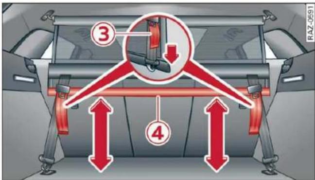
Fig. 76 Luggage compartment: partition net
The partition net prevents objects from sliding into the passenger compartment. You can attach the partition net behind the front or rear seats. Use the mounting eyelets ① or ② for this.
Follow the safety precautions page 79.
▶ Fold the backrest forward, if necessary
⇒ page 81.
▶ To attach the partition net, secure it in the upper mounting eyelets first, and then in the lower mounting eyelets.
▶ Tighten and secure the straps ③.
▶ Slide the lower section of the partition net to the desired level ④.
▶ To release the partition net, loosen the straps.
i Tips
- The straps must face toward the rear when attaching the partition net.
- The partition net can also be attached to the adjustable tie-downs* page 82.
- You must disengage the partition net before folding the backrest back into the upright position.
Tie-downs and cargo net
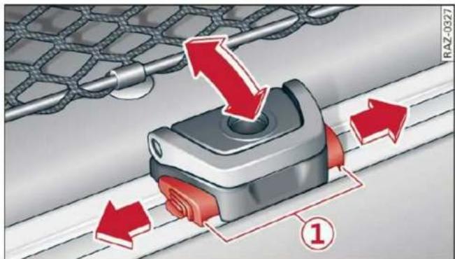
Fig. 77 Luggage compartment: movable tie-downs*
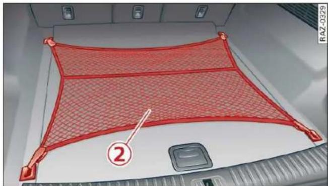
Fig. 78 Luggage compartment: luggage compartment net* stretched out
Follow the safety precautions page 79.
Tie-downs
There are tie-downs in the luggage compartment to secure pieces of luggage and objects.
▶ Use the tie-downs to secure the cargo.
Movable tie-downs
Applies to: vehicles with movable tie-downs
▶ To install the tie-downs, press both buttons at the sides ①, insert the tie-down in the rail, and lock it in place.
▶ To slide the tie-downs, press both of the side buttons and slide the tie-downs to the desired position. The tie-downs must lock in place.
▶ To remove the tie-downs, press both buttons at the sides and remove the tie-down from the rail.
Cargo net
Applies to: vehicles with luggage compartment net
Use the cargo net ② to secure lighter objects in the luggage compartment
▶ Fold the clip for the tie-downs upward.
- Attach the hooks for the cargo net to the tie-downs.
Fixture set
Applies to: vehicles with a fixture set
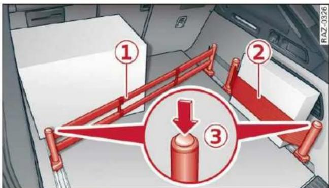
Fig. 79 Luggage compartment: securing attachments
The telescoping rod ① and the securing strap ② help to prevent objects from sliding around in the luggage compartment.
Follow the safety precautions page 79.
The fixture set is located in the openings under the cargo floor.
▶ Insert the movable tie-downs ⇒ page 83.
▶ Press the buttons ③ on the retainers and place them on the tie-downs. Make sure the brackets are locked into place.
▶ Slide the tie-downs into the desired position.
▶ Press the button to tighten the securing strap.
i Tips
Store the movable tie-downs and the fixture set in the openings under the cargo floor, if necessary.
Cargo mat
Applies to: vehicles with cargo mat

natural_image
Top-down view of a car trunk with red and white panels, no visible text or symbolsFig. 80 Luggage compartment: cargo mat
The cargo mat ① protects the luggage compartment and bumper from dirt and scratches.
Follow the safety precautions page 79.
▶ Extend the cargo mat lengthwise or crosswise.
▶ After loading or unloading, fold up the cargo mat and close the luggage compartment lid.
▶ Only store the cargo mat if it is dry.
i Tips
You can also use the folding cargo mat to partition the loading surfaces into separate sections.
Double cargo floor
Applies to: vehicles with double cargo floor

Fig. 81 Luggage compartment: cargo floor set up
You can store dirty or wet objects under the cargo floor.
Follow the safety precautions page 79.
▶ To set up the cargo floor, lift it by the handle ① and insert the edge of the cargo floor into the openings ②.
▶ To remove the cargo floor, pull the entire cargo floor out of the guides toward the rear of the vehicle.
▶ To install the cargo floor, first insert it into the guides and then slide it all the way in toward the backrest.

WARNING
Objects only up to a maximum of about 16.5 lbs (7.5 kg) may be transported under the cargo floor. To reduce the risk of injury, they must only be as tall as two-thirds of the height of the cargo floor when it is set up. Objects must be secured adequately.
Roof rack
General information
Applies to: vehicles with roof rack mount

Fig. 82 Roof rail: mounting points
If luggage or cargo is to be carried on the roof, you must observe the following:
- These roof racks are the basis for a complete roof rack system. Only roof racks that are suitable for your vehicle may be used. Roof racks and attachments from the Audi Genuine Accessories program are recommended.
- Make sure the roof rack is mounted on the vehicle only at the specified locations fig. 82.
- Note the permitted axle load, permitted total weight, and permitted roof load of your vehicle page 303. The roof load is the total of the weight of the roof rack, the attachments and the cargo you are carrying. However, you must also note the permitted load of the carrier system being used.

WARNING
- Follow the installation instructions provided with the roof rack system. If you do not secure the roof rack system and objects on the roof correctly, they could come loose from the vehicle and cause an accident.
-
The risk of an accident increases when using a roof rack system, because it changes the driving characteristics by shifting the center of gravity and/or the increasing the surface area exposed to wind. You may need to adapt your driving style and speed to the current conditions. Audi recommends that you do not drive faster than 80 mph (130 km/h).
-
Distribute the cargo evenly on the roof rack and do not exceed the maximum width or the maximum total roof load weight.
- Before every trip, all bolts and connections on the roof rack must be checked. Tighten them if necessary and recheck them regularly. If you do not do this, there is a higher risk of the roof rack or the attachments loosening or falling off.
Note
- If you use other roof luggage rack systems or do not install the roof racks as specified, then any damage to the vehicle is not covered by the warranty. Carefully follow the assembly and installation instructions included with the roof rack carrier system.
- To reduce the risk of damage, you must remove the roof rack and attachment before taking your vehicle through an automatic car wash.
- Make sure that the luggage compartment lid and the panoramic glass roof* do not come into contact with objects on the roof when they are open.
For the sake of the environment
Energy usage will increase because of the increased wind resistance. Remove the roof rack when you are no longer using it.
Installing the roof rack
Applies to: vehicles with roof racks supplied by the factory

Fig. 83 Roof rail: installing a roof rack
The roof rack set consists of a front and rear roof rack, the cover profile and a socket wrench. On the inner side of the roof rail, there are two holes for the rear roof rack. To prevent the front and rear roof racks from being switched during installation, there are three holes on the left inner side and two holes on the right inner side page 84, fig. 82.
▶ Before mounting the roof rack, open the cap ① upward.
▶ Use the socket wrench ② to loosen the left and right screw in the direction of Ⓐ until resistance is felt. Make sure the arrow on the socket wrench and the arrow on the screw line up exactly.
▶ Clean the rubber washers ④ and the roof rail around the mounting points.
▶ Carefully place the roof rack over the holes in the roof rail. Make sure the sticker is on the left side of the vehicle and the imprinted arrow points in the direction of travel.
- Place the pins ③ into the holes. The claw fastener ⑤ must engage into the edge of the roof rail. Make sure the rubber washers ④ lie flat on the roof rail.
▶ Tighten the screw in the direction of Ⓑ using the socket wrench. Make sure the arrow on the socket wrench and the arrow on the screw line up exactly. The required tightening specification is 4 ft lbs (6 Nm).
▶ Repeat these steps for the other mounting points for the roof rack.

WARNING
When installing a factory-supplied roof rack system on the roof rail, the ESC will use sensors to adapt itself to the different center of gravity if it changes because of carrying a load. This does not occur when using other roof rack systems, so the risk of an accident will increase.
Installing the attachments
Applies to: vehicles with roof racks supplied by the factory
Remove the cap ⑥ to mount attachments on the roof rack ⇒ page 85, fig. 83.
▶ Slide the attachment into the T-groove ⑦.
▶ Tighten the attachment according to the roof rack installation instructions.
▶ Close the cap ⑥.
Installing the cover profile
Applies to: vehicles with roof racks supplied by the factory
▶ After you have mounted the attachments, seal the openings in the T-groove ⑦ → page 85, fig. 83 with the cover profile ⑧. The cover profile must not be installed under the caps.
▶ If you do not want to use the attachment, seal the whole T-groove ⑦ with the cover profile ⑧.
▶ If necessary, shorten the cover profile ⑧ so that it matches the length of the open sections of the T-groove. The caps ⑥ must be closed.
Warm and cold
Climate control system
Description
One of the following options may be available, depending on vehicle equipment:
- A deluxe automatic climate control system with 3 zones where the temperature, air distribution, and air supply can be set separately on the left front side, the right front side, and in the rear
- A deluxe automatic climate control system with 4 zones to individually adjust the temperature, air distribution, and amount of ventilation at all of the seats
The climate control system warms, cools, dehumidifies, and filters the air in the vehicle interior. It is the most effective when the windows and panoramic glass roof* are closed. If there is a build-up of heat inside the vehicle, ventilation can help to speed up the cooling process.
The deluxe climate control system automatically maintains a temperature once it has been set. In all heating mode functions except defrost, the blower only switches to a higher speed once the engine coolant has reached a certain temperature.
Pollutant filter
The pollutant filter removes pollutants such as dust and pollen from the air.

For the sake of the environment
Energy can be saved by switching off the A/C mode.

Tips
- To prevent interference with the heating or cooling output and to prevent the windows from fogging over, the air intake in front of the windshield must be free of ice, snow, and leaves.
-
Condensation from the cooling system can drip and form a puddle of water under the vehicle. This is normal and does not mean there is a leak.
-
The energy management system may temporarily switch off certain functions, such as the seat heating* or rear window defogger. These systems are available again as soon as the energy supply has been restored.
- Certain settings are stored automatically in the active personal profile.
Operation

Fig. 84 Center console: lower display and switch panel
Settings are adjusted using both displays, the switch panel in the center console, and the control panel in the rear. For information on how to operate the touch displays, see page 17, Touch displays.
You can adjust all climate control system settings in the front; only certain functions are available in the rear.
Lower display
The lower display has two sections with controls:
You can regulate the blower and the air distribution automatically using AUTO in area ①. You can also apply individual settings here.
In area ②, you can switch individual climate control system functions on and off.
Switch panel in the center console
Both MAX and REAR buttons to defog windows as quickly as possible are located in area ③.
Upper display
In the upper display, you can switch additional functions on and off, display them, and adjust settings.
▶ Applies to: MMI: Select on the home screen:
VEHICLE > Air conditioning, or
▶ Select … on the lower display.
Control panel in rear
You can operate certain climate control functions in the rear using the control panel.
Customizing
A climate control function from the upper display can be assigned to each button to the left and right of … in area ②.
▶ Press and hold the symbol for the desired function on the upper display for at least three seconds. A menu that consists of two sections appears.
▶ If you pull the symbol toward the left section, the button to the left of ⋯ will be assigned.
▶ If you pull the symbol toward the right section, the button to the right of ⋯ will be assigned.
Settings
Press the buttons to turn the functions on or off. One bar in the button or the LED in the button will light up when the function is switched on. Some buttons can have several functions assigned to them. The various functions can be activated by pressing the button multiple times.
AUTO Automatic mode
The automatic mode regulates the amount of air and air distribution automatically, so that the set temperature is reached is quickly as possible.
REAR Rear climate control system
Applies to: vehicles with rear climate control system
To enable operation of the climate control system from the rear of the vehicle, press REAR.
To exit this mode again, press REAR or REAR MODE EXIT.
SYNC Synchronization
When synchronization is switched on, the temperature, air distribution, and blower strength on the driver's side is applied to all seat positions. You can also control the synchronization directly using a gesture. Pull two fingers together on the lower display page 17.
OFF Switching off
The climate control system is switched off. Air supply from the outside is blocked. If you press OFF in the front, the front and rear climate control system will switch off. If you press OFF in the rear, the rear climate control system will switch off. To switch the climate control system back on, press on any button in the respective display.
A/C // A/C MAX Cooling mode
The cooling mode only functions with the blower turned on. The air is not cooled and humidity is not removed when cooling mode is switched off. This can cause fog on the windows. The cooling mode switches off automatically at low outside temperatures.
If you activate A/C, the cooling mode will be automatically regulated.
If you activate A/C MAX, the cooling mode will run with maximum cooling output and maximum blower speed. To reduce unnecessary energy usage, only use this function briefly.
+ / - Temperature
Temperatures between 60 °F (+16 °C) and 84 °F (+28 °C) can be set. If outside of this range, LOW / LO or HIGH / HI will appear in the display. In both settings, the climate control runs constantly at the maximum cooling or heating level. The temperature is not regulated.
Blower
With √ / ∧, you can manually adjust the volume of air generated by the blower to your preferences. The blower should always run at a low setting to prevent the windows from fogging and to ensure a continuous exchange of air inside the vehicle. To have the blower regulated automatically, press AUTO.
Air distribution
With ⚙️ / ⇔ / ↗, you can select the vents where the air will flow from. To have the air distribution controlled automatically, press the AUTO button or deactivate all three arrows. With ⚙️, the air will be directed toward the windshield.
Applies to: vehicles with 4-zone automatic climate control: You can press 🌐 in the rear control panel multiple times to adjust the air distribution based on the direction of the arrow.

Defrosting
The windshield and side windows are defrosted or cleared of condensation as quickly as possible. Align the outer air vents with the side windows. The maximum amount of air flows mainly from the vents below the windshield. The windshield defogger* is also switched on at low outside temperatures. The MAX button will flash. Recirculation mode switches off. The temperature should be set at +72°F (22°C) or higher. Depending on the outside temperature, the A/C cooling mode may automatically switch on.

Heated rear window
The rear window defogger only operates when the engine is running. It switches off automatically after 10 to 20 minutes, depending on the outside temperature.
To prevent the rear window defogger from switching off automatically, press and hold the button for more than three seconds. This is stored until the ignition is switched off.

/ AUTO Recirculation mode
In recirculation mode, the air inside the vehicle is circulated and filtered. This prevents the unfiltered air outside the vehicle from entering the vehicle interior ▲.
Pressing the 🔒 button switches recirculation mode on or off manually.
When switched on, automatic recirculation AUTO controls the recirculation mode automatically. You must press the MAX button if fog forms on the windows.

Seat heating
Applies to: vehicles with heated seats
The seat heating temperature can be set at multiple levels. Press once to switch on the highest level. Press again to decrease the temperature one level at a time. The seat heating is switched off if the button is not illuminated.

Seat ventilation
Applies to: vehicles with seat ventilation
The seat ventilation intensity can be set to multiple levels. Press 🎨 once to switch on the highest level. Press 🎨 again to decrease the intensity one level at a time. The seat ventilation is switched off if the button is not illuminated.

Child safety lock\*
If 📄 turns on in the control panel in the rear*, the child safety lock is active and operation is blocked ⇒ page 41.

Ionizer
Applies to: vehicles with ionizer
Hazardous particles and germs in the air may be reduced through ionization. This helps to improve the air quality for individuals in the passenger compartment.

Fragrance
Applies to: vehicles with fragrance function
The fragrance function will dispense a scent in the vehicle interior. It is dispensed through the front outer vents. This will produce a pleasant scent. The fragrance is time-delayed, especially at low or high temperatures. You can adjust the fragrance function page 90.
Residual heat
The residual heat from the coolant is used to heat the vehicle interior. To use this function, press and hold the MAX button for more than two seconds while the ignition is switched off. The function switches off automatically after about 15 minutes.

WARNING
- You should not use the recirculation mode for an extended period of time, because no fresh air is drawn in and the windows can fog when cooling mode is switched off. This increases the risk of an accident.
- Individuals with reduced sensitivity to pain or temperature could develop burns when using the seat heating* function. To reduce the risk of injury, these individuals should not use seat heating*.

Note
To reduce the risk of damage to the seat heating* elements, do not kneel on the seats or place heavy pressure on one area of the seat.

Tips
- If the front passenger's seat heating* is turned on, it will not turn on again automatically if more than 10 minutes have passed between switching the ignition off and on again. - Only use the fragrance function* in moderation and take any other passengers and animals into consideration when using the function. An overlap of different scents or odors could cause discomfort. If there is discomfort, reduce the intensity or switch the fragrance function* off. Only use fragrances that are approved by Audi.
Adjusting the vents
You can open and close the vents using the thumbwheels. The levers adjust the direction of the airflow from the vents.
Additional settings
You can adjust additional settings.
▶ Applies to: MMI: Select on the home screen: VEHICLE > Air conditioning > ⚙.
Fragrance
Applies to: vehicles with fragrance function
Using Fragrance selection, you can select the fragrance and see the fill level of the fragrance.
You can select the strength of the scent with Fragrance level.
Footwell temperature\*
You can adjust the footwell temperature for the driver and front passenger.
Steering wheel heating
Switching on and off
Applies to: vehicles with steering wheel heating
▶ Press 📄 to switch steering wheel heating on or off.
You can also operate the steering wheel heating using the multifunction steering wheel ⇒ page 28.

Tips
The steering wheel heating setting will be automatically stored in the active personal profile.
Messages
Applies to: vehicles with steering wheel heating
Steering wheel heating: on/Steering wheel heating: off
This message appears if you have switched the steering wheel heating on or off.
Steering wheel heating: malfunction! See owner's manual
If this message appears, there is a malfunction. Drive immediately to an authorized Audi dealer or authorized Audi Service Facility to have the malfunction repaired.
Fluids in the A/C system
Refrigerant in the A/C system
The sticker in the engine compartment provides information about the type and amount of refrigerant used in the vehicle's A/C system. The sticker is located in the front section of the engine compartment or at the front or back of the hood.
| Symbol | Meaning |
 | Warning: the A/C system must only be serviced by qualified technicians. |
 | Refrigerant type |
 | Lubricant type |
 | Refer to the service information (only available for authorized Audi dealers or authorized Audi Service Facilities) |
 | The A/C system must only be serviced by qualified technicians. |
 | Flammable refrigerant |
 | Make sure all components are disposed of correctly and never install components in the vehicle that have been removed from old vehicles or taken from recycling. |
Lubricant in the A/C system
The exact specification and amount of lubricant in the A/C system can be obtained from an authorized Audi dealer or authorized Audi Service Facility or at https://erwin.audiusa.com/erwin.

WARNING
To ensure secure and safe operation, the A/C system must only be serviced by qualified technicians.

Tips
- Never repair the A/C system evaporator with components from old vehicles or from recycling.
- New replacement evaporators for portable A/C systems must be certified and labeled as such, so that they comply with the SAE standard J2842 HFO-1234yf and R744.
Driving
Starting the vehicle
Description
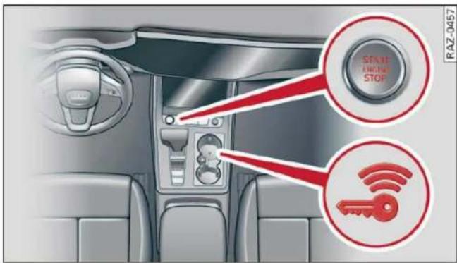
Fig. 85 Center console: starting the engine
Requirement: the key must be in the vehicle.
Starting the engine
▶ Press and hold the brake pedal.
▶ Press the START ENGINE STOP button. The engine will start.
Equipment that uses a lot of electricity is switched off temporarily when you start the engine. If the engine does not start immediately, the starting procedure stops automatically after a short time. If this is the case, repeat the starting procedure after approximately 30 seconds.
Stopping the engine
▶ Bring the vehicle to a full stop.
▶ Press the START ENGINE STOP button. The engine will switch off.
Applies to: vehicles with steering lock: The steering is locked when you turn off the engine with the selector lever in the "P" position and open the driver's door. The steering lock helps prevent vehicle theft.
Stopping the engine in an emergency
If necessary in an emergency, the engine can also be stopped while driving using the emergency off function*.
▶ Press the START ENGINE STOP button twice in a row or press and hold it one time.
Switching on and off
If you would like to switch the ignition on or off without starting the engine, follow these steps:
▶ Press the START ENGINE STOP button without pressing the brake pedal.
Switching the ignition off automatically
To prevent the vehicle battery from draining, the ignition and possibly the exterior lighting may switch off automatically.
Requirements:
- The Start/Stop system must have stopped the engine.
- You must have left the vehicle for longer than 30 seconds.
– The ignition must be switched on.
- The Start/Stop system must have stopped the engine. - You must have left the vehicle for longer than 30 seconds. - The ignition must be switched on.
Among other indicators, the system detects that you have left the vehicle based on the following factors:
– The driver's door has been opened.
– The driver's safety belt has been unbuckled.
– The brake pedal is not being pressed.
The ignition will also be switched off after 30 minutes or if you lock the vehicle from the outside.

WARNING
- To reduce the risk of asphyxiation, never allow the engine to run in confined spaces.
- Never turn off the engine before the vehicle has come to a complete stop. Switching it off before the vehicle has stopped may impair the function of the brake booster and power steering. You would then need to use more force to steer and brake the vehicle. The fact that you cannot steer and brake as usual may increase the risk of accidents and serious injuries.
- Always select the "P" selector lever position when parking the vehicle; otherwise, the vehicle could roll away.

Note
- Avoid high engine speed, full throttle, and heavy engine load if the engine has not
reached operating temperature yet. You could damage the engine.
- If the engine has been under heavy load for an extended period of time, heat builds up in the engine compartment after the engine is switched off and there is a risk of damaging the engine. For this reason, let the engine run at idle for approximately two minutes before shutting it off.
i Tips
– Brief noises are normal when starting and stopping the vehicle and are no cause for concern.
- For up to 10 minutes after stopping the engine, the radiator fan may turn on again automatically or it may continue to run, even if the ignition is switched off.
- It may not be possible to start the vehicle in extremely low temperatures.
– Power will be fully available once the engine is at operating temperature.
Messages
Engine start system: malfunction! Please contact Service
Do not switch the ignition off because you may not be able to switch it on again. Drive to an authorized Audi dealer or authorized Audi Service Facility immediately to have the malfunction corrected.
Engine start system: malfunction! Please contact Service
There is a malfunction in the engine start system. Drive immediately to an authorized Audi dealer or authorized Audi Service Facility to have the malfunction repaired.
Remote control key: key not detected. Is the key still in the vehicle?
The vehicle key was removed from the vehicle while the engine is running. If the vehicle key is no longer in the vehicle, you cannot switch the ignition on or start the engine once you stop it. You also cannot lock the vehicle from the outside.
Remote control key: hold back of key against the designated area. See owner's manual
The battery in the vehicle key may be drained or there may be a malfunction. To start the vehicle, you must also hold the vehicle key against the location shown page 92, fig. 85.
If the malfunction remains, drive immediately to an authorized Audi dealer or authorized Audi Service Facility to have the malfunction corrected.
When driving
Starting to drive, stopping, and parking
Starting from a stop
▶ Press and hold the brake pedal.
▶ Start the engine.
▶ Select a gear.
▶ Release the parking brake.
▶ Release the brake pedal. The vehicle may roll.
▶ Press the accelerator pedal to accelerate.
Stopping and parking
▶ Bring the vehicle to a full stop and press and hold the brake pedal.
▶ Set the parking brake.
▶ Select the "P" selector lever position to secure the vehicle from rolling away.
▶ Turn the steering wheel when parking on inclines so that the wheels will roll into the curb if the vehicle starts moving.
- Switch off the ignition before leaving the vehicle.
On hills, activate the parking brake first and then shift into the "P" selector lever position. This prevents too much stress from being placed on the locking mechanism.
! WARNING
- Always set the parking brake when leaving your vehicle, even if for a short period of time. If the parking brake is not set, the vehicle could roll away, increasing the risk of an accident.
- Do not leave your vehicle unattended while the engine is running, because this increases the risk of an accident.
- If the parking brake is set, it can release automatically when the accelerator pedal is pressed. To reduce the risk of an accident, do not inadvertently press the accelerator pedal and always shift into "P" when the vehicle is stopped.
- If you leave the vehicle, switch the ignition off and take the key with you. This is especially important when leaving persons or animals in the vehicle. Otherwise, the vehicle could start unintentionally, the parking brake could release, or electronic equipment could activate, which increases the risk of an accident.
- No persons or animals should be left in a locked vehicle. Locked doors make it more difficult for emergency workers to enter the vehicle, which puts lives at risk.
- If you do not begin driving immediately after releasing the brake pedal, your vehicle may begin to roll backward. Press the brake pedal or set the parking brake immediately.

Note
If you have to stop on an incline, always press the brake pedal to hold the vehicle in place to reduce the risk of the vehicle rolling backward. Do not try to hold the vehicle in place by pressing and holding the accelerator pedal. The transmission can overheat, which increases the risk of damage.
Hill hold assist
If you take your foot off of the brake pedal when driving on hills, the braking force will be held for several seconds. At that time, you can start driving without the vehicle rolling backward.
Requirement: the driver's door must be closed, the engine must be on, and the vehicle must be traveling uphill.
▶ To activate hill hold assist, press and hold the brake pedal for several seconds while the vehicle is stationary.

WARNING
- If you do not begin driving immediately after releasing the brake pedal, your vehicle may begin to roll backward. Press the brake pedal or set the parking brake immediately.
- The hill hold assist cannot hold the vehicle on inclines in every scenario (for example, on slippery or icy ground).
Gears and driving programs

Fig. 86 Center console: selector lever
The automatic transmission shifts automatically depending on the selected gear and the current driving style. When driving with a moderate driving style, upshifting early and downshifting late will help to improve fuel economy. When driving with a sporty driving style, the transmission permits higher RPMs.
The gears are displayed next to the selector lever.
- P (Park)
- R (Reverse)
- N (Neutral)
- D (Drive)
Selecting a gear
Requirement: the ignition must be switched on.
- Bring the vehicle to a full stop and press the brake pedal.
- Press the release button ① on the selector lever.
- To select the nearest gear, move the selector lever forward or back until you feel the first pressure point.
- To skip a gear (for example, move from "D" to "R"), move the selector lever past the pressure point in the desired direction.
- The label next to the selector lever for the selected gear will light up.
"N" (Neutral) gear
In the "N" gear, power is not transmitted to the driving wheels. Use the "N" gear in a car wash (with conveyor belts), for example.
If you unintentionally select "N" while driving (faster than 1 mph (2 km/h)), you can also shift back to "D" without pressing the brake pedal.
For safety reasons, the vehicle cannot be locked when the transmission is in the "N" gear.
"P" (Park) gear
Requirement: the ignition must be switched on.
The vehicle is secured from rolling away by the parking lock when in the "P" gear.
- Bring the vehicle to a full stop and press the brake pedal.
- Press the "P" button ② on the selector lever.
- The "P" next to the selector lever will light up.
"P" engages automatically if you switch the engine off while the "D" or "R" gear is selected. If you switch the engine off in "N", "P" will engage automatically after approximately 30 minutes.
If you want to switch to another gear from "P", the engine must be running.
If you cannot shift out of "P", for example because the vehicle has no power, you may need to use the emergency release for the parking lock page 97.
Selecting the driving program
Various driving programs can be selected when in the "D" gear. The programs influence when the transmission shifts and how the accelerator pedal responds.
The selected driving program is displayed in the instrument cluster.
- D (Drive): normal driving mode
- S (Sport): sporty driving mode
If you select the Dynamic mode in Audi drive select*, the "S" driving program will be activated. When the ignition is switched off, the driving program may be reset to "D".
To switch between the current driving program and "S", push the selector lever toward the rear.

WARNING
- Before starting to drive, check if the desired gear is displayed next to the selector lever.
- Always secure your vehicle from rolling away. Press the brake pedal or shift to "P". When leaving the vehicle, also set the parking brake.
- Power is still transmitted to the wheels when the engine is running at idle. To prevent the vehicle from "creeping", you must keep your foot on the brake in all selector lever positions (except "P" and "N") when the engine is running.
- To reduce the risk of an accident, do not press the accelerator pedal when changing gears if the vehicle is stationary and the engine is running.
- Never select the "R" or "P" gears while driving. Doing so could cause an accident.
- The vehicle can roll even if the ignition is switched off.

Tips
If you shift between "D" and "R" within one second, you do not need to press the brake pedal. This makes it possible to "rock" if it is stuck, for example.
Manual shifting

Fig. 87 Center console: shifting manually with the selector lever
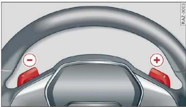
Fig. 88 Steering wheel: shift paddles*
You can shift the gears manually when in "D" mode. The transmission must be in tiptronic mode.
Shifting with the selector lever
You can shift into manual shifting mode while the vehicle is stationary or while driving.
▶ To switch to manual shifting mode, tilt the selector lever toward the front passenger's side fig. 87. "M" will be displayed in the instrument cluster.
▶ Upshifting: push the selector lever forward ⊕.
- Downshifting: push the selector lever toward the rear (-).
▶ To switch back to automatic mode, tilt the selector lever toward the driver's side.
Shifting with the shift paddles
Applies to: vehicles with shift paddles
▶ Upshifting: press the ⊕ shift paddle ⇒ fig. 88.
▶ Downshifting: press the ⏻ shift paddle.
▶ To engage the lowest possible gear for maximum acceleration, press and hold the ⏻ shift paddle.
▶ To switch back to automatic mode, press and hold the ⭕ shift paddle or push the selector lever toward the rear.
If you stop using the shift paddles temporarily, the transmission will switch back to automatic mode. To keep shifting manually, tilt the selector lever toward the front passenger's side.
i Tips
- The transmission only allows manual shifting when the engine speed is within the permitted range.
- The transmission automatically shifts up or down before critical engine speed is reached.
- Applies to: RS models: When accelerating, the transmission will not automatically shift to the next gear shortly before the maximum permitted engine RPM is reached. Shift to the next highest gear at the right time.
Accelerator pedal
You can accelerate the vehicle using the accelerator pedal.
Depending on the equipment, you may be able to adjust the haptic feedback for the accelerator pedal in the MMI.
- Select on the home screen: VEHICLE > (Charging & Efficiency) > Efficiency assist > (Interactive accelerator).
Accelerator pedal feedback / predictive messages
Haptic feedback in the accelerator pedal indicates when you should take your foot off the accelerator pedal to drive more efficiently.
Maximum acceleration
If you press the accelerator pedal all the way down, the motor's full power will be used and you will reach maximum acceleration, also called "kick-down".

WARNING
The driving wheels could spin and the vehicle could swerve on slick or slippery road surfaces when using kick-down, which increases the risk of an accident.
Launch Control
Applies to: RS models
Launch Control provides the best possible acceleration when starting from a stop.
Requirements
– The engine must be at operating temperature.
- The steering wheel must not be turned.
- Start/Stop system* must be deactivated
⇒ page 100.
- ESC must be limited page 113.
- Driving program "S" page 95 or the dynamic Audi drive select* mode must be selected page 108.
Using Launch Control
- Press the brake pedal with your left foot and hold it all the way down for at least one second.
- With the brake pedal pressed, press the accelerator pedal all the way down with your right foot at the same time.
- Once the engine reaches a constant speed, remove your foot from the brake pedal.
Once the vehicle has started moving, reactivate the ESC so that it is fully functional.

WARNING
Only use Launch Control when road and traffic conditions allow it and other road users will not be endangered or impacted by your driving and the vehicle's acceleration. The driving wheels could spin and the vehicle could swerve, especially on slick or slippery road surfaces, which increases the risk of an accident.

Note
When accelerating using Launch Control, all vehicle components are subject to heavy loads. This can result in increased wear.

Tips
After accelerating using the Launch Control, the temperature of some vehicle components may increase greatly. If that happens, the function will not be available for a few minutes to reduce the risk of damage. After a cool-down period, Launch Control will be available again.
Parking lock emergency release

Fig. 89 Footwell: releasing the parking lock using the emergency release
The emergency release is located under the floor mat on the driver's side. Read and follow the important instructions about towing page 285.
Releasing the parking lock using the emergency release
▶ To prevent your vehicle from rolling away, set the parking brake (P) ⇒ page 103.
▶ Pry the cover off at one of the openings using the screwdriver from the vehicle tool kit
⇒ page 276.
- Insert the socket wrench from the vehicle tool kit into the opening.
▶ Turn the socket wrench clockwise ① until it stops and press it downward ② until it locks into place.
▶ Leave the socket wrench inserted.
Resetting the parking lock
▶ Grasp the socket wrench with both hands and carefully pull it upward to remove.
▶ Install the cover.

WARNING
- The parking lock must be released using the emergency release before towing the vehicle.
- The parking lock may only be released using the emergency release if the parking brake is set. If it is not working, secure the vehicle from rolling using the brake pedal or other suitable means, such as blocking a front and a rear wheel. An unsecured vehicle may roll away, which increases the risk of an accident.
- Only activate the emergency release while on a level surface or a slight slope.
- To reduce the risk of an accident, you must not drive when the emergency release is activated.
Messages

Transmission: malfunction! Safely stop vehi-
Do not continue driving. Stop the vehicle as soon as possible in a safe location and secure it so it does not roll. See an authorized Audi dealer or authorized Audi Service Facility for assistance.

Transmission: too hot. Please stop vehicle
Do not continue driving. Select "P" and contact an authorized Audi dealer or authorized Audi Service Facility for assistance.

Transmission: too hot. Please adapt driving le
The transmission temperature has increased significantly. Drive very cautiously or take a break from driving until the temperature returns to the normal range and the indicator light turns off.

Transmission: malfunction! You can contin-driving. See owner's manual
There is a system malfunction in the transmission. You may continue driving. Drive to an authorized Audi dealer or authorized Audi Service Facility soon to have the malfunction corrected.

Transmission: malfunction! You can contin-driving with limited function. Please contact vice
There is a system malfunction in the transmission. The transmission is switching to emergency mode. This mode only shifts into certain gears or may no longer shift at all. The engine may stall. Drive to an authorized Audi dealer or authorized Audi Service Facility immediately to have the malfunction corrected.

Transmission: malfunction! You can contin- driving with limited function. No reverse
There is a system malfunction in the transmission. The transmission is switching to emergency mode. This mode only shifts into certain gears or may no longer shift at all. The engine may stall. You cannot engage the reverse gear. Drive to an authorized Audi dealer or authorized Audi Service Facility immediately to have the malfunction corrected.

Transmission: malfunction! You can contin-driving in D until engine is off
There is a system malfunction in the transmission. The transmission is switching to emergency mode. If you turn the engine off, you will not be able to select any other gears after restarting the engine. Drive to an authorized Audi dealer or authorized Audi Service Facility immediately to have the malfunction corrected.

Selector lever: malfunction! You can contin-driving. Please contact Service
There is a system malfunction in the selector lever. Drive immediately to an authorized Audi dealer or authorized Audi Service Facility to have the malfunction repaired.

Selector lever: malfunction! Gear change on- possible if using both shift paddles.
There is a system malfunction in the selector lever. You can continue driving with restricted function. The selector lever is not working. Gears can only be selected by tapping both shift paddles at the same time when the vehicle is stationary. The "P" gear is automatically engaged when you turn
off the engine. Drive to an authorized Audi dealer or authorized Audi Service Facility immediately to have the malfunction corrected.
P button: malfunction! Auto P when engine off. Please contact Service
There is a malfunction in the "P" button on the selector lever. The "P" gear is automatically engaged when you turn off the engine. Drive to an authorized Audi dealer or authorized Audi Service Facility immediately to have the malfunction corrected.
Danger of rolling away! P not possible. Please apply parking brake
The parking lock was released using the emergency release page 97 or can no longer be engaged. Drive to an authorized Audi dealer or authorized Audi Service Facility immediately to have the malfunction corrected.
Move selector lever to automatic position
The transmission has switched out of tiptronic mode. Switch back to automatic mode with the selector lever page 96.
Drive system
Breaking in
A new vehicle must be broken in within the first 1,000 miles (1,500 km) so that all moving parts work smoothly together, which helps to increase the service life of the engine and other drive components.
Do not drive higher than two-thirds of the maximum permitted engine RPM during the first 600 miles (1,000 km) and do not use full acceleration. The engine can be increased RPM gradually during the next 300 miles (500 km).
Conventional and mild hybrid drive system
Applies to: vehicles with a conventional drive system or a mild hybrid drive system
Vehicles with a conventional or mild hybrid drive system are powered by a combustion engine. It uses fuel to recover energy.
Vehicles with a mild hybrid drive system have additional battery technology.
Efficient and environmentally-friendly driving
Your driving style greatly influences the amount of fuel and energy consumed, the environmental impact, and the wear on the engine, brakes, and tires. Note the following information for efficient and environmentally-conscious driving:
- Turn off electrical equipment that is not needed, for example seat heating*.
– Anticipate upcoming traffic situations while driving to avoid unnecessary acceleration and braking.
– Avoid driving at high speeds.
- Avoid adding extra weight to the vehicle if possible, for example by not leaving roof racks or bike racks installed when they are not needed.
- Make sure the tire pressure is correct.
– Have maintenance performed regularly on the vehicle.
- Do not drive with winter tires during the summer.
- Do not let the engine run while the vehicle parked.
- Use the Start/Stop system.
- Utilize the engine braking effect.
– Avoid driving short distances when possible.
i Tips
The amount of noise produced by the vehicle can increase significantly when driving with a sporty style. Show respect to others around you and the environment with the way you operate your vehicle, especially at night.
Energy management
Your vehicle is equipped with an intelligent energy management system for distributing electricity. This significantly improves the starting ability and increases the vehicle battery life.
i Tips
- If you drive short distances frequently, the vehicle battery may not charge enough
while driving. As a result, convenience functions for electrical equipment may be temporarily unavailable.
- The vehicle battery will gradually drain if the vehicle is not driven for long periods of time, or if electrical equipment is used when the engine is not running. To ensure that the vehicle can still be started, the electrical equipment will be limited or switched off.
Messages
Drive system: malfunction! Safely stop vehicle
There is a malfunction in the drive system. The brake booster and the power steering may stop working. Stop the vehicle immediately or as soon as possible and do not continue driving. Have the problem corrected by an authorized Audi dealer or authorized Audi Service Facility.
Drive system: malfunction! Please contact Service
There is a malfunction in the drive system. Drive slowly to an authorized Audi dealer or authorized Audi Service Facility to have the malfunction corrected.
Start/Stop system
Description
Applies to: vehicles with Start/Stop system
The Start/Stop system can help increase fuel economy and reduce CO2 emissions.
In Start/Stop mode, the engine shuts off automatically when stopped, for example at a traffic light. The ignition and important assist systems such as power steering and the brake booster will remain available during the Stop phase. The engine will restart automatically when needed.
The Start/Stop system is automatically activated once the ignition is switched on.
Switching the Start/Stop system off and on
The Ⓐ OFF button is located above the selector lever in the center console. The LED in the button turns on when the function is switched off.
▶ Press Ⓐ to switch on or off.
If you switch the system off during a Stop phase, the engine will start again automatically.
Basic requirements
– The driver's door and hood must be closed.
- "P", "N", or "D" must be engaged.
- The steering wheel must not be turned far in either direction.
- The vehicle must have driven faster than 2 mph (3 km/h) since the last time it stopped.
– The vehicle is not in trailer mode.
Note
Always switch the Start/Stop system off when driving through water page 100.
i Tips
- Depending on the driving situation, the engine may already stop when coasting before the vehicle has come to a complete stop.
- If you select the "D" position after shifting into reverse, the vehicle must be driven faster than 6 mph (10 km/h) in order for the Start/Stop system to become active again. This makes it possible to maneuver without stopping the engine.
Stopping and starting the engine
Applies to: vehicles with Start/Stop system
▶ Press and hold the brake pedal until the vehicle has stopped. The Ⓐ indicator light appears in the instrument cluster once the engine stops automatically.
▶ The engine starts again when you remove your foot from the brake pedal. The indicator light turns off.
If the parking brake is set, the engine will only start again when the accelerator pedal is pressed.

Tips
- Press the brake pedal during a Stop phase to keep the vehicle from rolling.
- The ignition will turn off if you press the START ENGINE STOP button during a Stop phase.
- If you leave the vehicle briefly during a Stop phase, the driver's door must be closed and the safety belt buckled for the engine to be able to restart.
- You can control if the engine will stop or not by reducing or increasing the amount of force you use to press the brake pedal. For example, if you only lightly press on the brake pedal in stop-and-go traffic or when turning, the engine will not switch off when the vehicle is stationary. If you press the brake pedal harder, the engine will switch off.
Starting and stopping the engine automatically
Applies to: vehicles with Start/Stop system
The system checks if certain conditions are met before and during the Stop phase, and determines if the engine stops and how long it remains stopped. For example, if power usage is high, the engine will not be stopped. Along with other conditions, the following factors influence the automatic engine start or stop:
- Environmental conditions (slopes, inclines, elevation, temperature)
- Battery (charge status, temperature, power usage)
- Engine temperature
- Assist systems
- Driving behavior
Messages
Applies to: vehicles with Start/Stop system
Drive system: please start the vehicle manually
This message appears when specific conditions are not met during a Stop phase. The Start/Stop system will not be able to restart the engine. The engine must be started with the START ENGINE STOP button.
Vehicle starting system: malfunction! Please contact Service
There is a malfunction in the Start/Stop system. Drive the vehicle to an authorized Audi dealer or authorized Service Facility as soon as possible to have the malfunction corrected.
Brakes
General information
You can apply the vehicle's brakes using the brake pedal.
Operating noise
Noises may occur when braking depending on the speed, braking force, and outside conditions such as temperature and humidity.
Braking effect
The response time from the brakes depends on the weather and environmental conditions. To ensure the optimal braking effect, the brake system is cleaned at regular intervals. This is done by applying the brake pads to the brake rotors for a short period of time when driving at high speeds when the windshield wipers are switched on.
If the brake system becomes damp, for example after driving in heavy rain, the braking effect may be delayed. Other factors that could temporarily increase the response time of the brakes include:
– Wet conditions
– Low temperatures, ice, and snow
– Roads covered in salt
– Dirty brake pads
Corrosion
Corrosion may form on the brake rotors if there is no heavy braking, if the vehicle is not driven for long periods of time, or if the vehicle is not driven frequently or for long distances. In this case, braking heavily several times while driving at high speeds can clean the brake rotors △.
Brake pads
New brake pads do not achieve their full braking effect during the first 250 miles (400 km). They must be “broken in” first. However, you can compensate for the slightly reduced braking force by pressing firmly on the brake pedal. Avoid heavy braking during the break-in period.
Brake pad wear depends largely on the way the vehicle is driven and on operating conditions. Brake pad wear increases when driving frequently in the city or short distances or when using a very sporty driving style.
Ceramic brakes
Applies to: vehicles with ceramic brakes
Ceramic brakes provide excellent deceleration rates.
The break-in period for new ceramic brakes may be significantly longer than for standard brake rotors. Due to the properties of the material, they may cause noises at lower speeds. Ceramic brakes also absorb more moisture in wet conditions. Therefore, there will temporarily be less braking force than when the brakes are dry. You can compensate for this by pressing the brake pedal harder.

WARNING
- Only apply the brakes for the purpose of cleaning the brake system when road and traffic conditions permit. You must not endanger other road users and increase the risk of an accident.
– Due to the risk of injury, only have an authorized Audi dealer or authorized Audi Service Facility work on the brake system. Incorrect repairs could impair the function. - Never let the vehicle roll while the engine is stopped because this increases the risk of an accident.
– During automatic braking maneuvers, the brake pedal may move downward automatically. To reduce the risk of injury, do not place your foot under the brake pedal.

Note
- Never let the brakes "rub" by pressing the pedal lightly when braking is not actually necessary. This can cause the brakes to overheat and increases braking distance and causes wear.
- Observe the important information for driving downhill page 105. This especially applies when towing a trailer.

Tips
- If you retrofit your vehicle with a front spoiler, wheel covers or similar items, make sure that the air flow to the brakes is not obstructed. Otherwise the brake system can overheat.
- Also refer to the information about brake fluid page 242.
Messages


Brakes: malfunction! Safely stop ve-
There is a malfunction in the brake system. If ABS / and also turn on, there is a malfunction in the ABS, ESC, and braking distribution.
Do not continue driving. See an authorized Audi dealer or authorized Audi Service Facility for assistance. Read and follow the other safety precautions .


Brake pads: wear limit reached. You use driving. Please contact Service
The brake pads are worn. Drive to an authorized Audi dealer or authorized Audi Service Facility as soon as possible to have the malfunction corrected.
Brake booster: limited functionality. You can continue driving. Please contact Service
There is a brake booster malfunction. The brake booster is available, but its effectiveness is reduced. The braking performance may be different compared to the usual performance. Drive to an authorized Audi dealer or authorized Audi Service Facility immediately to have the malfunction corrected.
Brake booster: deactivated. See owner's manual
The brake booster remains active for a brief period of time after switching off the ignition. Secure the vehicle from rolling by setting the parking brake and select the "P" gear.
Other indicator lights
When you switch the ignition on, the indicator light BRAKE / ⏻ turns on briefly to check the function. If the indicator light does not turn on, there is a system malfunction.
If BRAKE / Ⓞ stays on, there is a malfunction in the brake system.
(1) - A high load was placed on the brakes from driving downhill for a long period of time. Follow the instructions in the message to utilize the engine braking effect and to relieve the brakes.

WARNING
If a malfunction occurs in the ABS, ESC, and braking distribution, interventions that stabilize the vehicle will no longer be available. This could cause the vehicle to swerve, which increases the risk that the vehicle will slide. Do not continue driving. See an authorized Audi dealer or authorized Audi Service Facility for assistance.
Electromechanical parking brake
Operating the parking brake
The electromechanical parking brake is used to secure the vehicle from rolling away unintentionally.
The Ⓓ switch is located under the selector lever in the center console. It turns on when the parking brake is set. You can release the parking brake manually or automatically when you start to drive.
Setting and releasing the parking brake
▶ Setting: pull the Ⓓ switch.
▶ If PARK / 📋 appears, the parking brake is holding the vehicle. You can remove your foot from the brake pedal.
▶ Releasing: when the ignition is switched on, press and hold the brake pedal and press the (P) button.
If the red indicator light flashes, the braking force has not built up enough or it has decreased. You can also secure the vehicle by selecting the "P" gear or pressing the brake pedal. Make sure the indicator light is off before you start driving.
Automatically releasing the parking brake when starting to drive
Requirement: the driver's door must be closed and the driver's safety belt must be fastened.
▶ Press the accelerator pedal to start to drive.

WARNING
- To reduce the risk of an accident, always make sure the vehicle is situated safely while stationary.
- If the parking brake is set, it can release automatically when the accelerator pedal is pressed. To reduce the risk of an accident, do not inadvertently press the accelerator pedal and always shift into "P" when the vehicle is stopped.
- If the power supply fails, you cannot set the parking brake once it is released, or release it if it is set. In this case, park the vehicle on level ground and secure it by engaging the "P" gear. Contact an authorized Audi dealer or authorized Audi Service Facility for assistance.

Tips
- On steep inclines, especially when in trailer mode, the vehicle may roll backwards unintentionally when starting to drive. To reduces the risk of this happening, pull and hold the Ⓓ switch while pressing the accelerator pedal. If enough drive power has built up at the wheels and the vehicle does not roll backwards, then release the switch to start to drive.
- If you leave the vehicle when "D" or "R" are engaged, the parking brake will be set automatically.
- Noises when the parking brake is set and released are normal and are not a cause for concern.
- The parking brake goes through a self-test cycle at regular intervals when the vehicle is stopped. Any noises associated with this are normal.
Emergency braking function
Emergency braking should only be used in an emergency, if the standard brake pedal is malfunctioning or obstructed. When the emergency braking function is activated, the braking effect is similar to a heavy braking maneuver.
▶ Pull and hold the Ⓟ switch while driving.
▶ An audio warning signal will sound and emergency braking will begin.
▶ If you press the accelerator pedal, emergency braking will be canceled.

WARNING
Heavy braking while driving through curves or in poor road or weather conditions can cause the vehicle to slide or the rear of the vehicle to swerve, which increases the risk of an accident.
Messages
BRAKE / Parking brake: malfunction! Safely stop vehicle. See owner's manual
There is a malfunction in the parking brake. If the message appears while stationary, check if the parking brake is released and can be reset. If this is the case, switch the ignition off and back on.
If the message continues to appear, if the parking brake cannot be released, or if the message appears while driving, then stop the vehicle on level ground and shift to "P". Do not continue driving. See an authorized Audi dealer or authorized Audi Service Facility for assistance.
BRAKE / Ⓑ Parking brake: malfunction! Please release parking brake
There is a malfunction in the parking brake. If the message appears while stationary, check if the
parking brake is released and can be reset. If this is the case, switch the ignition off and back on.
If the message continues to appear, if the parking brake cannot be released, or if the message appears while driving, then stop the vehicle on level ground and shift to "P". Do not continue driving. See an authorized Audi dealer or authorized Audi Service Facility for assistance.
Parking brake: malfunction! Please contact Service
There is a malfunction in the parking brake. Drive to an authorized Audi dealer or authorized Audi Service Facility immediately to have the malfunction corrected. Do not park the vehicle on inclines and shift to "P".
PARK BRAKE / (P) Parking brake: warning! Vehicle parked too steep
The braking force may not be enough to secure the vehicle from rolling away. Park the vehicle in a place with less of an incline.
PARK/ Parking brake: applied
The parking brake is set. Press and hold the brake pedal to release the parking brake.
Special driving situations
Sporty driving
Applies to: RS models
When driving in a sporty style, for example on a driving track, the wear on all vehicle components is greatly increased, especially on the engine, transmission, tires, brakes, and suspension. This can result in increased wear. Also note the following points:
- Make sure the vehicle is in good condition. Make sure to check the brake pads, tire tread, and tire pressure (when tires are warm).
- Beforehand, warm up the engine by driving no higher than two-thirds of the maximum permitted engine RPM. The engine oil must be brought to a minimum temperature of 158 °F (70 °C).
– Before stopping the vehicle, allow the engine and brakes to cool back down to a regular operating temperature by driving normally.
If necessary, use the following functions:
– Audi drive select* dynamic mode ⇒ page 108
- Limit ESC page 114

Tips
Wear caused by load does not constitute a vehicle fault as defined by the terms of the warranty.
Driving uphill and downhill
When driving uphill, downhill, or at high altitudes, note the following information:
- Drive slowly and carefully.
- Do not try to turn around if you cannot safely drive on an incline or hill. Instead, drive in reverse.
- When driving down hills, you can activate the hill descent control if you press the brake pedal while driving in "D" gear. The automatic transmission will select a gear suitable for driving down the hill and will attempt to maintain the speed at which the vehicle was traveling at the time the brake pedal was pressed. Press the brake pedal if necessary. The hill descent control will switch off once the hill levels out or you press the accelerator pedal.
- Utilize the engine braking effect when driving downhill by selecting the "S" driving program page 95. This especially applies when towing a trailer. This reduces the load on the brakes.
- Brake in intervals and do not press the brake pedal continuously.
- Use the hill descent assist if necessary ⇒ page 106
Inclinometer
Applies to: vehicles with a tilt angle display
You can display the vehicle's sideways angle and lengthwise angle in relation to the horizon.
- Applies to: MMI: Select on the home screen: VEHICLE > Vehicle data.
- You may need to scroll down to the Inclinometer display.
The sideways angle of your vehicle should not exceed the yellow range in the gauge. If it reaches the red range, there is a risk that the vehicle might tip.
The steering wheel angle, the elevation, the compass direction, and the geo-coordinates of the current vehicle position are displayed in addition to the current vehicle angle. You will also receive information about the maximum sideways and lengthwise angle that was reached in the current driving cycle. These values are reset when the ignition is switched off.
Note that the accuracy of the display depends on the driving situation.

WARNING
- Only drive on inclines that your vehicle is designed to handle. Do not exceed the hill climbing ability of your vehicle. Your vehicle could tip or slide.
- Do not drive at an angle on steep inclines and hills. If your vehicle is about to tip, you must immediately start steering in the direction of the downward slope to reduce the risk of an accident.
- Always be ready to brake when using the hill descent control function.
- Applies to: vehicles with an inclinometer: Do not rely only on the inclinometer when assessing the driving situation.
Offroad driving
Your vehicle is not an offroad vehicle. Note the following points when driving offroad:
- Drive slowly and carefully.
- To reduce the risk of underbody damage, pay attention to the vehicle's ground clearance and drive across raised areas of the ground with the wheels on one side of the vehicle, instead of allowing the center of the vehicle to pass over the raised areas.
- To reduce the risk of becoming stuck, drive through sandy or swampy areas at a steady speed and without stopping, if possible.
If necessary, use the following functions:
– Audi drive select* dynamic mode ⇒ page 108
– Hill descent assist* → page 106
- Inclinometer* page 105
– Raising the vehicle page 109
- Limit ESC page 114

WARNING
Only drive in terrain that is suitable for the vehicle and your driving ability.

For the sake of the environment
Avoid actions that are damaging to the environment. Show respect for the natural environment and remain on marked routes.

Tips
Clean your vehicle after driving offroad. Dirt and stones falling off your vehicle can affect other road users.
Driving through water
If you must drive through water, follow these instructions:
- Check the stability of the ground, the current, and the water depth. If the ground is unstable, there is a strong current, or there are waves, the water must only reach up to the lower edge of the body at the most.
– Deactivate the Start/Stop system.
- Drive carefully and no faster than at walking speeds to prevent the front of the vehicle from creating waves, because they could splash above the lower edge of the body. Oncoming vehicles could also create waves.
- Do not stop the vehicle while in the water.
- Drive in reverse.
- Do not turn the engine off.

WARNING
After driving through water, press the brake pedal carefully to dry the brakes so that the full braking effect will be restored.

Note
Vehicle components such as the engine, drive system, suspension, or electrical system, can be severely damaged by driving through water.

Tips
If possible, avoid driving through salt water because it increases the risk of corrosion. Use fresh water to clean any vehicle components that come into contact with salt water.
Hill descent assist
Applies to: vehicles with hill hold assist
The 🎨 button is located in the function bar on the lower display. It lights up when the system is turned on.
Hill descent assist can assist you when driving down hills by maintaining a constant vehicle speed by automatically braking all four wheels. You can adjust the speed using the accelerator and brake pedals. The regulation depends on the hill and the vehicle speed.
▶ Switching on: press 📄.
▶ Switching off: press 📄 again.
Active regulation
Regulation begins shortly after you start driving and is possible at speeds up to approximately 19 mph (30 km/h) and on hills that have an approximately 6-60% grade. If these conditions are met, regulation will be activated and the indicator light will turn on.
Ready mode
If one of the requirements for active regulation is not met, the system will be in ready mode. The indicator light will turn on. Once the requirements are met again, the system will be able to provide active regulation again.

WARNING
- Be ready to apply the brakes at all times when using the hill hold assist.
- Always adjust the speed to the visibility, weather, road, and traffic conditions. The system cannot replace the driver's attention.
- The system cannot maintain a constant vehicle speed in all situations, for example when on smooth or slippery ground. This can increase the risk of an accident.

Tips
If you select the Audi drive select* offroad mode, hill descent assist will switch on.
Driving dynamic
Audi drive select
Introduction
Applies to: vehicles with Audi drive select
Drive select makes it possible to experience different types of vehicle characteristics in one vehicle. With different driving modes, the driver can switch the setting, for example from sporty to comfortable. This allows you to adjust the settings to your personal preferences. This makes it possible to combine settings such as a sporty drivetrain setting with comfortable steering.
Selecting an Audi drive select mode
Applies to: vehicles with Audi drive select
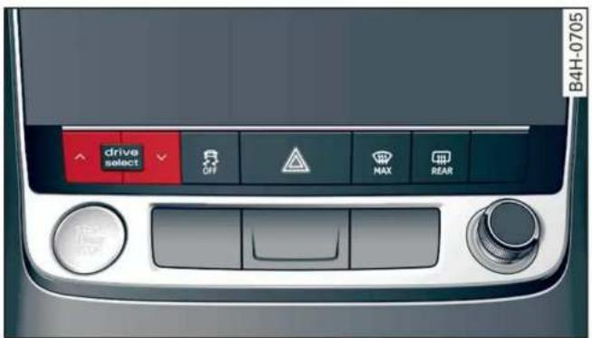
Fig. 90 Center console: Audi drive select button
▶ Press the left or right arrow key fig. 90 until the desired mode appears in the MMI. Or:
▶ Applies to: MMI: Select on the home screen:
VEHICLE > Audi drive select.
You can change the driving mode when the vehicle is stationary or while driving. If traffic permits, briefly remove your foot from the accelerator pedal after changing modes so that the mode you have selected will be activated for the drive system.
The following modes are available depending on the equipment:
offroad – Provides assistance when driving off-road. The vehicle will be raised to the second-highest level using the air suspension*. The ESC will be restricted and the hill descent assist* will be activated. The vehicle will exit this mode after the ignition is switched off.
allroad – Provides balanced vehicle handling. The vehicle will be raised to the second-highest level using the air suspension*.
comfort - Provides a comfort-oriented vehicle setup and is suited for long drives on highways.
auto - Provides an overall comfortable yet dynamic driving feel and is suited for everyday use.
dynamic - Gives the driver a sporty driving feel and is suited to a sporty driving style. The "S" driving program is selected.
individual – Provides the option for personalized vehicle settings. Press ☑ to configure the mode → page 108, Individual settings.
i Tips
When the ignition is being switched on, individual systems, such as the drive system, will be reset to a balanced setting. Select the current mode again to attain its full configuration.
Selecting RS mode
Applies to: RS models
In RS models, there are two individual adjustable RS modes instead of the individual mode.
Selecting the mode
▶ Press the RS MODE button on the multi-function steering wheel to switch between the RS modes and the last selected Audi drive select mode. Or:
▶ Applies to: MMI: Select on the home screen: VEHICLE > Audi drive select.
Adjusting the mode
Applies to: MMI: Select on the home screen: VEHICLE > Audi drive select.
▶ Press ☑ to configure the RS mode page 108, Individual settings.
Individual settings
Applies to: vehicles with Audi drive select
The equipment in your vehicle will determine which settings you can adjust.
Drive
The drive system will react to accelerator pedal moves more quickly or in a more balanced manner. The shift points are placed in higher or lower speed ranges.
Depending on the setting, the drive power at the rear axle will be distributed with the sport differential* to be more sporty or moderate ⇒ page 112.
In RS models, the sport differential is adjusted using a separate menu item.
Steering
The power steering will adapt. Light steering is suitable for long trips on highways or smooth driving around curves, for example.
Suspension
The suspension adjusts to be tighter or more comfort-oriented when it comes to compensating for uneven spots on the road.
Based on the selected setting, the air suspension* will adjust the ground clearance and the active roll stabilization* will provide various degrees of compensation for vehicle movements.
Engine sound
The engine sound adapts and can be subtle to sporty.
quattro with sport differential
Applies to: RS models
Depending on the setting, the drive power at the rear axle will be distributed with the sport differential* to be more sporty or moderate ⇒ page 112.
ESC
Applies to: RS models
The ESC sport mode can be activated. Also refer to the important information regarding driving with limited ESC page 114.
Suspension
Adaptive dampers
Applies to: vehicles with suspension control
The adaptive dampers are an electronically-controlled damping system. The firmness of the suspension will adapt to the driving conditions and the driving situation. The settings depend on the selected Audi drive select* mode.
Air suspension
Applies to: vehicles with air suspension
The air suspension is an electronically-controlled suspension and leveling system. The firmness of the suspension will adapt to the driving conditions and the driving situation. The system balances out changes in load. The vehicle level will also adapt gradually to the vehicle speed in order to reduce the wind resistance at high speeds and increase the ground clearance at low speeds. The settings depend on the selected Audi drive select* mode.
Displaying the vehicle level
▶ Applies to: MMI: Select on the home screen: VEHICLE > Audi drive select.
The filled-in boxes represent the current vehicle level. The more boxes that are filled in, the higher the ground clearance. The box that corresponds with the current vehicle level will flash while the vehicle is lifting or lowering. The target level is indicated by a red outline.
Raising the vehicle
▶ Applies to: MMI: Select on the home screen: VEHICLE > Audi drive select.
▶ Press Raise to reach the highest vehicle level and thus the maximum ground clearance.
▶ Press Lower to lower the vehicle down again.
The Audi drive select* mode will be changed if necessary when the vehicle is raised.
The vehicle will lower at speeds of approximately 20 mph (30 km/h) and below. This function may only be used temporarily when increased ground clearance is necessary. It is not intended for long drives.

Note
- Also refer to the information about ground clearance page 110.
- When transporting the vehicle on a road carrier, rail carrier, ship carrier, or other carrier, it may only be secured at the running surfaces of the tires (circumference). Securing the vehicle at the axle components, suspension struts, or towing eyes is not permitted because the pressure in the air suspension struts can change during transport. The vehicle might not be secured sufficiently if this happens.
Active roll stabilization
Applies to: vehicles with active roll stabilization
The active roll stabilization enhances the air suspension with an electromechanically-controlled suspension system. It influences targeted rolling movements when driving on curves and during fast swerving maneuvers. The settings are dependent on the selected Audi drive select* mode.
Ground clearance
The vehicle height and clearance can be influenced by the following factors:
- Change in temperature
- Change in load
- Change to the Audi drive select* mode
– Lifting and lowering via the air suspension*
– Lower the rear* of the vehicle

WARNING
To reduce the risk of injury, make sure no one gets pinched when the vehicle level is changing, for example when cleaning the underbody or the wheel housings.

Note
Always make sure there is enough clearance above and below the vehicle. This is especially important for entrances with height restrictions, for example, before driving into underground garages. You could also scrape the ground when driving over the edges of curbs
or on steep ramps, which could damage your vehicle.
Messages
Air suspension: malfunction! You may continue driving slowly at max. XX mph (km/h)
There is a malfunction. Driving stability may be limited. Drive to an authorized Audi dealer or authorized Audi Service Facility immediately. Do not drive faster than the speed given in the message.
Air suspension: malfunction! You can continue driving. Speed limited to max. XX mph (km/h)
There is a malfunction. Driving stability may be limited. Drive to an authorized Audi dealer or authorized Audi Service Facility immediately. The maximum speed has been limited.
Air suspension: malfunction! Safely stop vehicle. Steering and ground clearance limited
There is a malfunction. Do not continue driving. Stop the vehicle safely. Avoid turning the steering wheel, because the vehicle ground clearance may be so low that turning the steering wheel could result in damage to the wheels and wheel housings.
Active roll stabilization: malfunction! Limited stability. See owner's manual
There is a heavy load on the vehicle electrical system or the roll stabilization. The roll stabilization functions have already been switched off temporarily. Driving stability is reduced. Continue driving with caution.
If the indicator light does not turn off after a long period time and after switching the ignition off and on, drive to an authorized Audi dealer or authorized Audi Service Facility immediately to have the malfunction corrected. Otherwise, conditions such as an uneven road surface can lead to vehicle damage.
Suspension: malfunction! You can continue driving
There is a malfunction. See an authorized Audi dealer or authorized Audi Service Facility for assistance.
Air suspension: vehicle too low. Limited ground clearance
The vehicle ground clearance is very low. Wait until the air suspension system has restored normal ground clearance. Have an authorized Audi dealer or authorized Audi Service Facility repair the malfunction immediately if the indicator light does not turn off after a significant period of time.
Air suspension: malfunction! Please contact Service
There is a malfunction. The driving stability may be limited and the ground clearance may be low. See an authorized Audi dealer or authorized Audi Service Facility for assistance.
Audi drive select: automatic suspension lowering. See owner's manual
The vehicle level is adjusted to the setting stored for the active personal profile page 29.
Audi drive select: automatic suspension lift. See owner's manual
The vehicle level is adjusted to the setting stored for the active personal profile page 29.
Steering
Description
Electromechanical steering supports the driver's steering movements by electronically adapting the power steering depending on the vehicle speed. The settings depend on the selected Audi drive select* mode.
Progressive steering
Applies to: vehicles with progressive steering
The driving dynamic and driving stability are increased by the steering ratio based on the steering wheel angle. The steering is very direct when the steering wheel angle is sharp, and indirect when the angle is low. This enables comfortable maneuvering and a precise steering response at higher driving speeds.
All-wheel steering
Applies to: vehicles with all-wheel steering
Additional steering ability at the rear axle improves the driving dynamic and stability. At low speeds, the rear wheels are steered in the opposite direction from the front wheels to reduce the turning radius. At high speeds, steering the rear wheels in the same direction as the front wheels improves the vehicle response and driving stability.
Messages
Steering: malfunction! Please stop vehicle
The power steering may have failed. Adapt your driving style immediately to compensate for the fact that it may be more difficult to turn the steering wheel, and stop your vehicle in a safe location as soon as possible. Do not continue driving. See an authorized Audi dealer or authorized Audi Service Facility for assistance.
Steering: malfunction! Please stop vehicle. Pay attention to distance at side
The rear axle steering may have failed. More space on the road may be needed at the side of the vehicle, and the turning radius may be much larger. Slow down immediately, and stop your vehicle as soon as possible in a safe location with enough space at the sides of the vehicle. Do not continue driving. See an authorized Audi dealer or authorized Audi Service Facility for assistance.
Steering: malfunction! Please stop vehicle
There is a malfunction in the electronic steering lock. You cannot turn the ignition on. Do not tow your vehicle because it cannot be steered. See an authorized Audi dealer or authorized Audi Service Facility for assistance.
@! Steering: malfunction! You can continue driving
There is a malfunction in the steering system. Steering may be more difficult or more sensitive. Adapt your driving style. Have the steering system checked immediately by an authorized Audi dealer or authorized Audi Service Facility. Please note that the red indicator light may turn on
after restarting the engine. Do not continue driving if it does.
Steering: malfunction! Adapt driving style. Larger turning radius
The rear axle steering may have failed. The vehicle will have a larger turning radius, and the stability when driving around curves will be comparable to a vehicle without rear axle steering. Drive carefully to an authorized Audi dealer or authorized Audi Service Facility to have the malfunction corrected.
Steering lock: malfunction! Please contact Service
There is a malfunction in the electronic steering lock. Drive immediately to an authorized Audi dealer or authorized Audi Service Facility to have the malfunction repaired.

WARNING
Do not tow your vehicle if there is a malfunction in the electronic steering lock because this increases the risk of an accident.

Tips
- If there is a malfunction, the steering wheel may be crooked when driving straight.
- If the 📄! or 📄! indicator light only stays on for a short time, you may continue driving.
Applies to: vehicles with all wheel drive
The all-wheel drive system distributes the driving power variably to the front and rear axle to improve the driving characteristics. It works together with selective wheel torque control, which can activate when driving through curves ⇒ page 113.
The all-wheel drive system is designed for high engine power. Your vehicle is exceptionally powerful and has excellent driving characteristics both under normal driving conditions and on snow and ice. Always read and follow safety precautions ▲.

WARNING
- Even in vehicles with all wheel drive, you should adapt your driving style to the current road and traffic conditions to reduce the risk of an accident.
- The braking ability of your vehicle is limited to the traction of the wheels. In this way, it is not different from a two wheel drive vehicle. Do not drive too fast because this increases the risk of an accident.
- Note that on wet streets, the front wheels can "hydroplane" if driving at speeds that are too high. Unlike front wheel drive vehicles, the engine RPM does not increase suddenly when the vehicle begins hydroplaning. Adapt your speed to the road conditions to reduce the risk of an accident.
Sport differential
Applies to: vehicles with sport differential
The sport differential distributes the drive power to the rear axle based on the situation. The goal is a high level of agility and ability to accelerate on curves. The vehicle is very responsive to steering. The settings depend on the selected Audi drive select* mode.
Messages
Sport differential: malfunction! Please contact Service
Drive immediately to an authorized Audi dealer or authorized Audi Service Facility to have the malfunction repaired.
Sport differential: temperature too high. Please adapt driving style
The transmission temperature has increased significantly due to the sporty driving manner. Drive in a less sporty manner until the temperature returns to the normal range and the indicator light switches of.

WARNING
Contact an authorized Audi dealer or authorized Audi Service Facility if the sport
differential is faulty or malfunctioning. The repair must be performed by trained personnel using the correct oil in order to ensure safety.
Electronic Stabilization Control
Description
Electronic Stabilization Control (ESC) supports driver safety. It reduces the risk of slipping and improves driving stability. ESC detects critical situations, such oversteering and understeering of the vehicle, the drive wheels spinning, or the risk of the vehicle tipping. The brakes are applied or the engine torque is reduced in order to stabilize the vehicle.
If the 📄 indicator light blinks while driving, the ESC is actively regulating.
If the 📄 indicator light turns on, the system has switched the ESC off. In this case, you can switch the ignition off and then on to switch the ESC on again. The indicator light turns off when the system is fully functional.
If the 📄 indicator light turns on, ESC was limited or switched off manually ⇒ page 114.
The following systems are integrated in the ESC:
Anti-lock braking system (ABS)
ABS prevents the wheels from locking when braking. The vehicle can still be steered even during hard braking. Apply steady pressure to the brake pedal. Do not pump the pedal.
A pulsing in the brake pedal indicates that the system is acting to stabilize the vehicle.
Brake assist
The brake assist system can decrease braking distance. It increases braking power when the driver presses the brake pedal quickly in emergency situations. You must press and hold the brake pedal until the dangerous situation is over. Depending on the activated driver assistance systems, the brake assist system may react with increased sensitivity.
Anti-Slip Regulation (ASR)
ASR reduces drive power when the wheels begin spinning and adapts the power to the road conditions. This will increase the driving stability.
Electronic Differential Lock (EDL)
The EDL applies the brakes to wheels that are slipping and transfers the drive power to the other wheels. This function is not available at higher speeds.
In extreme cases, EDL automatically switches off to keep the brake on the braked wheel from overheating. The vehicle is still functioning correctly. EDL will switch on again automatically when conditions have returned to normal.
Power steering
The ESC can also support vehicle stability through steering.
Selective wheel torque control
Selective wheel torque control is used when driving on curves. Braking is targeted toward the wheels on the inside of the curve as needed. This allows more precise driving in curves.
Automatic post-collision braking system
The automatic post-collision braking system can help to reduce the risk of sliding and of additional collisions after an accident. If the airbag control module detects a collision, the vehicle is braked by the ESC.
The vehicle does not brake automatically if one of the following occurs:
– The driver presses the accelerator pedal, or
– The braking force generated by the pressed brake pedal is greater than the braking force that would be initiated by the system
– The ESC, the brake system, or the vehicle electrical system is not functioning

WARNING
- The ESC and its integrated systems cannot overcome the limits imposed by natural physical laws. This is especially important on slippery or wet roads. If the systems begin
acting to stabilize your vehicle, you should immediately alter your speed to match the road and traffic conditions. Do not let the increased safety provided tempt you into taking risks. This could increase your risk of a collision.
- Please note the risk of a collision increases when driving fast, especially through curves and on slippery or wet roads, and when driving too close to objects ahead. There is still a risk of accidents because the ESC and its integrated systems cannot always prevent collisions.
- Accelerate carefully when driving on smooth, slippery surfaces such as ice and snow. The drive wheels can spin even when these control systems are installed and this can affect driving stability and increase the risk of a collision.
- As the vehicle load increases, especially the roof load, the vehicle's center of gravity also increases along with the risk of the vehicle tipping. To reduce the risk of an accident, always adapt your driving style to the current conditions and avoid sudden driving maneuvers.
i
Tips
- The ABS and ASR only function correctly when all four wheels have a similar wear condition. Different tire sizes can lead to a reduction in engine power.
- You may hear noises when the systems described are working.
Operation
The ⓍOFF button for controlling the ESC is located in the center console, in front of the selector lever.
The ESC is automatically switched on when the ignition is switched on. It may make sense in some situations to limit the ESC so that the wheels can spin:
– Rocking the vehicle to free it when it is stuck
- Driving in deep snow, on unpaved ground, or with snow chains
- Driving downhill while braking on loose ground - Driving with axle articulation
Limiting ESC (Sport/Offroad mode)
- To limit the ESC, press the OFF button briefly. The indicator light turns on.
- To completely reactivate the ESC stabilization function, press the button again. The indicator light turns off.
Either Sport or Offroad mode will be activated depending on the selected Audi drive select mode*. Sport mode is particularly suited for driving on an even road surface. Offroad mode is designed for uneven terrain or loose ground.
Switching off ESC
- To switch off the ESC, press and hold the OFF button for more than three seconds. The and ESC OFF indicator lights turn on.
- To completely reactivate the ESC stabilization function, press the button again. The indicator lights turn off.
!
WARNING
- When the ESC is switched off or limited, there will be no vehicle stabilization or it will be limited. The driving wheels could spin and the vehicle could swerve, especially on slick or slippery road surfaces. When there is a heavy vehicle load and sudden driving maneuvers, it may not be possible to prevent the vehicle from tipping under certain circumstances, which increases the risk of an accident.
- Because of the increased risk of an accident, only drive with the ESC switched off or limited when it is necessary. Reactivate the ESC as soon as possible.
i
Tips
- If you select the Audi drive select* offroad mode, hill descent assist will switch on.
- If the ESC is limited, switched off, or malfunctioning, systems with an automatic braking intervention function may not be fully available.
- If malfunctions occur in other systems or certain driver assist systems are active, the ESC must be switched on by the system. The ESC may switch on automatically and cannot be operated with the button.
Messages
ABS / (ABS) Stabilization control (ESC/
ABS): malfunction! See owner's manual
There is a malfunction in the ABS or EDL. This also causes the ESC to malfunction. The brakes still function with their normal power, but ABS is not active.
Drive to an authorized Audi dealer or authorized Audi Service Facility immediately to have the malfunction corrected.
Trailer towing
Driving with a trailer
General information
Your vehicle is primarily intended for transporting people and luggage. However, if you drive with a trailer, follow the technical requirements, the operation and driving tips, and the legal regulations.
Driving with a trailer affects the vehicle's energy usage, performance, and wear. It also requires higher concentration from the driver.

WARNING
Do not transport any people in a trailer due to the risk of fatal injury.
Technical requirements
Trailer hitch
Only use a trailer hitch with a removable ball hitch mount and ball hitch. The trailer hitch must be permitted for the vehicle, the trailer and the permitted total weight of the trailer being pulled. Above all, it must be securely and safely attached to the vehicle trailer.
Never mount a trailer hitch on the bumper. The trailer hitch must be mounted in a way that does not impair the function of the bumper. Do not make any changes to the exhaust system and the brake system.
Check regularly if the trailer hitch is securely mounted. Always follow the instructions given by the trailer hitch manufacturer.
Trailer brakes
If the trailer has its own brake system, then follow the manufacturer specifications. However, the brake system on the trailer must never be connected to the vehicle brake system.
Engine cooling system
Driving with a trailer means a higher load on the engine and the cooling system. The cooling system must be designed for additional load and contain enough coolant !.

WARNING
- Never mount a "weight-distributing" or "load-balancing" trailer coupler as the trailer hitch. The vehicle was not designed for these types of trailer hitches. The trailer hitch can malfunction and the trailer can break off from the vehicle.
- If the trailer is equipped with electronic brakes, these brakes cannot be activated by a factory-installed control system, which increases the risk of an accident.
- To reduce the risk of injury, always remove the ball hitch mount if no trailer is mounted.

Note
Longer inclines cannot be driven without a suitable cooling system, especially if the outside temperatures are high. Otherwise, this increases the risk of engine damage.
Operating instructions
Towing capacity
The permitted towing capacity must not be exceeded under any circumstances page 303.
You can drive up larger inclines if you are not using the maximum towing capacity.
The specified towing weights only apply at elevations up to 3,200 ft (1,000 m) above sea level. As the elevation increases, the engine power decreases due to the decreasing air pressure. This reduces the hill climbing ability and towing capacity. For every additional 3,200 ft (1,000 m), the maximum permitted towing weight must be reduced by approximately 10%. The permitted towing weight is the combined weight of the (loaded) vehicle and the (loaded) trailer.
Tongue weight
The maximum permitted tongue weight of the trailer drawbar on the trailer hitch ball head must not be exceeded.
For driving safety, always using the maximum permitted tongue weight is recommended, but not exceed it. Distributing the cargo in the trailer
correctly will help to achieve this weight. Having the tongue weight too low affects the vehicle's handling.
You can determine the tongue weight using a tongue weight scale, a bathroom scale, or a public weigh station, for example.
The permitted tongue weight of your vehicle can be found in the vehicle documentation or in page 303.
Load distribution
Poor cargo load and distribution can negatively impact vehicle handling. Load the trailer based on the following criteria as much as possible:
- Store objects in the vehicle luggage compartment, if possible. The vehicle should always carry the heaviest possible load and the trailer should have the lightest possible load.
- Distribute the load in the trailer so that the heavy objects are as close to the axle as possible.
- Secure objects so that they do not slide.
- Utilize the maximum permitted tongue weight if possible.
Tires
Set the tire pressure on your vehicle for a "full load"; see the tire pressure sticker page 257. If necessary, also adjust the tire pressure on the trailer according to the manufacturer's specifications.
The trailer and the vehicle should be equipped with winter tires when driving in winter temperatures.
Outside mirrors
If you cannot see the traffic behind the trailer with the standard exterior mirrors, then you must attach additional exterior mirrors. Adjust them so you have a sufficient visibility behind you.
Exterior lighting
Follow the legal regulations for lighting on your trailer that are applicable in the country where you are operating the vehicle. Contact an authorized Audi dealer or authorized Audi Service Facility for more information.
Before you start driving, check all lighting equipment on the trailer while it is hitched to the vehicle.
The headlight range control automatically adjusts the light range of the headlights.
Safety chains
Make sure the safety chains are correctly applied when pulling a trailer. The chains should hang enough so that the trailer can drive around curves. However, they must not touch the ground.
Air suspension
Applies to: vehicles with air suspension
The Audi drive select* comfort mode page 108 must be selected before you adjust the tongue weight on the trailer and hitch the trailer !, page 110.
For vehicles with a retrofitted trailer hitch, you must switch on the air suspension trailer mode manually.
Applies to: MMI: Select on the home screen: VEHICLE > Settings & Service > Air suspension: trailer.
Switch it off again when you are no longer towing a trailer.
When using carrier systems that are mounted directly on the trailer hitch ball head, you can also switch trailer mode off manually.
If you must drive on roads that are in poor condition, you can raise the vehicle again after hitching the trailer or after adjusting the tongue weight page 110.
You can also increase ground clearance by selecting the Audi drive select* offroad or allroad modes ⇒ page 108.
Vehicle levels below the values set in the comfort level will no longer be available, even if you are lowering the vehicle manually.

WARNING
- Never turn off trailer mode while driving when a trailer is hitched, because then the restrictions for controlling the vehicle level will be turned off.
- Driving with a trailer on unpaved roads when the vehicle is raised may change the vehicle handling. Adapt your speed.
- Note that the vehicle will lower automatically at certain speeds if you have lifted the vehicle manually.

Note
- Applies to: vehicles with air suspension: Select the Audi drive select* comfort mode. Otherwise, the tongue load specified for your vehicle will no longer be applicable.
- Attachments retrofitted on the vehicle may cause damage, especially on the trailer hitch ball head. In cases of damage, have the function checked by an authorized Audi dealer or authorized Audi Service Facility.

Tips
- Block the wheels with chocks when parking on inclines if the trailer is loaded.
- Having the vehicle inspected between the inspection intervals is recommended if you tow a trailer frequently.
- Avoid driving with a trailer during the vehicle break-in period.
Driving with a trailer
Driving with a trailer requires extra caution.
Speed
Adhere to the legal speed limits. Follow the legal regulations that are applicable in the country where you are operating the vehicle.
As the speed increases, the driving stability of the trailer decreases. Therefore you should not exceed the maximum legal speed limit when there are unfavorable road, weather, and/or wind conditions. This especially applies when driving downhill.
Hill
When you start driving uphill or downhill, trailers may tilt or sway sooner than when driving on a level surface. If small swaying movements have already occurred, you can stabilize the trailer by firmly braking immediately. Never attempt to "straighten out" the trailer by accelerating.
Downshift before driving on hills to utilize the engine braking effect .
Brakes
When using a trailer with overrun brakes, first brake gently then quickly. This reduces the risk of jerking while braking if the trailer wheels lock up.
Engine coolant temperature
Pay attention specifically to the coolant temperature display when there are high outside temperatures, and when driving on long inclines ⇒ page 13. Shift to a higher gear in a timely manner.

WARNING
Constant braking causes the brakes to overheat and can substantially reduce braking performance, increase braking distance, or cause complete failure of the brake system.
Assist systems
General information
Safety precautions

WARNING
- As the driver, you are always completely responsible for all driving tasks. The assist systems cannot replace the driver's attention. Give your full attention to driving the vehicle, and be ready to intervene in the traffic situation at all times.
- Activate the assist systems only if the surrounding conditions permit it. Always adapt your driving style to the current visual, weather, road, and traffic conditions.
- Loose objects can be thrown around the vehicle interior during sudden driving or braking maneuvers, which increases the risk of an accident. Store objects securely while driving.
- For the assist systems to be able to react correctly, the function of the sensors and cameras must not be restricted. Note the information on sensors and cameras page 120.

Tips
- Pay attention to applicable local regulations relating to driving tasks, leaving space for emergency vehicles, vehicle distance, speed, parking location, wheel placement, etc. The driver is always responsible for following the laws that are applicable in the location where the vehicle is being operated.
- You can cancel a steering or braking intervention by the system, by braking or accelerating noticeably, steering, or deactivating the respective assist system.
- Always check the assist systems settings before driving. The settings could have been changed, for example, by other drivers or if another personal profile was used.
System limitations

WARNING
- The use of an assist system cannot overcome the natural laws of physics. A collision cannot be prevented in certain circumstances.
- Warnings, messages, or indicator lights may not be displayed or initiated on time or correctly, for example, if vehicles are approaching very fast.
- Corrective interventions by the assist systems, such as steering or braking interventions, may not be sufficient or they may not occur. Always be ready to intervene.

Tips
- Due to the system limitations when detecting the surrounding area, the systems may warn or intervene unexpectedly or too late in certain situations. The assist systems may also interpret a driving maneuver incorrectly and then warn the driver unexpectedly.
- The systems may not function as expected in unusual driving situations, such as driving offroad, on unpaved roads, on loose ground, on inclines, or on grooves in the road.
- The systems may not function correctly in unclear traffic situations, such as turning lanes, exit ramps, construction zones, rises or dips that obstruct visibility, intersections, toll stations, or city traffic.
- The detection of the surrounding area can be limited, for example by vehicles driving ahead or by rain, snow, heavy spray, or light shining into the camera.
- In trailer mode, some assist systems may be limited, may not react as usual, or may be unavailable. Please refer to the instructions for towing a trailer located in page 116.
- If accessories have been mounted on the steering wheel, the ability for the steering systems to react may be limited.
Surrounding area detection
Sensor and camera coverage areas
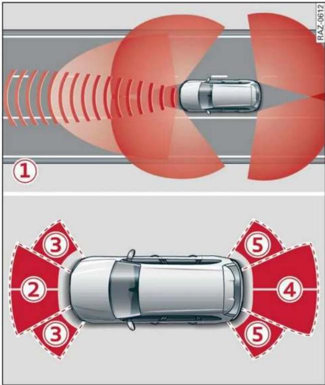
Fig. 91 Diagram: sensor detection areas

natural_image
Side profile illustration of a silver SUV with a red accent line, no text or symbols presentFig. 92 Diagram: coverage area of the rearview camera
The assist systems analyze the data from various sensors and cameras installed in the vehicle. Do not use any assist systems if there is damage to the vehicle in an area where sensors and cameras are located or on the vehicle underbody, or if the vehicle was involved in a collision. The functionality of the sensors and cameras could be impaired, or they could malfunction. Have an authorized Audi dealer or authorized Audi Service Facility check their function.
Radar sensors
Depending on the vehicle equipment, the area surrounding the entire vehicle may be detected fig. 91 ①.
The wheel sensors on the rear corners of the vehicle are positioned so that the adjacent lanes to the left and right are detected on roads with a normal lane width.
Ultrasonic sensors
Depending on vehicle equipment, various areas may be displayed in the MMI using the ultrasonic sensors fig. 91.
The range of the displays depends on the location of the ultrasonic sensors:
② Approximately 4 ft (1.20 m)
③ Approximately 3 ft (0.90 m)
④ Approximately 5.2 ft (1.60 m)
⑤ Approximately 3 ft (0.90 m)
Cameras
Use the camera image on the display to assist you only if it shows a good, clear picture. Keep in mind that the image in the display is enlarged and distorted. Under certain circumstances, objects may appear different and unclear on the display.
The rearview camera can only detect the area marked in red fig. 92. Only this area is displayed on the upper display .

WARNING
Sensors and cameras have spots in which the surrounding area cannot be detected. Objects, animals, and people may only be detected with limitations may not be detected at all. Always monitor the traffic and the vehicle's surroundings directly and do not become distracted.

Note
- Obstacles may disappear from the measurement range when approaching them, even if they were already detected.
- In some situations, the ability of the sensors and cameras to detect and display certain objects may be limited.
- Objects located above the coverage area, such as bumpers on parked cars, garage doors that are partially open, or objects that are hanging
- Low obstacles
- Narrow objects, such as barrier chains, foliage, poles, or fences
- Projecting objects, such as trailer draw bars
- Objects with certain surfaces and structures, such as fabric

Tips
- The sensors and cameras and the areas around them must not be obstructed because this can impair the function of the systems that depend on them. Make sure that the sensors and cameras are free of snow, ice, and other deposits. Do not use any accessories, stickers, or other objects that extend into the range of the sensors and cameras.
- On vehicles that have factory-installed license plate brackets on the front of the vehicle, the brackets may only be replaced with ones that are the same size and made of the same material. Do not install any license plate brackets on the front of vehicles that do not have factory-installed brackets. Otherwise, the function of the system could be impaired.
- The function of the sensors and cameras may be limited when light and visibility conditions are poor, for example when driving into a tunnel, when there is glare, or when there are reflective objects.
- External ultrasonic sensors, such as those in other vehicles, can interfere with the sensors.
- The coverage areas of the sensors and cameras fig. 91 are diagrams and do not represent a true-to-scale image of the sensor ranges.
- For an explanation on conformity with the FCC regulations in the United States and the
Industry Canada regulations, see ⇒ page 300.
Locations of the sensors and cameras

Fig. 93 Front area: sensors and cameras

Fig. 94 Rear area: sensors and cameras
Front area
Depending on the vehicle equipment, the following sensors and cameras may be installed:
– Laser scanner in the front in the radiator grille
⇒ ⚠️
- Camera behind the windshield
- Peripheral cameras on the exterior mirrors
– Front peripheral camera in the radiator grille
– Night vision camera in the radiator grille
– Front ultrasonic sensors
– Radar sensors at the front corners of the vehicle
– Radar sensor in the front in the radiator grille
Rear area
Depending on the vehicle equipment, the following sensors and cameras may be installed:
– Rearview camera in the luggage compartment lid
– Radar sensors at the rear corners of the vehicle
– Rear ultrasonic sensors

WARNING
Applies to: vehicles with laser scanner
- The surface of the laser scanner can become hot during operation, which increases the risk of burns.
- The laser scanner contains a class 1 laser in accordance with IEC 60825-1:2014. When used according to regulations, the laser is not dangerous. Opening the laser module and removing covers is not permitted. Doing so could cause permanent injuries to the eyes.
– Any repair work on the laser module must be performed by an authorized Audi dealer or authorized Audi Service Facility; otherwise the vehicle's operating license may be voided. Incorrect repairs may cause limited functionality and eye damage.

Tips
Applies to: vehicles with laser scanner
- The possible emissions are below the threshold for class 1 lasers.
- Complies with 21 CFR 1040.10 and 1040.11 except for deviations pursuant to Laser Notice No. 50, dated June 24, 2007.

Tips
– The locations of the sensors may differ slightly depending on vehicle equipment.
- Some sensors are installed under vehicle components and cannot be seen from the outside.
- For an explanation on conformity with the FCC regulations in the United States and the Industry Canada regulations, see page 300.
Switching the systems on and off

Fig. 95 Center console: driver assistance systems button
Description
You can switch some assist systems on and off in the MMI. Depending on the equipment, it may be in the standard display or the profile selection.
▶ Press the Ⓗ button, or
▶ Applies to: MMI: Select on the home screen: VEHICLE > Driver assistance.
Standard display
Applies to: vehicles with standard display
▶ To switch a system on or off, press Ⓐ for the desired system.
▶ To show the brief description of a system, press ⓘ for the desired system.
Profile selection
Applies to: vehicles with profile selection
▶ To select a profile, press the profile name on the upper display or press the 🔒 button repeatedly until the profile is active.
▶ To list systems included in a profile, select on the upper display.
▶ To show the brief description of a system, select ⓘ for the desired system.
▶ To switch individual systems on and off in the individual profile, select ☑ and Ⓗ for the desired systems.
The following profiles can be selected:
- Maximum - All available systems are switched on in this profile.
- individual - You can switch the systems on and off individually in this profile.
- Basic or All off - Only the basic systems are switched on in this profile. If no basic system is available, the profile is All off.

WARNING
Follow the safety precautions and note the limits of the assist systems, sensors, and cameras page 119.

Tips
Certain settings are stored automatically in the active personal profile.
Driving information Speed warning system
Description
Applies to: vehicles with speed warning system
The speed warning system helps the driver to stay below a specified maximum speed. A warning threshold can be set in the MMI for this purpose.
Once the speed slightly exceeds the stored threshold, the speed warning system will alert the driver with an indicator in the instrument cluster and a warning tone. Once the speed drops below the stored maximum speed, the indicator will turn off.
Setting a threshold is recommended if you would like to be reminded when you reach a certain maximum speed. Situations where you may want to do so include driving in a country with a general speed limit or if there is a specified maximum speed for winter tires.

Tips
Regardless of the speed warning system, you should always monitor your speed using the speedometer and make sure you are following the legal speed limit.
Setting the warning threshold
Applies to: vehicles with speed warning system
▶ Applies to: MMI: Select on the home screen: VEHICLE > Driver assistance > (○) > Speed warning.

Tips
Certain settings are stored automatically in the active personal profile.
Messages
Applies to: vehicles with speed warning system


Manually set speed limit XX mph
(km/h) exceeded
The stored speed was exceeded.
Camera-based traffic sign recognition
Description
Applies to: vehicles with camera-based traffic sign recognition

Fig. 96 Instrument cluster: traffic sign recognition
The traffic sign recognition shows the traffic signs detected by the front camera in the instrument cluster display and in the head-up display*. Data from the navigation system is also included in the display. Up to three traffic signs can be displayed in the instrument cluster at once. The speed limit that is currently applicable is displayed in the status line. If necessary, it will be hidden if the system detects that turning right is prohibited at a red light. The display in the head-up display* can be switched off page 25.
Within the limits of the system and depending on the market, speed limit restrictions ① in school zones, highways, construction zones, or at night may be displayed.
Limitations
The traffic sign recognition is subject to certain system limitations and may be unavailable or only partially available in the following situations:
- When visibility is poor, such as in snow, rain, fog, or heavy spray
- When there is glare, for example from oncoming traffic or the sun
- At high speeds
- If the camera's visual field page 120 is covered, for example by dirt or stickers. Cleaning information page 270
-
If the traffic signs are completely or partially covered, for example by trees, snow, dirt, or other vehicles
-
If traffic signs do not conform to the standard format
- If traffic signs are damaged or bent
- If traffic signs are displayed on sign holders with electronic signs
- If the traffic signs or the roadways have changed, and the navigation data is no longer up-to-date

WARNING
- Follow the safety precautions and respect the limits of the assist systems, sensors, and cameras page 119.
- Under some circumstances, traffic sign recognition may not detect traffic signs correctly or detect them at all. As a result, the system may not display the correct speed limit or any speed limit.

Tips
– Traffic sign recognition does not adapt your vehicle's speed to match the speed limit.
- The display in the instrument cluster is based on the units of measurement used for speed in the country where the vehicle is being operated. As a result, a display of 50 in the instrument cluster can mean either mph or km/h, depending on the country.
Operation
Applies to: vehicles with camera-based traffic sign recognition
Accessing traffic sign recognition
▶ Select in the instrument cluster: vehicle functions tab > Traffic signs.
Setting a traffic sign based speed warning
▶ Applies to: MMI: Select on the home screen: VEHICLE > Driver assistance > (○) > Speed warning.
You can select a warning threshold. If it is exceeded, then the current detected speed limit will be shown in the display with an exclamation point for the duration that it is exceeded and it will blink for a short time.

Tips
Certain settings are stored automatically in the active personal profile.
Messages
Applies to: vehicles with camera-based traffic sign recognition

Traffic sign recognition: currently unavaila- . Camera view limited due to surroundings
The camera's visual field is covered. Clean the windshield.

Traffic sign recognition: currently limited. e owner's manual
This message appears if navigation system data is not available, for example on newly-constructed roads. The speed limit display will be temporarily limited, which increases the risk of an incorrect display. If this message continues to appear, drive immediately to an authorized Audi dealer or authorized Audi Service Facility to have the malfunction repaired.
No traffic sign information available
Depending on the area, there is no valid navigation data and no speed limits were detected. This may also appear if there is a recommended speed, but no speed limit (for example when driving on and off the expressway).
Malfunction! See owner's manual
The system may not function correctly so it has been switched off. See an authorized Audi dealer or authorized Audi Service Facility for assistance.
Function currently unavailable. See owner's manual
If this message appears on vehicles without camera-based traffic sign recognition, then the traffic light information function is currently unavailable. See page 127.
Traffic light information
Description
Applies to: vehicles with traffic light information

Fig. 97 Instrument cluster: traffic light information display
The traffic light information gives you a speed recommendation in order to reach the next traffic light when it is green ①, or it informs you of the wait time at the next red light ②. Once traffic light data is received, the traffic light information will be displayed in the instrument cluster and in the head-up display*. If the vehicle is in an area with traffic light information but cannot receive a traffic light signal, then a gray traffic light symbol will be displayed ③.
General information
The traffic light information is subject to system limitations and may be unavailable or only partially available in the following situations:
- If the permitted speed limit is exceeded
- If driving below a certain speed limit
- If the next traffic light is less than approximately 100 feet (30 m) away
- If the estimated wait time at a red light is less than four seconds
- If there is no traffic light data available
- If emergency response vehicles or public transit systems are active
- If traffic lights are in construction zones or being serviced
- If there are warnings from the camera-based traffic sign recognition*
- If the camera-based traffic sign recognition* is malfunctioning or not available
-
If the data connection has been interrupted
-
If data transmission is deactivated in the privacy settings
- If the subscription has expired
If this is the case, the menu item will be grayed-out or it will not be possible to select it.

WARNING
- When traffic light information is shown, also always pay attention to the traffic situation, the distance to other vehicles, and the area around the vehicle. The driver is always responsible for assessing the traffic situation.
- Always adapt your speed to the current weather, road and traffic conditions. The displayed information must never cause you to ignore legal traffic regulations and pose a safety risk.
- Regardless of the traffic light information, you should always monitor your speed using the speedometer and make sure you are adhering to the legal speed limit.
- The traffic light information does not adjust your vehicle's speed to the speed recommendation shown in the display.
– Follow the safety precautions and note the limits of the assist systems, sensors, and cameras page 119.

Tips
- Traffic light information was only available in select cities at the time this manual was printed.
– Traffic light information is not available nationwide. - The functions depend on the navigation data* being up-to-date and correct identification by the traffic sign recognition*.
- Incorrect values from the camera-based traffic sign recognition* or outdated navigation system* map data can result in missing or incorrect display images.
- Certain traffic lights can automatically adjust to the current traffic situation. If this occurs, the display of traffic light information can change suddenly.
- The traffic signs on the road always take priority over the display. The driver is always responsible for adhering to the regulations applicable in the country where the vehicle is being operated.
– Units of measurement and language settings are displayed based on how they were set in the MMI system settings page 226.
Operation
Applies to: vehicles with traffic light information
Switching traffic light information on and off
The system can be switched on and off in the MMI page 122.
Accessing traffic light information
▶ Select in the instrument cluster: vehicle functions tab > Traffic signs.
i Tips
If another tab or another function is selected in the instrument cluster, the traffic light information will appear in the status bar on the instrument cluster.
Messages
Applies to: vehicles with traffic light information
Malfunction! See owner's manual
The system could not be configured, for example due to a network malfunction. Switch the ignition off and shut down the vehicle to restart the system. Wait several minutes until the vehicle has shut down completely and then switch the ignition back on.
Function currently unavailable. See owner's manual
There is a temporary system malfunction. Check if one or more of the following situations applies and correct the issue if necessary:
– Traffic light information is switched off
– Data transmission is deactivated
- The vehicle is not equipped with traffic sign recognition.
– There is no valid license
– Traffic light information is not available in that area
Lap timer
Introduction
Applies to: vehicles with lap timer
You can record and evaluate lap times with the lap timer. You can operate the lap timer using the multifunction steering wheel page 12.
Opening the lap timer
▶ Select in the instrument cluster: vehicle functions tab > ☐ button > Lap times.
An additional indicator appears in the head-up display*.
! WARNING
Your focus should always be on driving your vehicle safely. As the driver, you have complete responsibility for safety in traffic. To reduce the risk of an accident, only use the lap timer functions in such a way that you always maintain complete control over your vehicle in all traffic situations.
i Tips
You can retrieve information from the trip computer while the lap timer stopwatch is running.
Lap times and timing
Applies to: vehicles with lap timer
Requirement: the lap timer must be open
→ page 127.
Timing laps
▶ To start timing manually, select Start lap 1 in the menu.
▶ To start timing automatically as soon as you begin to drive, select Start lap 1 by driving off or Start by driving off in the menu.
▶ To start timing a new lap after driving a lap, select New lap in the menu. This starts timing the next lap at the same time.
After completing a lap, the difference between the last lap and the previous best lap time will be indicated with “-” or “+”
Pausing timing and displaying a split time
▶ To insert a pause 🤨, select Pause in the menu.
▶ To resume timing, select Resume in the menu.
▶ To display a split time, select Split time in the menu. The split time 📋 appears for ten seconds in the instrument cluster. The current lap timing will continue running.
Canceling lap timing
The timing of the current lap will stop. The lap time will be erased and will not be included in the statistics.
▶ Select Cancel lap in the menu.
Resetting the time
▶ Select Reset times in the menu.

Tips
– A maximum of 99 lap times can be measured.
- If timing is paused, you can continue it later even if you switch the ignition off.
– Saved lap times cannot be individually deleted from the total results.
- The saved lap timer values will remain after switching the ignition off.
Lap statistics
Applies to: vehicles with lap timer
Displaying lap statistics
You can display the number of laps driven 🎨, the fastest lap “+”, the slowest lap “-”, and the average time “∅” in the instrument cluster.
▶ Select in the instrument cluster: vehicle functions tab > ☐ button > Lap statistics.
▶ Turn the thumbwheel down or up to display the individual lap times.
▶ To return to the lap timing that was started, select the ☐ button > Lap times.
Resetting lap statistics
Requirement: the lap statistics menu must be displayed.
▶ To reset the lap statistics, press and hold the left thumbwheel until the message No lap times have been recorded yet. appears.

Tips
The lap statistics list the lap times for the last 30 laps. The fastest and slowest lap times out of up to 99 measured laps are also displayed.
Acceleration measurement
Introduction
Applies to: vehicles with acceleration measurement
With the acceleration measurement, you can measure the time that you need to reach a specific speed/distance. Keep in mind that the environmental conditions and tire properties can affect the results of the measurement.
Opening the acceleration measurement
▶ Select in the instrument cluster: vehicle functions tab > ☐ button > Acceleration measure.

WARNING
Your focus should always be on driving your vehicle safely. As the driver, you have complete responsibility for safety in traffic. Only use the acceleration measurement function on closed courses to reduce the risk of accidents.
Using the acceleration measurement
Applies to: vehicles with acceleration measurement
Requirement: the acceleration measurement must be opened.
▶ Bring the vehicle to a full stop.
▶ Select and confirm the desired speed or distance.
▶ Wait briefly until the 🔍 symbol appears in the instrument cluster next to the time measurement.
▶ To start the acceleration measurement, accelerate the vehicle. The measurement ends automatically once you have reached the selected speed or distance.
Night vision assist
Description
Applies to: vehicles with night vision assist
Night vision assist helps you when it is dark by using an infrared camera to monitor the area in front of your vehicle, within the limits of the system. It can display objects up to a distance of approximately 1000 feet (300 m).
Pedestrian and wild animals are detected by measuring the temperature difference between the object and the background. Pedestrians and wild animals will not be detected if the temperature difference is too small. The pedestrian and wild animal marking feature is deactivated at temperatures above approximately 77 °F (25 °C) and when it is light outside.
The thermal image detected by the camera is displayed in the instrument cluster. Warm areas generally appear lighter and cold areas appear darker.
The camera for the night vision assist is located in the vehicle's radiator grille page 121. Make sure the night vision camera is not covered by stickers, deposits, or any other obstructions because this can impair the night vision assist function. Follow the information about cleaning page 270.

WARNING
- Follow the safety precautions and note the limits of the assist systems, sensors, and cameras page 119.
– Night vision assist can only detect pedestrians and wild animals located within the range of the infrared camera.
– Night vision assist cannot detect pedestrians or wild animals and mark them if:
- They are not in an upright position, for example if they are sitting or lying down and/or
- The silhouette in the display appears incomplete or interrupted, for example because the pedestrian is partially behind a vehicle or an animal is partially covered by tall grass.
- Never attempt to swerve around animals if doing so would endanger you or other road users.

Tips
- Even though the system evaluates the shape and heat given off by all detected objects, there are limits to the system. There may be false warnings.
- For technical reasons, the image pauses in split second intervals.
Switching on and off
Applies to: vehicles with night vision assist
The system can be switched on and off in the MMI page 122.
▶ The AUTO light function must be selected for the night vision assist to automatically activate when it is dark.
▶ Switch on the low beams manually to activate night vision assist immediately. To do so, press ① on the light switch module and select ≡D.
When activated, the 12 tab appears in the instrument cluster.
▶ Select in the instrument cluster: tab %

Tips
When the night vision assist tab is selected in the instrument cluster and the low beams are switched off, the thermal image display disappears only after you have exited the tab.
Marking and warning
Applies to: vehicles with night vision assist
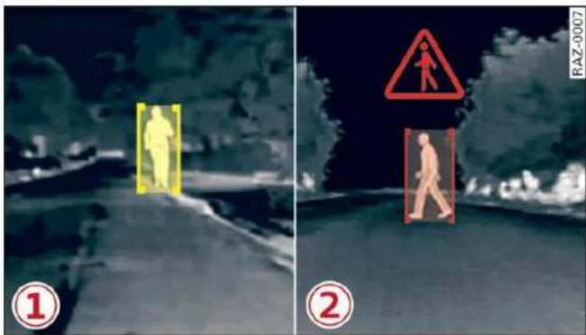
Fig. 98 Instrument cluster: pedestrian marking and warning
Highlighting detected pedestrians and wild animals
Within the limits of the system, the night vision assist can detect pedestrians and wild animals that are between approximately 32 feet (10 m) and 295 feet (90 m) in front of the vehicle and within the detection zone. Animal recognition is not active within highly developed areas. The system only detects large wild animals such as deer. When it is dark outside and the low beams are switched on, detected objects are marked in yellow ①, within the limits of the system.
Pedestrian and wild animal warning
This system limits are based on the vehicle speed and steering angle. Pedestrian and wild animal warning encourages you to pay more attention.
If there are pedestrians or wild animals in front of your vehicle that could pose a danger, the system will direct your attention to this.
- Pedestrians or wild animals are highlighted in red in the instrument cluster ② and the 🔒 or 🔒 symbol turns on ②.
- When the head-up display* is switched on, the additional indicator 🔒 or 🔒 appears.
– A chime will sound if something is detected. - If the night vision assist thermal image is replaced by another display (such as the on-board computer), the red 🔒 or 🔒 indicator light will appear if there is a pedestrian or wild animal warning.
The symbol will appear when pedestrian and wild animal detection is not available.
Marking light\*
To direct the driver's attention to a pedestrian, the headlights can flash on the pedestrian when there is a pedestrian warning.
This occurs at speeds above approximately 35 mph (60 km/h) if you are outside of illuminated areas and no detected vehicles are shown. The marking light is not used for wild animals. The high beam assistant* controls the marking light*⇒ page 48.
Adjusting the contrast
Applies to: vehicles with night vision assist
Requirement: the night vision assist must be switched on and the 12 tab must be displayed.
▶ Applies to: MMI: Select on the home screen:
VEHICLE > Driver assistance > (○) > Night vision assist.
▶ To set the desired contrast, move the slider.

Tips
Certain settings are stored automatically in the active personal profile.
Messages
Applies to: vehicles with night vision assist
Night vision assist: currently unavailable. See owner's manual
The system is not functioning correctly so it has been switched off. If this malfunction persists, drive immediately to an authorized Audi dealer or authorized Audi Service Facility to have the malfunction repaired.
Driver assistance
Cruise control system
Description
Applies to: vehicles with cruise control system
The cruise control system assists the driver in maintaining a constant speed above approximately 15 mph (20 km/h). The system maintains the desired speed by braking and accelerating.

WARNING
- Always pay attention to the traffic around your vehicle when the cruise control system is in operation. As the driver, you are always responsible for controlling your vehicle speed and the distance between your vehicle and other vehicles.
- For safety reasons, cruise control should not be used in the city, in stop-and-go traffic, on winding roads, and when road conditions are poor (such as ice, fog, gravel, heavy rain, and conditions that could lead to hydroplaning), because this increases the risk of an accident.
- Switch the cruise control off temporarily when driving in turning lanes, highway exits, or in construction zones.
- To reduce the risk of an accident, you should only resume the stored speed if it is suitable for the current traffic conditions.

Note
Before driving downhill a long distance on a steep hill, decrease your speed and select a lower gear. This makes use of the engine braking effect and reduces the load placed on the brakes.

Tips
The brake lights turn on when the brakes are applied automatically.
Switching the system on
Applies to: vehicles with cruise control system

Fig. 99 Lever: switching on the cruise control system
Requirement: the ignition must be switched on.
▶ To switch the system on, pull the lever toward you to position ①.
The CRUISE or 📋 indicator light and the corresponding message will appear in the instrument cluster.

WARNING
If the brakes are malfunctioning (for example, overheating) while the cruise control system is switched on, the regulating functions may shut off automatically.
Preselecting or activating a cruise control speed
Applies to: vehicles with cruise control system
When the vehicle is stationary, you can preselect the cruise control speed or activate the speed while driving.
Requirement: the system must be switched on.
▶ To preselect a cruise control speed when the vehicle is stationary, tap the lever toward ⊕/⊖ → page 131, fig. 99.
▶ To activate the cruise control speed, pull the lever toward position ① while driving.
▶ To set the current driving speed as the cruise control speed, press the button Ⓐ on the lever.
The active cruise control speed is indicated with the CRUISE or indicator light in the instrument cluster.
An additional indicator appears in the head-up display*.
Changing the cruise control speed
Applies to: vehicles with cruise control system
▶ To increase or decrease the cruise control speed in small increments, tap the lever up to the first level toward ⊕/⊖ ⇔ page 131, fig. 99.
▶ To increase or decrease the cruise control speed in larger increments, tap the lever up to the second level toward ⊕/⊖.
▶ To increase or decrease the cruise control speed continuously, tap and hold the lever at the first or second level toward ⊕/⊖.
Overriding or deactivating the cruise control speed
Applies to: vehicles with cruise control system
You can override or deactivate the cruise control system. When you deactivate the system, your cruise control speed will be stored and you can resume that speed.
Requirement: the system must be switched on and activated.
Overriding
▶ To temporarily override the cruise control speed, press the accelerator pedal.
▶ Once you release the accelerator pedal, the system will adjust back to the stored cruise control speed.
If you override the cruise control system for a long period of time, the cruise control system will be deactivated. The CRUISE or indicator light will be displayed and the cruise control speed will be saved.
Deactivating
▶ To deactivate the cruise control speed, press the lever toward ② (not locked into place)
⇒ page 131, fig. 99, or
▶ Press the brake pedal.

WARNING
Resting your foot on the accelerator pedal could override the cruise control. This will prevent braking interventions by the system.
Switching the system off
Applies to: vehicles with cruise control system
When you switch the system off completely, the cruise control speed will be deleted.
Requirement: the system must be switched on.
▶ To switch the system off, press the lever toward ② (locked into place) ⇒ page 131, fig. 99, or
▶ Switch the ignition off.
Message
Applies to: vehicles with cruise control system
CRUISE / Speed control system: currently unavailable. See owner's manual
If the indicator light turns on and this message appears, the cruise control system has been deactivated. There is a temporary malfunction, for example the brakes are overheating. Switch the cruise control system on again later.
Efficiency assist
Description
Applies to: vehicles with efficiency assist
Efficiency assist can assist the driver with predictive information in order to reduce fuel consumption. Depending on vehicle equipment, the system may access data from the navigation system, the camera behind the windshield, and the radar sensors.
Adjusting the efficiency assist
You can adjust efficiency assist functions individually. The settings depend on the vehicle equipment.
– Predictive messages page 133.
– Predictive control page 134.
- Accelerator pedal feedback page 96.
Situation symbols
Depending on vehicle equipment, the following symbols may be shown. The symbols indicate the situation to which the efficiency assist is responding.
Some symbols only appear if Predictive messages are switched on, and some symbols only appear if Predictive control is switched on and adaptive cruise assist* is active.
| Symbol | Description |
 | Slow down(predictive messages only) |
 | Speed limit(example) |
 | Exit ahead |
 | Intersection ahead |
 | Traffic circle ahead |
 | (predictive control only) If the indicator light turns on in green and red, it is indicating that there is a difference between the speed limit and the set speed. |

WARNING
Follow the safety precautions and note the limits of the assist systems, sensors, and cameras page 119.

Tips
- The functions depend on the navigation data* being up-to-date and correct identification by the traffic sign recognition*.
- The system only detects traffic signs that specify a speed limit.
- The display in the instrument cluster is based on the units of measurement used for speed in the country where the vehicle is being operated. As a result, a display of 50 in the instrument cluster can mean either km/h or mph, depending on the country.
- Except for the road network, which is recorded in the navigation system's map infor-
mation, certain functions may not be available.
- Certain settings are stored automatically in the active personal profile.
Predictive messages
Applies to: vehicles with efficiency assist
The symbol 📋 appears in the instrument cluster display if efficiency assist recommends removing your foot from the accelerator pedal.
Additional symbols that indicate the situation to which the efficiency assist is reacting are shown in the Driver assistance display page 133.
Requirements
- The cruise control system* or the adaptive cruise assist* controls must not be active.
- The vehicle speed must be at least 20 mph (30 km/h).
- The remaining distance until the situation is reached must be large enough to allow the system to react to the situation.
Switching Predictive messages on or off
Applies to MMI: Select on the home screen: VEHICLE > Efficiency assist > Predictive messages.

WARNING
- Follow the safety precautions and note the limits of the assist systems, sensors, and cameras page 119.
- Pay attention to traffic and the area around your vehicle when efficiency assist is switched on. The driver is always responsible for assessing the traffic situation.

Tips
- The traffic signs on the road always take priority over the display. The driver is always responsible for adhering to the regulations applicable in the country where the vehicle is being operated.
-
When a route is planned using the navigation system*, then system displays messages based on an assumed route. Without route guidance, the system displays messages based on an assumed route.
-
The wording of the message may vary depending on the selected Audi drive select* mode and the selected gear. No messages are displayed when in the "S" driving program.
- Certain settings are stored automatically in the active personal profile.
Predictive control
Applies to: vehicles with adaptive cruise assist and efficiency assist
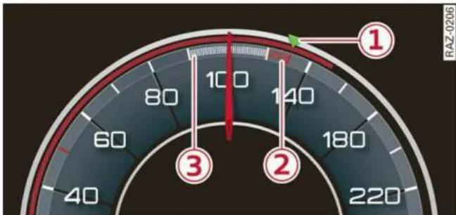
gauge
| Gauge | Value | |-------|-------| | 1 | 100 | | 2 | 180 | | 3 | 60 |Fig. 100 Instrument cluster: speedometer: predictive control display
During predictive control 1) , the adaptive cruise assist uses data from the efficiency assist. The system adapts the speed set in the adaptive cruise assist to the speed limits that are detected and the layout of the road. After that, the system accelerates up to the speed that was set.
After switching on the ignition, the availability of predictive control is indicated by a message when the adaptive cruise assist is first activated.
Requirements
- The adaptive cruise assist must be actively regulating page 138.
- The system can only react to speed limits that are 20 mph (30 km/h) or higher.
Display in the speedometer
The display in the speedometer is not available in all layouts*.
① The marking shows the set speed (regulated speed that was set by the driver or by predictive control).
② The red band shows the difference between the speed limit and the set speed that is set.
③ The gray band shows if the vehicle speed is planned to drop below the set speed due to the road layout.
Overriding control
The driver can override the predictive control at any time by pressing the accelerator or brake pedal. If the system changes the vehicle speed to adapt to speed limits, you can change the speed using the lever page 138, fig. 106.
Setting predictive control
You can switch off predictive control functions or adjust them individually. The settings depend on the vehicle equipment.
Applies to: MMI: Select on the home screen: VEHICLE > Driver assistance > (💡) > Adaptive cruise assist > Predictive control.
Possible settings:
Set speed limit – Adjusts to speed limits. You can also set With tolerance if desired. In this scenario, you may fall below or exceed the set speed in favor of increased efficiency.
Adjustment to curves along route – Can be switched Off or be set individually from Slow to Fast. The setting influences vehicle handling with predictive control, for example the speed for driving through curves.
Messages
If 📁 and a message with Adaptive cruise assist: Predictive control is displayed when there is a malfunction, the efficiency assist functions are unavailable or limited.
A message that indicates the cause and possible solution may appear with some displays. The weather conditions may be too poor or a sensor may be covered. Clean the area in front of the sensors page 121 and try to turn on the systems again later.
If the malfunction remains, drive to an authorized Audi dealer or authorized Audi Service Facility immediately to have the malfunction corrected.

WARNING
– Follow the safety precautions and note the limits of the assist systems, sensors, and cameras page 119.
- Pay attention to traffic and the area around your vehicle when predictive control is switched on. The driver is always responsible for assessing the traffic situation.
- The system does not consider "right of way" rules and does not respond to traffic lights, so lack of driver attention in these situations can increase the risk of an accident.
- The speed when driving through curves may be different from what you as a driver would do or may not be suitable for the weather and road conditions. If necessary, apply the brakes and reduce the selected speed to be maintained in the Adjustment to curves along route setting to reduce the risk of an accident.

Tips
- Predictive control can exceed or drop below the maximum permitted speed. The driver is responsible for adhering to the permitted speed limit.
- The traffic signs on the road always take priority over the display. The driver is always responsible for adhering to the regulations applicable in the country where the vehicle is being operated.
- If a speed limit is detected, the marking ① of the set speed limit will be adjusted even if the adaptive cruise assist is not actively regulating.
- Control by the system depends on which adaptive cruise assist driving program is set or on the selected Audi drive select* mode.
- After switching on the ignition and first driving onto a freeway or similar road with-
out a speed limit, the system will regulate the speed to 80 mph (130 km/h) 1) . Then the system adjusts to the last speed set by the driver.
– There is no adaptation to speed limits when driving through highway interchanges and when driving on or off the expressway.
- The system can fail to provide control or the control may be faulty if the values from the camera-based traffic sign recognition* are incorrect or the navigation system map data is outdated.
- When route guidance is switched on, the system adapts to the route provided by the navigation system. Driving without route guidance or leaving a route can result in faulty control.
– Certain settings are stored automatically in the active personal profile.
Adaptive cruise assist
General information
Applies to: vehicles with adaptive cruise assist
Depending on the vehicle equipment, the adaptive cruise assist may consist of the following functions:
Within the limits of the system, the adaptive speed assist assists the driver in controlling the speed and the set distance to the vehicle driving ahead. If the system detects a vehicle driving ahead, the adaptive speed assist can brake and accelerate your vehicle within the limits of the system. On open roads with no traffic, it functions like a cruise control system. The stored speed is maintained. When approaching a vehicle driving ahead, the adaptive speed assist automatically brakes to match that vehicle's speed and then maintains the set distance as much as possible. Once the system does not detect a vehicle driving ahead, adaptive speed assist will accelerate up to the set speed.
The additional lane guidance assists the driver with corrective steering in order to stay in the lane. You can adjust if the adaptive cruise assist
will provide support with lane guidance ⇒ page 139, Switching lane guidance on and off.
In stop-and-go traffic and in traffic jams, the vehicle may brake to a full stop and then may also start driving again automatically under certain conditions.
Applies to: vehicles with efficiency assist: Predictive control can adjust the speed based on traffic and road conditions page 134, Predictive control.

WARNING
Follow the safety precautions and note the limits of the assist systems, sensors, and cameras page 119.

Tips
For an explanation on conformity with the FCC regulations in the United States and the Industry Canada regulations, see page 300.
Limitations
Applies to: vehicles with adaptive cruise assist

Fig. 101 Example: vehicle changing lanes and stationary vehicle

natural_image
Diagram showing a car driving on a curved road with red traffic wave signals, no text or symbols presentFig. 102 Example: driving into a curve
In some situations, the adaptive cruise assist function is limited and you must assume control of the vehicle when necessary, for example by applying the brakes.
- If a vehicle that was already detected ① turns or changes lanes, the adaptive cruise assist will react to the vehicle ahead of it ②.
- When driving into a curve fig. 102 and out of a curve, the adaptive cruise assist may react to a vehicle in the adjacent lane and apply the brakes. You can override the system by pressing the accelerator pedal briefly.
- The adaptive cruise assist works with the various sensors and cameras in the vehicle. Vehicles can only be detected once they are within the area and range covered by the sensors page 120, fig. 91.
- When driving around tight curves, a vehicle driving ahead that was previously detected may no longer be detected, and the adaptive cruise assist may accelerate unexpectedly.
- The adaptive cruise assist does not react to a stationary vehicle in the same lane if the system expects that you can easily drive around the stationary vehicle by turning the steering wheel.
- The adaptive cruise assist may not react to stationary obstacles, such as the end of a traffic jam, especially at high speeds.
- The adaptive cruise assist has a limited ability to detect vehicles that are a short distance ahead, off to the side of your vehicle, or moving into your lane.
- Objects that are difficult to detect, such as motorcycles, vehicles with high ground clearance, or vehicles with an overhanging load, may be detected late or not detected at all.
- The adaptive cruise assist does not respond to people, animals, or objects that are crossing or approaching from the opposite direction.

WARNING
Follow the safety precautions and note the limits of the assist systems, sensors, and cameras page 119.
Display overview
Applies to: vehicles with adaptive cruise assist

gauge
| Gauge Point | Value | | ----------- | ----- | | 1 | 100 | | 2 | 80 | | 3 | 140 |Fig. 103 Instrument cluster: display in speedometer

Fig. 104 Instrument cluster: driver assistance display
Indicator lights and messages in the speedometer ① - ③ inform you about the driving situation and the settings. In the Driver assistance display ④ - ⑩, you can find more detailed information about the system. The displays depend on the country and equipment.
Display in the speedometer
The display in the speedometer is not available in all layouts*.
① Marking for the set speed
② Current vehicle speed
③ Available speed range for adaptive cruise assist (example)
Image in the Driver assistance display
The display only appears when the Driver assistance display is open in the on-board computer page 15.
④ Messages and settings
⑤ Detected vehicle driving ahead
⑥ Set target distance
⑦ The set distance is not met. The distance bars will be colored red from the bottom upward.
⑧ Your vehicle
⑨ Availability of lane departure warning and lane guidance for adaptive cruise assist
⑩ Availability of lane guidance for adaptive cruise assist
Indicator lights
- The speed/distance control is active. No vehicles were detected ahead. The stored speed is maintained.
- The speed/distance control is active. A vehicle was detected ahead. The adaptive cruise assist controls the speed and distance from the vehicle driving ahead, and accelerates and brakes automatically.
- The speed/distance control is active but the vehicle is not ready to drive. A vehicle was detected ahead. Your vehicle is stationary and will not start driving automatically.
- The speed/distance control is active but the vehicle is not ready to drive. No vehicles were detected ahead. Your vehicle is stationary and will not start driving automatically.
- The automatic braking is not enough to maintain a sufficient distance to a vehicle driving ahead. You must intervene page 142, Driver intervention request.
- The indicator light turns on if the system does not detect enough steering activity by the driver. Always keep your hands on the steering wheel so you can be ready to steer at any time. The indicator light will also turn off, for example if the steering power from the system is not sufficient and adaptive cruise assist is canceled page 140, Steering intervention request.
! WARNING
Follow the safety precautions and note the limits of the assist systems, sensors, and cameras page 119.
Using adaptive cruise assist
Applies to: vehicles with adaptive cruise assist

Fig. 105 Lever: using adaptive cruise assist

Fig. 106 Operating lever: changing the speed
Switching on
▶ To switch on the adaptive cruise assist, pull the lever up to position ① until it engages.
Storing the speed and activating regulation
If you have switched the system on, you can set the current speed as the “regulated speed” and activate regulation:
▶ Press the SET button ②. The set speed is indicated with a marking in the speedometer ① → page 137, fig. 103 and shown in the instrument cluster ⇒ !.
▶ To store the speed when stationary, the brake pedal must also be pressed.
You can set any speed between 20 mph (30 km/h) and the maximum possible speed range ③ ⇒ page 137, fig. 103.
Pausing cruise control
The control can be stopped at any time:
▶ While driving or when the vehicle is stationary: Press the lever away from you in the direction of the arrow. Or
▶ While driving: Press the brake pedal.
The indicator light turns off.
Resuming regulation
The previously set speed can be resumed at any time after a pause.
- To resume cruise control while driving, pull the lever toward you in the direction of the arrow. - To resume cruise control when stationary, pull the lever toward you in the direction of the arrow while pressing the brake pedal.
Changing the speed
▶ To increase or decrease the set speed in smaller increments, briefly tap the lever toward + or - to the first level.
▶ To increase or decrease the set speed in larger increments, briefly tap the lever toward ⊕ or ⊙ to the second level.
▶ To increase or decrease the set speed quickly, hold the lever toward ⊕ or ⊖ until the marking in the speedometer ① ⇒ page 137, fig. 103 has reached the desired speed.
Preselecting a speed
You can also preselect the speed when adaptive cruise assist is not active by moving the lever in the desired direction (+)/(-). Activate the previously selected speed by pulling the lever toward you in the direction of the arrow.
Switching off
If you do not want to use the adaptive cruise assist for a longer period of time, you can switch it off.
▶ To switch off the adaptive cruise assist, push the lever away from you to position Ⓞ until it engages.
The indicator light and the set speed will turn off.

WARNING
- Follow the safety precautions and note the limits of the assist systems, sensors, and cameras page 119.
- The activated adaptive cruise assist is only an assist system, and the driver is still
responsible for controlling the vehicle. The driver is especially responsible for braking, steering, starting to drive, and controlling the speed and the distance from other vehicles.
- Turn on the adaptive cruise assist only if the surrounding conditions permit it. Always adapt your driving style to the current visual, weather, road, and traffic conditions.
- Switch the adaptive cruise assist off temporarily when driving in turning lanes or highway exits. This prevents the vehicle from accelerating to the stored speed when in these situations.
- If you press the SET ② button when driving at speeds below 20 mph (30 km/h), then 20 mph (30 km/h) will be set because that is the minimum speed that can be set. If no vehicle is detected ahead of you, the vehicle will accelerate up to that speed.
i Tips
- Always keep your hands on the steering wheel so you can be ready to steer at any time. The driver is always responsible for adhering to the regulations applicable in the country where the vehicle is being operated.
- If you switch the ignition or the adaptive cruise assist off, the stored speed is erased for safety reasons.
- When the adaptive cruise assist is switched on, the ESC and the ASR are switched on automatically.
- The system cannot be switched off or it may be interrupted if the road exceeds the maximum possible grade for safe operation.
Switching lane guidance on and off
Applies to: vehicles with adaptive cruise assist and lane guidance
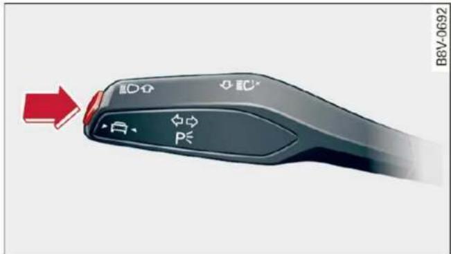
Fig. 107 Turn signal lever: button for lane guidance and lane departure warning (example)
Within the limits of the system, lane guidance provides corrective steering to assist the driver with keeping the vehicle in the center of the lane as much as possible. This feature can be deactivated.
Switching lane guidance on and off
Requirement: lane guidance must be preselected in the MMI page 143.
▶ To activate/deactivate the availability of the lane guidance, press the button on the turn signal lever fig. 107.
When adaptive cruise assist is actively regulating and lane guidance is switched on, the system will assist the driver with corrective steering.
Overview of displays and lane guidance limitations
The indicator ⑩ in the Driver assistance display indicates the availability of lane guidance ⇒ page 137, fig. 104.
- Lane guidance is active.
- Lane guidance is not active.
If the / or \ indicator light turns on white on at least one side, or the 🕒 indicator light turns on white in the Driver assistance display, then lane guidance is not active. This may be due to the following reasons:
– The necessary lane marker lines have not been detected (for example, in a construction zone
or because the lines are obstructed by snow, dirt, water, or lighting)
– The lane is too narrow or too wide
– The curve is too narrow
- The driver's hands are not on the steering wheel
– Visibility is obstructed by a rise or dip.
– The turn signal was activated.
Steering intervention request
If no steering activity is detected or the steering power from the system is not sufficient, the driver steering intervention request will alert the driver using audio and visual signals. Take over the steering and keep your hands on the steering wheel so that you will be ready to steer at any time. The system will become inactive after a short time and will only be active again later.
If the driver does not take over steering, adaptive cruise assist will be canceled. If the vehicle is equipped with emergency assist and it is ready to function, it will be activated if possible ⇒ page 155.

WARNING
Follow the safety precautions and note the limits of the assist systems, sensors, and cameras page 119.

Tips
- Always keep your hands on the steering wheel so you can be ready to steer at any time. The driver is always responsible for adhering to the regulations applicable in the country where the vehicle is being operated.
- It is recommended to only switch on lane guidance on well-constructed roads.
- Certain settings are stored automatically in the active personal profile.
- The fig. 107 button switches lane guidance availability and the lane departure warning on or off simultaneously, if lane guidance is preset in the adaptive cruise assist settings.
Setting the distance
Applies to: vehicles with adaptive cruise assist

Fig. 108 Operating lever: setting the distance
If you adjust the speed, you must also change the time gap to the vehicle driving ahead. The higher the speed, the greater the distance that is needed.
- Tap the rocker switch to display the distance that is currently set.
▶ To increase or decrease the distance in increments, tap the switch again toward ⊕ or ⊖.
The newly-set distance will be shown briefly, for example with the indicator light. In the Driver assistance display, a graphic display is shown instead of the indicator lights page 137, fig. 104. The display matches the functions of the indicator lights.
When approaching a vehicle driving ahead, the adaptive cruise assist brakes to the set speed and then maintains the set distance. If the vehicle driving ahead accelerates, then the adaptive cruise assist will also accelerate up to the speed that you have set.
The following distances can be set:
| Symbol | Meaning |
| The time between is approximately 1 second. This setting corresponds to a distance of approximately 92 feet (28 m) when traveling at 62 mph (100 km/h). | |
| The time between is approximately 1.3 seconds. This setting corresponds to a distance of approximately 118 feet (36 m) when traveling at 62 mph (100 km/h). | |
| The time between is approximately 1.8 seconds. This setting meets the general recommendation of “half the speed shown on the speedometer”. This corresponds to a distance of approximately 164 feet (50 m) when traveling at 62 mph (100 km/h). | |
| The time between is approximately 2.4 seconds. This setting corresponds to a distance of approximately 219 feet (67 m) when traveling at 62 mph (100 km/h). | |
| The time between is approximately 3.6 seconds. This setting corresponds to a distance of approximately 328 feet (100 m) when traveling at 62 mph (100 km/h). |

WARNING
Follow the safety precautions and note the limits of the assist systems, sensors, and cameras page 119.

Tips
- When setting the distance, the driver is responsible for adhering to any applicable legal regulations.
- Depending on the selected driving program and distance, driving behavior when accelerating may vary from moderate to sporty page 143, Adjusting the adaptive cruise assist.
- The distances provided are specified values. Depending on the driving situation and how the vehicle ahead is driving, the actual dis-
tance may be more or less than these target distances.
Overriding control
Applies to: vehicles with adaptive cruise assist
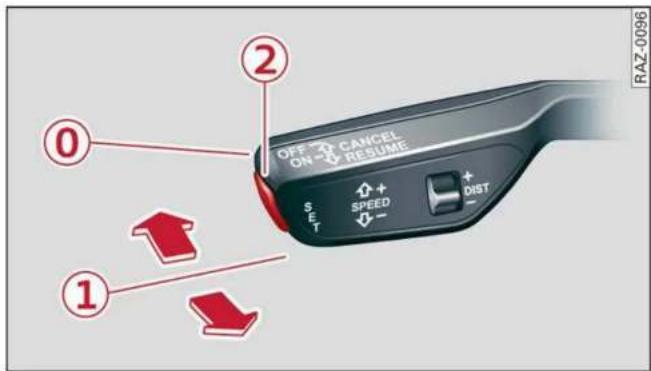
Fig. 109 Lever: overriding the control
Requirement: the adaptive cruise assist must be switched on.
Overriding control
You can completely override the control, for example when passing or if you would like to accelerate more quickly.
▶ To accelerate manually, pull the lever toward you in the direction of the arrow and hold it there, or press the accelerator pedal.
▶ To resume the usual cruise control, release the lever or remove your foot from the accelerator pedal.
When you are in the Driver assistance display, the message Overridden will appear.

WARNING
- Follow the safety precautions and note the limits of the assist systems, sensors, and cameras page 119.
- Resting your foot on the accelerator pedal could override the cruise control. Braking interventions and corrective actions by the system may not occur.
Driving in stop-and-go traffic
Applies to: vehicles with adaptive cruise assist

Fig. 110 Instrument cluster: safe start monitor
Stopping with adaptive cruise assist
The adaptive cruise assist also assists you in stop-and-go traffic. Within the limits of the system, your vehicle may brake and remain at a stop if a vehicle driving ahead stops.
Starting to drive with adaptive cruise assist 1)
As long as the message ready to drive and is displayed, your vehicle will begin driving when the vehicle ahead starts to move .
If you are stopped for several seconds, your vehicle will no longer drive autonomously for safety reasons, and the message will turn off.
▶ To extend ready to drive for several seconds or reactivate, pull the lever briefly towards you in the direction of the arrow page 141, fig. 109.
▶ To resume manual control of the vehicle, tap the accelerator pedal.
Safe start monitor
The vehicle can still start to drive even if certain obstacles are detected when starting to drive ▲. For example, if an obstacle is detected by the camera behind the windshield, the indicator light will warn you of the danger.
If you are in the Driver assistance display, the display ① ⇒ fig. 110 and the message Warning! will also appear. An audio signal will also sound. Your vehicle will drive more slowly when starting. This may also occur in some situations when there is no apparent obstacle.
- Press the brake pedal to slow your vehicle down.

WARNING
– Follow the safety precautions and note the limits of the assist systems, sensors, and cameras page 119.
- If the message ready to drive 1) appears, your vehicle will start driving even if there is an obstacle between your vehicle and the vehicle ahead. To reduce the risk of an accident, always make sure there are no obstacles between your vehicle and the vehicle driving ahead.

Tips
For safety reasons, adaptive cruise assist is only active if:
– The driver's safety belt is fastened
- All doors and the hood are closed
- Your vehicle is not stopped for a long period of time
Driver intervention request
Applies to: vehicles with adaptive cruise assist
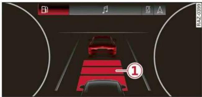
Fig. 111 Instrument cluster: request for driver intervention
The request for driver intervention instructs you to resume manual control of the vehicle if the adaptive cruise assist braking function is not able to maintain a sufficient distance to the vehicle ahead. The system will warn you of the hazard with the indicator light and the message Distance!. An audio signal will also sound.
The display ① only appears when the Driver assistance display is open in the on-board computer page 15.

WARNING
Follow the safety precautions and note the limits of the assist systems, sensors, and cameras page 119.
Adjusting the adaptive cruise assist
Applies to: vehicles with adaptive cruise assist
You can adjust the adaptive cruise assist to your own preferences. The settings depend on the vehicle equipment.
Applies to: MMI: Select on the home screen: VEHICLE > Driver assistance > (💡) > Adaptive cruise assist.
Possible settings:
Lane guidance – If lane guidance is also active when adaptive cruise assist control is active, you can switch it on or off.
Driving program – Depending on the driving program and the distance that are set, the vehicle handling will be adjusted from Sport to Moderate and the lane guidance haptic feedback will be adjusted.
Store last distance - The last distance that was set will be stored after the ignition is switched off. If the distance is not stored, distance (time distance of approximately 1.8 seconds) is automatically preset every time the ignition is switched on.
Applies to: vehicles with efficiency assist
Predictive control – When predictive control is switched on, the system reacts automatically to situations page 134.

Tips
Certain settings are stored automatically in the active personal profile.
Messages
Applies to: vehicles with adaptive cruise assist
If 📁 or 🌐 is displayed when there is a malfunction, the adaptive cruise assist functions may be unavailable or limited.
A message that indicates the cause and possible solution may appear with some displays. The weather conditions may be too poor or a sensor may be covered. Clean the area in front of the sensors page 121 and try to turn on the systems again later.
If the malfunction remains, drive to an authorized Audi dealer or authorized Audi Service Facility immediately to have the malfunction corrected.
Applies to: vehicles with narrowed road assist
Narrow area
Depending on vehicle equipment, this message appears in the Driver assistance display if the adaptive cruise assist is adjusting the speed in a narrow area, for example a construction zone.

Adaptive cruise assist: Please take over!
This message appears if the vehicle rolls back when starting on a slight incline, even though the systems are active. Press the brake pedal to prevent the vehicle from rolling or starting to move.
Applies to: vehicles with laser scanner

Adaptive cruise assist: limited availability. e owner's manual
This message appears when the sensor view is limited, for example, when weather conditions are too poor or a sensor is covered. You can switch on the adaptive cruise assist, but certain functions such as assistance in narrow areas will not be available. Under certain circumstances, some objects may be detected late or may not be detected at all. Be especially careful. However, cleaning the area in front of the sensors page 121 may correct the malfunction.
Distance warning
Description
Applies to: vehicles with distance warning

Applies to: vehicles with adaptive cruise assist
Fig. 112 Instrument cluster: display of the current distance

Applies to: vehicles with adaptive cruise assist
Fig. 113 Instrument cluster: distance warning
General information
At speeds above approximately 40 mph (65 km/h), this function measures the distance to the vehicle ahead as time. If the distance falls below the warning threshold, the system warns you of the hazard with the indicator light.
Image in the Driver assistance display
Applies to: vehicles with adaptive cruise assist
The display only appears if the Driver assistance display is selected on the on-board computer → page 15 and the adaptive cruise assist is not actively controlling the vehicle.
① Detected vehicle driving ahead
② Use the markings to help you estimate the distance to an obstacle. Each marking represents approximately one second.
③ Set warning threshold. Depending on the settings, the display will be colored in from the bottom to the top.
④ The actual distance is smaller than the set distance and you will be informed about the danger.
Adjusting the distance warning
The system can be switched on and off in the MMI page 122.
You can adjust the distance warning threshold to your preferences. The settings depend on the vehicle equipment.
- Applies to: MMI: Select on the home screen: VEHICLE > Driver assistance > (💡) > Distance warning.
Messages
If or is displayed when there is a malfunction, the distance warning functions may be unavailable or may be limited.
A message that indicates the cause and possible solution may appear with some displays. The weather conditions may be too poor or a sensor may be covered. Clean the area in front of the sensors page 121 and try to turn on the systems again later.
If the malfunction remains, drive to an authorized Audi dealer or authorized Audi Service Facility immediately to have the malfunction corrected.

WARNING
Follow the safety precautions and note the limits of the assist systems, sensors, and cameras page 119.

Tips
– The driver is always responsible for adhering to the regulations applicable in the country where the vehicle is being operated.
- You may fall below the warning threshold briefly when passing or when quickly approaching a vehicle driving ahead. There is no warning in this scenario. A warning is given only if you fall below the warning threshold for an extended period of time.
Lane departure warning
General information
Applies to: vehicles with lane departure warning
The lane departure warning can detect lane marker lines within the limits of the system. If you are approaching a detected lane marker and it appears likely that you will leave the lane, the system can warn you with corrective steering and a steering wheel vibration, if necessary.
The system functions in the speed range of approximately 40 mph - 155 mph (65 km/h - 250 km/h).

WARNING
Follow the safety precautions and note the limits of the assist systems, sensors, and cameras page 119.
Description
Applies to: vehicles with lane departure warning

Fig. 114 Turn signal lever: switching the lane departure warning on and off
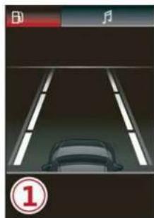
natural_image
Top-down view of a car on a road with lane markings and a play button (no readable text or symbols)
natural_image
Interior view of a car driving on a multi-lane road with lane markings and a vehicle ahead (no visible text or symbols)
Fig. 115 Instrument cluster: driver assistance display
Switching the lane departure warning on and off
The lane departure warning switches on automatically once the ignition is switched on 1).
▶ To switch the system on or off, press the button fig. 114. The respective indicator light in the instrument cluster will turn off or on.
Display and warning
The availability and readiness to provide warnings will be indicated with the / / / / / indicator lights. You can also open the Driver assistance display in the on-board computer → page 15. The display matches the functions of the indicator lights.
① White lines: the lane departure warning is switched on but not ready to provide warnings.
② Green line: the lane departure warning is ready to provide warnings on the respective side.
③ Corrective steering will be indicated with /. If the lane departure warning must intervene for a long period of time, a message will request the driver to drive in the center of the lane. The steering wheel can also vibrate to warn you if lane boundaries are detected during a passing maneuver.
The lane departure warning is ready to provide warnings if an object is detected on at least one side of the individual lane.
If the indicator light turns on, the lane departure warning is not ready to provide warnings. This may be due to the following reasons:
- The necessary lane marker lines have not been detected (for example, in a construction zone or because the lines are obstructed by snow, dirt, water, or lighting)
– The speed is below the activation speed
– The lane is too narrow or too wide
– The curve is too narrow - The driver's hands are not on the steering wheel
– Visibility is obstructed by a rise or dip.
Steering intervention request
If no steering activity is detected or the steering power from the system is not sufficient, the driver steering intervention request will alert the driver using audio and visual signals. Take over the steering and keep your hands on the steering wheel so that you will be ready to steer at any time. The system will become inactive after a short time and will only be active again later.
If the driver does not take over steering, the lane departure warning will no longer be ready to provide warnings. If the vehicle is equipped with emergency assist and it is ready to function, it will be activated page 155.
Behavior when a turn signal is active
Applies to: vehicles with side assist: Even if the system is ready to provide warnings, it will not warn you if you activate a turn signal before crossing the lane marker line. In this case, it assumes that you are changing lanes intentionally.
Applies to: vehicles with side assist: If the turn signal is activated, the lane departure warning is ready, and a lane change has been classified as critical by the lane departure warning due to vehicles traveling beside you or due to approaching vehicles, then a noticeable corrective steering movement will occur shortly before exiting the lane. This will attempt to keep your vehicle in the lane.

WARNING
- Follow the safety precautions and note the limits of the assist systems, sensors, and cameras page 119.
- The system warns the driver that the vehicle is leaving the lane using corrective steering. The driver is always responsible for keeping the vehicle within the lane.
- Corrective steering may not occur at all in certain situations, such as during heavy braking. Always be ready to intervene.

Tips
- Always keep your hands on the steering wheel so you can be ready to steer at any time. The driver is always responsible for
adhering to the regulations applicable in the country where the vehicle is being operated.
- The system does not provide any corrective steering or steering wheel vibrations if it detects that you are passing another vehicle.
Adjusting the lane departure warning
Applies to: vehicles with lane departure warning
You can switch the optional steering wheel vibration warning for the lane departure warning on and off. The settings depend on the vehicle equipment.
- Applies to: MMI: Select on the home screen: VEHICLE > Driver assistance > (💡) > Lane departure warning > Vibration warning.

Tips
Certain settings are stored automatically in the active personal profile.
Messages
Applies to: vehicles with lane departure warning
If 📄 or 📄 is displayed when there is a malfunction, the lane departure warning and lane guidance functions of the adaptive cruise functions may be unavailable or limited.
A message that indicates the cause and possible solution may appear with some displays. The weather conditions may be too poor or the camera may be covered. Clean the area in front of the camera page 121 and try to turn on the systems again later.
If the malfunction remains, drive to an authorized Audi dealer or authorized Audi Service Facility immediately to have the malfunction corrected.
Audi pre sense
Introduction
Applies to: vehicles with Audi pre sense
Within the limits of the system, the Audi pre sense functions can initiate measures in certain driving situations to protect the vehicle
occupants and other road users. Depending on the vehicle equipment, various Audi pre sense systems may be installed:
- Audi pre sense basic can react during emergency and dangerous braking maneuvers and unstable driving situations (such as oversteering or understeering).
– Audi pre sense front 1) can detect an impending frontal impact and react with warnings, braking interventions, and preemptive safety measures for the vehicle occupants.
– Audi pre sense rear monitors the rear traffic behind your vehicle and can react to an impending rear impact.
– Audi pre sense side can detect an impending side impact from cross-traffic and vehicles coming from the side, and can initiate preemptive safety measures. - The swerve assist can assist during an evasive maneuver recognized as critical with steering movement and by braking individual wheels individually.
- The turn assist can detect vehicles in the opposite lane and react with braking maneuvers.
Audi pre sense preemptive safety measures
Applies to: vehicles with Audi pre sense
Depending on the vehicle speed and the vehicle equipment, the following functions may be initiated in certain situations:
– Visual and audio warnings
- Activation of the emergency flashers 1)
– Reversible tensioning of safety belts
– Closing the windows and panoramic glass roof
- Adjusting the seats
- Other preemptive safety measures by individual systems

WARNING
Follow the safety precautions and note the limits of the assist systems, sensors, and cameras page 119.

Tips
- Depending on the risk situation that is detected and the selected Audi drive select* mode, not all preemptive safety measures may be initiated under certain circumstances. Certain functions can be adjusted or skipped if necessary.
- Audi pre sense may be restricted or unavailable under certain circumstances, for example if:
– There are passengers with unfastened safety belts - It has only been several seconds since the ignition was switched on The 📋 indicator light turns on.
- When driving in reverse
– There is an airbag control module malfunction
– System functions may not be available if the ESC is limited or switched off, or if there is a malfunction.
Audi pre sense basic
Applies to: vehicles with Audi pre sense basic
Audi pre sense basic is automatically active at speeds of approximately 20 mph (30 km/h) and higher. Audi pre sense basic can trigger the Audi pre sense preemptive safety measures during emergency braking and dangerous braking maneuvers as well as in unstable driving situations, such as oversteering or understeering.

WARNING
Follow the safety precautions and note the limits of the assist systems, sensors, and cameras page 119.
Audi pre sense front
Applies to: vehicles with Audi pre sense front
The Audi pre sense front uses the data from the camera and calculates the probability of a rear-end collision. Within the limits of the system, an impending frontal impact with vehicles,
pedestrians 1) , or cyclists 1) may be detected in both urban and rural speed ranges.
Audi pre sense front is active at speeds of approximately 6 mph (10 km/h) and higher. It can react to pedestrians 1) or cyclists 1) at speeds up to approximately 50 mph (85 km/h), and can react to vehicles at speeds up to approximately 155 mph (250 km/h).
Early warning/acute warning
The system can recognize various dangerous situations. The early warning occurs if:
– A vehicle driving ahead brakes suddenly
- Your own vehicle approaches a vehicle in front of you that is traveling at a significantly slower speed or that is stationary
- A pedestrian or cyclist 1) is standing in the lane or is moving into the lane
The message Audi pre sense 🕒 and a warning tone will warn you about the danger.
The brakes may also be applied as an acute warning when there is an impending collision. You will also be warned by an indicator in the instrument cluster display. When this warning occurs, it may only be possible to avoid a collision by swerving or braking strongly.
Automatic deceleration
If you do not react to the acute warning, Audi pre sense front can brake the vehicle to a full stop within the limits of the system 1). This reduces the vehicle speed in the event of a collision.
Automatic braking force increase
If Audi pre sense determines that you are not braking strongly enough when a collision is imminent, it can increase the braking force based on the situation.
Take-over
If the message Ⓔ Please take over! appears, the vehicle has been braked to a stop by Audi pre sense and you must resume control of the vehicle.

WARNING
– Follow the safety precautions and note the limits of the assist systems, sensors, and cameras page 119.
- Audi pre sense front cannot overcome natural physical laws. It is a system designed to assist and it cannot prevent a collision in every circumstance. The driver must always intervene. The driver is always responsible for braking at the correct time. Do not let the increased safety provided tempt you into taking risks. This could increase your risk of a collision.
– Audi pre sense front does not react to certain objects, such as animals, crossing or on-coming vehicles, bars, railings, or railcars.
– Audi pre sense front may be limited or unavailable when driving in curves.
- Loose objects can be thrown around the vehicle interior during sudden driving or braking maneuvers, which increases the risk of an accident. Store objects securely while driving.
- In trailer mode, the braking behavior of the trailer can be different than usual during automatic braking.

Tips
Certain pre sense front functions are switched off when the hill descent assist is actively controlling the vehicle.
Audi pre sense rear
Applies to: vehicles with Audi pre sense rear
Within the limits of the system, Audi pre sense rear uses data from radar sensors in the rear area of the vehicle and calculates the probability of a rear-end collision with the vehicle behind you.
Audi pre sense preemptive safety measures can be initiated if the risk of a collision with the vehicle behind you is detected.

WARNING
- Follow the safety precautions and note the limits of the assist systems, sensors, and cameras page 119.
– Audi pre sense rear does not react to pedestrians, animals, crossing objects, and objects not detected as vehicles.

Tips
- Audi pre sense rear functions switch off when trailer mode is detected. There is no guarantee the functions will switch off when using a retrofitted trailer hitch.
– Audi pre sense rear functions may also switch off if there is a malfunction in the side assist system.
Audi pre sense side
Applies to: vehicles with Audi pre sense side
Audi pre sense side uses data from the extra radar sensors installed in the front and rear areas of the vehicle, and other sensors can react to side impacts from cross-traffic and vehicles coming from the side.
Audi pre sense side is active at speeds up to approximately 35 mph (60 km/h). The Audi pre sense preemptive safety measures can be triggered when a collision risk is detected.

WARNING
– Follow the safety precautions and note the limits of the assist systems, sensors, and cameras page 119.
– Audi pre sense side does not react to pedestrians, animals, and objects not detected as vehicles.

Tips
- The Audi pre sense side functions are limited when trailer mode is detected.
- The Audi pre sense side functions may also switch off if there is a malfunction in the intersection assistant*.
Swerve assist
Applies to: vehicles with swerve assist
The swerve assist can help you to steer the vehicle around an obstacle detected in a critical area. If you avoid an obstacle after the acute warning, then swerve assist assists you by specifically braking individual wheels and applying slight steering adjustment to correct the steering wheel angle as long as you are actively steering. The swerve assist is available at speeds between approximately 20 mph and 90 mph (30 km/h - 150 km/h) 1) .

WARNING
- Follow the safety precautions and note the limits of the assist systems, sensors, and cameras page 119.
- Swerve assist does not react to pedestrians, animals, crossing objects, and objects not detected as vehicles.

Tips
– System functions may not be available if the ESC is limited or switched off, or if there is a malfunction.
- An indicator in the instrument cluster will inform you when there is an intervention.
Turn assist
Applies to: vehicles with turn assist
When your vehicle is turning
The turn assist can assist you with a braking intervention when starting to drive or when driving slowly, to reduce the risk of your vehicle colliding with an oncoming vehicle when you are making a left turn. The braking intervention causes your vehicle to stay in its lane. The function is only
available when the turn signal is turned on and at speeds up to maximum of 6 mph (10 km/h).

WARNING
- Follow the safety precautions and note the limits of the assist systems, sensors, and cameras page 119.
- The turn assist does not react to pedestrians, animals, crossing objects, and objects not detected as vehicles.

Tips
- System functions may not be available if the ESC is limited or switched off, or if there is a malfunction.
- An indicator in the instrument cluster will inform you when there is an intervention.
Adjusting Audi pre sense
Applies to: vehicles with Audi pre sense
The system can be switched on and off in the MMI page 122.
You can adjust the Audi pre sense functions to your preferences. The settings depend on the vehicle equipment.
▶ Applies to MMI: Select on the home screen: VEHICLE > Driver assistance > (💡) > Audi pre sense.
Possible settings:
- Turn assist
- Swerve assist
Prewarning 1) - The prewarning can be switched off or the Audi pre sense warning time can be set (Early/Medium/Late).
Set the warning time for the early warning to Early at first. If you feel that the prewarnings appear too early, then set the warning time to Medium. The Late warning time should only be set in special circumstances.

Tips
- Switch Audi pre sense off when you are not using public streets, when loading the vehicle onto a vehicle carrier, train, ship, or other type of transportation, or when towing the vehicle. This can help to prevent an undesired intervention from the Audi pre sense system.
- If the system is switched off, it switches on again automatically once the ignition is switched on again 1) .
- Certain settings are stored automatically in the active personal profile.
Messages
Applies to: vehicles with Audi pre sense
If 🙏 or 🚫 is displayed when there is a malfunction, the Audi pre sense functions may be unavailable or may be limited.
A message that indicates the cause and possible solution may appear with some displays. The weather conditions may be too poor or a sensor may be covered. Clean the area in front of the sensors page 121 and try to turn on the systems again later.
If the malfunction remains, drive to an authorized Audi dealer or authorized Audi Service Facility immediately to have the malfunction corrected.
Side assist
Description
Applies to: vehicles with side assist
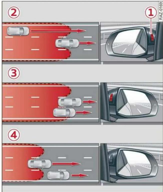
flowchart
graph TD
    A["②"] --> B["①"]
    B --> C["③"]
    C --> D["④"]
    D --> E["①"]
    style A fill:#f9f,stroke:#333
    style B fill:#ccf,stroke:#333
    style C fill:#cfc,stroke:#333
    style D fill:#fcc,stroke:#333
    style E fill:#ffc,stroke:#333
Fig. 116 Diagram: driving situations and displays in the exterior mirror (example)
General information
Side assist monitors the blind spot and traffic in the adjacent lanes behind the vehicle. Within system limits, side assist can detect traffic that is approaching from behind and provide a warning when you are changing lanes and turning. The system uses the data from the radar sensors at the rear corners of the vehicle.
The side assist is active at walking speeds and higher. If an object that is classified as critical is approaching, the display in the exterior mirror ① on the corresponding side of the vehicle will light up.
Driving situations
The system can provide warnings about the following risks:
② Approaching vehicles: a vehicle may be classified as critical in some cases, even if it is farther away. The faster a vehicle approaches, the sooner the display will turn on.
③ Vehicles traveling in the same direction: the display will turn on if vehicles traveling in the same direction as your vehicle are classified as critical. The side assist warns you of all detected vehicles when they are in the “blind spot” or before they reach that point.
④ Vehicles you are passing: the display only turns on if you slowly pass a detected vehicle (difference in speed between the two vehicles is less than 9 mph (15 km/h)). There is no display if you pass a vehicle more quickly.
Information stage
At the information level, the side assist informs you of detected objects that are classified as critical. This is even possible when your vehicle is stationary and the turn signal is turned on, so that the system can also assist you when turning. From speeds of approximately 6 mph (10 km/h) and higher, the system will warn you of detected objects that are classified as critical, even if the turn signal is not turned on.
The display remains dim in the information stage so that you are not distracted while looking forward.
Warning stage
If you activate a turn signal and the display flashes, side assist is warning about objects that have been classified as critical.
Depending on the vehicle equipment and other driver assistance systems, the display may also flash if you have not activated a turn signal. If you are approaching a detected lane marker line and it appears you will be leaving the lane, the display will warn you about detected vehicles that are classified as critical. You can also be warned with corrective steering page 145, Lane departure warning.
Detection range
The radar sensors are designed to detect the left and right adjacent lanes when the road lanes are the normal width. In some situations, the display may turn on even though there is no vehicle located in the area that is critical for a lane change. For example:
- If the lanes are narrow or if you are driving on the edge of your lane. If this is the case, the system may have detected a vehicle in another lane that is not adjacent to your current lane.
- If you are driving through a curve. Side assist may react to a vehicle that is in the same lane or one lane over from the adjacent lane.
- If side assist reacts to other objects (such as roadside structures like guard rails).

WARNING
- Follow the safety precautions and note the limits of the assist systems, sensors, and cameras page 119.
- The display may not appear on time when vehicles are approaching or being passed very quickly.

Tips
- If the window glass in the driver's door or front passenger's door has been tinted, the display in the exterior mirror may be incorrect.
- These systems are not available in trailer towing mode. There is no guarantee the systems will switch off when using a retrofitted trailer hitch. Do not use these functions when towing a trailer.
- For an explanation on conformity with the FCC regulations in the United States and the Industry Canada regulations, see page 300.
Adjusting side assist
Applies to: vehicles with side assist
The system can be switched on and off in the MMI page 122. If the system is activated, the displays will turn on briefly when the ignition is switched on.
Adjusting the brightness
You can adjust the brightness of the display in the exterior mirror. The settings depend on the vehicle equipment.
▶ Applies to: MMI: Select on the home screen: VEHICLE > Driver assistance > (💡) > Side assist > Brightness.
The display brightness is automatically adapted to the ambient light. If the automatic adaptation has already reached the upper or lower limit, no change will be apparent when the setting is changed, or it will only become visible when the ambient light changes. Adjust the brightness to a level where the display in the information stage will not disrupt your view ahead. If you change the brightness, the display will briefly show the brightness level in the information stage.
Messages
Applies to: vehicles with side assist
If 1(3) or 2(3) is displayed when there is a malfunction, the side assist and exit warning system functions may be unavailable or may be limited.
A message that indicates the cause and possible solution may appear with some displays. The weather conditions may be too poor or a sensor may be covered. Clean the sensor area in the vehicle rear and try to turn the systems on again later.
If the malfunction remains, drive to an authorized Audi dealer or authorized Audi Service Facility immediately to have the malfunction corrected.
Exit warning
Description
Applies to: vehicles with exit warning system

Fig. 117 Diagram: approaching traffic detected

Fig. 118 Front door: warning strip (diagram)
General information
Within system limits, the exit warning system can detect traffic approaching from behind such as vehicles, and provide assistance based on this information when you are exiting the vehicle fig. 117. The system uses the data from the radar sensors at the rear corners of the vehicle.
Displays and warnings
If you pull a door handle while the vehicle is stationary and an object classified as critical is approaching, the warning strip ① and the display on the exterior mirror ② will light up on the corresponding side of the vehicle. The opening of the door will also be slowed briefly.
If the door is opened, the displays on that side will flash. If another road user that is classified as critical is approaching while a door is already open, the displays on that door will turn on.
The same messages apply for the exit warning system and side assist page 152.
Switching the exit warning on and off
- The system can be switched on and off in the MMI page 122.

WARNING
- Follow the safety precautions and note the limits of the assist systems, sensors, and cameras page 119.
- Always pay attention to traffic and to the area around your vehicle. The exit warning system does not replace the attention of the vehicle occupants. The vehicle occupants are always responsible for opening the doors and exiting the vehicle.
- The exit warning system does not respond to people and cannot warn you about every type of approaching objects, such as cyclists. Always monitor the traffic as well as the vehicle's surroundings with direct eye contact.
- The display may not appear in time when vehicles are approaching very quickly.
- The exit warning system does not react to stationary objects or pedestrians.
- The exit warning system will not provide alerts if your vehicle is pulled too far into the parking space so that it is hidden by adjacent vehicles.

Tips
- The exit warning system can be available for up to approximately three minutes after unlocking the vehicle and opening the door as well as after switching off the ignition. Then the displays flash briefly and the system switches off.
- The system is not available when towing a trailer. There is no guarantee the system will switch off when using a retrofitted trailer hitch. Do not use these functions when towing a trailer.
- For an explanation on conformity with the FCC regulations in the United States and the Industry Canada regulations, see page 300.
Intersection assistant
Description
Applies to: vehicles with intersection assistant
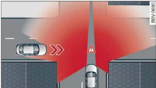
Fig. 119 Diagram: detected cross traffic

Fig. 120 Instrument cluster: directional display from the intersection assistant
General information
The intersection assistant can warn the driver of approaching cross traffic in complex intersections fig. 119.
The system monitors intersections and exit ramps using the sensors installed in the vehicle that detect the front and side areas around the vehicle. Moving objects that are approaching from behind, such as cars, are detected within the limits of the system ▲. The system can also warn the driver of a potential collision with detected approaching cross traffic in intersections and exit ramps with poor visibility.
Requirements for using the intersection assistant:
- The speed must not be higher than approximately 18 mph (30 km/h).
- The "D" gear is selected.
Displays, warnings, and braking
- Display: the red arrow ① can indicate the direction from which the cross traffic is approaching. The indicator in the upper display only appears when the parking aid is activated. For vehicles with peripheral cameras only in the Front and Front corner camera views. The display only appears in the instrument cluster fig. 120 when the Driver assistance display is open in the onboard computer page 15.
- Warnings: the message Cross traffic! can warn you of critical cross traffic when driving forward. There may also be an audible signal.
- Automatic brake activation: if you do not react to a warning, a brief braking by the system can warn you of a potential collision with an approaching object when driving forward at speeds up to approximately 6 mph (10 km/h).
Switching the intersection assistant on and off
- The system can be switched on and off in the MMI page 122.
Messages
If 试, 试 or ✗ is displayed when there is a malfunction, the intersection assistant functions may be unavailable or may be limited.
A message that indicates the cause and possible solution may appear with some displays. The weather conditions may be too poor or a sensor may be covered. Clean the area in front of the sensors page 121 and try to turn on the systems again later.
If the malfunction remains, drive to an authorized Audi dealer or authorized Audi Service Facility immediately to have the malfunction corrected.

WARNING
- Follow the safety precautions and note the limits of the assist systems, sensors, and cameras page 119.
- The intersection assistant will not provide alerts about people and cannot warn you about every type of approaching objects, such as cyclists. Always monitor the traffic
as well as the vehicle's surroundings with direct eye contact.
– The system may not react if vehicles are approaching very fast.

Tips
For an explanation on conformity with the FCC regulations in the United States and the Industry Canada regulations, see page 300.
Emergency assist
Description
Applies to: vehicles with emergency assist
General information
Within the limits of the system, the emergency assist detects if the driver is inactive. In these instances, the system warns the driver, assumes control of the vehicle if necessary, and brings the vehicle automatically to a stop in the lane.
Regardless of the speed, the emergency assist is automatically available when the adaptive cruise assist* is activated. When the adaptive cruise assist* is deactivated, the system is only active at speeds higher than approximately 40 mph (65 km/h).
Emergency assist functions
Within the limits of the system, the emergency assist monitors the driver's steering, accelerator, and brake pedal activity. Depending on the severity of the situation, it may initiate visual, audio, and haptic warnings in stages:
- Reduces the speed
- Messages
– Lowers the volume of the Infotainment system - Audible warning
– Tightening of the safety belt
– A brief application of the brakes
If the driver remains inactive despite the warnings, the emergency assist controls the vehicle within the limits of the system:
- The Audi pre sense preemptive safety measures are triggered page 147.
- The vehicle will stay in the lane and will be braked to a stop.
- As soon as the vehicle comes to a full stop, the emergency flashers are activated and the vehicle prepares for the vehicle passengers to be rescued. The parking brake is set, "P" gear is engaged, the doors are unlocked, and the interior lighting is activated. If there is no movement for several seconds, the emergency call 1) will be made if necessary.
Overriding the emergency assist
You can override the emergency assist ⇒ ⚠:
- Move the steering wheel. Or
- Press the brake pedal. Or
- Press the accelerator pedal distinctly.
When stationary, you can end the emergency assist by leaving the "P" position or releasing the parking brake page 103.
Switching the emergency assist on and off
The system can be switched on and off in the MMI page 122.
Messages
If 📄 or 📄 is displayed when there is a malfunction, the emergency assist functions may be unavailable or may be limited.
A message that indicates the cause and possible solution may appear with some displays. The weather conditions may be too poor or a sensor may be covered. Clean the area in front of the sensors page 121 and try to turn on the systems again later.
If the malfunction remains, drive to an authorized Audi dealer or authorized Audi Service Facility immediately to have the malfunction corrected.

WARNING
- Follow the safety precautions and note the limits of the assist systems, sensors, and cameras page 119.
- The emergency assist is an assist system that should only be used in cases of emergency to take over control of the vehicle and bring it to a stop.

Tips
- Depending on the severity of the detected situation, not all safety measures will be initiated. Certain functions can be adjusted or skipped if necessary.
- If the emergency assist was triggered, it will only be available again after a brief period.
- Certain settings are stored automatically in the active personal profile.
- An indicator in the instrument cluster will inform you when there is an intervention.
Parking and maneuvering
Introduction
Depending on the vehicle equipment, various parking aids will help you when parking and maneuvering.
Parking aid
The parking aid plus assists you while parking by audibly and visually warning you of objects detected in front of and behind the vehicle ⇒ page 157.
The rearview camera shows the area behind the vehicle in the MMI display. The lines in the rearview camera image help you to park and maneuver page 159.
The peripheral cameras are an addition to the rearview camera and help you to see various areas around the vehicle while parking and maneuvering page 159.
The rear cross-traffic assist can warn you of approaching cross traffic when driving in reverse or exiting a parking space page 164.
Settings options
You can adjust parking aid functions individually. The adjustment options depend on the vehicle equipment.
- Activating automatically page 157
- Front and rear volume page 158
- Entertainment fader page 158
– Clean rearview camera → page 160 - Trailer view page 161
- View page 162
– Rear cross-traffic assist page 164

WARNING
Follow the safety precautions and note the limits of the assist systems, sensors, and cameras page 119.

Tips
Practicing parking in a traffic-free location or parking lot to become familiar with the sys-
tems is recommended. Practice parking in good light and weather conditions.
Parking aid plus
Activating/deactivating
Applies to: vehicles with parking aid plus

Fig. 121 Center console: parking aid button
General information
The parking aid assists when parking and maneuvering by providing warnings about obstacles. If the ultrasonic sensors on the vehicle page 120, fig. 91 detect an obstacle, the system will provide audio and visual warnings.
Activating/deactivating
Requirement: the vehicle speed must be under approximately 6 mph (10 km/h).
▶ Press the PA or PB button in the center console. When activating, a brief tone will sound and the LED in the button will turn on.
Automatic activation
The system activates automatically when reverse gear is engaged while the engine is running. A brief tone will sound.
▶ If Automatic activation is switched on in the MMI and if the vehicle approaches) an obstacle at speeds below approximately 6 mph (10 km/h), the parking aid will switch on automatically. Audible signals will sound once the obstacle is within the sensor detection area.
▶ Applies to: MMI: To switch Automatic activation on or off, select on the home screen: VEHICLE > Parking aid > Automatic activation.
Automatic deactivation
The distance indicator for the parking aid plus will deactivate automatically when driving forward faster than 6 mph (10 km/h).

WARNING
Follow the safety precautions and note the limits of the assist systems, sensors, and cameras page 119.

Note
Keep enough distance from the curb to avoid damage to the rims.

Tips
- Certain settings are stored automatically in the active personal profile.
- If the parking aid is deactivated, it can only be reactivated automatically when one of the following conditions is met:
- The vehicle speed exceeds 6 mph (10 km/h)
– The ignition is switched off and back on again - The parking brake is set and then released
- The "P" gear is engaged and released again
Warnings
Applies to: vehicles with parking aid plus

Fig. 122 Upper display: distance indicator
If the sensors detect an obstacle, audible and visual signals will warn you.
Visual warnings
The visual warnings in the upper display help you to detect the critical vehicle area and to estimate the distance to an obstacle.
Red segments ① show detected obstacles that are in your vehicle's path. The red lines ② mark the expected direction of travel based on the steering angle. A white segment ③ indicates a detected obstacle that is outside of the vehicle's path. The closer your vehicle comes to the obstacle, the closer the segments will move to the vehicle. The collision area has been reached when the next to last segment is displayed. Obstacles in the collision area, including those outside of the vehicle's path, are shown in red. Do not continue driving farther.
Audio signals
The closer your vehicle gets to a detected obstacle, the shorter the time between the audible signals. A continuous tone sounds when an obstacle is less than approximately 1 foot (0.30 m) away from the front or rear of the vehicle. Do not continue driving forward or in reverse ⇒ ⚠️.
▶ To deactivate audio signals while parking, press in the upper display. The audio signals will be automatically activated again the next time the parking aid is activated.
Adjusting the volume
You can adjust the volume to your preferences. The settings depend on the vehicle equipment.
▶ Applies to: MMI: Select on the home screen: VEHICLE > Parking aid. Or
▶ Press ☐ in the upper display when the parking aid is active.
Possible settings:
Front volume – Volume for the front area.
Rear volume – Volume for the rear area.
Entertainment fader – The volume of the audio/video source is lowered when the parking aid is activated.
The new level is demonstrated briefly* when the volume is adjusted.
Error messages
If P4 appears, the sensor in the respective area or the speaker is faulty. Drive immediately to an
authorized Audi dealer or authorized Audi Service Facility to have the malfunction repaired.
If 📄 is displayed in the MMI, the ultrasonic sensor indicated is icy or dirty. Clean the area in front of the sensors ⇒ page 121.
If PΔ or PΔ is displayed when there is a malfunction, the parking aid functions may be unavailable or may be limited.
A message that indicates the cause and possible solution may appear with some displays. The weather conditions may be too poor or a sensor may be covered. Clean the area in front of the sensors page 121 and try to turn on the systems again later.
If the malfunction remains, drive to an authorized Audi dealer or authorized Audi Service Facility immediately to have the malfunction corrected.

WARNING
– Follow the safety precautions and note the limits of the assist systems, sensors, and cameras page 119.
- Sensors and cameras have spots in which the surrounding area cannot be detected. Objects, animals, and people may only be detected with limitations may not be detected at all. Always monitor the traffic and the vehicle's surroundings directly and do not become distracted.

Note
Keep enough distance from the curb to avoid damage to the rims.

Tips
– Certain settings are stored automatically in the active personal profile.
- If the distance to an obstacle remains constant, the volume of the distance warning gradually lowers after a few seconds until it is muted (this does not apply to the continuous tone). If the obstacle comes closer than it was before the sound was muted, the tone will sound again. If the obstacle becomes farther away than it was before the
sound was muted, no tone will sound. Pay attention to the vehicle's surroundings when you start to drive.
- There is no rear distance warning when trailer mode is detected. The front sensors remain activated. The visual display switches to trailer mode. There is no guarantee the functions will be deactivated when using a retrofitted trailer hitch.
Rearview camera and peripheral cameras
Introduction
Applies to: vehicles with rearview camera/peripheral cameras

natural_image
Top-down view of three cars parked in a parking lot with a blue arrow indicating direction (no text or symbols)Fig. 123 Orientation line display when parking
Depending on the vehicle equipment, a rearview camera or multiple peripheral cameras may be available.
The rearview camera helps you to park or maneuver using the orientation lines.
The peripheral cameras expand the vehicle overview to include various views around the vehicle that can be selected.

WARNING
Follow the safety precautions and note the limits of the assist systems, sensors, and cameras page 119.
Activating/deactivating
Applies to: vehicles with rearview camera/peripheral cameras

Fig. 124 Center console: parking aid button
Activating/deactivating
▶ Press the MR button in the center console. When activating, a brief tone will sound and the LED in the button will turn on. Or
▶ Press ▶ in the upper display if the visual distance indicator is shown ⇒ page 158, fig. 122.
The system can be activated at low speeds, such when maneuvering.
Automatic activation
The system activates automatically when reverse gear is engaged while the engine is running. A brief tone will sound.
Automatic deactivation
The system will deactivate automatically once the vehicle exceeds a certain speed while driving forward.

WARNING
Follow the safety precautions and note the limits of the assist systems, sensors, and cameras page 119.
Clean rearview camera
Applies to: vehicles with rearview camera/peripheral cameras
You can manually start the cleaning of the rear-view camera. The settings depend on the vehicle equipment.
▶ Select □ > Clean rearview camera in the upper display when the parking aid is active. Or
▶ Move the window wiper lever ⚙ into the position for cleaning the rear window 📋 → page 53.

WARNING
Follow the safety precautions and note the limits of the assist systems, sensors, and cameras page 119.
Warnings
Applies to: vehicles with rearview camera/peripheral cameras

Fig. 125 Upper display: aiming at a parking space
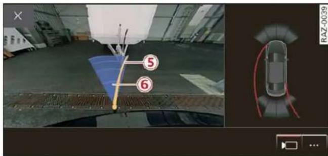
Applies to: vehicles with trailer view
Fig. 126 Upper display: trailer view
When parking with the rearview camera or peripheral camera, the parking aid plus audio and visual warnings* will also assist you page 158.
Visual orientation lines
① The orange orientation lines show the vehicle's direction of travel !. Turn the steering wheel until the orange orientation lines align with the parking space.
② Use the blue markings to help you estimate the distance to an obstacle. Each marking represents approximately 3 feet (1 meter). The blue area represents an extension of the vehicle's outline by approximately 16 feet (5 meters) to the rear.
③ You can recognize the rear bumper in the lower display.
④ You should stop driving in reverse when the red orientation line touches the edge of an object, at the latest.
Trailer view
Applies to: vehicles with trailer view
The trailer view fig. 126 assists you in positioning the vehicle in front of a trailer.
- Applies to: vehicles with peripheral cameras: Switch to the Rear view ⑤ ⇒ page 162, fig. 127.
- Select Trailer view in the upper display when the parking aid is active ☐.
Now you can position your vehicle in front of the trailer. The orange orientation line ⑤ ⇒ fig. 126 indicates the expected path toward the trailer hitch. Use the blue markings ⑥ to help you estimate the distance to the trailer hitch. Each marking represents approximately 1 foot (0.30 meters). The width of the blue surface represents the maximum steering wheel angle.
Symbols
If ☐/☐/☐ is displayed and the display area represented by that symbol is not available, then the camera on the that side is not available. The power exterior mirrors may have been folded in or a door or the luggage compartment lid may have been opened.
If ✗ is displayed, there is a system malfunction and the display area represented by that symbol is not available. The camera is not working in this area.
If 📀 is displayed, the respective ultrasonic sensor is icy or dirty. Clean the area in front of the sensors ⇒ page 121.
If one of the symbols continues to be displayed, drive immediately to an authorized Audi dealer or authorized Audi Service Facility to have the malfunction repaired.

WARNING
- Follow the safety precautions and note the limits of the assist systems, sensors, and cameras page 119.
- Sensors and cameras have spots in which the surrounding area cannot be detected. Objects, animals, and people may only be detected with limitations may not be detected at all. Always monitor the traffic and the vehicle's surroundings directly and do not become distracted.
!
Note
- The orange orientation lines ① show the direction the rear of the vehicle will be traveling, based on the steering wheel angle. The front of the vehicle swings out more than the rear of the vehicle. Maintain plenty of distance so that an exterior mirror or a corner of the vehicle does not collide with any obstacles.
- Keep enough distance from the curb to avoid damage to the rims.
- Only use the images provided by the camera on the rear of the vehicle when the luggage compartment lid is completely closed. Make sure any objects you may have mounted on the luggage compartment lid do not block the rearview camera.
i
Tips
- Applies to: vehicles with air suspension: The accuracy of the orientation lines and blue surfaces on the camera display decreases when the vehicle is raised or lowered with the air suspension.
- There is no rear distance warning when trailer mode is detected. The front sensors remain activated. The visual display switches to trailer mode. The rearview camera image will not show the orientation lines and the blue surfaces. There is no guarantee the functions will be deactivated when using a retrofitted trailer hitch.
Operating the peripheral cameras
Applies to: vehicles with peripheral cameras
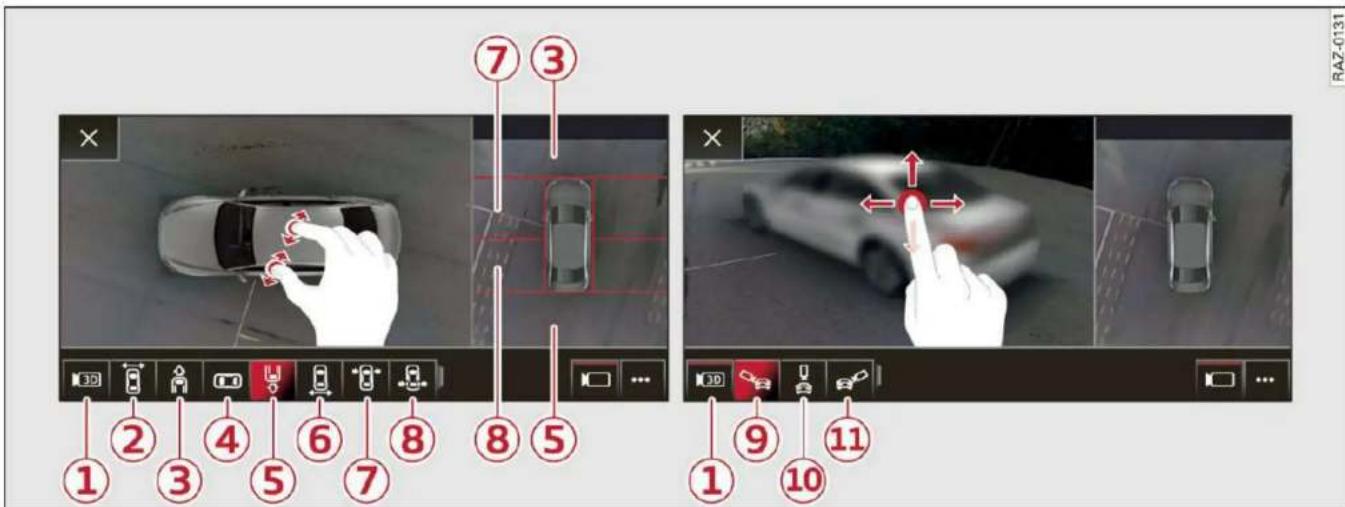
Fig. 127 Upper display: left side: surrounding area. Right side: 3D surroundings.
On vehicles with peripheral cameras, you can select among different views.
The camera views can be controlled with the touch display. In certain views, you can zoom in or out on the displayed area, and move, tilt, or rotate the 3D surroundings.
Selecting the views
▶ To display the entire selection bar, tap the current view ② or swipe at the edge of the selection bar from left to right.
▶ To select a view, press ② - ⑧ in the upper display or tap in an area to show the vehicle in the side view 1).
To select a 3D surroundings view, press the ▶3D symbol ①. Then select the desired 3D surroundings view ⑨ - ⑪.
Switching the views quickly
To switch the views quickly (for example, from Front corner to Front):
▶ Tap the camera image twice. Or
▶ Pull two fingers apart or together in a sideways motion on the camera image.
Zooming in and out on the views
Applies to: surroundings and 3D surroundings views
▶ To zoom in or out on an area, place two fingers on that area and push them apart or pull them together fig. 127, left side.
Moving the view
Applies to: surroundings and 3D surroundings views
▶ To move the view, press and pull it in any direction using one finger.
▶ To re-center the 3D surroundings, tap the camera image twice.
Tilting or rotating the views
Applies to: 3D surroundings view
▶ To tilt or rotate the 3D surroundings, use your finger to drag it in any direction ⇒ fig. 127, on the right side.
▶ To re-center the 3D surroundings behind the vehicle, tap the camera image twice.
Selecting a view in the side area
The vehicle surroundings are shown in the side area of the display. You can switch between a visual display (Graphic) and the vehicle surroundings (Camera).
▶ Select □ > View in the upper display when the parking aid is active.
| Symbol/Description | Description | |
| 1 | 3D | Switch between 3D surroundings and Surroundings |
| 2 | Front corner or display the selection bar | This view makes it easier to drive out of tight parking spaces or areas and intersections with poor visibility. It shows an almost 180° panorama view in front of the vehicle. |
| 3 | Front | This view assists you in using the full area for maneuvering in front of the vehicle. |
| 4 | Surroundings | This view helps you to maneuver and position the vehicle more precisely. The area around the vehicle is shown using the camera images. The vehicle image is shown by the system ⇒ △. |
| 5 | Rear | This view assists you in using the full area for maneuvering behind the vehicle. This is the rearview camera image. |
| 6 | Rear corner | This view can assist you when driving out of tight parking spaces or areas with poor visibility. It shows an almost 180° panorama view behind the vehicle. |
| 7 | Front tires | This view helps you to see the distance between the front tires and the curb and the steering wheel angle when parking. |
| 8 | Rear tires | This view helps you to detect the distance between the rear wheels and the curb when parking. |
| 91011 | 3D surroundings | In these views, you can see the areas surrounding the vehicle in 3D when parking. The vehicle surrounding views are created from the camera images and sensor data. The vehicle image is shown by the system ⇒ △. |

WARNING
- Follow the safety precautions and note the limits of the assist systems, sensors, and cameras page 119.
- The Surroundings and 3D surroundings are created from the individual camera images. The vehicle image is shown by the system. Objects and obstacles above the camera are not displayed.

Note
Only use the images provided by the camera on the rear of the vehicle when the luggage compartment lid is completely closed. Make sure any objects you may have mounted on the luggage compartment lid do not block the rearview camera.
Rear views. If you switch the view manually, the automatic front/rear camera change will be temporarily deactivated.
- When first activated while a forward gear is engaged, the Front corner is displayed.

Tips
- Depending on the selected gear, it will automatically switch between the Front and
Rear cross-traffic assist
Description
Applies to: vehicles with rear cross-traffic assist

Fig. 128 Sensor detection range for rear cross-traffic assist
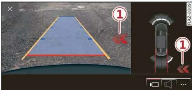
Fig. 129 Upper display: rear cross-traffic assist display
General information
The rear cross-traffic assist monitors the area behind and next to the vehicle using radar sensors at the rear corners of the vehicle. The system can detect moving objects that are approaching, such as vehicles fig. 128. A display in the MMI and various warnings provide assistance when exiting a parking space.
Requirements for using the rear cross-traffic assist:
- Reverse gear must be engaged and the speed while driving in reverse must not be higher than 6 mph (10 km/h).
Displays, warnings, and braking
- Display: the indicator ① in the upper display only appears when the parking aid is activated. In vehicles with peripheral cameras, the display only appears in the Rear and Rear corner camera views. Arrows show the direction from which the cross traffic is approaching.
- Audible warnings: an audio signal may sound as an additional warning when driving in reverse.
- Automatic brake activation: if you do not react to a warning, a brief braking by the system can warn you of a potential collision with an approaching object.
The audible warning signal and the automatic brake activation occur only when driving in reverse.
Switching rear cross-traffic assist on and off
- Applies to MMI: Select on the home screen: VEHICLE > Parking aid > Rear cross-traffic assist. Or
- Select □ > Rear cross-traffic assist in the upper display when the parking aid is active.
Messages
If ☐, ☐ or ✗ is displayed when there is a malfunction, the rear cross traffic assist functions may be unavailable or may be limited.
A message that indicates the cause and possible solution may appear with some displays. The weather conditions may be too poor or a sensor may be covered. Clean the sensor area in the vehicle rear and try to turn the system on again later.
If the malfunction remains, drive to an authorized Audi dealer or authorized Audi Service Facility immediately to have the malfunction corrected.

WARNING
- Follow the safety precautions and note the limits of the assist systems, sensors, and cameras page 119. - The rear cross-traffic assist will not provide alerts about people and cannot warn you about every type of approaching objects, such as cyclists. Always monitor the traffic as well as the vehicle's surroundings with direct eye contact.
- The system may not react if objects are approaching very quickly.
- The rear cross-traffic assist will not provide alerts if your vehicle is parallel parked or if
your vehicle is pulled too far into the parking space so that it is hidden by adjacent vehicles.

Tips
- Certain settings are stored automatically in the active personal profile.
- Once an automatic brake activation occurs, the system cannot initiate another activation for several seconds.
– System functions may not be available if the ESC is limited or switched off, or if there is a malfunction. - If there is an acoustic warning signal from the rear cross-traffic assist, then the parking aid may not warn you of detected obstacles under certain circumstances.
- The system is not available when the vehicle detects that you are towing a trailer. There is no guarantee the functions will be deactivated when using a retrofitted trailer hitch. Do not use these functions when towing a trailer.
- For an explanation on conformity with the FCC regulations in the United States and the Industry Canada regulations, see page 300.
- The coverage areas of the sensors fig. 128 are diagrams and do not represent a true-to-scale image of the sensor ranges.
Telephone
Introduction
Applies to: vehicles with telephone
You can operate various telephone functions easily through the MMI in your vehicle.
Depending on the country and the vehicle equipment, the following options may be available:
- Connecting a cell phone with Bluetooth
- Using two telephones
- Using the Audi phone box

WARNING
- Medical experts warn that mobile devices can interfere with the function of pacemakers. Always maintain a minimum distance of about 7.9 inches (20 cm) between the mobile device antennas and the pacemaker.
- Do not carry the mobile device in a pocket directly over the pacemaker when the phone is switched on.
- Switch the mobile device off immediately if you suspect it may be interfering with the pacemaker.
- Do not use the voice recognition system* page 26 in emergencies because your voice may change in stressful situations. The system may take longer to dial the number or may not be able to dial it at all. Dial the emergency number manually.
- Switch your mobile device off in areas where there is a risk of an explosion. These locations are not always clearly marked. This may include gas stations, fuel and chemical storage facilities or transport vehicles, or locations where fuel vapors (such as propane or gasoline vapor in vehicles or buildings), chemicals or large quantities of dust particles (such as flour, sawdust or metal) may be present in the air. This also applies to all other locations where you would normally turn your vehicle engine off.
- The demands of traffic require your full attention. Always read the chapter page 19, Traffic safety information.

Note
Read the information about Audi connect, and be sure to note the connectivity costs section page 179.

Tips
- The Bluetooth connection range is limited to inside the vehicle.
- A selection of supported Bluetooth devices can be found in the database for tested mobile devices at www.audi.com/bluetooth.
Setup
Connecting a cell phone via Bluetooth
Applies to: vehicles with telephone
Requirement: the vehicle must be stationary and the ignition must be switched on. The Bluetooth settings must be open on your mobile device during the connection setup. The mobile device to be connected must not be actively connected to any other Bluetooth device. The MMI must only be connected to one mobile device.
▶ Enable the Bluetooth function and visibility on the MMI page 227 and the cell phone.
Applies to: MMI: Select on the home screen: PHONE.
▶ Follow the system instructions. The available Bluetooth devices will be displayed after several seconds.
▶ Press on the desired mobile device in the list of displayed Bluetooth devices.
▶ To update the list, press ↻.
A PIN for a secure Bluetooth connection will be generated.
▶ Confirm the PIN on your mobile device, or
▶ Enter the PIN for connecting on your cell phone. The time allowed for entering the PIN is limited to approximately 30 seconds.
▶ Follow the system instructions.
▶ Pay attention to any other system prompts on the MMI and on your cell phone.
After connecting successfully
Information about the connected profiles will appear. You can also change the profiles later ⇒ page 228.
The cell phone contacts are automatically loaded in the MMI. This process can take several minutes, depending on the number of contacts.
Depending on your cell phone and the connection type, you can use the following functions:
Handsfree
Requirement: your cell phone must be connected to the MMI via a Bluetooth Hands Free Profile (Bluetooth HFP).
You can use the hands-free system. You can make calls using the antenna on your mobile device.
Sending and receiving messages
See page 173.

Note
Read the information about Audi connect, and be sure to note the connectivity costs section page 179.

Tips
- You can apply additional settings to connected mobile devices under Connected devices page 227.
- You can also search for the MMI on your mobile device using the Bluetooth device search.
- You only have to pair your device one time. Bluetooth devices that are already paired automatically connect to the MMI when the Bluetooth function is switched on, when they are within range, and when the ignition is switched on. The last connected mobile device is given first priority.
- Pay attention to any system prompts displayed on your mobile device or the MMI, for example if the system should connect automatically in the future. Depending on
the mobile device, you may also need to download contacts and confirm access to your messages separately.
- When leaving the vehicle, the Bluetooth connection to the mobile device will automatically disconnect. Depending on your mobile device, phone calls in progress may be automatically redirected from the MMI to your mobile device so that you can continue the call on your phone.
- When the car phone or data module function* is switched on, Audi connect Infotainment* is available through the embedded SIM card 1)2) .
Using two telephones
Applies to: vehicles with telephone, and Audi phone box
You can connect two mobile devices to the MMI, for example your business and your personal mobile device. You can use both mobile devices to make calls in the vehicle.
Connecting another mobile device
Requirement: a mobile device must be connected to the MMI.
▶ Applies to: MMI: Select on the home screen: PHONE > ☐. Follow the system instructions, or
▶ Applies to: MMI: Select on the home screen: SETTINGS > Connected devices > Telephone 1 or Telephone 2 > New connection.
See → page 166, Connecting a cell phone via Bluetooth.
Switching between two mobile devices
Requirement: phone 1 and phone 2 must be connected to the MMI.
Applies to: MMI: Select on the home screen: PHONE > 📋.
Disconnecting a mobile device
Applies to: vehicles with telephone
The mobile device will be disconnected from the MMI and removed from the list of paired devices.
▶ To disconnect a connected device, use the connection manager page 228.
Using the Audi phone box
Applies to: vehicles with Audi phone box

Fig. 130 Storage compartment under the center armrest: Audi phone box with connections
You can charge your mobile device battery wirelessly using the Audi phone box. You can make calls through the exterior antenna* on the vehicle. Using the external antenna* helps when there is a low signal and also provides better reception quality.
- Position the mobile device in the Audi phone box centered on the symbol ② with the display facing up.
Depending on the vehicle equipment, you may then be able to use the following functions: - Connect to the exterior vehicle antenna 1)
- Wirelessly charge the mobile device. Requirement: the ignition must be switched on. The charging function must be switched on in the MMI. You must have a Qi-capable 2) mobile device.
You can also charge a mobile device using the USB adapter: connect your mobile device to the Audi music interface using a USB adapter cable ①. You can charge your mobile device using specific USB adapters page 215, fig. 148.
Reminder signal
When the device reminder signal is switched on, you will be notified that your mobile device is still in the Audi phone box when you leave the vehicle.
Requirement
- A Qi-capable 2) mobile device must be in the Audi phone box, or
- Your mobile device must be connected to the Audi music interface by a USB adapter, and the Audi smartphone interface must be active, or
- Your iPhone® must be connected to the MMI via Bluetooth® page 166 and must be charging through the Audi music interface using a USB adapter.
Applies to: MMI: Select on the home screen: SETTINGS > General > Reminder signal and mobile device wireless charging.
The following settings are available:
- Signal tone
-Off
- Spoken cue*: this setting is switched on at the factory.
- Mobile device charging notification*: when this function is switched on, the charge status of your mobile device is displayed. You will also be reminded not to forget your mobile device when leaving the vehicle.
- Mobile device wireless charging: when this function is switched on, you can charge your Qicapable mobile device wirelessly in the Audi phone box.

WARNING
- Loose objects can be thrown around the vehicle interior during sudden driving or
braking maneuvers, which increases the risk of an accident. Store objects securely while driving.
- The mobile device may become hot during wireless charging. Pay attention to the temperature of your mobile device and be careful when removing it from the Audi phone box.
- An alternating magnetic field is used for wireless charging. Maintain a minimum distance of approximately 2.4 in (6 cm) to the Audi phone box charging plate. The thresholds for prolonged exposure at this distance comply with ICNIRP1998. Therefore, interactions such as irritation of sensory organs, malfunctions of active implants (such as pacemakers, infusion pumps, or neurostimulators) or effects on passive implants (such as prosthetic limbs) is highly unlikely. If you have an implant, consult a medical specialist if you have any questions. You can also switch the function for wireless charging in the Audi phone box on and off. You can continue to charge your mobile device using a cable connection.
! Note
Applicable to U.S.A.
Operation of the Audi phone box is subject to the following requirements of the Federal Communications Commission:
- This is a CONSUMER device.
- BEFORE USE, you MUST REGISTER THIS DEVICE with your wireless provider and have your provider's consent. Most wireless providers consent to the use of signal boosters. Some providers may not consent to the use of this device on their network. If you are unsure, contact your service provider.
- You MUST operate this device with approved antennas and cables as specified by the manufacturer. Antennas MUST be installed at least 20 cm (8 inches) from any person.
- You MUST cease operating this device immediately if requested by the FCC or a licensed wireless service provider.
- WARNING: E911 location information may not be provided or may be inaccurate for calls served by using this device.
Note
Applicable to Canada
In Canada, operation of a Zone Enhancer, such as an Audi Phone Box, is subject to the following requirements of the Innovation, Science and Economic Development Canada (ISED):
- This is a CONSUMER device.
- BEFORE USE, you MUST meet all requirements set out in CPC-2-1-05.
- You MUST operate this device with approved antennas and cables as specified by the manufacturer. Antennas MUST NOT be installed within 20 cm of any person.
- You MUST cease operating this device immediately if requested by ISED or a licensed wireless service provider.
- WARNING: E911 location information may not be provided or may be inaccurate for calls served by using this device.
i Tips
- Only one mobile device at a time can be charged wirelessly in the Audi phone box.
- Strong transmission quality* cannot be guaranteed if more than one mobile device is in the box.
- To reduce the risk of malfunctions, make sure the mobile device is positioned correctly in the Audi phone box.
- Make sure there are no objects between the Audi phone box and the mobile device.
- Placing the mobile device in a bag or protective sleeve inside the Audi phone box can interfere with the connection to the external antenna*.
- Metallic objects in the Audi phone box block the wireless charging of your mobile device and calls made using the exterior antenna*.
– The maximum charging output is 5 W. -
The charging time and temperature will vary depending on the mobile device being used.
-
You can purchase a USB adapter from an authorized Audi dealer or authorized Audi Service Facility, or at specialty stores.
– Audi recommends using Audi Genuine Accessories. Audi has verified their reliability, safety, and suitability.
Using the telephone
Accessing the telephone functions
Applies to: vehicles with telephone

Fig. 131 Upper display: selection menu
Requirement: a mobile device must be connected to the MMI page 166.
Applies to: MMI: Select on the home screen: PHONE.
The following phone functions will be available:
① Search
② Call list 170
③ Favorites 171
④ Contacts 171
⑤ Voicemail 172
⑥ Dial number 172
⑦ Switching between two mobile devices 176
Selected phone functions are also available in the instrument cluster page 177.
Opening the call list
Applies to: vehicles with telephone

Fig. 132 Upper display: call list
Requirement: the call list must contain a phone number.
▶ Applies to: MMI: Select on the home screen: PHONE > Call list.
Possible call list symbols:
① Missed calls
② Dialed numbers
③ Received calls
④ Edit call list
⑤ Displaying a business card ..... 171
⑥ Number of interactions with a contact
If more than one interaction with a contact has already taken place, the last one is always displayed in the form of an arrow ①, ② or ③.
Press and hold a contact or a phone number in the list until the Options menu appears. Depending on your mobile device, the following options may be available:
- Save as a shortcut page 22, Shortcuts.
- Edit telephone number: edit a phone number before dialing it. Press Dial and start the call.
- Show history*: Requirement: you must have already had more than one interaction with a contact. All interactions with a contact or a number are displayed.
- Store as favorite page 171.
- Send text message page 173.
- Send e-mail page 175.
i Tips
The call list can only be edited via the MMI.
Managing favorites
Applies to: vehicles with telephone
You can store the desired number for a contact as a shortcut in the favorites list.
Accessing favorites
Applies to: MMI: Select on the home screen: PHONE > Favorites.
Storing favorites
▶ Press ☆①⇒page 171, fig. 133 in the business card, or
▶ Press Store as favorite in the options
⇒ page 170.
Deleting favorites
▶ Press ★①⇒ page 171, fig. 133 in the business card, or
▶ Select: Favorites > √≡ > one or more favorites or Select all > Delete > Done.

Tips
If there are multiple mobile devices, you can create separate favorites in the MMI for each mobile device.
Opening contacts
Applies to: vehicles with telephone

Fig. 133 Upper display: business card
You can connect multiple mobile devices to the MMI and manage up to four private phone books in the MMI.
Requirement: a mobile device must be connected to the MMI page 166. You must have at least one contact stored in your mobile device.
Applies to: MMI: Select on the home screen: PHONE > Contacts.
The contacts will be displayed. You can change the sort order page 177, Sort order.
Displaying a business card
The business card shows you details about a contact. To open a business card, press on a contact in the directory.
Possible options in the business card:
① Store/delete as a favorite ..... 171
② Options
③ Call
④ Send text message 173
⑤ Start navigation
⑥ Send e-mail 175
Business card options
Press ⋯②.
Possible options:
- Send contact: you can select Text message or E-mail page 173.
- Add destination: you can add a business or private address page 197, Contacts as navigation destinations.
- Read out name 1) : the MMI automatically creates a name tag that can be read aloud for each entry page 26.
- Save as a shortcut page 22, Shortcuts.
Contact options
Press and hold a contact in the list until the Options menu appears.
Possible options:
- Send contact: you can select Text message or E-mail page 173.
- Send text message page 173.
- Send e-mail page 175.
- Store as favorite page 171.
- Save as a shortcut page 22, Shortcuts.
Deleting contacts
- Deleting all contacts: select: Contacts > Delete all. All contacts are deleted only in the MMI.
- Deleting imported contacts: requirement: you must have imported at least one contact. Select: Contacts > > one or more contacts, or Select all > Delete imported contacts > Done. The imported contacts are deleted.
i
Tips
- Pay attention to any synchronization prompts on your mobile device when downloading contacts.
- Only the contacts of the mobile device being actively used are displayed.
- The contacts from the mobile device may not be transferred in alphabetical order. If there are too many entries, contacts with different first letters may be missing in the MMI.
- If contacts are loaded from the mobile device into the MMI, the contacts on the SIM card will no longer be displayed in the MMI.
- The contacts in the local MMI memory are always visible and can be accessed by other users.
- After switching off the ignition and exiting the vehicle, the mobile device directory will be loaded when the MMI is started again if the mobile device is within range and the Bluetooth function is switched on in the mobile device and the MMI.
- Only the contacts in the local MMI memory can be deleted.
Listening to voicemail
Applies to: vehicles with telephone
Applies to: MMI: Select on the home screen: PHONE > Voicemail.
Requirement: there must be no voicemail number stored.
- Entering the voicemail number: enter the desired number. Press OK.
Requirement: a voicemail number must be stored.
▶ Dialing the voicemail number: press Voicemail. The call begins immediately.
i
Tips
This service must be set up and activated in advance by the cell phone service provider.
Dialing a phone number
Applies to: vehicles with telephone
Depending on the vehicle equipment, you may have the following options for dialing a phone number:
- Using text input in the MMI page 23.
- Using voice operation page 26.
Making an emergency call
Applies to: vehicles with telephone
Requirement: a mobile device must be connected to the MMI via Bluetooth.
▶ Applies to: MMI: Select on the home screen: PHONE > Dial number > the local emergency call number (for example, 911) > Dial.
!
WARNING
- Because your phone works with radio signals, a connection cannot be guaranteed under all circumstances. Do not rely on only your phone when it comes to essential communication (such as a medical emergency).
- Always follow the instructions given by the emergency personnel during an emergency call and only end the call when they instruct you to do so.
Answering/ending a call
Applies to: vehicles with telephone
▶ To accept or end a call, press the Ⓤ button on the multifunction steering wheel. Operating → page 12.
You can use the following options on the MMI when there is an incoming call:
▶ Answering an incoming call: press Answer.
▶ Declining a call: press Decline.
Declining a call with a text message*: Requirement: the function must be enabled in the settings. Press Decline with text message.
▶ Silencing the ringtone: press Mute.

Tips
The radio or media playback is muted during a phone call.
During a phone call
Applies to: vehicles with telephone
The following options may be possible during a call depending on the mobile device being used and the type of connection:
- End call: end the current phone call.
- Mute: the other person on the call will no longer be able to hear you. You will still be able to hear the other person. To switch the microphone back on, press Unmute.
- Hold/Resume: place your current phone call on hold and answer another.
- Send tone sequence: press Numbers. You can enter tone sequences (DTMF) and send them to the other party on the call.
- Accepting an incoming call: if a phone call comes in during another call, you can either Replace the current call with the incoming call, or use Answer to put the current call on hold. The incoming call will be answered.
- Declining an incoming call: press Decline to decline an incoming call.
- Muting the incoming call: press Mute.
- Other call options: press More.
Requirement: two phone calls must be in progress.
– Conference call*: add a call on hold and up to five active parties (depending on the cell phone service provider) to the conference call.
- Swap call: alternate between two phone calls while one of the calls is on hold. Press on the respective call. Selecting End call will end the active phone call. A call that was placed on hold stays on hold and can be taken off hold with Resume.
- Accepting an incoming call: if a phone call comes in during another call and when there is
a call on hold, you can either Replace the current call with the incoming call, or use Answer to put the current call on hold. The incoming call will be answered.
Press More.
- Transferring a call*: press Transfer call to mobile device to transfer the existing call from the MMI to your mobile device or Bluetooth headset*.
- Switch to hands-free mode*: Requirement: you must have a phone call in progress on your cell phone. Press Switch to hands-free to transfer the call from your cell phone back to the MMI.
- Add call: Select: Call list/Contacts/Favorites > select an entry from the list or press Dial phone number and enter a phone number. Then the active call will be on hold.
- Remove conf. member*: Requirement: you must have started a conference call. You can remove conference call members individually when a conference call is active. Press on the contact you would like to remove.
- Microphone input level: you can adjust the microphone input during a phone call using the slider.

Tips
- To be notified of an incoming call during a phone call, the call waiting function in your mobile device must be switched on when using the Handsfree profile.
- When leaving the vehicle, the Bluetooth connection to the mobile device will automatically disconnect. Depending on your mobile device, phone calls in progress may be automatically redirected from the MMI to your mobile device so that you can continue the call on your phone.
Messages
Text messages
Applies to: vehicles with telephone
Depending on the mobile device being used and the mobile network contract, you may be able to receive and send text messages using the MMI.
Requirement: your mobile device must be connected to the MMI via Bluetooth Message Access Profile (Bluetooth MAP) page 166.
▶ Applies to: MMI: Select on the home screen: MESSAGES > (☐) > Text message (SIM card)*/Text message (telephone 1)/Text message (telephone 2)*.
Inboxes
- New text message: press on a template in the list or dictate a text message. Press Add and select one or more recipients from your contacts. To remove a recipient, press Delete. Press Send.
- Inbox: displays all received text messages.
– Sent: displays all sent text messages. - Outbox*: displays all text messages to be sent.
- Drafts*: text messages that have not been sent yet by the mobile device are displayed on the MMI.
- Deleted*: deleted text messages are displayed.
- User-defined*: folders defined by the user are transferred from your mobile device.
Message options
The following options are available when you select a text message:
- Read out* the text message1).
- Reply: a reply can be sent to the selected message in the Inbox.
- To switch to the previous or the next message, press < or >.
- More: options
When you press More, the following options are available:
- Call: Requirement: a number must be stored. You can call the contact.
- Forward: the selected text message can be forwarded to other recipients. Text can also be added before sending.
-
Navigate: Requirement: the contact must have a navigation address stored with it in the directory. You can start route guidance.
-
Extract numbers: Requirement: the message must contain a number. You can extract a number from a text message.
- Send again: Requirement: the text message must be in the Outbox. The selected text message can be resent.
Press and hold an entry in the Inbox until the Options menu appears.
- Reply: a reply can be sent to the selected message in the Inbox.
- Forward: the selected text message can be forwarded to other recipients. Text can also be added before sending.
Settings
Press ⓞ.
- Automatically forward text message to mobile device *2) : when this function is switched on, text messages will also be automatically stored on your mobile device.
- New text message notification: when this function is switched on, you will be notified when new text messages are received. New text messages are indicated with an envelope ☒ in the MMI status bar.
- Text message center*: the number for the text message center of your cell phone service provider is displayed. If no number has been stored yet, you can enter the text message center number.
- Delete text messages from SIM card*: if the memory capacity on the SIM card is full, an envelope with a line through it is displayed in the MMI status bar. You can continue to send text messages, but you cannot receive new text messages. To delete all sent text messages from the SIM card, select All sent messages. To delete all read text messages from the SIM card, select All read messages.
Delete text message
Select: a mailbox > √≡ > one or more text messages > Delete > Done.

Tips
- Please note that you may have to activate the receiving and sending of text messages depending on the SIM card being used (for example, when using a multi-SIM).
- Messages that are deleted in the MMI are also deleted in the mobile device automatically.
- Only new received messages may be displayed depending on your mobile device.
Applies to: vehicles with telephone
Depending on the type of mobile device being used, you may be able to receive and send e-mails through the MMI.
Requirement: your mobile device must be connected to the MMI via Bluetooth Message Access Profile (Bluetooth MAP) page 166.
Applies to: MMI: Select on the home screen: MESSAGES > (✉) > e-mail (phone 1)/e-mail (phone 2)*.
Inboxes
- New e-mail: press on a template in the list. Press Add and select one or more recipients from your contacts. To remove one or all recipients, press Delete. Press Send.
- Inbox: displays all received e-mails. To update the list, press Ⓠ.
– Sent: displays all sent e-mails.
- Outbox: displays all e-mails to be sent.
- Drafts: e-mails that have not been sent yet are displayed.
– Deleted*: deleted e-mails are displayed.
- User-defined*: folders defined by the user are transferred from your mobile device.
Message options
The following options are available when you select an e-mail:
- Read out* the e-mail 1 .
- Reply: a reply can be sent to the selected e-mail in the Inbox.
- To switch to the previous or the next message, press < or >.
- More: options
When you press More, the following options may be displayed depending on your mobile device and the applicable mail folder:
- Call: Requirement: a number must be stored. You can call the contact.
- Forward: the selected e-mail can be forwarded to other recipients. Text can also be added before sending.
- Extract e-mail add.: you can extract the e-mail address from an e-mail.
- Navigate: Requirement: the contact must have a navigation address stored with it in the directory. You can start route guidance.
- Extract numbers: Requirement: the text in the e-mail must contain a number. You can extract a number from an e-mail.
- Show all recipients*: you can display the recipients of an e-mail.
- Show attachmts.*: you can display a list of attachments to an e-mail.
- Send again: the selected e-mail in the Outbox and Sent mailboxes can be sent again.
Press and hold an entry in the Inbox until the Options menu appears.
- Reply: a reply can be sent to the selected e-mail.
- Reply all: a reply can be sent for the selected e-mail and it will be sent to all of the entered recipients.
- Forward: the selected e-mail can be forwarded to different recipients.
Settings
Press Ⓞ.
- New e-mail notification: when this function is switched on, you will be notified when new e-mails are received. New e-mails are indicated with an envelope ☒ in the MMI status bar.
Deleting e-mails
Select: a mailbox > √≡ > one or more e-mails > Delete > Done.

Note
Read the information about Audi connect, and be sure to note the connectivity costs section page 179.
Settings
Phone settings
Applies to: vehicles with telephone
▶ Applies to: MMI: Select on the home screen: PHONE > Ⓞ.
Switching between two mobile devices
Requirement: phone 1 and phone 2 must be connected to the MMI.
Switch telephones: the device name of the available mobile device is displayed. You can switch the phone by pressing the button.
Declining a call with a text message\*
When this function is switched on, you can decline an incoming call with a text message.
Call options\*
The following options may be available depending on the mobile device:
- Call forwarding: you can switch the forwarding of incoming calls to your voicemail or to another phone number on and off. You can check if the function is activated or deactivated with Status.
- Call waiting: you will be alerted to an incoming call during a phone call when the function is switched on. You can check if the function is activated or deactivated with Status.
- Send own number: sending your phone number with an outgoing call can be switched on and off. With the Net.-depen. setting, the setting listed in the contract with the cell phone service provider is used. The settings only apply to the PHONE menu in the MMI. Please note that the settings on your mobile device will apply after disconnecting the Bluetooth connec-
tion. You can determine which setting is active with Status.
Ringtone and volume settings
- Ringtone and message volume: you can adjust the volume of the selected ringtone and the notification volume when a message is received by moving the position of the slider.
- Ringtone*: available ringtones are played using the Ringtone function. Press on an entry in the list.
- Microphone input level: you can adjust the microphone input level using the slider.
Turn on car phone or data module
Applies to: vehicles with car phone/data module
When this function is switched on, you can use the car phone or data module.
As long as the car phone was not turned off separately the last time it was used, it will turn on automatically when the ignition is switched on.
Edit voicemail number
You can change your voicemail number.
Enable VoLTE
When this function is switched on, Voice over LTE* will be supported.
Network settings
- Login to mobile phone network: select to log into your cell phone service provider network automatically or manually.
- Manual network selection: Requirement: the data module must be switched on and Login to mobile phone network must be set to Manual. Select a network manually from the list of available networks at the present location.
Car phone serial number (IMEI):
Applies to: vehicles with car phone
The serial number (IMEI) of your car phone is displayed.

Tips
- Several mobile devices can be paired with the MMI, but only two* mobile devices can be actively connected.
- To delete all paired Bluetooth devices, the Bluetooth function can be reset to the factory default settings page 227.
Directory settings
Applies to: vehicles with telephone
Applies to: MMI: Select on the home screen: PHONE > Contacts >
Switching between two mobile devices
Requirement: telephone 1 and telephone 2 must be connected.
Switch telephones: the device name of the available mobile device is displayed. You can switch the phone by pressing the button.
The directory for the selected phone will be displayed.
Hide grayed-out contacts
When this function is switched on, contacts that have no phone numbers stored for them will be hidden.
Sort order
You can sort the contacts by Last name or First name.
Download contacts
Requirement: a mobile device must be connected to the MMI.
To update the contacts in the MMI, you can manually download your mobile device contacts. Depending on the mobile device, you may need to disconnect and reconnect the Bluetooth connection to update the contacts.
Memory capacity
You can manage up to 23,000 contacts. You can also download up to 5,000 contacts from maximum four mobile devices. You can also import up to 3,000 contacts from a storage medium.
Importing and exporting contacts
Requirement: an SD card must be in the SD card reader* ⇔ page 212 or a USB storage device must be connected to the Audi music interface ⇒ page 215.
Contacts in vCard format (.vcf) can be imported or exported from the MMI.
- Applies to: MMI: Importing contacts from a storage device: Select: Import contacts > Search for import data > SD card 1 or USB device 1/USB device 2 > desired contacts or Select all contacts > Start import.
- Applies to: MMI: Exporting contacts to a storage device: Requirement: Only previously imported contacts can be exported. Select: Export contacts > Find source for exporting > SD card 1 or USB device 1/USB device 2 > desired contacts or Select all contacts > Start export.
i Tips
- For more information about the myAudi account, visit my.audi.com.
- The imported contacts are stored in the local MMI memory.
- Contacts that were downloaded from a mobile device cannot be exported.
– There should be no other files or folders on the storage medium containing the contacts to be imported.
– Apple devices and MTP devices (such as smartphones) are not recognized as USB storage devices.
Mobile phone network settings
Applies to: vehicles with telephone
▶ Applies to: MMI: Select on the home screen: SETTINGS > Connection settings > Mobile phone network.
Switching the car phone or data module on
Applies to: vehicles with car phone/data module
See page 176.
Instrument cluster
Telephone
Applies to: vehicles with multifunction steering wheel and telephone
In the instrument cluster display, you can control the MMI functions with the multifunction
steering wheel. Operating page 12 and page 28, Additional function buttons.
Requirement: the Telephone tab must be selected in the instrument cluster.
▶ Press the ☐ button.
Possible options:
- Call list: Requirement: the call list must contain a phone number.
- Favorites: Requirement: favorites must be stored in the MMI.
- Switch telephones: Requirement: two cell phones must be connected to the MMI.
- Back to call: Requirement: there must be a call in progress.
i Tips
Depending on the selected function, it may be necessary to use the MMI.
Troubleshooting
Applies to: vehicles with telephone
The information that follows lists some trouble-shooting options. They depend on the equipment.
| Problem | Solution |
| Pairing the mobile device to the MMI failed. | Make sure the requirements for connecting a cell phone have been met ⇔ page 166, or make sure you did not accidentally decline the PIN for establishing a connection on your cell phone. If necessary, repeat the pairing process ⇔ page 166. |
| After pairing, not all contacts or no contacts have been loaded into the MMI. | Avoid using special characters in names.Avoid using contact groups on your mobile phone.Check for prompts on your mobile device when connecting via Bluetooth. |
| Certain telephone functions are grayed out or not available. | The telephone functions depend on the mobile device service provider and the mobile device you are using. |
| Some telephone functions may be switched off or not available, even though the mobile device is supported. | Check if the Bluetooth settings on your cell phone are limited or individual Bluetooth settings are deactivated. This may be the case with business cell phones. |
| Wireless cell phone charging is not working or is interrupted. | Check if wireless charging with the Audi phone box is switched on. Check if your mobile device is Qi-capable.Check if your mobile device is positioned correctly in the Audi phone box ⇔ page 168 and no other objects are between them. |
| TheMESSAGES menu is not available. | Check if the Show messages option is on your mobile device and it is enabled. |
Audi connect
General information
Applies to: vehicles with Audi connect
Depending on the country and the vehicle equipment, the following functions may be available:
– Audi connect Infotainment
– Audi connect vehicle control

WARNING
- To reduce the risk of an accident, only use Audi connect services and the Wi-Fi hotspot only if the traffic situation permits it. Read and follow the guidelines provided in page 19, Traffic safety information.
- It is only safe to use tablets, laptops, mobile devices and other similar devices when the vehicle is stationary because, like all loose objects, they could be thrown around the inside of the vehicle in a crash and cause serious injuries. Store these types of devices securely while driving. Also read the warnings in the chapter page 68, General information.

Note
- Applies to: embedded SIM card usage: The connection costs for Audi connect Infotainment services are included in the price of Audi connect Infotainment during the subscription period with some exceptions. Please note that there may be additional charges when using some services. For example, this applies to online radio/podcasts, additional online data, or for Internet connections and services that use the Wi-Fi hotspot, such as online media sources. Depending on the country, data plans may need to be purchased for these services page 184. For additional information, see my.audi.com.
- In certain situations, the Wi-Fi hotspot data connection may be established as a replacement for the SIM card on your Wi-Fi device. This feature depends on the configuration of your Wi-Fi device and operating system. This could result in fees depending on your
cell phone service provider, especially if you are using this feature while abroad. A flat rate data plan is strongly recommended. For more information, contact your cell phone service provider or refer to the owner's manual for your Wi-Fi device.
- You are responsible for all precautions taken for data protection, anti-virus protection, and protection against loss of data on mobile devices that are used, for example, to access the Internet through the Wi-Fi hotspot.
- In areas with poor GPS reception or outside the coverage range of the respective cell phone service provider, some functions and/or services may not be available, it may not be possible to send or receive data, or functionality may be limited.

Tips
– The availability of services depends on the subscription.
– AUDI AG provides access to services from third party providers. Permanent availability cannot be guaranteed, because that depends on the third party provider.
- Use of the most up-to-date mobile network standard is not available in every country. Contact an authorized Audi dealer or authorized Audi Service Facility or your cell phone service provider for additional information.
- Availability, scope, providers, screen display, and costs of services may vary depending on the country, model, model year, end device and rates.
Audi connect Infotainment
Description
Applies to: vehicles with Audi connect Infotainment
With Audi connect Infotainment services, online information is transmitted directly to the vehicle.
An Internet connection is required to use Audi connect Infotainment. Depending on the country
and the vehicle equipment, the following options may be available:
- Embedded SIM card

WARNING
Always follow the information found in in General information on page 179.

Note
Always follow the information found in ! in General information on page 179.
Embedded SIM card
Applies to: vehicles with Audi connect Infotainment and an embedded SIM card
The data connection for Audi connect Infotainment services is made through an embedded SIM card (eSIM card) that is installed in the vehicle. You can use the Audi connect Infotainment services immediately.

Note
Always follow the information found in ! in General information on page 179.
Using a Wi-Fi hotspot
Applies to: vehicles with Wi-Fi hotspot
You can connect up to eight Wi-Fi devices (such as smartphones) with the MMI Wi-Fi hotspot. If the MMI is connected to the Internet ⇒ page 179, the connected Wi-Fi devices can also use the MMI's Internet connection.
Requirement: the ignition must be switched on.
▶ Applies to: MMI: Select on the home screen: SETTINGS > Connection settings > Wi-Fi. Switch on the Wi-Fi hotspot.
- Applies to: MMI: Select on the home screen: SETTINGS > Connection settings > Wi-Fi > Wi-Fi hotspot settings. The access data for the Wi-Fi hotspot is displayed. Switch on the visibility of the Wi-Fi hotspot if necessary. - Switch the Wi-Fi function on in your mobile device and connect it to the MMI Wi-Fi hotspot using the authentication data that is shown.
▶ Follow any additional system prompts on your Wi-Fi device if necessary.
Your device is successfully connected with the MMI's Wi-Fi hotspot.

WARNING
Always follow the information found in in General information on page 179.

Note
Always follow the information found in ! in General information on page 179.

Tips
For an explanation on conformity with the FCC regulations in the United States and the Industry Canada regulations, see page 300.
Audi connect Infotainment services
Configuration
Applies to: vehicles with Audi connect Infotainment
Some Audi connect Infotainment services must be configured through your personal myAudi account at my.audi.com before using them for the first time.

Tips
- For some Audi connect Infotainment services, you may also have to enter your my Audi access information when accessing services in the MMI.
– Some Audi connect Infotainment services must be activated at my.audi.com. - Regardless of the key user and additional users, you can only connect one myAudi account to your vehicle.
- Depending on the country, you may be able to use the myAudi app or my.audi.com.
- For detailed information on configuration, visit my.audi.com.
Services
Applies to: vehicles with Audi connect Infotainment
Depending on the country and the vehicle equipment, the following services may be available:
Weather information
Applies to: MMI
▶ Press WEATHER on the home screen.
Editing settings: select: WEATHER > □□.
Adding a location: select: In a new city > enter the desired location.
▶ To permanently set weather for a location, press on a location.
▶ To always show the weather based on the vehicle position, press on the crosshairs.
Requirement: route guidance must be active.
▶ To show the weather at the destination, press on 📋.
Removing a location: select: > one or more locations or Select all > Delete.
Online news
Applies to: MMI: Select on the home screen: NEWS.
If you logged in to myAudi in your vehicle ⇒ page 29, personalized newsfeeds can be displayed.
Access to Twitter
Requirement: you must have connected your vehicle with myAudi → page 29. You must have connected your myAudi account with Twitter.
You can only connect one Twitter account with your myAudi account. Not all settings can be adjusted in the MMI. Some can only be adjusted through the Twitter website.
▶ Applies to: MMI: Select on the home screen: NEWS > □□. Press on a Twitter entry in the list.
Access to the calendar
Requirement: the myAudi app must be installed and open on your mobile device. Access to your
calendar must be enabled on your mobile device. You must be logged into the myAudi app with your myAudi login data and you must have selected your vehicle. The Wi-Fi function on your mobile device and the MMI must be enabled and your mobile device must be paired to the MMI Wi-Fi hotspot page 180.
You can display the your mobile device calendar on the MMI.
Applies to: MMI: Select on the home screen: CALENDAR.

WARNING
Always follow the information found in in General information on page 179.

Note
Always follow the information found in ! in General information on page 179.
Audi connect vehicle control services
Description
Applies to: vehicles with Audi connect vehicle control
With Audi connect vehicle control services 1), you can utilize various services using the myAudi app or online at my.audi.com.

WARNING
Always follow the information found in in General information on page 179.

Tips
- Accessing specific data or controlling functions remotely depends on the charge level of the vehicle battery. Therefore, these functions only have limited availability after switching off the ignition.
- An eSIM card establishes the Internet connection for Audi connect vehicle control services. The costs for this are included in the price of Audi connect vehicle control
services. The cell phone network, for example, must be available to use these services.
Setup
Applies to: vehicles with Audi connect vehicle control
▶ Register at my.audi.com.
▶ Set the key user page 30.
▶ Install the myAudi app on your mobile device and log in with your access information.

Tips
It may also be necessary to enter your 4-digit PIN set at my.audi.com when accessing some Audi connect vehicle control services.
Services
Applies to: vehicles with Audi connect vehicle control
Depending on the country and the vehicle equipment, the following services may be available:
Locking and unlocking the vehicle by remote control
Requirement: the vehicle must be parked and the ignition must be switched off.
This service allows you to unlock or lock your vehicle.
Vehicle status report
This service transfers driver information system data to a server. Depending on the vehicle equipment, certain data may be accessed, such as the remaining range or mileage. The values may differ from the values displayed in the vehicle.
Car Finder
This service transmits the parking location to a server when the ignition is switched off. The vehicle location, your location, or the route to your vehicle can be displayed. The new parking location cannot be determined with this service if the vehicle is moved after shutting the vehicle off and without switching the ignition on and off again, for example if the vehicle is towed or stolen.
Online Audi service request
Requirement: the service must be activated on-line at my.audi.com and an authorized Audi dealer or authorized Audi service facility must be selected.
This service transmits service-relevant data to your selected authorized Audi dealer or authorized Audi service facility. They will contact you before your next service appointment.
Stolen Vehicle Locator
This service assists you in locating your vehicle if it is stolen.
- Contact the police. You receive a Case ID.
- Call the service hotline and give your Case ID.
The service hotline will forward the established data to the police. You receive the Audi Service hotline number when you purchase your vehicle.
Alert services
Requirement: a key user must be set in the vehicle page 182.
You can adjust the following services in the myAudi app. You will be notified by a push notification and/or e-mail if an alarm is triggered for your vehicle.
– Geofencing Alert: a permitted/prohibited zone was entered.
– Speed Alert: a set speed was exceeded.
– Valet Alert: a set speed was exceeded or a permitted/prohibited zone was entered.

WARNING
Do not ignore messages and warning or indicator lights that turn on in the vehicle because of the information in the vehicle status report. This could lead to break downs in on the road, accidents and serious injuries.

Tips
For some services, you can select if you would like to be notified with a push notification and/or an e-mail.
Settings
Cell phone network
Applies to: MMI: Select on the home screen: SETTINGS > Connection settings > Mobile phone network.
Depending on the country, vehicle equipment, and connection type, the following functions may be available:
Data connection settings
Using the Data connection settings menu, you can set when the system should connect to the Internet. The Internet connection disconnects automatically once the requested Audi connect Infotainment service no longer requires any data.
- Data roaming: data roaming is switched off at the factory. To use a data connection outside of the country, data roaming must be switched on. The setting is stored for the current SIM card or the mobile device that is currently connected.
- Allow MMI online services: when this function is switched on, a data connection is automatically established in order to use Audi connect Infotainment services.
- Allow Wi-Fi devices: when the function is switched on, mobile devices can use the Internet connection through the Wi-Fi hotspot.
Access point
The connection is configured automatically based on the SIM card being used. The following values can be changed. You can obtain more information from your cell phone service provider.
- Access Point Name (APN): the access point depends on the cell phone service provider and is assigned automatically.
- User name: your cell phone service provider assigns the user name for your online profile.
- Password: your cell phone service provider assigns the password for your online profile.
- Apply settings: saves the changed settings.
- Reset configuration: resets the connection settings.
Data usage counter
Your current data usage is displayed.
- Reset counter: you can reset your usage statistics to zero.
- Warning limit: you can set a warning limit for your data usage (GB/MB).

WARNING
Always follow the information found in in General information on page 179.

Note
Always follow the information found in ! in General information on page 179.

Tips
For more information on roaming charges, contact your cell phone service provider.
Wi-Fi settings
Applies to: vehicles with Wi-Fi hotspot
Requirement: the ignition must be switched on.
▶ Applies to: MMI: Select on the home screen: SETTINGS > Connection settings > Wi-Fi.
Depending on the country and the vehicle equipment, the following functions may be available:
Wi-Fi
When the function is switched on, the MMI's Wi-Fi hotspot is active and Wi-Fi devices can be connected to the hotspot.
Wi-Fi hotspot settings
The Wi-Fi connection between the MMI and your Wi-Fi device is encrypted. You can change the following information if needed.
- Access point (SSID): name of the Wi-Fi hotspot.
- Password: a random password was set at the factory in the MMI. The password can be changed. The encryption method requires a password to be at least eight characters long. Choose a secure password.
- Visible to others: you can switch the visibility of the Wi-Fi hotspot on or off.

WARNING
Always follow the information found in in General information on page 179.

Note
Always follow the information found in ! in General information on page 179.
Data plans 1)
Applies to: vehicles with data plans
Requirement: you must have created a myAudi account at my.audi.com. Your vehicle must be registered in your myAudi account.
Troubleshooting
Applies to: vehicles with Audi connect Infotainment
The information that follows lists some trouble-shooting options. They depend on the equipment.
You can purchase data plans at my.audi.com.

WARNING
Always follow the information found in in General information on page 179.

Note
Always follow the information found in ! in General information on page 179.

Tips
Depending on the country, applicable data plans may need to be purchased when driving in other countries.
| Problem | Solution |
| Audi connect Infotainment services: individual Audi connect Info-tainment services are grayed out or not available. | Some Audi connect Infotainment services must be activated or configured through your personal myAudi account before using them for the first time. You can find detailed information online at my.audi.com. |
| Wi-Fi hotspot: it is not possible to connect through Wi-Fi. | Check if Wi-Fi is activated in the MMI ⇒ page 183. Delete all existing Wi-Fi connections on your mobile device and restart it. |
Emergency call
Overview
Applies to: vehicles with emergency call function
An emergency call is a combination of data transmission and a phone call. The data transmission from your vehicle forwards important information, such as the vehicle and position data, to the emergency call center.
Depending on the country and the vehicle equipment, the following functions may be available:
With the emergency call, you can call for help in dangerous situations as quickly as possible. Use this function when emergency help is needed page 185.
– Audi connect emergency call (TPS emergency call). This eCall system uses emergency call centers operated by third party providers.
With online roadside assistance, you can request assistance if there is a breakdown or a minor accident page 186.

WARNING
In areas with poor GPS reception or outside the coverage range of the respective cell phone service provider, some functions and/or services may not be available, it may not be possible to send or receive data, or functionality may be limited.

Tips
To see which data can be transmitted, visit your Audi country or sales region website at www.audi.com.
Emergency call
Operation
Applies to: vehicles with emergency call function
The services are provided through a SIM card installed in the vehicle. Services are provided assuming that the cell phone network required for the installed SIM card is functioning and available for use. The available services set by Audi AG are only available within the cell phone network
coverage area for the cell phone service provider selected by Audi AG.

Tips
– The emergency call function cannot be deactivated in the Infotainment system settings.
– The availability of the TPS emergency call is limited to certain times.
– The costs for call and data connections for TPS emergency calls is included in the price of the services.
Functions
Applies to: vehicles with emergency call function
A TPS emergency call can be made manually or automatically page 185.
Making an emergency call
Applies to: vehicles with emergency call function

Fig. 134 Front headliner: cover for the emergency call button
Manual emergency call
Requirement: the ignition must be switched on.
▶ Tap the cover ① to open it.
▶ Press and hold the emergency call button until the LED ② blinks. The emergency call will be made.
▶ If the emergency call button is pressed by mistake, then press it again immediately and hold it until the LED stays on. The emergency call will be canceled.
Automatic emergency call
The vehicle electrical system initiates an automatic emergency call under certain circumstances, for example if an airbag deploys. The LED in
the emergency call button ② will blink. The emergency call will be made. It cannot be canceled.
LED status
- Green - The emergency call function is available.
- Red - There is a malfunction in the emergency call function. Contact an authorized Audi dealer or authorized Audi Service Facility. Note the messages about the availability of the emergency function page 186.
- Off - The emergency call function is not available, perhaps because no network is available.
Warnings
If there is a critical system failure in the emergency call systems, the vehicle occupants will receive the following warning: see page 186, LED status and page 186, Messages.

Tips
If the emergency call is canceled due to a poor connection, then the system automatically tries to connect again.
Messages
Applies to: vehicles with emergency call function

Emergency call function: malfunction! Re-icted functionality. Please contact Service
If this indicator light turns on and this message appears, the emergency call function is restricted. For example, you cannot call the emergency call center, but data may still be transmitted under certain circumstances. Drive to an authorized Audi dealer or authorized Audi Service Facility immediately to have the malfunction corrected.

Emergency call function: malfunction! Func- n unavailable. Please contact Service
If this indicator light turns on and this message appears, you cannot make an emergency call. Drive to an authorized Audi dealer or authorized
Audi Service Facility immediately to have the malfunction corrected.
Online roadside assistance
Description
Applies to: vehicles with online roadside assistance
An online roadside assistance call 1) is a combination of data transmission and a phone call. The data transmission from your vehicle forwards important information to the Audi service center, such as the vehicle and position data.
Calling online roadside assistance
Applies to: vehicles with online roadside assistance

Fig. 135 Front headliner: online roadside assistance button
Calling online roadside assistance
▶ Press the button ③. The LED in the button turns red. The online roadside assistance call will be made.
▶ If you press the button ③ by mistake, then press it again. Or
▶ Applies to: MMI: Press Cancel or End call.
Audi incident assistance
A minor accident may be detected by the vehicle electrical system. You are able to select between online roadside assistance and an emergency call in the MMI.

Tips
If the roadside assistance call is canceled due to a poor connection, then the call must be made again.
Navigation
Opening navigation
Applies to: vehicles with navigation system
The navigation system directs you to your destination, around traffic incidents, and on alternative routes, if desired.

Fig. 136 Upper display: standard map: route guidance is not started
Opening navigation
▶ Applies to: MMI: Press NAVIGATION on the home screen.
After accessing the navigation for the first time, the map is displayed.
Opening navigation using the multifunction steering wheel
Applies to: multifunction steering wheel: Select the Navigation tab in the instrument cluster.
▶ To display navigation when route guidance has started, select in the instrument cluster: the
button >Map.
The following functions are available in the MMI:
① Open the Select destination menu
⇒ page 189, fig. 137.
② Open intelligent search directly page 189.
③ Switch between the map and the menu: press △ repeatedly until the desired function is displayed.
You can find additional information about the map update at page 195, Map operation.

WARNING
- The demands of traffic require your full attention. Always read the chapter page 19, Traffic safety information.
- The route calculated by the navigation system is a driving recommendation. Follow
the traffic regulations that are applicable in the country where you are operating the vehicle. In the event that the driving directions contradict traffic regulations, always follow the traffic regulations applicable in the country where you are operating the vehicle to reduce the risk of an accident.

Note
Read the information about Audi connect, and be sure to note the connectivity costs section in General information on page 179.

Tips
- Snow and obstructions on the GPS antenna or trees and large buildings can impair satellite reception and affect the system's ability to determine the vehicle position. Several deactivated or malfunctioning satellites can also interrupt GPS reception and affect the system's ability to determine the vehicle position.
– Because street names sometimes change, the names stored in the MMI may in rare cases differ from the actual street name. - Applies to: multifunction steering wheel: Depending on the selected function, operation using the upper display may be required.
- Applies to: vehicles with Audi connect Infotainment: Depending on the country and vehicle equipment, additional services may be available.
- An additional indicator will appear in the head-up display.
myAudi navigation
Applies to: vehicles with Audi connect Infotainment
MMI navigation works seamlessly with the myAudi app.
Your destinations (favorites, last destinations) are synchronized through your myAudi account. All important destinations can be displayed in the vehicle and in the myAudi app.
To download the destinations automatically into the vehicle, we recommend linking the access
data from your myAudi account to your personal profile page 29.
myAudi navigation functions:
- You can send destinations and routes from the myAudi app to the vehicle page 192.
- Active route guidance in the myAudi app can be continued in the MMI.
- Depending on the situation, it may be possible to continue active route guidance from the MMI in the myAudi app to continue navigating to the destination after leaving the vehicle.
! Note
Read the information about Audi connect, and be sure to note the connectivity costs section in General information on page 179.
Entering a destination
Select destination
Applies to: vehicles with navigation system

Fig. 137 Upper display: Select destination menu
Opening a menu
Applies to: MMI
▶ Press NAVIGATION on the home screen.
▶ If the map is displayed, press 品①⇒ page 188, fig. 136.
The following functions are available fig. 137:
① Intelligent search 189
② Entering an address 190
③ Last destinations 190
④ Favorites 191
⑤ POIs 191
⑥ Contacts 192
⑦ Received destinations & routes .. 192
Intelligent search for navigation destinations
Applies to: vehicles with navigation system
Using the intelligent search, you can enter the data for a navigation destination in any order all at once (for example, 5th Avenue New York). You can search for points of interest, contacts, previous destinations, received destinations, and routes or favorites to navigate to the desired destination.
Opening a menu
- Applies to: MMI: Select on the home screen: NAVIGATION > 🔒.
Intelligent search
▶ Enter one or more search terms into the input field. See page 23, Text input.
▶ Press on the desired destination in the results list. The Details menu will be displayed.
▶ Press Start. Route guidance will be activated and the map will be displayed page 194, fig. 139.
If the MMI is connected to the Internet ⇒ page 179, Audi connect, the Intelligent search automatically includes results from the Internet. See ⇒ !.
Change search area
Requirement: route guidance must be active.
Applies to: MMI: Select on the home screen: NAVIGATION > 🔒.
▶ To change the search area, press 📋/ 🔒/ 🔒 → table on page 191 repeatedly until the desired search area is selected.
Online search 1)
Applies to: vehicles with navigation system and online search
You can use the results from a search engine provider to find a navigation destination.
Requirement: the MMI must be connected to the Internet page 179, Audi connect.
Applies to: MMI: Select on the home screen: NAVIGATION > 📞 > G.
▶ Enter one or more search terms into the input field.
▶ The search engine provider shows suggestions 🔗 to narrow down the search.
▶ Press on suggestions until the desired destination appears in the results list. If necessary, use one finger to swipe upward or downward until the suggestions 🔗 or destinations 🔒 appear.
▶ Press on the desired destination 🔒. The Details menu will be displayed.
▶ Press Start.
Route guidance will be activated and the map will be displayed. page 194, fig. 139

Note
Read the information about Audi connect, and be sure to note the connectivity costs section in General information on page 179.

Tips
– The MMI input suggestions depend on the last navigated destinations.
- The navigation system always searches for the fastest route. You can have alternative routes displayed if necessary page 196.
- If the destination cannot be found, it may not be stored in the navigation database. Check the spelling of the term that was searched or check the search area page 189.
Entering an address
Applies to: vehicles with navigation system
As an alternative to the intelligent search, you can also enter an address in stages.
Opening a menu
▶ Applies to: MMI: Select on the home screen: NAVIGATION > (品) > Enter address.
Enter a destination using an address
- Press on the respective input field and enter an address.
▶ Press Apply. The Details menu will be displayed.
▶ Press Start.
Route guidance will be activated and the map will be displayed page 194, fig. 139.
Destination entry for a street intersection
▶ Select: Intersection > enter a street > Start.
Loading previous destinations
Applies to: vehicles with navigation system
Your last destinations and routes can be loaded directly as a navigation destination.
As soon as you start route guidance, the destination is automatically saved in the last destinations. Your previous destinations are marked with the ⏻ symbol.
If you use myAudi navigation, your previous destinations will be synchronized with your myAudi account page 188.
Accessing previous destinations
▶ Applies to: MMI: Select on the home screen: NAVIGATION > (☐) > Last destinations > select a desired destination > Start.
Applies to: multifunction steering wheel: Select in the instrument cluster: Navigation tab > button > Last destinations > desired destination.
Changing and loading a previous destination
▶ Applies to: MMI: Select on the home screen: NAVIGATION > (☐) > Last destinations > ☐ > Change address > Use address > Start.
Restore last tour
Requirement: a route with at least two stopovers must have already been canceled.
Your last route is labeled with the Ⓞ symbol.
▶ Applies to: MMI: Select on the home screen: NAVIGATION > (品) > Last destinations > Restore last tour. Route guidance will start immediately.
Deleting previous destinations
▶ Applies to MMI: Select on the home screen: NAVIGATION > (☐) > Last destinations > ☐ = > one or more entries or Select all > Delete > (Done).
i Tips
The last route will be automatically deleted from the list if you start a new route guidance after canceling the route.
Setting a favorite as the destination
Applies to: vehicles with navigation system
You can access frequent destinations in the favorites. You can quickly and easily start route guidance using the home address or business address function.
Requirement: a favorite must be stored ⇒ page 197.
Applies to: MMI: Select on the home screen: NAVIGATION > (品) > Favorites > select a desired destination > Start. Or
Applies to: multifunction steering wheel: Select in the instrument cluster: Navigation tab > button > Favorites > desired destination.
POIs (Online Points of Interest)
Applies to: vehicles with a navigation system and Audi connect Infotainment
Search for points of interest such as restaurants. If the MMI is connected to the Internet, points of interest will be automatically included in the search.
▶ Applies to: MMI: Select on the home screen: NAVIGATION > (品) > Points of interest.
The system always searches in the search area that is currently selected table on page 191.
- Searching for points of interest: enter the name of a POI.
▶ Searching for a point of interest in a specific category: Select: a category (for example, restaurants) > a point of interest.
▶ Changing the search area: Requirement: route guidance must be active. Press 📁/💡/💡 repeatedly until the desired search area ⇒ table on page 191 is selected.
Sorting points of interest
Requirement: the MMI must be connected to the Internet page 179, Audi connect. You must have a category selected.
▶ Press on the respective symbol for sorting until the desired sorting order is selected.
Search areas in detail
| Symbol | Description |
| [1YH4] | Search nearby |
| [386C] | Search along the route |
 | Search at destination/Search at stopover |
Search nearby: the points of interest will be listed starting from the immediate vicinity around the vehicle position.
Search along the route: points of interest along the route can only be selected during active route guidance. The points of interest are located directly along or in the immediate vicinity of the calculated route. You can select points of interest from various categories. For example, you can search for a hotel or parking lot along route.
Search at destination/Search at stopover: points of interest near a destination or a stopover can only be selected during active route guidance. You can select points of interest from various categories. For example, you can search for a hotel or parking lot at the destination.
Note
Read the information about Audi connect, and be sure to note the connectivity costs section in General information on page 179.
i Tips
Distances to points of interest are displayed as a straight-line distance from your current
location. The actual distance from your current location to the point of interest is updated automatically. The list of points of interest that were found is not resorted when this happens.
Selecting contacts as destinations
Applies to: vehicles with MMI and navigation system
You can navigate directly to contacts.
Requirement: an address with navigation data or a navigation destination must already be assigned to a contact page 197.
▶ Applies to: MMI: Select on the home screen: NAVIGATION > (品) > Contacts > a contact.
▶ Press on an address.
▶ Check the address and change it, if necessary. Start navigation → page 190, Entering an address.
Route guidance will be activated and the map will be displayed page 194, fig. 139.
Additional functions for contacts in navigation can be found under page 197.
i Tips
- Addresses that have been imported from your mobile device into the MMI can also be used as a destination.
- If a contact is grayed out in the directory, this contact has neither a destination nor an address assigned to it.
Loading received destinations and routes
Applies to: vehicles with a navigation system and Audi connect Infotainment
You can search for destinations or routes in the myAudi app and send to the vehicle.
Requirement: the MMI and the mobile device must be connected to the Internet page 179, Audi connect. You must have the myAudi app installed on your mobile device.
- Send a destination or route in the myAudi app to the vehicle.
▶ Applies to: MMI: Select on the home screen: NAVIGATION > (☐) > Received dests. & routes.
▶ Make sure you are logged into the vehicle and the myAudi app with the same myAudi account. The received destination and routes will be loaded automatically.
▶ Navigating to a destination: press on a destination.
▶ Deleting destinations: select: > one or more entries or Select all > Delete > (Done).
Note
Read the information about Audi connect, and be sure to note the connectivity costs section in General information on page 179.
i Tips
To avoid having your enter your myAudi access information in the vehicle again, you can use the automatic login page 29.
Destination details
Applies to: vehicles with navigation system
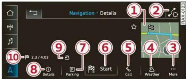
Fig. 138 Upper display: details
After you have selected a destination, the details will be displayed. Route guidance is will not be active yet.
The functions depend on the vehicle equipment and the selected destination.
① Map preview: to zoom in on the map preview, press on the map.
② Route criteria: see page 202.
③ More: see page 201, Options.
④ Weather: Requirement: the MMI must be connected to the Internet ⇒ page 179, Audi connect. Also see ⇒ page 181.
⑤ Applies to: MMI and telephone
Call: Requirement: a mobile device must be connected to the MMI page 166. You will
make a direct call to the phone number that is stored for the destination.
⑥ Start: starts navigation to the displayed destination directly. The map will be displayed page 195, Map operation.
⑦ Parking: press Parking to search for a parking space at the destination. You can use the parking space as the destination or stopover.
⑧ Details: Requirement: the MMI must be connected to the Internet ⇒ page 179, Audi connect.
⑨ Weather at the destination: Requirement: the MMI must be connected to the Internet → page 179, Audi connect.
⑩ Display of distance/driving time to the destination
Note
Read the information about Audi connect, and be sure to note the connectivity costs section in General information on page 179.
Selecting a destination from the map
Applies to: vehicles with navigation system
A point on the map can be used as the destination.
Opening the map
Applies to: MMI
▶ Press NAVIGATION on the home screen.
▶ If necessary, press △ to display the map.
Adjusting the scale
▶ Select: Ⓐ/ Ⓐ > select a scale.
Marking the destination
▶ Press and hold a point on the map until a marking appears 21 ⇒ page 194, fig. 140. Or: the address of the selected destination is displayed 16 ⇒ page 194, fig. 140.
Selecting map content (such as POIs) as the destination
Requirement: map content must be displayed ⇒ page 201.
▶ Press on map content on the map (for example, 22 → page 194, fig. 140).
Selecting the destination
▶ Select: 15 ⇒ page 194, fig. 140. Or:
▶ To display destination details, press on ⑯
⇒ page 194, fig. 140 > Start.
Route guidance will be activated and the map will be displayed page 194, fig. 139.
Stopovers and route plan
Applies to: vehicles with navigation system
You can enter additional destinations during active route guidance.
Entering a stopover
Requirement: route guidance must be active.
▶ Enter a destination page 189.
Displaying stopovers or the route plan
All destinations are listed in the route plan.
▶ Press on ⑦ ⇒ page 194, fig. 139 on the map.
Editing stopovers
▶ Press on ⑦ → page 194, fig. 139 on the map.
- Adding a stopover: Select: Add destination > select a destination > Add.
▶ Moving a stopover: press 🔊. Touch the ◆ symbol and move the entry to the desired position. Press Done.
▶ Deleting a stopover: Select: ⌘ > one or more entries or Select all > Delete > (Done).
Stopping route guidance
Applies to: vehicles with navigation system
Requirement: route guidance must be active and the map must be displayed.
Applies to: MMI: Press ③ → page 194, fig. 139. Or:
- Applies to: multifunction steering wheel: Select in the instrument cluster: Navigation tab > ☐ button > Cancel route guidance.
Map
Map functions
Applies to: vehicles with navigation system
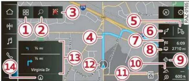
Fig. 139 Upper display: active route guidance
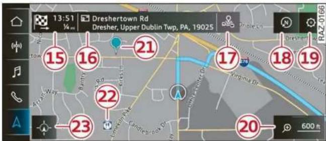
Fig. 140 Upper display: marked map item
Opening the map
Applies to: MMI
▶ Press NAVIGATION on the home screen.
▶ If necessary, press △ to display the map.
The following list gives an overview of the information displayed on the map. Press on any function (for example, alternative routes) to show additional options.
① Destination input page 189
② Intelligent search page 189
③ Cancel route guidance ⇒ page 193
④ Current route
⑤ Request spoken prompt
⑥ Alternative routes page 196
⑦ Display active destinations, stopovers, or route plan. The distance to the destination including the calculated arrival time is displayed page 193.
⑧ For vehicles with trailer mode, the symbol indicates that the function is switched on.
⇒ page 202
⑨ Traffic information ⇒ page 200
⑩ Altitude
⑪ Displays the maximum permitted speed 1) : within city limits, on expressways, and on highways.
⑫ Current vehicle position
⑬ Route information ⇒ page 202
⑭ Name of the street on which you are currently driving
⑮ Start route guidance for the marked destination ⑳ page 193, Selecting a destination from the map
⑯ Display details for the destination
⇒ page 192
⑰ POI search within the vicinity of a marking
⑱ Adjust the map orientation. Also see
⇒ page 201
⑲ Navigation settings → page 201
20 Adjust the scale. Set scale. Or: press the magnifying glass to switch automatic zoom → page 201 on or off directly on the map. The symbol appears when this function is switched on.
21 Marked destination. See page 193, Selecting a destination from the map
②2 Map contents (points of interest, favorites). When there are multiple map contents in the immediate vicinity, the symbols are shown stacked on the map. To display a list of individual symbols, press ⑯⇒ fig. 140. Press on a POI in the list.
23 Center the map to the current vehicle position
Additional possible symbols on the map
| Symbol | Description |
| Home address ⇒ page 197, Favorites | |
| Business address ⇒ page 197, Favorites | |
| Favorites ⇒ page 197 | |
| Previous destinations display |
Traffic information display on the map or map preview
Color-coded markings along the route indicate the traffic flow:
Green: traffic is flowing freely.
Orange: stop-and-go traffic
Red: traffic jam or traffic obstructions.
Shaded markings indicate the length of the area with congestion.
Traffic information
- Colored warning symbols: traffic incidents ahead that are on your route.
- Grayed out warning symbols: traffic incidents that are not on your route.
- All traffic incidents will display in color when route guidance is inactive.
- Warning symbols with arrow: traffic incident that you have been routed around, for example
You can adjust the display of colored markings for traffic information on the maps page 201.
Map operation
Applies to: vehicles with navigation system
You can operate the map page 194, fig. 139 with the movements described in the following information.
Moving the map
- Drag your finger across the map in the desired direction.
Moving the map quickly
▶ Swipe your finger across the map in the desired direction and lift your finger off the map.
Zooming in on the map
- Place two fingers on the map and pull your fingers apart. Or: double tap on the map with one finger.
Zooming out on the map
▶ Place two fingers on the map and pull your fingers together. Or: double tap on the map with two fingers.
Rotating the map
▶ Rotate the map using two fingers.
Tilting the map
- Drag upward or downward with two fingers.
i Tips
Certain gestures may not be available on all touch displays or in every menu.
Navigation view with route guidance started
Applies to: vehicles with navigation system and Audi virtual cockpit

Fig. 141 Instrument cluster: default view: turning maneuver when route guidance has started
Requirement: route guidance must be on ⇒ page 189.
The following information will be displayed in the driver information system, if available:
① Current vehicle position
② A bar graph appears when there is an upcoming turn. The fewer the bars that are shown, the shorter the distance is until the turn. If there is no upcoming turn immediately ahead, the distance to the destination or stopover, the calculated arrival time, and a direction arrow for the upcoming maneuver will be displayed in the right speedometer. If there is no upcoming maneuver, the distance to the next maneuver will be displayed.
③ Lane recommendation
Personal route assistance
Applies to: vehicles with navigation system and personal route assistance
Your MMI can learn the routes that you drive frequently (such as your daily commute to work and back) and suggest route guidance based on the current vehicle position.
When the function is switched on, the MMI records the routes driven regardless of whether or not you are using navigation.
Without starting route guidance, your MMI can check the traffic conditions and shows possible traffic incidents for the possible routes to be driven.
Opening personal routes
Requirement: personal route assistance must be switched on page 202. Route guidance must not be active. A notification is displayed.
▶ The MMI displays up to three suggestions. Press on a suggestion. Route guidance will start.
Better routes
If there are major traffic incidents, the MMI will display a notification regardless of the selected menu. If the MMI has calculated a better route, you can select it as the route.
▶ Press on the notification.
As soon as you switch off personal route assistance, your personal routes will no longer be recorded. Routes that were already stored remain stored.
Deleting personal routes
▶ Applies to: MMI: Select on the home screen: NAVIGATION > ◎ > Personal route assistance > Delete recordings from the last 24 hours or Delete all personal routes and destinations.

Tips
If personal route assistance is switched off and you press 📋, the personal route assistance settings will be displayed → page 202.
Alternative routes
Applies to: vehicles with navigation system

Fig. 142 Upper display: display of alternative routes in the overview map
Opening alternative routes
Requirement: route guidance must be started ⇒ page 189 and the map must be displayed ⇒ page 195.
▶ Press ⑥ ⇒ page 194, fig. 139.
① Move route
You can move the route up to the next destination or stopover.
▶ Press ⚡. The ⚡ symbol will be displayed on the map.
▶ Press and hold 🔍, and use your finger to pull the route to the desired position. Repeat this step until the desired route appears.
▶ Press √.
▶ To cancel, press on the current route ③. Or: press ←.
② Block route
You can block the current route for a certain distance starting from the vehicle position, for example to drive around upcoming streets or tunnel closures. The navigation system automatically calculates an alternative route and the length of the blocked route. The route to be avoided that you have entered applies only to the current route and must be set again, if needed. The areas you have selected to avoid will appear with red and white shading on the map.
▶ Block route: press ② → fig. 142.
▶ Cancel route block: press Ⓧ.
③ Current route
The distance to the destination and the calculated arrival time will be displayed for the current route.
④ Alternative route
As long as traffic information is available, the congestion along the route including the time delay will be displayed. The distance to the destination and the calculated arrival time will be displayed for the alternative route.
Select route
▶ Press on the information window for the applicable alternative route (for example ④ ⇒ fig. 142).
Additional functions
Favorites
Applies to: vehicles with navigation system
You can access frequent destinations in the favorites. You can quickly and easily start route guidance using the home address or business address function.
Accessing favorites
Applies to: MMI: Select on the home screen: NAVIGATION > (品) > Favorites.
If you use myAudi navigation, your favorites will be synchronized with your myAudi account ⇒ page 188.
Storing favorites
▶ Press ☆ in the Details menu ⇒ page 192, fig. 138. Or: press Store as favorite in the options ⇒ page 201.
Storing a home address or business address
- Press Home address or Business address. When accessed for the first time, you will be prompted to set the address. - Select: Create now > enter a destination > OK.
Editing a home address or business address
Requirement: the favorites list must be displayed. Your home address or business address must be stored.
- Press Home address or Business address until the Options menu is displayed. - Select: Change address > enter a destination > (Set as destination) or (Add to address) > OK.
Editing a favorite
Requirement: the favorites list must be displayed. At least one favorite must be stored.
▶ Setting a favorite as a destination: press on a favorite.
▶ Rename favorite: press on a favorite until the Options menu is displayed. Select: Change name > select a name > OK.
▶ Deleting a favorite: press ★ in the Details menu ⇒ page 192, fig. 138. Or: select: ↕≡ > one or more entries or Select all > Delete > (Done).
▶ Moving a favorite: press 🔊. Touch the ◆ symbol and move the entry to the desired position. Press Done.
i Tips
- After deleting the home address or business address, only the address is deleted and the entry will still be displayed in the favorites.
- Please note when moving favorites that items 1 and 2 are reserved for the home address and business address.
Contacts as navigation destinations
Applies to: vehicles with navigation system
Two addresses (private/business) can be added as destinations for each contact. Addresses for contacts on your mobile device are displayed as a mailing address.
Accessing contacts
Applies to: MMI: Select on the home screen: NAVIGATION > (品) > Contacts.
Adding a destination to a contact
Requirement: a mobile device must be connected to the MMI page 166. Or: you must have imported contacts page 177, Importing and exporting contacts. The Hide grayed-out contacts option must be switched off page 198. There must be no business address or private address stored for the desired contact.
▶ Select: a contact > ⋯ > Add destination.
▶ Follow the system instructions.
Settings
▶ Applies to: MMI: Select on the home screen:
NAVIGATION > (☐) > Contacts > Ⓞ.
Hide grayed-out contacts
When the function is switched on, contacts that have no address or navigation destination stored will be hidden in navigation. You can find information for additional settings under page 177, Directory settings.

Tips
If you add a navigation destination to a contact, the destination will only be stored in the MMI. The MMI does not change any contacts on your phone.
On-street parking
Applies to: navigation system and on-street parking
In supported areas, you can display parking along the route.
Requirement: the Parking notification must be switched on page 21, Notification center. The MMI must be connected to the Internet
⇒ page 179, Audi connect. Route guidance must be active, you must be close to your destination, and a notification must be displayed. Or: a point is marked on the map.
▶ Press on the notification. Or: press on ☐ on the map.
▶ To navigate to a parking: space, press on a colored marking on the map.
▶ Select: 📁 > Start.
Depending on availability, colored markings on the map indicate the probability of open parking spaces.
| Color | Description |
| Green | High probability |
| Orange | Medium probability |
| Red | Low probability |

Note
Read the information about Audi connect, and be sure to note the connectivity costs section
⇒ ⚠ in General information on page 179.
Satellite map
Applies to: vehicles with navigation system and satellite map
You can display the navigation map with satellite images.
Requirement: the MMI must be connected to the Internet page 179, Audi connect.
Applies to: MMI: Select on the home screen: NAVIGATION > 🎨 > Map settings > Satellite map 1) .
The map view is based on data packets received from the Internet in the form of satellite images, which are then combined with the roadways from the page 194, fig. 139 standard map view.

Note
Read the information about Audi connect, and be sure to note the connectivity costs section
→! in General information on page 179.

Tips
- The satellite map 1) is updated regularly whenever the function is opened. The process may take several seconds.
- When the satellite map display is switched on 1) with the 3D position map type, the display automatically switches to the 2D map type when driving through tunnels.
- Depending on the Internet connection, the standard map may also be displayed when the satellite map is switched on 1) .
Map update
Introduction
Applies to: vehicles with navigation system
You can update the map data in the MMI with a map update. The functions depend on the country and vehicle equipment:
- Map updates through online map update page 199.
- Import map updates from the SD card or USB connection to your MMI page 199.
- Map update at an authorized Audi dealer or authorized Audi Service Facility. This can result in additional costs.
Online map update
Applies to: vehicles with MMI, navigation system, and Audi connect Infotainment
Using map update online, you can update the map material in your navigation system directly from your vehicle.
Using your vehicle position, the MMI identifies regions which you are frequently in. Based on this, update data for these regions are available for your MMI.
Start map update
Applies to: MMI
Requirement: the MMI must be connected to the Internet page 179, Audi connect.
▶ A notification for a map update will appear in the upper display.
▶ If the option Automatic online map update
⇒ page 200 is switched on, the MMI will start the map update. Or:
▶ Press on the notification. Or: access the notification in the notification center on page 21 and press on the notification.
▶ If the Automatic online map update option → page 200 is switched off, press on Allow once or Always allow.
The MMI will start the map update. The progress of the download and installation will be shown in the upper display.
When the update has ended, a notification will be displayed.
Note
Read the information about Audi connect, and be sure to note the connectivity costs section ! in General information on page 179.
i Tips
Because of the high volume of data, Audi recommends performing the map update using the USB connection page 199.
Map update using an SD card or USB connection
Applies to: vehicles with MMI, navigation system, and Audi connect Infotainment
With the map update, you can update the map material in your navigation system.
Requirement: you must have created a myAudi account at my.audi.com. Your vehicle must be registered in your myAudi account.
Prepare map update
▶ Download the map update at my.audi.com and store it on an SD card or on a USB flash drive. For additional information, visit my.audi.com.
Start map update
▶ Insert the SD card in your vehicle's SD card reader ⇒ page 212. Or: connect the USB flash drive to the Audi music interface ⇒ page 215. A notification for a map update will appear in the upper display.
▶ Press on the notification. Or: access the notification in the notification center on page 21 and press on the notification. The update package is shown.
▶ Press Next. The installation status is shown in the upper display.
- When the update has ended, a notification will be displayed.
Map updates settings
Applies to: vehicles with a navigation system and Audi connect Infotainment
▶ Applies to: MMI: Select on the home screen: SETTINGS > System maintenance.
Automatic online map update: when the function is switched on, map updates will be automatically downloaded and installed.

Note
Read the information about Audi connect, and be sure to note the connectivity costs section in General information on page 179.
Traffic information
Introduction
Applies to: vehicles with navigation system
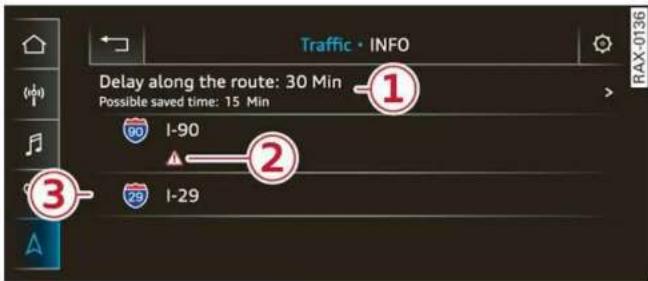
Fig. 143 Upper display: traffic information overview
Open traffic information
Requirement: the map must be displayed ⇒ page 195.
▶ Press ⑨ → page 194, fig. 139.
Display traffic report details
▶ Press on the traffic report ② ⇒ fig. 143.
▶ To display the previous or next traffic report, press ← or →.
The following information can be displayed ⇒ fig. 143:
① A message will appear if the MMI calculates a better route for the current route guidance. More information can be found under page 200.
② A traffic message is displayed. The distance to the hazardous area is calculated from the current vehicle position.
③ The traffic messages are only shown when route guidance is active. Press on a line to display details about it.

Note
Read the information about Audi connect, and be sure to note the connectivity costs section in General information on page 179.

Tips
- Particularly critical traffic information, such as warnings about wrong-way drivers, is automatically displayed as a notification. - Traffic information is not available in some countries.
Better route
Applies to: vehicles with navigation system
By receiving traffic, your MMI calculates a better route if available and the possible time saved compared to the current route. You can decide which route you would like to use.
A notification will appear for several seconds if your MMI calculates a better route for the current route guidance.
A message will also appear in the traffic information overview ① → page 200, fig. 143.
Accept better route
Requirement: a notification about a better route must be displayed.
▶ Press 📋. The better route is used for route guidance and the route is recalculated. Or: press the notification in the central area. The better route with the calculated arrival time is displayed ⇒ page 196, Alternative routes. Press on a better route (for example ④ ⇒ page 196, fig. 142).
Online traffic information
Applies to: vehicles with navigation system and online traffic information
The MMI can receive real-time online traffic information about congestion, accidents, road construction, and other incidents.
Requirement: the MMI must be connected to the Internet page 179, Audi connect. Traffic information must be switched on in the MMI page 201.
Traffic information will be displayed on the standard map page 194, fig. 139.
Online traffic information is also displayed on the standard map page 198.

Note
Read the information about Audi connect, and be sure to note the connectivity costs section in General information on page 179.

Tips
- Having the online traffic information function switched on provides the most accurate reports of traffic situations and traffic forecasting. Your vehicle transmits and processes its anonymous, encrypted position information at regular intervals to the traffic data provider. You can switch off data transfer at any time page 294.
– The online traffic information network is not available in all countries, and the coverage is not nationwide.
Options and settings
Options
Applies to: vehicles with navigation system
Context-specific functions and settings may be available depending on the vehicle equipment.
▶ Press More, or
▶ Open a list with navigation destinations (such as recent destinations) and press and hold an item until the Options menu is displayed.
Storing a favorite
See page 197.
Edit address
You can edit an address for the next destination entry and navigate to the destination. Select: Edit address > enter a street > Use address > Start. If the address is permanently stored (for example, in the favorites), the stored entry will not be changed.
Change address
See page 197, Favorites.
Entering an address
See page 197, Contacts as navigation destinations.
Change name
See page 197, Favorites.
Weather
See page 181, Services.
Save as a shortcut
See page 22, Shortcuts.
Settings
Applies to: vehicles with navigation system
You can adjust the navigation system settings in the instrument cluster and in the MMI display separately. The settings depend on the country and vehicle equipment.
Accessing settings
Applies to: MMI: Select on the home screen: NAVIGATION >
Accessing settings using the multifunction steering wheel
- Applies to: multifunction steering wheel: Select in the instrument cluster: Navigation tab > ☐ button.
Please note that a setting applied to the multifunction steering wheel is only valid for the instrument cluster map.
Map settings
Satellite map: see page 198.
Traffic: you can display current traffic information on the map. See page 195, Traffic information display on the map or map preview
– Free flow of traffic
– Traffic obstructions
– Traffic information
Map colors
- Automatic: the map display adapts to the lighting conditions (for example, by changing from day to night when driving through a tunnel).
- Day or Night
Map orientation
- 2D map or 2D north: the current vehicle position is displayed. The map is oriented in the direction of travel or to the north.
- 3D map: the current vehicle position is shown on a three-dimensional map and is oriented in the direction of travel.
- Overview: the entire route from the vehicle position to the destination or the next stopover is displayed on the map. The map is oriented to the north.
Automatic zoom
- On: the map scale is adapted automatically depending on the type of road being traveled (expressway, highway, other roads) so that you always have an optimal overview of the road ahead. When route guidance is active, the scale is adjusted automatically for a better detailed view when there are upcoming maneuvers.
- Intersection: when route guidance is active, the scale is adjusted automatically for a better detailed view when there are upcoming maneuvers.
-Off
MMI map contents/Map content: you can switch the display of additional information (such as POIs) on the map in the upper display on or off. Note the following for the 3D city model ⚠.
Voice guidance
Voice guidance: you can adjust the navigation prompts. With the Traffic setting, the MMI will only give prompts if there are traffic incidents on your route.
Voice guidance during phone call
Entertainment fader during navigation: the audio playback volume is temporarily lowered when navigation prompts are active.
Route criteria
You can adjust which route criteria should be allowed or avoided for the route calculation.
HOV/carpool lanes
Highways
Toll roads
Ferries
Route information
When this function is switched on and route guidance is active, route information ⑬ ⇒ page 194, fig. 139 is displayed. The next maneuver will be displayed at the bottom. POIs and traffic information will also be displayed. Press route information to display a preview of the next maneuver on the map. You can switch the following information on or off in route information.
- POIs along the route
– Traffic information
Personal route assistance
Personal route assistance is switched off at the factory.
Your trips are recorded and destinations are suggested by the MMI when this function is switched on page 196.
Trailer mode
Trailer mode is switched off at the factory.
When the function is switched on, the maximum permitted speed for vehicles with trailers is included during route guidance and the calculated arrival time is adjusted accordingly. When the function is switched on, the symbol ⑧
→ page 194, fig. 139 is displayed on the map.
Presentation mode
In presentation mode, the system simulates driving along the planned route without the vehicle actually moving. You can use Specify starting point when you would like to calculate a route starting from a location other than the current vehicle position, for example. Simulating route guidance: start route guidance and press Presentation mode.

Note
Read the information about Audi connect, and be sure to note the connectivity costs section in General information on page 179.

Tips
You can adjust the volume of navigation prompts during voice guidance using the On/Off knob page 19. Also see page 226.
Radio
Opening the radio

Fig. 144 Upper display: station list

Fig. 145 Upper display: SiriusXM channel list
Depending on the vehicle equipment, the radio may support the FM, AM, and SiriusXM (satellite radio) frequency bands. Using the HD Radio receiver also allows you to receive radio stations on the FM and AM bands in digital format.
Depending on the station list, the following information may be displayed:
① Station list
Shows the station that is currently playing. The station list updates automatically.
② Stations
Depending on availability, the station name as well as program information, for example, may be displayed.
③ HD Radio technology
FM/AM stations that can be received by digital radio are marked with the HD Radio technology symbol HD).
If reception quality declines, the radio automatically switches to the analog FM/AM station depending on availability.
④ Additional stations
Digital HD Radio stations may contain multiple additional stations. If you lose reception,
the additional stations will be muted since they can no longer be received.
⑤ Radio ID
Your radio ID and contact data for your satellite radio provider are displayed.
⑥ Channel number
⑦ Smart Favorite
See page 207.
Adjusting the radio using the MMI
Applies to: MMI: To set a frequency band, select on the home screen: RADIO > Source > a frequency band.
Applies to: MMI: To set a station, select on the home screen: RADIO > Source > a station list > a station.
▶ To select a frequency, follow the instructions under page 206, Free text search.
Adjusting the radio using the multifunction steering wheel
Requirement: radio mode must be on.
▶ Select the Radio/Media tab using the multifunction steering wheel.
▶ To switch between radio and media, select the button > Switch to radio/Switch to media.
▶ Turn the left thumbwheel to display the station list.
▶ To switch to a different source, press the ☐ button.
▶ To select a station or a source, turn and press the left thumbwheel.
i Tips
- Contact the SiriusXM* provider if you would like to receive satellite programming.
– Buildings, tunnels, bridges, open areas, other vehicles or objects on the vehicle roof can affect reception. - Satellite radio is not available in Alaska and Hawaii.
- Applies to: multifunction steering wheel: Depending on the selected function, operation through the MMI may be required.
Radio functions
Overview

Fig. 146 Upper display: left side: playback view of radio functions, right side: sources
Operating
Applies to: MMI: To open the playback view ①, select on the home screen: RADIO > a radio station.
Applies to: MMI: To open the sources ②, select on the home screen: RADIO > Source.
The following functions may be available depending on the selected radio station and the vehicle equipment:
| Symbol/Description | Description | |
| 3 | Source button | Displays sources in the Radio menu. |
| 4 | Frequency band | Shows the current station frequency band. If a symbol with the WEB label is displayed, then the station is being streamed from online. Always follow the information found in ⇒! . |
| 5 | ☆/★ | See ⇒ page 206. |
| 6 | Settings ⇒ page 210. | |
| 7 | Station logo | Switching between picture views: press the station logo. Use one finger to swipe to the right or left to switch between the Station logo and Cover art.Station logo: the station logo is displayed, depending on availability.Cover art: the album cover is displayed if available. Always follow the information found in ⇒! . |
| 8 | ← | Go back one level. |
| 9 | Search | See ⇒ page 206. |
| 10 | Last stations | Displays the last played stations ⇒ page 206. |
| 11 | Presets | See ⇒ page 206. |
| 12 | SiriusXM station list | Displays stations from the SiriusXM frequency band. |
| 13 | Online | See ⇒ page 208. |
| 14 | AM | Displays stations from the AM frequency band. |
| 15 | FM | Displays stations from the FM frequency band. |
| 16 | SiriusXM alerts | Overview of songs, artists, or teams from the stored SiriusXM alerts being currently received ⇒ page 207. |
| 17 | More | Access options for the current station ⇒ page 209. |
| 18 | K/KN | Select the previous/next station. |
| 19 | OK/OK | Unmutes or mutes playback. |
| 20 | List | The station list is displayed ⇒ page 204. |
| 21 | Info section | Depending on availability, the station name as well as program information, for example, may be displayed. Also see ⇒ page 210, Online additional data. |

Note
Read the information about Audi connect, and be sure to note the connectivity costs section in General information on page 179.

Tips
Not all functions are available in every source and on every touch display.
Free text search
Applies to: vehicles with free text search
Using the free text search, you can select the order that the search terms are entered in the input field. Search in all frequency bands for a station name, channel number, or program type, such as News. You can also select the frequency.
Opening free text search
Applies to: MMI: Select on the home screen: RADIO > Source > Search.
Setting the frequency
- Enter a frequency. - Press on a frequency in the results list.
The following information may be available:
| Symbol | Description |
| Results from the list:Last stations | |
| Results from the list:Presets | |
| Results from aStation list | |
| For example,FM | Station frequency band |
Last stations
Applies to: vehicles with last stations
You can listen to the last stations that were played in all frequency bands.
Accessing last stations
Applies to: MMI: Select on the home screen: RADIO > Source > Last stations.
Listening to last stations
▶ Press on a station.
Deleting last stations
▶ Select: ⌘ > one or more stations or Select all > Delete > (Done).
Presets
Applies to: vehicles with presets
You can store your favorite stations from every frequency band in the presets list.
Selecting presets using the MMI
▶ Applies to: MMI: Select on the home screen: RADIO > Source > Presets > a preset.
Storing presets
▶ Press on ☆⑤⇒page 205, fig. 146 in the play-back view.
Requirement: a list with radio stations must be displayed page 204, fig. 144.
▶ Press and hold an entry in the list until the Options menu appears.
▶ Press Store as preset.
Editing a preset
▶ Deleting a preset: press ★ in the playback view, or
▶ In the presets list, select: ≈ > one or more stations or Select all > Delete > (Done).
Requirement: the presets list must be displayed.
▶ Moving a preset: press 📋.
- Touch the ◆ symbol and move the entry to the desired position.
▶ Press Done.
Smart favorites
Applies to: vehicles with SiriusXM
SiriusXM channels are stored in the presets as smart favorites with the ★ SMART symbol. After switching the ignition and the MMI on, the smart favorites store radio programs at a specific time.
- Press on a smart favorite. You have the following options:
▶ Pause/Start: press II/D.
▶ Selecting the previous or next track: press □□. - Going to the beginning of a recording or live program: press and hold ☐< or >☐.
▶ Setting the playback point: you can adjust the playback position using the knob.
▶ Going to a live program: press LIVE.
Radio text
Program information (for example, general text messages, artist, composer, song) is displayed in the radio text.
Requirement: the selected radio station must support the radio text function.
Opening radio text
Applies to: MMI: Select on the home screen: RADIO > select a frequency band (such as FM) > select a station > More > Radio text.
Displaying previous radio text entries: drag your finger downward. The last radio text entries are displayed if they are available.
Browsing through radio text entries: drag your finger upward or downward on the screen.
If a radio text entry is displayed with a color, a phone number or a navigation destination for the station is available as radio text plus information.
i Tips
The availability of radio text and RadioText Plus depends on the radio station.
SiriusXM alerts
Applies to: vehicles with SiriusXM
You can see an overview of your favorite artists, favorite songs, or teams that are currently being broadcast on a SiriusXM channel.
Accessing SiriusXM alerts
Applies to: MMI: Select on the home screen: RADIO > Source > SiriusXM Alerts.
After you have saved a SiriusXM alert, you can see an overview in the SiriusXM alerts menu of the songs, artists, or teams being currently received and can play them directly from there.
Storing a SiriusXM music alert
Requirement: an artist or song must be playing on a SiriusXM channel.
Applies to: MMI: Select on the home screen: RADIO > Source > SiriusXM > a channel > More > Artist as SXM alert/Title as SXM alert.
Storing a SiriusXM game alert
Applies to: MMI: Select on the home screen: RADIO > Manage SiriusXM alerts > Store SiriusXM alerts > an entry from the list.
Playing a song/artist/team from a SiriusXM alert (option 1)
Requirement: a SiriusXM music/game alert must be stored and must be currently broadcast on a SiriusXM channel.
Applies to: MMI: Select on the home screen: RADIO > Source > SiriusXM Alerts > an entry from the list.
Playing a song/artist/team from a SiriusXM alert (option 2)
Requirement: a SiriusXM music/game alert must have been received.
▶ Press on the notification, or
▶ Open the notification in the notification center on page 21 and press on the notification.
Managing SiriusXM alerts
Requirement: a SiriusXM alert must be stored.
Applies to: MMI: Select on the home screen: RADIO > Manage SiriusXM alerts > Selected SiriusXM music alerts/Selected SiriusXM game alerts.
When the function is switched on ☑, a SiriusXM alert will be received.
Deleting SiriusXM alerts
▶ Select: Selected SiriusXM music alerts/Selected SiriusXM game alerts > ∥≡ > one or more alerts or Select all > Delete > (Done).
Online radio
General information
Applies to: vehicles with Audi connect Infotainment and on-line radio
You can listen to various radio stations or podcasts on the Internet using online radio.
Requirement: the MMI must be connected to the Internet page 179, Audi connect.
Opening online radio using the MMI
Applies to: MMI: Select on the home screen: RADIO > Source > Online.
The following functions are available:
Search
You only can search for online radio stations in this search. You can search for station names and categories.
Last played station
The station that was played last will start playing.
Top stations
Select a station from the list of popular online radio stations.
Filter list
▶ Select: Ⓞ > (a category) > a station name.
The following categories are available:
- Countries
- Genres
– Languages
Note
Read the information about Audi connect, and be sure to note the connectivity costs section in General information on page 179.
i Tips
- Depending on the Internet connection and network traffic, the connection may be lost when online radio is playing.
- Online radio reception may not be possible if Internet service is throttled.
– The use of online radio depends on the service availability of the third party provider.
– The range and screen display of online media services from third party providers in the vehicle can vary.
– AUDI AG only provides access to online radio and does not assume any responsibility for the content of these services.
Podcasts
Applies to: vehicles with Audi connect Infotainment and online radio
Opening podcasts using the MMI
Applies to: MMI: Select on the home screen: RADIO > Source > Online > Podcasts.
The following functions are available:
Listening to a podcast
▶ Select: a podcast > a podcast episode.
Search
▶ Press ⚙.
The following functions are available in the pod-cast playback view:
Displaying podcast episodes
▶ Press List.
Starting/stopping podcast playback
▶ Press ▷/11.
Previous/next podcast
▶ Press ◀/◀.
Changing the playback position
▶ You can adjust the playback position using the knob.
Displaying the online radio menu
▶ Press 品.
Switching to radio
▶ Press Source. The sources in the Radio menu are displayed.
Podcast favorites
You can store podcasts in the Podcast favorites.
Requirement: the playback view for a podcast must be displayed.
▶ Press ☆ ⑤ ⇒ page 205, fig. 146.
Requirement: a list with podcasts must be displayed.
▶ Press and hold an entry in the list until the Options menu appears.
▶ Press Save podcast.
Listening to a podcast favorite
Requirement: the podcast favorites list must be displayed. At least one podcast favorite must be stored.
▶ Press on the desired podcast.
Scrolling through podcast favorites
Requirement: the podcast favorites list must be displayed. At least one podcast favorite must be stored.
▶ Swipe to the left or right with your finger.
Displaying all podcast favorites
Requirement: the podcast favorites list must be displayed. At least one podcast favorite must be stored.
▶ Press All.
Editing podcast favorites
▶ Deleting podcast favorites: press ★ in the playback view, or
▶ In the podcast favorites list, select: All > √≡ > one or more podcasts or Select all > Delete > (Done).
Requirement: the podcast favorites list must be displayed.
▶ Moving a podcast favorite: Select: All >
- Touch the ◆ symbol and move the entry to the desired position.
▶ Press Done.
Options and settings
Options
Requirement: the playback view ① → page 205, fig. 146 must be displayed.
▶ Press More, or
Requirement: a list with radio stations or podcasts* must be displayed page 204, fig. 144.
▶ Press and hold an entry in the list until the Options menu appears.
Depending on the selected source, the following functions may be available.
Storing a preset
See page 206.
Radio text
See → page 207.
Scan
All channels in the current channel list will be played for several seconds each.
Scan smart favorites
All smart favorites will be played for several seconds. The stored song on the smart favorite channel will be played from the beginning page 207. To switch to the previous or next smart favorite, press the On/Off knob briefly to the left or right.
Artist as SXM alert
The artist being currently played will be stored as a SiriusXM alert page 207.
Title as SXM alert
The title being currently played will be stored as a SiriusXM alert page 207.
Team 1 as game alert/Team 2 as game alert
The teams currently playing will be stored as a game alert page 207.
Save podcast
See page 209, Podcast favorites.
Save as a shortcut
See page 22, Shortcuts.
Settings
Applies to: MMI: Select on the home screen: RADIO >
Depending on the vehicle equipment, the following settings may be available:
HD Radio FM/HD Radio AM
You can switch HD Radio reception on or off.
SiriusXM Tune Start
If you play a smart favorite when this function is switched on, the song currently playing on the channel will play from the beginning.
Managing SiriusXM alerts
See page 208.
SiriusXM channel sorting
You can set how the channels are sorted in the SiriusXM channel list:
- Channel number: the channels are sorted in ascending order according to their channel number.
- Channel name: the channels are listed in alphabetical order.
- First category, then channel number: the channels are sorted by their category and then by their channel number.
- First category, then channel name: the channels are sorted by their category and then by their channel names.
SiriusXM category filter
The stations shown in the station list can be filtered by your personal preferences and by program type. The program categories that you can select depend on what is offered by your provider. When the Unsubscribed channels function is switched off, unsubscribed channels will be hidden.
SiriusXM subscription status
This option is available when your subscription is about to expire or has already expired. The expiration date for your license is displayed.
Call SiriusXM: the telephone number and radio ID of your satellite radio provider are displayed. To call your satellite radio provider using the MMI, press Call SiriusXM.
Online additional data
Requirement: the MMI must be connected to the Internet page 179.
When the function is switched on, additional information (such as station logos, cover, artist, track) will be loaded depending on the availability from the different providers.
Preferred online radio data rate
You can set the data rate for online radio ⇒ page 208.
For optimal sound playback, press High. To reduce data usage, press Low.

Note
Read the information about Audi connect, and be sure to note the connectivity costs section in General information on page 179.

Tips
Delays may occur when switching automatically between normal frequency bands and online radio.
Troubleshooting
The information that follows lists some trouble-shooting options. They depend on the equipment.
| Problem | Solution |
| A station is no longer displayed in the station list. | Store the station as a preset in advance. Access the pre-sets using the presets list ⇒ page 206. |
| Online radio: no playback from online radio. | Check if a suitable data plan was purchased ⇒ page 184. |
Media
General information
There may be different media sources and connections available depending on the vehicle equipment. For example, you can play media files using the SD card reader or connect your mobile devices to the Audi music interface and operate them through the MMI.
Media and format restrictions: the MMI (including the SD card reader and the USB storage device connection) was tested with a variety of products and media on the market. However, there may be cases where individual devices or media and audio/video files may not be recognized, may play only with restrictions, or may not play at all.
Restricted functionality: reset the Media to the factory default settings if functionality is restricted page 227.
Digital Rights Management: please note that the audio/video files are subject to copyright protection.
Files that are protected by DRM and are identified with the symbol ☐ will not play.
Data security: never store important data on SD cards, CDs/DVDs, or mobile devices. Audi AG is not responsible for damaged or lost files and media.
Loading times: the more files/folders/playliststhere are on a storage medium, the longer it willtake to load. To reduce the amount of time ittakes the audio/video files to load, use a storagemedium that only contains audio/video files, andcreate subfolders (for example, for each artist oralbum).
Additional information: when playing, audio files are automatically displayed with any additional information that is stored (such as the artist, track and album cover). If this information is not available on the storage medium, the MMI will check the Gracenote metadata database. However, in some cases, the additional information may not be displayed.

Note
Read the information about Audi connect, and be sure to note the connectivity costs section
⇒ ⚠ in General information on page 179.
SD card reader
The SD card reader is in the storage compartment under the front center armrest.
Inserting the SD card
▶ The angled corner of the SD card must face toward the right front side when being inserted.
▶ Slide the SD card into the card reader slot until the SD card clicks into place.
The SD card reader is accessed and operated through the MMI page 216.

Note
- Only use one-piece SD cards. If adapter cards (SD cards with more than one piece) are used, the card could fall out of the adapter when driving because of vibrations. Individual pieces could then become stuck in the drive and impair the functionality.
- To reduce the risk of damaging drives and data carriers, always keep data carriers in a sleeve and never expose them to direct sunlight.
DVD drive
General information
Applies to: vehicles with a DVD drive
The functionality of individual storage mediums may be limited due to the variety of blank CDs/DVDs available and the various capacities. Audio CDs or video DVDs with copy protection, CDs/DVDs that do not conform to the standard, and multisession CDs may have limited playback or may not play at all. AUDI AG recommends finalizing the recording process when creating multisession CDs. Multisession DVDs are not supported.

Note
To reduce the risk of damaging the drive and data carriers:
– Always store data carriers in a protective sleeve and do not expose them to direct sunlight
- Do not use damaged, dirty, or laminated data carriers
- Do not use single CDs/DVDs with a 3.1 inch (8 cm) diameter, non-circular CDs/DVDs (shaped CDs), cleaning CDs, and protective rings
- Never force CDs/DVDs into the drive. Discs are pulled in automatically.

Tips
The thermal protection switch stops playback temporarily when outside temperatures are too high.
DVD drive
Applies to: vehicles with a DVD drive

Fig. 147 Glove compartment: DVD drive
Loading a CD/DVD
▶ Slide the CD/DVD straight into the slot ① with the label facing up. The CD/DVD will be automatically pulled in.
Ejecting a CD/DVD
▶ Press the button ②.
The CD/DVD is pulled in again automatically if it is not removed from the DVD slot within approximately ten seconds after ejecting it.
The DVD drive is accessed and operated through the MMI page 216.

Tips
- Playback cannot be guaranteed with media files that have a high data rate.
- Always read the chapter page 212, General information.
Bluetooth audio player
Applies to: vehicles with Bluetooth audio player
With the Bluetooth audio player, you can play music wirelessly through the MMI from your Bluetooth-capable mobile device (such as a cell phone).
Requirement: the vehicle must be stationary and the ignition must be switched on. The Bluetooth settings will open on your mobile device during the connection setup. The Bluetooth function and visibility of the MMI page 227 and mobile device must be switched on.
Connecting a mobile device
▶ Applies to: MMI: Select on the home screen: MEDIA > Source > Connect external device > New connection. The available Bluetooth devices will be displayed after several seconds.
▶ Press on the desired mobile device in the list of displayed Bluetooth devices.
▶ To update the list, press ↻.
▶ A PIN for a secure Bluetooth connection will be generated.
▶ Confirm the PIN on your mobile device, or:
▶ Enter the PIN for the connection setup on your mobile device. The time allowed for entering the PIN is limited to approximately 30 seconds.
After connecting successfully, the mobile device will be displayed in the Connected devices menu as a Bluetooth audio player.
Playing media page 216.

Tips
- Check for any connection requests on your Bluetooth device.
-
Multiple Bluetooth audio players can be paired with the MMI, but only one at a time can be active as a Bluetooth audio player page 227.
-
The supported media functions (such as shuffle, list view, categories, search, options) depend on the Bluetooth device being used.
- Note the volume setting on your Bluetooth device. AUDI AG recommends setting your mobile device to the maximum volume when using it as a Bluetooth audio player.
- A selection of supported Bluetooth devices can be found in the database for tested mobile devices at www.audi.com/bluetooth.
Online media
Applies to: vehicles with Audi connect Infotainment and online media
You can play and operate various online media services, such as music streaming services, using the MMI.
Requirement: a supported online media service must be available in the country where the vehicle is being operated.
Connect online media
▶ Connect the MMI to the Internet ⇒ page 179.
▶ Switch on the Wi-Fi hotspot in the MMI
⇒ page 183.
▶ Applies to: MMI: Select on the home screen: MEDIA > Source > Connect online media.
▶ Switch the Wi-Fi function on in your mobile device and connect it to the MMI Wi-Fi hotspot → page 180.
▶ Install and start the myAudi app on your mobile device.
- Log in to your myAudi account in the myAudi app and select your vehicle.
Your mobile device must be connected to the MMI and must be highlighted. When you press the highlighted device, it will be disconnected.
Starting online media
▶ Applies to: MMI: Select on the home screen: MEDIA > Source. All online media services supported in your country will be displayed.
▶ Press on the desired online media service and follow the system instructions.

WARNING
- To reduce the risk of an accident, only use Audi connect services and the Wi-Fi hotspot only if the traffic situation permits it. Read and follow the guidelines provided in page 19, Traffic safety information.
- It is only safe to use tablets, laptops, mobile devices and other similar devices when the vehicle is stationary because, like all loose objects, they could be thrown around the inside of the vehicle in a crash and cause serious injuries. Store these types of devices securely while driving. Also read the warnings in the chapter page 68.
!
Note
- Read the information about Audi connect, and be sure to note the connectivity costs section ⚠ in General information on page 179.
– There generally are additional costs when using an online media service account, especially when it is used internationally.
i
Tips
– Depending on the Internet connection and network traffic, the connection may disconnected when online media sources are playing.
– Online media usage depends on the service availability of the third party provider.
– Audi AG simply makes the access to online media services possible through the MMI and does not take any responsibility for the contents of the online media services.
- Depending on the mobile device being used, there may be interruptions during media playback and when using the myAudi app. To avoid interruptions, do not lock the screen on your mobile device and keep the myAudi app in the foreground.
Amazon Alexa
Applies to: vehicles with Amazon Alexa Integration
You can play various Amazon Alexa content using the MMI. The voice recognition system is used to operate it.
Requirement: Amazon Alexa must be activated ⇒ page 27.
▶ Start Amazon Alexa using the voice recognition system.
Applies to: MMI: Select on the home screen: MEDIA > Source > Amazon Alexa.

Note
Read the information about Audi connect, and be sure to note the connectivity costs section page 179.
Multimedia connections
USB adapter cable
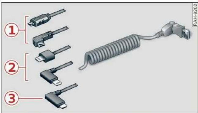
Fig. 148 Audi Genuine Accessories: USB adapter
You can connect your mobile devices through the Audi music interface to the MMI using the USB adapter and charge the battery at the same time.
You can purchase the USB adapter cable from an authorized Audi dealer or at specialty stores:
① USB adapter for devices with a micro USB connection
② USB adapter for devices with an Apple Lightning connection
③ USB adapter for devices with USB type C connection

Note
Handle the USB adapter carefully. Do not allow it to be pinched.

Tips
Mobile devices with an Apple Dock connector can only be charged using a USB adapter designed for devices with an Apple Dock connector. Data cannot be transmitted.
Audi music interface
Connect your mobile devices to the Audi music interface in order to operate them through the MMI and charge the batteries.
The Audi music interface USB ports are located in the storage compartment under the front and rear* center armrest and are labeled with the symbol. If multiple USB devices are connected to the USB ports (for example, a smartphone and a USB flash drive), all of these devices can be used as the playback source.
Connecting or charging mobile devices using a USB adapter
▶ Connect the matching USB adapter to the Audi music interface USB port and connect it to the mobile device, such as a smartphone.
The battery will charge automatically.
Mobile devices connected to the Audi music interface can be started and operated using the MMI → page 216.
Disconnecting a mobile device from the Audi music interface
▶ Remove the USB adapter cable from the Audi music interface.

WARNING
Driving requires your complete and undivided attention. As the driver, you have complete responsibility for safety in traffic. Never operate mobile devices while driving, because this increases the risk of an accident.

Note
– Pull the cable out of the Audi music interface carefully so that the USB ports are not damaged.
- Use a USB extension cable to connect devices that have an integrated USB connector (such as a USB stick) to reduce the risk of damage to your USB device and the Audi music interface.
- Extremely high or low temperatures that can occur inside vehicles can damage mobile devices and/or impair their performance. Never leave mobile devices in the vehicle in extremely high or low temperatures.

Tips
- Always follow the information found in page 78.
- When you switch the ignition off, the USB ports are still supplied with power until the energy management intervenes.
- Do not use an additional adapter cable or USB extension cable to connect mobile devices to the Audi music interface that already have a cable or that must be connected with a USB adapter cable (⇒ page 215, fig. 148). Using an additional adapter or US extension cable may impair functionality.
- Functionality is not guaranteed for mobile devices that do not conform to the USB 2.0 specification.
- USB hubs are not supported.
– Video playback through the Audi music interface is not supported on Apple and MTP devices (such as smartphones). - iPod or iPhone malfunctions also affect the operation of the MMI. Reset your mobile device in these situations.
– Audi recommends updating the iPod or iPhone software to the latest version. Refer to your mobile device owner's manual for more information. - The USB adapter on the Audi music interface will support iPod touch or iPhone devices from the 5th generation or newer with the lightning connector.
- A selection of supported devices can be found in the database for tested mobile devices at www.audi.com/mp3.
Playing media
Media sources
The following sources can be selected depending on the vehicle equipment:
- Amazon Alexa page 215.
- SD card page 212.
- USB page 215.
- DVD drive page 213.
- Connect external device: you can connect external devices via Bluetooth and use the Bluetooth audio player page 213, or you can connect an external device directly to the Audi music interface page 215.
- Connect online media page 214.
Accessing media
Playing media files using the MMI
Applies to: MMI: Select on the home screen: MEDIA > Source > a source. Depending on the connected device or online media service*, the symbol for a source may change. The device name may be displayed (for example: my-Phone).
▶ Select a track from the categories in the media center page 217.
Playing media files using the multifunction steering wheel
Requirement: a media drive must contain media files page 216.
▶ Select the Radio/Media tab using the multifunction steering wheel.
▶ Turn the left thumbwheel to display the playlist.
▶ To switch to a different source, press the button.
▶ To select a media file or a source, turn and press the left thumbwheel.
▶ To switch between radio and media, select the button > Switch to radio/Switch to media.

Tips
- For safety reasons, the video image is only displayed when the vehicle is stationary. Only the sound from the video plays while driving.
- Applies to: multifunction steering wheel: Depending on the selected function, operation through the MMI may be required.
Media center

Fig. 149 Upper display: media center view
Various categories are available in the media center for selecting media files or browsing through media sources.
You can browse through your music collection using the categories in the media center, such as albums. You can browse through the active source or any available source (for example, an SD card). While browsing through the media center, the music from the active source will continue to play.
Opening the media center
- Applies to: MMI: Searching any source: select on the home screen MEDIA > Source > a source > a category.
▶ Searching through the active source: select in the playback view page 218: ☐ > a category.
① Source symbol
The system will display the symbol for the source that is currently being searched. Depending on the connected device or online media service*, the symbol for a source may change. As an example, fig. 149 shows a USB stick connected to the Audi music interface.
② Source device name
The system will display the device name of the source that is currently being searched.
③ Categories
The media center will display categories depending on the connected device, the selected source content, and the connection type. The search is limited to the active source.
Search
If a source supports the search, then the category is displayed page 220.
Last played track
The last played media file will be played.
Artists
All available artists are displayed.
▶ Select: an artist > an album > a song.
Playlists
All playlists and smart playlists in the source are displayed.
▶ Select: a playlist > a song.
Smart playlists
Last played tracks: the tracks that were displayed last are displayed.
Most played tracks: the tracks that are played most frequently are displayed.
Directories
The folder structure or track/chapter list is displayed.
▶ Select: a folder > a song.
Compilations
You can control your playlists through the MMI.
▶ Select: a playlist > a song.
Composers
All available composers are displayed.
▶ Select: a composer > an album > a song.
Radio
▶ Press on a radio station.
Audio books
You can control your audio books on the MMI.
▶ Press on an audio book.
Podcasts
You can control your podcasts through the MMI.
▶ Select: a podcast > a podcast episode.
Genres
All available genres are displayed.
▶ Select: a genre > an artist > an album > a song.
Videos
All available video files are displayed.
▶ Press on a video.
Tracks
All available tracks are displayed.
▶ Press on a track.
Albums
All available albums are displayed.
▶ Select: an album > a track.

Note
Applies to: vehicles with Audi connect Infotainment
– Cloud services and category radio always require an Internet connection.
- Read the information about Audi connect, and be sure to note the connectivity costs section ⚠ in General information on page 179.

Tips
- Only the categories supported by the medium are available.
- For safety reasons, the video image is only displayed when the vehicle is stationary. Only the sound from the video plays while driving.
- When synchronizing a portable device with Cloud services, playlists may display incorrectly in the MMI. Use the media center in the device.
- Applies to: iPod/iPhone: Note the information about the Audi music interface and the supported devices page 215.
Media functions

Fig. 150 Upper display: left side: playback view, right side: playlist
Operating
Applies to: MMI: To open the playback view ①, select on the home screen: MEDIA > Source > a
source > a category (such as Artists > Album) > a track.
▶ To open the playlist ②, select List in the playback view ⑰.
The following functions may be available depending on the selected media source and the vehicle equipment:
| Symbol/Description | Description | |
| 3 | Categories menu | The media center categories are displayed based on the active source ⇒ page 217. |
| 4 | Source button | Displays sources in the Media menu. |
| 5 | Source/device name | Applies to: playback view: Device name of the source that is currently playing. |
| Applies to: media center view: Source that you are currently browsing ⇒ page 217. | ||
| 6 | Album cover in the play-back view | Requirement: a media source with album covers must be selected or the covers must be available online ⇒ page 221, Online additional data.Displays the current album cover.Displaying playlists: press on the cover. |
| 7 | Settings | See ⇒ page 221. |
| 8 | Filter | Filtering the current list. |
| 9 | Current track information | Display of Track and Artist. Highlights the track that is currently playing. |
| 10 | List | Browsing in the list: drag your finger upward or downward. |
| 11 | Album cover in the play-list | Requirement: a media source with album covers must be selected or the covers must be available online ⇒ page 221, Online additional data.Displays the current album cover. For tracks belonging to one album, the album cover is displayed one time. |
| 12 | More | Accessing options ⇒ page 220. |
| 13 | Off | Switching between off/playlist/track: press 13. |
| Playlist | The tracks in the current playlist will repeat continuously in a loop. | |
| Tracks | The current track will repeat continuously in a loop. | |
| 14 | K/DI | Selecting the previous/next track (or station/chapter): press K or D.Jumping to the beginning of a track: press K after the first ten seconds of play time. |
| 15 | D/II | Start or stop playback |
| 16 | Shuffle | When this function is switched on, all files in the playlist will play in random order. |
| 17 | List | The playlist 2 is displayed. |
| 18 | Playback position | You can adjust the playback position using the knob. |
| 19 | Info section | Display of Track, Artist, and Album. |
DVD functions
Applies to: vehicles with a DVD drive
Requirement: the vehicle must be stationary and a DVD must be playing.
The following functions are available in the play-back view:
- Display the DVD main menu: press on the upper display. Press DVD menu.
- Using the DVD main menu: press the desired function.
- Switching to the media functions: press on the upper display. Select: ↔ a chapter, or start the movie in the DVD main menu and press on the upper display.
- Adjusting the aspect ratio: press on the upper display. Select: Aspect ratio > an aspect ratio > OK ⇒ table on page 221.

Tips
Not all functions are available in every source and on every touch display.
Free text search
Applies to: vehicles with free text search
You can search in all active sources, for example for tracks and video files.
Opening the search
Requirement: the selected source must support the search function. The media center ⇒ page 217 is displayed.
▶ Press Search.
Entries that contain the entered search term are listed in the results list. Each result is marked with the symbol for a category in the media center page 217.
You can search for the following categories:
- Artists
- Albums
- Tracks
-Genres - Videos

Tips
Only files in the active source will be searched.
Options and settings
Options
Context-dependent functions and settings may be available depending on the selected source, the connected mobile device, and the connection type.
Requirement: the playback view must be displayed ① ⇔ page 218, fig. 150.
▶ Press More, or
Requirement: a list (for example, a playlist ② ⇒ page 218, fig. 150) must be displayed.
▶ Press and hold an element until the Options menu is displayed.
Play more like this
The track currently playing is quickly analyzed for features such as artist, genres, mood, and beat, and a smart playlist with similar tracks will be shown.
More from this album
Based on the track that is currently playing, an intelligent playlist with other tracks from this album will be displayed.
More from this artist
Based on the track that is currently playing, an intelligent playlist with other tracks from this artist will be displayed. The system will search for artists in the source that is currently playing.
More from this genre
Based on the track that currently playing, an intelligent playlist with other tracks from this genre will be displayed.
Save as a shortcut
See page 22, Shortcuts.
Play
The selected track or all tracks in the folder will be displayed.
Language 1)
You can set the language manually. The language and audio format options depend on the video DVD.
Subtitles 1)
You can manually select subtitles for playback. The languages available depend on the DVD.
Aspect ratio
The Auto aspect ratio setting is recommended. If you press on an aspect ratio, you will see a preview of the setting on the screen. Press OK to apply the selected aspect ratio.
The following table gives an overview of the aspect ratios. The possible aspect ratios depend on the source or video file being played.
| Aspect ratio | Description |
| Auto | The MMI detects the picture format of the source and displays the image in the optimal ratio. |
| 4:3, 16:9, Cinema | The image is fixed in the corresponding ratio. Select one of these options if the image is distorted or a section of the image is cut off or blurry when Auto is selected. |
| Zoom | The image is enlarged to fill the entire display. |
| Original | The image is displayed in the ratio of the source format. Select this option if the image is distorted or a section of the image is cut off or blurry when Auto is selected. |
Settings
Accessing settings
Applies to: MMI: Select on the home screen: MEDIA >
Online additional data
Requirement: the MMI must be connected to the Internet page 179.
If available, various information about the track currently playing (such as the cover) will be loaded from the Internet when this function is switched on.
DVD playback parental control\*
Playback of video DVDs can be restricted based on age restrictions using parental control.
Displaying the parental control menu
▶ Applies to: MMI: Select on the home screen: MEDIA > DVD playback parental control.
▶ Enter the PIN for parental control. The PIN set at the factory is 1234.
▶ Press OK.
Switching the rating level on and off
Requirement: the parental control menu must be displayed.
▶ Select: Set rating level > a rating level (for example, level 5) > ←, or
▶ To remove all restrictions, select Off.
Eight different protection levels can be set for parental control. If you set the parental control level at Level 5, all DVDs from levels 1-5 can be played. Video DVDs with a higher level will not play.
Changing the PIN
Requirement: the parental control menu must be displayed.
▶ Select: Change PIN > enter a new PIN for parental control > OK.
▶ Repeat the entry and press OK.

Tips
- Not all video DVDs have parental control.
- The protection levels for the parental control are based on the US standards from the Motion Picture Association of America (MPAA). Note that the age levels for video DVDs in European countries may differ.
- PIN entry for parental control will be locked for approximately one minute if you enter the incorrect PIN three times in a row. The PIN can only be reset by an authorized Audi dealer.
Supported media and file formats
Overview
The DVD drive*, SD card reader, and the USB storage device connection support the following media file properties:
| Audio files | Video files | ||||||||
| Support-ed media | SD/SDHC/SDXC/MMC memory cards: with a capacity of up to 256 GBDVD drive: audio CDs (up to 80 min) with CD text (artist, album, song)*, CD-ROMs with a capacity of up to 700 MB; DVD±R/RW; DVD video; DVD audio with audio tracks that are compatible with a DVD video player;Audi music interface: mobile devices ⇒ page 215 (such as an iPhone, MTP player, USB storage device in “USB Device Subclass 1 and 6” that conforms to USB 2.0: USB sticks, USB MP3 players (Plug-and-Play-capable), external USB flash drives and hard drives | ||||||||
| File sys-tem | Memory cards: exFAT, FAT, FAT32, NTFS.USB storage devices: FAT, FAT32, NTFS.USB mass storage device partitions (primary/logical*): two per USB connection.CD/DVD file systems: ISO9660, Joliet, UDF. | ||||||||
| Metadata | Album cover: GIF, JPG, PNG with max. 800x800 px.The album cover from the medium or from Grace-note* is displayed, depending on availability. | ||||||||
| Format | MPEG1/2Layer 3 | WindowsMediaAudio 9and 10 | MPEG2/4 | Opus | FLAC | ALAC | MPEG1/2 | MPEG4AVC(H.264) | WindowsMedia Video9 |
| File ex-tension | .mp3 | .wma | .m4a.m4b.aac | .opus.ogg.oga | .flac | .m4a | .mpg;.mpeg | .mp4.m4v.mov.avi | .wmv.asf |
| Playlists | .M3U; .PLS; .WPL; .M3U8; .ASX | ||||||||
| Character-istics | up to maximum 320 kbit/s and48 kHz sampling frequencies | 48 kHz sampling frequency | up to maximum 10 Mbit/s and1920x1080 px at maximum 30 fps | ||||||
| Numberof files | DVD drive*: max. 1,000 files per medium.USB mass storage device and memory cards: max. 50,000 files per medium; max.50,000 files per playlist/folder | ||||||||

Tips
– The media sources do not support the Windows Media Audio 9 Voice format.
- For compressing MP3 files, AUDI AG recommends a bit rate of at least 160 kbit/s. The display showing the remaining play time may differ for audio files with variable bit rate.
– Special characters (such as those in ID3 tag information) may display differently or may
not always display, depending on the system language.
- The manufacturer of the storage device can provide information about its "USB Device Subclass".
- Some MTP player functions are not supported, such as rating music tracks and video playback.
Troubleshooting
The information that follows lists some trouble-shooting options. They depend on the equipment.
| Problem | Solution |
| Audi music interface/Bluetooth audio player: the mobile device is not supported. | Read the instructions in the chapter ⇒ page 215, Multimedia connections/⇒ page 213, Bluetooth audio player. |
| Audi music interface: the mobile device is not recognized as a source. | For many mobile phones or mobile devices, playback is not possible when the battery level is too low (less than 5% charge level). The mobile device will only be recognized as a media source in the MMI after connecting if the battery charge level is sufficient. |
| Audi music interface: malfunctions during audio playback through an iPod/iPhone. | The Bluetooth audio player function is switched on. Switch this function off ⇒ page 227 when you are not using the Bluetooth audio player. |
| Audi music interface: audio play-back through the connected mobile device is not possible. | Make sure the USB mode MTP is selected in the settings on your mobile device. |
| Bluetooth audio player: interference with track display and audio playback. | Playback interference can occur when using the Bluetooth audio player if a music player app from a third party provider is open. AUDI AG recommends using the integrated media player on your Bluetooth device (such as a smartphone). |
| Online media: connection failed between the MMI and the myAudi app. | To establish a connection to the MMI, the MMI connection switch must be switched on in the myAudi app status screen. |
| Online media: no playback of online media. | Check if a suitable data plan has been purchased. |
| Wi-Fi hotspot: your Wi-Fi device is disconnected from the Wi-Fi hotspot. | Make sure the network optimization functions are switched off in the Wi-Fi settings or in the network settings for your Wi-Fi device. For additional information, refer to the user guide for your Wi-Fi device. |
Audi smartphone interface
Setup
Applies to: vehicles with Audi smartphone interface
You can connect your smartphone to the MMI with a cable or wirelessly* using the Audi smartphone interface. Certain content on your smartphone is adapted in the MMI while driving and can be operated through the MMI.
Requirement: the vehicle must be stationary and the ignition must be switched on. iPhone generation 5 or higher with Lightning connector and iOS 7.1.2 operating system or higher, or smartphone with Android Auto app and Android 5.0 Lollipop operating system or higher.
Applies to: MMI: Select on the home screen: SETTINGS > Connected devices > Audi smartphone interface > New connection.
- Connect your smartphone to the Audi music interface page 215 using a USB adapter page 215, fig. 148, or
To connect your iPhone wireless*, switch on the Bluetooth function and Wi-Fi on your iPhone. Open the CarPlay settings in your iPhone. In the MMI, press on your iPhone in the list of displayed devices.
▶ To update the list, press ↻.
▶ Follow the system instructions.
▶ Pay attention to any additional system prompts on your smartphone, if applicable.
Applies to: MMI: If you declined use of Apple CarPlay or Android Auto the first time you connected your smartphone, then select on the home screen: SETTINGS > Connected devices > Audi smartphone interface > a smartphone.
▶ Follow the system instructions.

WARNING
Driving requires your complete and undivided attention. As the driver, you have complete responsibility for safety in traffic. Never operate mobile devices while driving, because this increases the risk of an accident.

Note
Read the information about Audi connect, and be sure to note the connectivity costs section page 179.

Tips
- The functions that can be used depend on the following factors, among others:
– The brand of your smartphone
– The version of the operating system in your smartphone
– The software version of the app used
– The USB adapter cable and correct connection - Your cell phone service provider
-
The customized settings on your smartphone
-
One of the factors above or a combination of any of them could cause your smartphone to be incompatible with the Audi smartphone interface. Compatibility cannot be guaranteed for all types of smartphones. For more information and assistance, refer to the user guide and the manufacturer of your smartphone.
- Please note that you can only connect your smartphone via the front Audi music interface in order to use the Audi smartphone interface.
- Wireless CarPlay* is not available in all countries.
- Wireless CarPlay* is only possible in vehicles without a navigation system if the following requirement is met: the embedded SIM card for the vehicle must be logged into the mobile phone network page 179. Make sure the function page 176, Turn on car phone or data module is switched on.
- If the connected smartphone has voice control, you can operate your smartphone using the external voice recognition system page 27.
- The menu language shown in the MMI is based on the settings in your smartphone.
- Some MMI functions are not available when there is an active Audi smartphone interface connection.
- You cannot connect any mobile devices via Bluetooth when an Audi smartphone interface connection is active.
– Usage of the Audi smartphone interface depends on the availability of services through third party providers.
Troubleshooting
Applies to: vehicles with Audi smartphone interface
The information that follows lists some trouble-shooting options. They depend on the equipment.
– AUDI AG merely provides access to third party services through the MMI and does not assume any responsibility for the content of these services.
| Problem | Solution |
| Audi smartphone interface cannot be opened. | Check the battery charge level on your smartphone.Check the USB cable and use a different one if necessary.Check if Android Auto or Apple CarPlay is available in the country where the vehicle is being operated. |
| Android Auto: check if the Android Auto app is installed on your smartphone. | |
| Connecting the smartphone to the MMI failed. | Make sure that you are using the correct USB adapter and check if the USB adapter is connected correctly to your smartphone and the Audi music interface ⇒ page 215. |
| Apple CarPlay: check if Apple CarPlay is activated on your iPhone. | |
| Android Auto: check in the Android Auto app if Android Auto permits new vehicles. | |
| Wireless connection: open the settings for Bluetooth and CarPlay on your iPhone. Remove your vehicle. Open the connection manager in the MMI ⇒ page 227. Delete your iPhone in the Telephone 1 and Audi smartphone interface submenus. Repeat the connection process. Restart the MMI ⇒ page 19. Restart your iPhone. | |
| The smartphone is not automatically detected. | Make sure that you are using the correct USB adapter and check if the USB adapter is connected correctly to your smartphone and the Audi music interface ⇒ page 215.Check if the requirements needed to connect a smartphone have been met. |
Additional settings System settings
Introduction
General settings are described in this chapter. You can find specific settings in the chapters about those settings. The available settings depend on the vehicle equipment.
Date and time
▶ Applies to: MMI: Select on the home screen: SETTINGS > General > Date & time.
Possible settings:
- Set date and time automatically
- Date
- Time
- Date format
- Use 24h time format
- Automatic time zone
- Time zone
– Automatic daylight saving time - Manual daylight saving time
Measurement units
▶ Applies to: MMI: Select on the home screen: SETTINGS > General > Measurement units.
Possible settings:
- Speed
- Distance
- Temperature
- Pressure
- Consumption (engine)
- Volume
Language and keyboard
▶ Applies to MMI: Select on the home screen: SETTINGS > Language & keyboard.
Language
You can change the languages for the display, navigation announcements, and the voice recognition system.
Keyboard
See page 23.
Sound
Requirement: an audio source must be active.
- Applies to MMI: Select on the home screen: SETTINGS > Sound.
Possible settings:
- Treble
- Bass
- Balance/fader
– Speed-dependent volume control - Subwoofer
- Surround Level
Focus
You can optimize the sound distribution for various locations in the vehicle.
3D effect
You can adjust the intensity of the 3D effect. With the Medium setting, you will hear an optimal 3D effect for all sources.
Announcements and tones
▶ Applies to: MMI: Select on the home screen: SETTINGS > Announcements & tone.
Possible settings:
– Volume of announcements
- Welcome sound

WARNING
Adjust the volume of the audio system so that signals from outside the vehicle, such as police and fire sirens, can be heard easily at all times.

Tips
The volume is automatically adjusted to a pre-set level when the MMI is switched on.
Bluetooth
▶ Applies to: MMI: Select on the home screen: SETTINGS > Connection settings > Bluetooth.
Bluetooth
You can select a setting for visibility of the MMI to other Bluetooth devices. To connect a new Bluetooth device, the Visible setting must be selected. If Invisible is selected, a Bluetooth connection will only be possible with paired devices. If Off is selected, no Bluetooth device can be connected.
Bluetooth audio player
When this function is switched on, the profile will load automatically when your Bluetooth audio player is within range.
Bluetooth name
The MMI's Bluetooth name is displayed and can be changed.
Software update
Applies to: MMI: Select on the home screen: SETTINGS > System maintenance > Software update.
▶ If necessary, insert a storage medium with the update data into the corresponding drive
⇒ page 222.
▶ Press Search for updates.
▶ Press on the desired update.
▶ Press Next.
▶ Follow the system instructions.

WARNING
- Perform the installation only when the vehicle is stationary. Otherwise, this increases the risk of an accident
- If the installation fails, contact an authorized Audi dealer or authorized Audi Service Facility immediately to have the malfunction corrected.

Note
The connection costs for the software update are included in the Audi connect pricing.

Tips
The length of the process depends on the size of the update.
Factory default settings
▶ Applies to: MMI: Select on the home screen: SETTINGS > System maintenance > Restore factory settings.
▶ Select the desired functions individually, or
▶ Select the option Select all.
▶ Press Apply. The settings will be reset. The key user will remain stored.
▶ To also delete the key user, press Remove key user.
▶ To completely delete a smartphone that is paired with the Audi smartphone interface, reset Audi smartphone interface and Bluetooth.

Tips
- Make sure that not only the settings were deleted but also the stored data, if necessary.
- The system may restart when the settings are reset. This may take a few minutes.
Connected devices
Connection manager
Requirement: the vehicle must be stationary and the ignition must be switched on.
Applies to: MMI: Select on the home screen: SETTINGS > Connected devices.
Possible menu items:
- Telephone 1
- Telephone 2
- Audio player
- Wi-Fi hotspot
- Headset
myAudi app
This function is available if the myAudi app is installed on your mobile device and started, and if the mobile device is connected with the vehicle's Wi-Fi hotspot.
Audi smartphone interface
You can connect your smartphone to the MMI ⇒ page 224.

Note
Read the information about Audi connect, and be sure to note the connectivity costs section page 179.
Connection options
Requirement: the connected devices menu must be displayed page 227.
Connecting a device
Requirement: Bluetooth visibility must be activated in the MMI page 227 and mobile device.
▶ Press on a menu item, such as Telephone 1.
▶ To search for and connect your mobile device, press New connection page 166.
Selecting a connected device
▶ Press on a menu item, such as Telephone 1.
▶ Press on the desired mobile device in the list of displayed devices. The connection will be made.
Disconnecting a connected device
▶ Press on a menu item, such as Telephone 1.
▶ Press on the connected mobile device. The selected device will be disconnected from the MMI.
Deleting a device
▶ Press on a menu item, such as Telephone 1.
▶ Press and hold an element until the Options menu is displayed.
▶ Press Delete.
If a device is listed multiple times, it will be deleted from all menu items.
Additional options
Depending on the selected function, additional options may be available.
Requirement: the connected devices menu must be displayed page 227.
▶ Press on a menu item, such as Telephone 1.
▶ Press and hold an element until the Options menu is displayed.
Bluetooth profiles
You can switch desired profiles on or off separately in the MMI.
Favorite
To set a paired mobile device as the default phone, activate this function in the MMI.
When the mobile device is in range and the Bluetooth function on the mobile device and in the MMI is switched on, the default phone will be given priority over the other Bluetooth devices and will be connected directly to the MMI.
Legal information
General information
Information on the software licenses can be found online at www.audi.com/softwareinfo.
Information in the MMI
Applies to: MMI: Select on the home screen: SETTINGS > General.
License subscription
Version information
Legal information
Possible options:
- Software information
- About Audi connect
Audi smartphone interface
Applies to: vehicles with Audi smartphone interface
Requirement: a smartphone must be connected to the MMI page 224.
▶ Applies to: MMI: Select on the home screen: SETTINGS > Connected devices > Audi smartphone interface.
▶ Press and hold an element until the Options menu is displayed.
▶ Press Legal notes.
Instrument cluster
Requirement: the vehicle must be stationary and the ignition must be switched on.
▶ Select in the instrument cluster: vehicle functions tab page 12.
▶ Press and hold the ☐ button on the multifunction steering wheel until the display appears.
Possible options:
- Engine code
- Software information
- Version information
Head-up display
Applies to: vehicles with head-up display
Requirement: the vehicle must be stationary and the ignition must be switched on. The head-up display is switched on.
Applies to: MMI: Select on the home screen: SETTINGS > Display & brightness > Head-up display > Display contents > Show the license text in the head-up display.
Checking and Filling
Fuel
Types of gasoline
The correct gasoline grade is stated on the inside of the fuel filler door.
The vehicle is equipped with a catalytic converter and must only be driven with unleaded gasoline.
Audi recommends using TOP TIER Detergent Gasoline. For additional information on TOP TIER Detergent Gasoline, visit www.toptiergas.com.
The individual gasoline grades are differentiated by octane ratings. This value is given with (R +M)/2 equating to AKI or in RON.
The headings below match the sticker in the fuel filler door (examples):
UNLEADED FUEL ONLY MIN. (R+M)/2 87 Regular / MIN. RON 91 Regular
Use regular gasoline with minimum 87 AKI / 91 RON ⇒ ⚠.
Audi recommends using premium gasoline with minimum 91 AKI / 95 RON to achieve the rated horsepower and torque.
UNLEADED FUEL ONLY PREMIUM MIN. (R +M)/2 91 / SUPER MIN. RON 95
Using premium gasoline with minimum 91 AKI / 95 RON is recommended.
If premium gasoline is not available, you can also use regular gasoline 87 AKI / 91 RON. However this does reduce the engine power slightly.
UNLEADED FUEL ONLY PREMIUM MIN. (R +M)/2 93 / SUPER PLUS MIN. RON 98
Using premium plus gasoline with at least 93 AKI / 98 RON is recommended.
If no premium plus gasoline is available, you can also use premium gasoline with 91 AKI / 95 RON. However this does reduce the engine power slightly.

Note
- Filling the tank just one time with leaded fuel or other metallic additives will cause permanent deterioration to the catalytic converter function.
- When gasoline with an octane rating that is too low is used, high speeds or heavy engine load can lead to engine damage.

Tips
The vehicle may be filled with fuel that has a higher octane rating than what is required by the engine.
Gasoline mixture
Gasoline with alcohol or MTBE (Methyl-Tert-Butyl-Ether)
You can use unleaded gasoline mixed with alcohol or MTBE (generally labeled as oxygenated compounds) as long as the fuel meets the following conditions:
Gasoline with methanol content (methyl alcohol or methanol)
– Anti-Knock Index is at least 87 AKI
- No more than 3% methanol
- More than 2 % solvent
Gasoline with ethanol content (ethyl alcohol or ethanol)
– Anti-Knock Index is at least 87 AKI
- No more than 15% ethanol
Gasoline with MTBE content
– Anti-Knock Index is at least 87 AKI
- No more than 15% MTBE
Gasoline adapted to the season
Many gasoline fuels are adapted to the seasons. When the season changes, we recommend refueling at high-traffic gas stations. It is more likely that the gasoline will be suitable for the season there.

Note
– Gasoline with methanol content that does not meet the specified conditions may cause
corrosion damage and damage to plastic or rubber components in the fuel system.
- Do not use gasoline that does not meet the specifications.
- If you are unable to find out if a specific gasoline mixture meets the specifications, ask the gas station operator or their fuel supplier.
- Do not use any gasoline mixture whose composition cannot be identified.
- Audi does not assume any responsibility for damage to the fuel system or for performance problems caused by using gasoline mixtures different from those specified. This type of damage also does not fall under the New Vehicle Limited Warranty or under the emissions control system warranty.
- If you notice a higher fuel consumption or poor handling or performance problems due to such gasoline mixtures, we recommend fueling with unblended gasoline.
Gasoline additives
An important issue for many automobile manufacturers is combustion residue in the engine that results from the use of certain fuels.
Although types of gasoline differ depending on the manufacturer, there are similarities. Certain substances in the gasoline may cause deposits in the engine. Additives in the gasoline that should keep the engine and fuel system clean do not all function equally.
Audi recommends using TOP TIER Detergent Gasoline. For additional information on TOP TIER Detergent Gasoline, visit www.toptiergas.com.
If you use incorrect fuels over a long period of time, the maximum engine performance may be impaired by combustion residue.
Note
– Damage or malfunctions caused by the use of incorrect types of gasoline are not covered by the New Vehicle Limited Warranty.
- Only gasoline additives that have been approved by Audi may be used.
Refueling
Fueling procedure

natural_image
Close-up of a car's door panel with a red arrow icon and partial white plastic clip (no text or symbols)Fig. 151 Right rear side of the vehicle: opening the fuel filler door

natural_image
Illustration of an electric vehicle charging plug with a red battery, showing internal components and wiring (no text or symbols)Fig. 152 Fuel filler door with attached fuel cap
The fuel filler door is unlocked or locked by the central locking system.
▶ Unlock the vehicle if necessary.
▶ Press on the left side of the fuel filler door to open it fig. 151.
▶ Unscrew the tank cap counterclockwise.
▶ Place the cap from above on the open fuel filler door fig. 152.
- Insert the fuel pump nozzle all the way into the fuel filler neck.
▶ Begin fueling. Once the fuel pump nozzle turns off the first time, the fuel tank is full. Do not continue fueling, or else the expansion space in the tank will be filled with fuel.
▶ After the fuel pump has switched off, wait five seconds before removing the nozzle to allow the rest of the fuel to finish dripping into the fuel tank.
▶ Turn the fuel cap clockwise until it clicks into place.
▶ Close the fuel filler door and then press on the left side until it latches.
The correct fuel type for your vehicle can be found on a label located on the inside of the fuel filler door. For additional information on fuel, see page 230.
For the tank capacity in your vehicle, refer to the Technical Data page 302.
To reduce the risk of fuel leaking out or vapors escaping, make sure that the fuel tank is closed correctly. Otherwise the 1) indicator light will turn on.
If the central locking system malfunctions, there is a fuel filler door emergency release ⇒ page 233.
Messages
Tank system: malfunction! Please contact Service
There is a malfunction in the fuel tank system. Drive to an authorized Audi dealer or authorized Audi Service Facility immediately to have the malfunction corrected.

WARNING
Improper fueling procedures and improper handling of fuel can lead to explosions, fires, severe burns, and other injuries.
- Do not smoke. Keep away from open flames.
- The ignition must be switched off when refueling.
- Mobile devices, radio devices, and other radio equipment should always be switched off when refueling. Electromagnetic rays could cause sparks and start a fire.
- If you do not insert the fuel pump nozzle all the way into the filler tube, then fuel can leak out. Spilled fuel can ignite and start a fire.
- Never get into the vehicle when refueling. If there is an exceptional situation where you must enter the vehicle, close the door and touch a metal surface before touching the fuel pump nozzle again. This will reduce the risk of electrostatic discharge that can cause
flying sparks. Sparks can start a fire when refueling.

WARNING
Transporting fuel containers inside the vehicle is not recommended. Fuel could leak out of the container and ignite, especially during an accident. This can cause explosions, fires, and injuries.
- If you must transport fuel in a fuel container, note the following:
- Always place the fuel container on the ground before filling. Never fill the fuel container with fuel while it is inside or on the vehicle. Electrostatic discharge can occur while refueling and the fuel vapors could ignite.
- When using fuel containers made of metal, the fuel pump nozzle must always remain in contact with the container to reduce the risk of static charge.
- Insert the fuel pump nozzle as far as possible into the filler opening while refueling.
– Follow the applicable legal regulations in the country where you are driving when using, storing and transporting fuel containers.
- Make sure that the fuel container meets the industry standards, for example ANSI or ASTM F852-86.

Note
- Remove fuel that has overflowed onto any vehicle components immediately to reduce the risk of damage to the vehicle.
- Never drive until the fuel tank is completely empty. The irregular supply of fuel that results from that can cause engine misfires. Uncombusted fuel may enter the exhaust system and increase the risk of damage to the catalytic converter.

For the sake of the environment
- Do not overfill the fuel tank, or fuel could leak out when the vehicle is warming up.
- Fuel should never enter the sewer system or come into contact with the ground.

Tips
The fuel filler door on your vehicle does not lock if you lock the vehicle from the inside using the central locking switch.
Fuel filler door emergency release
Applies to: vehicles with manual fuel filler door release
If the central locking system malfunctions, the fuel filler door can be unlocked manually.

Fig. 153 Right side trim in the luggage compartment: fuel filler door emergency release
The emergency release mechanism is located behind the right side trim panel in the luggage compartment ① fig. 153.
▶ To release the fuel filler door, loosen the red loop from the retainer ①. Carefully pull on the red loop ② ⇒ !.
▶ Press on the left side of the fuel filler door to open it page 231, fig. 151.

Note
Only pull on the loop until you feel resistance. You will not hear it release. If you continue to pull, you could damage the emergency release mechanism.
Emissions control system
General information

WARNING
The temperature of the exhaust system is high, both when driving and after stopping the engine.
- Never touch the exhaust tail pipes once they have become hot. This could result in burns.
- Do not park your vehicle over flammable materials such as grass or leaves because the high temperature of the emissions system could start a fire.
- Do not apply underbody protectant in the exhaust system area, because this increases the risk of fire.
Catalytic converter
Follow the safety precautions page 233, General information.
The vehicle may only be driven with unleaded gasoline, or the catalytic converter will be destroyed.
Never drive until the tank is completely empty. The irregular supply of fuel that results from that can cause engine misfires. Uncombusted fuel could enter the exhaust system, which could cause overheating and damage to the catalytic converter.
Malfunction Indicator Lamp (MIL)
If the indicator light blinks or turns on, there is a malfunction that is causing poor emissions quality and that could damage the catalytic converter. Drive slowly to an authorized Audi dealer or authorized Audi Service Facility to have the malfunction corrected.
The indicator light can also turn on if the fuel filler cap is not closed correctly page 231 1) .
Engine compartment
General information
Special care is required if you are working in the engine compartment
When performing work in the engine compartment, such as checking and filling fluids, there is a risk of injury, scalding, accidents, and burns. For this reason, follow all the warnings and general safety precautions provided in the following information. The engine compartment is a dangerous area in the vehicle.

WARNING
– Turn the engine off.
- Switch the ignition off.
- Set the parking brake.
- Select the "P" (Park) selector lever position.
- Allow the engine to cool.
- Keep children away from the engine compartment.
- Never spill fluids on a hot engine. These fluids (such as the freeze protection contained in the coolant) can catch fire.
- Avoid short circuits in the electrical system.
- Never reach into the radiator fan. The fan is temperature-controlled and can turn on suddenly, even when the ignition is switched off.
- Never open the hood when there is steam or coolant escaping from the engine compartment, because there is a risk that you could be burned. Wait until no steam or coolant is escaping.
- The cap on the coolant expansion tank must never be opened when the coolant is hot. The cooling system is under pressure. There is a risk of burns
- To protect your face, hands, and arms from hot steam or coolant, cover the cap with a thick cloth when opening.
- Do not remove the engine cover under any circumstances. This increases the risk of burns.
- Due to the risk of electric shock, never touch the ignition cable or other components in
the electronic high-voltage ignition system when the engine is running or is starting.
- If a gear is engaged while the vehicle is stationary and the engine is running, do not press the accelerator pedal inadvertently. Pressing the accelerator pedal will cause the vehicle to move, and this could result in an accident.
- If inspections or repairs must be performed while the engine is running, moving components (such as the ribbed belt, generator, and radiator fan) pose an additional risk.
- Set the parking brake first and select the "P" (Park) selector lever position.
- Always make sure that no parts of the body, jewelry, ties, loose clothing, and long hair can be caught in moving engine components. Before any work, always remove any jewelry and/or ties, tie back long hair, and make sure all clothing fits close to the body to reduce the risk of anything becoming caught in engine components.
– Pay attention to the following warnings listed when work on the fuel system or on the electrical equipment is required. - Do not smoke.
– Never work near open flames.
– Always have a working fire extinguisher nearby. - All work on the battery or electrical system in your vehicle can result in injuries, chemical burns, accidents, or burns. Because of this, all work must be performed only by an authorized Audi dealer or authorized Audi Service Facility.
- Limit your exposure to exhaust and chemicals to as short a time as possible.

WARNING
California Proposition 65 Warning:
- Engine exhaust, some of its constituents, and certain vehicle components contain or emit chemicals known to the State of California to cause cancer and birth defects and reproductive harm. In addition, certain fluids contained in vehicles and certain products of component wear contain or emit
chemicals known to the State of California to cause cancer and birth defects or other reproductive harm.
- Battery posts, terminals and related accessories contain lead and lead compounds, chemicals known to the State of California to cause cancer and reproductive harms. Wash hands after handling.

Note
When filling fluids, be sure not to add any fluids to the wrong reservoirs. Otherwise severe malfunctions and engine damage will occur.

For the sake of the environment
You should regularly check the ground under your vehicle in order to detect leaks quickly. If there are visible spots from oil or other fluids, bring your vehicle to an authorized Audi dealer or authorized Audi Service Facility to be checked.
Opening and closing the hood
The hood is released from inside the vehicle.

natural_image
Interior view of a car showing a red car seatbelt with a white logo, no visible text or symbolsFig. 154 Footwell: release lever
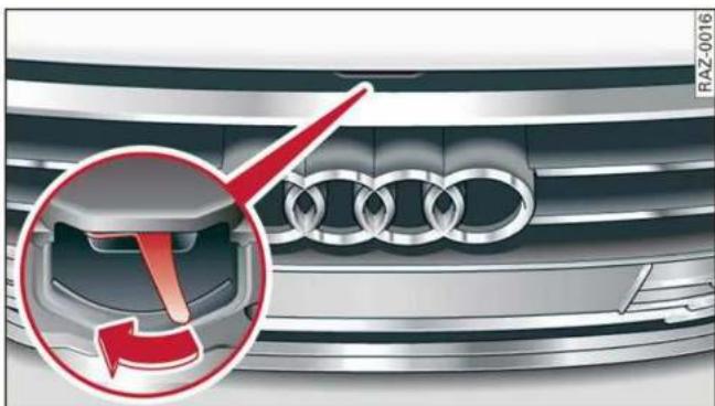
natural_image
Close-up of an Audi car grille with a red arrow highlighting the engine compartment (no text or symbols visible)Fig. 155 Unlocked hood: lever
Make sure the wiper arms are not raised up from the windshield. Otherwise the paint could be damaged.
Opening the hood
▶ With the door open, pull the lever ≈1) below the instrument panel in the direction of the arrow fig. 154.
▶ Raise the hood slightly page 234.
▶ Press the lever fig. 155 in the direction of the arrow. This releases the hooks.
▶ Open the hood.
Closing the hood
▶ Push the hood down until you override the force of the strut.
▶ Let the hood fall lightly into the latch. Do not press it in. ⇒ ⚠️.
Message

Warning! Hood is not locked. Stop vehicle I check the lock
The hood latch is not locked correctly. Stop immediately and close the hood.

WARNING
- Never open the hood when there is steam or coolant escaping from the engine compartment, because there is a risk that you could be burned. Wait until no steam or coolant is escaping.
- For safety reasons, the hood must always be latched securely while driving. Because of this, always check the hood after closing it to make sure it is latched correctly. The hood is latched if the front corners cannot be lifted.
- If you notice that the hood is not latched while you are driving, stop immediately and close it, because driving when the hood is not latched increases the risk of an accident.
Engine compartment overview
The most important check points.

Fig. 156 Typical location of the reservoir and the engine oil filler opening (example)
Follow the safety precautions page 234.
① Jump start point (+) under a cover, (-) with hex head screw page 245, Charging the 12 Volt vehicle battery, page 283, Jump starting
② Coolant expansion tank (⊥) ⇒ page 241
③ Sticker* for engine oil specification
⇒ page 236
④ Engine oil filler opening (☐) ⇒ page 238
⑤ Brake fluid reservoir (☐) under a cover
⇒ page 242
⑥ Washer fluid reservoir (💡) ⇒ page 245
The engine oil filler opening may be located in a different area depending on the specific engine.
Engine oil
If the engine oil level is too low
If you need to add engine oil, use an oil that is listed on the sticker. The sticker is located at the front of the engine compartment page 236, fig. 156.
If the recommended engine oil is not available, in an emergency you may add a maximum of 1 quart (1 liter) of ACEA C3 or API SN engine oil one time until the next oil change.
For more information on the correct engine oil for your vehicle, contact an authorized Audi dealer or authorized Audi Service Facility. Have the oil changed by an authorized Audi dealer or authorized Service Facility.
Audi recommends
-Castrol EDGE PROFESSIONAL
Audi recommends using the LongLife high-performance engine oil from Audi Genuine Parts.
Messages
Engine oil pressure
Turn off engine. Oil pressure too low
Stop driving and switch the engine off. Check the engine oil level page 237.
- If the engine oil level is too low, add engine oil page 238. Only continue driving once the indicator light turns off.
- If the engine oil level is correct and the indicator light still turns on, turn the engine off and do not continue driving. See an authorized Audi dealer or authorized Audi Service Facility for assistance.
Engine oil level

Please add oil immediately
Stop driving and switch the engine off. Check the engine oil level page 237 and add engine oil immediately page 238.

Please add max. x qt (x l) oil. You can con- ue driving
Add the amount of oil shown immediately page 238.
Reducing the oil level

Please reduce oil level
There is too much oil in the engine and there is a risk of damaging the catalytic converter or engine. Drive to an authorized Audi dealer or authorized Audi Service Facility immediately to have engine oil extracted if necessary. Avoid high engine speeds, full acceleration, and heavy engine loads.
Engine oil sensor

Oil level sensor: oil change necessary. Please contact Service
Fuel has entered the engine oil. This will cause the engine oil level to rise slowly and the engine oil quality to decrease. Do not extract engine oil to reduce the level, because this will increase the risk of engine damage. Drive to an authorized Audi dealer or authorized Audi Service Facility immediately to have engine oil extracted.

Oil level system: malfunction! Please con- t Service
The sensor that checks the engine oil level has malfunctioned. Drive immediately to an authorized Audi dealer or authorized Audi Service Facility to have the malfunction repaired.

Oil pressure sensor: malfunction! Please contact Service
The sensor that checks the engine oil pressure has malfunctioned. Drive immediately to an authorized Audi dealer or authorized Audi Service Facility to have the malfunction repaired.
Engine warm-up request

Please drive to warm up engine
Fuel has entered the engine oil, either due to low outside temperatures or frequent short drives. Drive until the engine is warm so that the fuel in the engine oil will evaporate. Avoid high engine speeds, full accelerating, and heavy engine loads when doing this.

Tips
The oil pressure warning is not an oil level indicator. Always check the oil level regularly.
Checking the engine oil level
The engine oil level can be checked in the MMI.
Follow the safety precautions in General information on page 234.
▶ Park the vehicle on a level surface.
▶ Shut the engine off when it is warm.
▶ Switch only the ignition back on.
▶ Wait approximately two minutes.
▶ Applies to: MMI: Select on the home screen:
VEHICLE > Settings & Service > Oil level.
Read the oil level in the display. Add engine oil if the bar in the oil level indicator is just below "min" page 238.

Note
If the engine oil level is too low or too high, there is a risk of engine damage.

Tips
The oil level indicator in the display is only an informational display. If the oil level is too low, a minimum oil warning appears in the instrument cluster. Add oil and close the hood.
The current oil level will be displayed on the MMI the next time the ignition is switched on.

Tips
The engine oil consumption may be up to 0.5 quart/600 miles (0.5 liter/1,000 km), depending on driving style and operating conditions. In RS models, the oil consumption may be up to 1 qt/600 mi (0.8 L/1,000 km). Consumption may be higher during the first 3,000 miles (5,000 km). The engine oil level must be checked regularly. It is best to check each time you refuel your vehicle and before long drives.
- Because of the lubrication and cooling of the engine, combustion engines consume oil. The oil consumption varies depending on the engine and may change during the service life of the engine. Engines generally consume more oil at the beginning during the break-in period. Then oil consumption stabilizes after the break-in period.
- Under normal conditions, oil consumption depends on the quality and viscosity of the oil, the engine RPM, the climate conditions, and the road conditions. The dilution of oil from condensation or fuel residue as well as the age of the oil also play a role. Because engine wear increases with mileage, oil consumption will increase again over time until it may be necessary to replace worn components.
- Because all these variables play a role, it is not possible to define an oil consumption standard. Therefore, the oil level must be checked regularly.
- If you believe that your engine has increased its oil consumption, contact an authorized Audi dealer or authorized Audi Service Facility to determine the cause. Please note that an exact oil consumption measurement must be done with the necessary care and accuracy and may take time. An authorized Audi dealer or authorized Audi Service Facility is trained in accurately measuring the oil consumption.
- You can find information on engine oil and engine oil capacities for the USA at www.
audiusa.com/help/maintenance, or for Canada at www.audi.ca/ca/web/en/ customer-area/care-and-maintenance/ audi-service-schedules.html, or call 800-822-2834.
Adding engine oil

natural_image
Circular icon with icons of an open book and a water drop, no text or symbols presentFig. 157 Engine compartment: engine oil filling opening cover (example)
Follow the safety precautions page 234, General information.
▶ Turn the engine off.
▶ Open the hood page 235.
▶ Unscrew the cap ➕ for the engine oil filler opening ⇒ fig. 157.
▶ Carefully add 0.5 quart (0.5 liter) of the correct oil page 236.
▶ Close the engine oil filler opening cap.
▶ Close the hood page 235.
▶ Restart the ignition after two minutes and read the current oil level in the MMI page 237, Checking the engine oil level.
▶ Add more oil if necessary.

WARNING
- When adding oil, do not let oil drip onto hot engine components. This increases the risk of a fire.
- You must close the cap on the oil filler opening correctly so that oil does not leak out on-to the hot engine and exhaust system when the engine is running, because this is a fire hazard.
- Always clean skin thoroughly if it comes into contact with engine oil.
- Engine oil is poisonous and must be kept out of reach of children.
- Store the engine oil securely in the original container.

Note
- The New Vehicle Limited Warranty does not cover damage or malfunctions if the recommended intended use of the vehicle and maintenance measures listed in the Audi Owner's Manual and the Warranty & Maintenance Booklet were not followed.
- Only use high-grade engine oil that explicitly meets the Audi oil quality standard for your vehicle. Using another oil may cause severe vehicle damage.
- Do not mix any additives with the engine oil. Additives may cause engine damage that is not covered by your New Vehicle Limited Warranty.

For the sake of the environment
- Oil should never enter the sewer system or come into contact with the ground.
– Follow the legal regulations in the country where you are located when disposing of empty oil containers.
Changing engine oil
We recommend having the oil changed at an authorized Audi dealer or authorized Audi Service Facility.
Follow the safety precautions page 234, General information.
The engine oil must be changed at the intervals specified in the Warranty & Maintenance Booklet. This is very important because the lubrication function of the oil gradually declines during regular vehicle operation.
The engine oil should be changed more frequently under certain circumstances. Have the oil changed more frequently if you often drive short distances, your vehicle is predominantly in stop-and-go traffic situations, is in very dusty environments, or is operated for long periods of time in temperatures below zero.
Cleansing additives in the oil make fresh oil appear darker after the engine has run briefly. This is normal and no reason to change the engine oil more frequently than recommended.
Because correctly disposing of engine oil is difficult and special tools and technical knowledge are needed for an oil change, having your engine oil changed by an authorized Audi dealer or authorized Audi Service Facility is recommended.
If you change the engine oil yourself, please note the following important information:

WARNING
If you change the engine oil on the vehicle yourself, the following precautions must be followed:
- Wear protective eyewear.
- Due to the risk of scalding, allow the engine to cool down sufficiently.
- Maintain enough distance when you are removing the oil drain plug. While doing this, keep your forearm parallel to the ground to reduce the risk of hot oil dripping down your arm.
- Drain the oil into a container designed for this purpose that is large enough to hold the full amount of oil in your engine.
- Engine oil is poisonous. Always store out of reach of children.
- Prolonged contact of used engine oil with the skin may cause skin damage. Always wash oil off immediately with soap and water to protect your skin.

Note
Do not mix any additives with the engine oil. Additives may cause engine damage that is not covered by your New Vehicle Limited Warranty.

For the sake of the environment
– Before changing the engine oil, make sure you can dispose of the used engine oil correctly.
- Engine oil must always be disposed of correctly. Do not dump it in the yard, in the forest, or in open water, river channels, or sewers.
– Have your used engine oil recycled by bringing it to a used oil collection site or contact a gas station.
Cooling system
Coolant
The engine cooling system is filled with a mixture of purified water and coolant additive at the factory. This coolant must not be not changed.
The coolant level is monitored using the indicator light. However, occasionally checking the coolant level manually is recommended.
Messages
Turn off engine and check coolant level. See owner's manual
The coolant level is too low.
Stop driving and switch the engine off. Check the coolant level page 241.
- If the coolant level is too low, add coolant page 241. Only continue driving once the indicator light turns off.
Coolant temperature: too high. Let engine run while vehicle is stationary
Let the engine run at idle for a few minutes to cool off, until the indicator light turns off.
- If the indicator light does not turn off, do not continue driving the vehicle. See an authorized Audi dealer or authorized Audi Service Facility for assistance.
Coolant system: malfunction! Please turn off engine
Do not continue driving, shut the engine off, and switch the ignition off.
– See an authorized Audi dealer or authorized Audi Service Facility for assistance.
Coolant additive
The coolant additive is made of anti-freezing and corrosion protection agents. Only use the following coolant additives. These additives may be mixed with each other.
| Coolant additive | Specification |
| G12evo | TL 774 L |
| G12++ | TL 774 G |
| G13 | TL 774 J |
The amount of coolant additive that needs to be mixed with water depends on the climate where the vehicle will be operated. If the coolant additive percentage is too low, the coolant can freeze and damage the engine.
| Coolant additive | Freeze protection | |
| Warm regions | min. 40% max. 45% | min. -13 °F (-25 °C) |
| Cold regions | min. 50% max. 55% | max. -40 °F (-40 °C) |

Note
- Before winter weather begins, have an authorized Audi dealer or authorized Audi Service Facility check if the coolant additive in your vehicle matches the percentage appropriate for the climate. This is especially important when driving in colder climates.
- If the appropriate coolant additive is not available in an emergency, do not add any other additive. You could damage the engine. If this happens, only use water and restore the correct mixture ratio with the specified coolant additive as soon as possible.
- Only refill with new coolant.
- Radiator sealant must not be mixed with the coolant.
- Due to the risk of engine damage, the cooling system should only be refilled by an authorized Audi dealer or authorized Audi Service Facility. An authorized Audi dealer or authorized Audi Service Facility can also provide you with important information about the recommended coolant additive.
Checking coolant

Fig. 158 Engine compartment - Coolant expansion tank:
① cover with release button; ② markings
Follow the safety precautions page 234, General information.
Checking the coolant level
▶ Park the vehicle on a level surface.
▶ Switch the ignition off.
▶ Open the hood page 235.
▶ Check the coolant level in the coolant expansion tank page 236, fig. 156 using the outer markings ② fig. 158. The coolant level must be between the markings ② when the engine is cold. When the engine is warm it can be slightly above the upper marking.
▶ When you add coolant to the expansion tank, please refer to page 240, Cooling system.
Adding coolant
Requirement: there must be a residual amount of coolant in the expansion tank !.
If you must add coolant, use a mixture of water and coolant additive. Mixing the coolant additive with distilled water is recommended.
▶ Allow the engine to cool.
▶ Place a large, thick towel on the coolant expansion tank cap.
▶ Push the release button ① ⇒ fig. 158 on the cap and carefully turn it to the left until you feel resistance ⇒ ⚠️.
- Push the release button again and remove the cap completely.
- Add coolant mixed in the correct ratio page 240 up to the MAX marking.
▶ Make sure that the fluid level remains stable. Add more coolant if necessary.
▶ Turn the cap to the right to tighten it until you feel resistance a second time.
Coolant loss usually indicates that there is a leak. Immediately drive your vehicle to an authorized Audi dealer or authorized Audi Service Facility and have the cooling system inspected. If the cooling system is not leaking, coolant loss can result from the coolant boiling due overheating and then being forced out of the cooling system.

WARNING
- The engine compartment in any vehicle can be a dangerous area. Stop the engine and allow it to cool before working in the engine compartment. Always follow the information found in page 234, General information.
- Never open the hood if you can see or hear steam or coolant escaping from the engine compartment. This increases the risk of burns. The cooling system is under pressure. When you no longer see or hear steam or coolant escaping, you may open the engine compartment with caution.
- When working in the engine compartment, remember that the radiator fan can switch on even if the ignition is switched off, which increases the risk of injury.
- Coolant additive and coolant can be dangerous to your health. For this reason, store the coolant in the original container and away from children. There is a risk of poisoning.

Note
Do not continue driving if the coolant expansion tank is empty. Do not add any coolant, because air could enter the cooling system and damage the engine. See an authorized Audi dealer or authorized Audi Service Facility for assistance.
Brake fluid

Fig. 159 Engine compartment: cap on brake fluid reservoir
Follow the safety precautions page 234, General information.
Checking the brake fluid level
▶ Slide the cover that is located below the windshield wipers on the driver's side toward the windshield and remove the cover.
▶ Read the brake fluid level on the brake fluid reservoir page 236, fig. 156. The brake fluid level must be between the MIN and MAX markings △.
The brake fluid level is monitored automatically.
Message
BRAKE / ☐ Brakes: stop vehicle and check brake fluid level
Stop the vehicle and check the brake fluid level. See an authorized Audi dealer or authorized Audi Service Facility for assistance.
Changing the brake fluid
Brake fluid should be changed at regular intervals. Have the brake fluid changed by an authorized Audi dealer or authorized Audi Service Facility. The authorized Audi dealer or authorized Audi Service Facility will inform you of the replacement intervals.

WARNING
- If the brake fluid level is below the MIN marking, it can impair the braking effect and driving safety, which increase the risk of an accident. Do not continue driving. See an au-
thorized Audi dealer or authorized Audi Service Facility for assistance.
- If the brake fluid is old, bubbles may form in the brake system during heavy braking. This could impair braking performance and driving safety, which increases the risk of an accident.
- The brake fluid in your vehicle must meet the standard VW 501 14 and is available at an authorized Audi dealer or authorized Audi Service Facility. If this brake fluid is not available, another high-grade brake fluid of equivalent quality may be used, and it must meet the U.S. Federal Motor Vehicle Standard (FMVSS) 116 DOT 4, Class 6.
!
Note
- If the brake fluid level is above the MAX marking, brake fluid may leak out over the edge of the reservoir and result in damage to the vehicle.
- Do not allow any brake fluid to come into contact with the vehicle paint, because it will corrode the paint.
Electrical system
If the 📄 / 🖱 or 📋 indicator light turns on, there is a malfunction in the power supply, the battery, or the vehicle electrical system.
/ Electrical system: malfunction! Safely stop vehicle
Do not continue driving and switch the ignition off . See an authorized Audi dealer or authorized Audi Service Facility for assistance.
Electrical system: malfunction! Restart not possible. Please contact Service
If you switch the ignition off, you will not be able to restart the vehicle. Vehicle functions/driving stability may be limited. Drive to an authorized Audi dealer or authorized Audi Service Facility immediately.
Electrical system: malfunction! Please contact Service
Switch off all electrical equipment that is not needed. Vehicle functions/driving stability may be limited. Drive to an authorized Audi dealer or authorized Audi Service Facility immediately.

Electrical system: low battery charge. Bat-y will be charged while driving
The starting ability may be impaired.
If this message turns off after a little while, the vehicle battery has charged enough while driving.
If this message does not turn off, drive immediately to an authorized Audi dealer or authorized Audi Service Facility.

WARNING
When there is an electrical system malfunction, vehicle functions may not work and driving stability may be limited, which increases the risk of an accident. Do not continue driving and switch the ignition off. See an authorized Audi dealer or authorized Audi Service Facility for assistance.
Battery
Battery general information
Because of the complex power supply, all work on batteries such as disconnecting, replacing, etc., should only be performed by an authorized Audi dealer or authorized Audi Service Facility .
Multiple batteries with different technologies may be installed in your vehicle:
- Vehicle battery (for example, for starting the engine, basic power supply) page 244, 12 Volt vehicle battery or page 244, Other battery types
– Auxiliary battery (for example, for recuperation or optional equipment) ⇒ page 244, Other battery types
Not running the vehicle for long periods of time
The battery will gradually drain if the vehicle does not run for long periods of time. To ensure that the vehicle can still be started, the electrical equipment will be limited or switched off. Some
convenience functions, such as interior lighting or power seat adjustment, may not be available under certain circumstances. The convenience functions will be available again when you start the engine.
Even when electrical equipment is switched off, the equipment can still drain the battery if the vehicle is not driven for long periods of time. Deep draining results in a chemical reaction that destroys the inside of the battery. The battery must be charged every month to prevent this page 245. Contact an authorized Audi dealer or authorized Audi Service Facility for more information.
Winter operation
Cold weather places an especially high load on the 12 Volt vehicle battery. Have the battery checked by an authorized Audi dealer or authorized Audi Service Facility before cold weather begins.

WARNING
- All work on the battery or electrical system in your vehicle can result in injuries, chemical burns, accidents, or burns. Because of this, all work must be performed only by an authorized Audi dealer or authorized Audi Service Facility.
- Never connect a charging cable or jump start cable directly to the 12 Volt vehicle battery. Only use the connections in the engine compartment page 245.

WARNING
California Proposition 65 Warning:
- Battery posts, terminals and related accessories contain lead and lead compounds, chemicals known to the State of California to cause cancer and reproductive harms. Wash hands after handling.

Note
- If the vehicle will be parked for long periods of time, protect the battery against the cold so that it will not be destroyed by "freezing"
⇒ page 245, Charging the 12 Volt vehicle battery.
- There are electrical components under the cargo floor behind a trim panel that warm up during operation. To reduce the risk of the components overheating, do not store objects such as blankets under the cargo floor. If the components overheat, they will switch off temporarily. This will be indicated by a message that will be displayed in the instrument cluster until the temperature returns to normal.
12 Volt vehicle battery
Explanation of warnings:
| Always wear eye protection. | |
| Battery acid is highly corrosive. Always wear protective gloves and eye protection. | |
| Fire, sparks, open flame, and smoking are forbidden. | |
| A highly explosive mixture of gases can form when charging batteries. | |
| Always keep children away from battery acid and the battery. | |
| Always follow the instructions in the operating manual. |

For the sake of the environment
Lead-acid batteries must be disposed of using methods that will not harm the environment. Do not dispose of them in household trash. They contain harmful substances, such as sulfuric acid and lead, and also recyclable raw materials. Contact an authorized Audi dealer or authorized Audi Service Facility for more information.
Other battery types
Explanation of warnings:
| Fire, sparks, open flame, and smoking are forbidden. | |
| Always keep children away from battery acid and the battery. | |
| Always follow the instructions in the operating manual. |

WARNING
All work on the batteries must only be performed by an authorized Audi dealer or authorized Audi Service Facility.
– Gases that escape from these different battery types can be poisonous or flammable.
- The contents of these battery types can be corrosive. If any battery contents come into contact with the skin, flush the affected area for at least 15 minutes with clean water. Then wash the affected area with soap. Have the affected area examined by a medical professional.

Note
Components must not be connected to the battery terminals and wires on these battery types because this increases the risk of damage, for example due to overvoltage.

For the sake of the environment
These types of batteries must be disposed of using methods that will not harm the environment. Do not dispose of them in household trash. They contain harmful substances and recyclable raw materials. Contact an authorized Audi dealer or authorized Audi Service Facility for more information.
Charging the 12 Volt vehicle battery
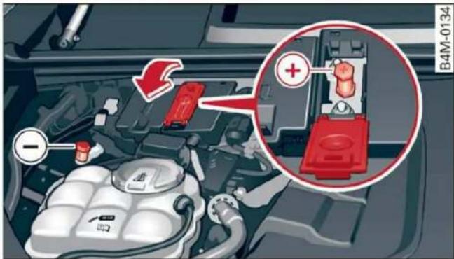
Fig. 160 Engine compartment: connectors for a charger or jump start cables
Note the safety precautions page 234, General information, !! in Battery general information on page 243 and !! .
Requirement: only use chargers with a maximum charging current of 14.8 volts. The battery cables remain connected.
The charging cable connections are located in the motor compartment. The ground point ⏻ is always located on the vehicle body.
- Switch off the ignition and all electrical equipment.
▶ Open the hood page 235.
▶ Press the release lever on the positive terminal and fold the cover upward fig. 160. - Clamp the charger terminal clamps to the jump start pins according to the instructions. (Hex head bolt under a cover +, hex head bolt on the vehicle body -).
- Insert the power cable for the charging device into the socket and switch the device on.
▶ At the end of the charging process, switch the charger off and pull the power cable out of the socket. - Remove the charging device terminal clamps.
▶ Close the cover on the positive terminal.
▶ Close the hood page 235.
! WARNING
- Never connect a charging cable or jump start cable directly to the 12 Volt vehicle battery. Only use the connections in the engine compartment page 245.
- A highly explosive mixture of gases can form when charging batteries. Only charge the battery in well-ventilated areas.
- A drained battery can freeze at temperatures around 32°F (0 °C). Do not charge or use a frozen or thawed battery. If ice forms, the battery housing can crack and battery electrolyte can leak out, which increases the risk of an explosion and chemical burns. Contact an authorized Audi dealer or authorized Audi Service Facility for more information.
- Do not connect or disconnect the charging cable while charging because this increases the risk of an explosion.
i Tips
Read all of the manufacturer's instructions for the charger before charging the battery.
Windshield washer system

natural_image
3D rendered metallic helmet or cover with a circular top and side panel (no text or symbols visible)Fig. 161 Engine compartment: washer fluid reservoir cap
Follow the safety precautions page 234, General information.
The windshield washer reservoir 🙏️ contains the cleaning solution for the windshield and the headlight washer system fig. 161, page 236. The reservoir capacity can be found in page 302.
To reduce the risk of lime scale deposits on the spray nozzles, use clean water with low amounts of calcium. Always add window cleaner to the water. When the outside temperatures are cold, an anti-freezing agent should be added to the water so that it does not freeze.
Message

Please add washer fluid
Fill the washer fluid for the windshield washer system and the headlight washer system* when the ignition is switched off.

Note
- The concentration of anti-freezing agent must be adjusted to the vehicle operating conditions and the climate. A concentration that is too high can lead to vehicle damage.
- Never add radiator anti-freeze or other additives to the washer fluid.
- Do not use a glass cleaner that contains paint solvents, because this could damage the paint.
Service interval display
The service interval display detects when your vehicle is due for service.
The service interval display works in two stages:
- Inspection or oil change reminder: after driving a certain distance, a message appears in the instrument cluster display each time the ignition is switched on or off. The remaining distance or time is displayed briefly.
- Inspection or oil change due: if your vehicle has reached an inspection or oil change interval or both intervals at the same time, the message Inspection due! or Oil change due! or Oil change and inspection due! appears briefly after switching the ignition on/off.
Checking service intervals
You can check the remaining distance or time until the next oil change or next inspection in the Infotainment system.
Applies to: MMI: Select on the home screen: VEHICLE > Settings & Service > Service intervals.
Resetting the indicator
An authorized Audi dealer or authorized Audi Service Facility will reset the service interval display after performing service.
If you have changed the oil yourself, you must reset the oil change interval.
Applies to: MMI: To reset the display, select on the home screen: VEHICLE > Settings & Service > Service intervals

Note
- Only reset the oil change indicator if the oil was changed.
– Following the service intervals is critical to maintaining the service life and value of your vehicle, especially the engine. Even if the mileage on the vehicle is low, do not exceed the time for the next service.
Wheels
Wheels and Tires
General information
▶Check your tires regularly for damage, such as punctures, cuts, cracks, and bulges. Remove foreign objects from the tire tread.
▶If driving over curbs or similar obstacles, drive slowly and approach the curb at an angle.
▶Have faulty tires or rims replaced immediately.
▶ Protect your tires from oil, grease, and fuel.
▶Mark tires before removing them so that the same running direction can be maintained if they are reinstalled.
▶Lay tires flat when storing and store them in a cool, dry location with as little exposure to light as possible.

WARNING
—Never drive faster than the maximum permitted speed for your tires. This could cause the tires to heat up too much. This increases the risk of an accident because it can cause the tire to burst.
-Always adapt your driving to the road and traffic conditions. Drive carefully and reduce your speed on icy or slippery roads. Even winter tires can lose traction on black ice.

Note
-Please note that summer and winter tires are designed for the conditions that are typical in those seasons. Audi recommends using winter tires during the winter months. Low temperatures significantly decrease the elasticity of summer tires, which affects traction and braking ability. If summer tires are used in very cold temperatures, cracks can form on the tread bars, resulting in permanent tire damage that can cause loud driving noise and unbalanced tires.
—Burnished, polished or chromed rims must not be used in winter driving conditions. The surface of the rims does not have sufficient corrosion protection for this and could be permanently damaged by road salt or similar substances.
Tire designations
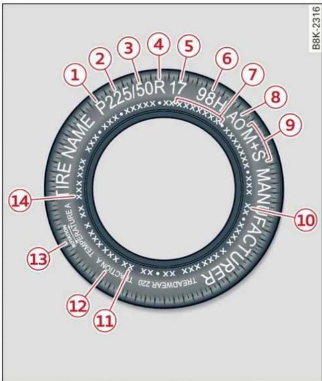
Fig. 162 Tire designations on the sidewall
① Tires for passenger vehicles (if applicable)
"P" indicates a tire for a passenger vehicle. "T" indicates a tire designated for temporary use.
② Nominal width
Nominal width of the tire between the sidewalls in millimeters. In general: the larger the number, the wider the tire.
③ Aspect ratio
Height/width ratio expressed as a percentage.
④ Tire construction
“R” indicates a radial tire.
⑤ Rim diameter
Size of the rim diameter in inches.
⑥ Load index and speed rating
The load index indicates the tire's load-carrying capacity.
The speed rating indicates the maximum permitted speed. Also see in General information on page 247.
"EXTRA LOAD", "xl" or "RF" indicates that the tire is reinforced or is an Extra Load tire.
| Speed rat-ing | Maximum permitted speed |
| P | up to 93 mph (150 km/h) |
| Q | up to 99 mph (160 km/h) |
| R | up to 106 mph (170 km/h) |
| S | up to 110 mph (180 km/h) |
| T | up to 118 mph (190 km/h) |
| U | up to 124 mph (200 km/h) |
| H | up to 130 mph (210 km/h) |
| V | up to 149 mph (240 km/h)a) |
| Z | above 149 mph (240 km/h)a) |
| W | up to 168 mph (270 km/h)a) |
| Y | up to 186 mph (300 km/h)a) |
a) For tires above 149 mph (240 km/h), tire manufacturers sometimes use the code "ZR".
⑦ US DOT number (TIN) and manufacture date
The manufacture date is listed on the tire sidewall (it may only appear on the inner side of the tire):
DOT ... 2219 ...
means, for example, that the tire was produced in the 22nd week of the year 2019.
⑧ Audi Original Tires
Audi Original equipment tires with the designation “AO” have been specially matched to your Audi. When used correctly, these tires meet the highest standards for safety and handling. An authorized Audi dealer or authorized Audi Service Facility will be able to provide you with more information.
⑨ Mud and snow capability
"M/S" or "M+S" indicates the tire is suitable for driving on mud and snow. 🚙️ indicates a winter tire.
⑩ Composition of the tire cord and materials
The number of plies indicates the number of rubberized fabric layers in the tire. In general: the more layers, the more weight a tire can carry. Tire manufacturers must also specify the materials used in the tire. These include steel, nylon, polyester and other materials.
⑪ Maximum permitted load
This number indicates the maximum load in kilograms and pounds that the tire can carry.
⑫ Uniform tire quality grade standards for treadwear, traction and temperature resistance
Treadwear, traction, and temperature ranges page 264.
⑬ Running direction
The arrows indicate the running direction of unidirectional tires. You must always follow the specified running direction ⇒ page 281.
⑭ Maximum permitted inflation pressure
This number indicates the maximum pressure to which a tire can be inflated under normal operating conditions.
Glossary of tire and loading terminology
Accessory weight
means the combined weight (in excess of those standard items which may be replaced) of automatic transmission, power steering, power brakes, power windows, power seats, radio, and heater, to the extent that these items are available as factory-installed equipment (whether installed or not).
Aspect ratio
means the ratio of the height to the width of the tire in percent. Numbers of 55 or lower indicate a low sidewall for improved steering response and better overall handling on dry pavement.
Bead
means the part of the tire that is made of steel wires, wrapped or reinforced by ply cords and that is shaped to fit the rim.
Bead separation
means a breakdown of the bond between components in the bead.
Cord
means the strands forming the plies in the tire.
Cold tire inflation pressure
means the tire pressure recommended by the vehicle manufacturer for a tire of a designated size that has not been driven for more than a couple of miles (kilometers) at low speeds in the three hour period before the tire pressure is measured or adjusted.
Curb weight
means the weight of a motor vehicle with standard equipment including the maximum capacity of fuel, oil, and coolant, air conditioning and additional weight of optional equipment.
Extra load tire
means a tire designed to operate at higher loads and at higher inflation pressures than the corresponding standard tire. Extra load tires may be identified as “XL”, “xl”, “EXTRA LOAD”, or “RF” on the sidewall.
Gross Axle Weight Rating ("GAWR")
means the load-carrying capacity of a single axle system, measured at the tire-ground interfaces.
Gross Vehicle Weight Rating ("GVWR")
means the maximum total loaded weight of the vehicle.
Groove
means the space between two adjacent tread ribs.
Load rating (code)
means the maximum load that a tire is rated to carry for a given in- flation pressure. You may not find this information on all tires be- cause it is not required by law.
Maximum load rating
means the load rating for a tire at the maximum permissible inflation pressure for that tire.
Maximum loaded vehicle weight
means the sum of:
(a) Curb weight
(b) Accessory weight
(c) Vehicle capacity weight, and
(d) Production options weight
Maximum (permissible) inflation pressure
means the maximum cold inflation pressure to which a tire may be inflated. Also called “maximum inflation pressure.”
Normal occupant weight
means 150 lbs. (68 kilograms) times the number of occupants seated in the vehicle up to the total seating capacity of your vehicle.
Occupant distribution
means distribution of occupants in a vehicle.
Outer diameter
means the overall diameter of an inflated new tire.
Overall width
means the linear distance between the exteriors of the sidewalls of an inflated tire, including elevations due to labeling, decorations, or protective bands or ribs.
Ply
means a layer of rubber-coated parallel cords.
Production options weight
means the combined weight of those installed regular production options weighing over 5 lbs.
(2.3 kg) in excess of those standard items which they replace, not previously considered in curb weight or accessory weight, including heavy duty brakes, ride levelers, roof rack, heavy duty battery, and special trim.
Radial ply tire
means a pneumatic tire in which the ply cords that extend to the beads are laid at substantially 90 degrees to the centerline of the tread.
Recommended inflation pressure
see page 250, Cold tire inflation pressure.
Reinforced tire
means a tire designed to operate at higher loads and at higher inflation pressures than the corresponding standard tire. Reinforced tires may be identified as "XL", "xl", "EXTRA LOAD", or "RF" on the sidewall.
Rim
means a metal support for a tireor a tire and tube assembly uponwhich the tire beads are seated.
Rim diameter
means nominal diameter of the bead seat. If you change your wheel size, you will have to purchase new tires to match the new rim diameter.
Rim size designation
means rim diameter and width.
Rim width
means nominal distance between rim flanges.
Sidewall
means that portion of a tire be- tween the tread and bead.
Speed rating (letter code)
means the speed at which a tire is designed to be driven for extended periods of time. The ratings range from 93 mph (150 km/h) to 186 mph (298 km/h) table on page 248. You may not find this information on all tires because it is not required by law.
The speed rating letter code,where applicable, is molded onthe tire sidewall and indicates the
maximum permissible road speeds. See also in General information on page 247 .
Tire pressure monitoring system
means a system that detects when one or more of a vehicle's tires are underinflated and illuminates a low tire pressure warning telltale.
Tread
means that portion of a tire thatcomes into contact with the road.
Tread separation
means pulling away of the tread from the tire carcass.
Treadwear indicators (TWI)
means the projections within the principal grooves designed to give a visual indication of the degrees of wear of the tread. See
⇒ page 256, Treadwear indicator for more information on measuring tire wear.
Uniform Tire Quality Grading
is a tire information system developed by the United States National Highway Traffic Safety Administration (NHTSA) that is designed to help buyers make relative comparisons among tires. The UTQG is not a safety rating and not a guarantee that a tire will last for a prescribed number of miles (kilometers) or perform in a certain way. It simply gives tire buyers additional information to combine with other considerations, such as price, brand loyalty and dealer recommendations. Under UTQG, tires are graded by the tire manufacturers in three areas: treadwear, traction, and temperature resistance. The UTQG information on the tires, molded into the sidewalls.
U.S. DOT Tire Identification Number (TIN)
This is the tire's “serial number”. It begins with the letters “DOT” and indicates that the tire meets all federal standards. The next two numbers or letters indicate the plant where it was manufactured, and the last four numbers represent the week and year of manufacture. For example,
DOT ... 2219 ...
means that the tire was producedin the 22nd week of 2019. Theother numbers are marketing co-des that may or may not be used
by the tire manufacturer. This information is used to contact consumers if a tire defect requires a recall.
Vehicle capacity weight
means the rated cargo and luggage load plus 150 lbs. (68 kilograms) times the vehicle's designated seating capacity.
Vehicle maximum load on the tire
means that load on an individual tire that is determined by distributing to each axle its share of the maximum loaded vehicle weight and dividing by two.
Vehicle normal load on the tire
means that load on an individual tire that is determined by distributing to each axle its share of the curb weight, accessory weight, and normal occupant weight (distributed in accordance with table on page 259) and dividing by two.
Occupant loading and distribution for vehicle normal load for various designated seating capacities
Refer to the tire inflation pressure label page 257, fig. 165 for the number of seating positions. Refer to the table table on page 259 for the number of people that correspond to the vehicle normal load.
New tires or wheels
Audi recommends having all work on tires or wheels performed by an authorized Audi dealer or authorized Audi Service Facility. These facilities have the proper knowledge and are equipped with the required tools and replacement parts.
▶New tires do not yet have the optimum gripping properties. Drive carefully and at moderate speeds for the first 350 miles (500 km) with new tires.
▶ Only use tires with the same design, size (rolling circumference), and as close to the same tread pattern as possible on all four wheels.
Applies to: RS models: Only use tires with the same design, size (rolling circumference), and the same tread pattern on all four wheels.
▶Do not replace tires individually. At least replace both tires on the same axle at the same time.
▶Audi recommends that you use Audi Original Tires. If you would like to use different tires, please note that the tires may perform differently even if they are the same size ⇒ ⚠️.
▶If you would like to equip your vehicle with a tire and rim combination that is different from what was installed at the factory, consult with an authorized Audi dealer or authorized Audi Service Facility before making a purchase ⇒ ⚠.
Because the spare tire* is different from the regular tires installed on the vehicle (such as winter tires or wide tires), only use the spare tire* temporarily in case of emergency and drive carefully while it is in use. It should be replaced with a regular tire as soon as possible.
All four wheels must be equipped with tires that are the same brand and have the same construction and tread pattern so that the drive system is not damaged by different tire speeds. For this reason, in case of emergency, only use a spare tire* that is the same circumference as the regular tires.

WARNING
-Do not use steel rims that are 17 inches or larger. Otherwise, damage to the vehicle and an accident could result.
-Only use tire/rim combinations and suitable wheel bolts that have been approved by Audi. Otherwise, damage to the vehicle and an accident could result.
-For technical reasons, it is not possible to use tires from other vehicles. In some cases, you cannot even use tires from the same vehicle model.
- Make sure that the tires you select have enough clearance to the vehicle. Replacement tires should not be chosen simply based on the nominal size, because tires with a different construction can differ greatly even if they are the same size. If there is not enough clearance, the tires or the vehicle can be damaged and this can reduce driving safety and increase the risk of an accident.
-Only use tires that are more than six years old when
absolutely necessary and drive carefully when doing so.
-Do not use run-flat tires on your vehicle. Using them when not permitted can lead to vehicle damage or accidents.
-If you install wheel covers on the vehicle, make sure they allow enough air circulation to cool the brake system. If they do not, this could increase the risk of an accident.
Tire wear and damage

natural_image
Close-up of a mechanical component with two red square features circled in red, no visible text or symbolsFig. 163 Tire profile: treadwear indicator
Tire wear
Check the tires regularly for wear.
-Inflation pressure that is too low or high can increase tire wear considerably.
-Driving quickly through curves, rapid acceleration, and heavy braking increase tire wear.
—Have an authorized Audi dealer or authorized Audi Service Facility check the wheel alignment if there is unusual wear.
—Have the wheels rebalanced if an imbalance is causing noticeable vibration in the steering wheel. If you do not, the tires and other vehicle components could wear more quickly.
Treadwear indicator
Original equipment tires contain treadwear indicators in the tread pattern, which are bars that are 1/16 in (1.6 mm) high and are spaced evenly around the tire perpendicular to the running direction fig. 163. The letters "TWI" or triangles on the tire sidewall indicate the location of the treadwear indicators.
The tires have reached the minimum tread depth 1) when they have worn down to the treadwear indicators. Replace the tires with new ones .
Tire rotation
Rotating the tires regularly is recommended to ensure the tires wear evenly. To rotate the tires, install the tires from the rear axle on the front axle and vice versa. This will allow the tires to have approximately the same length of service life.
For unidirectional tires, make sure the tires are installed according to the running direction indicated on the tire sidewall page 281.
Hidden damage
Damage to tires and rims can often occur in locations that are hidden. Unusual vibrations in the vehicle or pulling to one side may indicate that there is tire damage. Reduce your speed immediately. Check the tires for damage. If no damage is visible from the outside, drive slowly and carefully to the nearest authorized Audi dealer or authorized Audi Service Facility to have the vehicle inspected.

WARNING
Tread that has worn too low or uneven tread depths on the tires can reduce driving safety.
This can increase the risk of an accident because it has a negative effect on handling, driving through curves, and braking, and because it increases the risk of hydroplaning when driving through deep puddles.
Tire pressure

natural_image
Interior view of a vehicle showing front panel, side panels, and electrical connectors (no text or symbols visible)Fig. 164 Driver's side B-pillar: tire pressure label
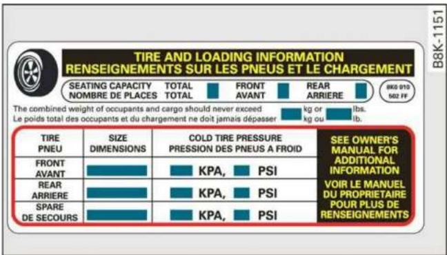
Fig. 165 Tire pressure label
The correct tire pressure for tires installed at the factory is listed on a label. The label is located on the B-pillar fig. 164, fig. 165.
Use the tire pressure specified for a normal vehicle load when the vehicle is partially loaded table
on page 259. If driving the vehicle when fully loaded, you must increase the tire pressure to the maximum specified pressure
Checking and correcting tire pressure
▶Check the tire pressure at least once per month and also check it before every long drive.
▶Always check the tire pressure when the tires are cold. Do not reduce the pressure if it increases when the tires are warm.
▶Refer to the sticker fig. 165 for the correct tire pressure.
▶ Correct the tire pressure if necessary.
▶Store the new tire pressure in the MMI page 266 or page 269.
▶Check the pressure in the spare tire*. Always maintain the maximum temperature that is specified for the tire.

WARNING
Always adapt the tire pressure to your driving style and the vehicle load.
-Overloading can lead to loss of vehicle control and increase the risk of an accident. Read and follow the important safety precautions in page 260.
—The tire must flex more if the tire pressure is too low or if the vehicle speed or load are too high. This heats the tire up too much. This increases the risk of an accident because it can cause the tire to burst and result in loss of vehicle control.
-Incorrect tire pressure increases tire wear and has a negative effect on driving and braking behavior, which increases the risk of an accident.

Note
Replace lost valve caps to reduce the risk of damage to the tire valves.

For the sake of the envi- ment
Tire pressure that is too low increases fuel consumption.
Tire pressure table
Please note that the information contained in the following table was correct at the time of printing, and the information is subject to change. If there are any differences, you should always follow the tire pressure sticker page 257, fig. 164.
Make sure that the tire designation on your tire matches the designation on the tire pressure label and the tire pressure table.
The following table lists recommended tire pressures in cold tires according to the load and the size of the tires installed.
| Model/Engine | Tire designation | Tire pressure | |||||||
| Normal load (up to three people) a) | Maximum load | ||||||||
| Front | Rear | Front | Rear | ||||||
| PSI | kPA | PSI | kPA | PSI | kPA | PSI | kPA | ||
| Q8:3.0L6-cylinder | 275/50 R20 113H | 32 | 220 | 35 | 240 | 35 | 240 | 38 | 260 |
| 285/45 R21 113H | 32 | 220 | 35 | 240 | 35 | 240 | 38 | 260 | |
| 285/45 R21 113Y | 32 | 220 | 35 | 240 | 35 | 240 | 38 | 260 | |
| 285/40 R22 110H | 35 | 240 | 38 | 260 | 39 | 270 | 42 | 290 | |
| 285/40 R22 110Y | 35 | 240 | 38 | 260 | 35 | 240 | 38 | 260 | |
| 285/35 R23 107Y | 32 | 220 | 32 | 220 | 36 | 250 | 39 | 270 | |
| RS Q8:4.0L8-cylinder b) | 295/40 ZR22 112Y155 mph (250 km/h) | 32 | 220 | 32 | 220 | 35 | 240 | 38 | 260 |
| 295/40 ZR22 112Y174 mph (280 km/h) | 38 | 260 | 38 | 260 | 41 | 280 | 44 | 300 | |
| 295/40 ZR22 112Y190 mph (305 km/h) | 41 | 280 | 41 | 280 | 46 | 320 | 49 | 340 | |
| 295/35 ZR23 108Y155 mph (250 km/h) | 36 | 250 | 36 | 250 | 39 | 270 | 42 | 290 | |
| 295/35 ZR23 108Y174 mph (280 km/h) | 44 | 300 | 44 | 300 | 46 | 320 | 49 | 340 | |
| 295/35 ZR23 108Y190 mph (305 km/h) | 46 | 320 | 46 | 320 | 48 | 330 | 49 | 340 | |
a) Two people in the front, one person in the rear
b) The tire pressure depends on the maximum permitted speed for your vehicle.

WARNING
Please note the important safety precautions regarding tire pressure page 257 and load limits page 260.
Tires and vehicle load limits
There are limits to the amount of load or weight that any vehicle and any tire can carry. A vehicle that is overloaded will not handle well and is more difficult to stop. Overloading can not only lead to loss of vehicle control, but can also damage important parts of the vehicle and can lead to sudden tire failure, including a blowout and sudden deflation that can cause the vehicle to crash.
Your safety and that of your passengers also depends on making sure that load limits are not exceeded. Vehicle load includes everybody and everything in and on the vehicle. These load limits are technically referred to as the vehicle's Gross Vehicle Weight Rating ("GVWR").
The “GVWR” includes the weight of the basic vehicle, all factory installed accessories, a full tank of fuel, oil, coolant and other fluids plus maximum load. The maximum load includes the number of passengers that the vehicle is intended to carry (“seating capacity”) with an assumed weight of 150 lbs. (68 kg) for each passenger at a designated seating position and the total weight of any luggage in the vehicle. If you tow a trailer, the weight of the trailer hitch and the tongue weight of the loaded trailer must be included as part of the vehicle load.
The Gross Axle Weight Rating ("GAWR") is the maximum load that can be applied at each of the vehicle's two axles.
The fact that there is an upper limit to your vehicle's Gross Vehicle Weight Rating means that the total weight of whatever is being carried in the vehicle (including the weight of a trailer hitch and the tongue weight of the loaded trailer) is limited. The more passengers in the vehicle or passengers who are heavier than the standard weights assumed mean that less weight can be carried as luggage.
The Gross Vehicle Weight Rating and the Gross Axle Weight Rating
are listed on the safety compliance sticker label located on the driver's side B-pillar.

WARNING
Overloading a vehicle can cause loss of vehicle control, a crash or other accident, serious personal injury, and even death.
-Carrying more weight than your vehicle was designed to carry will prevent the vehicle from handling properly and increase the risk of the loss of vehicle control.
—The brakes on a vehicle that has been overloaded may not be able to stop the vehicle within a safe distance.
—Tires on a vehicle that has been overloaded can fail suddenly, including a blowout and sudden deflation, causing loss of control and a crash.
- Always make sure that the total load being transported - including the weight of a trailer hitch and the tongue weight of a loaded trailer - does not make the vehicle heavier than the vehicle's Gross Vehicle Weight Rating.
Determining correct load limit
Use the example below to calculate the total weight of the passengers and luggage or other things that you plan to transport so that you can make sure that your vehicle will not be overloaded.
Steps for Determining Correct Load Limit
-
Locate the statement “THE COMBINED WEIGHT OF OCCUPANTS AND CARGO SHOULD NEVER EXCEED XXX KG OR XXX LBS” on your vehicle’s placard (tire inflation pressure label) → page 257, fig. 165.
-
Determine the combined weight of the driver and passengers that will be riding in your vehicle.
-
Subtract the combined weight of the driver and passengers from "XXX" kilograms or "XXX" pounds shown on the sticker page 257, fig. 165.
-
The resulting figure equals the available amount of cargo and luggage load capacity. For example, if the “XXX” amount equals 1400 lbs. and there will
be five 150 lbs. passengers in your vehicle, the amount of available cargo and luggage load capacity is 650 lbs. (1400-750 (5 x 150) = 650 lbs.)
-
Determine the combined weight of luggage and cargo being loaded on the vehicle. That weight may not safely exceed the available cargo and luggage load capacity calculated in Step 4.
-
If your vehicle will be towing a trailer, load from your trailer will be transferred to your vehicle. Consult this manual to determine how this reduces the available cargo and luggage load capacity of your vehicle.
▶Check the tire sidewall (⇒ page 248, fig. 162) to determine the designated load rating for a specific tire.
Wheel bolts and rims
Wheel bolts
Wheel bolts must be clean and loosen/tighten easily.
Rims
Rims with a bolted rim ring* or with bolted wheel covers* consist of multiple pieces. These components were bolted together using special bolts and a special procedure. You must not repair or disassemble them △.

WARNING
Wheel bolts that are tightened or repaired incorrectly can become loose and result in loss of vehicle control, which increases the risk of an accident. For the correct tightening specification, see page 281, Finishing.
- Always keep the wheel bolts and the threads in the wheel hub clean and free of grease.
- Only use wheel bolts that fit the rim.
– Always have damaged rims repaired by an authorized Audi dealer or authorized Audi Service Facility. Never repair or disassemble rims yourself, because this increases the risk of an accident.
Loose wheel warning
Applies to: vehicles with loose wheel warning
Within the limits of the system, the loose wheel warning in the instrument cluster warns you if one or more wheels are loose.
Using the ABS sensors, the loose wheel warning system compares the vibration characteristics of the individual tires. If one or more wheels are loose, it will be indicated in the instrument cluster display with the 📄 indicator light and a message. If only one wheel is affected, the location of that wheel will be indicated.
Messages
Wheel bolts loose. Please safely stop the vehicle and check all wheel bolts!
Loose wheel warning for at least one wheel ▲. Check the wheel bolts on all wheels with the wheel wrench (vehicle tool kit). Have the tightening specification checked as soon as possible with a torque wrench. Drive carefully until then. For the correct tightening specification, see page 281, Finishing.
Wheel assessment active. Please continue driving carefully
After this message appears and you have checked the wheel bolts, the assessment phase begins when the vehicle is in motion. This may take several minutes.

Loose wheel warning: malfunction! See ner's manual
There is a system malfunction. Drive immediately to an authorized Audi dealer or authorized Audi Service Facility to have the malfunction repaired.

WARNING
Wheel bolts that are tightened incorrectly can become loose and result in loss of vehicle control, which increases the risk of an accident.
- If a message appears, reduce your speed immediately and avoid any hard steering or braking maneuvers. Stop as soon as possible and check the wheel bolts.
- Check your wheels for damage. Have the damaged wheels checked and/or replaced immediately by an authorized Audi dealer or authorized Audi Service Facility.
- Under certain conditions (such as a sporty driving style, winter conditions, or unpaved roads), the message may be delayed.
- The driver is responsible for ensuring that the wheels are attached correctly.

Tips
- The loose wheel warning system can also stop working when there is an ESC malfunction.
- Using snow chains may result in a system malfunction.
Winter tires
Winter tires significantly improve the vehicle's handling when driving in winter conditions. Because of their construction (width, compound, tread pattern), summer tires provide less traction on ice and snow.
▶ Use winter tires on all four wheels.
▶ Only use winter tires that are approved for your vehicle.
▶ Please note that the maximum permitted speed may be lower with winter tires ⇒ ⚠ in General information on page 247. An authorized Audi dealer or authorized Audi Service Facility can inform you about the maximum permitted speed for your tires.
▶ Check the tire pressure after installing wheels ⇒ page 257.
The effectiveness of winter tires is reduced greatly when the tread is worn down to a depth of 0.16 in (4 mm). The characteristics of winter tires also decrease greatly as the tire ages, regardless of the remaining tread.

For the sake of the environment
Reinstall summer tires at the appropriate time, because they provide better handling when roads are free of snow and ice. Summer tires cause less road noise, tire wear, and fuel consumption.

Tips
You can also use all season tires instead of winter tires. Please note that in some countries where winter tires are required, only winter tires with the ⚠ symbol may be permitted.
Snow chains
Snow chains improve both driving and braking in winter road conditions.
▶ Only install snow chains on the rear wheels.
▶ Check and correct the seating of the snow chains after driving a few feet, if necessary. Follow the instructions from the manufacturer.
▶ Note the maximum speed of 30 mph (50 km/h). Observe the local regulations.
Use of snow chains is only permitted with certain rim/tire combinations due to technical reasons. Check with an authorized Audi dealer or authorized Audi Service Facility to see if you may use snow chains.
Use fine-mesh snow chains. They must not add more than 0.40 inch (10.5 mm) in height, including the chain lock.
You must remove the snow chains on roads without snow. Otherwise, you could impair driving ability and damage the tires.

WARNING
Using incorrect snow chains or installing snow chains incorrectly can result in loss of vehicle control, which increases the risk of an accident.

Note
- Snow chains can damage the rims and wheel covers* if the chains come into direct contact with them. Remove the wheel covers* first. Use coated snow chains.
- Do not install and use snow chains if there is a malfunction in the air suspension*, because the vehicle height will be very low. If you drive with snow chains anyway, the wheel housings and other vehicle components can be severely damaged.

Tips
When using snow chains, it may be advisable to limit the ESC page 114.
Low-profile tires
Applies to: vehicles with low-profile tires
Compared to other tire/rim combinations, low-profile tires offer a wider tread surface and a larger rim diameter with shorter tire sidewalls. This results in an agile driving style. However, it may reduce the level of comfort and increase road noise when driving on roads in poor condition.
Low-profile tires can become damaged more quickly than standard tires when driving over large bumps, potholes, manhole covers, and curbs. Therefore, it is particularly important to maintain the correct tire pressure page 257.
To reduce the risk of damage to the tires and rims, drive very carefully on poor roads.
Check your wheels regularly every 2,000 mi (3,000 km) for damage. For example, check for bulges/cracks on the tires or deformations/cracks on the rims.
After a heavy impact or damage, have the tires and rims inspected or replaced immediately by
an authorized Audi dealer or authorized Audi Service Facility.
Low-profile tires can wear out faster than standard tires.
Uniform tire quality grading
- Tread wear
- Traction AA A B C
- Temperature A B C
Quality grades can be found where applicable on the tire side wall between tread shoulder and maximum section width page 248, fig. 162.
For example: Tread wear 200, Traction AA, Temperature A.
All passenger car tires must conform to Federal Safety Requirements in addition to these grades.
Tread wear
The tread wear grade is a comparative rating based on the wear rate of the tire when tested under controlled conditions on a specified government test course.
For example, a tire graded 150 would wear one and one half (1 1/2) times as well on the government course as a tire graded 100.
The relative performance of tires depends upon the actual conditions of their use, however, and may depart significantly from the norm due to variations in driving habits, service practices and differences in road characteristics and climate.
Traction
The traction grades, from highest to lowest, are AA, A, B and C. Those grades represent the tire's ability to stop on wet pavement as measured under controlled conditions on specified government test surfaces of asphalt and concrete. A tire marked C may have poor traction performance .
Temperature
The temperature grades are A (the highest), B, and C, representing the tire's resistance to the generation of heat and its ability to dissipate
heat when tested under controlled conditions on a specified indoor laboratory test wheel.
Sustained high temperature can cause the material of the tire to degenerate and reduce tire life, and excessive temperature can lead to sudden tire failure .
The grade C corresponds to a level of performance which all passenger car tires must meet under the Federal Motor Vehicle Safety Standard No. 109. Grades B and A represent higher levels of performance on the laboratory test wheel than the minimum required by law.

WARNING
The traction grade assigned to this tire is based on straight-ahead braking traction tests, and does not include acceleration, cornering, hydroplaning or peak traction characteristics.

WARNING
The temperature grade for this tire is established for a tire that is properly inflated and not overloaded. Excessive speed, underinflation, or excessive loading, either separately or in combination, can cause heat buildup and possible tire failure.

WARNING
Temperature grades apply to tires that are properly inflated and not over or underinflated.
Tire pressure monitoring system

General notes
Each tire, including the spare (if provided), should be checked monthly when cold and inflated to the inflation pressure recommended by the vehicle manufacturer on the vehicle placard or tire inflation pressure label. (If your vehicle has tires of a different size than the size indicated on the vehicle placard or tire inflation pressure label, you should determine the proper tire inflation pressure for those tires).
As an added safety feature, your vehicle has been equipped with a tire pressure monitoring system (TPMS) that illuminates a low tire pressure tell-tale when one or more of your tires is significantly under-inflated. Accordingly, when the low tire pressure telltale illuminates, you should stop and check your tires as soon as possible, and inflate them to the proper pressure. Driving on a significantly under-inflated tire causes the tire to over-heat and can lead to tire failure. Under-inflation also reduces fuel efficiency and tire tread life, and may affect the vehicle's handling and stopping ability.
Please note that the TPMS is not a substitute for proper tire maintenance, and it is the driver's responsibility to maintain correct tire pressure, even if under-inflation has not reached the level to trigger illumination of the TPMS low tire pressure telltale.
Your vehicle has also been equipped with a TPMS malfunction indicator to indicate when the system is not operating properly. The TPMS malfunction indicator is combined with the low tire pressure telltale. When the system detects a malfunction, the telltale will flash for approximately one minute and then remain continuously illuminated. This sequence will continue upon subsequent vehicle start-ups as long as the malfunction exists.
When the malfunction indicator is illuminated, the system may not be able to detect or signal low tire pressure as intended. TPMS malfunctions may occur for a variety of reasons, including the installation of replacement or alternate tires or wheels on the vehicle that prevent the TPMS from functioning properly. Always check the TPMS malfunction telltale after replacing one or more tires or wheels on your vehicle to ensure that the replacement or alternate tires and wheels allow the TPMS to continue to function properly.
If the tire pressure monitoring indicator appears
Applies to: vehicles with Tire Pressure Monitoring System indicator
The tire pressure indicator in the instrument cluster informs you if the tire pressure is too low or if there is a system malfunction.
Using the ABS sensors, the tire pressure monitoring system compares the tire tread circumference and vibration characteristics of the individual tires. If the pressure changes in one or more tires, this is indicated in the instrument cluster display with an indicator light ⏻ and a message. If only one tire is affected, the location of that tire will be indicated.
The tire pressures must be stored again each time you change the pressures (switching between partial and full load pressure) or after changing or replacing a tire on your vehicle ⇒ page 266. The tire pressure monitoring system only monitors the tire pressure you have stored. Refer to the tire pressure label for the recommended tire pressure for your vehicle ⇒ page 257, fig. 165.
Tire tread circumference and vibration characteristics can change and cause a tire pressure warning if:
– The tire pressure in one or more tires is too low
– The tires have structural damage
- The tire was replaced or the tire pressure was changed and it was not stored page 266
– Tires that are only partially used are replaced with new tires
Indicator lights
If the ⏻ indicator light turns on, there is a loss of pressure in at least one tire ⇒ ⚠. Check the tires and replace or repair if necessary. Check and correct the pressures of all four tires and store the pressure again ⇒ page 266.
TPMS Tire pressure: malfunction! See owner's manual
If TPMS appears after switching the ignition on or while driving and the ⏻ indicator light in the instrument cluster blinks for approximately one
minute and then stays on, there is system malfunction. Try to store the correct tire pressures page 266. In some cases, you must drive for several minutes after storing the pressures until the indicator light turns off. If the indicator light does turn off or turns on again after a short period of time, drive to an authorized Audi dealer or authorized Audi Service Facility immediately to have the malfunction corrected.

WARNING
- If the tire pressure indicator appears in the display, reduce your speed immediately and avoid any hard steering or braking maneuvers. Stop as soon as possible and check the tires and their pressure.
- The driver is responsible for maintaining the correct tire pressure. You must check the tire pressure regularly.
- Under certain conditions (such as a sporty driving style, winter conditions, or unpaved roads), the tire pressure monitoring system indicator may be delayed.

Tips
- The tire pressure monitoring system can also stop working when there is an ESC malfunction.
- Using snow chains may result in a system malfunction.
- The tire pressure monitoring system in your Audi was calibrated with "Audi Original Tires" page 254. Using these tires is recommended.
Storing tire pressures
Applies to: vehicles with Tire Pressure Monitoring System indicator
If the tire pressure changes or a tire is replaced, it must be confirmed in the MMI.
▶ Before storing the tire pressures, make sure the tire pressures in all four tires meet the specified values and are adapted to the load → page 257.
▶ Switch the ignition on.
▶ Applies to: MMI: Select on the home screen:
VEHICLE > Settings & Service > Tire pressure

monitoring > Store tire pressure > Yes, store now.

Tips
Do not store the tire pressures if snow chains are installed.
If the Tire Pressure Monitoring System indicator appears

General notes
Each tire, including the spare (if provided), should be checked monthly when cold and inflated to the inflation pressure recommended by the vehicle manufacturer on the vehicle placard or tire inflation pressure label. (If your vehicle has tires of a different size than the size indicated on the vehicle placard or tire inflation pressure label, you should determine the proper tire inflation pressure for those tires).
As an added safety feature, your vehicle has been equipped with a tire pressure monitoring system (TPMS) that illuminates a low tire pressure tell-tale when one or more of your tires is significantly under-inflated. Accordingly, when the low tire pressure telltale illuminates, you should stop and check your tires as soon as possible, and inflate them to the proper pressure. Driving on a significantly under-inflated tire causes the tire to over-heat and can lead to tire failure. Under-inflation also reduces fuel efficiency and tire tread life, and may affect the vehicle's handling and stopping ability.
Please note that the TPMS is not a substitute for proper tire maintenance, and it is the driver's responsibility to maintain correct tire pressure, even if under-inflation has not reached the level to trigger illumination of the TPMS low tire pressure telltale.
Your vehicle has also been equipped with a TPMS malfunction indicator to indicate when the system is not operating properly. The TPMS malfunction indicator is combined with the low tire pressure telltale. When the system detects a malfunction, the telltale will flash for approxi-
mately one minute and then remain continuously illuminated. This sequence will continue upon subsequent vehicle start-ups as long as the malfunction exists.
When the malfunction indicator is illuminated, the system may not be able to detect or signal low tire pressure as intended. TPMS malfunctions may occur for a variety of reasons, including the installation of replacement or alternate tires or wheels on the vehicle that prevent the TPMS from functioning properly. Always check the TPMS malfunction telltale after replacing one or more tires or wheels on your vehicle to ensure that the replacement or alternate tires and wheels allow the TPMS to continue to function properly.
General information
Applies to: vehicles with tire pressure monitoring system
The tire pressure monitoring system monitors the pressure in the four tires when driving.
The system uses sensors that measure the temperature and pressure in the tires. The data is sent from these sensors to the control module by radio frequency.
The tire pressure monitoring system shows the current pressures and temperatures of the tires in the MMI while driving page 268. It also compares the current tire pressures with the stored tire pressures and gives a warning in the driver information system if the tire pressure is different from what is stored page 268.
The system does not detect if the stored tire pressures match the recommended tire pressures. You must store the tire pressures again in each of the following situations page 269:
– Each time the tire pressures change, for example when the load in the vehicle changes
- After replacing a tire
- If wheels with new wheel sensors are used

WARNING
- The tire pressure monitoring system assists the driver in monitoring tire pressures. The
driver is responsible for having the tires inflated to the correct pressure.
- Do not change the tire pressure when the temperature of the tire is extremely high. This could result in serious damage to the tire and even cause the tire to burst, increasing the risk of an accident.
- A tire with low pressure flexes more. This heats the tire up too much. This could cause the tread to separate and even cause the tire to burst, increasing the risk of an accident.
- The tire pressure monitoring system does not warn about damage or defects in the tire construction that could cause the tire to burst, for example. Inspect your tires regularly.

Tips
- If tires are replaced, the sensors and valves do not need to be removed or replaced. Only replace the valve stem and, if necessary, the valve and the wheel electronics. If you have questions, see an authorized Audi dealer or authorized Audi Service Facility.
- An incorrect display or a malfunction in the tire pressure monitoring system can occur after using the tire mobility kit*. Have the sensors replaced by an authorized Audi dealer or authorized Audi Service Facility.
- For an explanation on conformity with the FCC regulations in the United States and the Industry Canada regulations, see page 300.
Displaying tire pressures and temperatures
Applies to: vehicles with tire pressure monitoring system
Requirement: you must be driving the vehicle.
▶ Applies to MMI: Select on the home screen: VEHICLE > Settings & Service > Tire pressure monitoring > Display tire pressure.
The current tire pressures are shown in green, yellow, or red numbers:
- Green: the current tire pressure and the specified tire pressure are approximately the same.
– Yellow: the current tire pressure is lower than the specified tire pressure.
- Red: the current tire pressure is much lower than the specified tire pressure.
The specified tire pressure is the last tire pressure that was stored page 269.
Note that the tire pressure also depends on the temperature of the tire. The tire pressure increases as the engine becomes warmer while driving.

WARNING
Read and follow the important information and notes page 267.

Tips
The tire pressure or temperature is not displayed while the vehicle is stationary and in adaptation mode. Dashes --.-- are shown in place of the pressure and temperature.

Tire pressure loss
Applies to: vehicles with tire pressure monitoring system
If the ⏻ indicator light turns on, the tire pressure is too low compared to the specified pressure. Check and store the tire pressure(s) the next time it is possible page 269.

Tire Please check all tires and store preses in MMI
If the indicator light turns on and the message appears, the tire pressure has reached a critical level compared to the specified pressure. Avoid unnecessary steering and braking maneuvers. Adapt your driving style to the situation. Stop as soon as possible and check the tire(s). If it is possible to continue driving, see an authorized Audi dealer or authorized Audi Service Facility immediately and have your tire(s) repaired or replaced.

WARNING
Read and follow the important information and notes page 267.
Storing new tire pressures
Applies to: vehicles with tire pressure monitoring system
The tire pressure specifications must be stored correctly for the tire pressure monitoring system to function reliably.
It is always necessary to store the tire pressures when the tire pressures are modified, for example due to a change in load or when new sensors are installed.
▶ Before storing the tire pressures, make sure the tire pressures of all four tires meet the specified values and are adapted to the load → page 257, fig. 165. Only correct and store the pressure in tires whose temperature is approximately the same as the ambient temperature. If the temperature of the tire is higher than the ambient air temperature, the tire pressure must be increased approximately 3 PSI (0,2 bar) above the value on the sticker.
▶ Switch the ignition on.
Applies to: MMI: Select on the home screen: VEHICLE > Settings & Service > Tire pressure monitoring > Store tire pressure > Yes, store now.
▶ If the changed tire pressures are not displayed on the MMI, drive the vehicle for approximately 10 minutes so that the sensor signal from the wheels is received again.
During this adaptation phase, --.-- is displayed for the pressure and temperature and the tire pressure monitoring system is only partially available. It only provides a warning if one or more tire pressures is below the minimum permitted specified pressure.
Tire pressure: wheel change detected. Please check all tires and store pressures in MMI
If the indicator light turns on and the message appears, the system has detected that the location of the sensors has changed due to a wheel replacement, or new sensors have been installed. Store the new tire pressures.

WARNING
Read and follow the important information and notes page 267.
Malfunctions
Applies to: vehicles with tire pressure monitoring system
TPMS Tire pressure: malfunction! See owner's manual
If the TPMS indicator light appears after switching the ignition on or while driving and the ⏻ indicator light also blinks for approximately one minute and then stays on, there is system malfunction. The following are examples of situations that could cause a malfunction:
- If the message appears at the end of the adaptation phase, the system may not detect one or several of the wheel sensors necessary for pressure monitoring. This may result from one or more wheels without wheel sensors or with incompatible wheel sensors being installed.
- A wheel sensor or another component has failed.
- Using snow chains can affect the function of the system because of the shielding effect of the chains.
- The tire pressure monitoring system is not available due to a malfunction.
- Transmitters with the same frequency, such as headphones or remote-controlled devices, may cause a temporary system malfunction due to the strong electromagnetic field.
The TPMS indicator light and the message turn off once the tire pressure monitoring system is available again. If you cannot correct the malfunction and the TPMS indicator light stays on, drive immediately to an authorized Audi dealer or authorized Audi Service Facility to have the malfunction repaired.
Care and cleaning
General information
Regular, proper care helps to maintain your vehicle's value. It can also be a requirement when submitting warranty claims for corrosion damage and paint defects on the body.
The required cleaning and care products can be obtained from an authorized Audi dealer or authorized Service Facility. Read and follow the instructions for use on the packaging.

WARNING
- Using cleaning and care products incorrectly can be dangerous to your health.
- Always store cleaning and care products out of reach of children to reduce the risk of poisoning.

For the sake of the environment
– Purchase environmentally-friendly cleaning products if possible.
- Do not dispose of cleaning and care products with household trash.
Car washes
The longer that deposits such as insects, bird droppings, tree sap or road salt remain on the vehicle, the more the surface can be damaged. High temperatures such as those caused by sunlight increase the damaging effect.
Before washing, rinse off heavy deposits with plenty of water.
Stubborn deposits such as bird droppings or tree sap are best removed with plenty of water and a microfiber cloth.
Also, wash the underside of your vehicle once road salt stops being used for the season.
Pressure washers
When washing your vehicle with a pressure washer, always follow the operating instructions provided with the pressure washer. This is especially important in regard to the pressure and spraying distance. Do not aim the spray directly at the
seals on the side windows, doors, hood, luggage compartment lid, or sunroof*, or at tires, rubber hoses, insulating material, sensors*, camera lenses*, or the laser scanner*. Keep a distance of at least 16 in (40 cm).
Do not remove snow and ice with a pressure washer.
Never use cone nozzles or high pressure nozzles.
The water temperature must not be above 140 °F (60 °C).
Automatic car wash
Spray off the vehicle before washing.
Make sure that the windows and roof* are closed and the windshield wipers are off. Follow instructions from the car wash operator, especially if there are accessories attached to your vehicle.
If possible, use car washes that do not have brushes.
Washing by hand
Clean the vehicle starting from the top and working downward using a soft sponge or cleaning brush. Use solvent-free cleaning products.
Washing vehicles with matte finish paint by hand
To reduce the risk of damaging the paint when washing, first remove dust and large particles from your vehicle. Insects, grease spots, and fingerprints are best removed with a special cleaner for matte finish paint.
Apply the product using a microfiber cloth. To reduce the risk of damaging the paint surface, do not use too much pressure.
Rinse the vehicle thoroughly with water. Then clean using a neutral shampoo and a soft micro-fiber cloth.
Rinse the vehicle thoroughly again and let it air dry. Remove any water residue using a chamois.

WARNING
- To reduce the risk of accidents, only wash the vehicle when the ignition is off and follow the instructions from the car wash operator.
- To reduce the risk of cuts, protect yourself from sharp metal components when washing the underbody or the inside of the wheel housings.
- After washing the vehicle, the braking effect may be delayed due to moisture on the brake rotors or ice in the winter. This increases the risk of an accident. The brakes must be dried with a few careful brake applications.

Note
- If you wash the vehicle in an automatic car wash, you must fold the exterior mirrors in to reduce the risk of damage to the mirrors. Power folding exterior mirrors* must only be folded in and out using the power folding function.
- To reduce the risk of damage to the rims and tires, compare the width between the wheels on your vehicle with the distance between the guide rails in the car wash.
- To reduce the risk of damage, compare the height and width of your vehicle with the
height and width of the inside of the car wash.
- To reduce the risk of paint damage, do not wash the vehicle in direct sunlight.
- To reduce the risk of damage, do not wash decorative decals* with a pressure washer.
- To reduce the risk of damage to the surface, do not use insect removing sponges, kitchen sponges, or similar items.
-
When washing matte finish painted vehicle components:
-
To reduce the risk of damage to the surface, do not use polishing agents or hard wax.
- Never use protective wax. It can destroy the matte finish effect.
- Do not place any stickers or magnetic signs on vehicle components painted with matte finish paint. The paint could be damaged when the stickers or magnets are removed.

For the sake of the environment
Only wash the vehicle in facilities specially designed for that purpose. This will reduce the risk of dirty water contaminated with oil from entering the sewer system.
Cleaning and care information
When cleaning and caring for individual vehicle components, refer to the following tables. The information contained there is simply recommendations. For questions or for components that
are not listed, consult an authorized Audi dealer or authorized Audi Service Facility. Also follow the information found in ▲.
Exterior cleaning
| Component | Situation | Solution |
| Windshield wiper blades | Deposits | Soft cloth with glass cleaner ⇒ page 55 |
| Headlights/tail lights | Deposits | Soft sponge with a mild soap solutiona) |
| Sensors/camera lenses | Deposits | Sensors: soft cloth with a solvent-free cleaning solutionCamera lenses: soft cloth with an alcohol-free cleaning solution |
| Snow/ice | Hand brush/solvent-free de-icing spray | |
| Laser scanner | Deposits | Soft sponge with a mild soap solutiona) |
| Wheels | Road salt | Water |
| Brake dust | Acid-free special cleaning solution | |
| Exhaust tail pipes | Road salt | Water, cleaning solution suitable for stainless steel, if necessary |
| Decorative parts/ trim | Deposits | Mild soap solutiona) , a cleaning solution suitable for stainless steel, if necessary |
| Paint | Paint damage | Repair with touch-up paint |
| Spilled fuel | Rinse with water immediately | |
| Surface rust | Rust remover, then treat with hard wax; for questions, consult an authorized Audi dealer or authorized Audi Service Facility. | |
| Corrosion | Have it removed by an authorized Audi dealer or authorized Audi Service Facility. | |
| Water no longer beads on the surface of clean paint | Treat with hard wax (at least twice per year) | |
| No shine even though paint has been protected/paint looks poor | Treat with suitable polish; then apply paint protectant if the polish that was used does not contain any protectant | |
| Deposits such as insects, bird droppings, tree sap, and road salt | Dampen with water immediately and remove with a micro-fiber cloth | |
| Grease-based contaminants such as cosmetics or sunblock | Remove immediately with a mild soap solutiona) and a soft cloth | |
| Carbon components | Deposits | Clean the same way as painted components ⇒ page 270 |
| Decorative decals | Deposits | Soft sponge with a mild soap solutiona) |
a) Mild soap solution: maximum two tablespoons of neutral soap in 1 quart (1 liter) of water
Interior cleaning
| Component | Situation | Solution |
| Window glass | Deposits | Glass cleaner, then wipe dry |
| Decorative parts/ trim | Deposits | Mild soap solutiona) |
| Plastic parts | Deposits | Damp cloth |
| Heavier deposits | Mild soap solution a), detergent-free plastic cleaning solu-tion, if necessary | |
| Displays/instru-ment cluster | Deposits | Soft cloth with LCD cleaner; dust in the lower area of the instrument cluster can be removed using a soft brush. |
| Controls | Deposits | Soft brush, then a soft cloth with a mild soap solutiona) |
| Safety belts | Deposits | Mild soap solution a), allow to dry before letting them re-tract |
| Textiles, Artificial leather, Alcantara | Deposits adhering to the surface | Vacuum cleaner |
| Water-based deposits such as coffee, tea, blood, etc. | Absorbent cloth and mild soap solutiona) | |
| Oil-based deposits such as oil, make-up, etc. | Apply a mild soap solution a), blot away the dissolved oil or dye, treat afterward with water, if necessary | |
| Specific types of de- posits such as ink, nail polish, latex paint, shoe polish, etc. | Special stain remover, blot with absorbent material, treat afterward with mild soap solution, if necessarya) | |
| Natural leather | Fresh stains | Cotton cloth with a mild soap solutiona) |
| Water-based deposits such as coffee, tea, blood, etc. | Fresh stains: absorbent clothDried stains: stain remover suitable for leather | |
| Oil-based deposits such as oil, make-up, etc. | Fresh stains: absorbent cloth and stain remover suitable for leatherDried stains: oil cleaning spray | |
| Specific types of de- posits such as ink, nail polish, latex paint, shoe polish, etc. | Spot remover suitable for leather | |
| Care | Regularly apply conditioning cream that protects from light and penetrates into the material. Use special colored conditioning cream, if necessary. | |
| Carbon compo-nents | Deposits | Clean the same way as plastic components |
a) Mild soap solution: maximum two tablespoons of neutral soap in 1 quart (1 liter) of water

WARNING
The windshield must not be treated with water-repelling windshield coating agents. Under unfavorable conditions, such as wetness, darkness, and when the sun is low, these coatings can cause increased glare, which increases the risk of an accident. They can also cause wiper blade chatter.

Note
- Headlights and tail lights
- Never clean the headlights or tail lights with a dry cloth or sponge because the lights could be damaged. - Do not use any cleaning products that contain alcohol, because they could cause cracks to form.
- Wheels
- Never use any paint polish or other abrasive materials.
– Damage to the protective layer on the rims, such as stone chips or scratches, must be repaired immediately.
- Camera lenses
- Never use warm or hot water to remove snow or ice from the camera lens. This could cause the lens to crack.
- Never use abrasive cleaning materials or alcohol to clean the camera lens. This could cause scratches and cracks.
- Laser scanner
- Never use abrasive cleaning materials to clean the laser scanner. This could cause scratches and cracks.
- Door windows
- Remove snow and ice on windows and exterior mirrors with a plastic scraper. To reduce the risk of scratches, move the scraper only in one direction and not back and forth.
- Never remove snow or ice from door windows and mirrors using warm or hot water because this could cause cracks to form.
- To reduce the risk of damage to the rear window defogger, do not apply any stickers on the heating wires on the inside of the window.
- Decorative parts and trim
- Never use chrome care or cleaning products.
- Paint
- To reduce the risk of scratches, the vehicle must be free of dirt and dust before polishing or waxing.
- To prevent paint damage, do not polish or wax the vehicle in direct sunlight.
- To reduce the risk of paint damage, do not polish away rust spots.
- Remove cosmetics and sunscreen immediately because they could damage the paint.
- Decorative decals
- To reduce the risk of damage, do not use any rough powder or abrasive cleaning products.
- To reduce the risk of damage, do not polish decorative decals that have a matte or printed finish.
- Due to the risk of damage, do not use an ice scraper to remove snow and ice on windows with decorative decals on them.
- Displays and instrument cluster
- Make sure that the display and instrument cluster are switched off and have cooled down before cleaning. To switch off the upper and lower display, select on the MMI home screen: SETTINGS > Display & brightness > MMI > Screen cleaning.
- Displays, the instrument cluster, and the trim surrounding it must not be cleaned with dry cleaning methods because they could become scratched.
- Make sure no fluids enter the spaces between the instrument cluster and the trim, because that could cause damage.
- Controls
- Make sure that no fluids enter the controls, because this could cause damage.
- Safety belts
- Do not remove the safety belts to clean them.
- Never clean safety belts or their components with chemicals or with corrosive fluids or solvents and never allow sharp objects to come into contact with the safety belts. This could cause damage to the belt webbing.
- If there is damage to the webbing, the connections, the retractors, or the buckles, have them replaced by an authorized Audi dealer or authorized Audi Service Facility.
- Textiles, artificial leather, and Alcantara
- Never treat artificial leather or Alcantara with leather care products, solvents, floor polish, shoe polish, spot remover, or similar products.
- Have a cleaning specialist remove stubborn stains to reduce the risk of damage.
- Never use steam cleaners, brushes, hard sponges, etc. when cleaning.
- Do not turn on the seat heating* to dry the seat.
- Objects with sharp edges, such as zippers or rivets on clothing or belts, can cause damage to the surface.
- Open hook and loop fasteners, for example on clothing, can damage seat covers. Make sure hook and loop fasteners are closed.
- Natural leather
- Never treat leather with solvents, floor polish, shoe polish, spot remover or similar products.
- Objects with sharp edges, such as zippers or rivets on clothing or belts, can cause damage to the surface.
- Never use steam cleaners, brushes, hard sponges, etc. when cleaning.
- Do not turn on the seat heating* to dry the seat.
- To help prevent the leather from fading, do not leave the vehicle in direct sunlight for long periods of time. If leaving the vehicle parked for long periods of time, you should cover the leather to protect it from direct sunlight.
i Tips
- Insects are easier to remove from paint that has been freshly waxed.
- Regular waxing can prevent rust spots from forming.
- Decorative decals can age due to environmental conditions, which can result in damage such as brittleness. The color may fade if exposed to excessive sunlight.
Taking your vehicle out of service
If you would like to take your vehicle out of service for a long period of time, contact an authorized Audi dealer or authorized Audi Service Facility. They will advise you of important measures, such as corrosion protection, service, and storage procedures. Also follow the information about the vehicle battery page 243.
Emergency assistance
General information
▶ Park the vehicle as far as possible from moving traffic in the event of a breakdown. In the event of a flat tire, park the vehicle on a level surface. If you are on a steep hill, be especially careful.
▶ Set the parking brake.
▶ Switch the emergency flashers on.
▶ Have the passengers exit the vehicle. They should move to a safe place, for example behind a guard rail.

WARNING
Follow the steps given above. This is for your protection and the for the safety of others on the road.
Equipment
Vehicle tool kit, tire mobility kit, and vehicle jack
Applies to: vehicles with the vehicle tool kit, tire mobility kit, and vehicle jack

natural_image
Top-down view of a car trunk with visible rear seats and a red plastic door (no text or symbols)Fig. 166 Luggage compartment: cargo floor cover
The vehicle tool kit, vehicle jack*, tire mobility kit*, and compressor* are stored in the luggage compartment under the cargo floor cover fig. 166.
▶ Lift the cargo floor using the handle fig. 166.
Applies to: vehicles with spare tire: Turn the handle counter-clockwise and remove the spare tire.
Depending on the equipment, the vehicle tool kit* may be located under the spare tire*, under another cover, or in the tool box.

Tips
The vehicle jack* does not require any maintenance.
Tire mobility kit
Preparation
Applies to: vehicles with tire mobility kit
▶ Read and follow the important safety precautions page 276.
▶ Set the parking brake.
▶ Select the "P" position.
▶ Check if a repair with the tire mobility kit is possible page 276.
Using the tire mobility kit
Applies to: vehicles with tire mobility kit

Fig. 167 Tire: tire damage that cannot be repaired
The tire repair is only meant for temporary use. Change the damaged tire as soon as possible △.
If the tire is pierced by an object such as a nail, do not remove the object from the tire.
The tire mobility kit can be used at temperatures as low as -4 °F (-20 °C).
The tire mobility kit must not be used:
- If the tire has cuts or punctures that are larger than 0.16 in (4 mm) ① fig. 167
- If the rim is damaged ②
- If you have driven with very low tire pressure or without air in the tire ③
See an authorized Audi dealer or authorized Audi Service Facility for assistance in these situations.

WARNING
- Please note that the tire mobility kit cannot be used in all situations, and that it may only be used temporarily.
- The tire sealant must not come in contact with skin, eyes, or clothing.
- If tire sealant comes into contact with your eyes or your skin, thoroughly rinse the affected area immediately with clean water.
- Do not inhale the fumes.
- If you swallow any of the tire sealant, thoroughly rinse your mouth immediately and drink a lot of water. Do not induce vomiting. Seek medical attention immediately.
- Change your clothing immediately if it comes into contact with tire sealant.
- If an allergic reaction occurs, seek medical attention immediately.
- Keep the tire sealant away from children.
- In vehicles with a tire pressure monitoring system*, using tire sealant can result in an incorrect display or a system malfunction. Drive carefully to the nearest authorized Audi dealer or authorized Audi Service Facility.

Tips
- If sealant leaks, allow it to dry in place. You can then peel it off like a sticker.
- Note the expiration date on the sealant bottle. Replace the tire sealant at an authorized Audi dealer or authorized Audi Service Facility.
– Radio reception can be interrupted when operating the compressor.
– Follow the legal regulations that are applicable in the country where you are operating the vehicle.
Repairing tires
Applies to: vehicles with tire mobility kit
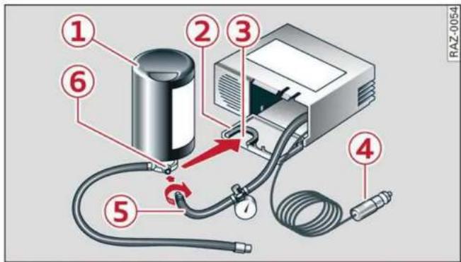
Fig. 168 Components of the tire mobility kit
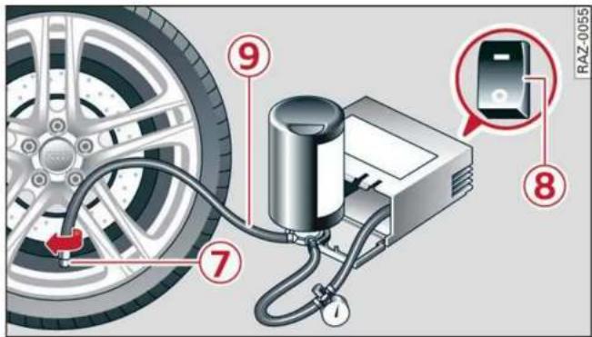
Fig. 169 Tire mobility kit connection
Requirement: the tire mobility kit must be laid out and ready for use page 276.
Setting up the tire mobility kit
▶ Open the cover ② on the compressor 1) ⇒ fig. 168.
Remove the connector ④ and pressure hose ⑤ from the housing.
- Connect the compressor pressure hose ⑤ to the flange ⑥ on the tire sealant bottle ①.
▶ Insert the sealant bottle with the flange at the bottom into the opening ③ on the compressor cover or the top side of the compressor housing.
▶ Remove the valve cap from the faulty tire.
▶ Install the filler hose ⑨ on the valve ⑦
⇒ fig. 169.
▶ Connect the plug ④ ⇒ fig. 168 to an outlet in the vehicle.
▶ Switch the ignition on.
Inflating a tire
▶ Move the switch ⑧ fig. 169 on the compressor into position I.
▶ Inflate the tire to between 29 psi (200 kPA) and 36 psi (250 kPA) and read the pressure on the gauge.
▶ If this tire pressure is not reached, remove the filler hose. Drive slowly approximately 33 feet (10 m) forward or in reverse so that the sealant can be distributed in the tire. Inflate the tire again ⇒ ⚠️.

WARNING
- Read and follow the manufacturer's safety precautions on the compressor and in the instructions on the bottle of sealant.
- If a tire pressure of 29 psi (200 kPA) cannot reached after inflating for 6 minutes, then the tire is too severely damaged. Do not continue driving.
- If the tire cannot be repaired with the tire sealant, see an authorized Audi dealer or authorized Audi Service Facility for assistance.

Tips
Do not operate the compressor for more than six minutes continuously, or it can overheat. Once the compressor has cooled, you can continue to use it.
Completing
Applies to: vehicles with tire mobility kit
▶ Affix the sticker that says "max. 50 mph (max. 80 km/h)" that is provided with the tire mobility kit within the driver's field of vision.
- Stop the vehicle after driving for about 10 minutes and check the tire pressure.
▶ If the tire pressure is lower than 19 psi (130 kPA), then the tire is too severely damaged. Do not continue driving.

WARNING
Pay attention to the following after repairing the tire: - Do not drive faster than 50 mph (80 km/h).
- Avoid hard acceleration or braking and driving fast around curves.
- The vehicle may become more difficult to control.
- If the tire is too severely damaged, see an authorized Audi dealer or authorized Audi Service Facility for assistance.

For the sake of the environment
You can give the used tire sealant bottle to an authorized Audi dealer or authorized Audi Service Facility for disposal.

Tips
Remember to obtain a new bottle of sealant from an authorized Audi dealer or authorized Audi Service Facility after repairing a tire.
Replacing wheels
Preparation
You must complete the preparation before changing a tire.
▶ Read and follow the important safety precautions page 276.
▶ Set the parking brake.
▶ Select the "P" position.
- When towing a trailer: disconnect the trailer from your vehicle.
▶ Lay out the vehicle tool kit page 276 and the spare tire page 282.
Applies to: vehicles with air suspension: Select on the home screen: VEHICLE > Settings & Service > Air suspension: wheel change.
▶ Switch the ignition off.

WARNING
- The vehicle must also be secured to prevent it from rolling when using the vehicle jack*. Use suitable objects to block the front and back of the wheel that is diagonal from the wheel with the flat tire.
- Vehicles with active roll stabilization*: Switch the ignition off because the suspension regulation could change the vehicle
height, which increases the risk of an accident.
Removing the caps

natural_image
Illustration of a car wheel with BMW logo and red capsule pins, no text or symbols presentFig. 170 Wheel: wheel bolts with caps
▶ Slide the plastic clip from the vehicle tool kit onto the cap until it engages fig. 170.
▶ Remove the cap with the plastic clip.
Anti-theft wheel bolts
Applies to: vehicles with anti-theft wheel bolts
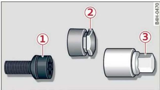
Fig. 171 Anti-theft wheel bolt with cap and adapter
You need a special adapter in the vehicle tool kit to remove the anti-theft wheel bolts.
▶ Remove the cap ②.
▶ Slide the adapter ③ all the way onto the anti-theft wheel bolt ①.
▶ Slide the wheel wrench from the vehicle tool kit all the way onto the adapter ③.
▶ Loosen the wheel bolt page 279.
i Tips
Note the code number for the wheel bolt adapter and store it in a safe place separate from the vehicle. If you need a replacement adapter, contact an authorized Audi dealer or authorized Audi Service Facility and give them the code number.
Loosening the wheel bolts

natural_image
Illustration of a car tire with a red arrow indicating a downward motion, no text or symbols present.Fig. 172 Wheel: loosening the wheel bolts
▶ Slide the wheel wrench from the vehicle tool kit all the way onto the wheel bolt 1) .
▶ Turn the wheel bolt approximately one turn to the left. To achieve the required torque, hold the end of the wheel wrench. If the wheel bolt will not loosen, press carefully on the wheel wrench with your foot. Hold onto the vehicle securely while doing this and make sure your footing is stable.
! WARNING
To reduce the risk of an accident, only loosen the wheel bolts gently one turn before raising the vehicle with the vehicle jack*.
Raising the vehicle
Applies to: vehicles with vehicle jack
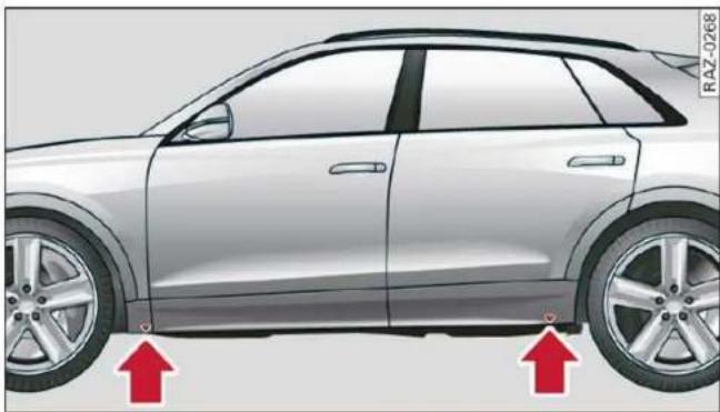
natural_image
Side view of a silver SUV with two red arrows pointing to the side of the wheel (no text or symbols present)Fig. 173 Sill panels: markings
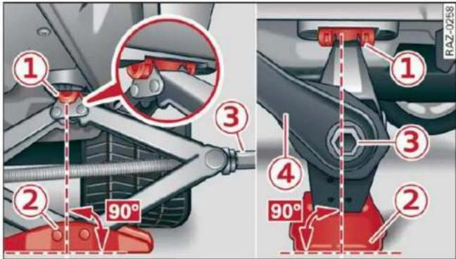
Fig. 174 Sill: positioning the vehicle jack
▶ Place the vehicle jack from the vehicle tool kit on a firm surface. Use a flat, stable support if necessary. On a slippery surface such as tile, you should use a non-slip pad such as a rubber mat ⇒ !
▶ Find the marking on the sill that is closest to the tire that will be changed fig. 173. Behind the marking, there is a lifting point on the side sill for the vehicle jack.
▶ Using the hex socket wrench ③ from the vehicle tool kit, turn the vehicle jack under the lifting point on the side sill until it is high enough that the arm ① ⇒ fig. 174 is under the designated plastic mount.
- Align the vehicle jack so the arm ① engages in the designated lifting point in the door sill and the base ② lies flat on the ground. The base ② must be directly under the mounting point ①.
▶ To lift the vehicle, position the ratchet ④ from the vehicle tool kit with the correct side on the hex socket wrench ③.
▶ Move the ratchet ④ clockwise back and forth until the wheel lifts up slightly from the ground.

WARNING
- To reduce the risk of injury, make sure no one is in the vehicle before raising it. - Make sure the vehicle jack is stable. The risk of injury is increased when the ground is slippery or soft, because the vehicle jack could slide or sink.
- Only raise your vehicle with the vehicle jack provided by the factory. If you use a vehicle jack designed for another vehicle, your vehicle could slip and cause injury.
- Position the vehicle jack only at the designated mounting points on the side sill and align the jack. Otherwise, the vehicle jack could slip and cause an injury if it does not have sufficient hold on the vehicle.
- To reduce the risk of injury, do not raise any other vehicles or other loads using the vehicle jack provided by the factory.
- Applies to: vehicles with air suspension: Changes in temperature or load can affect the height of the vehicle when stationary.
- To reduce the risk of an accident, never start the engine when the vehicle is raised.
- To reduce the risk of injury, no work should be performed under the vehicle while it is raised.

Note
Do not lift the vehicle by the sill. Position the vehicle jack only at the designated mounting points on the side sill. Otherwise, your vehicle could be damaged.
Removing and installing a wheel

natural_image
3D illustration of a car wheel with red screwdriver inserted, showing mechanical components (no text or symbols)Fig. 175 Wheel: internal hex socket to turn the wheel bolts
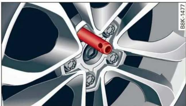
natural_image
Close-up of a car wheel rim with red plastic tube inserted, no visible text or symbolsFig. 176 Wheel: alignment pin in the top hole
Removing a wheel
Remove the top wheel bolt completely using the hex socket in the screwdriver handle from the vehicle tool kit fig. 175 and place it on a clean surface.
▶ Then install the alignment pin from the vehicle tool kit by hand in the empty wheel bolt hole fig. 176 1) .
▶ Remove the rest of the wheel bolts.
▶ Remove the wheel !. The alignment pin remains in the hole while doing this.
Installing a wheel
Read the directions on page 281 when installing unidirectional tires.
▶ Slide the wheel on over the alignment pin ⇒ ⚠️.
▶ Install the wheel bolts and tighten them gently using the hex socket.
- Remove the alignment pin and tighten the remaining wheel bolt.
- Carefully lower the vehicle using the vehicle jack*.
▶ Tighten the wheel bolts in a diagonal pattern using the wheel wrench.
The wheel bolts must be clean and loosen and tighten easily. Check the contact surfaces for the wheel and hub. Contaminants on these surfaces must be removed before installing the wheel.

WARNING
- Read and follow the important information and notes under page 254.
- Never use the hex socket in the screwdriver handle to tighten the wheel bolts. Using the hex socket will not achieve the required tightening torque, which increases the risk of an accident.

Note
When removing or installing the wheel, the rim could hit the brake rotor and damage the rotor. Work carefully and have a second person help you.
Unidirectional tires
A unidirectional tire profile is identified by arrows on the tire sidewall that point in the running direction. You must always maintain the specified running direction. This is necessary to ensure the tire's optimal performance in regard to adhesion, running noise, and friction, and to reduce the risk of hydroplaning.
To benefit fully from the advantages of the unidirectional tire design, you should replace faulty tires as soon as possible and restore the correct running direction on all of the tires.
Finishing
▶ Reinstall the caps on the wheel bolts if necessary.
- Store the vehicle tool kit in its designated place.
▶ If the removed wheel does not fit in the spare wheel well, store it securely in the luggage compartment page 79.
▶ Check the tire pressure on the installed wheel as soon as possible. - Correct the tire pressure and store it in the MMI
⇒ page 266 or ⇒ page 269.
The wheel bolt tightening specification must be 120 ft lbs (160 Nm). Have it checked as soon as possible with a torque wrench. Drive carefully until then.
▶ Have the faulty wheel replaced as quickly as possible.
Collapsible spare tire
Applies to: vehicles with collapsible spare tire
The collapsible spare tire is intended for short-term use only. Have the damaged tire checked and replaced if necessary by an authorized Audi dealer or authorized Audi Service Facility as soon as possible.
There are some restrictions on the use of the collapsible spare tire. The collapsible spare tire has been designed specifically for your type of vehicle. Do not replace it with the collapsible spare tire from another type of vehicle.
The collapsible spare tire is located in the luggage compartment under the cargo floor cover.
Requirement: the vehicle tool kit page 276 and the compressor must be laid out.
Removing
▶ Lift the cargo floor using the handle.
▶ Turn the handwheel counter-clockwise and remove it.
▶ Remove the collapsible spare tire.
You must inflate the collapsible spare tire beforehand in order to use it.
Inflating
-
Remove the valve cap from the collapsible spare tire.
▶ Tighten the compressor hose on the collapsible spare tire valve. -
Connect the compressor hose to a vehicle socket and switch it on.
▶ Let the compressor run until the specified value on the tire pressure sticker is reached ⇒ page 257, fig. 165 ⇒ !.
▶ Screw the valve cap back onto the valve.
Returning to storage
▶ To release air, turn the valve insert. See an authorized Audi dealer or authorized Audi Service Facility.
▶ Turn the valve insert back once the air has been released.
▶ Wait several hours before placing the collapsible spare tire in the spare wheel well. Only then will it fold down completely so that you can store it securely.
▶ Then screw the valve cap back onto the valve.
- Secure the collapsible spare tire with the handwheel.
▶ Fold the cargo floor cover back into place.
Snow chains
Using snow chains on the collapsible spare tire is not permitted for technical reasons.
If you have to drive with snow chains and a rear tire fails, mount the collapsible spare tire in place of a front tire. Install the snow chains on the front tire that you removed, and install that in place of the rear tire that failed.

WARNING
- Only use the collapsible spare tire in emergencies and drive very carefully, especially if it is more than six years old.
- The compressor and the hose can become very hot during operation which increases the risk of burn injuries.
- After installing a collapsible spare tire, the tire pressure must be checked as quickly as possible to reduce the risk of an accident.
- Do not drive faster than 50 mph (80 km/h) with the collapsible spare tire. Driving faster than that increases the risk of an accident.
- To reduce the risk of an accident, avoid hard acceleration or braking and driving fast around curves with the collapsible spare tire.
- Never drive using more than one collapsible spare tire, because this increases the risk of an accident.
- Normal tires or winter tires must not be mounted on the collapsible spare tire rim.
Note
The compressor must be switched off after six minutes at the most to reduce the risk of overheating. Let the compressor cool down for several minutes before using it again.
Jump starting
Preparation
You should only perform the steps that follow if you have the necessary tools and technical expertise.
If the engine does not start because the vehicle battery is drained, you can jump start your vehicle using another vehicle. Jump start cables are needed to do this.
Both vehicle batteries must have 12 V nominal voltage. The voltage capacity (Ah) of the vehicle battery that is giving power must not be less than the capacity of the drained vehicle battery.
Jump start cable
Only use a jump start cable with a large enough diameter. Note the manufacturer's specifications.
Only use a jump start cable with insulated terminal clamps.
Positive cable - usually red.
Negative cable - usually black.
! WARNING
- A drained battery can freeze at temperatures around 32°F (0 °C). If the vehicle battery is frozen, it must be thawed before connecting the jump start cables. If it is not, the risk of an explosion and chemical burns increases. After jump starting the vehicle, drive to an authorized Audi dealer or author
ized Audi Service Facility immediately to have the vehicle battery checked.
- Read the warnings when working in the engine compartment page 234.
– Handling the jump start cables incorrectly may cause the vehicle battery to explode and lead to serious injuries.
Note
Jump start cables can cause considerable damage to the vehicle electrical system if they are connected incorrectly.
i Tips
- There must be no contact between the vehicles, or else voltage could flow when connecting the positive terminal and drain the vehicle battery of the vehicle providing the jump start.
- The drained vehicle battery must be connected correctly to the electrical system.
- Switch off electrical equipment that is not needed.
Jump starting
Both jump start cables must be connected in the correct order.
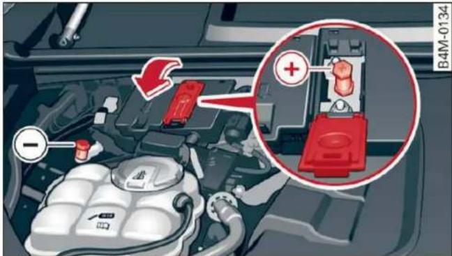
Fig. 177 Engine compartment: connectors for jump start cables or a charger

Fig. 178 Connecting the jump start cables
The jump start cable connections are located in the engine compartment.
Follow the information about the vehicle battery page 243.
Connecting the positive cable (red) to the positive terminal
▶ Open the red cover on the positive terminal
⇒ fig. 177.
1. Attach one end of the positive cable (red) to the jump-start pin ① ⇒ fig. 178 on your vehicle.
2. Attach the other end of the positive cable (red) to the positive terminal ② on the power source.
Connecting the negative cable (black) to the negative terminal
-
Attach one end of the negative cable (black) to the negative terminal ③ on the power source.
-
Attach the other end of the negative cable (black) to the jump-start pin ④ on the vehicle.
Starting the engine
▶ Start the engine in the vehicle giving the charge and let it run at idle.
▶ Now start the engine in your vehicle, which has the drained battery.
▶ If the engine does not start, stop the starting procedure after 10 seconds and then repeat it after approximately 30 seconds.
▶ Turn on the rear window defogger in your vehicle in order to reduce any voltage peaks that may occur when disconnecting the jump start cables. The headlights must be switched off.
▶ With the engines running, remove the cables in reverse order of the way they were installed.
▶ Close the red cover on the positive terminal.

WARNING
- Never connect the jump start cable directly to your vehicle battery. Only use the connections in the engine compartment.
- Do not touch the non-insulated parts of the terminal clamps. The cable must also not come into contact with vehicle components that conduct electricity when it is connected to the positive vehicle battery terminal. This can cause a short circuit.
- The plugs on the battery cells must not be opened.
- Keep ignition sources (such as open flames, burning cigarettes, etc.) away from the vehicle batteries to reduce the risk of an explosion.
- Route the jump start cables so they cannot get caught in the moving parts in the other vehicle's engine compartment.

Note
Please note that the connecting process previously described for the jump start cables is intended for when your vehicle is being jump started.

Tips
Make sure that the connected jump start cables have sufficient contact with metal.
Towing
General information
You should only perform the steps that follow if you have the necessary tools and technical expertise.
Towing requires a certain amount of practice. Audi recommends contacting a towing company to have the vehicle transported.
You should only have your vehicle towed by another vehicle when disabled in exceptional circumstances. Inexperienced drivers should not tow.
Notes on towing
When the engine is stopped, the transmission will not be sufficiently lubricated if traveling at high speeds and long distances:
- The maximum permitted towing speed is 30 mph (50 km/h).
- The maximum permitted towing distance is 30 miles (50 km).
Additional information on towing with a tow truck
The vehicle may only be towed with the front axle raised. Do not wrap any chains or cables around the brake lines.
Tow bar and towing cable
The vehicle can be towed with a tow bar or towing cable. Both drivers should be familiar with the special considerations when towing, especially when using a towing cable.
Always make sure the traction force does not exceed the permitted level and there are no shock loading conditions. There is always the risk of the coupling becoming overloaded when driving off-road.
For the most safety and security, drive with a tow bar. You should use a towing cable only if a tow
bar is not available. Use a towing cable made of synthetic elastic cable similar elastic material.

WARNING
- Towing highly increases the risk of an accident, for example from colliding with the towing vehicle.
- To reduce the risk of an accident, do not allow anyone to remain inside the vehicle when it is being transported by a tow truck or a special transporter.

Note
- If normal towing is not possible, for example if the transmission is faulty or if the towing distance is greater than 30 miles (50 km), then transport the vehicle on a special carrier.
- If the vehicle is towed by a tow truck at the axle that is not permitted, this can cause severe damage to the transmission.
- The vehicle must not be tow started for technical reasons.

Tips
- If the power supply is interrupted, then it will not be possible to move the selector lever out of the "P" position. The parking lock must be released using the emergency release before towing the vehicle page 97.
- Switch Audi pre sense* off page 150 when loading the vehicle onto a vehicle carrier, train, ship, or other type of transportation, or when towing the vehicle. This can prevent an undesired intervention from the pre sense* system.
– Follow the local legal regulations for towing.
Towing
Read and follow the important information under page 285.
Preparations
▶ Only secure the towing cable or tow bar at the designated towing loops page 286, page 287.
▶ Make sure the towing cable is not twisted. Otherwise it could disconnect from the towing loop while towing.
▶ Switch the emergency flashers on in both vehicles page 49. However, do not do this if it prohibited by law.
Towing vehicle (front)
▶ Only start to drive when the towing cable is taut.
▶ Press the brake pedal very carefully.
- Avoid sudden braking or driving maneuvers.
Vehicle being towed (rear)
▶ Make sure the ignition is switched on so that the steering wheel is not locked and so that you can use the turn signals, the horn, and the windshield wipers if needed ⇒ ⚠️.
▶ Switching it off before the vehicle has stopped may impair the function of the brake booster and power steering. You would then need to use more force to steer and brake the vehicle.
▶ Release the parking brake page 103.
▶ Select the "N" selector lever position.
▶ Make sure the towing cable is always taut.

WARNING
Never tow a vehicle using a tow bar or towing cable if the vehicle does not have electrical power.
Front towing loop

Fig. 179 Front bumper: installing the towing loop (version 1)

Fig. 180 Front bumper: installing the towing loop (version 2)
The threaded opening for the towing loop is located on the right side of the front bumper.
▶ Remove the towing loop from the vehicle tool kit page 276.
▶ Press the cap inward with brief, strong pressure fig. 179 or fig. 180. The cap will loosen from the bumper.
▶ Tighten the towing loop in the threaded opening until it stops and then tighten it with a wheel wrench.
▶ After using, place the towing loop back in the vehicle tool kit.

WARNING
If the towing loop is not tightened until it stops when installing, the threads may be pulled out when towing the vehicle and result in an accident.

Tips
Depending on the model, the shape of the cover can vary.
Rear towing loop

Fig. 181 Rear bumper: installing the towing loop (version 1)

Fig. 182 Rear bumper: installing the towing loop (version 2)
Vehicles with a towing loop
On vehicles without a factory-installed trailer hitch*, the towing loop threads are located on the right rear side of the bumper.
▶ Remove the towing loop from the vehicle tool kit page 276.
▶ Press the cap inward with brief, strong pressure fig. 181 or fig. 182. The cap will loosen from the bumper.
▶ Tighten the towing loop in the threaded opening until it stops and then tighten it with a wheel wrench.
▶ After using, place the towing loop back in the vehicle tool kit.
Vehicles with a trailer hitch\*
▶ Attach the tow bar or the towing cable to the trailer hitch.
Vehicles with a factory-installed trailer hitch* are not equipped with towing loop threads at the rear.

WARNING
If the towing loop is not tightened until it stops when installing, the threads may be pulled out when towing the vehicle and result in an accident.

Note
To reduce the risk of damaging the trailer hitch*, only use suitable tow bars that are compatible with it. If a tow bar is not available, you can use a towing cable.

Tips
Depending on the model, the shape of the cover can vary.
Fuses and bulbs
Fuses
Replacing fuses

Fig. 183 Left side of the cockpit: fuse panel cover ①, driver's footwell: fuse panel cover and clip ②
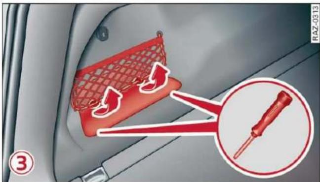
Fig. 184 Left side of the luggage compartment: fuse panel cover ③
A fuse that has blown will have metal strips that have burned through.
The fuses are located on the left front side of the cockpit ①, in the driver's footwell ②, and in the left side of the luggage compartment ③.
▶ Switch the ignition and all electrical equipment off.
▶ Check the table that follows to see which fuse belongs to the equipment.
▶ Remove the screwdriver from the vehicle tool kit page 276.
▶ Remove the appropriate cover.
▶ Remove the colored plastic clip from the fuse panel, if necessary.
Remove the clip from the fuse panel in the driver's footwell ②.
▶ Remove the fuse using the clip.
▶ Replace the blown fuse only with a fuse that has the same amp rating.
▶ Reinstall the plastic bracket.
▶ Install the cover.
Fuse color identification
| Color | Current rating in amps |
| Black | 1 |
| Gray | 2 |
| Purple | 3 |
| Pink | 4 |
| Light brown | 5 |
| Brown | 7.5 |
| Red | 10 |
| Light blue | 15 |
| Yellow | 20 |
| White or transparent | 25 |
| Light green | 30 |
| Teal | 35 |
| Orange | 40 |
! WARNING
Do not repair fuses and never replace a blown fuse with one that has a higher amp rating. This can cause damage to the electrical system and increases the risk of fire.
Note
If a new fuse burns out again shortly after you have installed it, have the electrical system checked as soon as possible by an authorized Audi dealer or authorized Audi Service Facility.

Tips
- The following table does not list fuse locations that are not used.
- Some of the equipment listed in the following tables applies only to certain model versions or certain optional equipment.
Fuse assignment - driver's footwell

Fig. 185 Driver's footwell: fuse panel with plastic clip

Fig. 186 Driver's footwell: fuse panel with plastic clip
| Fuse panel 1 (brown) | |
| No. | Equipment |
| 1 | Catalytic converter heating |
| 2 | Engine components |
| 3 | Engine components |
| 4 | Engine components |
| 5 | Brake light sensor |
| 6 | Engine components |
| 7 | Engine components |
| 8 | Engine components |
| 9 | Engine components |
| 10 | Oil pressure sensor, oil temperature sensor |
| 11 | Engine components |
| 12 | Engine components |
| 13 | Engine cooling |
| 14 | Engine control module |
| 15 | Engine sensors |
| 16 | Fuel pump |
| Fuse panel 2 (red) | |
| No. | Equipment |
| 1 | Ignition coils |
| 3 | High-voltage heating |
| 4 | Compressor |
| 5 | Engine mount |
| 6 | Windshield washer system control module |
| 7 | Instrument panel |
| 8 | Climate control system fresh air blower |
| 9 | Driver assist systems control module |
| 10 | Emergency call system |
| 11 | Engine start |
| Fuse panel 3 (black) | |
| No. | Equipment |
| 1 | Front seat heating |
| 2 | Windshield wipers |
| 3 | Left headlight electronics |
| 4 | Panoramic glass roof |
| 5 | Left front door control module |
| 6 | Sockets |
| 7 | Right rear door control module |
| 9 | Right headlight electronics |
| 10 | Windshield washer system/headlight washer system |
| 11 | Left rear door control module |
| 12 | Parking heater |
| Fuse panel 4 (brown) | |
| No. | Equipment |
| 1 | Seat ventilation, seat electronics, rearview mirror, rear climate control panel, diagnostic connector |
| 2 | Vehicle electrical system control module, gateway control module |
| 3 | Sound actuator/exhaust sound tuning |
| 4 | Transmission fluid cooling valve |
| 5 | Engine start |
| 8 | Night vision assist, active roll stabilization |
| 9 | Adaptive cruise assist, front radar |
| 10 | Exterior sound |
| 11 | Intersection assistant, driver assist systems |
| 13 | Left headlight |
| Fuse panel 5 (red) | |
| No. | Equipment |
| 1 | Anti-theft alarm system |
| 2 | Engine control module |
| 3 | Front seat electronics, lumbar support |
| 4 | Automatic transmission selector lever |
| 5 | Horn |
| 6 | Parking brake |
| 7 | Gateway control module (diagnosis) |
| 8 | Roof electronics control module |
| 9 | Drivetrain generator |
| 10 | Airbag control module |
| 11 | Electronic Stabilization Control (ESC), Anti-Lock Braking System (ABS) |
| 12 | Diagnostic connector, light/rain sensor |
| 13 | Climate control system |
| 14 | Right front door control module |
| 15 | Climate control system compressor |
Fuse assignment - left side of cockpit

Fig. 187 Left side of the cockpit: fuse panel with plastic clip
| Fuse panel 1 (black) | |
| No. | Equipment |
| 2 | Audi phone box, roof antenna |
| 3 | Climate control system, fragrance system, particulate matter sensor |
| 4 | Head-up display |
| 5 | Audi music interface, USB sockets |
| 7 | Steering column lock |
| 8 | Upper/lower display |
| 9 | Instrument cluster |
| 10 | CD/DVD player |
| 11 | Light switch, switch panels |
| 12 | Steering column electronics |
| 13 | Volume control |
| 14 | MMI Infotainment system control module |
| 15 | Steering column adjustment |
| 16 | Steering wheel heating |
Fuse assignment - luggage compartment

Fig. 188 Left side of the luggage compartment: fuse panel with plastic clip
| Fuse panel 1 (black) | |
| No. | Equipment |
| 1 | High-voltage heating, thermomanage-ment |
| 5 | Air suspension/damping |
| 6 | Automatic transmission |
| 7 | Rear seat heating, control panel for rear climate control |
| 9 | Central locking, left tail light |
| 10 | Front belt tensioner on driver's side |
| Fuse panel 1 (black) | |
| 11 | Luggage compartment lid central locking,fuel filler door, luggage compartment cover |
| 12 | Luggage compartment lid control module |
| Fuse panel 2 (red) | |
| No. | Equipment |
| 1 | Rear climate control system blower |
| 2 | Sound-amplifier |
| 3 | Exhaust treatment, sound actuator |
| 4 | Rear climate control system control panel |
| 5 | Right trailer hitch light |
| 6 | Trailer hitch positioning motor |
| 7 | Trailer hitch release |
| 8 | Left trailer hitch light |
| 9 | Trailer hitch socket |
| 10 | All wheel drive sport differential |
| 11 | Exhaust treatment |
| 12 | Driver's side rear safety belt tensioner |
| Fuse panel 3 (brown) | |
| No. | Equipment |
| 1 | Driver assist systems control module |
| 2 | Audi phone box |
| 3 | Front seat electronics, right lumbar support |
| 4 | Side assist |
| 6 | Tire pressure monitoring system |
| 8 | Parking heater radio receiver, fuel tank monitoring |
| 10 | TV tuner, data exchange and telematics control module |
| 11 | Convenience access and start authorization control module |
| 12 | Garage door opener |
| 13 | Rearview camera, peripheral cameras |
| 14 | Right tail light, comfort system |
| 15 | Passenger's side rear safety belt tensioner |
| 16 | Front belt tensioner on front passenger's side |
| Fuse panel 4(red) | |
| No. | Equipment |
| 1 | Active roll stabilization |
| 6 | Voltage converter |
| 9 | Auxiliary battery control module |
| 15 | Thermomanagement control module |
| Fuse panel 5(brown) | |
| No. | Equipment |
| Not assigned | |
Bulbs
Note
Your vehicle is equipped with maintenance-free headlights and tail lights. However, if a light bulb needs to be replaced, please contact an authorized Audi dealer or authorized Audi Service Facility.
Data privacy
Image recording
Surrounding area monitoring
Applies to: vehicles with surrounding area monitoring
Some vehicle functions require the vehicle's path to be detected and evaluated. This is done by cameras installed permanently on the vehicle that detect objects in the vehicle's surroundings (such as obstacles or guard rails). The live images from the cameras are transmitted to the applicable control module.
The camera images are transferred to the responsible control module for processing and may be stored, depending on vehicle equipment. The control module analyzes the current camera image using image evaluation software. This image evaluation software detects anonymized technical measurements, such as distances to objects. The control module evaluates these technical measurements and makes it possible for the assist systems to control the vehicle, if necessary.
Data memories
Vehicle control modules

Fig. 189 Driver's side footwell: connection port for the On Board Diagnostic System (OBD)
Your vehicle is equipped with electronic control modules for various vehicle systems such as the airbags. These vehicle control modules store data while driving normally that is required by an authorized Audi dealer or authorized Audi Service Facility for diagnosis and repair purposes. Only certain types of data are recorded for a very short period of time if a control module has detected a system event. No noises, conversations, or images will be recorded in the vehicle.
The data may include information such as the vehicle speed, the direction of travel, and information about the brake system, or also the behavior of the restraint system in the event of an accident. The stored data can be exported and downloaded with special devices, which must be connected directly to the vehicle.
On Board Diagnostic System (OBD)
There is a diagnostic connector socket in the driver's side footwell to read out the various control modules and the event data recorder. Data regarding the function and condition of the electronic control modules is stored in the event memory. Only have an authorized Audi dealer or authorized Audi Service Facility read out and delete the event memory.

WARNING
- Incorrect use of the connection port for the On Board Diagnostic System can cause malfunctions, which can then result in accidents and serious injuries.
- Only allow an authorized Audi dealer or authorized Audi Service Facility to read out the engine data.
Crash data recorder
Event Data Recorder
This vehicle is equipped with an Event Data Recorder (EDR). The main purpose of an EDR is to record, in certain crash or near crash-like situations, such as an airbag deployment or hitting a road obstacle, data that will assist in understanding how a vehicle's system performed. The EDR is designed to record data related to vehicle dynamics and safety systems for a short period of time, typically 30 seconds or less. The EDR in this vehicle is designed to record such data as:
- How various systems in your vehicle were operating;
-
Whether or not the driver and passenger safety belts were buckled/fastened;
-
How far (if at all) the driver was depressing the accelerator and/or brake pedal; and,
- How fast the vehicle was traveling.
These data can help provide a better understanding of the circumstances in which crashes and injuries occur. NOTE: EDR data are recorded by your vehicle only if a non-trivial crash situation occurs; no data are recorded by the EDR under normal driving conditions and no personal data (e.g. name, gender, age, and crash location) are recorded. However, other parties, such as law enforcement, could combine the EDR data with the type of personally identifying data routinely acquired during a crash investigation.
To read data recorded by an EDR, special equipment is required, and access to the vehicle or the EDR is needed. In addition to the vehicle manufacturer, other parties, such as law enforcement, that have the special equipment, can read the information if they have access to the vehicle or the EDR.
Assist system monitor
This vehicle is equipped with an Assist System Monitor (ASM). The ASM collects data that is not stored by the EDR in the event of an accident. The main task of the ASM is to make it possible to understand the role and the behavior of the assist systems in these accident situations. In addition to the data that the EDR stores, the ASM records data related to the assist systems starting several seconds before the accident or near-accident. The data collected by ASM depends on the equipment and may include the following information: status information of the assist systems (for example, if they are switched on or off, system events, etc.), control interventions (for example, by ESC, ABS, Audi pre sense*, etc.), and assist systems settings (such as speed settings).
Special devices and access to the vehicle or to the ASM are necessary in order to read the data from the ASM memory. In addition to the vehicle manufacturer, third parties such as law enforcement authorities can also read and analyze the stored data if they have access to the vehicle or to the ASM.
Data usage
Audi can read out the information stored in the data memories or similar data, or give this information to third parties, especially in the following situations:
- If the vehicle owner or lessee agrees
- If there is an official request from the police
- If a court or authorities request it
If legally permitted, Audi can also use the data for analysis of vehicle operation and safety performance or provide this data to third parties for research purposes.
Transmitted information
Start/Stop system
Statistical information may be recorded and transmitted to Audi in order to develop and optimize the Start/Stop system. Additional information can be found in the data privacy policy.
Privacy settings
Applies to: vehicles with Audi connect
- Applies to MMI: Select on the home screen: SETTINGS > Privacy settings.
Data is transmitted from the vehicle when using Audi connect services.
▶ To display additional information about the privacy settings and the associated symbols in the status bar, press ⓘ in the MMI.
Requirement: the ignition must be switched on.
Setting the maximum privacy settings
When the Activate privacy mode function is switched on, the data connection is deactivated or sending of data is restricted, but all safety-related, legal, or contractually required Audi connect services remain activated. The majority of the Audi connect services are deactivated.
When the function is switched off, the data connection will be available in order to use Audi connect services.
Adjusting individual privacy settings
In the MMI, you can adjust individually which data should be transmitted from the vehicle. If you switch on a data category, the data will be transmitted.
Note
You are responsible for all precautions taken for data protection, anti-virus protection, and protection against loss of data on mobile devices that are used to access the Internet through the Wi-Fi hotspot.
i Tips
- The following interfaces are not affected by changes to the privacy settings: Bluetooth, Bluetooth Low Energy (BLE), Wi-Fi, Audi smartphone interface (ASI), Near Field Communication (NFC), charging communication (high-voltage system), Electronic Toll Collect (ETC), On-Board Diagnostic System (OBD) if equipped.
- If the maximum privacy settings are switched on, your vehicle may not receive security updates and certificates for establishing an encrypted connection, depending on vehicle equipment. In order to receive security updates and certificates, switch the maximum privacy settings off for at least ten minutes every six months. Make sure that your vehicle is connected to the Internet. A symbol in the MMI status bar indicates if the required data connection is available page 21.
- If the transmission of data is limited, it will have the following effects on the exchange of data for Audi connect services and emergency calls, if equipped:
– The emergency call function will remain available without restrictions and will continue to transmit data.
- If an online roadside assistance call is initiated, no data will be transmitted, but a call will be made.
- If the Geofencing Alert, Speed Alert, and/or Valet Alert services have been activated by the key user, then they will re-
main available without restrictions and continue to transmit data.
- Stored destinations (favorites, last destinations) are only stored in the vehicle. If you allow transmission of data again, these destinations will be synchronized via the myAudi account. To prevent synchronization of destinations, delete the destinations before you allow data to be transmitted again.
Audi connect
Applies to: vehicles with Audi connect Infotainment
AUDI AG collects, uses, stores and shares your personal information, such as contact data, vehicle data, usage data, driving data and precise geolocation, in order to provide you with the products and services you have purchased or requested, and for a number of other purposes, for example, to track quality issues, to performance and safety, to meet our internal compliance or legal requirements and to market to customers and potential customers. For a more complete list of the data we collect, how we use it and with whom we share it, please visit your Audi national/sales region website at www.audi.com.
The collection, use and sharing may vary depending on your model and model year, your subscription status, or the service offering. For example, collection, use and sharing may vary between Audi connect services, if you have designated a key user, or if you are driving a model equipped with persistent data logging. Please review the complete Privacy Statement to understand our data handling practices with respect to a particular service.
You can find additional information about our data privacy practices in your MMI.
Applies to: MMI: On the home screen, select: SETTINGS > General > Legal notes > About Audi connect.
Information about our privacy practices in conjunction with the mobile Audi connect application can be found in the Application's Privacy Statement.
For additional information about the privacy practices relating to Audi connect, myAudi, or other websites, applications or online services as well as your obligations with respect to using these services, and for additional information regarding Audi connect terms and conditions, please visit your Audi national/sales region website at www.audi.com.
Accessories and technical changes
Warranty
Your vehicle is covered by various warranties:
– New Vehicle Limited Warranty
– Limited Warranty Against Corrosion Perforation
– Emissions Control System Warranties: Federal Emissions Control System Defect Warranty, Federal Emissions Performance Warranty
– Applies to: USA models: Kansas Safety Belt Limited Warranty
- Applies to: USA models: California Emissions Control Warranties: Short-term Emissions Defects Warranty, Long-term Emissions Defects Warranty, TZEV models Emissions Defects Warranty, California Emissions Performance Warranty
You can find detailed information in your Warranty & Maintenance Booklet and in the California Emissions Booklet*.
Audi Literature Shop
Service information is made available as soon as possible after a model is introduced and can be ordered in the Audi Literature Shop: http://literature.audiusa.com
Driving in other countries
Government regulations in the United States and Canada require motor vehicles to comply with emissions regulations and safety standards. Therefore, vehicles that were produced for the U.S. and Canadian markets are different from vehicles produced for other countries.
If you plan to use your vehicle outside of the United States or Canada, it is possible that:
– Fuel may have a significantly lower octane rating. Unsuitable fuels can cause engine damage.
- Proper maintenance and repair work may not be possible because special service equipment, tools, or measuring devices needed for your vehicle may not be available.
- Replacement parts may not always be available.
– Navigation systems for vehicles built for the U.S.A. and Canada will not necessarily work in Europe, and may not work in other countries.

Note
Audi is not liable for damage to the vehicle resulting from these country-specific differences.
Maintenance, repairs, and technical modifications
Note the safety precautions page 234, General information and page 280, Raising the vehicle.
General information
Due to the increasing complexity of technology in these vehicles, as well as the safety and environmental standards that apply, you can only perform a very limited amount of repairs and modifications to the vehicle yourself.
Proof of maintenance work may be required to submit a claim within the warranty period.
We recommend that you have your vehicle serviced by an authorized Audi dealer or authorized Audi Service Facility and that Audi Genuine Parts and Audi Genuine Accessories are used. This helps to ensure that your vehicle's functionality, performance, and safety are not impaired.
Maintenance and repairs
Your vehicle was designed to help keep maintenance requirements to a minimum. Some regular maintenance is required to help ensure that your vehicle runs in a safe, economical, and reliable manner. Please refer to your Warranty & Maintenance Booklet for more detailed information about vehicle maintenance.
When operating the vehicle under more extreme operating conditions, for example when outside temperatures are very low or in very dusty environments, certain maintenance should be performed between the specified intervals.
Usually maintenance and repair work requires special tools, measuring devices, and other equipment that is available to trained vehicle technicians in order to help ensure that your vehicle and all of its systems operate correctly, reliably, and safely. Performing work on the vehicle incorrectly can impair the operation and reliability of your vehicle and may void one or more of your vehicle's warranties.
Technical Modifications
Interference with electronic components, their software, the wiring, and data transfer may cause malfunctions. Because of the way electronic components are interconnected, such malfunctions can also impair systems that are not directly involved. This means that you risk both a substantial reduction in the operational safety of your vehicle and increased wear of vehicle components.
Some convenience functions, such as the convenience turn signal function, individual door opening function, and displays, can be reprogrammed using special workshop equipment. If functions are reprogrammed, the information and descriptions about these functions in this Owner's Manual may no longer apply to the changed functions. Audi recommends that an authorized Audi dealer or authorized Audi Service Facility perform and verify any reprogramming procedures.

WARNING
Maintenance procedures, repairs, or technical modifications that are performed incorrectly increase the risk of an accident and can lead to serious injuries.

WARNING
The engine compartment of any motor vehicle is a potentially dangerous area and can cause serious personal injury.
- Always use extreme caution when doing any work in the engine compartment. Always follow commonly accepted safety practices and use common sense. Never risk personal injury.
– Never perform any work in the engine compartment unless you know exactly how to
carry out the job and have the correct technical information and the correct tools.
- If you are uncertain about what to do, have the work performed by an authorized Audi dealer, an authorized Audi Service Facility, or another qualified workshop. Serious personal injury may result from improperly performed work.

Note
- Maintenance procedures, repairs or technical modifications that are performed incorrectly can cause damage to the vehicle, such as corrosion.
- If emergency repairs must be performed, take your vehicle to an authorized Audi dealer or authorized Audi Service Facility as soon as possible.
- Audi is not liable for damage to the vehicle resulting from failure to comply with these guidelines.

For the sake of the environment
- Regular maintenance can help protect the environment.
- Technical modifications to the vehicle can have a negative impact on fuel consumption and vehicle emissions.

For the sake of the environment
Certain components in your vehicle such as undeployed airbag modules, pretensioners and remote control batteries may contain Perchlorate Material – special handling may apply, See www.dtsc.ca.gov/hazardouswaste/perchlorate. When the vehicle or parts of the restraint system including airbag modules and safety belts with pretensioners are scrapped, all applicable laws and regulations must be observed. Your authorized Audi dealer is familiar with these requirements and we recommend that you have your dealer perform this service for you.

Tips
Because of your vehicle's aluminum body design, all service and repair procedures
affecting the body should be performed by an authorized Audi dealer or authorized Audi Service Facility, who will perform the work according to Audi factory specifications. Only Audi Genuine Parts are used when Audi experts perform repair or service procedures. Failure to use Audi Genuine Parts or Audi Genuine Accessories or performing repairs incorrectly may result in severe vehicle damage, such as corrosion.
Accessories and parts
Consult with an authorized Audi dealer or authorized Audi Service Facility before purchasing accessories or replacement parts. We recommend that you have your vehicle serviced by an authorized Audi dealer or authorized Audi Service Facility and that Audi Genuine Parts and Audi Genuine Accessories are used.
Audi does not endorse the use of products and accessories that it has not evaluated, even if the product is approved by a certified testing agency or government agency.

WARNING
- Installing unapproved accessories or incorrect replacement parts can cause vehicle damage and can increase the risk of an accident.
- Never attach accessories, such as telephone holders or cup holders, to the airbag covers or within the airbag deployment zone, because this increases the risk of injury if the airbag deploys.
- On vehicles that have factory-installed license plate brackets on the front of the vehicle, the brackets may only be replaced with ones that are the same size and made of the same material. Do not install any license plate brackets on the front of vehicles that do not have factory-installed brackets. Otherwise, the function of the system could be impaired.
vehicle. Otherwise, the increased electromagnetic waves can cause malfunctions in the vehicle. Observe the regulations in the country where the vehicle is being operated and the instructions from the radio equipment manufacturer.
Reporting Safety Defects Applicable to U.S.A.
If you believe that your vehicle has a defect which could cause a crash or could cause injury or death, you should immediately inform the National Highway Traffic Safety Administration (NHTSA) in addition to notifying
Audi of America, Inc.
2200 Ferdinand Porsche Drive Herndon, VA 20171
If NHTSA receives similar com- plaints, it may open an investiga- tion, and if it finds that a safety defect exists in a group of vehicles, it may order a recall and remedy campaign. However, NHTSA cannot become involved in individual problems between you, your dealer, or Audi of America, Inc.
To contact NHTSA, you may call the Vehicle Safety Hotline toll-free at 1-888-327-4236 (TTY: 1-800-424-9153); go to http://www.safercar.gov;

Note
A correctly-installed exterior antenna is required for operating radio equipment in the
or write to:
Administrator NHTSA 1200 New Jersey Ave. S.E. West Building Washington, DC 20590.
You can also obtain other information about motor vehicle safety from http://www.safercar.gov.
Applicable to Canada
If you live in Canada and you believe that your vehicle has a defect that could cause a crash, injury or death, you should immediately inform Transport Canada, Defect Investigations and Recalls. You should also notify Audi Canada.
Canadian customers who wish to report a safety-related defect to Transport Canada, Defect Investigations and Recalls, may either call Transport Canada toll-free at:
Tel.: 1-800-333-0510 or Tel.: 1-819-994-3328 (Ottawa re- gion and from other countries) TTY for hearing impaired: 1-888-675-6863
or contact Transport Canada by mail at:
Transport Canada
Motor Vehicle Safety Investigations Laboratory 80 Noel Street Gatineau, QC J8Z 0A1
For additional road safety information, please visit the Road Safety website at:
English: http://www.tc.gc.ca/eng/ motorvehiclesafety/menu.htm
French: http://www.tc.gc.ca/fra/ securiteautomobile/menu.htm
Declaration of compliance for telecom- munications equipment and electronic systems
The manufacturer is not liable for radio malfunctions that are caused by unauthorized changes to the equipment.
Equipment
The following equipment complies with FCC section 15 and RSS-Gen:
- Adaptive cruise assist*
- Remote control key
- Cell phone package*
- Garage door opener (HomeLink)*
- Intersection assistant*
- Side assist*
- Exit warning*
– Rear cross traffic assist* - Wi-Fi hotspot*
FCC Part 15.19
This device complies with part 15 of the FCC Rules. Operation is subject to the following two conditions: (1) This device may not cause harmful interference, and (2) this device must accept any interference received, including interference that may cause undesired operation.
FCC Part 15.21
Changes or modifications not expressly approved by the party responsible for compliance could void the user's authority to operate the equipment.
RSS-Gen
This device complies with Industry Canada's licence-exempt RSSs. Operation is subject to the following two conditions:
(1) This device may not cause interference; and
(2) This device must accept any interference, including interference that may cause undesired operation of the device.
Long Range Radar\* – Additional declarations of compliance
Radiofrequency radiation exposure Information: This equipment complies with FCC and IC radiation exposure limits set forth for an uncontrolled environment. This equipment should be installed and operated with minimum distance of 20 cm between the radiator and your body. This transmitter must not be co-located or operating in conjunction with any other antenna or transmitter.
Technical data
Identification data
Vehicle data label

Fig. 190 Vehicle identification label
The vehicle identification label fig. 190 is located in the luggage compartment under the cargo floor cover.
The vehicle identification label information can also be found in the Warranty & Maintenance booklet.
Vehicle data
Dimensions
| Length (in (mm)) | Width (in (mm)) | Width across the mirrors (in (mm)) | Height at curb weight (in (mm)) | |
| Q8 | 196.3 (4,986) | 78.5 (1,995) | 86.2 (2,190) | 67.1 (1,705) |
Capacities
| Approximate capacities | |
| Fuel tank | 22.5 gal (85 L) |
| Windshield and headlight washer system* | 6.3 qt (6.0 L) |
The sticker contains the following vehicle data:
① Vehicle Identification Number (VIN)
② Vehicle type, engine output, transmission
③ Engine and transmission codes
④ Paint and interior codes
⑤ Optional equipment numbers
Vehicle identification number (VIN)
The VIN is located in the following areas:
- Applies to: MMI: Select on the home screen: VEHICLE > Settings & Service > Vehicle information.
- On the vehicle identification label
- At the front behind the windshield
- Under the carpet under the right front seat
Notes about technical data
The values may vary based on special equipment as well as market-specific equipment and measuring methods.
Please note that the specifications listed in the vehicle documentation always take precedence.
i Tips
Any technical data that is missing was not available at the time of printing.
Weights

Fig. 191 Safety certificate
Gross Vehicle Weight Rating (GVWR)
The maximum permitted total weight ① of the vehicle is listed on the safety certificate on the side area of the door or on the driver's door pillar.
Gross Axle Weight Rating (GAWR)
The maximum permitted load on the front axle ② or the rear axle ③ is listed on the safety certificate on the side area of the door or on the driver's door pillar.
Load
The maximum permitted load is listed on the tire pressure label on the driver's door pillar.
Roof load
The maximum permissible roof load is 220 lbs (100 kg).
Trailer load
| Trailer with brakes up to 12% incline | Tongue weight on trailer ball hitch | |
| Q8 | 7,700 lbs (3,500 kg) | 770 lbs (350 kg) |
A
A/C cooling mode 88
Acceleration measurement 128
Accelerator pedal 96
also refer to Accelerator pedal 96
Accessories 299
Active lane assist refer to Lane departure warning ..... 145
refer to Lane guidance 145
Adaptive cruise assist 135
Cleaning sensors 271
Predictive control 134
Adaptive dampers 109
Adaptive speed assist refer to Adaptive cruise assist .... 135
Adjusting the air distribution 88
Adjusting the brightness 51
Adjusting the sound 226
Adjusting the temperature 88
Adjusting the vents 90
Adjusting the volume 28
Adjusting the volume (announcements) .... 226
Adjusting the welcome sound 226
Airbag system 68
Air pressure Tire Pressure Monitoring System ..... 267
Air suspension 109
Alarm system refer to Anti-theft alarm system .... 34
Alignment pin (changing the wheel) ..... 276
All-weather lights 47
All-wheel steering 111
All season tires 263
All wheel drive refer to quattro.... 112
Amazon Alexa integration Media playback 215
Operation 27
AMI refer to Audi music interface ..... 215
Android Auto refer to Audi smartphone interface ..... 224
Anti-freeze Windshield washer system .... 245
Anti-lock braking system 113
Anti-Slip Regulation 113
Anti-theft alarm system 34
Anti-theft wheel bolts 279
Apple CarPlay refer to Audi smartphone interface ..... 224
Aspect ratio (video) 218, 220
ASR refer to Anti-Slip Regulation .... 113
Audi adaptive light 47
Audi connect refer to connect.... 179
Audi connect Remote & Control refer to Vehicle control services ..... 181
Audi drive select 108
Audi music interface 215
Audio files 216
Audi phone box 168
Audi pre sense .... 146 Messages .... 150
Audi pre sense front 147
Audi side assist refer to Side assist .... 151
Audi smartphone interface 224 Legal information 228
Audi virtual cockpit refer to Instrument cluster .... 11
AUTO Automatic headlights .... 47 Climate control system .... 88
Auto Lock (central locking) 31
Automatic climate control system refer to Climate control system 87
Automatic luggage compartment lid .... 39, 40
Automatic transmission....94 Parking lock emergency release....97
Automatic wipe/wash system 53
Average consumption 15
Average speed 15
B
Bag hooks 79
Battery Charging (12 Volt vehicle battery) ..... 245
Vehicle battery (12 Volt) 243
Winter operation (12 Volt vehicle battery) . 243
Blinds
refer to Panoramic glass roof 43
Block route 196
Blower 88
Bluetooth
Audio player 213
Connecting a cell phone 166
Deleting a device 228
Device overview 227
Disconnecting a device 228
Displaying profiles 228
Searching for a device 228
Selecting a device 228
Specifying a favorite 228
Boost 14
Boost pressure indicator 14
Brake fluid
Checking the brake fluid level 242
Brakes 101
Brake assist.... 113
Brake fluid 242
Emergency braking function ..... 104
Hot 105
New brake pads 102
Break-in security feature 34
Breaking in
New brake pads 102
New tires 254
Browser
refer to Media center 217
Bulb replacement 292
Business address 197
C
California Proposition 65 Warning ..... 234
Battery specific 243
Call list 170, 172
Cameras 120
Locations 121
Capacities
Fuel tank 302
Washer fluid reservoir 302
Cargo floor 84
Cargo mat 83
Cargo net 82
Car key 35
Car phone
Serial number (IMEI) 176
Switching on 176
Car wash 270
Catalytic converter 233
Cell phone
refer to Telephone 166
Cell phone compartment
refer to Audi phone box 168
Central locking 31
Auto Lock 31
Convenience key 36
Convenience opening and closing ..... 42
Luggage compartment lid 38
Mechanically unlocking and locking ..... 34
Messages 33
Remote control key 36
Setting 32
Vehicle key 36
Central locking switch 33
Ceramic brakes 102
Certification 300
Changing light bulbs 292
Charging
refer to Power sources 78
Charging the battery (mobile devices). 168, 215
Child safety lock
Climate control system controls in the rear. 41
Power windows 41
Rear doors 41
Child safety seats 72
Securing to the top tether anchor ..... 76
Securing with a safety belt 75
Securing with LATCH 74
Cleaning 270
Cleaning Alcantara 273
Cleaning artificial leather 273
Cleaning carbon components ..... 272, 273
Cleaning controls 273
Cleaning decorative parts/trim 272
Cleaning exhaust tail pipes 272
Cleaning plastic parts 272
Cleaning textiles 273
Climate control system 87
Climate control system controls in the rear
Child safety lock 41
Closing
Automatic luggage compartment lid ..... 39
Convenience closing 42
Hood 235
Luggage compartment lid 38
Luggage compartment lid with foot motion . 40
Panoramic glass roof 43
Sunshade (roof) 43
Sunshade (windows) 41
Windows 41
Closing aid (power closing doors) 31
Cockpit dimming 51
Collapsible tire refer to Collapsible spare tire ..... 282
Combustion engine 99
Coming home/Leaving home refer to Entry/exit lighting 49
Compartments 79
Compass in the mirror 56
Compliance 300
Configuration wizard 19
connect 179
Data plans 184
Data Privacy 295
Emergency call 185
Infotainment 179
Infotainment services 180
Online roadside assistance 186
Vehicle control services 181
Connected devices Device overview 227
Connections refer to Media 212, 216
Consumer information 297
Consumption Reducing 99
Consumption (fuel) 15
Contacts Add destination.... 197
Importing and exporting 177
Memory capacity 177
Opening (business card) 171
Updating in the MMI 177
Convenience key 31
Convenience closing 42
also refer to Vehicle key 35
Convenience opening and closing Windows or panoramic glass roof ..... 42
Coolant temperature display 13
Cooling mode 88
Cooling system Adding coolant 241
Checking the coolant level 241
Coolant 240
Cornering light 47
Cross traffic assist (intersection assistant) .. 154
Cruise control system 131
Cup holders 78
Current consumption 15
D
Data plans 184
Data Privacy 295
Date.... 15 Setting.... 226
Daytime running lights 47
Declaration of compliance 300
DEF (instrument cluster) 11
Demo mode refer to Presentation mode .... 201
Destination on the map 193
Details 192
Determining correct load limit 261
Digital compass 56
Dimensions 302
Dimming the exterior mirrors 52
Dimming the rearview mirror 52
Directory Settings.... 177 also refer to Contacts.... 171
Display Cleaning 272
Disposal 297
Distance 15
Distance warning 144
Doors Child safety lock .... 41 Door contact switch .... 50
Mechanically unlocking and locking ..... 34
Power closing/closing aid 31
Driver information system 12
Drives
refer to Media 212, 216
Drive select
refer to Audi drive select 108
Drive system 99,101
Audi drive select 109
Driving down hills 105
Driving program 95,143
Driving through water 106
Driving time 15
Driving tips
Driving through water 106
Efficient driving 99
Offroad driving 105
Uphill and downhill.... 105
Driving track 104
Driving up hills 105
DVD drive (media drives) 213
E
Message options 175
Settings 175
EDL
refer to Electronic Differential Lock ..... 113
EDR
Event Data Recorder 293
Efficiency assist 132
Electrical system 242
Electromechanical parking brake ..... 103
Electronic Differential Lock 113
Electronic immobilizer 36
Electronic Stabilization Control ..... 113
Embedded SIM card 180
Emergency assist 155
Emergency assistance 276
Emergency braking function 104
Emergency call 172, 185
Emergency flashers 49
Emergency mode 98
Emergency operation
Doors 34
Luggage compartment lid 40
Panoramic glass roof 43
Emissions control system 233
Energy consumers 16
Energy management 99
Engine
Breaking in 99
Coolant 240
Emergency stop 92
Jump starting 283
Start/Stop system 100
Starting/stopping 92
Engine compartment
Opening and closing the hood 235
Overview 236
Safety precautions 234
Engine data
refer to Sport displays 15
Engine oil
Adding 236
Changing 239
Checking oil level 236
Consumption 236
Indicator light 236
Replacement interval 246
Temperature display 14
Engine sound
Audi drive select 109
Engine start system 93
Engine stop
refer to Start/Stop system 100
Entry/exit lighting 49
Entry assistance 61
also refer to Exit assistance 61
Environment
Unleaded gasoline 230
eSIM
refer to Embedded SIM card 180
Event Data Recorder (EDR) 293
Exit assistance 61
Exit warning 153
Exterior lighting 47
Exterior mirrors 51
Folding settings 32
External voice operation 27
F
Factory default settings
Multi Media Interface 227
Fast forwarding and rewinding (media file) . 216
Fast forwarding (media files) 216
Fast route 189
Favorites
Bluetooth 228
Navigation 191
Telephone 171
Federal Communications Commission (FCC) . 300
File formats (media drives) 222
Fixture set 83
Fog (windows) 89
Folding the rear seats 81
Footwell temperature 90
For the sake of the environment
Disposing of engine oil 239
Fueling 231
Leaks 235
Fragrance 89,90
Free text search
Media 220
Radio 206
also refer to Intelligent search ..... 189
Freeze protection
Coolant 240
Front center armrest 61
Front collision warning
refer to Audi pre sense front ..... 146
Front passenger's seat adjustment
Front 61
Rear 61
Front wiper blades
Changing 54
Cleaning 54
Fuel 230
Additives 231
Current consumption 15
Fuel display 11
Fuel tank capacity 302
Gasoline 230
Reducing fuel consumption 99
Fueling
Fuel filler door emergency release ..... 233
Fuel tank capacity 302
G
Gasoline mixture 230
GAWR
refer to Gross Axle Weight Rating (GAWR) . 303
Gears 94
Glossary of tire and loading terminology . . . 250
Glove compartment 79
G meter
refer to Sport displays 15
Gross Axle Weight Rating (GAWR) ..... 303
Gross Vehicle Weight Rating (GVWR) ..... 303
GVWR
refer to Gross Vehicle Weight
Rating (GVWR) 303
H
Handsfree 167
Hands Free Profile 167
Head-up display
Adjusting 25
Adjusting the brightness 51
Operating 25
Headlight range control 47
Headlights
Cleaning 271
Headlight range control 47
Washer system 53
Head restraints
Adjusting 63
Removing and installing 63
Heated rear window 89
Heated steering wheel 90
Heating 87
HFP
refer to Hands Free Profile 166
High beams High beam assistant 48
Highway lights 47
Hill descent assist 106
Hill descent control 105
Hill hold assist 94
Home refer to Home address 197
Home address 197
HomeLink refer to Garage door opener 43
Home screen 18
Horn 6
Hotspot refer to Wi-Fi 183
I
Ignition Switching on and off 92
Imbalance (wheels) 256
Immobilizer refer to Electronic immobilizer .... 35
Inclinometer 105
Indicator lights 7
Inspection interval 246
Instrument cluster 11
Adjusting the layout 12
Cleaning 272
Engine code 229
Failure 11
On-board computer 15
Operating 12
Personal profile 11
Service interval display 246
Software information 229
Switching tabs 12
Switching the view 12
Vehicle functions 15
Version information 229
Instrument illumination 51
Integrated assistance 19
Intelligent search Navigation.... 189
Interior lighting 50, 51
Interior monitoring 34
Intermittent mode (windshield wipers) ..... 53
International travel 184
Internet refer to connect.... 179
Internet radio refer to Online radio 208
Intersection assistant 154
Ionizer 89
iPhone refer to Audi music interface ..... 215
J
Jump starting 283
K
Key 31,35
Convenience opening and closing ..... 42
Key replacement 35
Mechanical key 35
Not recognized 93
PANIC key 35
Replacing the battery 37
Unlocking and locking 36
Vehicle code 35
Key user 30
Kick-down 96
L
Lane assist refer to Lane departure warning ..... 145
refer to Lane guidance 145
Lane departure warning 145
Cleaning the camera area 271
Lane guidance 139
Lap timer 127
Evaluating 128
Starting 127
Laser scanner 120
Cleaning 272
LATCH (securing child safety seats) 74
Launch Control 97
Leather care and cleaning 273
Legal information
License subscriptions 228
Software information 228
Software licenses 228
Version information 228
License plate bracket 299
Lifting points (vehicle jack) 280
Light/rain sensor
Headlights 47
Intermittent mode (windshield wipers) .... 53
Lighting
Exterior 47
Interior 50
Lights 47
Listening to music
refer to Media 212, 216
Load 303
Locking and unlocking
By remote control 36
Using the lock cylinder 34
With the convenience key 36
Low beam headlights 47
Lowering the rear of the vehicle 81
Luggage compartment 79
Cargo floor 84
Cover 80
Increasing the size 81
also refer to Luggage compartment ..... 79
Luggage compartment lid
Closing button 39
General information 37
Mechanically unlocking 40
Opening and closing 38
Opening and closing with foot motion ..... 40
Power opening and closing 39
Lumbar support 59
M
Maintenance 297
Maintenance intervals 246
Malfunction Indicator Lamp (MIL) 233
Manual shifting 96
Map
Changing the scale 193
Display 195
Operating 194
Setting the destination 193
MAP
refer to Message Access Profile ..... 173
Map preview 192
Map update 199
Online 199
SD card/USB connection 199
Massage function 59
Front 60
Mechanical key 35
Media 212,216
Drives 212
Supported formats 222
Media center 217
Memory card
SD card reader (MMI) 212
Supported types and formats 222
Memory function 67
Menu language
refer to Setting the language 226
Message Access Profile 173
Messages 173
Mild hybrid drive system 99
Mirror compass 56
Mirrors
Adjusting exterior mirrors 51
Dimming 52
Vanity mirror 53
MMI
refer to Multi Media Interface ..... 19
Mobile device
refer to Telephone 166
Mobile phone network
Connection settings 177
Mountain passes 105
Mountain roads 105
Multifunction steering wheel
Buttons 12,28
Operating 12
Programming buttons 28
Voice recognition system 26
Multi Media Interface 19
Menus and symbols 20
Operating 17,20
Switching the displays on or off 19
Muting (mute) 28
myAudi 29
Automatic login 29
myAudi navigation 188, 192
N
Narrow areas 143
Natural leather care and cleaning 273
Navigation 188
Better route 200
Calling 192
Changing the scale 192
also refer to Map 194
Navigation database
Version information 228
Navigation (instrument cluster) 195
NHTSA 299
Night vision assist 129
Cleaning the camera 271
Notification center 21
O
Octane rating (gasoline) 230
Odometer 14
Resetting 14
Office address
refer to Business address 197
Offroad
refer to Offroad driving 105
Offroad driving 105
OFF (climate control system) 88
Oil
refer to Engine oil 236
On-board computer 15
On Board Diagnostic System (OBD) ... 233, 293
Online destination
refer to Online Points of Interest ..... 191
Online map
refer to Satellite map 198
Online media 214
Online Points of Interest 191
Online radio 208
also refer to Online radio 208
Online roadside assistance 186
Online services
refer to connect 179
Online system update 227
Online traffic information 201
Opening 31
Automatic luggage compartment lid ..... 39
Convenience opening 42
Luggage compartment lid 38
Luggage compartment lid with foot motion . 40
Panoramic glass roof 43
Sunshade (roof) 43
Sunshade (windows) 41
Windows 41
Opening and closing
refer to Unlocking and locking ..... 31, 36
Operating
Head-up display 25
Instrument cluster 12
Multifunction steering wheel 12
Multi Media Interface 17,20
Text input 23
Touch display 17
Voice recognition system 26
Optional equipment number 302
Options
Media 220
Navigation 201
Radio 209
Overview (cockpit) 6
P
Paint code 302
Paint damage 272
Paint number 302
Panic button 35
PANIC button 35
Panic function 35
Panoramic glass roof 43
Convenience opening and closing ..... 42
Emergency closing 43
Quick opening 43
Parental control
DVD 221
Parking aid 157
Adjusting the volume 158
Automatic activation 157
Cleaning sensors/camera 271
Deactivating rear cross-traffic assist ..... 164
Parking aid plus 157
Peripheral cameras 159
Rearview camera 159
Trailer view 161
Parking and maneuvering 157
Parking brake
refer to Electromechanical parking brake. 103
Parking lights 47
Parking lock emergency release 97
Partition net 82
Pass-through 82
Password
myAudi automatic login 29
Paths 18
Pause (media files) 216
Pedals 96
Pedestrian detection 129
Perchlorate 297
Performance/torque display
refer to Sport displays 15
Peripheral cameras 159
Personal route assistance 196
Phone
Answering/ending a call 172
Connecting a second mobile device ..... 167
Disconnecting a mobile device ..... 168
Settings 176
Phonebook
refer to Contacts 171
Playback (media) 216
Podcast
refer to Online radio 208
POI 191
Point of interest
refer to Online Points of Interest ..... 191
Polishing 272
Pollutant filter 87
Power closing (doors) 31
Power sources 78,215
Power window malfunction 41
Power windows 41
Malfunction 41,42
Predictive control 134
Predictive messages 96,133
pre sense
refer to Audi pre sense 146
Presentation mode 203
Presets
Radio 206
Presets list
refer to Presets 206
Pressure
Tire pressure monitoring system ..... 266
Tires 257
Progressive steering
Protecting .....
Pyrotechnic elements

quattro 112
Selective wheel torque control ..... 113
R
Radio 204
Radio text 207
Station list 204
Radio communications equipment ..... 299
Radio equipment 299
Radio Standards Specification (RSS) ..... 300
Rail carrier 110
Rain/light sensor
Headlights 47
Intermittent mode (windshield wipers) .... 53
Range 15
Reading lights 50
Rear cross-traffic assist 164
Rear lid
refer to Luggage compartment lid ..... 38
Rear lowering 81
Rear seats 61
Rearview camera 159
Rear window defogger 89
Rear wiper blades
Changing 55
Cleaning 55
REAR (climate control system) 88
Reception range 204
Recirculation mode 89
Recuperation 16
Refueling 231
Remote control
Remote control key 35
Convenience opening and closing ..... 42
Key replacement 35
LED 37
Replacing the battery 37
Unlocking and locking 36
also refer to Vehicle key 35
Removing the caps (wheel bolts) 279
Repairs 297
Repeat 218
Replacement key 35
Replacement parts 299
Replacing fuses 288
Reporting Safety Defects 299
Rewinding (media files) 216
Rims 262
Cleaning 272
Road carrier 110
Roof refer to Panoramic glass roof ..... 43
Roof load 303
Roof rack 84
also refer to Roof rack 84
Route guidance Stopping 193
also refer to Navigation 188
Running direction (tires) 281
S
Safety belts 64
Cleaning 273
Locking 75
Securing child safety seats 75
Satellite map 198
Saving fuel Energy consumers .... 16
Recuperation 16
Screen refer to Touch display 17
Screwdriver 276
SD card reader (MMI) 212
Search area (POI) 191
Search function refer to Free text search ..... 220
Seat heating 89
Seats
Adjusting the front seats 59
Adjusting the rear seats 61
Cleaning 273
Folding 81
Front passenger's seat adjustment ..... 61
Head restraints 63
Massage function 59
Memory function 67
Resetting the position 61
Storing a seat profile 67
Seat ventilation 89
Selecting a source (media) 216
Selector lever 94
Self-learning navigation refer to Personal route assistance ..... 196
Sensors Coverage areas.... 120
Locations 121
Service interval display 246
Setting measurement units 226
Settings 226
Announcements and tones 226
Bluetooth 227
Date and time 226
Language 226
Measurement units 226
Media 221
Navigation 201
Radio 210
Sound 226
System 226
Time zone 226
Wi-Fi hotspot 183
Setting the language 226
Setting the time 226
Shade Rear window 53
Shift light indicator 14
Shift paddles 96
Ship carrier 110
Shortcut refer to Shortcuts 22
Shortcuts 22
Shuffle 218
also refer to Shuffle 218
Side assist 151
Cleaning sensors 271
SIM card 180
SiriusXM alert notifications 207
Sliding/tilting sunroof refer to Panoramic glass roof ..... 43
Smart favorites 207
Smartphone Wireless charging .... 168 also refer to Telephone .... 166
Snow chains 263
Socket 78
Software Update.... 227
Software information Legal information.... 228
Software version (MMI) Version information.... 228
Sound refer to Adjusting the sound ..... 226
Speed limit information refer to Traffic sign recognition ..... 124
Speed limits refer to Traffic sign recognition ..... 124
Speedometer 11
Speed warning system 124
Sport differential 112
Sport displays 15
Sporty driving 104
Start/Stop system.... 100 Messages.... 101 Switching off and on.... 100
Starting to drive 93
Starting (engine) 100
Steering.... 111 Audi drive select.... 109 also refer to Steering.... 111
Steering lock 92,111
Steering wheel Adjusting 62 Shift paddles 96 Steering wheel heating 90 also refer to Multifunction steering wheel.. 12
Steps for determining correct load limit . . . 261 Stopover (navigation) ..... 193 Stopping (engine) ..... 100
Storage 79
Storage compartment 79
Storage net 79
Stored stations refer to Presets 206
Streaming refer to Online media 214
Subtitles (DVD) 220
Sunshade Rear window.... 53 Roof.... 43 also refer to Panoramic glass roof.... 43
Sunshade (windows) Opening and closing ..... 41 Rear side windows ..... 42
Sun visors 53
Suspension.... 109 Audi drive select.... 109
Swap call 173
Swerve assist 149
Symbols Navigation.... 194 Traffic.... 200 also refer to Indicator lights.... 7
SYNC (climate control system) 88 System settings 226
T
Tachometer.... 11, 13
Tail lights Cleaning 271
Technical data 302
Technical modifications 297
Telephone 166 Audi phone box 168 Connecting a cell phone 166 Dialing a number 172 Options during a phone call 173 Playing music 213
Temperature displays refer to Sport displays.... 15
Temperature display (outside temperature) .. 14 Temperature gauge Coolant .... 11
Text input 23
Text messages
Settings 173
Text messaging settings 173
also refer to Text messages 173
Tie-downs 82
Tightening specification
Wheel bolts 281
Tightening specification (wheel bolts) ..... 281
Time 15
tiptronic
refer to Manual shifting 96
Tire Mobility System (tire repair set) ..... 276
Tires 247
Loose wheel warning 262
Low-profile tires 264
Repair set 276
Replacing 278
Service life 256
Tire pressure 257
Tire pressure monitoring sys-
tem 265,266,267
Tire Pressure Monitoring System ..... 267
Tire pressure table 259
Tire pressure (trailer mode) 116
Treadwear indicators 256
Unidirectional 249,281
Uniform tire quality grading 264
Tires and wheels
Glossary of tire and loading terminology .. 250
Tires and vehicle load limits 260
Tool 276
Tool tips 19
Top tether anchor (securing the child safety
seat) 76
Touch display
Adjusting feedback 19
Operating 17
Towing 285
Towing loop 286,287
Towing protection monitoring 34
TPMS
Indicator light 269
Tire pressure monitoring system ..... 266
Tire Pressure Monitoring System ..... 267
Traffic information 200
Traffic light information 126
Traffic sign recognition 124
Traffic signs 127
Trailer load 303
Trailer mode
Air suspension 116
Trailer mode (navigation) 202
Trailer towing 116
Tongue weight 116
Trailer load 116
Trailer view 161
Turn assist 149
Turn signals 48
U
Uniform tire quality grading 264
Unlocking and locking 31
By remote control 36
Using the lock cylinder 34
With the central locking switch ..... 33
With the convenience key 36
Update (software) 227
Updating stations (radio) 204
USB
Adapter 168
USB charging port 78
USB stick
refer to Audi music interface 215
Using residual heat 89
V
Vanity mirror 53
Vehicle
Angle 105
Care/cleaning 270
Dimensions 302
Identification data 302
Out of service 275
Raising 280
Starting 92
Transport 110
Vehicle care 270
Vehicle control services 181
Vehicle data label 302
Vehicle identification number 302
Vehicle jack 276
Lifting points 280
Tire change mode 278
Vehicle key 31,35
Vehicle start system 101
Vehicle tool kit 276
Ventilation 87
VIEW button 12
Voicemail 172
Voice recognition system 26
External 27
Operating 26
W
Warning lights refer to Indicator lights .... 7
Washing matte finish paint 270
Weights 303
Wheel bolts 262
anti-theft 279
Tightening specification 281
Wheels 247
Cleaning 272
Glossary of tire and loading terminology .. 250
Loose wheel warning 262
Replacing 278
Tire pressure monitoring system ..... 266
Tire Pressure Monitoring System ..... 267
Tires and vehicle load limits 260
Wheel wrench 276
Wi-Fi Hotspot settings 183
Online media 214
Using a hotspot 180
Wild animal recognition 129
Windows Child safety lock 41
Cleaning and removing ice 272
Convenience opening and closing ..... 42
Defrosting 89
Opening and closing 41
Power windows 41
Windshield Cleaning 53
also refer to Windshield 53
Windshield washer system 53,245
Reservoir capacity 302
Windshield wipers 53
Winter operation Car washes 270
Cooling system 240
Defrosting windows 89
Rear window defogger 89
Removing ice from windows 272
Seat heating 89
Snow chains 263
Steering wheel heating 90
Tires 263
Vehicle battery (12 Volt) 243
Windshield washer system 245
Winter tires 263
Wireless CarPlay refer to Audi smartphone interface ..... 224
Wireless charging Audi phone box.... 168
It has always been Audi's policy to continuously improve its products. AUDI AG reserves the right to make changes in design and specifications, and to make additions or improvements in its products without incurring any obligation to install them on products previously manufactured. This owner's manual is based on the current data available when it was printed. Text, illustrations, and specifications in this owner's manual are based on the most current information available at the time of printing, and shall not constitute a basis for liability claims.
These instructions may not be reproduced or translated in whole or in part without written consent of AUDI AG. All rights reserved by AUDI AG.

For the sake of the environment
Printed on eco-friendly paper (bleached without chlorine, recyclable).
Owner's Manual
- Owner's Manual
- Q8
- Foreword
- AUDI AG
- WARNING
- Assist systems 119
- Driving information 124
- Driver assistance 131
- Parking and maneuvering ..... 157
- Infotainment system 166
- Telephone 166
- Audi connect 179
- Emergency call 185
- Navigation 188
- Radio 204
- Media 212
- Audi smartphone interface ..... 224
- Additional settings 226
- Maintenance and Care 230
- Checking and Filling 230
- Wheels 247
- Care and cleaning 270
- Troubleshooting 276
- Emergency assistance 276
- Fuses and bulbs 288
- Customer information 293
- Data privacy 293
- Accessories and technical
- changes 297
- Technical data 302
- Index 304
- KEEP THIS GUIDE
- Note
- For the sake of the environment
- Tips
- Quick access
- Cockpit
- i Tips
- Indicator lights overview
- Description
- ⚠️ Central indicator light
- Overview
- Instrument cluster
- Instrument cluster overview
- ! WARNING
- Loading a personal profile
- Selecting a tab
- Returning to functions at higher levels
- Opening and closing the menu
- Selecting and confirming a function
- Switching the view
- Adjusting the layout
- Setting the automatic layout change
- Adjusting the additional display
- Reducing the display
- Coolant temperature display
- Cold range
- Normal range
- Tachometer
- Engine speed limitation
- Odometer
- Resetting the trip odometer
- Outside temperature display
- Engine oil temperature indicator
- Boost indicator
- Shift light indicator
- Sport displays
- Opening sport displays in the instrument cluster
- Opening sport displays in the MMI
- G meter
- Tire pressure
- Engine data
- Temperature
- Inclinometer
- Vehicle functions
- On-board computer
- Resetting values to zero
- Short-term memory and long-term memory
- Average consumption
- Energy consumers
- Touch displays
- General touch display operation
- General information
- Pressing
- Selecting a function or button
- Pressing and holding
- Accessing options
- Pressing and pulling
- Moving an item
- Pinching fingers together and pulling apart
- Zooming in and out on an item
- Rotating
- Rotating the view or perspective
- Dragging
- Scrolling or browsing through menus/lists
- Tilting 3D displays
- Dragging away from/toward the edge of the screen
- Opening hidden menus
- Closing hidden menus
- Information about menu paths
- Example of a path
- Following the path
- Settings
- Multi Media Interface
- Traffic safety information
- Switching on or off
- Switching the MMI on or off
- Restarting the MMI
- Switching displays on or off
- Introduction
- Configuration wizard
- Tool tips
- Description of common symbols
- Returning to the home screen or opening a menu quickly
- Configuring quick access
- Display area
- Configuring the display area
- Switching between menu pages
- Status display
- Notification center
- Using the notification center
- Setting displayed content
- SETTINGS > Notifications.
- Function bar
- Shortcuts
- Adding shortcuts
- Using shortcuts
- Moving or deleting shortcuts
- Text input
- Opening text input
- Switching input languages
- Switching the input methods
- Entering text
- Accepting suggested words or selecting entries from the results list
- Setting the input language or keyboard layout
- Head-up display
- Switching on and off
- Settings in the Infotainment system
- Voice recognition system
- Using the voice recognition system optimally
- Operating
- Switching the voice recognition system on or off
- Using the voice recognition system
- Activating the online recognizer
- Activating Amazon Alexa 1)
- ! Note
- External voice operation
- Switching external voice operation on or off
- Using external voice operation
- Global functions
- Additional function buttons
- Adjusting the volume
- Selecting the previous/next track or station
- Fast forward/rewind
- Quick access steering wheel button
- Using the telephone functions
- Personalization
- User
- Personal profiles
- Active profile
- Profile selection
- Switching personal profiles off
- myAudi
- Logging in from the vehicle
- Automatic login
- i
- User management
- Setting the key user
- Managing additional users
- Removing the key user
- Opening and closing
- Central locking
- Vehicle key
- Power closing\*
- Automatic locking
- Automatic locking (Auto Lock)
- Unintentionally locking yourself out
- Setting the central locking system
- Door unlocking
- Long press to open windows
- Disable rear lid handle
- Fold mirrors
- Tone when locking 1)
- Open with convenience key
- Messages
- Driver's door: malfunction! Shift to P before ving vehicle. See owner's manual
- Central locking: malfunction! See owner's nual
- Door lock: opening while driving is only pos- le with the emergency release. See owner's nual
- Mechanically unlocking and locking the doors
- Unlocking or locking the driver's door with the mechanical key
- Locking the front passenger's door and rear doors using the mechanical key
- Anti-theft alarm system
- Switching the alarm off manually
- Break-in security feature
- Interior/towing protection monitor
- Deactivating the interior/towing protection monitor
- Keys
- Key set
- ① Vehicle key
- ② Mechanical key and release button for mechanical key
- ③ Key fob with vehicle code
- ④ PANIC button
- Lost key/replacing a key
- Electronic immobilizer
- Data in the vehicle key
- Unlocking or locking using the vehicle key buttons
- Unlocking or locking using the sensors
- LED in the vehicle key
- Replacing the vehicle key battery
- Luggage compartment lid
- Opening and closing the luggage compartment lid
- Opening the luggage compartment lid
- Closing the luggage compartment lid
- Automatic luggage compartment lid
- Storing the luggage compartment lid opening position
- Opening and closing the luggage compartment lid with foot motion (kicking movement)
- Mechanically unlocking the luggage compartment lid
- Child safety lock
- Message in the instrument cluster display
- Power windows
- Opening and closing the windows
- Opening and closing sunshades on the rear side windows
- Correcting a malfunction in the one-touch up/down function
- Convenience opening and closing
- Convenience opening or closing the windows or panoramic glass roof\*
- Convenience opening and closing the sunshade\*
- Panoramic glass roof
- Operating the panoramic glass roof and roof sunshade
- Operating the roof sunshade
- Operating the roof
- Quick opening
- Roof emergency closing
- Garage door opener
- Operation
- Programming
- Programming the system
- Synchronizing 1)
- GPS pairing
- Renaming programmed systems
- Deleting programmed systems
- Lights and Vision
- Exterior lighting
- Switching lights on and off
- ① Light sensor
- ② All-weather lights FRONT
- Automatic headlight range control
- Audi adaptive light
- Turn signal and high beam lever
- Turn signals
- High beams and headlight flasher
- High beam assistant
- Switching on the high beam assistant
- Switching the high beams on or off manually
- Operating the headlight flasher
- Adjusting the exterior lighting
- Automatic headlights
- Entry/exit lighting
- Daytime running lights
- Audi adaptive light: malfunction! See owner's manual
- High beam assistant: malfunction! See owner's manual
- High beam assistant: currently unavailable. Camera view limited due to surroundings. See owner's manual
- Automatic headlights: malfunction! See owner's manual
- Interior lighting
- Interior lighting buttons
- Touch-sensitive reading lights
- Reading lights
- Display brightness
- Vision
- Front passenger's exterior mirror tilt function\*
- Dimming the mirrors
- Manual dimming rearview mirror
- Automatic dimming rearview mirror\*
- Sun visor
- Vanity mirror
- Rear window sunshade
- Windshield wipers
- Cleaning/changing wiper blades
- Windshield wiper service position/blade replacement position
- Cleaning the wiper blades
- Replacing the wiper blades
- Cleaning/changing the rear wiper blade
- Removing the wiper blade
- Installing the wiper blade
- Automatic wipers: malfunction! See owner's nual
- Digital compass
- Switching the compass on and off
- Adjusting the magnetic zone
- Calibrating the compass
- Sitting correctly and safely
- Correct passenger seating position
- Examples of incorrect seating positions
- Front seats
- Seat settings menu: quick access
- Adjusting the front power seats
- Adjusting the seat position
- Adjusting the backrests
- Adjusting the lumbar support
- Massage function
- Adjusting the front seats in the MMI
- Seat adjustment
- Massage
- Seat ventilation balance
- Additional seat settings
- Front seat massage function
- Selecting the massage function
- Switching the massage function on or off
- Setting the massage type and intensity
- Additional settings in the MMI
- Reset seat position
- Driver seat entry assistance/Front passenger seat entry assistance
- Adjusting the front passenger's seat from the driver's seat
- Front center armrest
- Adjusting the center armrest
- Rear seats
- Adjusting the seats
- Steering wheel
- Power steering wheel position adjustment
- Head restraints
- Front head restraints
- Adjusting the head restraints
- Rear head restraints
- Removing the headrests
- Installing the headrests
- Safety belts
- Correct safety belt positioning
- Fastening and unfastening safety belts
- Fastening the safety belt
- Unfastening the safety belt
- Safety belt monitoring system
- Adjusting the height of the safety belt
- Additional safety belt functions
- Belt retractor lock
- Safety belt retractor
- Belt force limiter
- Safety belt pretensioners
- Memory function
- Storing and recalling a seat profile
- Storing a seat profile
- Airbag system
- Safety systems monitoring
- Components
- How the components function together
- Meaning of PASSENGER AIR BAG OFF ON indicator light
- Child safety seats
- U.S. National Highway Traffic Safety Administration
- National SAFE KIDS Campaign
- SafetyBeltSafe U.S.A.
- Transport Canada Information Centre
- Audi Customer Experience Center
- Correct positioning for children
- Always transport children in the rear seats
- In exceptional circumstances: transporting children in the front passenger's seat
- Only switch to a larger child safety seat when absolutely necessary
- Securing child safety seats with a safety belt
- Securing child safety seats
- Activating the belt retractor lock
- Deactivating the belt retractor lock
- Securing unused safety belts on the rear bench seat
- Stowing and using
- Power sources
- volt sockets
- USB ports
- Cup holders
- Front center console cup holders
- Rear center armrest\* cup holders
- Storage and compartments
- Additional storage
- Luggage compartment
- Luggage compartment cover
- Rear lowering
- Increasing the size of the luggage compartment
- Pass-through
- Partition net
- Tie-downs
- Movable tie-downs
- Cargo net
- Fixture set
- Cargo mat
- Double cargo floor
- Roof rack
- Installing the roof rack
- Installing the attachments
- Installing the cover profile
- Warm and cold
- Climate control system
- Pollutant filter
- Lower display
- Switch panel in the center console
- Upper display
- Control panel in rear
- Customizing
- AUTO Automatic mode
- REAR Rear climate control system
- SYNC Synchronization
- OFF Switching off
- A/C // A/C MAX Cooling mode
- + / - Temperature
- Blower
- Air distribution
- Defrosting
- Heated rear window
- / AUTO Recirculation mode
- Seat heating
- Seat ventilation
- Child safety lock\*
- Ionizer
- Fragrance
- Residual heat
- Adjusting the vents
- Additional settings
- Footwell temperature\*
- Steering wheel heating
- Fluids in the A/C system
- Refrigerant in the A/C system
- Lubricant in the A/C system
- Driving
- Starting the vehicle
- Starting the engine
- Stopping the engine
- Stopping the engine in an emergency
- Switching the ignition off automatically
- Requirements:
- Engine start system: malfunction! Please contact Service
- Remote control key: key not detected. Is the key still in the vehicle?
- Remote control key: hold back of key against the designated area. See owner's manual
- When driving
- Starting to drive, stopping, and parking
- Starting from a stop
- Stopping and parking
- Hill hold assist
- Selecting a gear
- "N" (Neutral) gear
- "P" (Park) gear
- Selecting the driving program
- Manual shifting
- Shifting with the selector lever
- Shifting with the shift paddles
- Accelerator pedal
- Accelerator pedal feedback / predictive messages
- Maximum acceleration
- Launch Control
- Requirements
- Using Launch Control
- Parking lock emergency release
- Releasing the parking lock using the emergency release
- Resetting the parking lock
- Transmission: malfunction! Safely stop vehi-
- Transmission: too hot. Please stop vehicle
- Transmission: too hot. Please adapt driving le
- Transmission: malfunction! You can contin-driving. See owner's manual
- Transmission: malfunction! You can contin-driving with limited function. Please contact vice
- Transmission: malfunction! You can contin- driving with limited function. No reverse
- Transmission: malfunction! You can contin-driving in D until engine is off
- Selector lever: malfunction! You can contin-driving. Please contact Service
- Selector lever: malfunction! Gear change on- possible if using both shift paddles.
- P button: malfunction! Auto P when engine off. Please contact Service
- Danger of rolling away! P not possible. Please apply parking brake
- Move selector lever to automatic position
- Drive system
- Breaking in
- Conventional and mild hybrid drive system
- Efficient and environmentally-friendly driving
- Energy management
- Drive system: malfunction! Safely stop vehicle
- Drive system: malfunction! Please contact Service
- Start/Stop system
- Switching the Start/Stop system off and on
- Basic requirements
- Stopping and starting the engine
- Starting and stopping the engine automatically
- Drive system: please start the vehicle manually
- Vehicle starting system: malfunction! Please contact Service
- Brakes
- Operating noise
- Braking effect
- Corrosion
- Brake pads
- Ceramic brakes
- Brake booster: limited functionality. You can continue driving. Please contact Service
- Brake booster: deactivated. See owner's manual
- Other indicator lights
- Electromechanical parking brake
- Operating the parking brake
- Setting and releasing the parking brake
- Automatically releasing the parking brake when starting to drive
- Emergency braking function
- BRAKE / Parking brake: malfunction! Safely stop vehicle. See owner's manual
- BRAKE / Ⓑ Parking brake: malfunction! Please release parking brake
- Parking brake: malfunction! Please contact Service
- PARK BRAKE / (P) Parking brake: warning! Vehicle parked too steep
- PARK/ Parking brake: applied
- Special driving situations
- Sporty driving
- Driving uphill and downhill
- Offroad driving
- Driving through water
- Hill descent assist
- Active regulation
- Ready mode
- Driving dynamic
- Audi drive select
- Selecting an Audi drive select mode
- VEHICLE > Audi drive select.
- Selecting RS mode
- Selecting the mode
- Adjusting the mode
- Individual settings
- Drive
- Steering
- Suspension
- Engine sound
- quattro with sport differential
- ESC
- Adaptive dampers
- Air suspension
- Displaying the vehicle level
- Raising the vehicle
- Active roll stabilization
- Ground clearance
- Air suspension: malfunction! You may continue driving slowly at max. XX mph (km/h)
- Air suspension: malfunction! You can continue driving. Speed limited to max. XX mph (km/h)
- Air suspension: malfunction! Safely stop vehicle. Steering and ground clearance limited
- Active roll stabilization: malfunction! Limited stability. See owner's manual
- Suspension: malfunction! You can continue driving
- Air suspension: vehicle too low. Limited ground clearance
- Air suspension: malfunction! Please contact Service
- Audi drive select: automatic suspension lowering. See owner's manual
- Audi drive select: automatic suspension lift. See owner's manual
- Progressive steering
- All-wheel steering
- Steering: malfunction! Please stop vehicle
- Steering: malfunction! Please stop vehicle. Pay attention to distance at side
- @! Steering: malfunction! You can continue driving
- Steering: malfunction! Adapt driving style. Larger turning radius
- Steering lock: malfunction! Please contact Service
- Sport differential
- Sport differential: malfunction! Please contact Service
- Sport differential: temperature too high. Please adapt driving style
- Electronic Stabilization Control
- Anti-lock braking system (ABS)
- Brake assist
- Anti-Slip Regulation (ASR)
- Electronic Differential Lock (EDL)
- Power steering
- Selective wheel torque control
- Automatic post-collision braking system
- Limiting ESC (Sport/Offroad mode)
- Switching off ESC
- !
- ABS / (ABS) Stabilization control (ESC/
- Trailer towing
- Driving with a trailer
- Technical requirements
- Trailer hitch
- Trailer brakes
- Engine cooling system
- Operating instructions
- Towing capacity
- Tongue weight
- Load distribution
- Tires
- Outside mirrors
- Safety chains
- Speed
- Hill
- Engine coolant temperature
- Assist systems
- Safety precautions
- System limitations
- Surrounding area detection
- Sensor and camera coverage areas
- Radar sensors
- Ultrasonic sensors
- Cameras
- Locations of the sensors and cameras
- Front area
- Rear area
- Switching the systems on and off
- Standard display
- Driving information Speed warning system
- Setting the warning threshold
- Camera-based traffic sign recognition
- Limitations
- Accessing traffic sign recognition
- Setting a traffic sign based speed warning
- Traffic sign recognition: currently unavaila- . Camera view limited due to surroundings
- Traffic sign recognition: currently limited. e owner's manual
- No traffic sign information available
- Malfunction! See owner's manual
- Function currently unavailable. See owner's manual
- Traffic light information
- Switching traffic light information on and off
- Accessing traffic light information
- Lap timer
- Opening the lap timer
- Lap times and timing
- Timing laps
- Pausing timing and displaying a split time
- Canceling lap timing
- Resetting the time
- Lap statistics
- Displaying lap statistics
- Resetting lap statistics
- Acceleration measurement
- Opening the acceleration measurement
- Using the acceleration measurement
- Night vision assist
- Marking and warning
- Highlighting detected pedestrians and wild animals
- Pedestrian and wild animal warning
- Marking light\*
- Adjusting the contrast
- Night vision assist: currently unavailable. See owner's manual
- Driver assistance
- Cruise control system
- Switching the system on
- Preselecting or activating a cruise control speed
- Changing the cruise control speed
- Overriding or deactivating the cruise control speed
- Overriding
- Deactivating
- Switching the system off
- Message
- CRUISE / Speed control system: currently unavailable. See owner's manual
- Efficiency assist
- Adjusting the efficiency assist
- Situation symbols
- Predictive messages
- Switching Predictive messages on or off
- Predictive control
- Display in the speedometer
- Overriding control
- Setting predictive control
- Adaptive cruise assist
- Display overview
- Image in the Driver assistance display
- Indicator lights
- Using adaptive cruise assist
- Switching on
- Storing the speed and activating regulation
- Pausing cruise control
- Resuming regulation
- Changing the speed
- Preselecting a speed
- Switching off
- Switching lane guidance on and off
- Overview of displays and lane guidance limitations
- Steering intervention request
- Setting the distance
- Driving in stop-and-go traffic
- Stopping with adaptive cruise assist
- Starting to drive with adaptive cruise assist 1)
- Safe start monitor
- Driver intervention request
- Adjusting the adaptive cruise assist
- Narrow area
- Adaptive cruise assist: Please take over!
- Adaptive cruise assist: limited availability. e owner's manual
- Distance warning
- Adjusting the distance warning
- Lane departure warning
- Switching the lane departure warning on and off
- Display and warning
- Behavior when a turn signal is active
- Adjusting the lane departure warning
- Audi pre sense
- Audi pre sense preemptive safety measures
- Audi pre sense basic
- Audi pre sense front
- Early warning/acute warning
- Automatic deceleration
- Automatic braking force increase
- Take-over
- Audi pre sense rear
- Audi pre sense side
- Swerve assist
- Turn assist
- When your vehicle is turning
- Adjusting Audi pre sense
- Side assist
- Driving situations
- Information stage
- Warning stage
- Detection range
- Adjusting side assist
- Adjusting the brightness
- Exit warning
- Displays and warnings
- Switching the exit warning on and off
- Intersection assistant
- Requirements for using the intersection assistant:
- Displays, warnings, and braking
- Switching the intersection assistant on and off
- Emergency assist
- Emergency assist functions
- Overriding the emergency assist
- Switching the emergency assist on and off
- Parking and maneuvering
- Parking aid
- Settings options
- Parking aid plus
- Activating/deactivating
- Automatic activation
- Automatic deactivation
- Warnings
- Visual warnings
- Audio signals
- Error messages
- Rearview camera and peripheral cameras
- Clean rearview camera
- Visual orientation lines
- Trailer view
- Symbols
- Operating the peripheral cameras
- Selecting the views
- Switching the views quickly
- Zooming in and out on the views
- Moving the view
- Tilting or rotating the views
- Selecting a view in the side area
- Rear cross-traffic assist
- Requirements for using the rear cross-traffic assist:
- Switching rear cross-traffic assist on and off
- Telephone
- Setup
- Connecting a cell phone via Bluetooth
- After connecting successfully
- Handsfree
- Sending and receiving messages
- Using two telephones
- Connecting another mobile device
- Switching between two mobile devices
- Disconnecting a mobile device
- Using the Audi phone box
- Reminder signal
- Requirement
- - Signal tone
- -Off
- Using the telephone
- Accessing the telephone functions
- Opening the call list
- Managing favorites
- Accessing favorites
- Storing favorites
- Deleting favorites
- Opening contacts
- Displaying a business card
- Business card options
- Contact options
- Deleting contacts
- Listening to voicemail
- Dialing a phone number
- Making an emergency call
- Answering/ending a call
- During a phone call
- Press More.
- Text messages
- Inboxes
- Message options
- Delete text message
- Deleting e-mails
- Phone settings
- Declining a call with a text message\*
- Call options\*
- Ringtone and volume settings
- Turn on car phone or data module
- Edit voicemail number
- Enable VoLTE
- Network settings
- Car phone serial number (IMEI):
- Directory settings
- Hide grayed-out contacts
- Sort order
- Download contacts
- Memory capacity
- Importing and exporting contacts
- Mobile phone network settings
- Switching the car phone or data module on
- Troubleshooting
- Audi connect
- Audi connect Infotainment
- Embedded SIM card
- Using a Wi-Fi hotspot
- Audi connect Infotainment services
- Configuration
- Services
- Weather information
- Online news
- Access to Twitter
- Access to the calendar
- Audi connect vehicle control services
- Locking and unlocking the vehicle by remote control
- Vehicle status report
- Car Finder
- Online Audi service request
- Stolen Vehicle Locator
- Alert services
- Cell phone network
- Data connection settings
- Access point
- Data usage counter
- Wi-Fi settings
- Wi-Fi
- Wi-Fi hotspot settings
- Data plans 1)
- Emergency call
- Functions
- Manual emergency call
- Automatic emergency call
- LED status
- Emergency call function: malfunction! Re-icted functionality. Please contact Service
- Emergency call function: malfunction! Func- n unavailable. Please contact Service
- Online roadside assistance
- Calling online roadside assistance
- Audi incident assistance
- Navigation
- Opening navigation
- Opening navigation using the multifunction steering wheel
- myAudi navigation
- Entering a destination
- Select destination
- Opening a menu
- Intelligent search for navigation destinations
- Intelligent search
- Change search area
- Online search 1)
- Entering an address
- Enter a destination using an address
- Destination entry for a street intersection
- Loading previous destinations
- Accessing previous destinations
- Changing and loading a previous destination
- Restore last tour
- Deleting previous destinations
- Setting a favorite as the destination
- POIs (Online Points of Interest)
- Sorting points of interest
- Search areas in detail
- Selecting contacts as destinations
- Loading received destinations and routes
- Destination details
- Selecting a destination from the map
- Opening the map
- Adjusting the scale
- Marking the destination
- Selecting map content (such as POIs) as the destination
- Selecting the destination
- Stopovers and route plan
- Entering a stopover
- Displaying stopovers or the route plan
- Editing stopovers
- Stopping route guidance
- Map
- Map functions
- Traffic information display on the map or map preview
- Traffic information
- Map operation
- Moving the map
- Moving the map quickly
- Zooming in on the map
- Zooming out on the map
- Rotating the map
- Tilting the map
- Navigation view with route guidance started
- Personal route assistance
- Opening personal routes
- Better routes
- Deleting personal routes
- Alternative routes
- Opening alternative routes
- ① Move route
- ② Block route
- ③ Current route
- ④ Alternative route
- Select route
- Additional functions
- Favorites
- Storing a home address or business address
- Editing a home address or business address
- Editing a favorite
- Contacts as navigation destinations
- Accessing contacts
- Adding a destination to a contact
- On-street parking
- Satellite map
- Map update
- Online map update
- Start map update
- Map update using an SD card or USB connection
- Prepare map update
- Map updates settings
- Open traffic information
- Display traffic report details
- Better route
- Accept better route
- Online traffic information
- Options and settings
- Options
- Storing a favorite
- Edit address
- Change address
- Change name
- Weather
- Save as a shortcut
- Accessing settings
- Accessing settings using the multifunction steering wheel
- Map settings
- Map colors
- Map orientation
- Automatic zoom
- Voice guidance
- Voice guidance during phone call
- Route criteria
- HOV/carpool lanes
- Highways
- Toll roads
- Ferries
- Route information
- Trailer mode
- Presentation mode
- Radio
- Opening the radio
- ① Station list
- ② Stations
- ③ HD Radio technology
- ④ Additional stations
- ⑤ Radio ID
- ⑥ Channel number
- ⑦ Smart Favorite
- Adjusting the radio using the MMI
- Adjusting the radio using the multifunction steering wheel
- Radio functions
- Free text search
- Opening free text search
- Setting the frequency
- Last stations
- Accessing last stations
- Listening to last stations
- Deleting last stations
- Presets
- Selecting presets using the MMI
- Storing presets
- Editing a preset
- Smart favorites
- Radio text
- Opening radio text
- SiriusXM alerts
- Accessing SiriusXM alerts
- Storing a SiriusXM music alert
- Storing a SiriusXM game alert
- Playing a song/artist/team from a SiriusXM alert (option 1)
- Playing a song/artist/team from a SiriusXM alert (option 2)
- Managing SiriusXM alerts
- Deleting SiriusXM alerts
- Online radio
- Opening online radio using the MMI
- Search
- Last played station
- Top stations
- Filter list
- Podcasts
- Opening podcasts using the MMI
- Listening to a podcast
- Displaying podcast episodes
- Starting/stopping podcast playback
- Previous/next podcast
- Changing the playback position
- Displaying the online radio menu
- Switching to radio
- Podcast favorites
- Listening to a podcast favorite
- Scrolling through podcast favorites
- Displaying all podcast favorites
- Editing podcast favorites
- Storing a preset
- Scan
- Scan smart favorites
- Artist as SXM alert
- Title as SXM alert
- Team 1 as game alert/Team 2 as game alert
- Save podcast
- HD Radio FM/HD Radio AM
- SiriusXM Tune Start
- SiriusXM channel sorting
- SiriusXM category filter
- SiriusXM subscription status
- Online additional data
- Preferred online radio data rate
- Media
- SD card reader
- Inserting the SD card
- DVD drive
- Loading a CD/DVD
- Ejecting a CD/DVD
- Bluetooth audio player
- Connecting a mobile device
- Online media
- Connect online media
- Starting online media
- Amazon Alexa
- Multimedia connections
- Audi music interface
- Connecting or charging mobile devices using a USB adapter
- Disconnecting a mobile device from the Audi music interface
- Playing media
- Media sources
- Accessing media
- Playing media files using the MMI
- Playing media files using the multifunction steering wheel
- Media center
- Opening the media center
- ① Source symbol
- ② Source device name
- ③ Categories
- Last played track
- Artists
- Playlists
- Smart playlists
- Directories
- Compilations
- Composers
- Audio books
- Genres
- Videos
- Tracks
- Albums
- DVD functions
- Opening the search
- Play more like this
- More from this album
- More from this artist
- More from this genre
- Play
- Language 1)
- Subtitles 1)
- Aspect ratio
- DVD playback parental control\*
- Displaying the parental control menu
- Switching the rating level on and off
- Changing the PIN
- Supported media and file formats
- Audi smartphone interface
- Additional settings System settings
- Date and time
- Measurement units
- Language and keyboard
- Language
- Keyboard
- Sound
- Focus
- 3D effect
- Announcements and tones
- Bluetooth
- Bluetooth name
- Software update
- Factory default settings
- Connected devices
- Connection manager
- myAudi app
- Connection options
- Connecting a device
- Selecting a connected device
- Disconnecting a connected device
- Deleting a device
- Additional options
- Bluetooth profiles
- Favorite
- Legal information
- Information in the MMI
- Checking and Filling
- Fuel
- Types of gasoline
- UNLEADED FUEL ONLY MIN. (R+M)/2 87 Regular / MIN. RON 91 Regular
- UNLEADED FUEL ONLY PREMIUM MIN. (R +M)/2 91 / SUPER MIN. RON 95
- UNLEADED FUEL ONLY PREMIUM MIN. (R +M)/2 93 / SUPER PLUS MIN. RON 98
- Gasoline mixture
- Gasoline with alcohol or MTBE (Methyl-Tert-Butyl-Ether)
- Gasoline with methanol content (methyl alcohol or methanol)
- Gasoline with ethanol content (ethyl alcohol or ethanol)
- Gasoline with MTBE content
- Gasoline adapted to the season
- Gasoline additives
- Refueling
- Tank system: malfunction! Please contact Service
- Fuel filler door emergency release
- Emissions control system
- Catalytic converter
- Malfunction Indicator Lamp (MIL)
- Engine compartment
- Opening and closing the hood
- Opening the hood
- Closing the hood
- Warning! Hood is not locked. Stop vehicle I check the lock
- Engine compartment overview
- Engine oil
- If the engine oil level is too low
- Engine oil level
- Please add oil immediately
- Please add max. x qt (x l) oil. You can con- ue driving
- Reducing the oil level
- Please reduce oil level
- Engine oil sensor
- Oil level sensor: oil change necessary. Please contact Service
- Oil level system: malfunction! Please con- t Service
- Oil pressure sensor: malfunction! Please contact Service
- Engine warm-up request
- Please drive to warm up engine
- Checking the engine oil level
- VEHICLE > Settings & Service > Oil level.
- Changing engine oil
- Cooling system
- Coolant
- Turn off engine and check coolant level. See owner's manual
- Coolant temperature: too high. Let engine run while vehicle is stationary
- Coolant system: malfunction! Please turn off engine
- Coolant additive
- Checking coolant
- Checking the coolant level
- Adding coolant
- Brake fluid
- Checking the brake fluid level
- BRAKE / ☐ Brakes: stop vehicle and check brake fluid level
- Changing the brake fluid
- Electrical system
- / Electrical system: malfunction! Safely stop vehicle
- Electrical system: malfunction! Restart not possible. Please contact Service
- Electrical system: malfunction! Please contact Service
- Electrical system: low battery charge. Bat-y will be charged while driving
- Battery
- Battery general information
- Not running the vehicle for long periods of time
- Winter operation
- Volt vehicle battery
- Other battery types
- Charging the 12 Volt vehicle battery
- Windshield washer system
- Please add washer fluid
- Service interval display
- Checking service intervals
- Resetting the indicator
- Wheels
- Wheels and Tires
- Tire designations
- ① Tires for passenger vehicles (if applicable)
- ② Nominal width
- ③ Aspect ratio
- ④ Tire construction
- ⑤ Rim diameter
- ⑥ Load index and speed rating
- ⑦ US DOT number (TIN) and manufacture date
- ⑧ Audi Original Tires
- ⑨ Mud and snow capability
- ⑩ Composition of the tire cord and materials
- ⑪ Maximum permitted load
- ⑫ Uniform tire quality grade standards for treadwear, traction and temperature resistance
- ⑬ Running direction
- ⑭ Maximum permitted inflation pressure
- Glossary of tire and loading terminology
- Accessory weight
- Bead
- Bead separation
- Cord
- Cold tire inflation pressure
- Curb weight
- Extra load tire
- Gross Axle Weight Rating ("GAWR")
- Gross Vehicle Weight Rating ("GVWR")
- Groove
- Load rating (code)
- Maximum load rating
- Maximum loaded vehicle weight
- Maximum (permissible) inflation pressure
- Normal occupant weight
- Occupant distribution
- Outer diameter
- Overall width
- Ply
- Production options weight
- Radial ply tire
- Recommended inflation pressure
- Reinforced tire
- Rim
- Rim diameter
- Rim size designation
- Rim width
- Sidewall
- Speed rating (letter code)
- Tire pressure monitoring system
- Tread
- Tread separation
- Treadwear indicators (TWI)
- Uniform Tire Quality Grading
- U.S. DOT Tire Identification Number (TIN)
- DOT ... 2219 ...
- Vehicle capacity weight
- Vehicle maximum load on the tire
- Vehicle normal load on the tire
- Occupant loading and distribution for vehicle normal load for various designated seating capacities
- New tires or wheels
- Tire wear
- Treadwear indicator
- Tire rotation
- Hidden damage
- Checking and correcting tire pressure
- For the sake of the envi- ment
- Tire pressure table
- Tires and vehicle load limits
- Determining correct load limit
- Steps for Determining Correct Load Limit
- Wheel bolts and rims
- Wheel bolts
- Rims
- Loose wheel warning
- Loose wheel warning: malfunction! See ner's manual
- Winter tires
- Snow chains
- Low-profile tires
- Tread wear
- Traction
- General notes
- If the tire pressure monitoring indicator appears
- TPMS Tire pressure: malfunction! See owner's manual
- Storing tire pressures
- If the Tire Pressure Monitoring System indicator appears
- Displaying tire pressures and temperatures
- Tire pressure loss
- Tire Please check all tires and store preses in MMI
- Storing new tire pressures
- Tire pressure: wheel change detected. Please check all tires and store pressures in MMI
- Malfunctions
- Care and cleaning
- Car washes
- Pressure washers
- Automatic car wash
- Washing by hand
- Washing vehicles with matte finish paint by hand
- Cleaning and care information
- - Headlights and tail lights
- - Wheels
- - Camera lenses
- - Laser scanner
- - Door windows
- - Decorative parts and trim
- - Paint
- - Decorative decals
- - Displays and instrument cluster
- - Controls
- - Safety belts
- - Textiles, artificial leather, and Alcantara
- - Natural leather
- Taking your vehicle out of service
- Emergency assistance
- Equipment
- Vehicle tool kit, tire mobility kit, and vehicle jack
- Tire mobility kit
- Preparation
- Using the tire mobility kit
- The tire mobility kit must not be used:
- Repairing tires
- Setting up the tire mobility kit
- Inflating a tire
- Completing
- Replacing wheels
- Removing the caps
- Anti-theft wheel bolts
- Loosening the wheel bolts
- Removing and installing a wheel
- Removing a wheel
- Installing a wheel
- Unidirectional tires
- Finishing
- Collapsible spare tire
- Removing
- Inflating
- Returning to storage
- Jump starting
- Jump start cable
- Connecting the positive cable (red) to the positive terminal
- Connecting the negative cable (black) to the negative terminal
- Towing
- Notes on towing
- Additional information on towing with a tow truck
- Tow bar and towing cable
- Preparations
- Towing vehicle (front)
- Vehicle being towed (rear)
- Front towing loop
- Rear towing loop
- Vehicles with a towing loop
- Vehicles with a trailer hitch\*
- Fuses and bulbs
- Fuses
- Replacing fuses
- Bulbs
- Data privacy
- Image recording
- Surrounding area monitoring
- Data memories
- On Board Diagnostic System (OBD)
- Crash data recorder
- Event Data Recorder
- Assist system monitor
- Data usage
- Transmitted information
- Privacy settings
- Setting the maximum privacy settings
- Adjusting individual privacy settings
- Accessories and technical changes
- Warranty
- Audi Literature Shop
- Driving in other countries
- Maintenance, repairs, and technical modifications
- Maintenance and repairs
- Technical Modifications
- Accessories and parts
- Reporting Safety Defects Applicable to U.S.A.
- Applicable to Canada
- Declaration of compliance for telecom- munications equipment and electronic systems
- FCC Part 15.19
- FCC Part 15.21
- RSS-Gen
- Long Range Radar\* – Additional declarations of compliance
- Technical data
- Identification data
- Vehicle data label
- Vehicle data
- Vehicle identification number (VIN)
- Notes about technical data
- Weights
- Gross Vehicle Weight Rating (GVWR)
- Gross Axle Weight Rating (GAWR)
- Load
- Roof load
- A
- B
- C
- Closing
- D
- E
- F
- G
- H
- J
- K
- L
- M
- N
- O
- P
- R
- S
- T
- U
- V
- W
Brand : AUDI
Model : Q8 (2020)
Category : Automobile