
M Wavetable - Synthesizer WALDORF - Free user manual and instructions
Find the device manual for free M Wavetable WALDORF in PDF.


| Product Type | Hybrid Wavetable Synthesizer |
| Brand | Waldorf |
| Model | M Wavetable |
| Dimensions (W x D x H) | 440 mm x 305 mm x 85 mm (including knobs) |
| Weight | 5.7 kg |
| Power Supply | 100-240 V AC, 50-60 Hz; 12 V DC, 1.8 A max. |
| Oscillators | 2 Wavetable Oscillators (Classic Microwave I & Modern Microwave II/XT modes), 96 factory + 32 user wavetables |
| Filter | Analog Low-Pass 24 dB/Oct (SSI 2144 improved ladder type) with saturation |
| Amplifier | Analog Stereo VCA per voice |
| Envelopes | 4 Envelope Generators: 8-point loopable Wave envelope, VCF ADSR, VCA ADSR, 4-point loopable Free envelope |
| LFOs | 2 LFOs with multiple waveforms and global LFO |
| Arpeggiator | 16 preset patterns, chord mode, MIDI sync |
| Polyphony | 8 voices (expandable to 16 with optional board) |
| Multitimbrality | 4 Parts, 4 individual stereo outputs |
| Sound Storage | 2048 Sound programs + 128 Multi programs |
| MIDI | USB 2.0, DIN In/Out/Thru, compatible with Microwave I sysex |
| SD Card | For firmware updates, sound banks, user wavetables (FAT/FAT32) |
| Audio Outputs | Main Stereo (L/Mono+R), 4x Stereo Aux (A-D), Headphones (1/4") |
| Maintenance & Cleaning | Use a dry, soft cloth or brush. Avoid alcohol or solvents. |
| Safety Precautions | Use indoors only; avoid moisture, dust, direct sunlight, and heat sources; do not open the device. |
Frequently Asked Questions - M Wavetable WALDORF
User questions about M Wavetable WALDORF
0 question about this device. Answer the ones you know or ask your own.
Ask a new question about this device
Download the instructions for your Synthesizer in PDF format for free! Find your manual M Wavetable - WALDORF and take your electronic device back in hand. On this page are published all the documents necessary for the use of your device. M Wavetable by WALDORF.
USER MANUAL M Wavetable WALDORF
Control Features & Connections 6
Front Panel 6
Rear Panel Connections 7
About this Manual....8
General Safety Guidelines....9
Setup and Connections 11
Setup....11
Connections....11
The Rear Panel Connections....12
Physical Security 14
Basic Operation....15
Switching On / Off 15
Master Volume....15
The M Mode Pages....15
The Option Button Section....16
The Display and the 4 Encoders....16
Loading Sound Programs....17
Editing Parameters .... 17
Storing Sound Programs....18
Sound Parameters 20
Global Voice Allocation....21
Wavetable Oscillator Section....22
Oscillator Mixer (MIX) Section 32
VCF Section....36
VCA Section 40
Glide Section 44
LFO Section 45
Envelopes Section 49
The Arpeggiator Section....56
About Modulation Assignments....58
The Multi Mode....60
The System Menus....65
Appendix....74
Updating the Firmware & DSP Firmware....74
FAQ - Frequently Asked Questions....75
A Short Introduction in Wavetable Synthesis....77
Velocity Curve Maps....79
Modulation Sources and Destinations....80
MIDI CC Messages Support....82
Technical Data 83
Glossary 84
Product Support....90
Foreword
Foreword
Thank you for purchasing the Waldorf M. You now own a classic hybrid wavetable synthesizer featuring a wide range of unique sounds with approved Waldorf quality - made in Germany!
What to read?
The biggest problem with any manual is to find a way to address the needs of absolute beginners and experts alike. Some people read a manual cover to cover while others don't even touch it. Opting for the latter is a poor choice, especially when the manual describes a Waldorf instrument.
Anyone reading the following manual is in for a lot of fun while learning about and working with the Waldorf M.
And now have fun with your M!
Your Waldorf Team
Hint
Waldorf Music is not liable for any erroneous information contained in this quickstart manual. The contents of this manual may be updated at any time without prior notice. We made every effort to ensure the information herein is accurate and that the manual contains no contradictory information. Waldorf Music extends no liabilities in regard to this manual other than those required by local law.
This quickstart or any portion of it may not be reproduced in any form without the manufacturer's written consent.
Revision: 1.0, July 2021
! Please visit our website for further support and downloads for your M: waldorfmusic.com/m
We would like to thank
Claudio Chiriatti, Karsten Dubsch, Willie Eckl, Joachim Flor, Kevin Junk, Roger Keller, Jonathan Miller, Pierre Nozet, Miroslav Pindus, Winfried Schuld, Michael von Garnier, Tim Waldmann, Kurt 'Lu' Wangard, Haibin Wu and anyone we have forgotten.
Very special thanks to Andreas Busse (†) for his groundbreaking development work.
Beta test
Jürgen Driessen, Wolfram Franke, Dr. Georg Müller, Anthony Rother (Datapunk), Winfried Schuld, Holger Steinbrink, Martin Stürtzer (Phelios)
M contains sounds from
New sounds: Kurt Ader, Jürgen Driessen, Wolfram Franke, Rob Papen, Anthony Rother, Vladimir Salnikov, Martin Stürtzer
Classic Waldorf Microwave sounds: Claudius Brüse, Dirk Fabritius, Wolfram Franke, Dave Gould, Bruce Henderson, Uwe G. Hoenig, Tobias Menguser, Dr. Georg Müller, Rob Papen, Mike Rosen, Geoffry Ryle, Martin Stehl, Stefan Stenzel
Specifications
- Oscillators: 2 Wavetable oscillators with independent wavetables and two different tone generation models - classic Waldorf Microwave I model and modern Waldorf Microwave II model. 96 Factory Wave tables + 32 slots for User Wavetables
• Filter: Analog low-pass 24 dB/Oct VCF (SSI 2144 Improved Ladder Type) with saturation
• Amplifier: Analog stereo VCA for each voice - Envelopes: 4 Envelope Generators; 8 point loopable time/level Wave envelope generator, VCF and VCA ADSR envelopes and a free assignable loopable 4 points time/level envelope
• LFOs: 2 LFOs with different waveforms - Arpeggiator with 16 preset patterns, chord mode and the ability to synchronise to MIDI clock
• Sound storage: 2048 Sound programs + 128 Multi programs
• Polyphony: 8/16 voices polyphony (16 voices available with the expansion board installed)
• Multitimbrality: 4 Parts (4 parts can be assigned to 4 individual stereo outputs)
- MIDI: USB 2.0 and DIN (5-pin DIN connector with In/Out/Thru)
- Compatible with classic Waldorf Microwave I sysex messages (sound bank transfer/sound transfer)
• SD Card for loading / storing user content as sound-banks and wavetables
Control Features & Connections
Front Panel
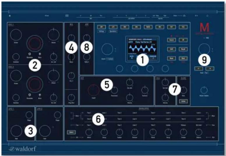
1) Display Section with encoders
2) Wavetable Oscillator Section
3) LFO Section
4) Mixer Section
5) Analog Filter Section (VCF)
6) Envelopes Section
7) VCA, Glide & Master Volume
8) Arpeggiator Section
9) Single/Multi Section

Rear Panel Connections

1) Power Supply Jack & Power Switch
2) Headphones Output with Volume control
3) Stereo Audio Outputs L (Mono) + R
4) Stereo Aux Outputs A - D
5) MIDI Thru, MIDI Out, MIDI In jacks
6) USB 2.0 MIDI Port
7) SD Card Port
8) Kensington ® Compatible Receptacle
About this Manual
This manual was written to help you to become familiar with the M synthesizer. It will also aid experienced users with routine tasks.
To avoid confusion, the terminology in this manual is based on the M parameter names. You will find a glossary at the end of this manual; it explains the various terms used.
We also used a uniform set of symbols to show you topics of particular interest or significance. Important terms are highlighted in bold letters.
Symbols

Caution - The comments that follow this symbol will help you avoid errors and malfunctions.

Info - Additional information on a given topic.

Instruction - Follow these guidelines to execute a desired function.

Example - Real-world examples to try out.
Highlighted Control Features and Parameters
All of the M's buttons, controls and parameters are highlighted in bold letters throughout the manual.
Examples:
- Press the OK button.
• Turn the Cutoff knob.
The M's different modes and parameter pages are illustrated in a depiction of the display.
The value range of a continuous parameter is indicated from low to high with both values shown in italic letters, separated by three dots.
Example:
Cutoff 0...127

General Safety Guidelines

Please read the following safety tips carefully! They include several precautions you should always observe when dealing with electronic equipment. Read all of the instructions before operating your device.
Suitable Operating Conditions
• Use the device in enclosed rooms only.
- Never use the device in damp conditions such as bathrooms, washrooms, or around indoor swimming pools.
- Do not use the device in extremely dusty or dirty environments.
• Make sure that adequate ventilation is available on all sides of the device.
- Do not place the device near heat sources such as radiators.
• Do not expose the device to direct sunlight.
• Do not expose the device to extreme vibrations.
Power Supply
• Only use the power supply adapter that came with M.
- Unplug the device when you are not using it for longer periods.
• Never touch the plug with wet hands.
- Always pull the plug when unplugging the device - never the cable.
Operation
- Never place objects containing liquids on or near the device.
- Place the device on a stable base only. Use a suitable platform.
- Make sure no foreign objects find their way into the chassis. If for some reason this occurs, switch the power off, unplug the device, and consult a qualified repair center.
- This device can generate volume levels that may do irreparable damage to your hearing when used on its own or with amplifiers, speakers, or headphones. For this reason you should keep the volume at tolerable levels.

Maintenance
- Do not open the device or remove the cover. Refer all service and repair tasks to qualified personnel. The interior of the chassis contains no components that require user maintenance.
- Use only a dry, soft cloth or brush to clean the device. Never use alcohol, cleaning solutions or similar chemicals. They will damage the surface of the chassis.
Proper Use
This device is designed exclusively to produce low-frequency audio signals for the purpose of generating sound. Any other use is prohibited and voids the warranty extended by Waldorf Music. Waldorf Music is not liable for damages due to incorrect use.

This M unit is NOT suitable for preparing convenience food. Please cook seasonal and regional whenever it is possible.

Setup and Connections
The Waldorf M comes complete with:
• The Waldorf M Synthesizer
• An external power supply
• This printed Quick Start manual
Please ensure all the above items were included. If something is missing, contact your local dealer.
We recommend that you save the original packing material for future transport.
Setup
Place M on a clean, even surface.
Connections
In order to get started with your M you will need an AC power outlet, a mixing console, an amp, and/or an audio monitor such as a speaker cabinet or a headphone.
You can also use a computer or sequencer to make use of M's MIDI features.
To connect the devices:
- Turn all devices off.
- Connect M's Main Out audio outputs to your mixing console or your computer audio interface. If you want to connect an output monophonically, only use the L/Mono jack of the output pair with a 1/4 inch mono plug. Optionally connect the stereo Headphones outputs to a suited headphone.
- If you want to use a computer, connect M's USB 2.0 port with a USB cable to your computer (Windows or macOS). Thereafter, M becomes automatically available as a MIDI device.
- To play M you need a MIDI master keyboard. Connect its MIDI Out jack to the M's MIDI Input.
- Connect the power supply cable or the power cable that came with your M with the power supply jack. Plug the other side of the power supply cable into a suitable AC power outlet.
- Press the power switch on the rear panel of your M.
- Then switch on your computer (if connected), the mixing console and finally the amplifier or active monitor speakers.
The startup procedure is about 4 seconds. After this, M is ready to play.
The overall volume of M can be controlled with the Master Volume. This also affects the Headphones output. To adjust the level of your headphones, use the headphones gain control as well.
If you do not choose to connect a mixing console, you can patch M's output signals directly to an amplifier or an audio interface. Use an input usually called Line, Aux or Tape input.
M's audio outputs deliver unbalanced line levels. When connecting to an amplifier, a mixing console or an audio interface with automatic balanced/unbalanced sensing inputs, please make sure to use TS mono jack cables and not TRS stereo jack cables.
Before connecting and disconnecting M to a power supply source, turn your amp's volume control all the way down to avoid damage due to on/off switching noise. M produces a high level output signal. Please take care that the connected playback device is suitable for the high level of an electronic instrument. Never use the microphone or phono input of the connected amp!
The Rear Panel Connections
M provides an analog stereo audio output, 4 additional stereo aux outputs and a headphones output. The main audio and headphones outputs are affected by the setting of the Master Volume control dial.
Headphones Output and Headphone Volume
Here you can connect any headphone with a 1/4-inch stereo plug. The headphone output uses the same signal as the main output. The Headphones Volume controls the M's headphone volume in addition to the
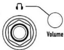
Main Volume knob. Use this knob to amplify or attenuate headphones level to adjust for individual headphone loudness and impedance.
Main Audio Output
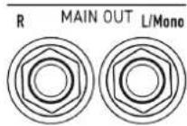
Use 2 TS mono jack cables to connect the Main audio output to a mixer. Use your mixing console to appropriately distribute the stereo channels in case. If you want to connect an output monophonically, only use the
L/Mono jack of the output pair with a 1/4 inch mono plug.
Stereo Aux Outputs A - D
M offers 4 stereo audio aux outputs that can be used to route each of the 4 multi parts to diffe-
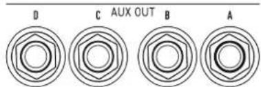
rent outputs, if desired. Connect M's Aux audio outputs to your mixing console ace by using a cable with a stereo TRS jack.
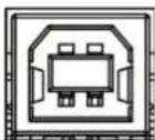
The USB 2.0 Connection
The USB 2.0 port connects M to your computer or iOS device with the following system requirements:
• Windows PC: Windows 7 or newer, a USB 2 port
• Apple: Intel or Apple Silicon Mac with macOS 10.9 or newer, a USB 2 port
- Apple iPad with iOS 9 or newer by using an optional Apple 'Lightning to USB Camera Adapter' cable
The USB connection of M allows transmitting and receiving of MIDI data transmitting.
USB 2.0
SD Card Slot
It is important to use a FAT or FAT32 file system formatted SD card. Other file formats won't work.
! Please insert the SD Card upside, i.e. with the contacts not visible to you. Please insert the card with normal force to avoid any damage.

SD Card
A connected SD card allows:
- Updating M's firmware.
- Importing and saving sound patches.
- Importing and saving M-specific data – e.g. User wave-tables
Although we can hardly believe it, M might not be enough for some people, so we added an elegant way to control external sound modu
MIDI

Thru

Out

In
with M: just connect the DIN MIDI out to your external gear and use the knobs to control certain functions. For use with a computer we recommend the USB 2.0 port.

Setup and Connections
Physical Security
Users that operating with M in areas with public or shared access such as live gigs, public studios or educational establishments can attach a Kensington® compatible security lock to the slot on the rear panel of M.


waldorf
14 M Manual
Basic Operation
Switching On / Off
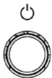
M is equipped with a power switch.

To switch M on:
- Press the Power switch to switch on M. The boot procedure may take a few seconds. After this, the display is lit and M is ready to play.

To switch M off:
- Press the Power switch to switch off M.
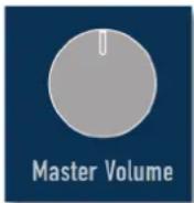
Master Volume
Use the Master Volume to control M's overall volume. The volume setting is global and affects the level of the Main audio outputs including the Headphones output.
The M Mode Pages
M offers mode pages in addition to the panel parameters. To enter a desired mode page, just press the corresponding mode button above the display. The following mode pages are available:

- ARP mode pages
• LFO (2x Low Frequency Oscillators) mode pages
• ENV (VCF, VCA, Wave and Free envelopes) mode pages
• OSC (Oscillators 1 and 2) mode pages
• WAVE (Wavetable 1 and 2 generator) mode pages
• MIX (Mixer) mode pages
• VCF (Voltage Controlled Analog Filter) mode pages
• VCA (Voltage Controlled Amplifier) mode pages

For some modes, press a mode button several times to switch between the corresponding menu pages (e.g. for OSC between Osc 1 and Osc 2).

All modes will be described in detail in the corresponding chapters later in that manual.
! ARP and LFO buttons are also used to switch between System Settings and System Operations when in System mode. Read more on page 65.
The Option Button Section
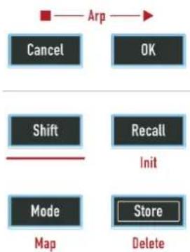
This section offers six buttons regarding the arpeggiator and basic operation functionality. Some buttons offers a second option that can be reached by holding down Shift and pressing the corresponding button with the red labeled text. Here, you find options for sound initializing or storing a sound program.
flowchart
graph TD
    A["Arp"] --> B["Cancel"]
    A --> C["OK"]
    D["Shift"] --> E["Mode"]
    F["Recall"] --> G["Store"]
    H["Init"] --> I["Map"]
    J["Delete"] --> K["Store"]
With the Mode button, you switch between two oscillator models: Classic Microwave 1 and modern Microwave II/XT. Read more on page 32.
The Display and the 4 Encoders
The display gives you an overview of the actual Mode page, parameter changes and delivers additional information. The 4 endless dials below the display control the corresponding parameter that is shown in the lower part of the display next to the dials. The display representation depends on the selected mode, for example in Envelope mode, a graphical envelope is displayed for a clearer editing.
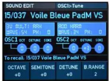
M Display (Oscillator 1 Tune menu page)
The top display area always shows the current mode/mode page, e.g. OSC1>Tune which means, that the Tuning page for Oscillator 1 is selected. Below the mode description, the current loaded Sound or Multi program is displayed. Left to the sound name, the program number is shown.
Loading Sound Programs
M offers a total of 2048 sound programs, divided into 16 banks with 128 sounds each.

To avoid accidental overwriting of the sound edit buffer, you need to press Recall before finally loading a new sound program.

To load a sound program:
- When in Single mode, use the the Single/Multi encoder to select the desired sound program. The bank number, sound slot number and name of the chosen sound is displayed in the lower area of the display.
- Hold down the Shift button and turn the Single/Multi encoder to skip 16 sound slots in one go. This allows a faster navigation within one sound bank.
- Use the Bank/Part buttons to navigate through the 16 sound banks.
- If you want to finally load your desired sound program, press the Recall button. This will overwrite the internal edit buffer and you will lose all edits.
Editing Parameters
In order to change or edit a sound program, you must access the appropriate parameters. Depending on the type of parameters, there are different ways to achieve this:
- The controls on M's front panel offer direct access to the most important sound parameters. The panel is divided into several sections, each containing knobs and dials associated with that section. By adjusting the controls on the panel you have instant access to the sound. These parameters are called Panel Parameters. When editing a Panel parameter, this is displayed in the lower part of the touchscreen display (parameter name and corresponding value with a bar graph).
- Most sections offer additional sound parameters that are available through the display. To edit an additional parameter, press the corresponding mode button above display (e.g. LFO). Use the Sound/System encoder to scroll through the available parameter display pages. These parameters are called Display Menu Parameters. The lower area of the display always shows one to four parameters that can directly edited with the corresponding silver display encoder.

All parameters can be found on the panel and also as display parameters to allow a precise value input.

Basic Operation
- Some rotary controls consist of endless dials or potentiometers. Turning a dial clockwise increases the corresponding value; turning it counterclockwise decreases it. Bipolar parameters (parameters with positive and negative values) use special gradation when changing their values. As soon as the value 0 is reached, the sweep is stopped for a short period to make it easier to edit.
- You can press on some dials to set its parameter value to a default setting.
- Both Wavetable/Wave dials offer a special edit function. The silver outer ring selects the wavetable while the inner dark dial selects the wave position of the current selected wavetable.
If you are lost, press the Recall button to restore all parameters of the original sound program.
Want to start with a clean initialized sound? By clicking Shift + Init, you can initialize the current loaded sound. Keep in mind, that the current sound program is lost
Storing Sound Programs
After you have finished editing a sound program you must save it if you intend to use it again. All of M's memory locations are available for this purpose.
M offers only one active edit buffer for Single or Multi Arrangement patches. This means that your current edit buffer will be immediately replaced when you load a sound from the internal flash storage by selecting patch or bank. Please, take care of saving your edits/newly created patches.
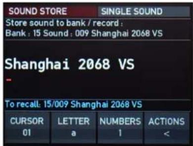
The Sound Store display page
To save a sound program:
- Press the Store button to activate the Sound Store display page (see display graphic above).
- Edit the Name (if desired). Use the first display encoder (CURSOR) to position the cursor. A sound name can have up to 23 characters. With the second encoder (LETTER) you can determine the desired letter. Press on the encoder to switch between capital and lower letters. The third encoder (NUMBERS) lets you enter numbers or special character. Press on the encoder to switch between both. With the fourth encoder (ACTIONS), you can set action characters.
- Use the Single/Multi encoder to select a desired storing location. This is displayed below the sound name. With the Bank/Part buttons, you can determine a desired bank.
- Finally, press the OK button to store the sound program at the selected location. After that, press the Cancel button to leave the Sound Store display page.
- Press the Cancel button to discard the storing process at any time and return to the last selected display page.
Whenever you save a program, the selected memory location is overwritten. Therefore, any previously stored program at this location will be erased. So, you should do backups of your sounds regularly by using the corresponding option in the System Operations. All factory soundbanks can be downloaded from our website, if necessary.
Use the Store function for copying sound programs. There is no need to edit a program before storing it.
You can load/store a complete soundbank (128 patches) from/to SD Card. Please read more on page 71.
Sound Parameters
Waldorf M consists of numerous sound-shaping components.
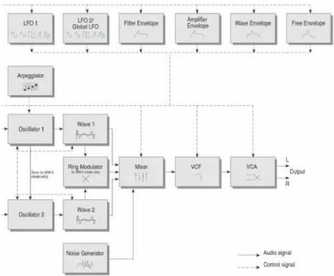
- Sound synthesis: Oscillators with wavetable generators (two modes available: Classic Microwave 1 and Modern Microwave II/XT), VCF Analog Filters and VCA Amplifier. These modules represent the audio signal flow. Sound generation actually occurs within the oscillators. They can produce different wavetables. The VCF analog filter shapes the sound by amplifying (boosting) or attenuating (dampening) certain frequencies. The VCA amplifier are located at the end of the signal chain. It determine the overall volume of the signal.
- Modulators: LFOs, Envelopes. These modules are called Modulators. The Modulators are designed to manipulate or modulate the sound generating components to add dynamics to sounds. The Low-frequency Oscillators (LFOs) are designed for periodic or recurring modulations while Envelopes are normally used for modulations that only occur once on each note. These generators are assigned to parameters on the corresponding display pages and influence these parameters to alter a sound.
flowchart
graph TD
    A["LFO 1"] --> B["Arpeggiator"]
    C["LFO 2/ Global LFO"] --> D["Oscillator 1"]
    E["Filter Envelope"] --> F["Wave 1"]
    G["Amplifier Envelope"] --> H["Mixer"]
    I["Wave Envelope"] --> J["VCA"]
    K["Free Envelope"] --> L["Output R"]
    M["Oscillator 2"] --> N["Wave 2"]
    O["Noise Generator"] --> P["Ring Modulator (in MHz modularity)"]
    Q["Audio signal"] --> R
    S["Control signal"] --> T
    D --> U["Wave 1"]
    F --> V["Wave 2"]
    H --> W["VCF"]
    J --> X["VCA"]
    style A fill:#f9f,stroke:#333
    style C fill:#f9f,stroke:#333
    style E fill:#f9f,stroke:#333
    style G fill:#f9f,stroke:#333
    style I fill:#f9f,stroke:#333
    style K fill:#f9f,stroke:#333
    style M fill:#f9f,stroke:#333
    style Q fill:#f9f,stroke:#333
    style N fill:#f9f,stroke:#333
    style O fill:#f9f,stroke:#333
    style P fill:#f9f,stroke:#333
Signal routing

Global Voice Allocation
Here you can set up Play mode and voice stealing options.
➢ Press Shift + Mode/Map buttons to enter the Voice Allocator display page. Press any of the 8 Mode buttons above the display to switch back to the regular display pages.
PLAYMODE
This option offers 3 settings regarding the play mode:
- Poly: Means that each note triggers its own voice or voices, as on a piano.
- MRetrig (Mono retrigger): Means that only the last played note sounds. All other notes are stored in an internal list but aren't played. As soon as you release the note that is currently played, the second last note is played and so on. Every new note retriggers the envelopes
- MLegato (Mono Legato): Same a MRetrigg, but when you play legato, only the first note that was played triggers the envelopes. All later notes use these envelopes, but sound in the pitch you've played.
V.STEAL (Voice Stealing)
Determines the behaviour of the sound engine, when the maximum available voices are reached:
- M.Late (Mono Latest): When maximum number of voices is reached, the latest note will be cut, when a new note is triggered.
- M.Early (Mono Earliest): When maximum number of voices is reached, the newest note will be cut, when a new note is triggered.
- Lowest: When maximum number of voices is reached, the lowest note will be cut, when a new note is triggered.
- Highest: When maximum number of voices is reached, the highest note will be cut, when a new note is triggered.
These settings are valid for a patch set and stored together with the patch.
In Multi mode, these settings will be overridden by the Multi mode voice allocator (always poly with predefined polyphony).
Wavetable Oscillator Section
M offers two wavetable oscillators with independent wavetable generators.
A wavetable is a table consisting of single waveforms. Each waveform is classified by its own special sound character. The main difference of wavetable synthesis in comparison with other sound-generation principles is the ability to not only to play one waveform per oscillator but also to step through the wavetable via different modulations, thereby creating wavetable sweeps. The results can be dramatic - much more so than anything any sample playback-based system could ever produce.
This principle offers powerful capabilities. To give some examples:
- The Wave Envelope can modulate the position within the wavetable.
• Each note on a keyboard can access a different wave of a wavetable. - An LFO can modulate the position within the wave-table. You can create subtle to drastic sound changes.
- User-selected controllers, such as the Mod wheel, can change the position within the wavetable. When you turn the wheel while playing a chord, each note's wave will be modified instantly.
For more information about Wavetable synthesis please refer to the Appendix of this manual.
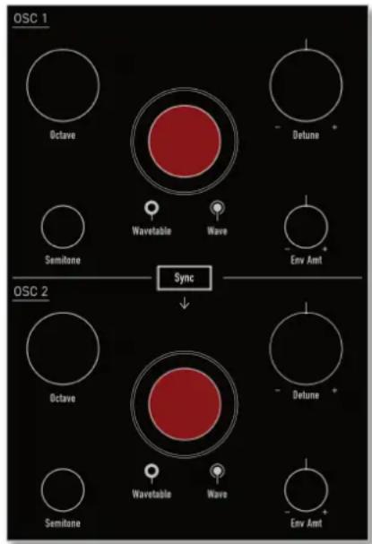
The Oscillator Panel Parameters
Both oscillators offer the same panel parameters.
Keep in mind, that M offers 2 oscillator modes: Classic Microwave 1 and Modern Microwave II/XT. Press the Mode button to switch between these two oscillator models. For more information regarding the Microwave modes please refer to page 32.
Wavetable (Outer black ring dial)
Selects the 96 factory wavetables and your own custom wavetables (UWT 1-31) for the corresponding oscillator.
Wave (Inner red dial)
Determines the start point of the wavetable that is used when the sound starts. As an alternative to the waves of the currently selected wavetable, you can select the basic waveforms triangle, square with 50% duty cycle or sawtooth, when choosing the Wave values 61, 62, or 63.
When you want to create a sound with a wave sweep, you should roughly set the Wave parameter onto the desired wave, before you apply any modulations to the corresponding oscillator. This helps you to find the basic waveform where all modulations start from.
The Wavetables are the real power of your M. To make sure that you have access to all this power, you should make yourself familiar with the sound and the characteristic of each wavetable. The best way to do so is to set up a kind of test sound to listen to the wavetables: Start with an initialized sound (Shift + Recall/Init) and turn down the Mix level for Oscillator 2. In the display, set MOD1AMT to 0. Use the Wave dial to move through the current selected wavetable. Use the Wavetable dial to select another wavetable. You will notice that they cover an extremely wide range of interesting spectral timbres, including analog, FM-like, bell-type or vocal. Note that you can apply unipolar and bipolar modulation sources to the Wave parameter as with any other module. For example, set the Wave parameter to 29, which is almost the middle of the wavetable and apply a slow running LFO to the Wave module to sweep through the whole wavetable (except the three waveforms triangle, square or sawtooth). Try it with one of the PWM wavetables.
Semitone
Determines the pitch of the corresponding oscillator in semitone steps. The standard setting for this parameter is 0, but there are cases where different values are required: Most organ sounds include a quint, therefore one oscillator's semitone parameter must be set to +7. There are also many lead sounds with an interval, e.g. a quart (+5 semitones). When making ring modulated sounds, try to use +11 for the setting.
Octave
Determines the octave setting of the corresponding oscillator. The reference pitch for the oscillator is generated at MIDI note A3 (note no. 69) when Octave, Semitone and Detune is set to 0. In this case the oscillator's frequency will be the same as set in the global Master Tune parameter (normally 440Hz). Set this parameter to 0 if you are creating a typical keyboard sound, set it to -1 for bass sounds. If you are programming strings or other high pitched sound, set Octave to +1.
Detune
Fine-tunes the oscillator in increments of 64ths of a semi-tone. The audible result of detuning oscillators is a flanging. Use a positive setting for one oscillator and an equivalent negative setting for the other. A low value of ±1 results in a slow and soft flange effect. Mid- ranged settings of ±5 are optimal for pads and other fat sounding programs. High values of ±12 or above will give a strong detune that can be used for accordeons or effect sounds.
Env Amt (Envelope Amount)
Determines the amount of influence the wave envelope has on the wavetable modulation for the corresponding oscillator.
Sync Button (only available for Modern Mode)
Enables or disables oscillator synchronisation. When enabled, Oscillator 2 acts as a slave that is controlled by oscillator 1, the master. Each time Oscillator 1 starts a new period, it sends a trigger signal to Oscillator 2, forcing it to restart the wave signal, too. As a result, interesting sound effects may be generated, especially when both oscillators are operating at different pitch settings. Using additional pitch modulation by envelopes, LFOs or pitchbend will bring further movement into sync sounds.
The Oscillator Display Parameters
➢ Press the OSC button above the display to show the oscillator display pages for the corresponding oscillator 1 or 2. The current selected oscillator page is shown in the upper right corner of the display, e.g.
OSC2. Use the Sound/System encoder to scroll through the display pages.
Both oscillators pages offer nearly the same display parameters.
Osc 1 & 2 Tune Pages
Here you find all parameters regarding oscillator tuning.
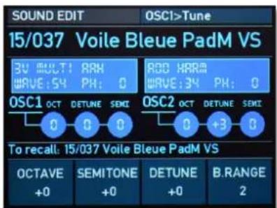
Oscillator 1 Tune display page
The display also informs you about the current selected wavetables, their Wave positions, and the oscillator's tuning status.
OCTAVE
Same functionality as for the corresponding panel parameter.
SEMITONE
Same functionality as for the corresponding panel parameter.
DETUNE
Same functionality as for the corresponding panel parameter.
B.RANGE (Bend Range)
Determines the intensity of the pitchbend (from 0 to 12 semitones) via MIDI Pitchbend messages in semitones for the corresponding oscillator.
Sound Parameters
Osc Mod 1 and 2 Pages
Here you find all parameters regarding the oscillator pitch modulations.
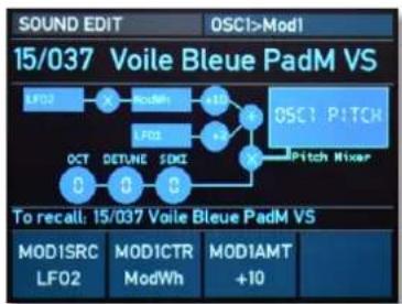
Oscillator 1 Mod 1 display page
The display also informs you about the current made modulations and the oscillator's tuning status.
MOD1SRC (Modulator 1 Source)
Selects the modulation source for the pitch modulation of the corresponding oscillator.
MOD1CTR (Modulator 1 Sidechain Controller)
Selects the sidechain controller that is used to scale the output of the modulation source. A typical example is the Modulation wheel as source and a LFO as the controller. This allows you to control the intensity of the LFO modulation using the wheel. If no controller is selected, no modulation takes place. If you want to use a classic source * destination behavior, set MOD1CTR to Max.
MOD1AMT (Modulator 1 Amount)
Determines the amount of modulation applied to the corresponding oscillator pitch. This parameter can be set to both positive and negative values.
MOD2SRC (Modulator 2 Source)
Selects a second modulation source for the pitch modulation of the corresponding oscillator.
MOD2AMT (Modulator 2 Amount)
Determines the amount of modulation applied to the corresponding oscillator pitch. This parameter can be set to both positive and negative values.
Sound Parameters
MOD2QNT (Modulator 2 Quantize Depth)
Gradually transforms continuous modulations like a LFO sine-wave into discreet steps. If set to 0, no quantization is introduced to the modulation signal. Values from 1...7 introduces different levels of quantization, thus changing the modulation's output from a continuous waveform to a quantized wave of discreet steps.

Use higher quantization values together with a LFO as source to achieve sample-and-hold effects.
LINKMOD (only available for Oscillator 2)
Link allows the same pitch modulation settings for both oscillators to be used. When enabled, oscillator 2 uses the pitch modulation parameters of oscillator 1 for all modulation settings and pitchbend messages. That means, whenever a modulation is applied to oscillator 1, it is also applied to oscillator 2. When disabled, each oscillator uses its own individual modulation settings.
Osc Sync & Glide Page
Here you find parameters regarding the oscillator synchronisation and glide functions.
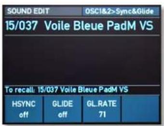
Oscillator 1 & 2 Sync&Glide display page
HSYNC (Hard Sync, only in Modern mode)
Enables or disables oscillator synchronisation. When enabled, oscillator 2 acts as a slave that is controlled by oscillator 1, the master. Each time oscillator 1 starts a new period, it sends a trigger signal to oscillator 2, forcing it to restart the wave signal, too. As a result, interesting sound effects may be generated, especially when both oscillators are operating at different pitch settings. Using additional pitch modulation by envelopes, LFOs or pitchbend will bring further movement into sync sounds.
GLIDE
Same functionality as for the Glide panel button.

Sound Parameters
GL RATE
Same functionality as for the Glide Rate panel parameter.
Osc Tweaks Page
Here you find parameters with additional settings for both oscillators.
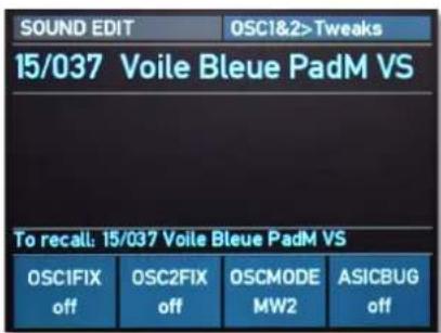
Oscillator 1 & 2 Tweaks display page
FIXPITCH 1 / FIXPITCH 2
Determines, if incoming MIDI notes will change M's pitch or not. If set to off, incoming notes change the oscillator's pitch as defined by the corresponding MIDI note, as you would usually expect. If set to on, a note on message will still trigger the oscillator, but the incoming pitch will be ignored. The result is the same pitch for every key, the default is MIDI note number 60 (C3).
OSCMODE
Same functionality as for the Mode button on the panel. This settings is stored in a Sound program. Read more on page 32.
ASICBUG (only in Classic mode)
The ASIC mixing bug is a special setting of the Waldorf M, which allows it to reproduce this former issue and use this for special sound design intentionally. Originally, this is a numeric overflow bug in the Microwave I ES2 ASIC chip, which produces a strong distortion of the sound if the sum of the oscillator's level setting was greater than 8. This effect was used by some sound designers to produce a gritty harsh sounds. This option is switched off by default. By activate it, the resulting effect could be checked by using two oscillators with sine waves and mix level settings that sum should be greater than 128.

The Wave Display Parameters
➢ Press the WAVE button above the display to show the Wave display pages for the corresponding oscillator 1 or 2. The current selected Wave oscillator page is shown in the upper right corner of the display, e.g. WAV1. Use the Sound/System encoder to scroll through the display pages.
Both Wave pages offer nearly the same display parameters.
Wave Page
Here you find all parameters regarding the wavetables.
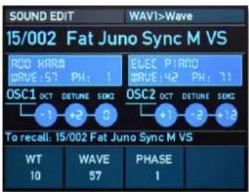
Wave 1 Wave display page
The display also informs you about the current selected wavetables, their Wave positions, and the oscillator's tuning status.
WT (Wavetable)
Same functionality as for the corresponding panel parameter.
WAVE
Same functionality as for the corresponding panel parameter.
PHASE
By means of this parameter you can define the Startwave and, as a result, the phase of the generated wave. Alternative to a fixed value, you can use free to set the phase to a different, random value each time a note is generated.
Sound Parameters
Wave Envelope Page
Here you find all parameters regarding the wavetable envelope.
flowchart
graph TD
    A["LV01"] --> B["X"]
    B --> C["LV03"]
    C --> D["+3"]
    D --> E["Wave Position"]
    F["Keytrack"] --> G["-11"]
    G --> H["Mc3h"]
    H --> I["+24"]
    I --> J["Wave Position"]
    K["Velocity"] --> L["+0"]
    L --> M["Wave Enr"]
    M --> N["+37"]
    N --> O["Wave Position"]
    P["#RVE1:57 Wave Position"]
    Q["To recall: 15/002 Fat Juno Sync M VS"]
    R["ENVAMT +17"] --> S["ENVVELO +0"]
    T["KTRACK +12"] --> U["KTRACK +12"]
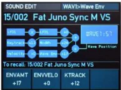
Wave 1 Wave Envelope display page
The display also informs you about the current made modulations and the oscillator's tuning status.
ENVAMT (Envelope Amount)
Same functionality as for the corresponding panel parameter.
ENVVELO (Envelope Velocity)
Determines the amount of influence the wave envelope has on the wavetable modulation, based on key velocity. In conjunction with EnvAmt you can create nice effects when you set one of the two parameters to a negative setting while the other one is set to a positive setting.
KTRACK (Keytracking)
Determines the amount of wavetable modulation depending on the received MIDI note number. Reference note for this parameter is C3, note number 60. For positive settings the modulation amount is increased for notes above to reference note, for negative settings the amount is decreased. A setting of +63 corresponds to a 1:1 scale. This means that each note above or below the reference note plays a different wave.
Wave Modulation Pages
Here you find all parameters regarding the wavetable modulations.
flowchart
graph LR
    A["LFOs"] --> B["X"]
    B --> C["LFOs"]
    C --> D["+0"]
    D --> E["#RVE1:57 Wave Position"]
    F["Compact"] --> G["-1.3"]
    G --> H["+0"]
    H --> I["NuMn"]
    I --> J["+24"]
    J --> K["+17"]
    K --> L["+17"]
    L --> M["+17"]
    M --> N["+17"]
    N --> O["+17"]
    O --> P["+17"]
    P --> Q["+17"]
    Q --> R["+17"]
    R --> S["+17"]
    S --> T["+17"]
    T --> U["+17"]
    U --> V["+17"]
    V --> W["+17"]
    W --> X["+17"]
    X --> Y["+17"]
    Y --> Z["+17"]
    Z --> AA["+17"]
    AA --> AB["+17"]
    AB --> AC["+17"]
    AC --> AD["+17"]
    AD --> AE["+17"]
    AE --> AF["+17"]
    AF --> AG["+17"]
    AG --> AH["+17"]
    AH --> AI["+17"]
    AI --> AJ["+17"]
    AJ --> AK["+17"]
    AK --> AL["+17"]
    AL --> AM["+17"]
    AM --> AN["+17"]
    AN --> AO["+17"]
    AO --> AP["+17"]
    AP --> AQ["+17"]
    AQ --> AR["+17"]
    AR --> AS["+17"]
    AS --> AT["+17"]
    AT --> AU["+17"]
    AU --> AV["+17"]
    AV --> AW["+17"]
    AW --> AX["+17"]
    AX --> AY["+17"]
    AY --> AZ["+17"]
    AZ --> BA["+17"]
    BA --> BB["+17"]
    BB --> BC["+17"]
    BC --> BD["+17"]
    BD --> BE["+17"]
    BE --> BF["+17"]
    BF --> BG["+17"]
    BG --> BH["+17"]
    BH --> BI["+17"]
    BI --> BJ["+17"]
    BJ --> BK["+17"]
    BK --> BL["+17"]
    BL --> BM["+17"]
    BM --> BN["+17"]
    BN --> BO["+17"]
    BO --> BP["+17"]
    BP --> BQ["+17"]
    BQ --> BR["+17"]
    BR --> BS["+17"]
    BS --> BT["+17"]
    BT --> BU["+17"]
    BU --> BV["+17"]
    BV --> BW["+17"]
    BW --> BX["+17"]
    BX --> BY["+17"]
    BY --> BZ["+17"]
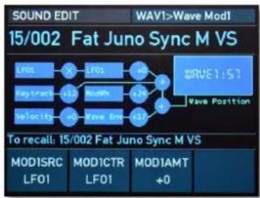
Wave 1 Wave Envelope display page
The display also informs you about the current made modulations and the oscillator's tuning status.
MOD1SCR
Selects the modulation source for the wavetable modulation of the corresponding oscillator.
MOD1CTR
Selects the sidechain controller that is used to scale the output of the modulation source. A typical example is the Modulation wheel as source and a LFO as the controller. This allows you to control the intensity of the LFO modulation using the wheel. If no controller is selected, no modu-
lation takes place. If you want to use a classic source * destination behavior, set MOD1CTR to Max.
MOD1AMT
Determines the amount of modulation applied to the corresponding wavetable modulation. This parameter can be set to both positive and negative values.
MOD2SCR
Selects a second modulation source for the wavetable modulation of the corresponding oscillator.
MOD2AMT
Determines the amount of modulation applied to the corresponding wavetable modulation. This parameter can be set to both positive and negative values.
LINKMOD (only available for Wave 2)
Allows the use of the same wave modulation settings for both waves. When enabled, wave 2 uses the modulation parameters of wave 1 for all Modulation settings, EnvAmt, EnvVelo and Ktrack. That means, whenever a modulation is applied to wave 1, it is also used for wave 2. When disabled, each wave uses its own individual modulation settings.
Classic Mode vs. Modern Mode
As you have probably already noticed, M offers two different operating modes for the oscillators - the Classic Microwave I mode and the Modern Microwave II/XT mode.
To switch between both modes, press the Mode button right to the display. If the buttons lits, the Modern Microwave II/XT mode is active.
The wavetables oscillators behave differently in both modes. Major differences are :
- There is no Hard Sync and Ring Modulation available in Classic Microwave I mode.
- 16-bit wavetables are bit-reduced to 8 bit in the Classic Microwave I mode.
- The Classic mode offers a 240 kHz no-antialiased sample rate. The Modern mode offers a 40 kHz sample rate with bandlimited wavetables.
- There is no "ASIC Mix Bug" setting available for the Modern Microwave II/XT mode.
There is one restriction regarding the use of the Modern Oscillator mode in Multi mode: Only the first Part can use the Modern mode.
Oscillator Mixer (MIX) Section
In the Oscillator Mixer section you control the volumes of both oscillators and the Noise generator. If an oscillator volume dial is turned fully counterclockwise, no signal is passed.
It is possible to introduce analog saturation of the VCF input. The VCF circuit in the Waldorf M was designed to saturate about 70% of the oscillator's maximum mixer output (oscillator level setting 75 and above). This analog saturation acts as a mild overdrive effect and brings a little more warmth to the sound. The effect may vary depending on the waveform of the oscillators or their combination. In order to check this effect sonically, it is recommended to select the single oscillator of the sine wave and increase the level of this oscillator until the saturation can be heard.


The Mix Section Panel Parameters
Osc 1
Volume of Wave oscillator 1.
Osc 2
Volume of Wave oscillator 2.
In the earlier Microwave there was a bug in the sound generation chip that caused the levels to be distorted under certain circumstances. We have recreated this bug, and it can be activated/deactivated for each sound program. Read more about this on page 28.
Noise
Volume of the noise generator. The noise generator produces pink noise and features no other controls. Noise is a fundamental source for any kind of analog-type percussion. Also wind and other sound effects can be created by using the noise generator.
Ring Mod (only in Modern Microwave Mode)
Press the Mode button to switch between the two oscillator models: Classic Microwave 1 and Modern Microwave II/XT. For more information regarding the Microwave modes please refer to page 31.
Determines the volume of the ring modulation between both Wave oscillators. From a technical point of view ring modulation is the multiplication of the waves' signals. The result of this operation is a waveform that contains the sums and the differences of the source frequency components. Since the ring modulation generates disharmonic components, it can be used to add metallic distorted sound characteristics. This is useful e.g. when generating synth percussion. Please note that in a complex waveform all harmonic component behave like interacting sine waves, resulting in a wide spectral range of the ring modulated sound.
The Mix Display Parameters
② Press the MIX button above the display to show the Mix display pages. The current selected Mix page is shown in the upper right corner of the display, e.g. MIX>Levels. Use the Sound/System encoder to scroll through the display pages.
bar
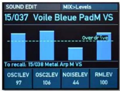
SOUND EDIT MIX>Levels | Measurement | Value | | :--- | :--- | | 15/037 Voile Bleue PadM VS | Over drive | | TO recall: 15/038 Metal Arp M VS | 97 | | OSC1LEV | 106 | | OSC2LEV | 44 | | NOISELEV | 100 |Mix Levels display page
The display for all 3 mix pages also informs you about the current level status for all sound generation sources.
Levels Page
Here you find all parameters regarding the mixer levels.
OSC1LEV (Oscillator 1 Level)
Same functionality as for the corresponding panel parameter.
OSC2LEV (Oscillator 2 Level)
Same functionality as for the corresponding panel parameter.
NOISELEV (Noise Level)
Same functionality as for the corresponding panel parameter.
RMLEV (Ring Modulator Level)
Same functionality as for the corresponding panel parameter.

Sound Parameters
Mix Modulation Pages
Here you find all parameters regarding the wavetable modulations.
01MODS
Selects the modulation source for the oscillator 1 level modulation.
01MODA
Determines the amount of modulation applied to the oscillator 1 level. This parameter can be set to both positive and negative values.
02MODS
Selects the modulation source for the oscillator 2 level modulation.
02MODA
Determines the amount of modulation applied to the oscillator 2 level. This parameter can be set to both positive and negative values.
NSEMODS
Selects the modulation source for the noise generator level modulation.
NSEMODA
Determines the amount of modulation applied to the noise generator level. This parameter can be set to both positive and negative values.
RMMODS
Selects the modulation source for the ring modulator level modulation.
RMMODA
Determines the amount of modulation applied to the ring modulator level. This parameter can be set to both positive and negative values.

VCF Section
M offers an analog lowpass filter with 24dB/Oct and resonance. This is a SSI 2144 Ladder type with saturation. This filter type dampens frequencies which are higher than the specified cutoff frequency. Frequencies below this threshold are hardly affected. To give you an idea of the extent of damping, consider this: A reduction of 24dB reduces the original level by approx. 94%. The damping factor two octaves above the cutoff point reduces the original level by more than 99%, which in most cases means this portion of the signal is no longer audible. M's filter also features a resonance parameter. Resonance in this context means that a narrow frequency band around the cutoff point is emphasised. If the resonance is raised to a great extent, then the filter will begin self-oscillation, i.e. the filter generates an audible sine wave even when it does not receive an incoming signal.
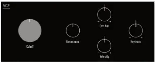
The VCF Section Panel Parameters
Cutoff
Determines the cutoff frequency for the low pass filter. All frequencies above the cutoff frequency are damped. You can bring more movement into the sound by modulating the cutoff frequency via the LFOs, the VCF Envelope or the Keytrack parameter. At a value of 50 and a Resonance value of 80, the filter oscillates with 1046.5 Hz, which is equal to note C6. Tuning is scaled in semitone steps. When Keytrack is set to +63, the filter can be played in a tempered scale with a tolerance of +/- 2 cents within 5 octaves.
Resonance
Determines the amplification of the frequencies around the cutoff point. Use lower values in the range 0...60 to give more brilliance to the sound. At higher values of 60...80 the sound gets the typical filter character with a strong boost around the cutoff frequency and a loss in the other range. When the setting is raised to values above 80, the filter starts to self-oscillate, generating a pure sine wave. This feature can be used to create solo sounds like the traditional "moog lead" or analog-style effects and percussion like electronic toms, kicks, zaps etc.
Env Amt (VCF Envelope Amount)
Determines the amount of influence the VCF envelope has on the cutoff frequency. For positive settings, the filter cutoff frequency is increased by the modulation of the envelope, for negative settings, the cutoff frequency is decreased. Use this parameter to change the timbre of the sound over time. Sounds with a hard attack usually have a positive envelope amount that makes the start phase bright and then closes the filter to get a darker sustain phase. On the other side string sounds usually use a negative envelope amount that gives a slow and dark attack before the cutoff rises in the sustain phase.
Velocity
Determines the amount of influence the VCF envelope has on the cutoff frequency, based on key velocity. This parameter works similarly to the Env Amt parameter with the difference that its strength is velocity based. Use this feature to give a more expressive character to the sound. When you hit the keys smoothly, only few modulation is applied. When you hit them harder, the modulation amount also gets stronger.
Keytrack
Determines how much the cutoff frequency depends on the MIDI note number. The reference note for Keytrack is C3, note number 60. For positive settings, the cutoff frequency rises on notes above the reference note, for negative settings the cutoff frequency falls up to higher notes and vice versa. A setting of +0 corresponds to a 1:1 scale, so e.g. when an octave is played on the keyboard the cutoff frequency changes for the same amount. If you want to play the filter in a tempered scale, e.g. for a solo sound with self-oscillation, set the value to +0%. On most bass sounds lower settings are optimal to keep the sound smooth at higher notes.
The VCF Display Parameters
Press the VCF button above the display to show the VCF display pages. The current selected VCF page is shown in the upper right corner of the display, e.g. VCF>General. Use the Sound/System encoder to scroll through the display pages.
General Page
Here you find all parameters regarding the filter settings.
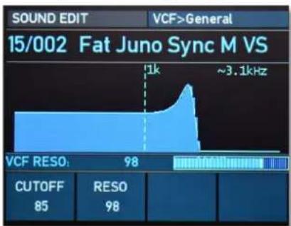
line
| Metric | Value | | ------------ | ----- | | CUTOFF | 85 | | RESO | 98 |VCF General display page
CUTOFF
Same functionality as for the Cutoff panel parameter.
RESO
Same functionality as for the Resonance panel parameter.
ENVAMT
Same functionality as for the corresponding Env Amt panel parameter.
ENVVELO
Same functionality as for the corresponding Velocity panel parameter.
KTRACK
Same functionality as for the Keytrack panel parameter.
Mod1 Page
Here you find all parameters regarding the filter modulations.

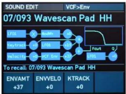
flowchart
graph LR
    A["LF01"] --> B["X"]
    B --> C["ModMn"]
    C --> D["+0"]
    D --> E["+15"]
    E --> F["Fcut"]
    F --> G["Q"]
    G --> H["LFO1"]
    H --> I["+0"]
    I --> J["+37"]
    K["Keytrack"] --> L["+0"]
    L --> M["LF01"]
    M --> N["+0"]
    N --> O["+37"]
    P["Velocity"] --> Q["+0"]
    Q --> R["+37"]
    S["To recall: 07/093 Wavescan Pad HH"]
VCF General display page
The VCF Env / Mod1 / Mod2/Reso Mod display pages also inform you about the current made modulations and the filter setting status.
MOD1SCR
Selects the modulation source for the filter cutoff modulation.
MOD1CTR
Selects the sidechain controller that is used to scale the output of the modulation source. A typical example is the Modulation wheel as source and a LFO as the controller.
This allows you to control the intensity of the LFO modulation using the wheel. If no controller is selected, no modulation takes place. If you want to use a classic source * destination behavior, set MOD1CTR to Max.
MOD1AMT
Determines the amount of modulation applied to the filter cutoff frequency. This parameter can be set to both positive and negative values.
Mod2/Reson Mod Page
Here you find more parameters regarding the filter modulations.
MOD2SCR
Selects a second modulation source for the filter cutoff modulation.
MOD2AMT
Determines the amount of modulation applied to the filter cutoff modulation. This parameter can be set to both positive and negative values.
Sound Parameters
R.MODSRC
Selects a second modulation source for the filter resonance modulation.
R.MODAMT
Determines the amount of modulation applied to the filter resonance modulation. This parameter can be set to both positive and negative values.
VCA Section
M offers an a true stereo analog VCA with panning option.
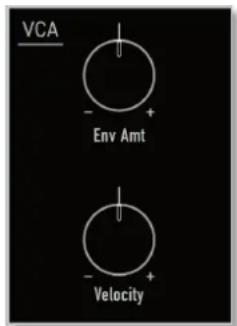
The VCA Section Panel Parameters
Env Amt
Determines the amount of influence the VCA envelope has on the volume. For positive settings, the volume is increased by the modulation of the envelope, for negative settings, the volume is decreased. Sounds with a hard attack usually have a positive envelope amount that makes the start phase louder and then closes the VCA to get a smoother sustain phase.

Sound Parameters
Please note that negative values are also possible, so the VCA envelope is used inverted. A setting of 0 switches the VCA off (as with Microwave 1). The reason for this is that M applies all modulations (EG * EG Amount) as CV source and not to the VCA CV itself (as for example for the VCF). So if there is 0 as EG Amount, no sound is hearable.
Velocity
Specifies how much volume will be affected by keyboard velocity. Use this feature to give more expression to the sound. With a setting of 0, velocity will have no effect on the volume. Classic organs work in this way because they do not have dynamic response. For positive settings, the volume rises up to higher velocities. This is the most commonly used setting which gives a piano-like character. For negative settings, the volume falls up to higher velocities. This gives an untypical character suitable for effect sounds. As the Amplifier always works in conjunction with the VCA Envelope, this parameter actually determines the envelope velocity amount.
You need use the VCA envelope by setting its envelope amount or velocity parameters different to 0; otherwise there will be no output at all. Therefore you must define the volume envelope in a useful way even if you intend to use another envelope to shape the sounds loudness.
The VCA Display Parameters
Press the VCA button above the display to show the VCA display pages. The current selected VCA page is shown in the upper right corner of the display, e.g. VCA>Volume&Pan. Use the Sound/System encoder to scroll through the display pages.
All VCA display pages also inform you about the current made modulations.
Sound Parameters
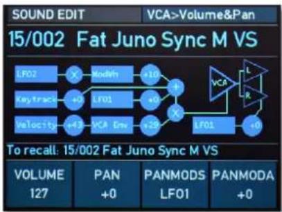
VCA Volume & Pan display page
Volume & Pan Page
Here you find all parameters regarding the volume and panning settings.
VOLUME
Determines the overall volume of the sound program.
PAN
Determines the position in the stereo panorama. When the setting is -64, the sound is panned far left, when the setting is right +63, it is panned far right. If you want to set the sound into the middle of the stereo panorama, use the +0 setting (or press the PAN display dial once). To give further movement to the sound, set this parameter to a basic value and apply some modulation to it e.g. via a LFO.
PANMODS
Selects the modulation source for the panning modulation.
PANMODA
Determines the amount of modulation applied to panning. This parameter can be set to positive and negative values.
Env Page
Here you find all parameters regarding the VCA envelope modulations.
ENVAMT (Envelope Amount)
Same functionality as for the Env Amt panel parameter.
ENVVELO (Envelope Velocity)
Same functionality as for the Velocity panel parameter.
KTRACK
Determines how much the volume depends on the MIDI note number. The reference note for Keytrack is C3, note
Sound Parameters
number 60. For positive settings, the volume increases on notes above the reference note, for negative settings the volume decreases up to higher notes and vice versa. This setting can be useful to adjust a sound's volume over the whole keyboard range. Especially when extensive filtering is used, the sound can be louder on the lower or the upper part of the keyboard. On the other side, you can apply this effect intentionally e.g. for effect sounds.
Mod1 Page
Here you find parameters regarding the amplifier modulations.
MOD1SCR
Selects the modulation source for the amplifier volume modulation.
MOD1CTR
Selects the sidechain controller that is used to scale the output of the modulation source. A typical example is the Modulation wheel as source and a LFO as the controller. This allows you to control the intensity of the LFO modulation using the wheel. If no controller is selected, no modulation takes place. If you want to use a classic source * destination behavior, set MOD1CTR to Max.
MOD1AMT
Determines the amount of modulation applied to the amplifier volume. This parameter can be set to both positive and negative values.
Mod2 Page
Here you find additional parameters regarding the amplifier modulations.
MOD2SCR
Selects a second modulation source for the amplifier volume modulation.
MOD2AMT
Determines the amount of modulation applied to the amplifier volume. This parameter can be set to both positive and negative values.
Glide Section
Glide (or portamento) describes the continuous gliding from one note to the next like strings or some brass instruments (e.g. trombone) can do. A glissando is a similar effect with one difference: The pitch does not change continuously but in note steps. On acoustic instruments a glissando can be performed e.g. on a piano when you play very fast over a wide key range.
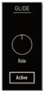
The Glide Panel Parameters
Active Button
Enables or disables the glide effect.
Rate
Determines the glide time. Low values will give a short glide time in the range of milliseconds that gives a special character to the sound. High values will result in a long glide time up to several seconds which can be useful for solo and effect sounds.
The Glide Display Parameters
The Glide display parameters can be found in the Osc 1&2 Sync & Glide display pages. Please refer to page 27.

LFO Section
In addition to the main oscillators, M is equipped with two low frequency oscillators (LFOs) that can be used for modulation purposes. Each LFO generates a periodic waveform with adjustable frequency rate and shape.
Both LFOs offer nearly the same panel and display parameters.
Keep in mind that there is a third "hidden" global LFO that uses the controls of LFO2, when active. More on that on the following pages.
The LFO Section Panel Parameters
Rate
Determines the frequency of the generated signal of the corresponding LFO. The current rate is also displayed in Hertz in the upper right corner of the LFO waveform representation in the display.
Shape
Determines the type of waveshape to be generated by the corresponding LFO (Sine, Triangle, Pulse, Random, S&H = Sample & Hold). S&H is a sampled value of the "opposite"
LFO. E.g., the S&H shape of LFO1 samples LFO2 and vice versa. More variations can be achieved by means of the SYMM parameter. Please read the corresponding paragraph later on in this chapter.
The LFO Display Parameters
Press the LFO button above the display to show the LFO display pages. The current selected LFO page is shown in the upper right corner of the display, e.g. LFO>General. Use the Sound/System encoder to scroll through the display pages.
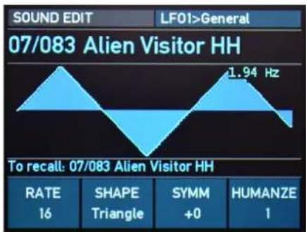
line
SOUND EDIT LF01>General | Measurement | Value | | :--- | :--- | | 07/083 Alien Visitor HH | 1.94 Hz | | To recall: 07/083 Alien Visitor HH | | | RATE | 16 | | SHAPE Triangle | | | SYMM +0 | | | HUMANZE | 1 |LFO1 General display page
All LFO display pages show also a graphical representation of the current LFO shape.
LFO General (for LFO 1 and 2)
Here you find all parameters regarding the LFO 1 and 2 settings.
RATE
Same functionality as for the corresponding Rate panel parameter.
SHAPE
Same functionality as for the corresponding Shape panel parameter.
SYMM
Adjusts the relationship between the rising and the falling edge of the corresponding LFO signal. When set to 0 the generated waveshape is symmetrical. When set to positive values, the positive cycle becomes longer and the negative cycle becomes shorter and vice versa. Use this parameter to change the pulsewidth of the LFO square shape. When using it on a triangle waveshape, you can get a sawtooth wave with a soft rising or falling slope.
HUMANZE
Adds a random variation to the corresponding LFO speed at each cycle. When disabled, the LFO remains at its initial speed, preset by the Rate parameter. Low settings add a human touch to the sound, high settings are useful when creating effect sounds with an irregular character e.g a wind sound where the filter frequency is modulated by an LFO.
Mod Page (only LF01)
Here you find all parameters regarding the LFO modulations.
RTEMODS
Selects the modulation source for the LFO 1 rate modulation.
RTEMODA
Determines the amount of modulation applied to the LFO 1 rate.
LEVMODS
Determines the source to alter the LFO level. Since the actual level of LFO intensity is set at the destination, ther
eis no further amount value needed here. Instead, full pōsitive modulation is always applied whenever a source is selected. If you do not want to use any dynamic modulation at all, select Max as a source.
Sync&Env Page (only LF01)
Here you find parameters regarding the LFO behaviour.
SYNC
Determines if the LFO is synchronised. If off is selected, the LFO runs completely independent for each note and resets on the note onset. Use Humanize to even further enhance this behavior. If on is selected, all LFOs of the M's voices used by the sound program behave as one. Use a modest Humanize value to imitate bad circuit design.
Use the option to emulate analog synths of the 1970s/1980s equipped with only one LFO.
DELAY
Determines the start of the LFO EG (see next parameters).
ATTACK
Determines the attack of the simple useful AD envelope to control the LFO 1 level. A setting of θ gives instantaneous attack after the Delay time has passed. 127 ist the longest Attack time, requiring several minutes to fade in the LFO completely.
DECAY
Adjusts the decay time of the LFO envelope. 0 does not introduce any decay at all. Rather, the LFO will fade in according to the Attack parameter and stay constant throughout the keypress. To guarantee a smooth LFO modulation, upon release of the key the LFO will follow the VCA envelope curve in its release phase. In this configuration, the LFO is turned into an AR (attack/release) envelope. Values of 1...127 adjust the decay time of the LFO envelope, which now acts as an AD (attack/decay) envelope.
Sync Page (only LF02)
Here you find parameters regarding the LFO 2 synchronisation.
PH.SHIFT
If disabled (off), LFO 2 operates independently from LFO 1. If enabled, the rate and phase of the generated LFO2 signal is defined by LFO 1. The Phase Shift parameter defines the angle in degrees (from 2 to 180) from which LFO 2's signal is phase shifted to LFO 1. The use of this function only makes sense when using a regular waveshape like sine, triangle or square.
GLOBAL
When active (on), the global LFO acts as a kind of "shadow copy" of LFO2. This global LFO is following the settings of LFO2 - Rate, Shape, Symmetry, and Humanize. However, it does NOT means that LFO2 is not a voice LFO anymore. LFO2 is staying back in its place (as a voice LFO). This global LFO is actually a third "synth level" LFO, which in addition could be synced to MIDI clock (see next options)
MIDISYNC
If set to on, the global LFO is synchronised to an incoming MIDI Clock signal.
MSYNCTO
If set to on, the Rate value of the global LFO can be set in musical notation. The range goes from 1/32 up to 1024
bars, dependings on the BPM tempo (internal 40-300 BPM). It covers a frequency ranges from 0.000065 Hz (about one cycle in ca. 4 hours 15 minutes) up to 160 Hz (which reaches in fact the audible range).

When working with high LFO rates, this could produce sometimes audible aliasing effects, when applied to the certain destination, related to the analog CVs of VCF or VCA.

Envelopes Section
M's 4 programmable envelopes allow you to manipulate sound parameters via rate or timed modulations.
• VCF DADSR. This envelopes is designed to control the VCF, but can also be used for other modulations.
• VCA ADSR. This envelope is designed to control the sound volume, but can also be used for other modulations.
• Wave. This loopable envelope with 8 different times and levels (multi segment envelope) is designed to control the wave scanning for a wavetable, but can also be used for other modulations.
• Free. This loopable envelope with 4 different times and levels (multi segment envelope) can be used freely to perform modulations on any module.
[Non-Text]
An ADSR envelope is started by pressing a key. It ascends to its maximum value at the rate determined by the Attack parameter. It then descends at the rate determined by the Decay value until it reaches the predetermined Sustain value. It remains at this value until the key is released. The envelope then descends to zero at the rate determined by the Release parameter.
11
Multi segment envelopes are extremely flexible modulation sources. Their structure is made of grouped time/level parameters that allows one to generate an almost free modulation amount over several time segments. The envelope consists of several single segments, that can be divided into a sustain and a release phase. The crossover point between these two phases can be determined by selecting the corresponding segment number. The envelope is started by pressing a key. It ascends to the Level 1 value at the rate determined by the Time 1 parameter. In the next time segment Time 2 the amplitude moves to the Level 2 value. The same procedure is processed for the following segments until the end of the sustain phase is reached. The envelope then moves on to process the remaining segments until it finally ends with its last value Level 8. In fact you can reduce the number of processed segments to get things easier. Additionally you can repeat specific segments by installing loops in the sustain phase as well as in the release phase.

The Envelope Section Panel Parameters
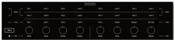
Select Button
Selects the envelopes that can be controlled by the panel parameters. For example, press Select until the VCF/VCA LED lits. In this case, the leftmost 4 dials control the Filter envelope, the rightmost 4 dials control the Amplifier envelope.
Parameters for the VCF/VCA Envelopes
Both VCF and VFA ADSR envelopes offer the same panel and display parameters.
Attack (for VCF & VCA Envelopes)
Determines the attack rate or amount of time it takes for a signal to go from zero to maximum level.
Decay (for VCF & VCA Envelopes)
Determines the decay rate or amount of time it takes for a signal to reach the Sustain level.
Sustain (for VCF & VCA Envelopes)
Determines the sustain level that is held until a note ends.
Release (for VCF & VCA Envelopes)
Once the note has ended, the release phase begins. During this phase, the envelope fades to zero at the rate determined by the release value.
Parameters for the Wave/Free Envelopes
M's Wave envelope offers a multi segment characteristic with 8 separately adjustable times and levels. The Free envelope features 4 times/levels.
To edit the 8 stages of the Wave envelope, use the Select button to switch between Time/Level 1...4 and Time/Level 5...8).
Sound Parameters
Time (for Wave & Free Envelopes)
Determines the time for the individual segment to reach its end level. The Wave envelope offers 8 Time parameters, the Free envelope offers 4 Time parameters.
Level (for Wave & Free Envelopes)
End level that the corresponding segment finally reaches. The Wave envelope offers 8 Level parameters, the Free envelope offers 4 Level parameters.
The Envelope Display Parameters
② Press the ENV button above the display to show the Envelope display pages. The current selected Env page is shown in the upper right corner of the display, e.g. WAVE ENV>General. Use the Sound/System encoder to scroll through the display pages.
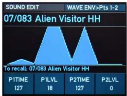
area
SOUND EDIT WAVE ENV>Pts 1-2 | Measurement | Value | | :--- | :--- | | P1TIME | 127 | | P1LVL | 18 | | P2TIME | 127 | | P2LVL | 0 | To recall: 07/083 Alien Visitor HHWAVE Envelope Points 1-2 display page
All envelope display pages show also a graphical representation of the current envelope shape.
Sound Parameters
General Pages (for VCF and VCA envelope)
Here you find all parameters regarding the VCF and VCA settings.
ATTACK
Same functionality as for the corresponding VCF and VCA Attack panel parameter.
DECAY
Same functionality as for the corresponding VCF and VCA Decay panel parameter.
SUSTAIN
Same functionality as for the corresponding VCF and VCA Sustain parameter.
RELEASE
Same functionality as for the corresponding VCF and VCA Release panel parameter.
Delay Page (only for VCF envelope)
Here you find all parameters regarding the VCF envelope delay settings.
DELAY
Delays the start of the VCF envelope by the selected value after a note trigger happens.
DLYMODS
Selects the modulation source for the delay parameter modulation of the VCF envelope.
DLYMODA
Determines the amount of modulation applied to the VCF envelope delay. This parameter can be set to both positive and negative values.
A/D Mod Pages (for VCF and VCA envelope)
Here you find the parameters regarding the VCF and VCA envelope modulation settings for Attack and Decay phases.
ATKMODS
Selects the modulation source for the corresponding attack time modulation.

Sound Parameters
ATKMODA
Determines the amount of modulation applied to the corresponding attack time. This parameter can be set to both positive and negative values.
DECMODS
Selects the modulation source for the corresponding decay time modulation.
DECMODA
Determines the amount of modulation applied to the corresponding decay time. This parameter can be set to both positive and negative values.
S/R Mod Pages (for VCF and VCA envelope)
Here you find the parameters regarding the VCF and VCA envelope modulation settings for Sustain and Release phases.
SUSMODS
Selects the modulation source for the corresponding sustain level modulation.
SUSMODA
Determines the amount of modulation applied to the corresponding sustain level. This parameter can be set to both positive and negative values.
RELMODS
Selects the modulation source for the corresponding release time modulation.
RELMODA
Determines the amount of modulation applied to the corresponding release time. This parameter can be set to both positive and negative values.
Wave Env Points Pages (for WAVE envelope)
Here you find the parameters regarding the Wave envelope settings.
The Time/Level parameter settings are identical for all 3 display pages.
P1...8 TIME
Same functionality as for the corresponding Time panel parameter.

Sound Parameters
P1...8 LVL
Same functionality as for the corresponding Level panel parameter.
Wave Env Mod Page (for WAVE envelope)
Here you find the parameters regarding the Wave envelope modulation settings.
TMEMODS
Selects the modulation source for the corresponding time point modulation.
TMEMODA
Determines the amount of modulation applied to the corresponding time point. This parameter can be set to both positive and negative values.
LEVMODS
Selects the modulation source for the corresponding level-point modulation.
LEVMODA
Determines the amount of modulation applied to the corresponding level point. This parameter can be set to both positive and negative values.
Wave Env Loop Page (for WAVE envelope)
Here you find the parameters regarding the Wave envelope loop settings.
K.OFF PT
Key Off Point. Defines the border between the key-on and the release portion of the wave envelope. Tis point is the last segment of the key-on portion. If there is no loop defined, the Level of the Key off point is the sustain level at which the envelope will remain until the key is released (the MIDI note-off command is received) and the release portion of the Wave envelope begins.
L.START
Defines the segment at which the loop will start, if Loop is set to on. The loop will always run between the loop start point and the Key off point.

If Loop Start point is < than the Key Off point, the loop will be at sustain phase. If the Loop point is > than Keyoff, the loop will be at release phase. If Loop Start point = Key off point, there will be no loop.
LOOP
Selects whether a loop is performed in the Wave envelope's or not.
Free Env Display Page (for Free envelope)
Most display pages for the Free envelope are identical to the Wave display pages, except the Loop page:
LOOP
Selects whether a loop is performed in the Free envelope's release phase or not. If set to on, a loop is always between point 0 and sustain, when a key is pressed. If REL.LOOP is not active, it goes to the release level after a key is released, according to the setting of Release time. If REL.LOOP is active, the envelope will also loop between point 1 and 3 (i.e. sustain point) AFTER passing the release phase. If you use the same level for release as for sustain and the release time is set to 0, it will be loop always, if both LOOP options are active.
REL.LOOP
Defines, if a loop on the release phase is active or not. The loop on release phase runs always between 1 and 3 (sustain point) as on the note active phases, but it also will pass through release phase (if Release Time > 0).
ENV Tweaks Display Page
This display page is valid for all 4 envelopes.
T/L MODE
Determiness the calculation mode inside the DSP, how the Time or Level modulations of all 4 envelopes are applied to the parameter.
In MW Mode, all works as on the classic Microwave :
Modulated value = settings value + settings value * modulator * amount. Hence, if the setting value is subtle, a modulation will also be subtle, and if it's θ - there will be NO modulation.
In M mode, it works in a different way:
Modulated value = settings Value + modulator * amount, i.e. the setting value does not affect the modulators product, hence a modulation is independent of the original parameter value, and if it's 0, it still can be modulated.
The Arpeggiator Section
An arpeggiator is a device that splits an incoming chord into its individual notes and repeats them rhythmically. Different play modes can be defined for the arpeggiator to cover a wide range of applications.
➢ Press the Shift + Arp Play buttons to start the arpeggiator. By pressing Shift + Stop, the arpeggiator stops playing.
The Arp Section Panel Parameters Speed
Sets the arpeggiator's basic tempo in BPM (beats per minute) or via MIDI clock, if the MIDI Clock Mode option in the System Settings is set to Ext or Auto (an incoming MIDI Clock signal is necessary).
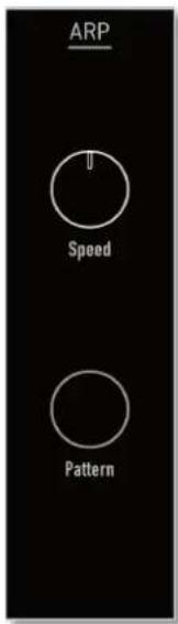
Based on the Speed setting, the ARP button flashes rhythmically (once per quarter of as 4/4 bar).
Pattern
Determines whether an internal rhythm pattern is played and which one.
The Arpeggiator Display Parameters
➢ Press the ARP button above the display to show the Arp display pages. The current selected Arp page is shown in the upper right corner of the display, e.g. ARP>Main. Use the Sound/System encoder to scroll through the display pages.
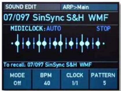
Arp Main display page
Both arpeggiator display pages show also a graphical representation of the selected arp pattern, the MIDI clock status and the current tempo.
Main Page
Here you find all parameters regarding the Arp settings.
MODE
Determines the arpeggiator mode:
• If off is selected, the arpeggiator is deactivated.
- If Normal is selected, the arpeggiator works as follows: When you press a note or a chord on the keyboard, it is split up and repeated rhythmically. As soon as you release a note, it is re-moved from the arpeggio rhythm. Conversely, as soon as you add another note to the existing chord, it is inserted into the arpeggio. When you release all notes, the arpeggiator stops.
- If One Shot is selected, the arpeggiator splits up all played notes and plays back one arpeggio. After the arpeggio rhythm is played once, it is stopped automatically unless you hit a new chord. This mode is especially useful in a live performance where you might have to "synchronize" yourself. Just hit a chord at each new bar.
- If Hold is selected, the arpeggiator splits up all played notes and generates a continuous arpeggio even when the chord is released.
BPM
Same functionality as for the Speed panel parameter.
CLOCK
Determines the note value for whole notes to thirty-second notes. The basis is a 4/4 beat. Triplets (e.g. 1/8T) and dotted notes (e.g. 1/16.) are available for every value.
PATTERN
Same functionality as for the Pattern panel parameter.
Pattern Page
Here you find all parameters regarding the Arp pattern settings.
PLAYDIR
Determines the sequence of generated notes according to pitch.
Sound Parameters
- If Up is selected, the arpeggio starts at the lowest note and sweeps up through the notes until it reaches the highest note. It then starts at the bottom again.
- If Down is selected, the arpeggio starts at the highest note and sweeps down through the notes until it reaches the lowest note. It then starts at the top again.
- If Alt Up is selected, the arpeggio starts at the lowest note and sweeps up through the notes until it reaches the highest note. It then starts to sweep back down.
- If Alt Down is selected, the arpeggio starts at the highest note and sweeps up through the notes until it reaches the lowest note. It then starts to sweep back up.
- If Move Up is selected, the note list is played in the order as played on the keyboard.
RANGE
Determines the range of the single notes in octaves.
About Modulation Assignments
A modulation can be described as a signal-generating unit's influence upon a sound parameter. The terms used in this context are 'Source' and 'Destination'. There is no Modulation matrix as in our other Waldorf synthesizers. We made a conscious decision to set up the modulation facilities directly on the corresponding display page, i.e. in the respective sections as Oscillators, VCF or VCA. This is a tribute to the famous Waldorf Microwave synthesizer.
Keep in mind that some modulation sources are hardwired, for example the Wave envelope or the Filter envelope. Therefore, you find an amount control in the corresponding section of the user interface, e.g. the Env Amt knobs.
Each audio module has a few pre-configured modulation modules. The oscillator, for instance, uses the pitch-bend as a standard modulation input while the filter has the filter envelope regularly assigned. These modulation modules can be programmed in their amplitude only; of course a settings of off will effectively disconnect each modulation input.

Sound Parameters
You will find the following pre-configured modulations:
For oscillators:
- Pitch bend range
For Wavetables:
• Wave envelope (amount and velocity)
• Key tracking
For VCF
• VCF envelope (amount and velocity)
• Key tracking
For VCA
• VCA envelope (amount and velocity)
• Key tracking
On top of this, most modules have routable modulation inputs; this is true for both the audio as well as the modulation inputs themselves. With a routeable modulation input, you can determine both the mod control module used as the modulation source as well as its amount. There are two different kinds of such modulation inputs:
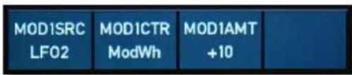
Modulation assignment with Source, control and amount
Sidechain modulation-input (called MOD CTR): Allows you to cross-modulate two modulation modules. This way you can control the effect of the source by using different mod control sources.
Regular modulation-input (called MOD SRC): Works as straightforward as you would expect.
The Modulation Amount (MOD AMT) can be set to both positive and negative values. The amount itself sets the peak of the modulation; for an ADSR envelope it would be the level reached by the attack time. A negative value will invert the output of the modifying module; a ADSR envelope, for instance, would be turned upside down, starting and ending at the highest level; a LFO would be 180 degrees out of phase with the original signal produced by the mod control module.
The Multi Mode
M offers a 4 part Multi mode. Each sound in a Multi setup based on a so-called Part. A Part offers some additional settings that belong to the Multi and therefore are not stored in the Sound program itself. The Multi setup is called Arrangement.
The are two main reasons for using a Multi arrangement:
- Using M with a sequencer. In that case you want to use several Sound programs at once, each assigned to a different MIDI channel.
- Building layered sounds. By doing this you can get interesting combinations e.g. a chord sound that fades into a string pad.
Of course, you can use both methods in combination.
How to enter the Multi Mode
➢ Press the Single/Multi encoder to enter the Multi mode. The LED near to the dial lits in white. If you want to return to single mode, press the dial again.
Use the Single/Multi encoder to select the desired Multi arrangement. Press Recall to load it.
Use the Bank/Part buttons to switch between the 4 multi parts. The current part number is shown in the upper left ordner of the display (e.g. Part 3).
➢ Press Shift + Mode/Map buttons to enter the Multi Map Edit pages. Use the Sound/System encoder to navigate through these pages. Press Cancel to exit the Multi Map Edit pages.
The Multi Map Edit Display Pages
The current selected Multi Map page is shown in the upper right corner of the display, e.g. Multi>Main
Keep in mind that the parameters of the Multi can be set up for all 4 parts individually. So you need to make extensive use of the Bank/Part buttons to switch between the parts.

The Multi Mode
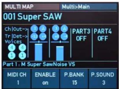
Multi Main display page
All Multi map display pages give you also information about all parts and their basic settings.
Main Page
Here you find all parameters regarding basic part settings.
MIDI CH
Determines the MIDI receive channel for the current Part.
ENABLE
Determines whether the current Part is disabled or enabled.
P.BANK
Selects the bank from which the sound program is taken.
P.SOUND
Selects the Part's sound program.
Pan & Out Page
Here you find all parameters regarding volume and panning settings.
P.VOL
Determines the volume for the current Part.
The overall volume is set with the Master Volume dial. The attenuation chain is Instrument VCA volume setting > Part Volume setting > Master Volume setting,

The Multi Mode
PAN
Determines the position of the current Part within the stereo panorama. The value range extends from L-64, which means far left, over the center position to R-63, which means far right.
PANMOD
This setting decides whether a panning modulation (as set in the part's chosen sound patch) is applied for the current Part or not. When set to off, no panning modulation is done at all.
AUXOUT
Selects one of the 4 AUX audio outputs on which the current Part's signal will appear.
Limit Page
Here you find all parameters regarding key zone and velocity settings.
K.LIM L
You can restrict the key range used for the current Part's tone generation. Only notes with a key number higher or equal to the selected value are passed through. Set this parameter to C#-2 if you want to use the full keyboard range.
K.LIM H
Counterpart to the K.LIM L parameter. Only notes with a key number lower or equal to the selected value are passed through. Set this parameter to C7 if you want to use the full keyboard range.
V.LIM L
This parameter allows you to limit the velocity range in which the current Part is played. Only notes with a velocity higher or equal to the selected value are passed through. Set this parameter to 1, if you want to turn velocity switching off.
V.LIM H
Counterpart to the V.LIM L parameter. Only notes with a velocity lower or equal to the selected value are passed through. Set this parameter to 127, if you want to turn velocity switching off.
Tuning Page
Here you find all parameters regarding the tuning settings.

TRANSP
Allows one to transpose the current Part in steps of a semi-tone.
DETUNE
Fine-tunes the current Part in increments of 64ths of a semitone.
V.CURVE
Determines the dynamic response curve of the incoming MIDI velocity for the current Part. By selecting one of the 10 curves, the dynamic velocity will adapt on that. This option is useful, e.g. in a layered Multi arrangement, to highlight one part's sound over another on high/low key velocities.
You can find diagrams of the available velocity curves in the Appendix of this manual.
LockVCF
Locks all 5 VCF controls for any another active and currently controlled part. I.e., when those controls are used for part 1 (active), all other parts will be affected of the same settings if LockVCF of any inactive (not currently controlled) part is on. This is helpful for simultaneous controlling of VCF parameters in a layered Arrangement.
Voice Allocator Page
Here you find all parameters regarding the voice allocation settings.
Here are some global rules for the voice allocation:
1) The Parts have a voice priority from 1 to 4, according to their numbers. E.g. by allocating voices, Part 1 has a higher priority than Part 2, part 2 a higher priority than part 3, and so on.
2) If there are less than 8 (16 with the optional voice expansion) voices set as "dedicated", all unused voices will belong to Part 1.
3) If the sum of voices, set as dedicated, is more than 8 (or 16 with the expansion) for some top parts (for example, Part 1 and 2 has each 4 voices assigned and the unit has a total of 8 voices), the Parts 3 and 4 may be "voiceless" if the priority Parts used all voices.
4) If a Part has a dedicated AUX output assigned, these voices reserved for a Part mandatory with higher priority, and overrides the "higher" Parts Min.Voices setting. This can be recognized as protection from stealing the voices between Parts.
The Multi Mode
V.STEAL
Activates/deactivates the voice stealing option.
V.TOTAL
Sets the minimum guaranteed polyphony for the part, according to the voices allocation rules.
Multi arrangements can be stored in the same way as sound programs.
The part related sound patches are NOT stored together with the Multi Arrangement. The sound of one particular part in the Arrangement is effectively a link to the certain chosen sound from a certain chosen sound bank. That means, if a sound patch or a soundbank will be replaced, a arrangement will sound incorrectly. Please take this into account, when changing existed sound patches or sound banks.

The System Menus
The system parameters are settings that influence the M's general response. These are determined separately from the programs and stored in a special memory location. System parameters are stored automatically when switching off the device.
➢ Press the Sound/System encoder to enter the System menu mode. The LED near to the dial lits in white. If you want to return to Sound mode, press the dial again.
In system menu mode, the ARP and LFO buttons are used to switch between System Settings and System Operations.
Use the dials below the display to navigate through the current display page. For example, when on Settings 1 System page, use dial 1 to select the desired option. With dial 2, change the value/setting to you needs. Press the Save button to store your settings.
The Settings Menu Pages
➢ Press the ARP button to enter the Settings menu mode. The button lits in white.
Settings 1 System Page
Here you find all parameters regarding the System settings.
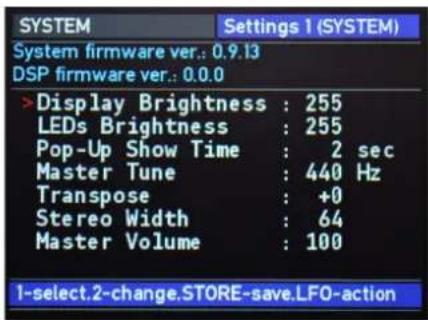
Display Brightness
Determines the brightness of the display.
The System Menus
LEDs Brightness
Controls the brightness of all LEDs.
Pop-Up Show Time
Here you can determine how long a popup message will be shown in the display.
Master Tune
Determines the M's overall pitch. The value specified here is the reference pitch for MIDI note A3. The default setting is 440 Hz, which is commonly used by most instruments.

You should only change this setting if you really know what you're doing. You will have to adjust all your other instruments, too. Don't forget to set it back again!
Transpose
Allows to set a global pitch transpose for all programs of the M.
Stereo Width
Reduces the stereo with from maximum 64 to mono, if desired.
Master Volume
Sets the basic master volume of all M programs for all outputs.
Settings 2+3 MIDI 1/2 Pages
Here you find all parameters regarding the global MIDI settings.
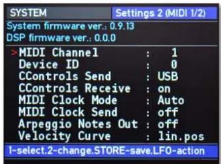
MIDI Channel
Sets the basic send and receive channel for the. This setting is valid for all Sound programs in Single mode.

Device ID
Defines the device identification number for system exclusive data transmission. Transmission will only be executed successfully if the sender and receiver setting coincide. Device ID 127 is a so-called broadcast ID that addresses all connected M units. M can receive this from other devices, but cannot send it itself. This function is limited to special computer software.
CControls Send
Here you can determine, where all MIDI Control Change (MIDI CC) data is being sent out for the panel pots, some buttons, and encoder. If offist selected, no data is send out. DIN means via DIN MIDI only, USB means via USB MIDI only and DIN+USB means on both MIDI ports.
In the Appendix on page 82 you will find a MIDI controller layout list for M.
CControls Receive
Here you can determine, if MIDI Control Change (MIDI CC) data is received. If off ist selected, all incoming MIDI CC data will be ignored.
MIDI Clock Mode
Determines how M reacts to incoming MIDI Clock messages.
- Int means that M doesn't react to incoming MIDI Clock. M only syncs to its own tempo base that is set by the Speed dial or the BPM parameter which can found on the Arp display page.
- Ext means that M automatically syncs to incoming MIDI Clock if it is sent by an external device like a sequencer or drum machine.
- Auto means that M automatically syncs to incoming MIDI Clock if it is sent by an external device, but uses its own tempo, if no MIDI clock signal is present.
MIDI Clock Send
Enables or disables the sending of MIDI clock for the desired MIDI ports (DIN, USB or DIN+USB). This setting should be enabled in those cases, where you want to use the M's arpeggiator as master for controlling the tempo.
The System Menus

When MIDI Clock Send is enabled while the M's DIN or USB MIDI In and Out are connected to your sequencer, you will probably get a MIDI loop. A total hangup of your system may result. Ensure to disable the M's MIDI clock sending feature in such a case.
Arpeggio Notes Out
Here you can determine, where all notes generated by the Arpeggiator is being sent out. If off ist selected, no arp note data is send out. DIN means via DIN MIDI only, USB means via USB MIDI only and DIN+USB means on both MIDI ports.
Velocity Curve
Determines the overall dynamic response curve of the incoming MIDI velocity for the Sound programs. By selecting one of the 10 curves, the dynamic velocity will adapt on that.

You can find some diagrams of the available velocity curves in the Appendix of this manual.
CC Controller A...D & W...Z
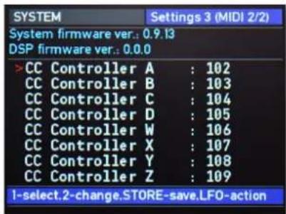
These parameters are used to define modulation sources that are freely definable MIDI controllers. Each value represents a MIDI controller number that is used when you assign its parameter as modulation source.

Example: You want to control the LFO1 speed via MIDI controller #102. To do so, set CC Controller A to 102 first. Then, navigate to the LFO1>Mod display page and select Ctr A as RTEMODS (Rate modulation source) and finally apply an suitable RTEMODA amount. In the same way you can the other Controller B..D and W...Z for further assignments.

Settings 4 User Page
Here you find all parameters regarding the User wavetable settings.
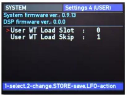
User WT Load Slot
Defines the User wavetable slot where to load user wavetables from SD card. This prevents from overwriting existing user wavetables.
User WT Load Skip
Determines, how exactly M imports the user wavetable. Imagine 256 waves of a user wavetable. As M offers only 64 waves in a wavetable, this user wavetable cannot be loaded completely. Depending on the User WT Load Skip setting, it will be read as followed:
- Setting is 1 - no skips, first 64 waves read and stored into the internal Waldorf M user wavetable slot.
- Setting is 2 - each second wave will be skipped, half of the first 128 waves read and stored into internal Waldorf M user wavetable slot.
- Setting is 4 - each fourth wave will be read (i.e. 3 skipped), a quarter of the 256 waves read and stored into internal Waldorf M user wavetable slot.
If a user wavetable contains fewer than 64 waves, it will be read out according to the WT Loading Skip setting rules and all waves in the wavetable after the last actually read wave will be filled with the same samples as the last wave read.
For example, if the user wavetable contains 32 waves, and WT Loading Skip setting is 1, the waves in the positions 0...31 in the user wavetable will be populated with these 32 waves, reading from the user wavetable file. All waves in the positions of 32..63 in the wavetable will be populated with the same samples as it was populated for wave 31.

VCF Tune Mainboard Page
Here you find the options for tuning the VCF filter voices.

Warning! If one of the VCF tuning options is selected, M plays a tone for audible orientation. Please turn down the overall volume before.
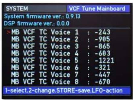
MB VCT TC Voice 1...8
Use the display encoder 1 to change the voice, it will stay at resonance mode to tune. Use encoder 2 to tweak coefficient (they are reverse-meaning, i.e. to tune higher, you need to set the coefficient LOWER and vice versa. Save the
tune coefficients with the settings by pressing Store. M will load your settings on start, so no need to retune the VCFs after fine-tuning anymore.
Please also remember about thermal drift, so at the start with cold VCFs they will be tuned higher on about 2 semitones. The best results could be achieved, when you will tune the unit after ca. 15-20 minutes of warming up.
The best way is to make VCF fine-tuned on this screen against C5 1042.5 Hz @ \~20C, is using software tuner. In that case, the settings Cutoff 64 / Resonance 127 / Key track 63 will exactly follow the equal-tempered scale within 4-5 octaves (from C2 to C7 roughly). Lower C2 will be under tune, higher C6 possibly C7 - over tune.

Of course, environment temperature plays a role. If your studio room is on the top floor and it's summer, we recommend to better tune the M in the night.

The System Menus
The Operations Menu Pages
➢ Press the LFO button to enter the Settings menu mode. The button lits in white.
System Operations Page
Here you find all options for loading/saving the M content.
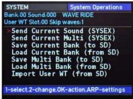
Send Current Sound (SYSEX)
Sends the currently loaded single sound program as MIDI SysEx dump by using the USB MIDI port.
Important note: When a sound program sysex message will be received by M, it will be immediately overwrite the current selected sound program.
Send Current Multi (SYSEX)
Sends the currently loaded Multi program as MIDI SysEx dump by using the USB or DIN MIDI port.
Save Current Bank (to SD)
Saves the currently loaded sound bank in the accordingly named file at the root directory of a connected SD Card (e.g., soundbank0010 for soundbank 10).
Load Current Bank (from SD)
Loads the currently chosen sound bank from the accordingly named file at the root directory of a connected SD Card.
Save Multi Bank (to SD)
Saves all multi bank in the accordingly named file at the root directory of a connected SD Card.
The System Menus
Load Multi Bank (from SD)
Loads all Multi banks from the accordingly named file at the root directory of a connected SD Card.
Import User WT (from SD)
M is capable load user wavetables directly from SD Card. The convention of the files, which contain wavetables is simple. The wavetable file can contain waves from 1 up to 256. Each wave is a sequence of 256 signed 8-bit samples. There is no header or anything else at the beginning of the file and this file should be named wtslotXX where XX stands for numbers from 00 to 31 according to the slots in the Waldorf M.
System Service Page
Here you find further system options.
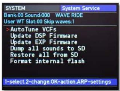
AutoTune VCFs
The analog filters of M can be improperly tuned due to the temperature drift. If there is some big detune between the voices, you should perform this Auto tune option. It is strongly recommended to do this 15-20 minutes after switching on the Waldorf M, since only then will the temperature of the analog circuits in the device stabilize.
AutoTune may produce improper/not enough precise results. It is recommend to check and perform a manual fine tune after it. You find a sound patch for this in bank 07, sound 128 called "VCF Track Tune".
The System Menus
Update DSP Firmware
Read more about DSP firmware updates in the corresponding chapter of the Appendix.
Update EXP Firmware
Read more about EXPansion firmware updates in the corresponding chapter of the Appendix.
Dump all Sounds to SD
Saves all 16 sound banks and multi bank on the SD Card. The files will be written on the root directory of the SD Card and will overwrite the content of previously located files with the same names.
Restore all sounds form SD
Restores all 16 sound banks and multi bank from the files on a connected SD Card. Use this option for factory restore /creating internal storage files in combination with the next action. If some appropriately named file will not be found in the root directory of the SD Card during the recovery process, M just creates this sound bank or multi bank in the internal flash, populated with defaults.
Format internal flash
Completely erase all content of internal flash, including user wavetables and system settings.

Important note: Normally, you should not perform this action as it acts immediately and without any possibility to restore the valuable content of internal flash! Use it with the previous option (Restore all sounds from SD) as a part of full factory init process.

Appendix
Updating the Firmware & DSP Firmware
M has a service-friendly feature that makes it possible to update the system and/or DSP firmware by user.
All firmware updates come in the form of a .dfu file that can be copied on every FAT file system formatted SD card. The fastest way to get this file is by downloading it from our web site at:
www.waldorfmusic.com/m
To update M's firmware:
- Copy the .dfu file onto the root directory of a SD card.
- Insert the SD card into M's card slot.
- Switch your M off.
- Hold down both Bank/Part buttons and switch M on again.
- The firmware update should be recognized automatically. To start the firmware update process, press the OK button.
• After the firmware is installed correctly, M burns it into its FLASH memory.
- Wait until the operation is completed. If updating was successful, the M will perform a system reset and start by pressing the OK button again.
Sometimes, a dedicated update of the internal DSP firmware could be necessary.
To update M's DSP/EXP firmware:
- Copy the .dfu file onto the top-level of a suitable SD card. Insert the SD card into M's card slot.
- Press the Sound/System encoder to enter the System mode. The LED on the right of the dial lits in white.
- Click on the LFO button to switch to the System Operation pages.
- Use the Sound/System encoder to navigate to the System Service page, where the Update DSP/EXP Firmware command is located. Use the silver display dial 1 to select this command.
- Press the OK button and follow the instructions.
Do not under any circumstances turn off M while the update process is in progress. A complete loss of data may occur and it will be impossible for you to make your machine work again!
FAQ - Frequently Asked Questions
How do I make a backup of my patches?
Please go to System > Operations > Dump all sounds to SD. Keep in mind that you need a suited SD card for that procedure.
My SD card is not recognized by M
Please make sure the SD card is turned upside up and inserted properly. Also, it should be FAT or FAT32-formatted. There are no known incompatibilities with any SD card, except of older SDSC/MMC rev 1. standard SD cards (produced usually before 2005 and with a capacity of 32 - 128 Megabytes).
M doesn't recognize the DSP or Firmware update file, although it definitely is located in the top directory of the SD card.
Please allow a bit of time, sometimes M needs up to a minute after inserting the SD before it recognizes the card and the update file. In rare cases, you may try two or three times. Opening the zip file isn't enough, the .dfu files need actually be unpacked. Maybe your file got corrupted during download, please try downloading it again.
My device isn't recognized via USB.
• Make sure that your device is connected to your computer directly and not through a hub.
- Use the computer's rear USB, not front USB connection.
- Disconnect all other USB devices from your computer which aren't needed at the moment.
- Change the USB cable or try from a different computer.
- On macOS: Click on About this Mac in the Apple menu. Select System Report. Go to the Hardware dropdown menu on the left and unfold it. Select USB. Check if your device is listed there.
- On Windows: Press the Win key + R. Enter devmgmt.msc and press OK. Check if your device is listed there. If it shows up as an "Unknown Device" and if there's a black and yellow warning sign, deinstall the driver. Then unplug the instrument, reboot your machine and plug it back in.
M has crashed!
First, please update M's Host and DSP firmware. Sometimes we release a new firmware and we definitely recommend going for it. The procedure takes less than a minute. M's firmware is really stable so crashes rarely occur.
Are the outputs from my device balanced or unbalanced?
Appendix
This device has unbalanced outputs. We recommend using it with unbalanced cables.
Does my device send audio via its USB connection?
No. This device only sends and receives MIDI via USB. Transferring audio or files isn't possible.

A Short Introduction in Wavetable Synthesis
The sound generation of the wavetables in M is based on wavetable synthesis.
The following overview explains how the wavetable synthesis works:
A wavetable is a list consisting of 64 waveforms. Each waveform is classified by its own very special sound character. Some wavetables contain waveforms with a similar sound character in between, others include waves with extremely different timbres.
You will notice, that the upper three entries in the wavetable (position 61, 62 and 63) consist of the classic analog type waveforms triangle, pulse and sawtooth. These three waves are identical in every wavetable. You can always use these classic synthesizer waves, independent of which wavetable is currently selected.
Both oscillators of one M's voice use a common wavetable. However each oscillator can play a different waveform inside the list. E.g. oscillator 1 can play a sine wave from position 1 of the list while oscillator 2 is playing a sawtooth wave from position 63.
The main difference of wavetable synthesis in comparison with other sound-generation principles is the ability to not only to play one waveform per oscillator but also to step through the wavetable via different modulations, thereby creating wavetable sweeps. The results can be dramatic - much more so than anything any sample playback-based system could ever produce.
This principle offers powerful capabilities. To give some examples:
• Each note on a keyboard can access a different wave of a wavetable.
- An LFO can modulate the position within the wavetable. You can create subtle to drastic sound changes.
- User-selected controllers, such as the mod wheel, can change the position within the wavetable. When you turn the wheel while playing a chord, each note's wave will be modified instantly.
You should keep the following sentence in mind:
A wavetable is a list with two or more waves, among which you can move at will.
Modulating Waves over time
The graphic below shows a wavetable with 60 waves and some of its included waves from position 0 to 59 on the vertical axis. The horizontal axis represents the audio
Appendix
signal that is generated and the diagonal line in the graphic shows the attack stage over time.
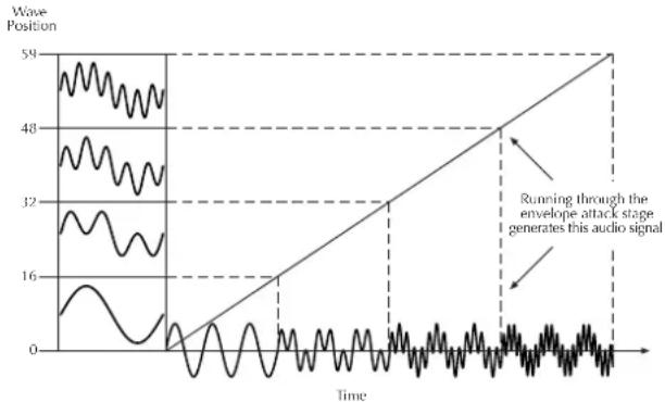
line
| Time | Wave Position | |------|---------------| | 0 | 0 | | 1 | 16 | | 2 | 32 | | 3 | 48 | | 4 | 59 |As soon as you play a note the envelope moves through the wavetable positions generating different waveforms over time.
The decay stage would move through these waves in the opposite direction while ultimately holding a certain wave at its sustain stage. When you release the note, the envelope decays to zero.
Most wavetables are created so that they start with a hollow wave at position 0 and go through increasingly brighter waves up to maximum position. This results in a behaviour similar to a low pass filter so that they can be conveniently controlled by an envelope.
If Attack is 0 and Decay set to a medium value you get a percussive sound; if you turn up the attack, you get a soft-sounding start.
You can also use an LFO to modulate the wavetable position and, depending on the selected LFO Shape, you might get a wave scanning that goes back and forth (triangle) only into one direction followed by a hard reset to the origin (triangle with maximum Symmetry) or between only two waves (square).
Exceeded Waves of a Wavetable
Of course you can combine envelope and keytrack modulations or add other modulation sources. All these modulations will be added so that maybe the end or the beginning of a wavetable could be exceeded.

Appendix
Velocity Curve Maps
M offers 10 different velocity curve maps, which are displayed on the following pages.
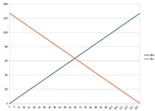
line
| x | In+ | In- | | ---- | ---- | ---- | | 1 | 0 | 130 | | 2 | 20 | 110 | | 3 | 40 | 90 | | 4 | 60 | 70 | | 5 | 80 | 50 | | 6 | 100 | 30 | | 7 | 120 | 10 | | 8 | 140 | 0 |Linear + and Linear - Velocity Curves
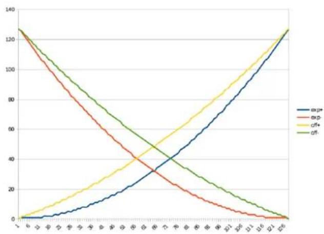
Exponential +/- and C/F +/- Velocity Curves

Appendix
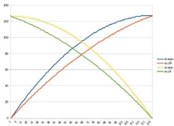
line
| X | m.agg+ | m.cif+ | m.exp- | m.cif | | ---- | ------ | ------ | ------ | ----- | | 1 | 0 | 0 | 125 | 125 | | 2 | 20 | 10 | 120 | 120 | | 3 | 40 | 20 | 115 | 115 | | 4 | 60 | 30 | 110 | 110 | | 5 | 80 | 40 | 105 | 105 | | 6 | 100 | 50 | 100 | 100 | | 7 | 110 | 60 | 95 | 95 | | 8 | 120 | 70 | 90 | 90 | | 9 | 125 | 80 | 85 | 85 | | 10 | 130 | 90 | 80 | 80 | | 11 | 135 | 100 | 75 | 75 | | 12 | 138 | 110 | 70 | 70 | | 13 | 140 | 120 | 65 | 65 | | 14 | 142 | 130 | 60 | 60 | | 15 | 143 | 140 | 55 | 55 | | 16 | 144 | 150 | 50 | 50 | | 17 | 145 | 160 | 45 | 45 | | 18 | 146 | 170 | 40 | 40 | | 19 | 147 | 180 | 35 | 35 | | 20 | 148 | 190 | 30 | 30 | | 21 | 149 | 200 | 25 | 25 | | 22 | 150 | 210 | 20 | 20 | | 23 | 151 | 220 | 15 | 15 | | 24 | 152 | 230 | 10 | 10 | | 25 | 153 | 240 | - | - | | 26 | 154 | 250 | - | - | | 27 | 155 | 260 | - | - | | 28 | 156 | 270 | - | - | | 29 | 157 | 280 | - | - | | 30 | 158 | 290 | - | - | | 31 | 159 | 300 | - | - | | 32 | 160 | 310 | - | - | | 33 | 161 | 320 | - | - | | 34 | 162 | 330 | - | - | | 35 | 163 | 340 | - | - | | 36 | 164 | 350 | - | - | | 37 | 165 | 360 | - | - | | 38 | 166 | 370 | - | - | | 39 | 167 | 380 | - | - | | 40 | 168 | 390 | - | - | | 41 | 169 | 400 | - | - | | 42 | 170 | 410 | - | - | | 43 | 171 | 420 | - | - | | 44 | 172 | 430 | - | - | | 45 | 173 | 440 | - | - | | 46 | 174 | 450 | - | - | | 47 | 175 | 460 | - | - | | 48 | 176 | 470 | - | - | | 49 | 177 | 480 | - | - | | 50 | 178 | 490 | - | - | | ... (multiple lines) represent the actual values from the original data series. The values are estimated based on the provided code.Mirrored Exponential +/- and C/F +/- Velocity Curves
Modulation Sources and Destinations
Modulation Sources
| Source | Description |
| off | No modulation source |
| ModWh | Modulation wheel (CC #1) |
| Pbend | MIDI Pitchbend signal |
| LFO 1 | LFO 1 signal |
| LFO 2 | LFO 2 signal |
| AmpEnv | Amplifier Envelope signal |
| Flt Env | Filter Envelope signal |
| WavEnv | Wave Envelope signal |
| Free Env | Free Envelope signal |
| LFO1Env | Envelope of LFO1 |
| Sus Pdl | MIDI Sustain pedal (CC #64) |
| Vol Ctr | MIDI Volume Controller (CC #7) |
| Pan Ctr | MIDI Foot Controller (CC #10) |
| BrthCtr | MIDI Breath Controller (CC #2) |
| FootCtr | MIDI Foot Controller (CC #4) |
| ExprCtr | MIDI Expression pedal (CC #11) |
| Ctr A...D | Assignable Controller A...D |
| Ctr W...Z | Assignable Controller W...Z |

Appendix
| KTrack | MIDI Note number |
| Velo | MIDI Velocity |
| RelVel | MIDI Release Velocity |
| AftTch | Keyboard Pressure Data |
| PolyPress | Keyboard Poly Pressure Data |
| GI.LFO | Global LFO signal |
| MAX | Fixed value of 127 |
| min | Fixed value of 0 |
Modulation Destinations
All destinations are available through the corresponding Mod menu pages.
| Destination | Description |
| Osc1 & Osc2 Pitch | Pitch of Oscillator 1 & 2 |
| WAV1 & WAV2 Position | Wavetable Position of Oscillator 1 & 2 |
| Osc1 & Osc2 Mix | Level of Oscillator 1 & 2 |
| Noise Mix | Level of Noise generator |
| Ring Mod Mix | Level of Ring modulator |
| VCF Cutoff | Filter Cutoff frequency |
| VCF Resonance | Filter Cutoff resonance |
| Pan Mod | Stereo panning |
| VCA | VCA Level |
| LFO1 | Rate of LFO1 |
| VCF Env Delay | Delay of VCF Envelope |
| VCF Attack | VCF Attack time |
| VCF Decay | VCF Decay time |
| VCF Sustain | VCF Sustain level |
| VCF Release | VCF Release time |
| VCA Attack | VCA Attack time |
| VCA Decay | VCA Decay time |
| VCA Sustain | VCA Sustain level |
| VCA Release | VCA Release time |
| WAVE Time | Wave Envelope Times |
| WAVE Level | Wave Envelope Levels |
| FREE Time | Free Envelope Times |
| FREE Level | Free Envelope Levels |
Appendix
MIDI CC Messages Support
Waldorf M supporting the classic MIDI CC layout as it was defined by the Waldorf Microwave II XT synthesizers (with the addition of CC#63 to select a wavetable for OSC2).
Below you find the mapping of the CC messages of the supported sound parameters. Also, if a sound parameter has a dedicated panel control, the Waldorf M will send out a MIDI CC Message when editing this parameter. If available, this refers to the corresponding parameter.
| MIDI CC Number(s) | Sound Parameter(s) |
| 5, 65 | Glide Rate, Glide Enable |
| 14, 15, 16, 17 | Attack, Decay, Sustain, Release of EG1 (VCF) |
| 18, 19, 20, 21 | Attack, Decay, Sustain, Release of EG2 (VCA) |
| 24, 25 | LFO1 Rate, LFO1 Shape |
| 26, 28 | LFO2 Rate, LFO2 Shape |
| 33, 34, 35 | OSC1 Octave, OSC1 Semitone, OSC1 Detune * |
| 38, 39, 40 | OSC2 Octave, OSC2 Semitone, OSC2 |
| Detune * | |
| 41 | OSC2 Sync to the OSC1 |
| 45, 46, 47, 48 | OSC1 Level, OSC2 Level, Ringmod Level, Noise Level |
| 50, 56 | VCF Cutoff, VCF Resonance |
| 51, 52, 53 | VCF Keytrack, VCF EG Amount, VCF EG Velocity * |
| 57 | Master Volume (VCA Volume in Single Mode) |
| 58, 59 | VCA EG Amount, VCA EG Velocity * |
| 70, 71 | Wavetable OSC1, Wave OSC1 |
| 63, 78 | Wavetable OSC2, Wave OSC2 |
| 73, 79 | Wave EG to Wave OSC1, Wave EG to Wave OSC2 * |
| 85, 86, 87, 88 | Free EG Time 1, Free EG Level 1, Free EG Time 2, Free EG Level 2 |
| 89, 90, 91, 92 | Free EG Time 2, Free EG Sustain Level, Free EG Release Time, Free EG Release Level |
* Positive shifted: Means, that the parameter, which works in a range from -64...0...+ 63 is mapped to the standard 0..127 MIDI value range by adding 64 to it.

Appendix
Technical Data
Power Supply
Supply Voltage Input 100 - 240 V AC / 50-60 Hz
Nominal Voltage Output 12 V DC
Maximum current consumption: 1.8 A max.
Dimensions and Weight
Width: 440 mm
Depth: 305 mm
Height (including knobs): 85 mm
Total weight: 5.7 kg

waldorf
83 M Manual
Appendix
Glossary
Aftertouch
The majority of contemporary keyboards are capable of generating aftertouch messages. On this type of keyboard, when you press harder on a key you are already holding down, a MIDI Aftertouch message is generated. This feature makes sounds even more expressive (e.g. through vibrato).
Aliasing
Aliasing is an audible side effect arising in digital systems as soon as a signal contains harmonics higher than half the sampling frequency.
Amount
The extent to which modulation influences a given parameter.
Amplifier
An amplifier is a component that influences the volume level of a sound via a control signal. This control signal is often generated by an envelope or an LFO.
Arpeggiator
An arpeggiator is a device that splits an incoming chord into its individual notes and repeats them rhythmically. Most arpeggiators feature different sequence modes to cover a wide range of applications. Typical controls for an arpeggiator are the octave range, the direction, the speed and the clock, which means the repetition interval. Some arpeggiators also feature preset or programmable rhythm patterns.
Attack
An envelope parameter. 'Attack' is a term that describes the ascent rate of an envelope from its starting point to the point where it reaches its highest value. The Attack phase is initiated immediately after a trigger signal is received - i.e. after you play a note on the keyboard.
Clipping
Clipping is a sort of distortion that occurs when a signal exceeds its maximum value. The curve of a clipped signal is dependent of the system where the clipping takes place. In the analog domain, clipping effectively limits the signal to its maximum level. In the digital domain clipping is similar to a numerical overflow and so the polarity of the signal's part above the maximum level is negated.

Appendix
Coffee Filter
A coffee filter is a coffee-brewing utensil, usually made of disposable paper. It is part of an essential toolkit for survival when working with the Waldorf M.
Control Change (Controllers)
MIDI messages enable you to manipulate the response of a sound generator to a significant degree.
This message essentially consists of two components:
- The Controller number, which defines the element to be influenced. It can be between 0 and 120.
- The Controller value, which determines the extent of the modification.
Controllers can be used for effects such as slowly swelling vibrato, changing the stereo panorama position and influencing filter frequency.
Decay
'Decay' describes the descent rate of an envelope once the Attack phase has reached its zenith and the envelope drops to the level defined for the Sustain value.
Envelope
An envelope is used to modulate a sound-shaping component within a given time frame so that the sound is chan-
ged in some manner. For instance, an envelope that modulates the cutoff frequency of a filter opens and closes this filter so that some of the signal's frequencies are filtered out. An envelope is started via a trigger – usually a fixed trigger. Normally the trigger is a MIDI Note. The classic envelope consists of four individually variable phases:
Attack, Decay, Sustain, and Release. This sequence is called an ADSR envelope. Attack, Decay, and Release are time or slope values, and Sustain is a variable volume level. Once an incoming trigger is received, the envelope runs through the Attack and Decay phases until it reaches the programmed Sustain level. This level remains constant until the trigger is terminated. The envelope then initiates the Release phase until it reaches the minimum value.
Filter
A filter is a component that allows some of a signal's frequencies to pass through it and dampens other frequencies. The most important aspect of a filter is the filter cutoff frequency. The most common type is the lowpass filter. A lowpass filter dampens all frequencies above the cutoff frequency.
Filter Cutoff Frequency
The filter cutoff frequency is a significant factor for filters. A lowpass filter dampens the portion of the signal that lies above this frequency. Frequencies below this value are allowed to pass through without being processed.
LFO
LFO is an acronym for Low-Frequency Oscillator. The LFO generates a periodic oscillation at a low frequency and features variable waveshapes. Similar to an envelope, an LFO can be used to modulate a sound-shaping component.
Low Pass Filter
Synthesizers are often equipped with a lowpass filter. A lowpass filter dampens all frequencies above its cutoff frequency. Frequencies below the cutoff point are not affected.
MIDI
The acronym MIDI stands for Musical Instrument Digital Interface. It was developed in the early 1980s so that diverse types of electronic musical instruments by different manufacturers could interact. At the time a communications standard for different devices did not exist, so MIDI was a significant advance. It made it possible to link any MIDI-equipped device with another through simple, uniform connections.
Essentially, this is how MIDI works: One sender is connected to one or several receivers. For instance, if you want to use a computer to play the Iridium, then the computer is the sender and the Iridium acts as the receiver. With a few exceptions, the majority of MIDI devices are equipped with two or three ports for this purpose: MIDI In, MIDI Out and in some cases, MIDI Thru. The sender transfers data to the receiver via the MIDI Out jack. Data is sent via a cable to the receiver's MIDI In jack.
MIDI Thru has a special function. It allows the sender to transmit to several receivers. It routes the incoming signal to the next device without modifying it. Another device is simply connected to this jack, thus creating a chain through which the sender can address a number of receivers. Of course it is desirable for the sender to be able to address each device individually. Consequently, there is a rule that is applied to ensure each device responds accordingly.
MIDI Channel
This is a very important element of most messages. A receiver can only respond to incoming messages if its receive
Appendix
channel is set to the same channel as the one the sender is using to transmit data. Consequently, the sender can address specific receivers individually. MIDI Channels 1 through 16 are available for this purpose.
MIDI Clock
The MIDI Clock message determines the tempo of a piece of music. It serves to synchronize processes based on time.
Modulation
Modulation influences or changes a sound-shaping component via a modulation source. Modulation sources include envelopes, LFOs, or MIDI messages. The modulation destination is a sound-shaping component such as a filter or an amplifier.
Note On / Note Off
This is the most important MIDI message. It determines the pitch and velocity of every generated note. The time of arrival is simultaneously the start time of the note. Its pitch is derived from the note number, which lies between 0 and 127. The velocity lies between 1 and 127. A value of 0 for velocity is similar to 'Note Off'.
Panning
The process of changing the signal's position within the stereo panorama.
Pitchbend
Pitchbend is a MIDI message. Although pitchbend messages are similar in function to control change messages, they are a distinct type of message. The reason for this distinction is that the resolution of a pitchbend message is substantially higher than that of a conventional Controller message. The human ear is exceptionally sensitive to deviations in pitch so the higher resolution is used because it relays pitchbend information more accurately.
Program Change
These are MIDI messages that switch sound programs. Program numbers 1 through 128 can be changed via program change messages.
Release
An envelope parameter. The term 'Release' describes the descent rate of an envelope to its minimum value after a trigger is terminated. The Release phase begins immediately after the trigger is terminated, regardless of the enve-
Appendix
lope's current status. For instance, the Release phase may be initiated during the Attack phase.
Resonance
Resonance is an important filter parameter. It emphasizes a narrow bandwidth around the filter cutoff frequency by amplifying these frequencies. This is one of the most popular methods of manipulating sounds. If you substantially increase the resonance, to a level where the filter begins self-oscillation then it will generate a relatively clean sine waveform.
Sustain
An envelope parameter. The term 'Sustain' describes the level of an envelope that remains constant after it has run through the Attack and Decay phases. Sustain lasts until the trigger is terminated.
System Exclusive Data
System exclusive data allow access to the heart of a MIDI device, enabling access to data and functions that no other MIDI messages are able to address. 'Exclusive' in this context means that this data pertains to only one device type or model. Every device has unique system exclusive data. The most common applications for SysEx data include transfer of entire memories and complete control of a device via a computer.
Trigger
A trigger is a signal that activates events. Trigger signals are very diverse. For instance, a MIDI note or an audio signal can be used as a trigger. The events a trigger can initiate are also very diverse. A common application for a trigger is use to start an envelope.
Volume
The term describes a sound's output level
USB
The Universal Serial Bus (USB) is a serial bus system to connect a computer with an external device. USB equipped devices can be plugged together while active. The recognition is made automatically.
Wave
In this context, a Wave is a digitally-memorized reproduction of one single wave pass insofar as it is identical to a sample that is looped after one single wave pass. In contrast to the samples in a sampler, all waves in Waldorf

Appendix
Wavetable synthesizers have the same lengths and are played back in the same pitch.
Wavetable
An oscillator shape in M is based on waveform sets called wavetables. You should think of these as a sequence of up to up to 64 single waves. This can be played back in a static way or played through dynamically, which results in their typically interesting sound transformations. If the waves do not differ much, then the wavetable will probably sound smooth and pleasant. If they have a completely different structure then this will result in wild spectral changes.

Product Support
Service & Repair
M does not contain any user-serviceable parts. If your M develops a fault or needs servicing, please refer to a Waldorf authorised service center. For more information, please ask your musicians dealer or your local Waldorf distributor.
Any Questions?
If you have any questions about your Waldorf product, feel free to contact us. We're here to help.
① Use the support form at our website. This is the most efficient and fastest way to contact us. Your questions will be forwarded immediately to the resident expert and you will quickly receive an answer.
support.waldorfmusic.com
② Send us a letter. It will take a bit longer, but it is just as dependable as an email.
Waldorf Music GmbH
Lilienthalstr. 7
53424 Remagen, Germany
③ Visit our support area at waldorfmusic.com

© 2021 Waldorf Music GmbH • All rights reserved
www.waldorfmusic.com
waldorf


- Foreword
- What to read?
- Hint
- We would like to thank
- Beta test
- M contains sounds from
- Specifications
- Control Features & Connections
- Front Panel
- Rear Panel Connections
- About this Manual
- Symbols
- Highlighted Control Features and Parameters
- General Safety Guidelines
- Suitable Operating Conditions
- Power Supply
- Operation
- Maintenance
- Proper Use
- Setup and Connections
- Setup
- Connections
- To connect the devices:
- The Rear Panel Connections
- Headphones Output and Headphone Volume
- Main Audio Output
- Stereo Aux Outputs A - D
- The USB 2.0 Connection
- SD Card Slot
- Physical Security
- Basic Operation
- Switching On / Off
- To switch M on:
- To switch M off:
- Master Volume
- The M Mode Pages
- The Option Button Section
- The Display and the 4 Encoders
- Loading Sound Programs
- To load a sound program:
- Editing Parameters
- Storing Sound Programs
- To save a sound program:
- Sound Parameters
- Global Voice Allocation
- PLAYMODE
- V.STEAL (Voice Stealing)
- Wavetable Oscillator Section
- The Oscillator Panel Parameters
- Wavetable (Outer black ring dial)
- Wave (Inner red dial)
- Semitone
- Octave
- Detune
- Env Amt (Envelope Amount)
- Sync Button (only available for Modern Mode)
- The Oscillator Display Parameters
- Osc 1 & 2 Tune Pages
- B.RANGE (Bend Range)
- Osc Mod 1 and 2 Pages
- MOD1SRC (Modulator 1 Source)
- MOD1CTR (Modulator 1 Sidechain Controller)
- MOD1AMT (Modulator 1 Amount)
- MOD2SRC (Modulator 2 Source)
- MOD2AMT (Modulator 2 Amount)
- MOD2QNT (Modulator 2 Quantize Depth)
- LINKMOD (only available for Oscillator 2)
- Osc Sync & Glide Page
- HSYNC (Hard Sync, only in Modern mode)
- GLIDE
- GL RATE
- Osc Tweaks Page
- FIXPITCH 1 / FIXPITCH 2
- OSCMODE
- ASICBUG (only in Classic mode)
- The Wave Display Parameters
- Wave Page
- WT (Wavetable)
- WAVE
- PHASE
- Wave Envelope Page
- ENVAMT (Envelope Amount)
- ENVVELO (Envelope Velocity)
- KTRACK (Keytracking)
- Wave Modulation Pages
- MOD1SCR
- MOD1CTR
- MOD1AMT
- MOD2SCR
- MOD2AMT
- LINKMOD (only available for Wave 2)
- Classic Mode vs. Modern Mode
- Oscillator Mixer (MIX) Section
- The Mix Section Panel Parameters
- Osc 1
- Osc 2
- Noise
- Ring Mod (only in Modern Microwave Mode)
- The Mix Display Parameters
- Levels Page
- OSC1LEV (Oscillator 1 Level)
- OSC2LEV (Oscillator 2 Level)
- NOISELEV (Noise Level)
- RMLEV (Ring Modulator Level)
- Mix Modulation Pages
- 01MODS
- 01MODA
- 02MODS
- 02MODA
- NSEMODS
- NSEMODA
- RMMODS
- RMMODA
- VCF Section
- The VCF Section Panel Parameters
- Cutoff
- Resonance
- Env Amt (VCF Envelope Amount)
- Velocity
- Keytrack
- The VCF Display Parameters
- General Page
- RESO
- ENVAMT
- ENVVELO
- KTRACK
- Mod1 Page
- Mod2/Reson Mod Page
- R.MODSRC
- R.MODAMT
- VCA Section
- The VCA Section Panel Parameters
- Env Amt
- The VCA Display Parameters
- Volume & Pan Page
- VOLUME
- PAN
- PANMODS
- PANMODA
- Env Page
- Mod2 Page
- Glide Section
- The Glide Panel Parameters
- Active Button
- Rate
- The Glide Display Parameters
- LFO Section
- The LFO Section Panel Parameters
- Shape
- The LFO Display Parameters
- LFO General (for LFO 1 and 2)
- SYMM
- HUMANZE
- Mod Page (only LF01)
- RTEMODS
- RTEMODA
- LEVMODS
- Sync&Env Page (only LF01)
- SYNC
- DELAY
- ATTACK
- DECAY
- Sync Page (only LF02)
- PH.SHIFT
- GLOBAL
- MIDISYNC
- MSYNCTO
- Envelopes Section
- The Envelope Section Panel Parameters
- Select Button
- Parameters for the VCF/VCA Envelopes
- Attack (for VCF & VCA Envelopes)
- Decay (for VCF & VCA Envelopes)
- Sustain (for VCF & VCA Envelopes)
- Release (for VCF & VCA Envelopes)
- Parameters for the Wave/Free Envelopes
- Time (for Wave & Free Envelopes)
- Level (for Wave & Free Envelopes)
- The Envelope Display Parameters
- General Pages (for VCF and VCA envelope)
- SUSTAIN
- RELEASE
- Delay Page (only for VCF envelope)
- DLYMODS
- DLYMODA
- A/D Mod Pages (for VCF and VCA envelope)
- ATKMODS
- ATKMODA
- DECMODS
- DECMODA
- S/R Mod Pages (for VCF and VCA envelope)
- SUSMODS
- SUSMODA
- RELMODS
- RELMODA
- Wave Env Points Pages (for WAVE envelope)
- P1...8 TIME
- P1...8 LVL
- Wave Env Mod Page (for WAVE envelope)
- TMEMODS
- TMEMODA
- LEVMODA
- Wave Env Loop Page (for WAVE envelope)
- K.OFF PT
- L.START
- LOOP
- Free Env Display Page (for Free envelope)
- REL.LOOP
- ENV Tweaks Display Page
- T/L MODE
- The Arpeggiator Section
- The Arp Section Panel Parameters Speed
- Pattern
- The Arpeggiator Display Parameters
- Main Page
- MODE
- BPM
- CLOCK
- Pattern Page
- PLAYDIR
- RANGE
- About Modulation Assignments
- The Multi Mode
- How to enter the Multi Mode
- The Multi Map Edit Display Pages
- MIDI CH
- ENABLE
- P.BANK
- P.SOUND
- Pan & Out Page
- P.VOL
- PANMOD
- AUXOUT
- Limit Page
- K.LIM L
- K.LIM H
- V.LIM L
- V.LIM H
- Tuning Page
- TRANSP
- V.CURVE
- LockVCF
- Voice Allocator Page
- V.STEAL
- V.TOTAL
- The System Menus
- The Settings Menu Pages
- Settings 1 System Page
- Display Brightness
- LEDs Brightness
- Pop-Up Show Time
- Master Tune
- Transpose
- Stereo Width
- Settings 2+3 MIDI 1/2 Pages
- MIDI Channel
- Device ID
- CControls Send
- CControls Receive
- MIDI Clock Mode
- MIDI Clock Send
- Arpeggio Notes Out
- Velocity Curve
- CC Controller A...D & W...Z
- Settings 4 User Page
- User WT Load Slot
- User WT Load Skip
- VCF Tune Mainboard Page
- MB VCT TC Voice 1...8
- The Operations Menu Pages
- System Operations Page
- Send Current Sound (SYSEX)
- Send Current Multi (SYSEX)
- Save Current Bank (to SD)
- Load Current Bank (from SD)
- Save Multi Bank (to SD)
- Load Multi Bank (from SD)
- Import User WT (from SD)
- System Service Page
- AutoTune VCFs
- Update DSP Firmware
- Update EXP Firmware
- Dump all Sounds to SD
- Restore all sounds form SD
- Format internal flash
- Appendix
- Updating the Firmware & DSP Firmware
- To update M's firmware:
- To update M's DSP/EXP firmware:
- FAQ - Frequently Asked Questions
- How do I make a backup of my patches?
- My SD card is not recognized by M
- M doesn't recognize the DSP or Firmware update file, although it definitely is located in the top directory of the SD card.
- M has crashed!
- Does my device send audio via its USB connection?
- A Short Introduction in Wavetable Synthesis
- Modulating Waves over time
- Exceeded Waves of a Wavetable
- Velocity Curve Maps
- Modulation Sources and Destinations
- Modulation Destinations
- MIDI CC Messages Support
- Technical Data
- Dimensions and Weight
- Glossary
- Aftertouch
- Aliasing
- Amount
- Amplifier
- Arpeggiator
- Clipping
- Coffee Filter
- Control Change (Controllers)
- Envelope
- Filter
- Filter Cutoff Frequency
- LFO
- Low Pass Filter
- MIDI
- MIDI Clock
- Modulation
- Note On / Note Off
- Panning
- Pitchbend
- Program Change
- System Exclusive Data
- Trigger
- USB
- Wavetable
- Product Support
- Service & Repair
- Any Questions?
- support.waldorfmusic.com
- Waldorf Music GmbH
Brand : WALDORF
Model : M Wavetable
Category : Synthesizer