
A-178 - Synthesizer Doepfer - Free user manual and instructions
Find the device manual for free A-178 Doepfer in PDF.


| Product Type | Theremin Voltage Source (Eurorack Module) |
| Width | 8 HP (40.3 mm) |
| Height | 128.5 mm (3U) |
| Depth | Approximately 20 mm (excluding power cable) |
| Weight | Approx. 100 g |
| Power Consumption | +12V: 30 mA, -12V: 10 mA (typical) |
| Antenna | Telescopic antenna included |
| CV Outputs | Two parallel CV outputs (0-10V), internally linked |
| Gate Output | Gate signal when CV exceeds threshold |
| Controls | Offset (null point adjustment), Threshold (gate trigger level) |
| Indicators | 2 LEDs for CV level, 1 LED for gate presence |
| Function | Generates control voltage proportional to hand proximity to antenna |
| Sensitivity | Adjustable via Offset control; internal trim inductor/potentiometer for coarse tuning |
| Polarity | Factory set: voltage rises as hand approaches; reversible via internal trim |
| Environmental Sensitivity | Affected by humidity and temperature; recalibration recommended each use |
| Mounting | Eurorack standard; recommended placement high in rack to avoid cable interference |
| Included Accessories | Module, antenna, power cable (assumed) |
| Maintenance | Check offset adjustment each use; clean antenna with dry cloth if necessary |
| Repair / Modifications | Internal trim accessible for offset/polarity adjustment; no other serviceable parts |
Frequently Asked Questions - A-178 Doepfer
User questions about A-178 Doepfer
0 question about this device. Answer the ones you know or ask your own.
Ask a new question about this device
Download the instructions for your Synthesizer in PDF format for free! Find your manual A-178 - Doepfer and take your electronic device back in hand. On this page are published all the documents necessary for the use of your device. A-178 by Doepfer.
USER MANUAL A-178 Doepfer
1. Introduction
Module A-178 (Theremin Voltage Source) produces a variable control voltage which gets bigger the closer your hand gets to its antenna.
You can use this control voltage in any modulation or control process, and thus have access to an extra system of real-time control in the synthesis process.
You use the Offset control to set the null point (zero) of the control voltage output. Two LEDs give a visual indication of the voltages produced.
The module also produces a gate signal at the gate output: the signal goes "high" as soon as a voltage is sensed which is above the threshold set with the Threshold control. An LED gives a visual indication of the presence of a gate signal.
This gives you the ability to produce a gate signal simply by moving your hand.
2. Overview
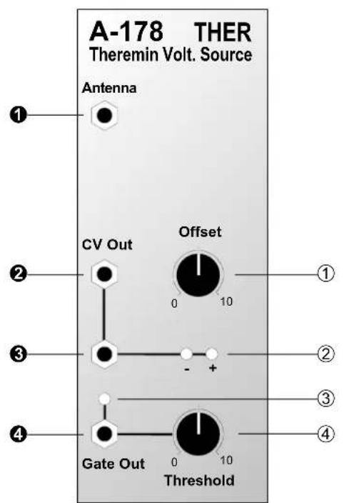
Controls:
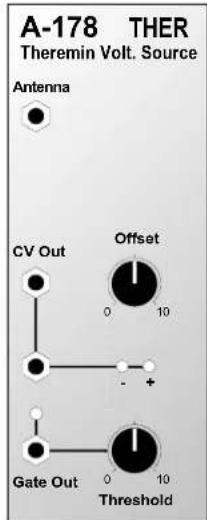
① Offset : control for setting the null (zero) point
② LEDs: LEDs to give a visual indication of the voltage present at output ②
③ LED : LED to give a visual indication of the presence of a gate signal at output 4
④ Threshold : control for setting the gate threshold
In / Outputs:
① Antenna : antenna input
②, ③ CV Out : CV outputs (internally linked)
④ Gate Out : gate output
3. Basic principles
The theremin acts as one plate of a capacitor and a human body as the other plate. Moving the hand towards and away from the antenna produces tiny changes in capacitance (so tiny that they're measured in the picoFarad range). The electronics within the theremin measure this change in the following way:-
The signal from an oscillator (whose frequency can be subtly adjusted with the offset control ①) is compared with the signal in another oscillating circuit, whose capacitor is made up of the antenna and an external object like the human body. If the capacitance is changed (by, e.g., moving your hand) the circuit's resonant frequency changes. This is measured, and converted into a control voltage.
Depending on the oscillator frequency, we may hit either the rising or the falling edge of the oscillating circuit's resonance - and thus produce respectively either rising or falling voltage as the hand gets closer to the antenna. The module is factory adjusted so that as the hand gets closer to the antenna, the voltage rises. This can be reversed if required, though.
4. Controls
① Offset
Control ① is used to adjust the null point, so that the control voltage at output ② is at 0 V, when the hand is some distance away from the antenna (more than about 30 cm).

Because this module, like all theremins, is very sensitive to fluctuations in humidity, temperature changes, etc., it's necessary to check adjustment each time you use it.
In addition to the offset control on the front panel, there's also an internal trim inductor for coarse adjustment of this offset frequency - see appendix on p. 8.
Using this trim pot for coarse adjustment may be necessary if, for instance, you install another antenna, and it's then no longer possible to set the null point with the front panel offset control; or you want to use the falling edge of the circuit resonance, so that the control voltage generated gets lower as you approach the antenna.
② LEDs
The LEDs ② indicate the state of the voltage at CV outputs ② and ③.
③ LED
LED ③ shows the presence of a gate signal at gate output ④.
④ Threshold
Using control ④ you set a threshold voltage for the CV output, above which a gate signal will be produced at output ④.
5. In / Outputs
① Antenna
Use socket ① to connect the antenna.

If you use any other antenna than the telescopic one provided, and find that it's not longer possible to set the null point with the offset control ①, then it may be necessary to use the internal trim pot (see page 3, and appendix, page 8).
② CV Out • ③ CV Out
CV outputs ② and ③ (internally linked) put out the theremin's voltage.
④ Gate Out
Socket ④ puts out the gate signal, whenever the voltage created by the theremin is greater than the threshold set with control ④. This gate signal can be used as a noise-gate or as a source of manually-triggered gates for other modules (see user examples).
6. User examples
Theremin module A-178 provides a further source of control for real-time sound manipulation and creation (so see also the suggestions in the manual for the Foot Controller, module A-177).
The change in voltage produced by your hand getting closer to the antenna can be used for all sorts of control or modulation:
- VCO pitch control
- VCA gain
• VCF cut-off frequency
• VCF resonance (with the A-121, 122 or 123) - VC-LFO frequency
• LFO modulation depth
Standard Theremin
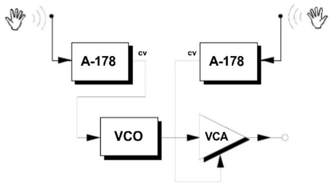
Fig. 1 shows how to use two A-178 modules to create a standard theremin. One hand controls the pitch of the VCO, and one controls the gain of the VCA.
flowchart
graph TD
    A["Input"] --> B["A-178"]
    B --> C["VCO"]
    C --> D["VCA"]
    D --> E["Output"]
    F["Input"] --> G["A-178"]
    G --> H["VCO"]
    H --> I["VCA"]
    I --> J["Output"]
    K["Input"] --> L["Input"]
    M["Input"] --> N["Input"]
    O["Input"] --> P["Input"]
    Q["Input"] --> R["Input"]
    S["Input"] --> T["Input"]
    U["Input"] --> V["Input"]
    W["Input"] --> X["Input"]
    Y["Input"] --> Z["Input"]
    AA["Input"] --> AB["Input"]
    AC["Input"] --> AD["Input"]
    AE["Input"] --> AF["Input"]
    AG["Input"] --> AH["Input"]
    AI["Input"] --> AJ["Input"]
    AK["Input"] --> AL["Input"]
    AM["Input"] --> AN["Input"]
    AO["Input"] --> AP["Input"]
    AQ["Input"] --> AR["Input"]
    AS["Input"] --> AT["Input"]
    AU["Input"] --> AV["Input"]
    AW["Input"] --> AX["Input"]
    AY["Input"] --> AZ["CV"]
    BA["Input"] --> BB["CV"]
    BC["Input"] --> BD["CV"]
    BE["Input"] --> BF["CV"]
    BG["Input"] --> BH["CV"]
    BI["Input"] --> BJ["CV"]
    BK["Input"] --> BL["CV"]
    BM["Input"] --> BN["CV"]
    BO["Input"] --> BP["CV"]
    BP --> BQ["CV"]
    BR["Input"] --> BS["CV"]
    BT["Input"] --> BU["CV"]
    BV["Input"] --> BW["CV"]
    BX["Input"] --> BY["CV"]
    BZ["Input"] --> CA["CV"]
    CB["Input"] --> CC["CV"]
    CD["Input"] --> CE["CV"]
    CF["Input"] --> CG["CV"]
    DH["Input"] --> DI["CV"]
    DJ["Input"] --> DK["CV"]
    DL["Input"] --> DM["CV"]
    DN["Input"] --> DE["CV"]
    DF["Input"] --> DG["CV"]
    DHX["Input"] --> DY["CV"]
fig. 1: A standard theremin, using two A-178 modules
If you want to use two or more theremin modules, you need to think carefully about the best positioning for them in the rack relative to each other, so that each can be controlled by hand movements without affecting the other/s.
It's useful, with one or more theremin module, to place them high in your rack, so that there's less chance of patch cables hanging down and affecting performance (see fig. 2).
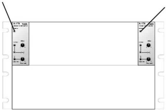
fig. 2: Recommended positioning of two A-178s
Using the gate function
The gate function in the A-178 gives you the facility to have remote switching of events in real time, simply by moving your hand towards the antenna.
The function can be used as a noise gate, using the gate signal to switch a VCA on and off, either directly or via an ADSR or slew limiter. Whenever the signal is underneath a certain voltage, the VCA simply shuts down.
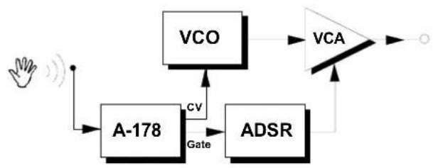
In the patch in fig. 3, just a quick movement of one hand can control both the frequency of the VCO, and a rapid repeat of the envelope controlling the VCA, and thus produce tremolo.
flowchart
graph TD
    A["Hand"] --> B["A-178"]
    B --> C["VCO"]
    C --> D["VCA"]
    D --> E["Output"]
    B --> F["Gate"]
    F --> G["ADSR"]
    G --> D
    H["Feedback"] --> B
fig. 3: User example for the gate function
An alternative to the patch in fig. 3 would be to use the ADSR to control a filter as well.
Other possible uses: Start / Stop on a sequencer, "one-shots" (ADSR-triggered noises, like thunder), switching filter characteristics, etc. (see also the user examples in the A-177 Foot Controller manual).
7. Patch-Sheet
The following diagrams of the module can help you recall your own Patches. They're designed so that a complete 19" rack of modules will fit onto an A4 sheet of paper.
Photocopy this page, and cut out the pictures of this and your other modules. You can then stick them onto another piece of paper, and create a diagram of your own system.
Make multiple copies of your composite diagram, and use them for remembering good patches and set-ups.

- Draw in patchleads with colored pens.
- Draw or write control settings in the little white circles.
8. Appendix
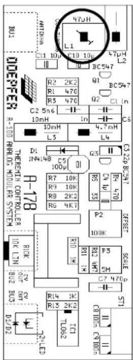
On the board a trimming inductor resp. trimming potentiometer is available with which the offset can be adjusted internally. Use it if, for instance, you connect a different antenna, and find that the front-panel control ① can't adjust the offset sufficiently to reach the null point, or if you want to reverse the standard polarity of the theremin module, and change its response so that it works on the falling edge of the internal resonant hf circuit (and thus produces a lower CV the closer your hand gets to the antenna).
Version 1:
The diagram on the right side shows the layout of the A-178's printed circuit board version 1. The trimming inductor is encircled.
Versions 2 and 3:
For the versions 2 and 3 the circuit has been modified and the inductor is replaced by a trimming potentiometer. For version 2 it is labelled "Frequency Offset"/P5 and located behind the offset front panel control. For version 3 the potentiometer is labelled P3 and located between the antenna socket and the offset front panel control (close to the capacitor labelled "C1 150p").
The different pcb versions can be distinguished by the pcb printings:
V1: no version imprint
V2: imprint "Theremin Controller Version 2 / 1998"
V3: imprint "Theremin A-178 v3"
Brand : Doepfer
Model : A-178
Category : Synthesizer