
R42 - Microphone Audix - Free user manual and instructions
Find the device manual for free R42 Audix in PDF.


| Product Type | Dual Channel Wireless Receiver (R42) |
| Brand | Audix |
| Model | R42 |
| Dimensions (W x D x H) | 406 mm x 209 mm x 44 mm (15.98 in x 8.23 in x 1.73 in) |
| Weight | 4.75 lb (2.1 kg) |
| Power Supply | 100-240 V, 50/60 Hz, 12 V DC, 1A |
| Frequency Range | A: 522-554 MHz, B: 554-586 MHz |
| Bandwidth | 32 MHz |
| Compatible Systems | Up to 8 simultaneous systems (R42) |
| Switchable Frequencies | 106 pre-coordinated frequencies |
| Frequency Response | 45 Hz – 18 kHz |
| Signal-to-Noise Ratio | 105 dB (A-weighted, 30 kHz deviation) |
| Total Harmonic Distortion | ≤0.7% (33 kHz deviation at 1 kHz) |
| Audio Output Connectors | XLR (balanced), 1/4" (unbalanced) |
| Audio Level Adjustment | -12 to +9 dB in 3 dB steps |
| Range | Up to 300 ft (91 m) |
| Transmitter Types | H60 Handheld and B60 Bodypack |
| Transmitter RF Power | 10 mW or 30 mW (selectable) |
| Battery Life (transmitters) | Approximately 14 hours (2 AA batteries) |
| Safety Instructions | Unplug when not in use; keep away from water, moisture, heat; use only provided power supply; clean with dry cloth |
| Spare Parts / Accessories | Interchangeable capsules, antennas, rackmount kits (RMT 42, RMT 42 Kit) |
Frequently Asked Questions - R42 Audix
User questions about R42 Audix
0 question about this device. Answer the ones you know or ask your own.
Ask a new question about this device
Download the instructions for your Microphone in PDF format for free! Find your manual R42 - Audix and take your electronic device back in hand. On this page are published all the documents necessary for the use of your device. R42 by Audix.
USER MANUAL R42 Audix
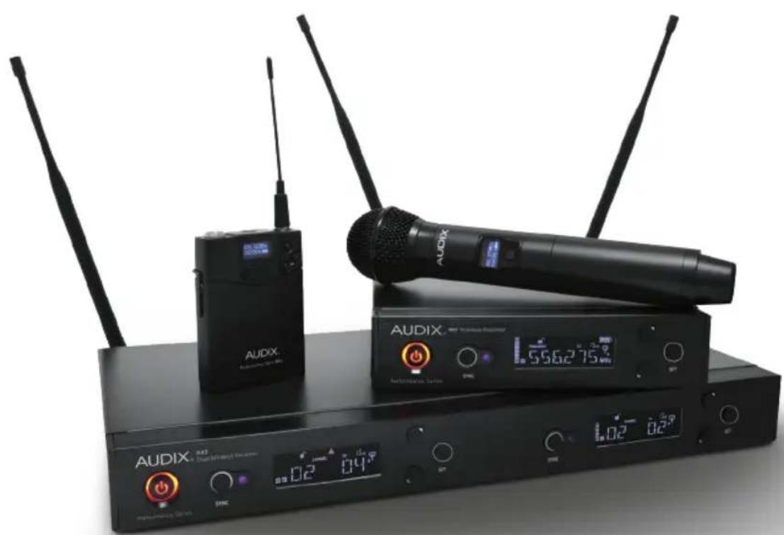
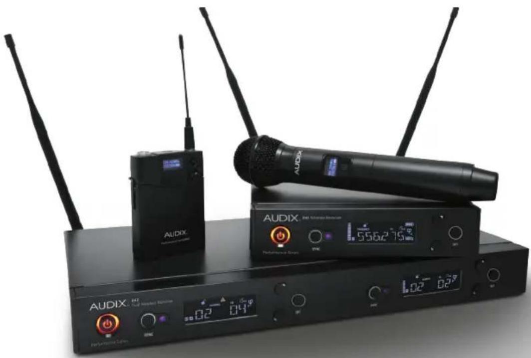
PERFORMANCE SERIES WIRELESS
AP41 & AP42 USER GUIDE
AUDIX.
TABLE OF CONTENTS
Safety Instructions & Certifications 4
Introduction 5
Quick Set Up Guide 6
R41 and R42 Receiver Front Panel 10
R41 and R42 Receiver Back Panel 11
R41 LCD Display 12
H60 Handheld Transmitter 13
B60 Bodypack Transmitter 15
Receiver Operating Instructions / Menu Functions 16
Using the H60 Handheld Transmitter 19
Using the B60 Bodypack Transmitter 21
Performance Tips 23
Rackmounts 24
Rackmount Installation 25
Troubleshooting 27
Specifications 28
Group/Channel Charts 30
International Group/Channel Charts 31
SAFETY INSTRUCTIONS
Please read this instruction manual to ensure proper use and care of your system.
Quick Safety Tips
Unplug the receiver from the wall socket when not in use
Use only with the power supply provided
Keep away from water, moisture, heat generating devices and direct sunlight
Clean only with dry cloth
Do not block the receiver from ventilation
Use only with accessories produced by Audix
Operate and store in a safe temperature range 0° C ( 32° F) - 43° C ( 110° F)
CERTIFICATIONS
This product complies with FCC Part 74 regulations and conforms to CE standards.
Documentation available upon request. Operation of wireless devices may require a license in your area. Please comply with regulations pertaining to your area. Users of wireless microphones in the USA, on frequencies listed under FCC part 74.801, must comply with eligibility and licensing requirements under FCC Part 74.834.
INTRODUCTION
Congratulations on the purchase of the Performance Series Wireless system from Audix! Your system is jam packed with features that will enable you to fine-tune the system as needed. However, the best part of our design is that the system is simple to use. For most applications, simply refer to the Quick Set Up Guide to get up and running (pgs 6-9).
Please take a few minutes and read through this manual in order to familiarize yourself with the system components and the menus. The menus are very intuitive and most questions about operating the system will be answered by understanding the structure of the menus.
QUICK SET UP GUIDE
Follow these instructions to get up and running in very little time.
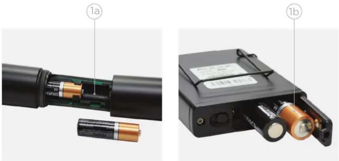
- Install 2 AA batteries in the handheld transmitter and bodypack. Refer to the diagrams on the equipment to ensure batteries are positioned correctly.
a.) Handheld transmitter: Unscrew bottom portion of the transmitter to expose battery holder. Push the first battery up through the housing with negative side up. Place the second battery below the first with negative side up. The batteries are spring loaded and will settle into place. Screw the cover back into place.
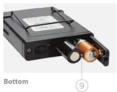
b.) Bodypack transmitter: With bodypack face down, push the spring release to the right to open. Place left battery negative side up, and the right battery negative side down. Snap the battery cover to close.
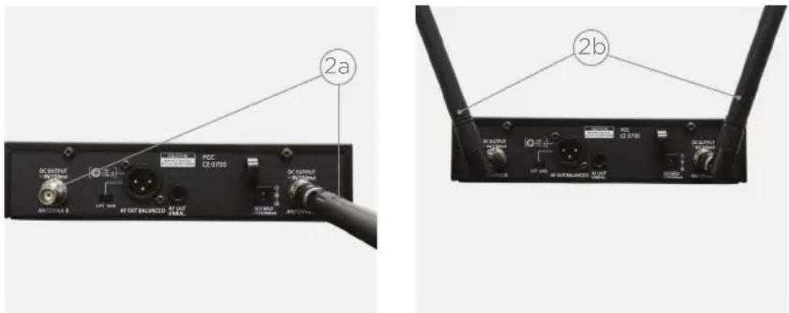
- Attach antennas to the back of the receiver. Keep each antenna straight while screwing it into the connector (2a). After attached, bend antennas into position (2b).
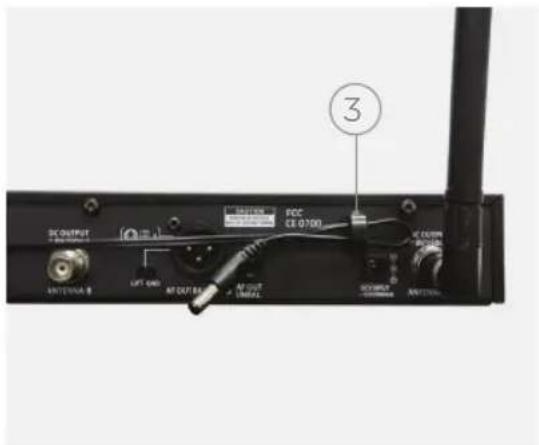
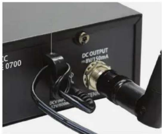
- Connect power supply. Loop cable through the metal strain relief as shown above prior to connecting power supply to receiver. Plug into power outlet.
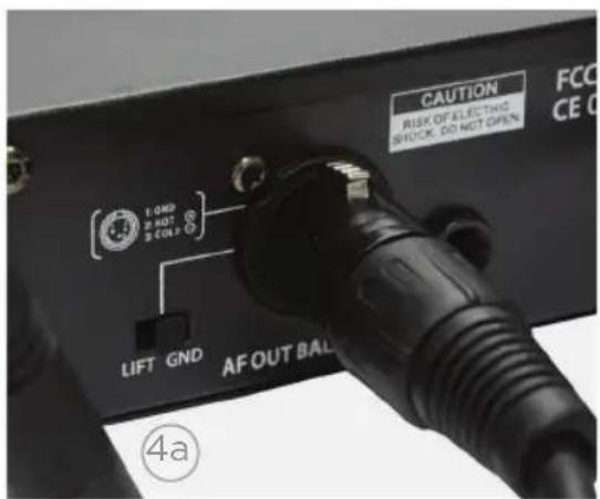
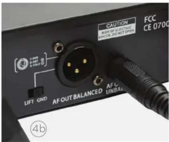
- Connect receiver to mixer or amplifier. Make sure audio levels on the mixer are muted or off. For guitar, use the 1/4" AF output (line level unbalanced, 4b). For all other applications use the XLR output (mic level, 4a).
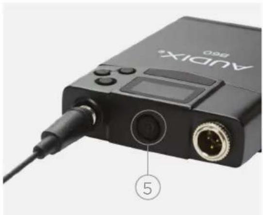
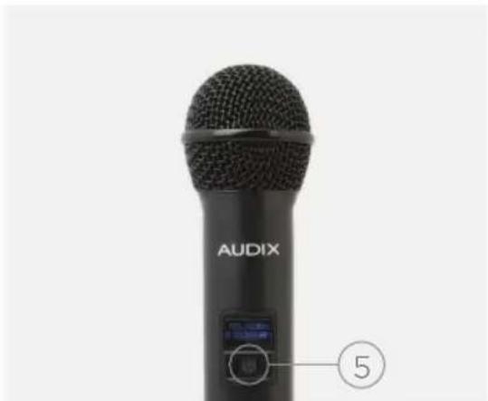
- Turn on transmitter.
QUICK SET UP GUIDE
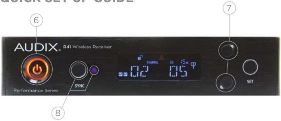
6. Turn on receiver.
- On receiver, press and hold the UP or DOWN button to trigger Scan for a clear Group/Channel. After 8-20 seconds a "Group/Channel" will appear on the receiver.
8. Sync handheld transmitter to
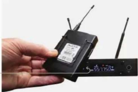
receiver. Unscrew the battery cover and locate the window housing infrared device. From a close proximity (6 inches / 152.40 mm) point the infrared window (located on the opposite side of the batteries) towards the infrared sensor next to the SYNC button on the receiver and press the SYNC button. Within a few seconds the transmitter Group/Channel and Frequency will match the receiver.
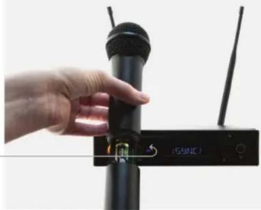
9. Sync bodypack transmitter to
receiver. Locate the window housing infrared device on the front of the bodypack. From a close proximity (6 inches / 152.40 mm) point the window below the LCD screen on the bodypack towards the infrared sensor next to the SYNC button on the receiver and press the SYNC button. Within a few seconds the transmitter Group/Channel and Frequency will match the receiver.
MULTIPLE SYSTEMS
Setting up multiple systems utilizes the Scan – Sync functions described to the left. In general, compatible channels for synchronized use are organized by Group. (See the Group/Channel chart on page 30.)
Be sure all receivers and transmitters are powered OFF.
-
Power up receiver #1 and matching transmitter: Run the standard Scan and Sync routine as described in the previous section (Quick Set Up Guide). Leave the system ON. Move the transmitter at least 6 feet (2 meters) away from the receiver.
-
Power up receiver #2 and matching transmitter: Run the Scan and the receiver will find a clear channel in the same Group as the previous system. Sync the transmitter to the receiver.
Adding more systems will follow the same procedure as above.
IMPORTANT: Be sure that all transmitters are at least 6 feet (2 meters) from each other as you set up multiple systems.
Hint: If you are using more than one frequency band, be sure to set up all systems in the same band before moving to the next.
FRONT PANEL
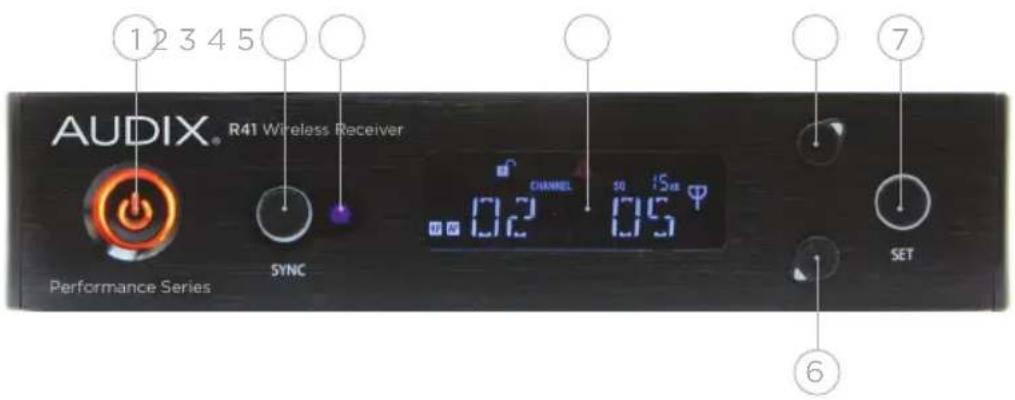
R41 SINGLE RECEIVER
R42 DUAL RECEIVER
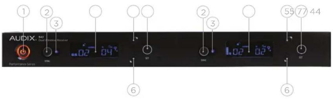
1 POWER switch. Press for instant ON. Press and hold for 3 seconds to turn system OFF.
2 SYNC button. Automatically synchronizes the transmitter to the receiver.
3 Infrared sensor. Sends data from receiver to transmitter when SYNC function is engaged.
4 High contrast LCD display. See Menu Functions on page 16 for more details.
5 UP button. Only active in Menu mode. Scrolls forward through menus. Also acts as hot key for autoscan when pushed and held.
6 DOWN button. Only active in Menu mode. Scrolls backwards through menus. Also acts as hot key for autoscan when pushed and held.
7 SET button. Press and hold to enter the Menu mode. Also used to save settings, exit the Menu mode and toggle between "Frequency" and "Group/Channel" for quick reference.
BACK PANEL
R41 SINGLE RECEIVER
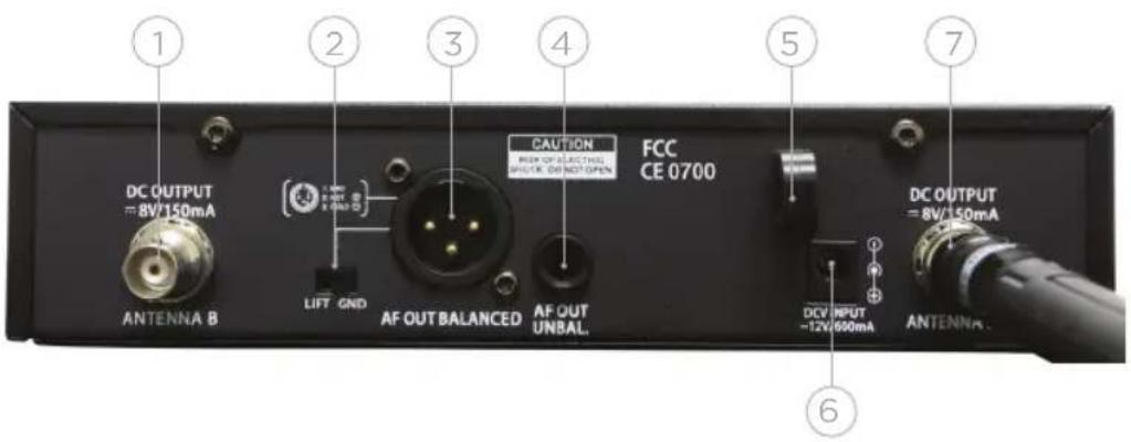
R42 DUAL RECEIVER
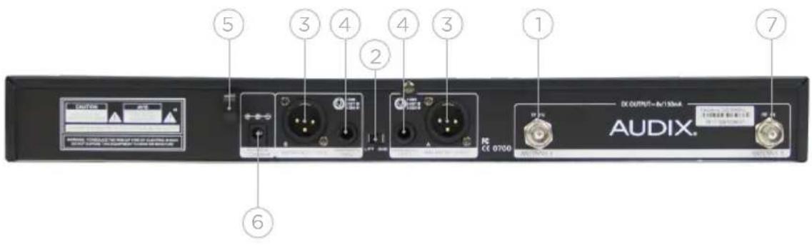
1 BNC connector for Antenna B.
2 Ground lift switch to help eliminate ground loops or noise from other sources.
3 Mic level balanced XLR output for connecting receiver to an audio mixer.
4 Unbalanced 1/4 inch output for connecting receiver to an amplifier.
5 Metal strain relief. Allows power cable to loop through for added security.
6 DC power jack for external power supply (12 V).
7 BNC connector for Antenna A.
R41 LCD DISPLAY
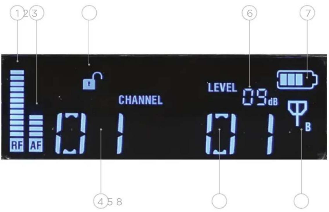
1 RF (Radio Frequency). Displays RF signal strength.
2 AF (Audio Frequency). Displays audio signal strength.
3 Indicates whether receiver is unlocked or locked for security.
4 Indicates active group when display is in Channel mode. Indicates active frequency when display is in Frequency mode.
5 Indicates active channel when display is in Channel mode. Indicates active frequency when display is in Frequency mode.
6 Displays Level (receiver gain) or Squelch (see Menu Functions, pg 14).
7 Battery level.
4 bars = Up to 14 hours
3 bars = 9 hours
2 bars = 7 hours
1 bar = 3 hours
0 bars = 1 hour
8 Active antenna indicator (A or B).
H60 TRANSMITTER - HANDHELD
The H60 is a 64 MHz wide spectrum transmitter. It covers both A and B frequency groups (pg 28).
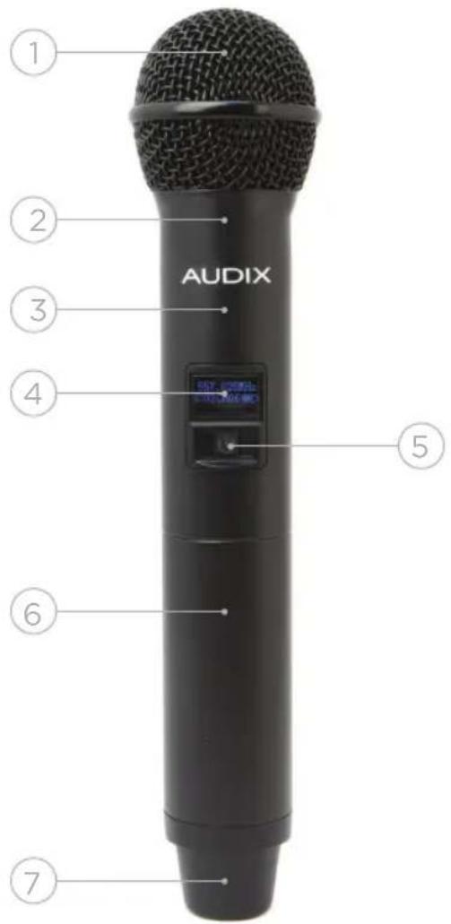
1 Grill ball. Protects capsule. Replaceable part.
2 Capsule housing. Threads on to body of the transmitter housing. Interchangeable part.
3 Transmitter housing. Contains PCB boards and electronics for RF transmission.
4 LCD display. Indicates "Group/Channel", "Frequency" and "Battery Status".
5 Power ON/OFF and MUTE button.
6 Battery cover. Must be opened to replace batteries or change transmitter power selection.
7 Transmitter antenna housing.
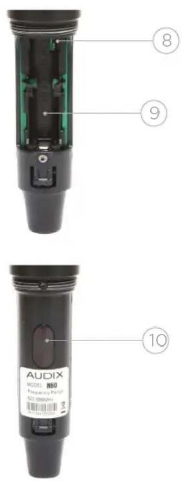
8 Power dip switch (pg 14).
9 Battery compartment.
10 Infrared sync circuit.
H60 TRANSMITTER - BATTERY COMPARTMENT
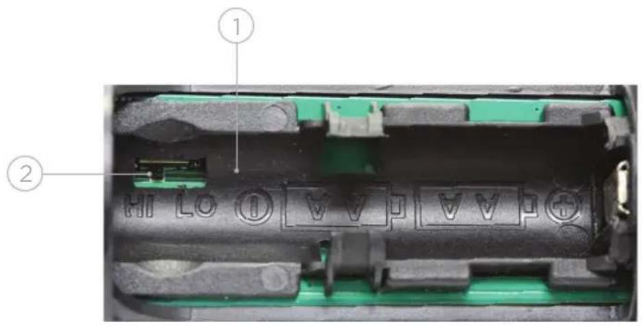
1 Houses AA batteries (see Quick Set Up Guide for installation instructions, pg 6).
2 Dip switch to choose between 30 Milliwatt (HI) and 10 Milliwatt (LO) power RF power output.
H60 TRANSMITTER - TOP
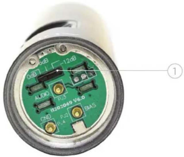
1 Dip switch with choice of 3 output gain settings for capsule (0 dB, -6 dB, -12 dB).
B60 BODYPACK - FRONT PANEL
The B60 is a 64 MHz wide spectrum transmitter. It covers both A and B frequency groups (pg 30).
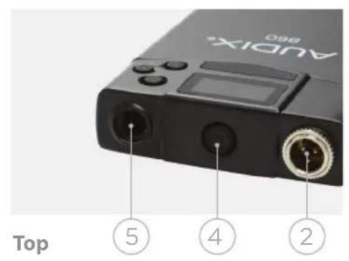
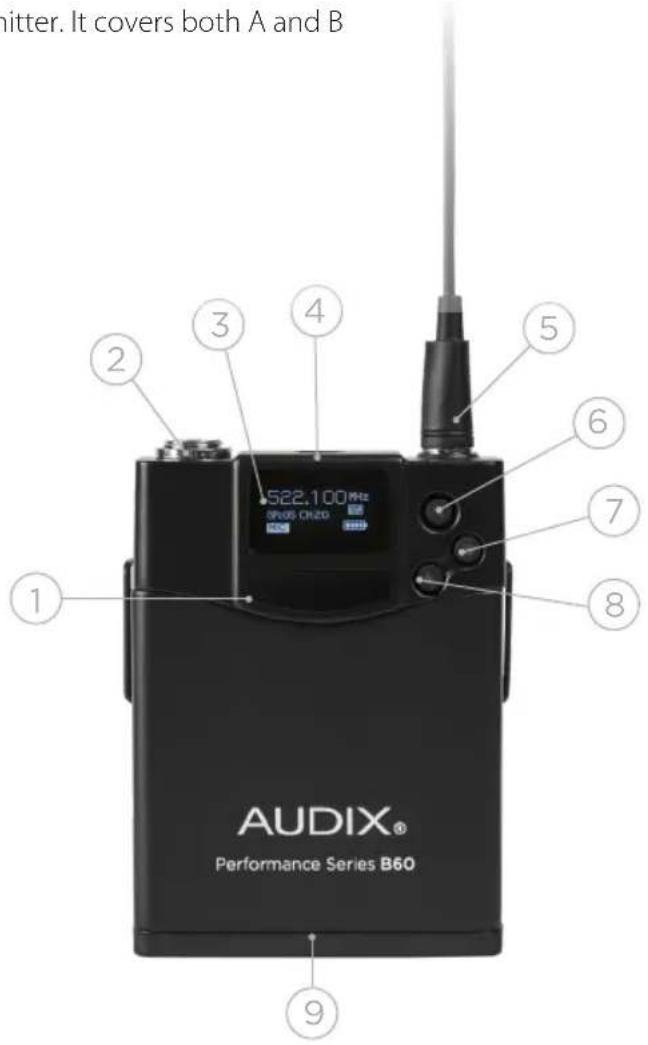
1 Infrared panel. Point towards the SYNC button on the receiver when locking the transmitter to the receiver.
2 3-pin connector for microphone cable or guitar cable.
3 LCD Display. Indicates "Group/Channel", "Frequency" and "Battery Status".
4 Power ON/OFF and MUTE button.
5 Antenna. Plug into bodypack and thread on and off. Replaceable part.
6 SET button. Use to enter Menu and Save settings.
7 UP button. Scrolls forward through menu.
8 DOWN button. Scrolls backwards through menu.
9 Battery compartment.
RECEIVER OPERATING INSTRUCTIONS
By understanding the menu structure it is easy to operate and make adjustments to the system.
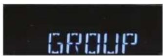
1. GROUP (1-10)
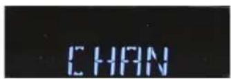
2. CHANNEL (1-7)
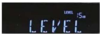
3. LEVEL (-12 to +9)
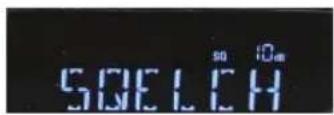
4. SQUELCH (5 - 45)
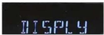
5. DISPLAY (FREQUENCY, CHANNEL, SQUELCH, LEVEL)
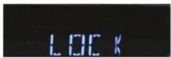
6. LOCK (ON, OFF)
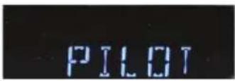
7. PILOT (ON, OFF)
8. SCAN (SCAN FOR OPEN FREQUENCY)
9. T-LOCK (ON, OFF)
Activate Menu: To activate the menu, press the SET button until "GROUP" appears on the display.
Scroll Through Menu: Each of the menu functions are displayed on the screen in the order they appear in the grid above. To scroll through the menu press the UP button. Use the DOWN button to scroll in reverse. For example, if you are on "GROUP" and want to quickly get to "T-LOCK", press the DOWN button once.
MENU FUNCTIONS
GROUP/CHANNEL
These two functions work hand-in-hand as they represent preselected frequency coordinates. See page 30 for a table of coordinated frequencies. Each time a SCAN is performed (by pressing and holding the UP or DOWN button), a clear "Group/Channel" will be chosen and appear on the display. It will be one of the 106 predesignated frequencies available in your system (see page 30). The SCAN function takes the guesswork out of finding the best available frequency and is also handy for adding more systems into the mix.
"Group/Channel" can also be controlled manually from the menu. Activate the menu (see previous page). When "GROUP" appears, press SET. The current "Group" will be displayed. Press either the UP or DOWN button to scroll to another "Group" and then press SET. The new "Group" will be saved and will appear on left side of the display.
Hint: The word "CHANNEL" will appear to the upper right of the number. This means the display is in Channel mode. The menu displays "Group/Channel" as the default. Press the SET button (quickly) and the "Frequency" will appear on the screen. After 5 seconds it will default back to "Group/Channel". To set "Frequency" as the default display see "Display" (pg 18).
To change the channel, go to "CHAN" in the menu (it's next in line after "GROUP") and press SET. The current channel will be displayed. Scroll through the channels and select the one you want, then press SET. The same applies if "Frequency" has been selected as the default.
GROUP/CHANNEL (AP42 ONLY)
Please note that the AP42 dual receiver system is designed for both receivers to be used in the same Group. Whenever the Scan-Sync function is run, the AP42 system will choose the optimum Group and place both receivers in the same Group. We suggest always using the Scan-Sync function to choose new frequencies. When manually changing the Group, please note that the Group will change accordingly on both receivers.
FOR BEST RESULTS, DO NOT CHANGE FREQUENCIES DURING A PERFORMANCE.
LEVEL
This setting allows for additional gain control over the receiver. The factory setting is +6, a good gain setting for Audix dynamic microphones. The VX5 condenser microphone has much more output than a dynamic mic and is better suited in the -6 or -9 range.
Hint: The key to a good sound with the least amount of noise and distortion is finding the balance between the mixer, the receiver and the capsule gain. A soft singer, for example, will require more gain on the mixer and receiver, which could potentially add some noise into the system. Fine tuning the receiver setting can be helpful in these cases. A loud singer, on the other hand, will require less gain and possibly a gain reduction on the transmitter itself for control over distortion.
SQUELCH
"Squelch" is an important design facet of a wireless circuit. It mutes or suppresses noise from the receiver in the absence of a desired signal. Typically, the lower the squelch, the less signal it takes to activate the receiver. The higher or tighter the squelch, the higher
the signal required. Squelch also affects operating distance. Unless you run into extreme conditions where you need more or less operating range than normal, we recommend keeping the squelch around the factory setting of +15.
DISPLAY
There are two default options for the LCD screen: "FREQUENCY" or "CHAN". Additionally, you have a choice of displaying either "SQ" (squelch) or "LEVEL" settings. Activate the menu screen and scroll to "DISPLY". Press SET and "FREQUENCY" will flash. Press the UP button and "CHANNEL" will flash. Press the UP button and "SQ" (squelch) will flash. Press the UP button and "LEVEL" will flash.
Once you decide whether you want "Frequency" or "Channel" as the default, press SET to save it. If you choose "Frequency", the receiver frequency will be displayed as the default. If you choose "Channel", then "Group/Channel" will be displayed as the default.
Hint: If "Frequency" is selected as the default, then by pressing the SET button quickly, the "Group/Channel" info will be displayed for a few seconds. If "Channel" is selected as the default, then by pressing the SET button quickly, the "Frequency" will be displayed for a few seconds.
The option of showing either "Level" or "Squelch" is also available. Whatever settings are chosen for those items will be displayed once selected and saved. "Level" is the factory default.
LOCK
You can lock the receiver to prevent someone from accidentally pressing SCAN, SYNC or the POWER button. Once everything is set and working, this is recommended.
Locking Feature For AP42
In order to insure that someone does not change a Group unintentionally, there is a Lock feature added to the AP42. Scroll through the menu to the "LOCK" screen and choose lock "ON." This will disable the SCAN, SYNC, SET, UP, and DOWN buttons. To unlock the receiver, scroll through the menu to the "LOCK" screen and choose lock "OFF". All functions will be enabled.
PILOT
This is an inaudible tone generated by the transmitter to the receiver as additional insurance to keep the receiver from generating noise when there is no signal present. The Pilot should be left ON and only be turned OFF temporarily if troubleshooting the system for problems.
SCAN
The option to perform a scan for a clear channel. The Audix Performance Series Wireless Scan feature performs a scan to find clear and open frequencies as well as compatible frequencies when using multiple systems.
T-LOCK
Transmitter lock. This function disables the POWER and MUTE button on the handheld transmitter. This helps prevent the transmitter from accidentally being MUTED or turned OFF during a performance.
Hint: The bodypack has this feature built into the menu.
IMPORTANT
After making a change to one of the menu settings above, it is important to RE-SYNC the microphone to the receiver in order to clear the previously saved information.
USING THE H60 HANDHELD TRANSMITTER
POWER ON/ MUTE
The button below the display powers ON the transmitter. To power OFF the transmitter, press and hold the button for 2 seconds. A quick touch of the POWER button will MUTE the transmitter. Another quick touch will restore signal. This is a noiseless function and is very convenient for applications where a vocalist or presenter wants complete control of the microphone.
LCD DISPLAY
The display indicates the frequency of the transmitter along with "Group/Channel". In order for the microphone to work, the frequency of the microphone must match that of the receiver. If they do not match, go into the Sync mode (see Quick Set Up Guide, pg 6).
The same rules of acoustics that apply to a wired microphone also apply to the handheld transmitter.
OM SERIES
The OM Series capsules are designed to maximize gain before feedback on stage. The hypercardioid pickup pattern of the microphones are designed to reject sound from instruments on stage. For best results, sing within a few inches of the microphone.
SETTING OUTPUT LEVEL
Choice of 10 Milliwatt or 30 Milliwatt RF transmission levels (pg 14).
VX5
The VX5 condenser microphone has a more open supercardioid pickup pattern. The extended on-axis reach is ideal for singer/songwriters, keyboard players and vocalists who want more freedom to work the microphone from a distance.
INTERCHANGEABLE CAPSULES
It is very easy to change a capsule assembly. Simply unscrew the capsule assembly at the ring above the Audix logo.
Hint: Do not unscrew the grill ball as it is a separate threaded piece intended to be removed separately from the capsule housing.
CONTROLLING DISTORTION
Audix capsules are designed to handle very high sound pressure levels without distortion. If distortion is detected, try to minimize or eliminate it from the mixing console by turning down the trim and gain controls. If distortion persists, there is a gain setting at the capsule. First remove the capsule assembly. Locate the dip switch on the green PCB inside the housing. Use a miniature screwdriver to move the switch from 0 dB to -6 or -12.
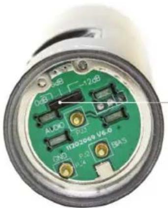
DIP SWITCH FOR GAIN CONTROL
Hint: Padding the sensitivity of the capsule at the source is the most effective way to control distortion without changing the natural sound quality or response of the microphone.
USING THE B60 BODYPACK TRANSMITTER
There are three buttons that control the menu functions—SET, UP (forward) and DOWN (backwards). The functions controlled by the buttons are RF OUTPUT, LEVEL and LOCK.
There are 3 menu functions: RF POWER OUTPUT, LEVEL, LOCK.
RF POWER OUTPUT
This controls the level of the RF output. LO = 10 Milliwatts or HIGH = 30 Milliwatts.
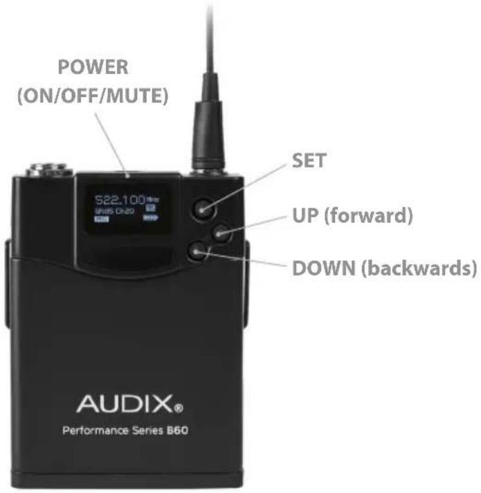
TO SET RF POWER OUTPUT
Make sure the bodypack is turned ON. Press and hold the SET button. Press the UP button until "RF AMP" or "RF OUTPUT" appears on the display. Press the SET button and the display will flash, indicating the current setting, either "HIGH" or "LO" or "10mW" or "30mW", depending on which bodypack model version you have. Press the UP button to toggle between HIGH = 30 milliwatt or LO = 10 milliwatt. Press SET to save the setting.
Hint: The Lo gain setting is helpful on a smaller stage with direct line of sight or in areas with a lot of wireless congestion. It also improves battery life.
GAIN CONTROLS
There are two level settings: Line Level and Mic Level. Mic level features three relative gain settings: 0, -6, -12. Line level features -24 dB for active guitar or bass pickups.
TO SET LEVEL
Press and hold the SET button until "LEVEL" appears on the display. Press the SET button once and Mic Level (gain) or Line Level will flash. Use the UP button or DOWN button to select either Mic or Line Level. Press the SET button again. Use the UP button or DOWN button to select the gain level desired. Press SET and the current setting will appear. Use the UP or DOWN button to scroll through the settings. Press SET to save the one you want.
LOCK
This disables the POWER button from being active. This prevents the bodypack from being accidentally turned off or muted. RF Output and LEVEL are locked when the B60 is locked.
TO SET LOCK
Press and hold the SET button and use the UP or DOWN buttons until "LOCK" appears on the display. Press the SET button and the current setting will flash "ON" or "OFF". Use the UP or DOWN button to scroll through the two options. Press SET to save the setting.
THERE ARE THREE USES FOR THE BODYPACK TRANSMITTER:
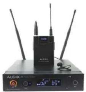
- Lavalier microphones (ADX10, L5)
(HT2, HT5, HT7)
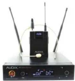
- Headworn microphones
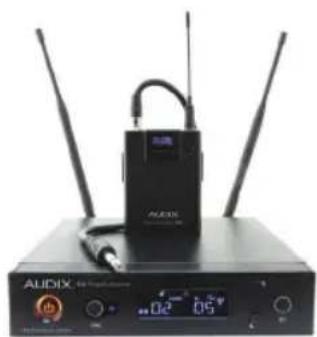
- Sax, brass, flute and guitar
CONNECTOR
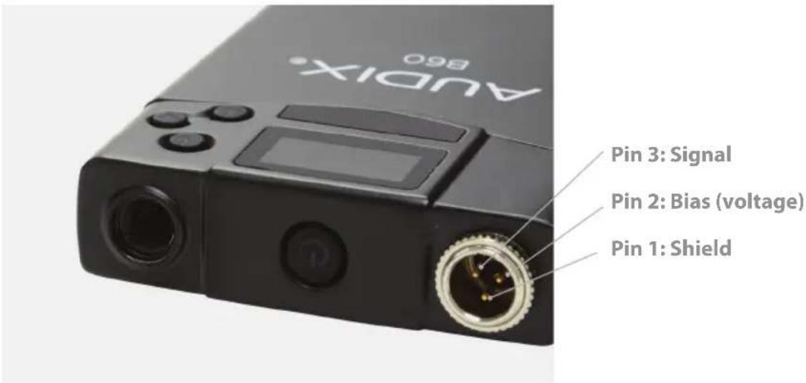
The bodypack uses a mini 3-pin XLR connector for all microphones. Other brands of microphones can be used with the Audix Performance Series Wireless system; however, it will be necessary to rewire the microphone connector to a mini 3-pin XLR (f). In this case, note the following pin configuration:
PERFORMANCE TIPS
The best position for a wireless receiver is within line of sight whenever possible. For more complex set ups, consider extending the antenna range by using the ANTDA4161 active antennas.
High quality batteries will provide the best results for handheld and bodypack transmitters. Rechargeable batteries typically have a shorter usage span. It is not possible to use two sets of transmitters simultaneously on the same frequency. It will not work. Each time a scan and sync is performed, the transmitter will always be tuned to the current frequency on the receiver. When using dual systems, always scan and sync each channel independently from one another.
SETTING UP MULTIPLE SYSTEMS
It is fairly straightforward to get 16 channels of wireless to work simultaneously within one frequency band (32 megs). This is done using a standard Scan and Sync method. The systems will stay in the same Group until the group maxes out its channel selection. At this point, it may be necessary to manually select a different Group for additional pre-coordinated channels.
Both antennas must be installed in order for the diversity function to work properly. Always attach both antennas to the receiver.
RACKMOUNTS
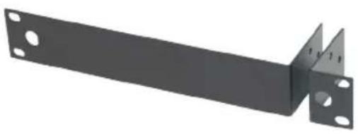
RMT 4161
Optional accessory. Adapts one R41 or R61 receiver into a single 19 inch rack space.
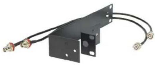
RMT 41 Kit
Optional accessory. Includes RMT 4161 and BNC cables for front mounting antennas.
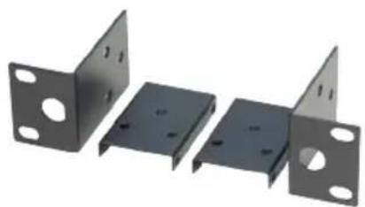
RMT 241
Optional accessory. Adapts two R41 or R61 receivers into a single 19 inch rack space. Note: Antennas must remain rear mounted when using this rackmount.
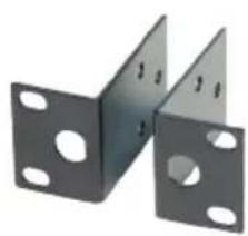
RMT 42
Optional accessory. Adapts one R42 or R62 two channel receiver into a single 19 inch rack space.
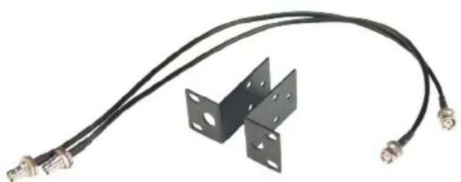
RMT 42 Kit
Included accessory with AP42 and AP62 systems. Includes RMT42 rackmount and BNC cables for front mounting antennas.
RACKMOUNT INSTALLATION
RMT 4161
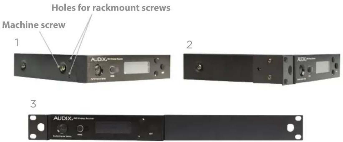
1 The holes for attaching rackmounts are located on the sides of the receiver.
2 The rackmounts are attached with two Phillips head screws and are intended to lay over the Torx machine screw that holds the receiver enclosure together. For additional support, the Torx screw may be removed and used as one of the fastening screws for the rackmount.
3 After both metal pieces are fastened to the receiver, it is ready to be mounted into the rack.
RMT 41 KIT
3
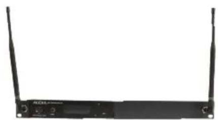
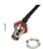
1 This kit includes the BNC cables needed for front mounting the antennas. Remove the hex nut from the threaded end of the BNC connector.
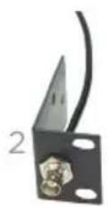
2 Note: The rackmount has a hole that is slotted on one side. The flat portion of the BNC connector must line up with the slotted portion of the hole in order to be pushed through. It can only go in one way. Once it is through the hole, screw the nut back into place and tighten.
3 After both sides are secure, connect the cables to Antenna A and Antenna B on the back of the receiver. The antennas may now be front mounted to the BNC connectors.
RMT 241
1

2
3

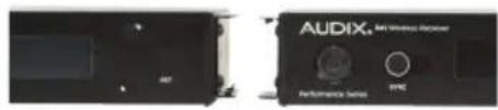
1 Using the larger Phillips head screw, fasten the metal rackmount ears to the outside of each receiver. Fasten the flat connecting metal piece to the inside of each receiver.
2 Place the two receivers together and line up the holes in order to adjoin the two pieces. Once lined up, use the small screws to fasten the top side together. Then turn the receivers over and fasten the bottom side.
3 Tighten up all screws and the receivers are now ready to be mounted into the rack.
RMT 42

Attach the metal rack ears in the normal fashion to each side of the receiver. See figure #2 under RMT 4161 on previous page.
RMT 42 KIT
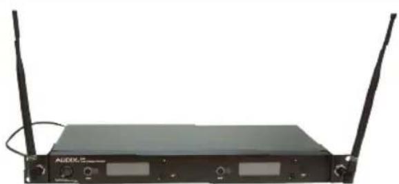
After the RMT 42 is attached to the receiver, follow the instructions for RMT 4161 on previous page for attaching BNC connectors and front mounting the antennas.
TROUBLESHOOTING
| PROBLEM POSSIBLE CAUSE CORRECTIVE ACTION | ||
| Receiver won't power up | Bad connection | Check your power cord to make sure it's plugged into the outlet and receiver correctly |
| Transmitter will not power up | Batteries | Make sure they are installed correctly (pg 6) or check the battery life indicator on the transmitter |
| Lock mode may be ON | If T-Lock is ON, change to OFF (pg 19) | |
| Transmitter locked up | Software conflict | Re-load batteries in order to clear memory |
| No RF signal | Transmitter is not synced to receiver | Sync transmitter to receiver (pg 8) |
| Receiver is out of range Reduce the distance | ||
| RF signal is weak | Antennas may not be connected correctly | Adjust antennas or use remote antennas |
| Possible frequency interference from another wireless device | Re-Scan and Sync to another frequency (pg 8) or try a lower power setting if on a smaller stage or venue (pgs 14, 21) | |
| No AF | Transmitter muted | Check transmitter ON/OFF button |
| Transmitter battery low or dead | Replace battery | |
| Receiver not hooked up properly | Check cable connections on both receiver and console, also check cable for continuity with a cable tester | |
| AF Signal distorted | Transmitter sensitivity setting is too high | Reduce output level on transmitter (pgs 14, 21) or reposition vocal or instrument microphone |
| Receiver level too high | Change gain level of receiver (pg 17) | |
SPECIFICATIONS
| R41/R42 Receiver | |
| Frequency Range A: 522 MHz - 554 MHz / B: 554 MHz - 586 MHz | |
| Bandwidth 32 MHz | |
| Compatible Systems Up to 16 systems (R41) / 8 systems (R42) simultaneous use | |
| Switchable Frequencies 106 Pre-coordinated frequencies | |
| Manual Mode n/a | |
| Frequency Response 45 Hz – 18 kHz | |
| Compander System 2:1 | |
| Pilot Tone 32 kHz | |
| Receiving System Single tuner, antenna diversity | |
| Signal-to-Noise Ratio 105 dB at 30 kHz deviation (A-weighted) | |
| Total Harmonic Distortion ≤0.7% (33 kHz deviation at 1 kHz) | |
| Sensitivity 5 dBμV (S/N 60 dB at 25 kHz deviation, A-weighted) | |
| Audio Output (Level=6) | Balanced: -12 dbv @ 25 kHz deviation, 600 ohm load1/4": -18 dbv @ 25 kHz deviation, 10 ohm load |
| Output Connectors 1/4", XLR | |
| Audio Level Adjustment | -12 to +9 in 3 db steps |
| Range | 300', (91 m) |
| Power Supply | 100 - 240 V / 50 - 60 Hz, 12 V DC, 1A |
| Dimensions (W / D / H) | 205 mm / 8.07 in x 206 mm / 8.11 in x 44 mm / 1.73 in (R41)406 mm / 15.98 in x 209 mm / 8.23 in x 44 mm / 1.73 in (R42) |
| Net Weight | 1.92 lb / 0.87 kg (R41)4.75 lb / 2.1 kg (R42)H60 Handheld Transmitter |
| RF Power Output | 10 mW, 30 mW |
| Frequency Bandwidth | 64 MHz |
| Gain Controls | 0 dB, -6 dB, -12 dB |
| Input Connector | n/a |
| Batteries Included | 2 AA 1.5 V |
| Current Consumption | 110 mA typical |
| Battery Life | Approximately 14 hours (depending on battery type and usage) |
| Input Impedance | n/a |
| Max Sound Pressure Level | >140 dB (depending on capsule) |
| Dimensions | 2.1in diameter body, 10.43" (L), 53 mm diameter body, 265 mm (L) |
| Net Weight | 11.0 oz / 312 g (without battery) |
| B60 Bodypack Transmitter | |
| RF Power Output | 10 mW, 30 mW |
| Frequency Bandwidth | 64 MHz |
| Gain Controls | 0 db, -6 dB, -12 dB, -24dB |
| Input Connector | 3 pin mini-XLR |
| Batteries Included | 2 AA 1.5 V |
| Current Consumption | 110 mA typical |
| Battery Life | Approximately 14 hours (depending on battery type and usage) |
| Input Impedance | Mic: 10k ohm, Line: 1M ohm |
| Max Sound Pressure Level | Approx. 128 db - 140 dB (depending on microphone) |
| Dimensions (W / L / D) | 67 mm / 2.6 in x 90 mm / 3.5 in x 17 mm / 0.67 in |
| Net Weight | 3.0 oz / 85 g (without batteries) |
R41A GROUP/CHANNEL CHART (522 - 554)
GROUP
CHANNEL
| 1 2 3 4 | 5 6 7 8 9 10 | |||||||||
| 1 5 | 45.625 541. | 475 547.475 | 554.125 553.300 553.6 | 25 553.600 | 553.450 550.500 551.7 | 25 | ||||
| 2 5 | 44.500 541.075 | 547.075 | 549.675 551.625 547.3 | 50 552.975 | 549.700 547.875 550.5 | 00 | ||||
| 3 5 | 43.575 540.450 | 546.450 | 548.650 544.925 543.4 | 75 552.150 | 548.775 546.425 549.5 | 75 | ||||
| 4 5 | 42.350 539.625 | 542.850 | 548.125 541.600 542.4 | 00 551.750 | 547.325 545.500 548.1 | 25 | ||||
| 5 5 | 35.075 538.500 | 535.475 | 529.475 540.450 538.3 | 50 551.025 | 544.700 541.750 545.5 | 00 | ||||
| 6 5 | 33.625 537.575 | 534.450 | 529.075 527.325 535.5 | 00 527.625 | 543.475 538.925 544.2 | 75 | ||||
| 7 5 | 31.575 536.850 | 532.500 | 528.450 526.075 533.9 | 50 526.500 | 534.625 537.475 535.4 | 25 | ||||
| 8 5 | 30.850 536.850 | 530.350 | 524.850 525.525 528.0 | 75 525.575 | 532.750 534.150 533.5 | 50 | ||||
| 9 5 | 24.350 524.525 | 526.375 | 523.475 530.675 532.6 | 00 531.475 | ||||||
| 10 5 | 22.100 525.800 | 523.075 | 530.250 530.500 531.0 | 50 | ||||||
| 11 5 | 22.450 525.150 | 528.100 | 525.950 | |||||||
| 12 5 | 22.350 523.750 | 523.150 | ||||||||
| 13 5 | 22.525 |
R41B GROUP/CHANNEL CHART (554 - 586)
GROUP
CHANNEL
| 1 2 3 4 | 5 6 7 8 9 10 | |||||||||
| 1 5 | 83.475 585. | 575 584.500 | 584.675 584.400 | 584.825 | 583.350 | 584.675 585.375 | 584.400 | |||
| 2 5 | 83.075 584. | 850 578.125 | 582.600 582.350 | 579.125 | 581.600 | 582.600 584.500 | 582.350 | |||
| 3 5 | 82.450 559. | 600 571.450 | 579.400 581.475 | 578.625 | 573.825 | 581.750 581.150 | 581.475 | |||
| 4 5 | 81.625 558. | 975 565.600 | 571.600 579.125 | 574.475 | 572.800 | 579.400 580.600 | 579.125 | |||
| 5 5 | 80.500 557. | 750 564.975 | 570.975 577.600 | 567.550 | 571.550 | 578.375 579.200 | 578.100 | |||
| 6 5 | 79.575 557. | 025 564.150 | 570.150 576.975 | 566.000 | 570.775 | 577.150 578.125 | 577.100 | |||
| 7 5 | 78.350 555. | 675 563.025 | 569.750 576.150 | 561.100 | 569.050 | 576.650 577.450 | 576.375 | |||
| 8 5 | 54.650 561. | 675 569.025 | 575.025 557.075 | 565.700 | 575.300 | 576.100 575.850 | ||||
| 9 5 | 60.125 567. | 675 573.675 | 555.300 561.075 | 574.450 | 575.250 | 574.825 | ||||
| 10 5 | 66.125 572. | 125 | 571 | 450 572.250 | 573.475 | |||||
| 11 5 | 64.700 565. | 500 572.850 | ||||||||
| 12 5 | 62.600 563. | 400 570.050 | ||||||||
| 13 5 | 61.050 561. | 850 564.525 | ||||||||
| 14 5 | 56.275 557. | 075 562.450 | ||||||||
| 15 | 554.250 560.575 | |||||||||
INTERNATIONAL E FREQUENCY GROUP/CHANNEL CHART
Audix offers wireless systems that work with the international free frequency (823 - 832 MHz and 863 - 865 MHz).
GROUP
CHANNEL
| 1 2 3 4 | 5 6 7 8 9 10 | |||||||||
| 1 8 | 23.625 823.825 823.175 | 827.450 823.500 823.250 824.025 | 824.975 823.000 823.975 | |||||||
| 2 8 | 28.275 825.000 827.200 | 828.575 824.500 823.750 826.225 | 826.025 824.225 825.775 | |||||||
| 3 8 | 29.100 825.575 827.825 | 829.250 825.750 825.250 826.975 | 828.000 824.975 828.625 | |||||||
| 4 8 | 30.225 826.550 829.375 | 830.275 827.250 826.500 829.300 | 828.700 828.000 829.500 | |||||||
| 5 8 | 30.625 827.075 829.875 | 830.700 828.250 827.500 829.700 | 829.100 829.100 831.900 | |||||||
| 6 8 | 31.625 829.700 830.625 | 831.725 863.150 828.250 863.125 | 863.150 829.500 863.475 | |||||||
| 7 8 | 33.400 831.500 863.625 | 863.625 863.550 863.125 863.525 | 863.550 863.125 863.900 | |||||||
| 8 8 | 33.825 863.350 864.350 | 864.325 864.600 863.525 864.175 | 864.175 863.525 864.550 | |||||||
| 9 8 | 34.625 863.900 864.875 | 864.175 864.625 864.600 864.175 | ||||||||
| 10 8 | 34.875 864.625 864.625 |
AUDIX®
www.audixusa.com
503.682.6933
©2018 Audix Corporation All Rights Reserved.
Audix and the Audix Logo are trademarks of
Audix Corporation.
- PERFORMANCE SERIES WIRELESS
- TABLE OF CONTENTS
- SAFETY INSTRUCTIONS
- QUICK SAFETY TIPS
- CERTIFICATIONS
- INTRODUCTION
- QUICK SET UP GUIDE
- TURN ON RECEIVER
- SYNC HANDHELD TRANSMITTER TO
- SYNC BODYPACK TRANSMITTER TO
- MULTIPLE SYSTEMS
- FRONT PANEL
- BACK PANEL
- R41 LCD DISPLAY
- H60 TRANSMITTER - HANDHELD
- H60 TRANSMITTER - BATTERY COMPARTMENT
- H60 TRANSMITTER - TOP
- B60 BODYPACK - FRONT PANEL
- RECEIVER OPERATING INSTRUCTIONS
- MENU FUNCTIONS
- GROUP/CHANNEL
- GROUP/CHANNEL (AP42 ONLY)
- FOR BEST RESULTS, DO NOT CHANGE FREQUENCIES DURING A PERFORMANCE
- LEVEL
- SQUELCH
- DISPLAY
- LOCK
- LOCKING FEATURE FOR AP42
- PILOT
- SCAN
- T-LOCK
- IMPORTANT
- USING THE H60 HANDHELD TRANSMITTER
- POWER ON/ MUTE
- LCD DISPLAY
- OM SERIES
- SETTING OUTPUT LEVEL
- VX5
- INTERCHANGEABLE CAPSULES
- CONTROLLING DISTORTION
- USING THE B60 BODYPACK TRANSMITTER
- RF POWER OUTPUT
- TO SET RF POWER OUTPUT
- GAIN CONTROLS
- TO SET LEVEL
- TO SET LOCK
- THERE ARE THREE USES FOR THE BODYPACK TRANSMITTER
- CONNECTOR
- PERFORMANCE TIPS
- SETTING UP MULTIPLE SYSTEMS
- RACKMOUNTS
- RMT 4161
- RMT 41 KIT
- RMT 241
- RMT 42
- RMT 42 KIT
- RACKMOUNT INSTALLATION
- TROUBLESHOOTING
- SPECIFICATIONS
- R41A GROUP/CHANNEL CHART (522 - 554)
- R41B GROUP/CHANNEL CHART (554 - 586)
- INTERNATIONAL E FREQUENCY GROUP/CHANNEL CHART
- AUDIX®
Brand : Audix
Model : R42
Category : Microphone