
Lightbridge - Wi-Fi repeater DJI - Free user manual and instructions
Find the device manual for free Lightbridge DJI in PDF.


| Product Type | Wi-Fi Repeater / HD Video Transmission System |
| Brand | DJI |
| Model | Lightbridge |
| Air System Dimensions (no antennas) | 68 mm (L) x 48 mm (W) x 21 mm (H) |
| Ground System Dimensions (no antennas) | 125 mm (L) x 90 mm (W) x 20 mm (H) |
| Air System Weight (no antennas) | 71 g |
| Ground System Weight (no antennas) | 295 g |
| Operating Voltage (Air System) | 3S~6S (11.1V~22.2V) |
| Operating Voltage (Ground System) | 3S~6S (11.1V~22.2V) or 11V~26V via power adapter |
| Transmission Distance (outdoors, unobstructed) | 1.7 km |
| Working Frequency | 2.4 GHz ISM |
| Video Input (Air System) | HDMI (up to 1920x1080@60fps) or AV (PAL/NTSC) |
| Video Output (Ground System) | HDMI (up to 1080i60) or USB (to smart device via app) |
| Antenna Gain (Air System) | 2.0 ± 0.7 dBi @ 2450 MHz |
| Antenna Gain (Ground System) | 5.0 ± 0.7 dBi @ 2450 MHz |
| Operating Temperature | -10°C to 50°C |
| Supported Remote Controls | Futaba, JR, Spektrum, Devention (PPM output) |
| Master-Slave Mode | Supports one master (control + video) and multiple slaves (video only) |
| Firmware Upgrade | Via DJI LIGHTBRIDGE Assistant (Windows) |
Frequently Asked Questions - Lightbridge DJI
User questions about Lightbridge DJI
0 question about this device. Answer the ones you know or ask your own.
Ask a new question about this device
Download the instructions for your Wi-Fi repeater in PDF format for free! Find your manual Lightbridge - DJI and take your electronic device back in hand. On this page are published all the documents necessary for the use of your device. Lightbridge by DJI.
USER MANUAL Lightbridge DJI
Thank you for purchasing the DJI LIGHTBRIDGE. Please visit the DJI LIGHTBRIDGE page on www.dji.com regularly to keep up with product information, technical updates and manual corrections. Information in this manual is subject to change without notice in line with product upgrades and updates.
Users must comply with local radio transmission laws and regulations when using this product. In using this product, you hereby agree to this disclaimer and signify that you have understood all points completely. When assembling this product, follow all instructions carefully. The manufacturer and seller assume no liability for any damage or injury arising from the use of this product.
DJI is a registered trademark of DJI. Names of product, brand, etc., appearing in this manual are trademarks or registered trademarks of their respective owner companies. This product and manual are copyrighted by DJI with all rights reserved. No part of this product or manual shall be reproduced in any form without the prior written consent or authorization of DJI.
Profile
A complete DJI LIGHTBIRDGE comprises of an air system and a ground system. It is a high definition video transmitter, flight controller On Screen Display (OSD) and supports remote controls using the 2.4GHz frequency band. As it is small, power efficient and highly sensitive, the DJI LIGHTBRIDGE can be used for many activities. The air system must be attached to the aircraft and the ground system must be connected to a monitor to display the video and flight controller OSD information.
When the DJI LIGHTBRIDGE transmits the video and flight controller OSD information, the air system is the transmitter while the ground is the receiver. The air system pulls video from the camera and OSD information from the flight controller then modulates it and transmits to the ground system. The ground system then receives the information, demodulates it and sends it to a monitor or mobile device. The DJI LIGHTBRIDGE App, available for smart devices is required for an ideal viewing experience.
When the DJI LIGHTBRIDGE transmits the remote control signal the ground system works as a transmitter while the air system works as a receiver. The ground system can connect to two remote controls, one for aircraft and the other for gimbal control. A DJI flight control system with DBUS port is required as the built in receiver only supports the DJI DBUS protocol.
* 2.4GHz remote controls must be connected correctly to the ground system. Incorrect connection may lead to malfunction due to interference.
Caution
Aircraft in flight can cause serious damage or injury. Please fly safely at all times.
Assembly Cautions
(1) Install antennas before powering on ground system or air system.
(2) Point air system antennas downward when in use, do not twist or bend antennas. Avoid obstructing antennas to ensure transmission quality.
(3) Keep both ends of air system antennas as further as possible to achieve optimal transmission performance. In addition, keep these antennas away from metals.
(4) Use only DJI approved antennas and installed them correctly. Other antennas are incompatible.
(5) Only 2.4GHz remote control can be connected to ground system of DJI LIGHTBRIDGE. Chose the remote control with PPM trainer output.
(6) 2.4GHz remote controls must be connected to ground system for aircraft and gimbal control through training ports. RF functions must be switched off.
(7) Do not create shorts or open circuits when soldering.
(8) Do not rotate gimbal if connected to camera HDMI port using DJI AV gimbal. This will cause gimbal or HDMI cable damage.
(9) Disconnect HDMI cable from the camera when powering on the DJI non-HD gimbal. Failure to do so might damage HDMI cable.
(10) Keep HDMI cable away from on-board GPS module.
(11) Do not modify DJI LIGHTBRIDGE.
Usage Cautions
(1) Check that all connections are correct and firm before every use.
(2) Check ground system battery capacity before every use. If the battery capacity is lower than 25%, charge ground system. If ground system powers off, the air system will enter failsafe mode.
(3) Check environment before every use to ensure no 2.4GHz device interference (e.g. other 2.4GHz remote controls, Phantom 2 Visions).
(4) Check remote control channels using DJI LIGHTBRIDGE Assistant before every use to ensure a good connection and normal functionality.
(5) The air system built-in receiver will go into failsafe mode if the remote control and ground system are disconnected during use.
(6) Turn smart device sound volume to maximum to hear alarms more clearly, e.g. bad remote control signal and low aircraft battery capacity.
(7) Flight control system OSD work best when more than 6 GPS satellites are searched.
(8) Land slowly ( ≤ 1.5m/s) with the Phantom 2, as rapid landings can cause it to spin.
Others
(1) We strongly recommend using as many DJI parts as possible.
(2) If you have problems you cannot resolve, please contact your dealer or DJI customer service.
Contents
Disclaimer....2
Profile 3
Caution....4
Contents....6
In the Box 7
1 Introduction....10
1.1 Air system....10
1.2 Ground System 12
2 Installation....14
2.1 Air System Installation....14
2.1.1 Installing Antennas ....14
2.2 Ground System Installation....14
2.2.1 Installing Antennas ....14
2.2.2 Remote Control Connection....15
2.2.3 Remote Control Configuration....16
2.2.4 Video Output Connection....17
2.3 Connection Scenario ....18
2.3.1 DJI HD Gimbal....18
2.3.2 DJI non-HD Gimbal 23
2.3.3 Phantom 2 Mode....24
2.3.4 Phantom 2 Vision+ Mode ....26
2.3.5 DIY Mode....26
3 Using DJI LIGHTBRIDGE 27
3.1 Master-Slave Mode....27
4 Using DJI LIGHTBRIDGE App....28
4.1 Downloading DJI LIGHTBRIDGE App....28
4.2 Register and Login....28
4.3 DJI LIGHTBRIDGE App Usage....30
4.4 DJI LIGHTBRIDGE App Settings....31
4.5 Using Ground System 35
5 Assistant....36
5.1 Installing Driver and Assistant....36
5.2 Using Assistant....36
5.2.1 Using LIGHTBRIDGE Assistant....37
5.2.2 Remote Control Channel Settings 37
5.2.3 Firmware Upgrade....39
6 Specification....41
7 Appendix....42
7.1 Supported DJI Products....42
7.2 Relinking....42
7.3 Recharging Ground System 42
7.4 Supported Resolution....43
7.5 Supported Remote Control 44
8 FAQ....45
FCC and IC Statements 48
In the Box
Modules
| Air System ×1 | Ground System ×1 |
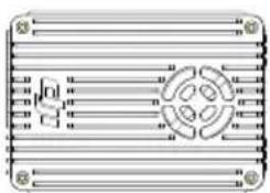 | 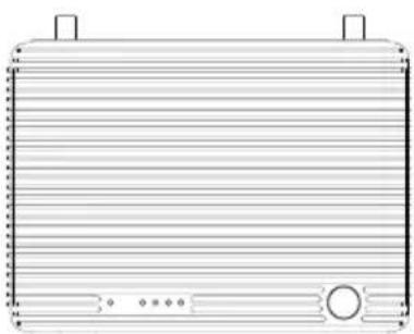 |
| Air system paddle antenna ×2 | Ground system antenna ×2 |
 |  |
Air System Cables
| GIMBAL cable ×1 (A) | |
| If used with PHANTOM 2, connect cable to reserved 6-PIN port on central board for air system power supply and OSD info input. |  |
| DBUS cable ×1 | |
| Connect to flight control system DBUS port for communication. |  |
| Air system power and CAN cable ×1 | |
| Connect to Air system GIMBAL port, one end for power, the other for CAN port. |  |
| AV cable ×1 | |
| Connect camera's AV output to AV input port. |  |
| HDMI cable (D-D) ×1 | |
| Connection for camera's HDMI output. |  |
| GIMBAL cable x1 (B) | |
| Use this cable to connect your gimbal's GCU port with the Lightbridge air system. |  |
Ground System Cables
| Remote control cable ×1 | |
| For remote control training port connection. Connect red port 1 to a remote control for aircraft control and black port 2 to a remote control for gimbal control. | 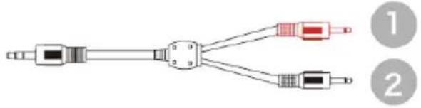 |
| Remote control training cable×1 | |
| Connect the red jack to the aircraft remote control to control. |  |
| Training port cables (rectangle) ×2 | |
| Remote control training port connection. |  |
| Charger ×1 | |
| Connect to ground system when charging. |  |
| USB upgrade cable ×1 | |
| Connect to a PC when upgrading firmware. |  |
| PHANTOM training port cable x1 | |
| Connect one end of the cable to the PHANTOM remote controller training port and the other end to the Lightbridge remote controller cable. |  |
Optional Packet
| Optional packet (1) | HDMI cable (D-D) ×1 |  |
| Ground system holder ×1 | 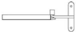 | |
| Smart phone holder ×1 | 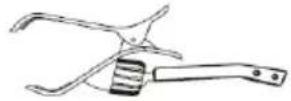 | |
| Optional packet (2) | HDMI cable for Zenmuse ×1 |  |
| PHANTOM training port cable x1 |  | |
| GIMBAL cable x1 (B) |  | |
| Optional packet (3) | Air system antenna extension cables x2 |  |
| Air system antenna mount x2 | 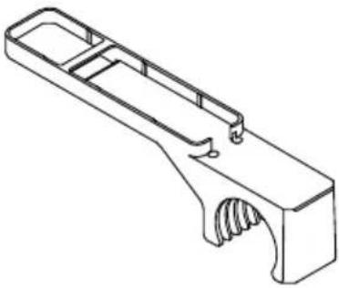 |
1 Introduction
1.1 Air system
Front View
![INTERNAL PORT V.V.L.HG-# DBLS UPGRADE LINK CONTROL VIDEO [ ] 1[ ][3][4][5][6]](/content/2026/05/760736/images/78a29030f3dbc76644efe2db09ab2ec865024c72d858f4622a0bcc683ee0f828.jpg)
[1] GIMBAL PORT
This port be connected to the G7 port on a DJI HD gimbal or to other ports for the functions listed below:
a) Power supply: (V+, V-) On-board battery (3S\~6S) power connection. Non-DJI HD gimbal users must use a separate power cable or air system power CAN cable to connect air system and on-board battery.
b) CAN-Bus: (L,H) OSD information from the flight system. For non-DJI HD gimbal users, connect to the CAN-Bus port (for DJI A2 user, use the CAN 1 Bus port) on the flight control system with a seperated CAN-Bus cable.
c) DVSB: (G-,+) DVSB video input from DJI HD gimbal.
[2] DBUS port
Connect built in receiver interface to DJI flight control system DBUS port, usually located on the main controller labled X2. No other receiver required when DBUS is used. The A2's built in receiver will automatically be disabled when DBUS port is used.
[3] UPGRADE port
Connect to PC to upgrade firmware using DJI LIGHTBRIDGE Assistant.
[4] LINK button
Press to link air system with ground system.
[5] CONTROL indicator
Remote control link indicator displays commutation status of air and ground systems.
| Indicator | Description | Action |
![DJI Lightbridge - [1] GIMBAL PORT - 1](/content/2026/05/760736/images/34ef34171c53130cc31fac0b3e04a385e617d1803a6a1324779a281331404719.jpg) | Linking in progress. | Link button has been pressed. Air system is attempting to link with ground system. |
![DJI Lightbridge - [1] GIMBAL PORT - 2](/content/2026/05/760736/images/daa2ad49ccaf4c3f34564d12f12a84fea6f9945628eaf4046def1422c057cfca.jpg) | Signal detected but not linked. | Link required. |
![DJI Lightbridge - [1] GIMBAL PORT - 3](/content/2026/05/760736/images/ddab80f477c4adb4640ccee7d2f80efb50d7afb9f1f07aaba14a0a57b0303c0d.jpg) | Successful link. | Normal. |
![DJI Lightbridge - [1] GIMBAL PORT - 4](/content/2026/05/760736/images/9b709b453c014dc62cd0d5c94c317ae86de32e1191e274ba2beefd1ee31d3321.jpg) | No detected signal. | Power on Ground system. Check distance between ground and air systems. |
[6] VIDEO indicator
Video link indicator shows video source transmission status.
| Indicator | Description | Instruction |
![DJI Lightbridge - [6] VIDEO indicator - 1](/content/2026/05/760736/images/a21ae72d3016fad48681f293d3cb448c1048ce22d8d2f35312a8ffaa5cb07e9c.jpg) | AV/HDMI signal detected and functioning normally. | Normal. |
![DJI Lightbridge - [6] VIDEO indicator - 2](/content/2026/05/760736/images/30e5b06a71781023f3b30de0f9102f4d940c4c2103998973477a8fd016f6dad2.jpg) | AV/HDMI signal detected. Transmission failed. | Air system or ground system power cycle required. |
![DJI Lightbridge - [6] VIDEO indicator - 3](/content/2026/05/760736/images/82620e90e6a51fe169a648f11c7b92ba149cbc2f2e5ae0dff29947caef80cb2f.jpg) | No video source detected. | Check camera and connection. |
Top View
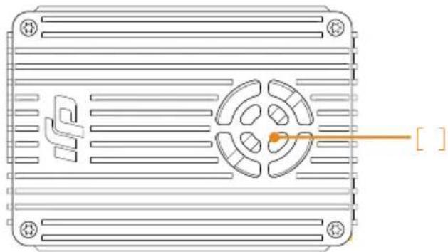
natural_image
Technical line drawing of a rectangular electronic device with internal components and mounting holes (no text or symbols)[1] Ventilation inlet
Do not obstruct ventilation fan outlet to ensure maximum cooling efficiency.
Side View
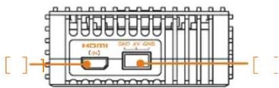
[1] HDMI IN Port
Connect to HDMI input device. Maximum input rate is 1920*1080@60fps.
[2] AV Port
Connect to AV input, including:
a) AV output from camera
b) AV output from DJI AV gimbal control unit (GCU)
1.2 Ground System
Front View
![[ ] 1 [ ] 2 UPPENS CONTROL IN HDMI USB OUT [3] [4] [5]](/content/2026/05/760736/images/dcba77d0c383f3d595b4403b11c1034e4702061cb3b298c5c07f2db3531bab89.jpg)
[1] Power Adapter Port (11V\~26V)
Connect to power adapter or 3S\~6S battery to charge built-in battery. When ground system is connected with an external power adapter or battery, the built-in battery will disable. Ensure the input voltage range does not exceed the operating range of 12\~24V. Use supplied charger to charge the battery.
[2] UPGRADE Port
Connect to PC to upgrade firmware through DJI LIGHTBRIDGE Assistant.
[3] CONTROL IN Port
Connect to training port on remote control using remote control cable and rectangle headed training port cable. Connect gimbal and aircraft controllers to control both simultaneously. 2.4GHz remote controls must be connected to this port with RF switched off to avoid interference. Remote controls working at other frequencies cannot be connected to the Control In port using the remote control link.
[4] HDMI OUT Port
Connect to HDMI supported monitor for video viewing. Maximum output rate is 1080i60.
[5] USB Port
Connect to smart device to view video and flight control system OSD using DJI LIGHTBRIDGE App.
Top View
![[1] [2] [3]](/content/2026/05/760736/images/2711c19a1ec9daa946e0d750c52f67757bb1e7d30526d13fb37bb5d8a7fed386.jpg)
[1] VIDEO Indicator
Vedio like indicator displays connection status between air and ground systems.
| Indicator | Description |
| Signal detected from air system. Ground system working normally. | |
| No signal from air system. Ground system working normally. |
[2] POWER Indicator
Battery capacity display for ground system.
| Indicator | Battery Capacity |
| 87.5%~100% | |
| 75%~87.5% | |
| 62.5%~75% | |
| 50%~62.5% | |
| 37.5%~50% | |
| 25%~37.5% | |
| 12.5%~25% | |
| 0%~12.5% | |
| = 0% |
![DJI Lightbridge - [2] POWER Indicator - 1](/content/2026/05/760736/images/a76b073a3e03ded2c3b93054ed70d13790e170b076ed9b8cc418e9ca57ea0bba.jpg)
![DJI Lightbridge - [2] POWER Indicator - 2](/content/2026/05/760736/images/cf8a920fd30ce65079df014b55a11a9b6872d785fd9c2d5ce7b84837e4873c97.jpg)
![DJI Lightbridge - [2] POWER Indicator - 3](/content/2026/05/760736/images/8cb2da21e8aa0abe3a4ffa982c3b6210139d1b094067e3728110e9f92fd24c77.jpg)
[3] POWER Button
Power on: When battery is off, press power button once, then again and hold for 2 seconds to power on. Power off: When battery is off, press power button once, then again and hold for 2 seconds to power off. Show capacity: When battery is off, press power button once to display battery capacity.
2 Installation
2.1 Air System Installation
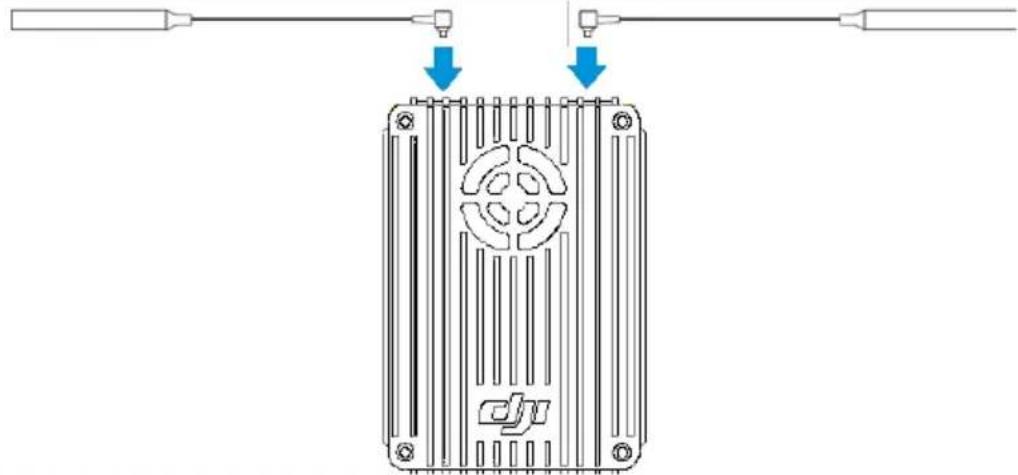
2.1.1 Installing Antennas
Insert antennas into positions shown below. Ensure they click into place.
natural_image
Diagram of a DC motor with labeled pins and wiring, showing internal components and connection points (no text or symbols)Notes
(1) Install antennas before powering on air system.
(2) Point antennas downward when in use and avoid obstructions to ensure transmission quality.
(3) Use only DJI antennas and install them correctly. Other antennas are incompatible.
(4) Do not unplug the antennas unless it is absolutely necessary. Use tweezers to clamp on the metal part of the antennas when unplugging the antennas. Do not apply excessive force on the antennas otherwise it may cause damages to the antennas.
(5) For use with large aircraft. Connect the antenna extension cable to the panel antenna before attaching the air system.
(6) Designed for DJI Spreading Wings aircraft. Place the panel antenna into the antenna mount, and then place the antenna mount onto the landing gear of the aircraft. Note that the panel antenna should be at a 90 degree angle to the landing gear. Watch the video tutorials on the DJI website for more detail
2.2 Ground System Installation
2.2.1 Installing Antennas
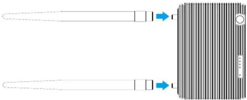
Attach two antennas to ground system according to example below. Screw them in tight.
natural_image
Diagram showing two elongated objects with arrows pointing to a textured rectangular object (no text or symbols present)Notes
(1) Attach antennas before powering on to avoid damage.
(2) Use only DJI antennas and install them correctly. Other antennas are incompatible.
2.2.2 Remote Control Connection
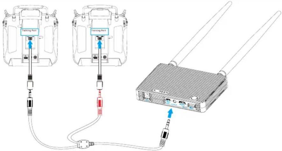
Connect training port and Control In port on ground system using rectangle headed training port cable and remote control cable. Supported remote controls include Futaba, Spektrum, Devention and JR. Refer to remote control manuals for details.
Two remote controls can be connected to the ground system at once. See example below for details.
● Red jack connects to aircraft remote control.
- Black jack connects to gimbal remote control.
Notes
(1) 2.4GHz remote controls must be connected to ground system for aircraft and gimbal control through training ports, whose RF function should be switched off. Ground system will relay signals, remote
control will act as control system.
(2) 5.8GHz remote controls cannot be connected to ground system. Remote control signal is transmitted by the remote control itself. Flight control system will communicate with receiver at 5.8GHz. Additionally, DBUS on air system does not need connection.
2.2.3 Remote Control Configuration
Remote control must be configured through Assistant for the flight control system before performing this step. Pay special attention to the below:
-
Select AERO as TX model. Set all curves (pitch, throttle, expo, rates, etc.) to default. Set endpoints of all channels to default (100%) and all trims and sub-trims to zero.
-
Check all channel outputs are "Basic" -> "RC" page.
Refer to remote control manual for configuration. The below configuration process is based on a Futaba T8FG.
- Switch off RF.
a) Press and hold "RTN" button to switch on remote control.
b) Enter "POWER MODE" menu, select "RF OFF".
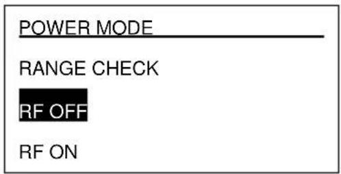
c) RF indicator will turn off.
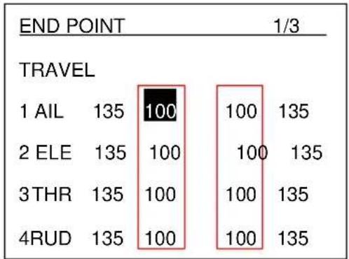
- Set "TRAVEL" value of each channel within 100.
a) Double click "LINK" button to enter "LINKAGE" menu. Select "END POINT".
b) Enter "END POINT" menu, set "TRAVEL" value of each channel within 100.
other
END POINT 1/3 | TRAVEL | 135 | 100 | | :--- | :--- | :--- | | 1 AIL | 135 | 100 | | 2 ELE | 135 | 100 | | 3 THR | 135 | 100 | | 4RUD | 135 | 100 | | Travel | 135 | 100 | | Travel | 135 | 100 | | Travel | 135 | 100 | | Travel | 135 | 100 | | Travel | 135 | 100 | | Travel | 135 | 100 | | Travel | 135 | 100 | | Travel | 135 | 135 | End PointNote
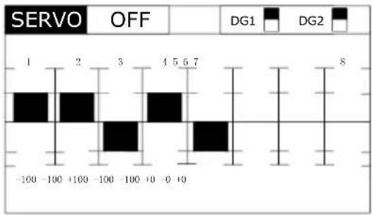
In some cases (namely Futaba T8J remote controls), actual “TRAVEL” value may exceed 100 even when set to correctly. This inconsistency can be observed by viewing the “SERVO” in the “LINKAGE”, as shown below. Actual GUI may vary between models.
bar
SERVO OFF | Position | DG1 | DG2 | |---|---|---| | 1 | -100 | -100 | | 2 | -100 | -100 | | 3 | -100 | -100 | | 4 | -100 | -100 | | 5 | -100 | -100 | | 6 | -100 | -100 | | 7 | -100 | -100 | | 8 | -100 | -100 |Check that actual "TRAVEL" value does not exceed 100. If it does, reconfigure as necessary.
2.2.4 Video Output Connection
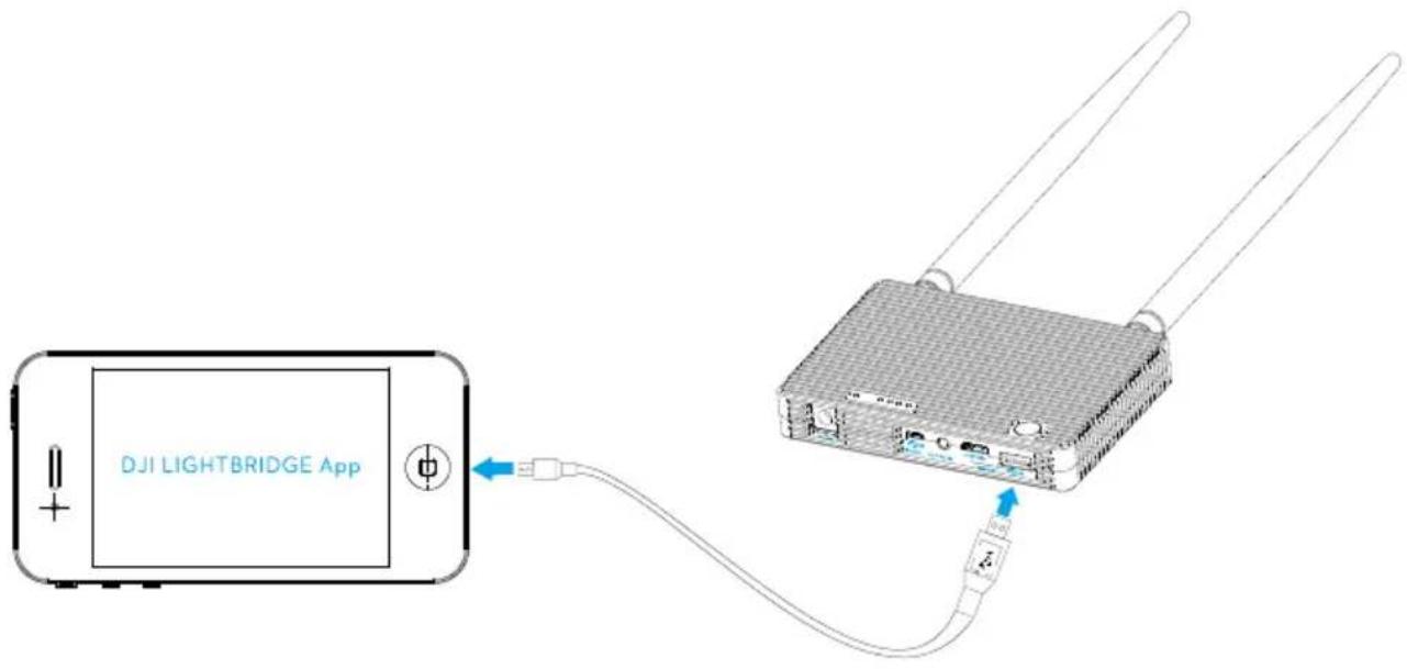
HDMI and USB ports output video, however the output options are mutually exclusive. Select either HDMI or USB output base on your choice of device.
- Connect monitor with HDMI support to HDMI Out port on ground system for video.
- Connect smart device to USB port on ground system with USB cable. Use DJI LIGHTBRIDGE App for video and OSD. The below example uses the USB port connection.
Note
Do not attach HDMI and USB devices to the ground system simultaneously. This will cause HDMI device to
2.3 Connection Scenario
DJI LIGHTBRIDGE offers several solutions to connect the gimbal to the flight controller based on gimbal model. This section provides information about the most commonly seen solutions and their connection diagram. Follow the connection described in the solutions that best suits your requirements.
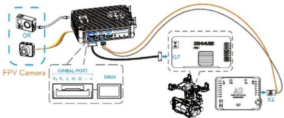
2.3.1 DJI HD Gimbal
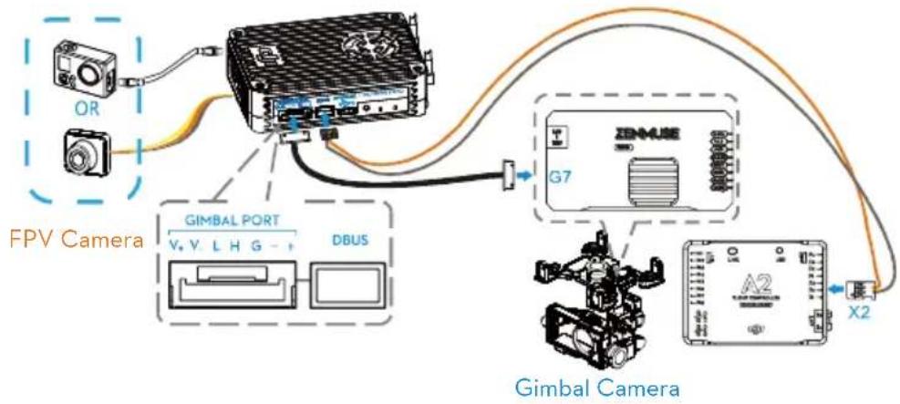
When using with DJI HD gimbal such as Z15-BMPCC, you can select either single or dual video source. By single video source mode, it means the air system relays either the gimbal camera video or the FPV camera video signal to the ground system. These two video sources are mutually exclusive under single video source mode. On the hand, the air system simultaneously relays gimbal camera and FPV camera video signal to the ground system. The ground system can one of the video signal from the air system. Note that video output source is defaulted to "HDMI/AV", user should manually select "HD gimbal" when they are connecting DJI HD gimbal to the air system.
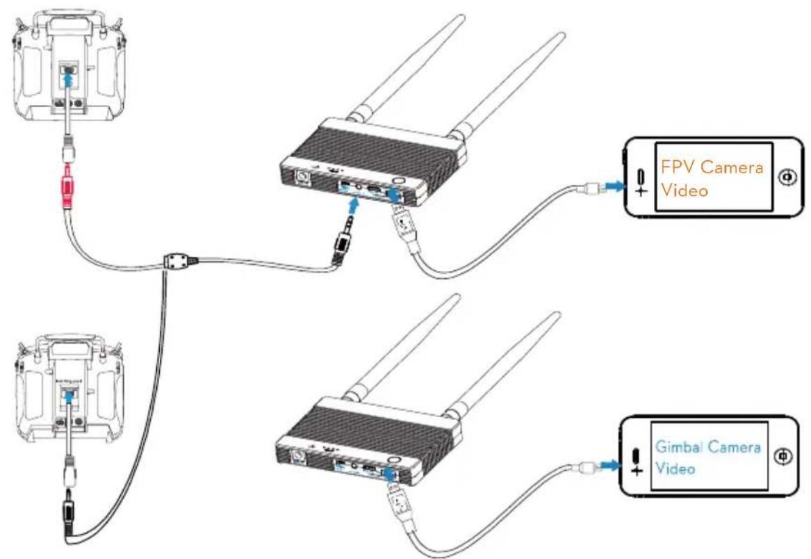
Scenario 1 - Dual Video Source with Dual Remote Control
Use two remote controls to control gimbal and aircraft independently. Map the gimbal and aircraft control channels to both of the remote controls through DJI LIGHTBRIDGE Assistant. In dual video source mode, aircraft operator receives the FPV camera video feed from the master ground station, while the gimk operator receives DJI HD gimbal video feed from the slave ground station.
Air system connection :
- Connect Gimbal Port on air system to G7 port on DJI HD gimbal with supplied Gimbal cable (DJI HD gimbal).
- Connect HDMI /AV port to the FPV camera.
- Connect DBUS port on air system to DBUS port (X2 port) on flight control system with DBUS cable.
- Refer to gimbal and flight control system manuals to complete connection.
Ground system connection :
- Connect remote control to the ground station via training port.
- Connect mobile devices or HDMI monitor to the master and slave ground station.
- Launch DJI LIGHTBRIDGE App and configure the Master - Slave mode in "App Settings". It is recommended to use "Master" ground system to receive FPV video signal and "Slave" ground
system to receive gimbal video signal.
flowchart
graph TD
    A["OR"] --> B["FPV Camera"]
    C["Camera"] --> B
    B --> D["GIMBAL PORT"]
    D --> E["DBUS"]
    E --> F["Gimbal Camera"]
    F --> G["X2"]
    F --> H["G7"]
    H --> I["ZENMUSE"]
flowchart
graph TD
    A["Camera Module 1"] -->|Wireless Connection| B["FPV Camera Video"]
    C["Camera Module 2"] -->|Wireless Connection| D["Gimbal Camera Video"]
    B -->|Wireless Connection| E["FPV Camera Video"]
    D -->|Wireless Connection| F["Gimbal Camera Video"]
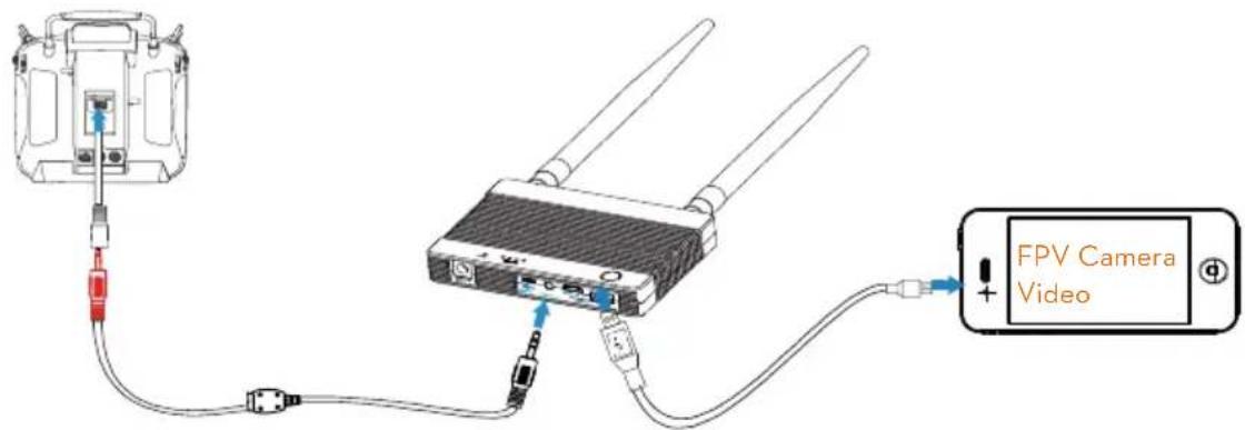
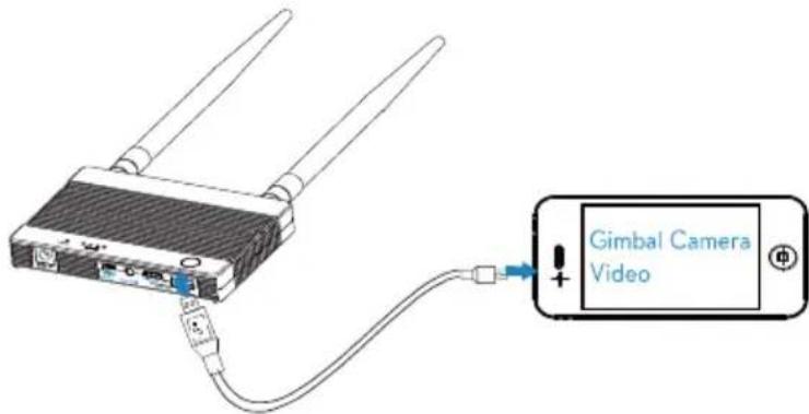
Scenario 2 - Dual Video Source with Single Remote Control
Use single remote control to control gimbal and aircraft independently. Map the gimbal and aircraft control channels to the remote control through DJI LIGHTBRIDGE Assistant. In single video source mode, aircraft operator receives the FPV camera video feed from the master ground station, while the gimbal operator receives DJI HD gimbal video feed from the slave ground station.
Air system connection :
- Connect Gimbal Port on air system to G7 port on DJI HD gimbal with supplied Gimbal cable (DJI HD
gimbal).
- Connect HDMI /AV port to the FPV camera.
- Connect DBUS port on air system to DBUS port (X2 port) on flight control system with DBUS cable.
- Refer to gimbal and flight control system manuals to complete connection.
Ground system connection :
- Connect remote control to the ground station via training port.
- Connect mobile devices or HDMI monitor to the master and slave ground station.
- Launch DJI LIGHTBRIDGE App and configure the Master -Slave mode in "App Settings". It is recommended to use "Master" ground system to receive FPV video signal and "Slave" ground system to receive gimbal video signal.
flowchart
graph TD
    A["OR"] --> B["FPV Camera"]
    B --> C["GIMBAL PORT"]
    C --> D["DBUS"]
    D --> E["ZENMUSE"]
    E --> F["X2"]
    F --> G["Control Module"]
    G --> H["Robot"]
    style A fill:#f9f,stroke:#333
    style B fill:#ccf,stroke:#333
    style C fill:#cfc,stroke:#333
    style D fill:#fcc,stroke:#333
    style E fill:#cff,stroke:#333
    style F fill:#ffc,stroke:#333
    style G fill:#cfc,stroke:#333
    style H fill:#fcc,stroke:#333
Gimbal Camera
Scenario 3 - Single Video Source with Dual Remote Control
Use two remote controls to control gimbal and aircraft independently. Map the gimbal and aircraft control channels to both of the remote controls through DJI LIGHTBRIDGE Assistant. In single video source mode, the aircraft operator and gimbal operator use different remote control to reduce interferences.
Air system connection :
- Connect Gimbal Port on air system to G7 port on DJI HD gimbal with supplied Gimbal cable (DJI HD gimbal).
- Connect DBUS port on air system to DBUS port (X2 port) on flight control system with DBUS cable.
- Refer to gimbal and flight control system manuals to complete connection.
Ground system connection :
- Connect remote control to the ground station via training port.
- Connect mobile devices or HDMI monitor to the master and slave ground station.
- Ground station displays DJI HD gimbal video signal.
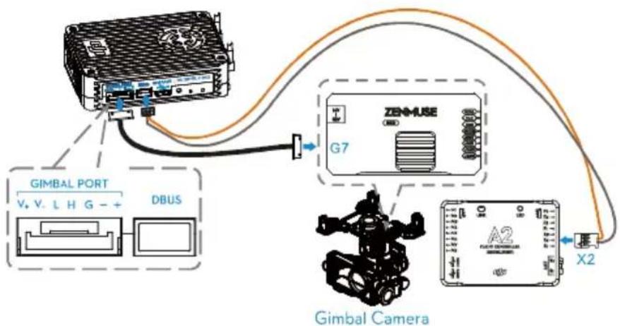
flowchart
graph TD
    A["GIMBAL PORT V. V. L H G - + DBUS"] --> B["DBUS"]
    B --> C["ZENMUSE"]
    C --> D["G7"]
    D --> E["X2"]
    E --> F["Gimbal Camera"]
    F --> G["A2"]
    style A fill:#f9f,stroke:#333
    style B fill:#ccf,stroke:#333
    style C fill:#cfc,stroke:#333
    style D fill:#fcc,stroke:#333
    style E fill:#cff,stroke:#333
    style F fill:#ffc,stroke:#333
    style G fill:#fcc,stroke:#333
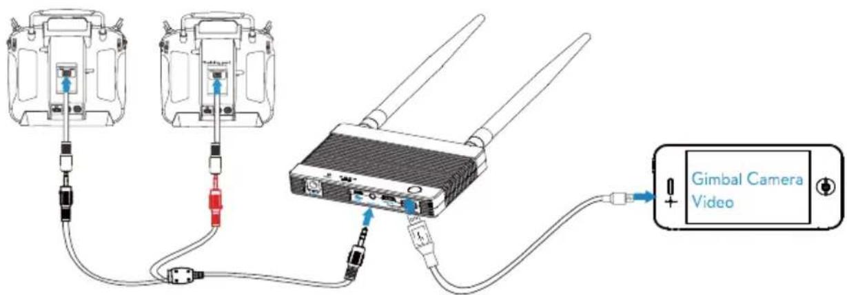
Scenario 4 - Single Video with Single Remote Control
Use two single controls to control both gimbal and aircraft. Map the gimbal and aircraft control channels to a single remote controls through DJI LIGHTBRIDGE Assistant.
Air system connection :
- Connect Gimbal Port on air system to G7 port on DJI HD gimbal with supplied Gimbal cable (DJI HD gimbal).
- Connect DBUS port on air system to DBUS port (X2 port) on flight control system with DBUS cable.
- Refer to gimbal and flight control system manuals to complete connection.
Ground system connection :
- Connect remote control to the ground station via training port.
- Connect mobile devices or HDMI monitor to the master and slave ground station.
- Ground station displays DJI HD gimbal video signal.
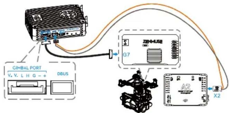
flowchart
graph TD
    A["GIMBAL PORT"] -->|V. V. L H G - +| B["DBUS"]
    A --> C["ZEN-MASE"]
    C --> D["X2"]
    D --> E["Robot"]
    style A fill:#f9f,stroke:#333
    style B fill:#ccf,stroke:#333
    style C fill:#cfc,stroke:#333
    style D fill:#fcc,stroke:#333
    style E fill:#cff,stroke:#333
Gimbal Camera
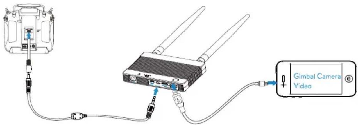
2.3.2 DJI non-HD Gimbal
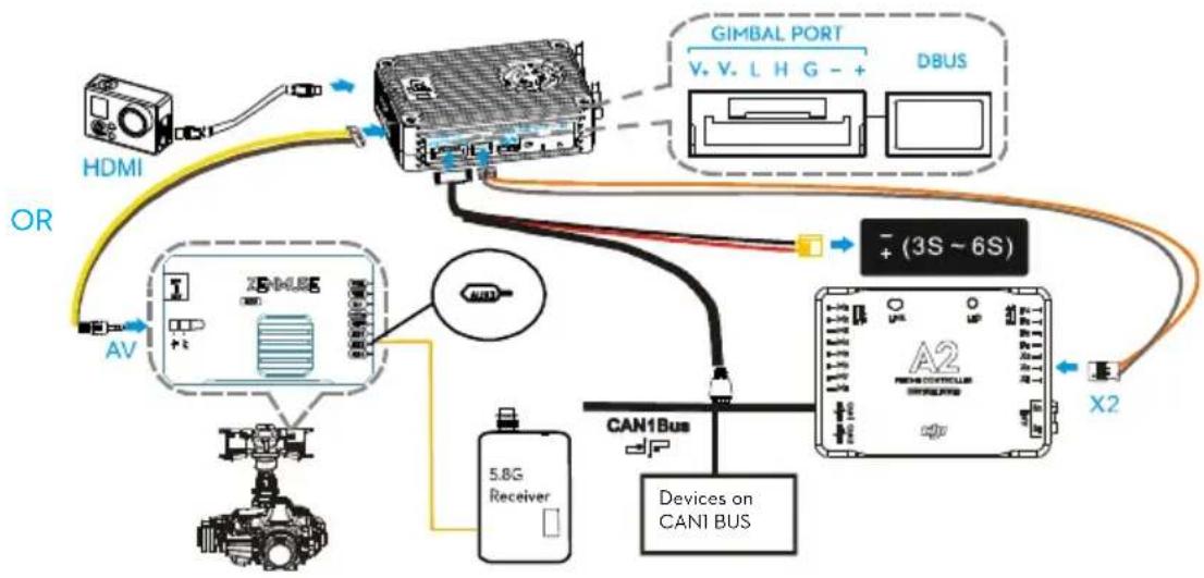
When using with DJI non-HD gimbal such as Z15-GH3, connect AV output from DJI gimbal to AV input port on the air system. When using camera that has HDMI output, connect HDMI output from the camera to the HDMI input port on the air system. It is possible to control air craft and gimbal using single remote control, as long as proper channel mapping is completed in DJI LIGHTBRIDGE Assistant. It is also possible to control the gimbal independently with a 5.8GHz receiver, in this scenario, it is required to connect the 5.8GHz receiver to the AUX2 port on the DJI gimbal.
Scenario 5 - DJI non-HD gimbal with 5.8GHz receiver
- Connect either HDMI or AV port on the air system to the HDMI or AV port according to the choice of the camera.
- Connect Gimbal Port to onboard battery and CAN-bus port on DJI flight control system (CAN1 port for DJI A2 users) via the supplied air system power and CAN cable.
- Connect DBUS to DBUS port (X2 port) on flight control system with DBUS cable.
- Connect 5.8GHz receiver to the AUX2 port on the DJI non-HD gimbal GCU, when using 5.8GHz receiver to control the gimbal.
- Refer to gimbal and flight control system manuals to complete connection.
Below example is based on DJI Z15-5D gimbal and A2 flight control system with 5.8GHz receiver. - A CAN-Hub or iOSD Mark II is required to provide extra CAN ports, if there is not enough CAN port.
flowchart
graph TD
    A["HDMI"] -->|OR| B["USB"]
    B --> C["CAN1 Bus"]
    C --> D["A2 NEHDCOMPLI 5.8G Receiver"]
    D --> E["Device on CAN1 BUS"]
    E --> F["X2"]
    G["GIMBAL PORT V. V. L H G - + DBUS"] --> C
    H["AV"] --> B
    I["+ (3S ~ 6S)"] --> C
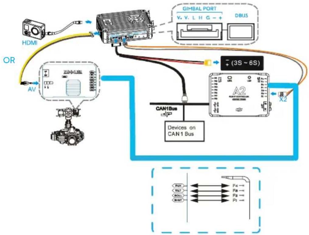
Scenario 6 - DJI non-HD gimbal with Single Remote Control
It is possible to control both aircraft and gimbal with single remote control as long as proper channel mappings is completed through DJI LIGHTBRIDGE Assistant. Follow the instructions below to complete the connections:
- Connect either HDMI or AV port on the air system to the HDMI or AV port according to the choice of the camera.
- Connect Gimbal Port to onboard battery and CAN-bus port on DJI flight control system (CAN1 port for DJI A2 users) via the supplied air system power and CAN cable.
- Connect DBUS to DBUS port (X2 port) on flight control system with DBUS cable.
- Connect PAN, TILT, ROLL and SHUT port on the gimbal to F4,F3,F2,F1 port on A2 flight controller
- Refer to gimbal and flight control system manuals to complete connection.
- A CAN-Hub or iOSD Mark II is required to provide extra CAN ports, if there is not enough CAN port.
flowchart
graph TD
    A["HDMI"] -->|OR| B["Analog/Video Device"]
    B --> C["DBUS"]
    C --> D["GIMBAL PORT V.V.L.HG-+"]
    D --> E["Device 3S-6S"]
    E --> F["A2"]
    F --> G["CAN1 Bus"]
    G --> H["Devices on CAN1 Bus"]
    H --> I["X2"]
    I --> J["Output Line"]
    style A fill:#f9f,stroke:#333
    style B fill:#ccf,stroke:#333
    style C fill:#cfc,stroke:#333
    style D fill:#fcc,stroke:#333
    style E fill:#cff,stroke:#333
    style F fill:#ffc,stroke:#333
    style G fill:#cfc,stroke:#333
    style H fill:#fcc,stroke:#333
    style I fill:#ffc,stroke:#333
2.3.3 Phantom 2 Mode
Due to the absence of trainer port on Phantom remote control, it is not possible to connect the standard Phantom remote control to the ground system. User needs to replace the standard Phantom remote control with PPM
2.4GHz remote control (e.g. Futaba series). It is also possible to use DJI 5.8GHz remote control to replace the standard Phantom remote control. In this scenario, it is not required to connect the DBUS cable with flight controller. For more information about how to install air system to Phantom 2, visit DJI official website.
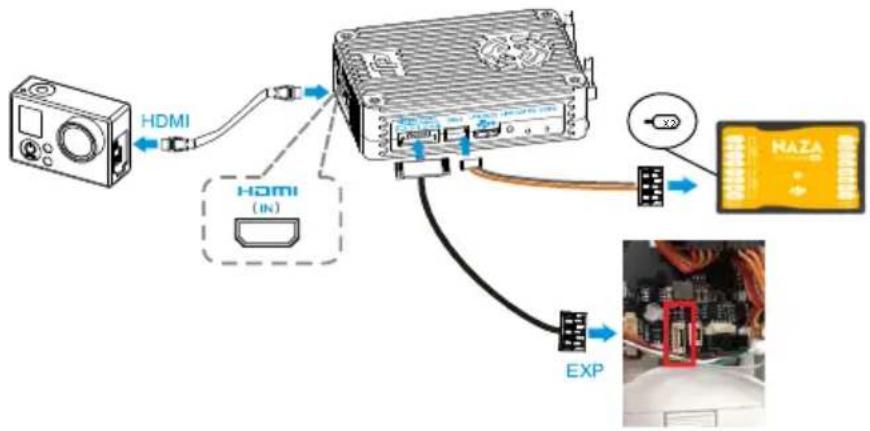
Scenario 7 - Phantom 2 with 2.4GHz Remote Control
- Connect HDMI IN port to HDMI out port on camera with HDMI cable.
- Connect Gimbal Port to EXP port (6-pin port) on DJI Phantom 2 central board with Gimbal cable. To access the EXP port, you will need to remove the top of the DJI Phantom 2 case. See below example for details.
- Connect DBUS port on air system with X2 port on the flight controller.
flowchart
graph TD
    A["Device"] -->|HDMI| B["Inverter"]
    B --> C["Exhibit 1"]
    B --> D["Exhibit 2"]
    B --> E["Exhibit 3"]
    B --> F["Exhibit 4"]
    B --> G["Exhibit 5"]
    style A fill:#f9f,stroke:#333
    style B fill:#ccf,stroke:#333
    style C fill:#cfc,stroke:#333
    style D fill:#fcc,stroke:#333
    style E fill:#cff,stroke:#333
    style F fill:#ffc,stroke:#333
    style G fill:#fcc,stroke:#333
Note :
- Linking is required when using with PPM 2.4GHz receiver.
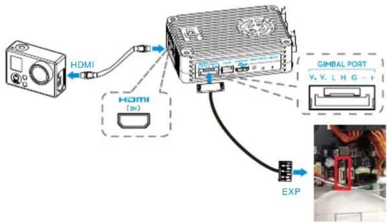
Scenario 8 - Phantom 2 with 5.8GHz Remote Control
- Connect HDMI IN port to HDMI out port on camera with HDMI cable.
- Connect Gimbal Port to EXP port (6-pin port) on DJI Phantom 2 central board with Gimbal cable. To access the EXP port, you will need to remove the top of the DJI Phantom 2 case. See below example for details.
Note :
- Aircraft will need to be modified to accommodate 5.8GHz receiver.
2.3.4 Phantom 2 Vision+ Mode
Scenario 9 - Phantom 2 Vision+ with DJI Lightbridge
To use Phantom 2 Vision+ with DJI Lightbridge, visit DJI WIKI page on DJI official website
(http://wiki.dji.com/en/index.php/Using a_DJI_Phantom_2_Vision%2B_with_the_DJI_Lightbridge) for details.
2.3.5 DIY Mode
Only HDMI and AV port is available for video transmission under DIY mode.
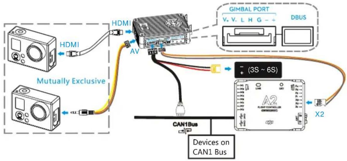
Scenario 10 - DIY mode
DIY users should select either HDMI or AV based on camera video output and follow the below connection procedures:
- On AV cameras, connect AV port to AV output with AV cable. On HDMI cameras, connect HDMI IN port to the HDMI out with HDMI cable.
- Connect Gimbal Port to onboard battery and CAN-bus port on DJI flight control system (CAN1 port for DJI A2 users) via the supplied air system power and CAN cable.
- Connect DBUS to DBUS port (X2 ports) on flight control system with DBUS cable.
- Refer to flight control system manuals to complete connection.
The below example is based on DJI A2.
flowchart
graph TD
    A["Device 1"] -->|HDMI| B["Switch"]
    C["Device 2"] -->|HDMI| B
    B --> D["AV"]
    D --> E["Device 3"]
    E --> F["CAN1Bus"]
    F --> G["Device 4"]
    G --> H["Device 5"]
    H --> I["Device 6"]
    I --> J["Device 7"]
    J --> K["Device 8"]
    K --> L["Device 9"]
    L --> M["Device 10"]
    M --> N["Device 11"]
    N --> O["Device 12"]
    O --> P["Device 13"]
    P --> Q["Device 14"]
    Q --> R["Device 15"]
    R --> S["Device 16"]
    S --> T["Device 17"]
    T --> U["Device 18"]
    U --> V["Device 19"]
    V --> W["Device 20"]
    W --> X["Device 21"]
    X --> Y["Device 22"]
    Y --> Z["Device 23"]
    Z --> AA["Device 24"]
    AA --> AB["Device 25"]
    AB --> AC["Device 26"]
    AC --> AD["Device 27"]
    AD --> AE["Device 28"]
    AE --> AF["Device 29"]
    AF --> AG["Device 30"]
    AG --> AH["Device 31"]
    AH --> AI["Device 32"]
    AI --> AJ["Device 33"]
    AJ --> AK["Device 34"]
    AK --> AL["Device 35"]
    AL --> AM["Device 36"]
    AM --> AN["Device 37"]
    AN --> AO["Device 38"]
    AO --> AP["Device 39"]
    AP --> AQ["Device 40"]
    AQ --> AR["Device 41"]
    AR --> AS["Device 42"]
    AS --> AT["Device 43"]
    AT --> AU["Device 44"]
    AU --> AV["Device 45"]
    AV --> AW["Device 46"]
    AW --> AX["Device 47"]
    AX --> AY["Device 48"]
    AY --> AZ["Device 49"]
    AZ --> BA["Device 50"]
    BA --> BB["Device 51"]
    BB --> BC["Device 52"]
    BC --> BD["Device 53"]
    BD --> BE["Device 54"]
    BE --> BF["Device 55"]
    BF --> BG["Device 56"]
    BG --> BH["Device 57"]
    BH --> BI["Device 58"]
    BI --> BJ["Device 59"]
    BJ --> BK["Device 60"]
    BK --> BL["Device 61"]
    BL --> BM["Device 62"]
    BM --> BN["Device 63"]
    BN --> BO["Device 64"]
    BO --> BP["Device 65"]
    BP --> BQ["Device 66"]
    BQ --> BR["Device 67"]
    BR --> BS["Device 68"]
    BS --> BT["Device 69"]
    BT --> BU["Device 70"]
    BU --> BV["Device 71"]
    BV --> BW["Device 72"]
    BW --> BX["Device 73"]
    BX --> BY["Device 74"]
    BY --> BZ["X2"]
3 Using DJI LIGHTBRIDGE
3.1 Master-Slave Mode
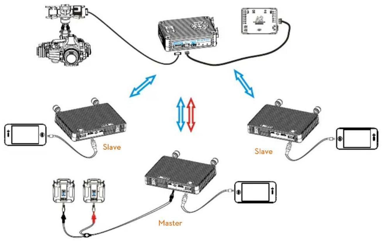
This is a one-to-multi transmission mode. Linked air and ground systems act as a broadcast master pair. Dual link transmission is carried out between the master pair. The master ground system receives video and relays remote control signals to the air system. Ground systems that have not been linked to the air system are slaves. Slaves can only receive video from the air system. The example below uses a DJI HD gimbal.
Legends:
 | Video link: HD transmission to ground system. |
 | Remote control signal link: Gimbal and aircraft control transmission. |
flowchart
graph TD
    A["Device 1"] -->|Blue double arrow| B["Slave"]
    C["Device 2"] -->|Blue double arrow| D["Slave"]
    E["Device 3"] -->|Blue double arrow| F["Slave"]
    G["Device 4"] -->|Blue double arrow| H["Slave"]
    I["Device 5"] -->|Blue double arrow| J["Master"]
    K["Device 6"] -->|Blue double arrow| L["Master"]
    M["Device 7"] -->|Blue double arrow| N["Master"]
    O["Device 8"] -->|Blue double arrow| P["Master"]
    Q["Device 9"] -->|Blue double arrow| R["Master"]
    S["Device 10"] -->|Blue double arrow| T["Master"]
    U["Device 11"] -->|Blue double arrow| V["Master"]
    W["Device 12"] -->|Blue double arrow| X["Master"]
    Y["Device 13"] -->|Blue double arrow| Z["Master"]
    AA["Device 14"] -->|Blue double arrow| AB["Master"]
    AC["Device 15"] -->|Blue double arrow| AD["Master"]
Note
Do not attempt to link slaves to the air system. This may compromise the communication between air system and master ground system. Ensure to set the slave as a slave in the DJI LIGHTBRIDGE app.
4 Using DJI LIGHTBRIDGE App
4.1 Downloading DJI LIGHTBRIDGE App
DJI LIGHTBRIDGE App can be downloaded in the following ways
| Downloading Approaches | |||
| 1 | 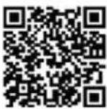 | Scan QR card for DJI LIGHTBRIDGE App download link. Install onto smart device. | |
| 2 | Android | Search “DJI LIGHTBRIDGE” in Google Play. Install DJI LIGHTBRIDGE App onto smart device. | |
| Pay attention to notifications from DJI.com and Google Play to keep DJI LIGHTBRIDGE App updated. | |||
| Supported Mobile Devices | |||
| Android ( Version 4.1.2 or later ) | Optimus G ProLG ElectronicsLG Electronics G2Samsung Galaxy Note3 qcom, N9005, N9006Samsung Galaxy Note3 Exynos, N900Samsung Galaxy S4Samsung Galaxy MegaSony Xperia Z(L36h)Sony Xperia Z Ultra(XL36h) | ||
4.2 Register and Login
![Full HD 1080 FULL HD EXPERIENCE 1920'1080@5.0fps input and 1920'1080@2.5fps output OSD information displayed on DUI Lightbridge app. Register Login [2]](/content/2026/05/760736/images/768820037dd6e0cacc7358a4a67c9f2f3efd2d8177a6df636de4a61ec8fa6d5b.jpg)
Note
Register online then log in.
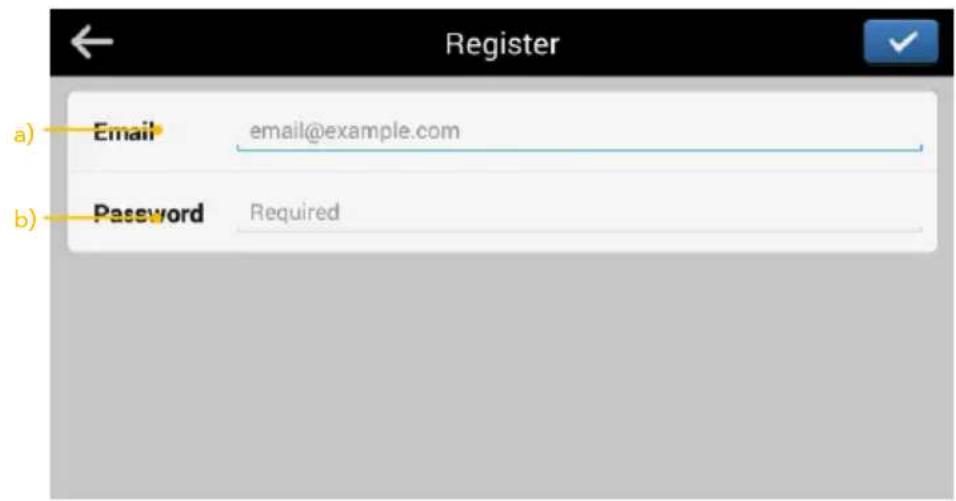
[1] Register
Tap 'Register' to enter registration page. Enter email and password then tap √ to create a new account.
Note
A DJI password can be used with all DJI Assistants and Apps.
[2] Login
Tap 'Login' to enter the login page. Enter registered email and password then tap √ to log in.
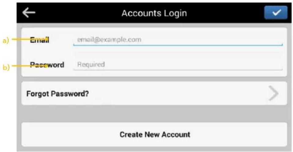
Notes
(1) Log into your account when time you launch DJI LIGHTBRIDGE App for the first time.
(2) If you have forgotten your password, select "Forgot password" to begin retrieval.
4.3 DJI LIGHTBRIDGE App Usage
DJI LIGHTBRIDGE App displays video and flight control system OSD information as shown below.
![[1] [2] [3] [4] [5] [6] [MODEL] GPS OFF 75% 100 10 G H: -0.0 m D: N/A m H: 0.0 m/s V: 0.0 m/s [7] [8] [9] [10] [11] [12] [13]](/content/2026/05/760736/images/6294f8fa1e6aba83863ecf288e9f52be08a7374739047e6d2e3509a5201732cf.jpg)
[1] Flight control system control mode.
[2] Flight status.
[3] Air system power voltage indicator.
[4] Video signal status.
[5] Remote control signal status. App sounds an alarm if the remote control signal is weak.
[6] GPS satellite count.
[7] Aircraft attitude/ Aircraft relative position.
[8] Flight altitude.
[9] Flight distance (Distance between current position and recorded Home point. Only displayed when GPS signal is normal and Go Home position has been recorded. Otherwise, N/A will be displayed.)
[10] Vertical speed.
[11] Horizontal speed.
[12] Live view.
[13] App settings.
4.4 DJI LIGHTBRIDGE App Settings
Setup the channels, transmission mode, master-slave mode, video source, HDMI, warning, signal diagnostic, etc. in the settings:
![Settings Adverse [1] Channels Manual > [2] Transmission mode Smooths mode > [3] Master-Slave Master mode > [4] Video source Single video source HD/MB/BA V.S. N/A](/content/2026/05/760736/images/8b043bdc89624988023222523330402df2861d8c4f4af1409403f847b32c7e93.jpg)
![Settings [5] HDMI > General Parameter unit Metric > [6] Warning > [7] Signal diagnostic > V.S. N/A](/content/2026/05/760736/images/92f178bcd9593d1a377e71d899b45f0164821fd0bf7802216fec1985bc287172.jpg)
[1] Channel Settings
Manually select the channel when the performance of auto-selected channel is not optimum. Shorter yellow bar indicates better channel signal quality. Once the channel is selected manually, it cannot auto switch, use this function cautiously.
| Mode | Description |
| Auto | Automatically select the least interfered channel among the 10 channels. [Recommended] |
| Manual | Manually select the channel. [Use cautiously] |
![DJI Lightbridge - [1] Channel Settings - 1](/content/2026/05/760736/images/f553d16ba5fcd9b18867af7bb8c82f73e3f6e73707f10208a82c831c7d3c8d02.jpg)
bar
| Channel | Value | | :--- | :--- | | 1 | -52.9 | | 2 | -51.8 | | 3 | -47.1 | | 4 | -41.6 | | 5 | -42.9 | | 6 | -40.4 | | 7 | -41.0 | | 8 | -40.5 | | 9 | -41.8 | | 10 | -42.0 |[2] Transmission Mode
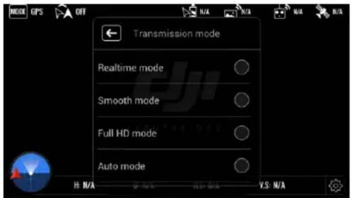
Select a transmission mode to adjust the video quality:
| Mode | Quality | Distance | Resolution |
| Real time | ★ | ★★★★ | 720p50/60 |
| Smooth | ★★ | ★★★ | 720p50/60 |
| Full HD | ★★★ | ★★ | 1080i50/60 |
| Auto | A transmission mode between 720p and 1080i will be automatically selected depending on channel conditions. | ||
Note
Transmission mode option is not available in dual video source setting.
[3] Master-Slave Mode Setting
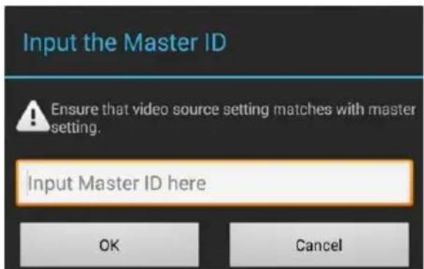
When single air system is paring with more than one ground system. Master-Slave setting is required. Master ground system can display video and relay control signal to the aircraft; slave ground system can only display video. Steps to setup:
A) Tap "Master-Slave" option in DJI LIGHTBRIDGE App of the master ground system, make a note of the master ID;
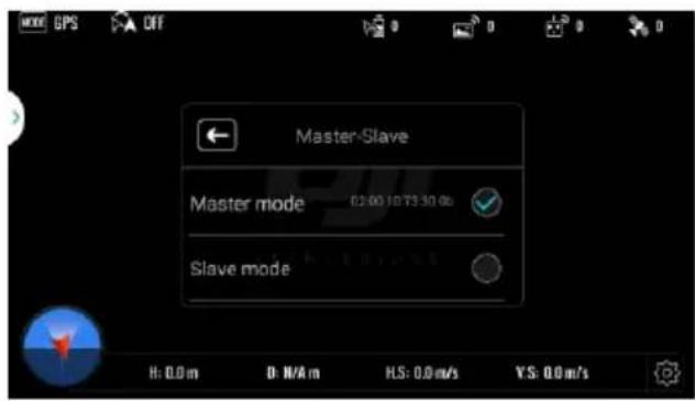
B) Tap "Master-Slave" option in slave ground system, enter master ID to connect.
[4] Video Source Setting
Dual video source input mode is available when connecting air system to a DJI HD gimbal. An extra video
source input (HDMI / AV) can be selected as video input. Ground system can select either of the video source to display. Note that transmission distance will be reduced in Dual Video Source mode.
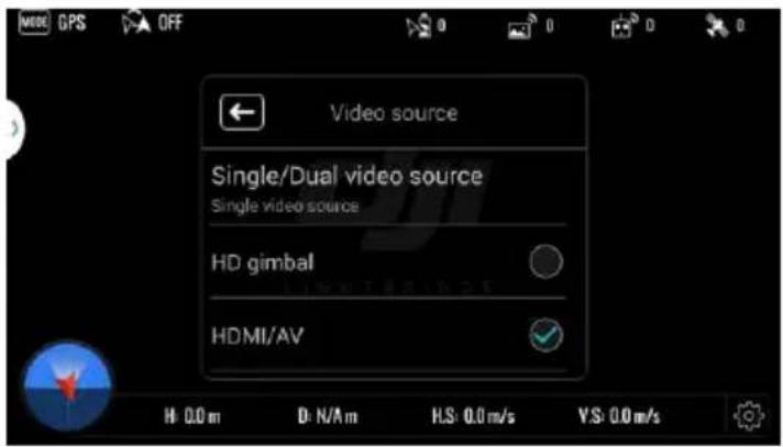
The table below shows video output mode based on the selection of single or dual video source on ground system:
| Single / Dual Video Source Setting | Video Source Input | Remark |
| Single Video | DJI HD gimbal | Only DJI gimbal video signal will be transmitted to the ground system. |
| HDMI/AV | Only HDMI/AV video signal will be transmitted to the ground system. | |
| Dual Video Source | DJI HD gimbal | Both DJI HD gimbal and HDMI/AV video signals are transmitted to the ground system. But only DJI HD gimbal video will be displayed. |
| HDMI/AV | Both DJI HD gimbal and HDMI/AV video signals are transmitted to the ground system. But only HDMI/AV will be displayed. |
[5] HDMI Settings
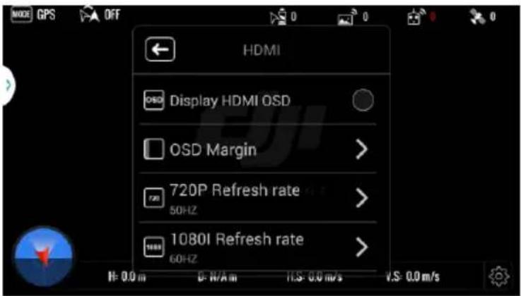
1) Display HDMI OSD: Enable or disable the OSD display on your HDMI device.
2) OSD Margin: Adjust the OSD position to fit HDMI displays of different sizes.
3) 720P Refresh Rate: Set the refresh rate to 50Hz or 60Hz in Realtime or Smooth mode.
4) 1080I Refresh Rate: Set the refresh rate to 50Hz or 60Hz in Full HD mode.
Note
The OSD is not available when AV video input is selected.
[6] Warning Settings
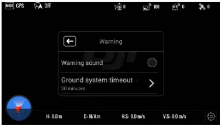
1) Alarm: Enable or disable the alarm.
If enabled, the app will set off an alarm in the following scenarios:
a) The aircraft battery is low.
b) The remote control's transmission signal has been lost.
2) Ground system timeout: Enable or disable ground system timeout. When enabled, if the ground system is idle for 30 minutes, an alarm will sound and the system will power off.
[7] Signal Diagnostic
![DJI Lightbridge - [7] Signal Diagnostic - 1](/content/2026/05/760736/images/8e5da0605341918f049173a2467a71f21a8165071a05ea90d6bc159db19795bf.jpg)
bar
| Antenna | Value | | ------- | ----- | | Antenna 1 | -17 | | Antenna 2 | -21 |If the maximum flight distance is significantly reduced, this could be caused by damaged antennas or a
poor antenna connection. Run signal diagnostics in the DJI LIGHTBRIDGE App to determine the cause.
- Remove one of the antennas, place ground system two meters away from air system and launch DJI LIGHTBRIDGE App. Enter "Signal Diagnostic" page to check the signal strength. Green bars indicates signal strength is normal, and readings should falls in the range of -20 to 40.
a) One red bar indicates ground system antenna is not working normally. Adjust ground system antennas orientation or replace the corresponding antennas. If the problem persists, it may indicate the antennas port on ground system is damaged. Contact technical support for assistance.
b) Two red bars indicate air system antenna is not working properly. Adjust air system antennas orientation or replace the corresponding antennas. If the problem persists, it may indicate the antennas port on air system is damaged. Contact technical support for assistance.
- Removed the tested antennas and replace with the remaining antenna. Run the diagnostics procedure above on the remaining antenna.
4.5 Using Ground System
- Power on air system then the ground system. Wait until POWER indicator light is on.
- VIDEO link indicator light on ground system will go solid green, followed by CONTROL link indicator on air system. VIDEO link indicator on air system will then flash green showing that ground and air systems are communicating normally.
- Launch DJI LIGHTBRIDGE App. If the live image appears, the system is working normally.
- Real time OSD information is available when the flight control system is working normally.
Notes
(1) Position air system antennas downward and ground system antennas upward. Ensure there are no obstacles between air system antennas and ground system antennas otherwise transmission distance may be affected.
(2) There will be an alarm if no picture shows or no operation in 30 minutes after ground system powering on. The alarm will disappeared if you operate the remote control, touch the App screen or press the power button in the next 10 minutes, or else the ground system will be power off automatically.
5 Assistant
LIGHTBRIDGE Assistant is required for optimum effectiveness. Windows is required.
5.1 Installing Driver and Assistant
- Download driver installer and Assistant installer .EXE files from the DJI LIGHTBRIDGE download page on www.dji.com.
- Connect either ground system or air system to PC using a Micro-USB cable.
- Run driver installer and follow prompts to finish installation.
- Run Assistant installer and follow prompts to finish installation.
- Double click LIGHTBRIDGE icon on the desktop to launch it.
Note
Installer only supports Windows operating systems (Win XP, Win7, Win8 (32 or 64 bit)).
5.2 Using Assistant
User can upgrade DJI LIGHTBRIDGE firmware, distribute the remote control channel and calibrate the remote control through LIGHTBRIDGE Assistant.
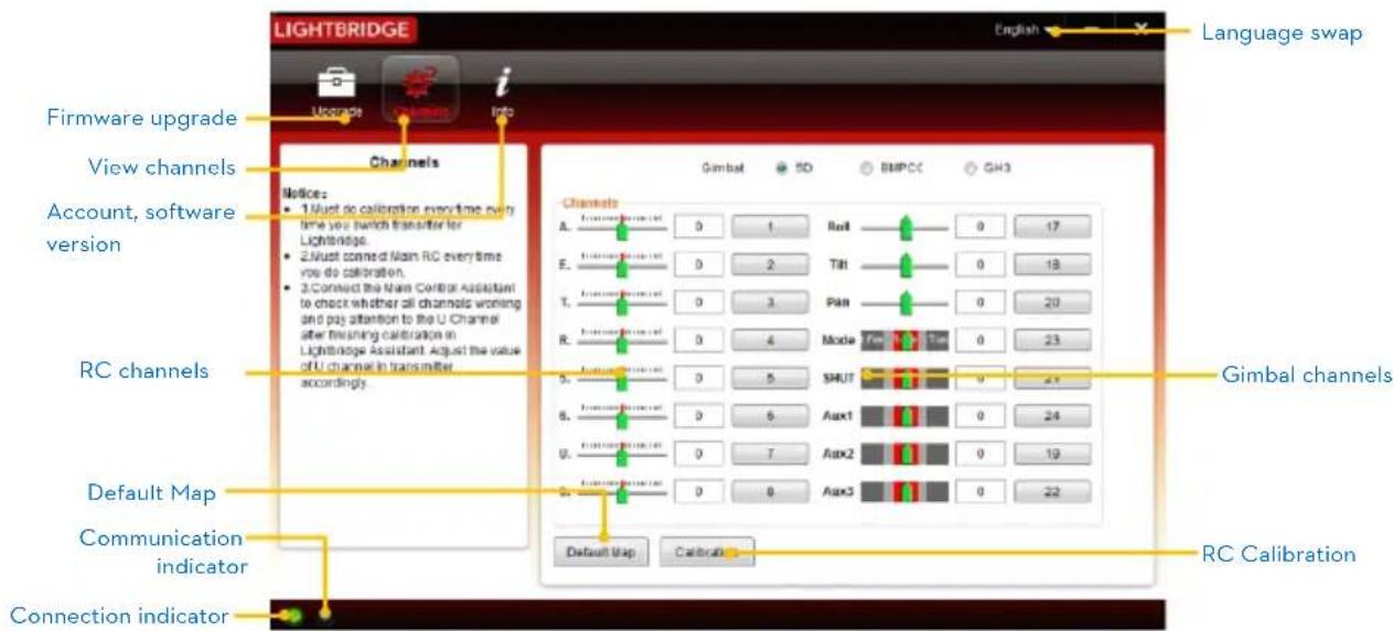
5.2.1 Using LIGHTBRIDGE Assistant
- Start up the PC and ground system then connect it to the PC with a Micro-USB cable. DO NOT disconnect until configuration is finished.
- Run LIGHTBRIDGE Assistant and wait for the ground system to connect. Watch the indicators on the bottom of the screen. When connected successfully, the connection indicator is green and solid on and communication indicator blinks blue.
- Go to "Channels" page to check both aircraft channels and gimbal channels.
5.2.2 Remote Control Channel Settings
If you change the remote control, it is necessary to set the channels again through LIGHTBRIDGE Assistant, so that the remote link function can be use normally. Steps to set up the remote channel:
- Connect the Remote Control to PC, enter the main page.
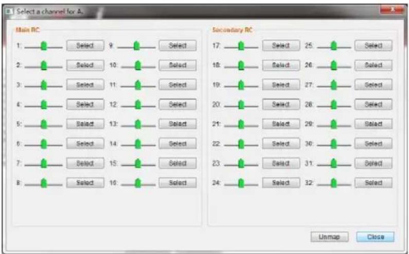
- Select "Default Map", as the page shown below:
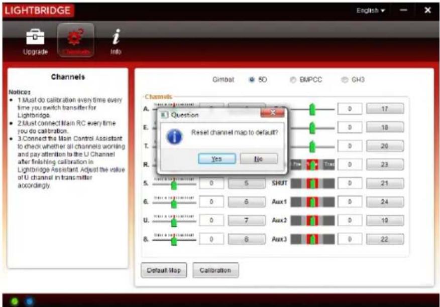
- Eight channels on the left are for aircraft and eight channel on the left are for gimbal control. Calibration is required.
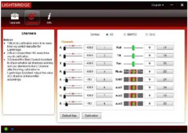
- Click "Calibration" and calibrate the remote control follow the instructions.
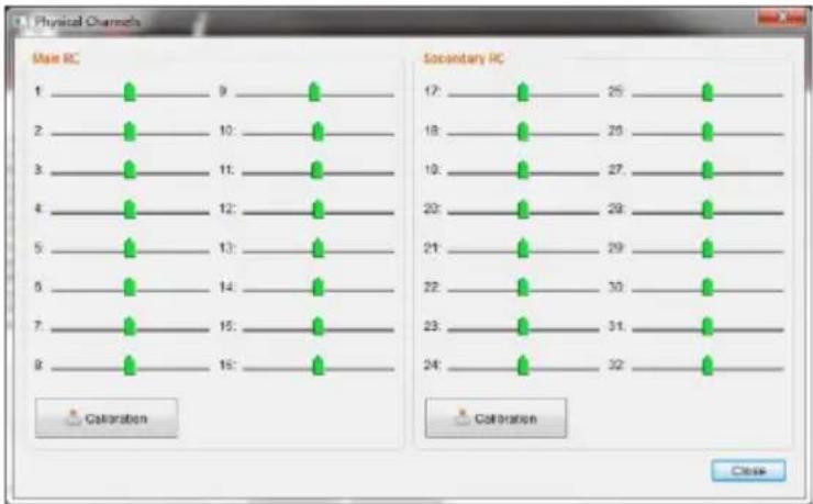
- After finish calibration, you can map the channel as you need. The following is the example for mapping gimbal SHUT channel.
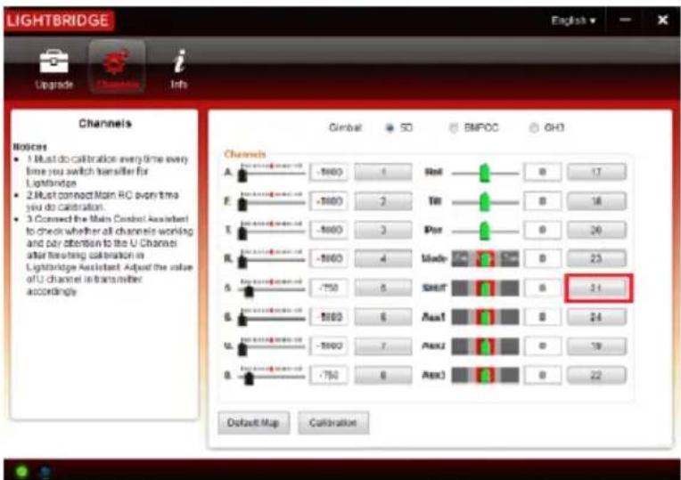
You can enter the mapping page by click the SHUT button.

- Toggle the desired SHUT switch on remote control, observe the variation to location the corresponding channel data. Click Select to finish mapping.
5.2.3 Firmware Upgrade
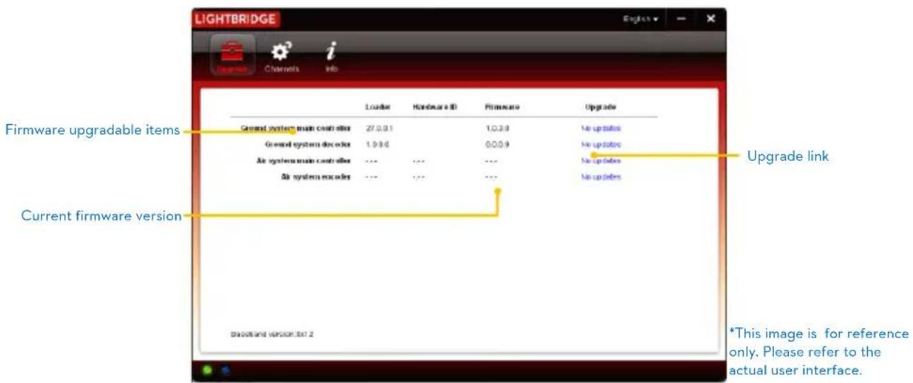
- Click "Upgrade" icon to check current firmware version and whether installed firmware is the latest version. If not, click the relative links to upgrade.
- Wait until Assistant displays the "finished" message then click OK. Power cycle the ground system (or air system) after 5 seconds. Once complete, firmware is up to date.
Notes
(1) Connect to ground system for ground system main controller and ground system decoder upgrade, and connect to air system for air system main controller and air system encoder upgrade,
(2) Internet connection is required for LIGHTBRIDGE firmware upgrade.
(3) DO NOT power off until upgrade is finished.
(4) If firmware upgrade fails, main controller will enter a waiting for firmware upgrade status automatically. Repeat the above.
6 Specification
| Performance Parameters | |
| Transmission Distance (outdoors and unobstructed) | 1.7 Km |
| EIRP | 100mW |
| Receiver Sensitivity (1%PER) | -101dBm ± 2dBm |
| Working Frequency | 2.4GHz ISM |
| Air System Antennas Gain | 2.0±0.7dBi@2450MHz |
| Ground System Antennas Gain | 5.0±0.7dBi@2450MHz |
| Physical Parameters | |
| Operating Temperature | -10~50°C |
| Dimension (no antennas) | ● Air system: 68mm(L)X48mm(W)X21mm(H)● Ground system: 125mm(L)X90mm(W)X20mm(H) |
| Gross Weight (no antennas) | ● Air system: 7lg● Ground system: 295g |
| Hardware Functions Supported | |
| Antenna Connector | MMCX Male (air system), SMA Male (ground system) |
| Air System Operating Voltage | 3S~6S |
| Ground System Operating Voltage | 3S~6S |
| Air System Operating Amperage | 700mA ± 20mA(@12V) |
| Ground System Operating Amperage | 600mA ± 10mA(@12V) |
7 Appendix
7.1 Supported DJI Products
Please upgrade to the latest firmware version.
| Flight Control System | DJI AV Gimbal | DJI HD Gimbal |
| A2 | Z15 | Z15-BMPCC |
| NAZA-M V2 | Z15-GH3 | Z15-GH4 (HD) |
| WooKong-M | Z15-5D | |
| Phantom 2 | H3-2D,H3-3D |
7.2 Relinking
Follow the below instructions to relink air and ground systems if link fails.
- Maintain a distance of 0.5m to 1m between air system and ground system. Power on air system then ground system.
- Press LINK button on air system with pin. Hold for 5 seconds then release.
- When relink is complete, CONTROL link indicator on air system will turn solid green.
7.3 Recharging Ground System
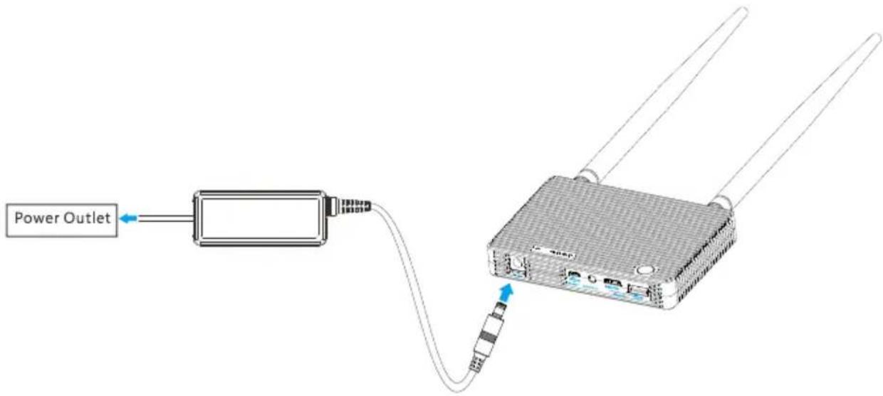
- Connect plug adapter to power adapter before attaching power adapter to ground system. Plug power adapter to power outlet to recharge.
- Power indicator lighting up green indicates charge in progress.
- Power indicator turning off indicates charge complete.
7.4 Supported Resolution
Following resolutions is supported.
| Mode | Format |
| AV | PAL25, NTSC30 |
| HDMI | 720p50, 720p60, 1080i50, 1080i60, 1080p25, 1080p30, 1080p50, 1080p60 |
DJI LIGHTBRIDGE supports above mentioned video format. The list below take GoPro Hero3+ as example:
| Camera | Resolution | HDMI Output | Supported | Remark |
| GoPro Hero3+ | 4k@15fps | 1080p60 | √ | Restart air system when switching between the resolutions settings. |
| 2.7k@24fps | 1080p60 | √ | ||
| 1440@30fps | N/A | × | ||
| 1080s@30fps | N/A | × | ||
| 1080@30fps | 1080p60 | √ | ||
| 1080@60fps | 1080p60 | √ | ||
| 1080@25fps | 1080p50 | √ | ||
| 1080@50fps | 1080p50 | √ | ||
| 960@60fps | 1080p60 | √ | ||
| 720@60fps | 1080p60 | √ | ||
| 720@120fps | 720p60 | √ | ||
| 720@50fps | 1080p50 | √ | ||
| 720@100fps | 720p50 | √ |
The above supported list is non-exhausted.
7.5 Supported Remote Control
| Brand | Model |
| FUTABA | T8FG |
| T14SG | |
| T10CHG | |
| T10CG | |
| T8J | |
| JR | DSX9 |
| DSX11 | |
| SPEKTRUM | DX6I |
| DX18 | |
| DEVENTION | DEVO-10 |
The above supported list is non-exhausted. Your device may be supported if it follows the same PPM signal standard as the devices above.
8 FAQ
- Q: Unable to download DJI LIGHTBRIDGE App from Google Play.
A: Follow one of the methods below to download or update the App.
■ Scan the QR code on the quick start guide to download.
Input the URL of "http://m.dji.net/lightbridge" in the address bar of browser to download.
If you have installed the App before, go to "Settings" -> "About" -> "Check new version" to update it.
- Q: Can I use 5.8GHz transmitter to control the gimbal?
A: Yes. Use the lever kit to control the gimbal on Phantom.
- Q: Can SBUS decoder decode the SBUS signal from the DJI LIGHTBRIDGE?
A: Yes.
- Q: Is it possible to use single FUTABA transmitter to simultaneously control aircraft and gimbal?
A: Yes. You will need to assign the channels from aircraft and gimbal through DJI LIGHTBRIDGE App.
- Q: Is it possible to two different brands of transmitter to simultaneously control aircraft and gimbal?
A: Yes. As long as both of the transmitter have PPM output.
- Q: How to solve the issue of aircraft losing control within couple hundred meters, accompany with blur screen?
A: Follow the instruction below to resolve this issue:
a) Check if the antenna installation location unobstructed. Try to keep both ends of the antennas as far as possible. Keep away from metal.
b) Ensure antennas face downward and make sure antennas is intact, otherwise, it may lead to transmission lost.
c) Check if the antennas is firmly attached to the air system.
d) Run signal diagnostics in the DJI LIGHTBRIDGE App to determine the cause. Remove one of the antennas, place ground system two meters away from air system and launch DJI LIGHTBRIDGE App. Enter “Signal Diagnostic” page to check the signal strength. Green bars indicates signal strength is normal, and readings should falls in the range of -20 to 40. If not, adjust ground system antennas orientation.
e) Repeat step a,b,c. If problem persists, replace antenna.
f) Contact DJI tech support for assistance.
| 7. Q: Aircraft enters failsafe when using DJI LIGHTBRIDGE air system. | |
| A: Calibrate remote control through DJI LIGHTBRIDGE Assistant after connect the remote control to ground system. Fine tune the End Point value for channel U. | |
| 8. Q: Can we install two air systems on the same aircraft? | |
| A: No. | |
| 9. Q: My on-board camera has WiFi and Bluetooth function, can I turn them on during the flight? | |
| A: No, ensure that you have disabled WiFi and Bluetooth on your camera, otherwise it may interfere air system transmission. | |
| 10. Q: How to improve GPS searching time? | |
| A: Check if HDMI cable stays too close to the GPS module. Maintain 15cm distance between HDMI cable and GPS module. | |
| 11. Q: Air system VIDEO indicator turns solid red when connecting with BMPCC gimbal, is that normal? | |
| A: BMPCC gimbal has its own encoding system, therefore it does not rely on air system for encoding. Hence air system VIDEO indicator blinks green is work as design. | |
| 12. Q: Green lines appear on screen. | |
| A: Check if the output resolution or format is supported by DJI LIGHTBRIDGE. | |
| 13. Q: Green lines appear on screen. Air system VIDEO indicator blinks red after rebooting and also no video output from ground system, what should I do? | |
| A: Air system VIDEO indicator blinks red indicating no video output or unsupported video outp format. Check the following to resolve this issue:a) Check if the on-board camera is powered on. Connect the camera to a display device to check whether the signal output is normal. If video output is normal, check whether the video output format is supported by DJI LIGHTBRIDGE.b) Examine the HDMI cable condition, should the condition of the HDMI cable is not mint, replace the HDMI cable.c) Contact DJI technical support team if the problem persists. | |
| 14. Q: Ground system CONTROL LED blinks green. | |
| A: Blinking green indicator means linking is required. Check the follow to ensure linking is carried out correctly.a) Antennas are firmly attached on both air system and ground system.b) Launch DJI LIGHTBRIDGE App to check whether ground system is in master mode, if not, | |
| change to master mode.c) If linking process does not complete within 2 minutes. Redo linking. Do not place multiple ground systems in the same area before linking proceed.d) If the problem persist, contact DJI technical support team. | |
| 15. Q: Can I recharge ground system with battery? | |
| A: No. Recharge ground system with DJI standard power adaptor. | |
| 16. Q: Both air and ground system indicator blink solid green. But no video display on the Android mobile device. What should I do? | |
| A: Follow the instruction below to resolve the issue:a) Connect ground system to a HDMI monitor to eliminate the possible error from the ground system.b) Ensure Android OS version is at least 4.1.2 on the mobile device. And the “Allow USB Debugging” option is enabled on your android device.c) Check the version of your DJI LIGHTBRIDGE App.d) Launch DJI LIGHTBRIDGE App, make a note on the USB connection status on the GUI. Unplug the USB cable on the ground system. And then plug it back in. The USB connection status should changes from “USB disconnected” to “USB connected”.e) Should the problem persists, contact DJI technical support team. |
FCC and IC Statements
This device and its antenna must not be located or operating in conjunction with any other antenna and transmitter.
This device complies with part 15 of the FCC rules. Operation is subject to the following two conditions: (1) this device may not cause harmful interference, and (2) this device must accept any interference received, including interference that may cause undesired operation.
NOTE: The manufacturer is not responsible for any radio or TV interference caused by unauthorized modifications to this equipment. Such modifications could void the user's authority to operate the equipment.
NOTE: This equipment has been tested and found to comply with the limits for a Class B digital device, pursuant to part 15 of the FCC Rules. These limits are designed to provide reasonable protection against harmful interference in a residential installation. This equipment generates uses and can radiate radio frequency energy and, if not installed and used in accordance with the instructions, may cause harmful interference to radio communications. However, there is no guarantee that interference will not occur in a particular installation. If this equipment does cause harmful interference to radio or television reception, which can be determined by turning the equipment off and on, the user is encouraged to try to correct the interference by one or more of the following measures:
- Reorient or relocate the receiving antenna.
- Increase the separation between the equipment and receiver.
-Connect the equipment into an outlet on a circuit different from that to which the receiver is connected.
-Consult the dealer or an experienced radio/TV technician for help.
Changes or modifications not expressly approved by the party responsible for compliance could void the user's authority to operate the equipment.
Air system
This radio transmitter (11805A-201402240) has been approved by Industry Canada to operate with the antenna types listed below with the maximum permissible gain and required antenna impedance for antenna type indicated. Antenna types not included in this list, having a gain greater than the maximum gain indicated for that type, are strictly prohibited for use with this device.
| Manufacturer | Model | Connect Type | Maximum Gain | Impedance |
| INVAX System Technology Corp. | AN2400-06169GMX | MMCX Male | 2.7 dBi | 50 Ohm |
Ground system
This radio transmitter (11805A-201402241) has been approved by Industry Canada to operate with the antenna types listed below with the maximum permissible gain and required antenna impedance for antenna type indicated. Antenna types not included in this list, having a gain greater than the maximum gain indicated for that type, are strictly prohibited for use with this device.
| Manufacturer | Model | Connector Type | Maximum Gain | Impedance |
| INVAX System Technology Corp. | AN2400-9297SM | SMA Male | 5.7 dBi | 50 Ohm |
This device complies with Industry Canada licence-exempt RSS standard(s). Operation is subject to the following two conditions: (1) this device may not cause interference, and (2) this device must accept any interference, including interference that may cause undesired operation of the device.
When using the device, ensure that the antenna of the device is as least 20 cm away from all persons.
Hereby, SZ DJI TECHNOLOGY CO. LTD declares that this device is in compliance with the essential requirements and other relevant provisions of Directive 1999/5/EC.
- Profile
- Caution
- Assembly Cautions
- Usage Cautions
- Others
- Contents
- In the Box
- Introduction
- Air system
- [1] GIMBAL PORT
- [6] VIDEO indicator
- Top View
- [1] Ventilation inlet
- Side View
- [1] HDMI IN Port
- [2] AV Port
- Ground System
- Front View
- [1] VIDEO Indicator
- [2] POWER Indicator
- [3] POWER Button
- Installation
- Air System Installation
- Installing Antennas
- Notes
- Ground System Installation
- Installing Antennas
- Remote Control Connection
- Remote Control Configuration
- Note
- Video Output Connection
- Connection Scenario
- DJI HD Gimbal
- Scenario 1 - Dual Video Source with Dual Remote Control
- Air system connection :
- Ground system connection :
- Scenario 2 - Dual Video Source with Single Remote Control
- Scenario 3 - Single Video Source with Dual Remote Control
- Scenario 4 - Single Video with Single Remote Control
- DJI non-HD Gimbal
- Scenario 5 - DJI non-HD gimbal with 5.8GHz receiver
- Phantom 2 Mode
- Scenario 7 - Phantom 2 with 2.4GHz Remote Control
- Scenario 8 - Phantom 2 with 5.8GHz Remote Control
- Phantom 2 Vision+ Mode
- Scenario 9 - Phantom 2 Vision+ with DJI Lightbridge
- DIY Mode
- Scenario 10 - DIY mode
- Using DJI LIGHTBRIDGE
- Master-Slave Mode
- Using DJI LIGHTBRIDGE App
- Downloading DJI LIGHTBRIDGE App
- Register and Login
- [1] Register
- [2] Login
- DJI LIGHTBRIDGE App Usage
- DJI LIGHTBRIDGE App Settings
- [1] Channel Settings
- [2] Transmission Mode
- [3] Master-Slave Mode Setting
- [4] Video Source Setting
- [6] Warning Settings
- [7] Signal Diagnostic
- Using Ground System
- Assistant
- Installing Driver and Assistant
- Using Assistant
- Using LIGHTBRIDGE Assistant
- Remote Control Channel Settings
- Firmware Upgrade
- Appendix
- Supported DJI Products
- Relinking
- Recharging Ground System
- Supported Resolution
- Supported Remote Control
- FAQ
- FCC and IC Statements
- Air system
- Ground system
Brand : DJI
Model : Lightbridge
Category : Wi-Fi repeater