
VCT-FS7 - Tripod SONY - Free user manual and instructions
Find the device manual for free VCT-FS7 SONY in PDF.

| Product Type | Professional Tripod |
| Brand | Sony |
| Model | VCT-FS7 |
| Maximum Load Capacity | 5 kg (11 lbs) |
| Maximum Height | 150 cm (59 in) |
| Minimum Height | 60 cm (23.6 in) |
| Folded Length | 70 cm (27.6 in) |
| Weight | 3.2 kg (7.1 lbs) |
| Material | Aluminum Alloy |
| Leg Sections | 3 |
| Head Type | Fluid Head with Counterbalance |
| Pan & Tilt Drag | Adjustable 0-3 |
| Quick Release Plate | Yes, standard (Sony compatible) |
| Spirit Level | Yes, on base |
| Bubble Level | Yes, on head |
| Removable Pan Handle | Yes, 2 positions |
| Mid-Level Spreader | Included |
| Rubber Feet | Yes, retractable |
| Spike Feet | Included as alternative |
| Power Supply | No power needed (manual operation) |
| Maintenance | Clean with dry cloth; avoid solvents |
| Safety | Do not exceed load; secure camera properly |
| Spare Parts Availability | Contact Sony support for replacement parts |
Frequently Asked Questions - VCT-FS7 SONY
User questions about VCT-FS7 SONY
0 question about this device. Answer the ones you know or ask your own.
Ask a new question about this device
Download the instructions for your Tripod in PDF format for free! Find your manual VCT-FS7 - SONY and take your electronic device back in hand. On this page are published all the documents necessary for the use of your device. VCT-FS7 by SONY.
USER MANUAL VCT-FS7 SONY
Light Weight Rod Support
取扱説明書
Operating Instructions
Mode d'emploi
Bedienungsanleitung
© 2014 Sony Corporation Printed in Japan

安全のために
B-3
natural_image
Technical line drawing of a mechanical assembly with no visible text or symbolsD
E
B-1
natural_image
Mechanical component diagram showing a lever mechanism with no visible text or symbolsB-4
natural_image
Technical line drawing of a mechanical assembly with no visible text or symbolsF
natural_image
Technical line drawing of a video camera with attached sensor and control panel (no text or symbols)B-2
C
natural_image
Technical line drawing of a mechanical assembly with a clamping tool (no text or symbols)©

Before operating the unit, please read this manual thoroughly and retain it for future reference.
For the customers in the U.S.A.
SONY LIMITED WARRANTY - Please visit http://www.sony.com/psa/warranty for important information and complete terms and conditions of Sony's limited warranty applicable to this product.
For the customers in Canada
SONY LIMITED WARRANTY - Please visit http://www.sonybiz.ca/solutions/Support.do for important information and complete terms and conditions of Sony's limited warranty applicable to this product.
For the customers in Europe
Sony Professional Solutions Europe - Standard Warranty and Exceptions on
Standard Warranty. Please visit http://www.pro.sony.eu/warranty for important information and complete terms and conditions.
For the customers in Korea
SONY LIMITED WARRANTY - Please visit http://bpeng.sony.co.kr/handler/BPAS-Start for important information and complete terms and conditions of Sony's limited warranty applicable to this product.
The VCT-FS7 is an accessory that attaches to Sony PXW-FS7 camcorders to improve camera stability when shooting. Attaching the unit to the PXW-FS7 also enables the camera to be mounted on a VCT-14/VCT-U14 tripod attachment.
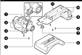
Name and function of parts A
① Front base
② Φ15 rod attachment hole (left and right) for the front base
③ Rod lock levers (left and right)
sed when attaching or removing the 15 rods.
When attaching, turn the lock rod levers clockwise to secure the rods.
when removing, turn the lock rod levers counterclockwise to loosen the levers.
If a lever is in a position that is difficult to turn, pull the lever out and turn it to
a position where it will be easier to operate. Then, push the lever back in
(Figure A)
Notes
• After attaching, check that the rods cannot come out.
- The maximum load is 4 kg (8 lb 13 oz) when using two rods.
- Do not use the camera shoulder belt when a heavy object is attached to
the rods.
4 Retaining screws (+B M3×8) for front base
⑤ Rosette mounts (left and right)
Attachment points for generic hand grips.
Note
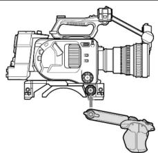
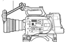
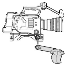
The PXW-FS7 grip remote control arm should be attached not to the
PXW-FS7 directly, but instead to the grip mounting point on this unit (Figure
F)
⑤ Adjustable shoulder pad
⑦ Retaining screw (3/8 in.) for rear base
Retaining screws (+B M3×8) for rear base
⑨ Rod lock levers (left and right)
Used when attaching or removing the 15 rods.
When attaching, turn the lock rod levers clockwise to secure the rods.
When removing, turn the lock rod levers counterclockwise to loosen the
levers.
If a lever is in a position that is difficult to turn, pull the lever out and turn it to
a position where it will be easier to operate. Then, push the lever back in.
Notes
• After attaching, check that the rods cannot come out.
- The maximum load is 4 kg (8 lb 13 oz) when using two rods.
- Do not use the camera shoulder belt when a heavy object is attached to
the rods.
10 Φ15 rod attachment holes (left and right) for the rear base
⑪ Rear base
Attaching to a camcorder
Removing the PXW-FS7 shoulder pad (Figure B-1)
move the PXW-FS7 shoulder pad.
Note
ore the shoulder pad in a safe place.
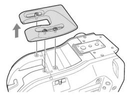
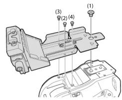
Attaching the rear base (Figure B-2)
Align the supplied screws with the screw holes on the camcorder in the
quence (1)→(2)→(3)→(4), then tighten securely.
Notes
- The base will not be attached correctly if the screws are attached in the wrong
sequence.
- tighten the four screws securely.
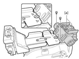
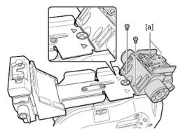
Attaching the front base (Figure B-3)
Align the supplied screws with the screw holes on the camcorder.
Push the front base into the rear base, so that there are no gaps at the points indicated by the marks on the front base, then tighten the two supplied
indicated by the 1 - thanks on the front base, then tighten the two suppli- screws and the two recessed assembly screws (la) in the figure) securely
Note
Tighten the four screws securely.
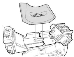
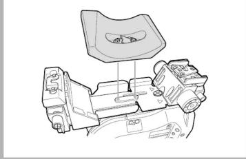
Attaching the adjustable shoulder pad (Figure B-4)
Align the two screws of the adjustable shoulder pad with the holes on the
camcorder, then alternately tighten the two screws.
Lower the orange shoulder pad lock lever to secure the shoulder pad.
Note
Alternately tighten the screws evenly.
Adjusting the shoulder pad position
Lift the shoulder pad lock lever to unlock it, slide the shoulder pad forward/
backward to the desired position, then lower the lever to lock the shoulder pad in position.
Note
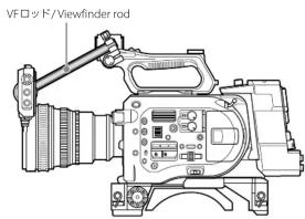
If the position of the variable-type shoulder pad is set to the front-most position, the length of the viewfinder rod may be insufficient (Figure G). In this case, use a different viewfinder rod (P/N: 4-547-069-11), which is 20mm (13/16 in.) longer than the standard rod. For details, consult your Sony sales representative.
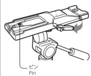
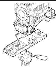
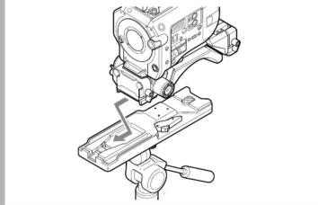
Attaching to the tripod attachment
Slide the camera forward along the groove until it clicks into place (Figure C)
Note
Wiggle the camera back and forth to make sure it does not come off.
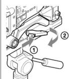
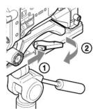
Detaching from the tripod attachment
Press and hold the red button (①), then slide the lever in the direction of the arrow (②) (Figure D).
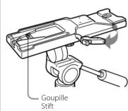
Note
If the pin on the tripod attachment does not return to its original position after detaching the camera, press and hold the button again and slide the lever in the direction of the arrow to return the pin to its original position. The camera cannot be mounted if the pin remains exposed (Figure E).
Specifications
Dimensions (W / H / D) Approx. 118 × 63.2 × 250 mm (4 ^3/4 × 2 ^1/2 × 9 ^7 / _8 inches) Mass Unit: 980 g (2 lb 2.6 oz), Rod (1): 160 g (5.6 oz) Supplied items Operating Instructions (2), screws (+B M3×8) (10), screw (3/8 in.) (1), Φ15 rods (2)
Design and specifications are subject to change without notice.
Notes
- Always verify that the unit is operating properly before use. SONY WILL NOT BE LIABLE FOR DAMAGES OF ANY KIND INCLUDING, BUT NOT LIMITED TO, COMPENSATION OR REIMBURSEMENT ON ACCOUNT OF THE LOSS OF PRESENT OR PROSPECTIVE PROFITS DUE TO FAILURE OF THIS UNIT, EITHER DURING THE WARRANTY PERIOD OR AFTER EXPIRATION OF THE WARRANTY, OR FOR ANY OTHER REASON WHATSOEVER. - SONY WILL NOT BE LIABLE FOR CLAIMS OF ANY KIND MADE BY USERS OF THIS UNIT OR MADE BY THIRD PARTIES. - SONY WILL NOT BE LIABLE FOR THE TERMINATION OR DISCONTINUATION OF ANY SERVICES RELATED TO THIS UNIT THAT MAY RESULT DUE TO CIRCUMSTANCES OF ANY KIND.
A
B-4
natural_image
Technical line drawing of a mechanical assembly with no visible text or symbolsG
Tige de viseur / Sucherschiene
natural_image
Line drawing of a professional video camera with extended arm and control panel (no text or symbols)Français
natural_image
Diagram of a mechanical component with a handle and mounting holes, showing internal structure without any text or symbols.C
natural_image
Technical line drawing of a sewing machine with a clamping tool (no text or symbols)D
E
B-3
natural_image
Technical line drawing of a mechanical assembly with no visible text or symbolsF
natural_image
Technical line drawing of a mechanical device with no visible text or symbols■2017, 2018 and 2019 are differently stated