
XBTN401 - Commande SCHNEIDER - Free user manual and instructions
Find the device manual for free XBTN401 SCHNEIDER in PDF.


| Product Type | Operator Terminal (HMI) |
| Brand | Schneider Electric |
| Model | XBT N401 |
| Category | Command / Display Unit |
| Display Type | Backlit LCD, 122 x 32 pixels |
| Display Capacity | 1 to 4 lines of 5 to 20 characters |
| Backlight Colors | Green, Orange, Red |
| Power Supply | 24 V DC, 200 mA max |
| Power Connection | 3-wire removable terminal block (pitch 5.08 mm, clamping 1.5 mm²) |
| Serial Communication | RS232 / RS485 via 25-pin SubD female |
| Supported Protocols | Modbus Master and Slave, Uni-Telway |
| Printer Port | MiniDIN connector |
| Keypad | 8 keys (4 customizable), plus 2 service keys and 2 navigation keys |
| Indicator Lights | 6 LEDs: Communication, Alarm, and 4 PLC-controlled |
| Maximum Application Pages | 200 (plus 256 alarm pages) |
| Protection Rating Front | IP65 (NEMA Type 4, 4X) |
| Protection Rating Rear | IP20 |
| Operating Temperature | 0 to +55 °C |
| Storage Temperature | -20 to +60 °C |
| Relative Humidity | 0 to 85% (non-condensing) |
| Mounting | Flush mount, panel thickness 1.5 to 6 mm |
| Dimensions (approx.) | 100 x 150 x 30 mm (estimated) |
| Weight (approx.) | 0.5 kg (estimated) |
| Maintenance | Clean front panel with soft dry cloth; no solvent |
Frequently Asked Questions - XBTN401 SCHNEIDER
User questions about XBTN401 SCHNEIDER
0 question about this device. Answer the ones you know or ask your own.
Ask a new question about this device
Download the instructions for your Commande in PDF format for free! Find your manual XBTN401 - SCHNEIDER and take your electronic device back in hand. On this page are published all the documents necessary for the use of your device. XBTN401 by SCHNEIDER.
USER MANUAL XBTN401 SCHNEIDER
NOTICE Read these instructions carefully, and look at the equipment to become
familiar with the device before trying to install, operate, or maintain it. The following special messages may appear throughout this documentation or on the equipment to warn of potential hazards or to call attention to information that clarifies or simplifies a procedure.

The addition of this symbol to a Danger or Warning safety label indicates that an electric hazard exists, which will result in personal injury if the instructions are not followed

This is the safety alert symbol. It is used to alert you to potential personal injury hazards. Obey all safety messages that follow this symbol to avoid possible injury or death.

DANGER
DANGER indicates an imminently hazardous situation, which, if not avoided, will result in death, serious injury, or equipment damage.

WARNING
WARNING indicates a potentially hazardous situation, which, if not avoided, can result in death, serious injury, or equipment damage.

CAUTION
CAUTION indicates a potentially hazardous situation, which, if not avoided, can result in injury or equipment damage.
PLEASE NOTE
Electrical equipment should be serviced only by qualified personnel. No responsibility is assumed by Schneider Electric for any consequences arising out of the use of this material. This document is not intended as an instruction manual for untrained persons.
© 2006 Schneider Electric. All Rights Reserved.
Conventions
The meaning of the pictograms used in this document is explained below:

Indicates an example.

Indicates that failure to follow instructions or ignoring these warnings will cause serious injury to or death of personnel, and/or serious damage to the equipment.

Indicates that failure to follow a specific instruction may cause minor injury and/or damage to the equipment.

Indicates information concerning the communication indicator light.

Indicates information concerning indicator lights in general.

Represents a button on the XBT-L100• program toolbar.

Represents a button on the terminal.
A table at the bottom of each page in chapters B and C specifies whether or not the point discussed in the paragraph is relevant to the display units.
Example:
| XBT ref. Note | |
| / | / |
This table indicates that the point discussed on the page is relevant to all the display units.
| XBT ref. Note | |
| N200 No alarm pages |
This table indicates that the information described on the alarm pages is not relevant to XBT N200 display units.
Presentation of the XBT N/XBT R display units and the XBT L100• program.
Introduction
What is a display unit for and how is it used?
Using the XBT N / XBT R display units
Software functions for creating an application.
Detailed description of the XBT L100• program
You are a beginner: Creating your first application.
Example of a simple application.
Troubleshooting, error messages, terminology.
Appendices
You are looking for a particular word.
Index
A
Chapter A Introduction
Contents
Characteristics, presentation of the XBT N/XBT R display units and the XBT L100• program:
- XBT N/XBT R display units 5
Presentation of the range 5
Description 7
Connection 11
Characteristics 15
- The XBT L100• program 19
Presentation 19
Installation 19
Functions 20
Contents
1. XBT N/XBT R display units

Presentation of the range
The main functions of Magelis compact display units are:
- Displaying data issued by the control system
- Modifying control-system parameters
- Controlling a process using discrete commands
These display units communicate with PLCs via an integrated serial link in point-to-point mode (or multipoint, multidrop for XBT N401s, NU400s, R410s and R411s). The communication protocols are the same as for Schneider Electric PLCs (Uni-Telway, Modbus master and slave).

Overview of the XBT N range
| RANGE | CHARACTERISTICS | DISPLAY | MODE | FRONT PANEL |
| XBT N200 | - 5 V DC power supply via the PLC- Point-to-point mode link only- Protocols: Uni-Telway, Modbus master- Backlit display in green | 2X20 alphanumeric | Input or Control | 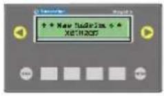 |
| XBT N400 | 4X20 matrix |  | ||
| XBT NU400 | - 24 V DC power supply- Preloaded application(1)- Point-to-point, multipoint mode link- Modbus master protocol- Backlit display in green | |||
| XBT N401 | - 24 V DC power supply- Point-to-point, multipoint, multidrop mode link- Protocols: Uni-Telway, Modbus master and slave- Indicator lights- Backlit display in green, orange or red- Printer link | 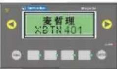 | ||
| XBT N410 | - 24 V DC power supply- Point-to-point, multipoint, multidrop mode link- Protocols: Uni-Telway, Modbus Master (and slave on the XBT N410(2) product)- Backlit display in green | 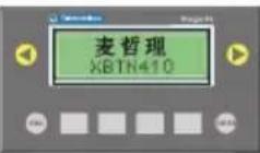 |
1. XBT N/XBT R display units
Overview of the XBT R range
| RANGE | CHARACTERISTICS | DISPLAY | MODE | FRONT PANEL |
| XBT R400 | - 5 V DC power supply via the PLC- Point-to-point mode link only- Protocols: Uni-Telway, Modbus master- Backlit display in green | 4X20 matrix | Input and Control | 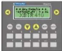 |
| XBT R410 | - 24 V DC power supply- Point-to-point, multipoint mode link- Protocols: Uni-Telway, Modbus master- Backlit display in green | |||
| XBT R411 | - 24 V DC power supply- Point-to-point, multipoint, multidrop mode link- Protocols: Uni-Telway, Modbus master and slave- Indicator lights- Backlit display in green, orange or red- Printer link | 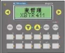 |
Point-to-point, multipoint, multidrop modes: see chapter B, section Control-system architectures, Page 15
Mode: see section Presentation of the commands, Page 8
1. XBT N/XBT R display units
Description
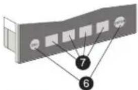
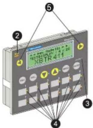
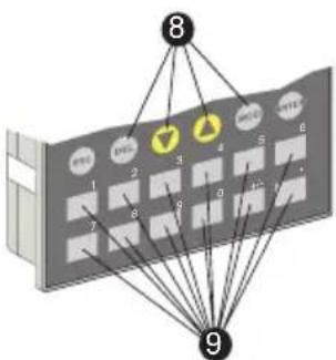
The display units include:
On the front panel
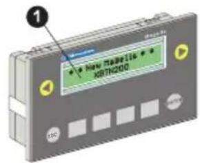
XBT-N200
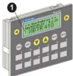
XBT R4..
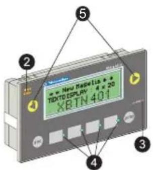
XBT-N401
flowchart
graph TD
    A["Component 1"] --> B["Component 2"]
    B --> C["Component 3"]
    C --> D["Component 4"]
    D --> E["Component 5"]
    E --> F["Component 6"]
    F --> G["Component 7"]
XBTN...
XBT R411
flowchart
graph TD
    A["Node 1"] --> B["Node 2"]
    B --> C["Node 3"]
    C --> D["Node 4"]
    D --> E["Node 5"]
    E --> F["Node 6"]
    F --> G["Node 7"]
    G --> H["Node 8"]
    H --> I["Node 9"]
    I --> J["Node 10"]
    style A fill:#f9f,stroke:#333
    style B fill:#f9f,stroke:#333
    style C fill:#f9f,stroke:#333
    style D fill:#f9f,stroke:#333
    style E fill:#f9f,stroke:#333
    style F fill:#f9f,stroke:#333
    style G fill:#f9f,stroke:#333
    style H fill:#f9f,stroke:#333
    style I fill:#f9f,stroke:#333
    style J fill:#f9f,stroke:#333
XBT R4..
1 - Backlit LCD screen
2 - Communication indicator light (XBT N401/R411)
3 - "Alarm" indicator light (XBT N401/R411)
4 - Indicator lights that can be controlled by the PLC (XBT N401/R411)
5 - Link or contextual control keys
6 - Service keys
7 - Function/service keys (according to XBT N configuration)
8 - Service keys (XBT R)
9 - Function keys (XBT R)
1. XBT N/XBT R display units
On the rear panel

natural_image
Technical diagram of a mechanical component with internal channels and a numbered label (10), no readable text or symbols present.XBT N200/400 XBT R400
XBT N410/NU400
XBT R410

natural_image
Diagram of an electronic device rear panel showing internal components and a green indicator light (no text or symbols)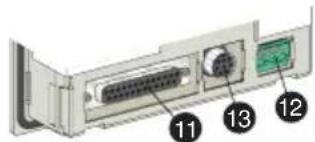
XBT N401 XBT R411
10 - RJ45: Serial link + PLC power supply
11 - SubD25 serial link
12 - 3-wire terminal block for 24 V DC power supply
13 - MiniDIN connector for printer
Presentation of the commands
The front panels of the display units feature function keys and/or service keys.
XBT R display units feature both types, whereas on the XBT N display units it depends on whether they have been customized for “control” mode or “input” mode.
The display units have the following user interface:
- XBT N:
- 4 customizable service keys (input mode), which can be configured as function keys (control mode)
- 2 non-configurable service keys
- 2 link or contextual control keys
- XBT R:
- 4 service keys
- 12 customizable function keys
- 2 non-configurable service keys
- 2 link or contextual control keys
1. XBT N/XBT R display units
XBT N display-unit commands
Control mode
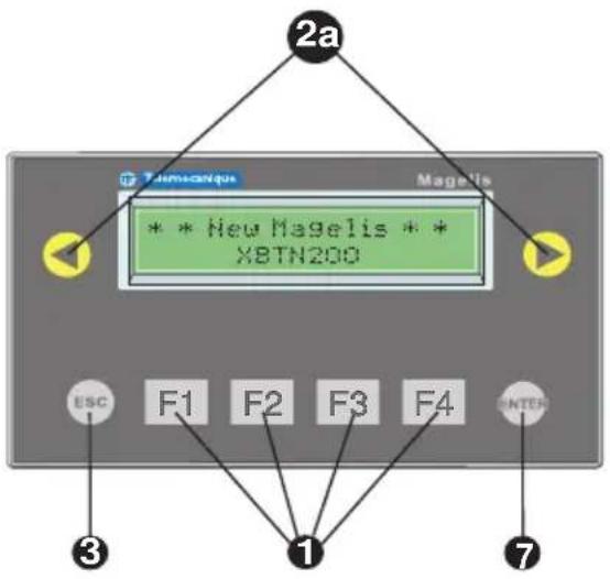
Input mode

1 Static function keys:
- Access to a page
- Impulse command
- Toggle command
2a Control mode:
Link or contextual control keys:
- Change page in a menu
- Display current alarms
-
Activate the function associated with a functional link:
-
Impulse command
- Toggle command
- Variable write operation
2b Input mode:
Link or contextual control keys:
- Change page in a menu
- Display current alarms
- Change digit in a variable field during input
-
Activate the function associated with a functional link:
-
Impulse command
- Toggle command
- Variable write operation
3 Service keys
- Cancel an entry or an action
- Return to the previous page
4 - Clear the selected digit or field
5 - Go up, go down in a page (XBT N40• and NU400)
- Increment/decrement the selected digit
- Select a value in a selection list
- Increment, decrement the value of a variable field
6 - Select a field
- Go to the next field
7 - Confirm a selection or an entry
- Acknowledge an alarm
1. XBT N/XBT R display units
XBT R display-unit commands
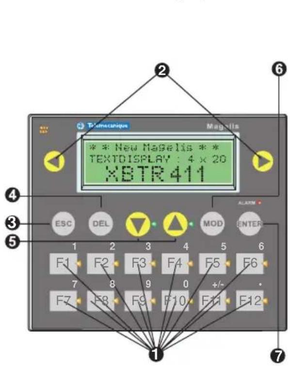
1 Dual-label keys (function/numeric):
- Access to a page
- Impulse command
- Toggle command
- Modification of a value
2 Link or contextual control keys:
- Change page in a menu
- Display current alarms
- Change digit in a variable field during input
-
Activate the function associated with a functional link:
-
Impulse command
- Toggle command
- Variable write operation
3 Service keys
- Cancel an entry or an action
- Return to the previous page
4 - Clear the selected digit or field
5 - Go up, down within a page
- Increment/decrement the selected digit
- Select a value in a selection list
- Increment, decrement the value of a variable field
6 - Select a field
- Go to the next field
7 - Confirm a selection or an entry
- Acknowledge an alarm
1. XBT N/XBT R display units

Connection
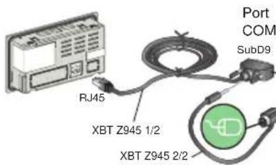
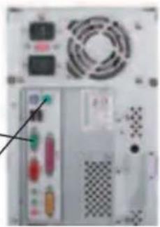
Magelis-PC link: Application transfer
Power supply mode: Powered by the PLC
XBT N200/N400 XBT R400
+ PC
Connection via an XBT Z945 cable
natural_image
Back view of a computer power drive unit with buttons and ventilation fan (no visible text or labels)Connection via a USB cable

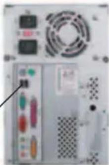
natural_image
Front view of a computer power drive unit with fan, buttons, and ventilation grille (no visible text or labels)Power supply mode: 24 V DC external power supply
Connection via an XBT Z915 cable
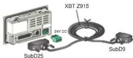
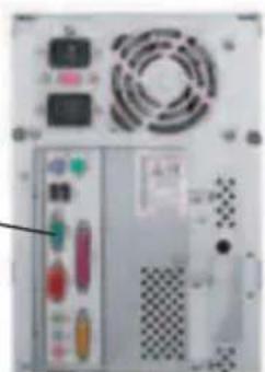
natural_image
Front view of a computer power supply unit with buttons, fans, and ventilation (no visible text or labels)XBT N410/N401 NU400
XBT R410/R411
+ PC
Connection via a USB cable
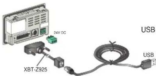

natural_image
Front view of a computer power supply unit with buttons and ventilation fan (no visible text or labels)Magelis-PLC link: Running
Power supply mode: powered by the PLC
XBT N200/N400
XBT R400
Twido/Micro
Premium/Nano
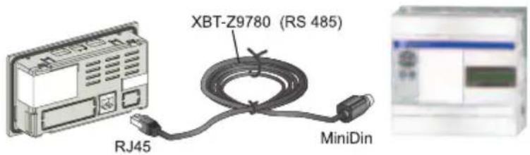
Depending on which protocol is used, if "?????" is displayed rather than any values, or the connection popup remains on screen, this indicates a communication problem. This may originate from the cable being used. To resolve this problem, use the XBT Z9780 cable fitted with the XBT ZN999 adaptor (for more information, see chapter E, section 1. Troubleshooting/Problems and solutions, Page 5).
RJ45 connector compatibility table
| XBT front panel Cable | |
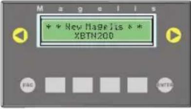 Without the Telemecanique logo Without the Telemecanique logo | XBT L1000 version ≤ V4.30 + XBT Z978 cable |
| XBT L1000 version ≥ V4.40 + XBT Z9780 cable + XBT ZN999 adaptor | |
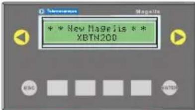 With the Telemecanique logo With the Telemecanique logo | XBT L1000 version ≥ V4.40 + XBT Z9780 cable |
Power supply mode: 24 V DC external power supply
XBT N410/NU400
XBT R410
Tesys Model U Altivar
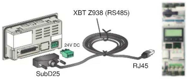
Power supply mode: 24 V DC external power supply
XBT-N401
XBT R410/R411
TSX 17/TSX series 7/
Twido/Micro/
Premium/Nano/Quantum/
Momentum/SCA62
(multipoint/multidrop)
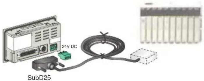
| PLC Cable | |
| Advantys XBT Z988 (RS232) | |
| LU9 GC3 XBT Z938 (RS485) | |
| Momentum XBT Z9711 (RS/232C) | |
| Quantum/984 XBT Z9710 (RS/232C) | |
| Twido/Micro/Premium/Nano XBT Z968/Z9680 (RS/485) (1)(2) | |
| SCA62 (multipoint) XBT Z908 (RS/485) (3) | |
| SCA64 XBT Z908 (RS485) | |
| TSX17 XBT Z958/Z928 (RS/485) | |
| TSX47/67/87 XBT Z948 (RS/485) | |
(1) XBT Z968: Straight-through cable / XBT-Z9680: Angled cable
(2) Modbus Master only
(3) Modbus Slave only
1. XBT N/XBT R display units
Magelis-printer link
XBT N401/R411
Printer
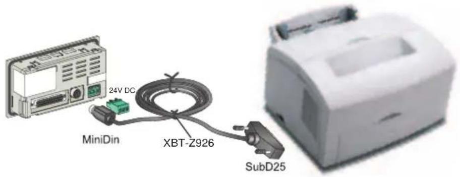
1. XBT N/XBT R display units

Characteristics
| Type of display unit | XBT-N200 | XBT-N400 | XBT NU400 | XBT-N401 | |
| Environment | |||||
| Conformity to standards IEC 61131-2, | IEC 60068-2-6, IEC 60068-2-27, UL 508, CSA C22-2 no. 14 | ||||
| Product certification CE, UL, CSA, Class 1 Div 2 T5 (UL and CSA) | |||||
| Temperature Operation 0 ... +55°C (32°F ... 131°F) | |||||
| Storage -20 ... +60°C (-4°F ... 140°F) | |||||
| Relative humidity 0 ... 85% (without condensation) | |||||
| Degree of protection | Front panel IP 65, according to IEC 60529, UL Type 4, 4X | ||||
| Rear panel IP 20, according to IEC 60529 | |||||
| Shock resistance According to IEC 60068-2-27; semi-sinusoidal impulse 11 ms, 15 g on 3 axes | |||||
| Vibrations | According to IEC 60068-2-6, 10 to 57 Hz at 0.075 mm; 57 to 150 Hz 1 g for 3 hours per axis | ||||
| E.S.D. According to IEC 61000-4-2, level 3 | |||||
| Electromagnetic interference According to IEC 61000-4-3, 10 V/m | |||||
| Electrical interference | According to IEC 61000-4-4, level 3 | ||||
| Mechanical characteristics | ||
| Mounting and fixing | Flush-mounted, fixed by 2 spring clips supplied pressure-mounted for panels 1.5 to 6 mm thick | |
| Material | Screen protection | Polyester |
| Front frame Polycarbonate/polybutylene terephthalate alloy | ||
| Keypad | UV autotex polyester | |
| Electrical characteristics | |||
| Power supply | Voltage | 5 V DC via the serial link with the PLC | 24 V DC (200 mA max) |
| Voltage limits | 18 . . . 30 V DC | ||
| Ripple factor | 5% maximum | ||
| Operating characteristics | |||||
| Display unit | Type | Backlit LCD | |||
| Capacity | 2 x 20 characters | From 4 x 20 to 1 x 5 characters (large size) | |||
| Signaling | No LEDs | 6 LEDs | |||
| Dialog application | No. of pages | 128 | 200 | ||
| Transmission medium (asynchronous serial link) | RS232/RS485 | ||||
| Downloadable protocols | Modbus master, Uni-Telway Modbus master | Modbus master and slave, Uni-Telway | |||
| Real-time clock | Access to the PLC real-time clock | ||||
| Connection | Power supply | Via the PLC link cable | Removable terminal block3 screw terminals (pitch 5.08)Clamping capacity: 1.5 mm2 | ||
| Serial link | RJ45 female connector (RS232/RS485) | 25-pin female SubD connector | |||
| Printer link | No printer link | MiniDin | |||
1. XBT N/XBT R display units
| Type of display unit | XBT N410 | XBT R400 | XBT R410 | XBT R411 | |
| Environment | |||||
| Conformity to standards IEC 61131-2, | IEC 60068-2-6, IEC 60068-2-27, UL 508, CSA C22-2 no. 14 | ||||
| Product certification CE, UL, CSA, Class 1 Div 2 T5 (UL and CSA) | |||||
| Temperature Operation 0 ... +55°C (32°F ... 131°F) | |||||
| Storage -20 ... +60 °C (-4 °F ... 140 °F) | |||||
| Relative humidity 0 ... 85% (without condensation) | |||||
| Degree of protection | Front panel IP 65, according to IEC 60529, UL Type 4, 4X | ||||
| Rear panel IP 20, according to IEC 60529 | |||||
| Shock resistance According to IEC 60068-2-27; semi-sinusoidal impulse 11 ms, 15g on 3 axes | |||||
| Vibrations | According to IEC 60068-2-6, 10 to 57 Hz at 0.075 mm; 57 to 150 Hz 1 g for 3 hours per axis | ||||
| E.S.D. According to IEC 61000-4-2, level 3 | |||||
| Electromagnetic interference According to IEC 61000-4-3, 10 V/m | |||||
| Electrical interference According to IEC 61000-4-4, level 3 | |||||
| Mechanical characteristics | ||
| Mounting and fixing | Flush-mounted, fixed by 2 spring clips supplied pressure-mounted for panels 1.5 to 6 mm thick | |
| Material Screen | protection Polyester | |
| Front frame Polycarbonate/polybutylene terephthalate alloy | ||
| Keypad | UV autotex polyester | |
| Electrical characteristics | ||||
| Power supply | Voltage | 24 V DC (200 mA max) | 5 V DC via the serial link with the PLC | 24 V DC (200 mA max) |
| Voltage limits | 18 . . . 30 V DC | |||
| Ripple factor | 5% maximum | |||
| Operating characteristics | |||||
| Display unit | Type | Backlit LCD | |||
| Capacity | From 4 x 20 to 1 x 5 characters (large size) | ||||
| Signaling | No LEDs | 16 LEDs | |||
| Dialog application | No. of pages | 200 | |||
| Transmission medium (asynchronous serial link) | RS232/RS485 | ||||
| Downloadable protocols | Modbus master (and slave on the XBT N410(2) product), Uni-Telway | Modbus master, Uni-Telway | Modbus master and slave, Uni-Telway | ||
| Real-time clock | Access to the PLC real-time clock | ||||
| Connection | Power supply | Removable terminal block3 screw terminals (pitch 5.08)Clamping capacity: 1.5 mm2 | |||
| Serial link | 25-pin female SubD connector | RJ45 female connector(RS232/RS485) | 25-pin female SubD connector | ||
| Printer link | No printer link | MiniDin | |||
1. XBT N/XBT R display units
| Display units | Display unit with alphanumeric screen | Display units with matrix screen | ||
 |  | 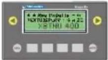 | 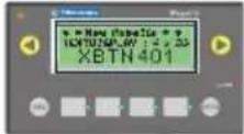 | |
| Display unit references XBT-N200 XBT-N400 XBT NU400 XBT-N401 |
| Display | |||
| Type Backlit LCD Backlit | LCD 122 x 32 pixels | ||
| Color Green Green/Orange/Red | |||
| Capacity | 2 lines of 20 characters | 1 to 4 lines of 5 to 20 characters | |
| Active screen area 74 x | 12 mm 72 x 20 mm | ||
| Size of characters 5.55 x | 3.2 mm 4.34 x 2.95 to 17.36 x 11.8 mm | ||
| Keypad 8 keys, 4 of which can be re-labeled | ||
| Signaling No LEDs | 6 LEDs including 4 for the 4 central keys | |
| Functions | ||
| Number of pages (maximum) | 128 application pages | 200 application pages256 alarm pages |
| Variables per page 8 | 40 | |
| Vertical page scrolling | no | yes |
| Number of lines per page | 2 | 25 |
| Representation of variables | Alphanumeric | |
| Fonts | Latin + Katakana | Latin + Cyrillic + Katakana + Greek + Simplified Chinese |
| Languages | Number of languages only limited by the size of the memory | |
| Communication | ||||
| Serial link | RS232 C, RS485 | |||
| Protocols Modbus master | Uni-Telway | Modbus master | Modbus master and slave, Uni-Telway | |
| Programming software | XBTL1001M, XBTL1003M (using Windows 98SE, 2000 or XP) |
1. XBT N/XBT R display units
| Display units Display units with matrix screen | ||||
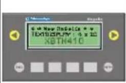 | 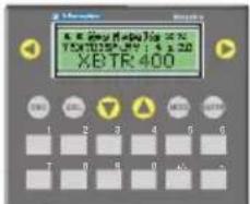 |  |  | |
| Display unit references XBT | N410 | XBT R400 | XBT R410 | XBT R411 |
| Display | ||
| Type Backlit LCD 122 x 32 pixels | ||
| Color Green Green/Orange/Red | ||
| Capacity 1 to 4 lines of 5 to 20 characters | ||
| Active screen area 72 x 20 mm | ||
| Size of characters 4.34 x 2.95 to 17.36 x 11.8 mm | ||
| Keypad | 8 keys, 4 of which can be re-labeled | 20 keys, 12 of which can be re-labeled | |
| Signaling No LEDs | 16 LEDs including 14 for the central keys | ||
| Functions | |
| Number of pages (maximum) | 200 application pages256 alarm pages |
| Variables per page 40 | |
| Vertical page scrolling yes | |
| Number of lines per page | 25 |
| Representation of variables | Alphanumeric |
| Fonts Latin + Cyrillic + Katakana + Greek + Simplified Chinese | |
| Languages | Number of languages only limited by the size of the memory |
| Communication | |||
| Serial link | RS232 C, RS485 | ||
| Protocols | Modbus master (and slave on the XBT N410(2) product), Uni-Telway | Modbus master, Uni-Telway | Modbus master and slave, Uni-Telway |
| Programming software | XBTL1001M, XBTL1003M (using Windows 98SE, 2000 or XP) |
2. The XBT L100• program
Presentation
XBT L100• is the configuration software for the Magelis range of operator terminals.
This software runs on computers using Windows 98SE, 2000 and XP operating systems.
Installation
In order to use XBT L100• software, the following minimum configuration is required:
- PC Pentium II 350 MHz
- 4x CD-ROM minimum
- Microsoft 98SE, 2000 or XP
-128 MB RAM - 30 MB of space available on the hard disk
- SVGA video card or better
- Mouse or compatible pointing device
To install the XBT L100• software, insert the CD-ROM in the CD-ROM drive and follow the on-screen instructions.
If the installation program does not run automatically, select Run from the Start menu. Then, type "D:\SETUP.EXE" (where D: is your CD-ROM drive) and press Enter. During installation, you will be asked which protocols and components you wish to install.
Installation of the Xway driver is launched automatically after installation of XBT L100•. This driver is used to transfer applications between the PC and the display unit.
Once installed, this driver can be configured from the Windows control panel.
The USB drivers are not installed automatically, but are included on the XBT-L100• installation CD-ROM. These drivers are requested automatically by Windows when the USB cable is connected to the PC.
They can also be installed by connecting the USB cable.

Functions
The XBT L100• configuration software is used to create applications that can be used by Magelis display units, in which it will be possible to:
- Create different types of page:
- application pages
- alarm pages
These pages can contain all sorts of variables predefined in XBT L100•. Different properties can be assigned to them.
- Configure function keys to perform commands on the machine, or call up application pages
- Import the list of PL7 (Junior/Micro/Pro), Concept and Twidosoft type PLC symbols, to avoid double entry of variables
XBT L100• also supports the monitoring of applications created with the software in the design office, without using a display unit or a PLC.
The simulation program is used in conjunction with the computer keys to test:
- Navigation between pages
- Entering variables
- Displaying variables
- Managing alarms
- Etc.
B
Chapter B
Using the
XBT N/XBT R display units
Basic principle of human-machine dialog. What is a display unit for?
- Introduction: Display unit operating concepts 5
HMI 5
Dialog between the PLC and the display unit 8
Operating modes 9
Organization of Magelis functions 14
Control-system architectures 15
Principle of application pages 17
Principle of system pages 17
Principle of alarm pages 18
Display unit self-tests 23
- Keys and indicator lights 24
Key functions 24
Indicator-light functions (XBT N401/R411) 26
- Sending commands to the control system 27
Types of command 27
Commands sent via function keys 28
Commands sent via functional links 29
- Application pages ____ 31
Display of an application page 31
Scrolling within a page 33
- Alphanumeric fields 35
Input/Modification of a value 35
Exit input on time out 38
Input report 38
- System pages 39
Display from an application page 39
Display from the dialog table 39
- Alarm pages 40
Alarm displays 40
Alarm log 41
- Printing 43
Principles 43
Print alarms as a data stream 43
Print the alarm log 43
Print the list of current alarms 44
Stop printing 45
Contents
- Setting the display unit parameters 46
Application language 46
Date and time 47
Product references 48
Line parameters 49
1. Introduction: Display unit operating concepts

HMI
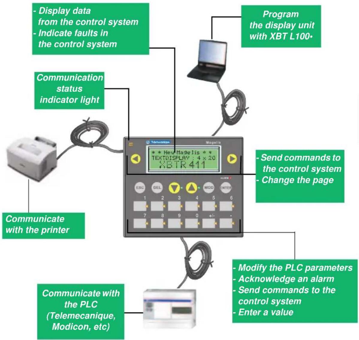
flowchart
graph TD
    A["Program the display unit with XBT L100"] --> B["Display data from the control system"]
    B --> C["Indicate faults in the control system"]
    C --> D["Communication status indicator light"]
    D --> E["Communicate with the printer"]
    E --> F["Communicate with the PLC (Telemecanique, Modicon, etc)"]
    F --> G["Send commands to the control system"]
    G --> H["Change the page"]
    H --> I["Modify the PLC parameters"]
    I --> J["Acknowledge an alarm"]
    J --> K["Send commands to the control system"]
    K --> L["Enter a value"]
For XBT N display units, depending on the mode chosen, the keypad will either be in control mode or in input mode (see chapter A, section Presentation of the commands, Page 8). The button labels are therefore interchangeable.
| XBT ref. Note | |
| N200/N400/N410NU400R400/R410 | No indicator lights |
| No printer link |
1. Introduction: Display unit operating concepts
Applications created in XBT L100• can be associated with:
- Production monitoring
- Preventive maintenance
- Corrective maintenance
- Process control
Production monitoring
Display process status messages:

Automatic operation Start motor End of lift Rotation of grip
■ Preventive maintenance

Counting parts for production monitoring:
Housing: 7555 Unit: 1200
■ Corrective maintenance

Indication of process faults:
Oil level low Door open
| XBT ref. Note | |
| / | / |
1. Introduction: Display unit operating concepts
■ Process control

Process control via configurable function keys:
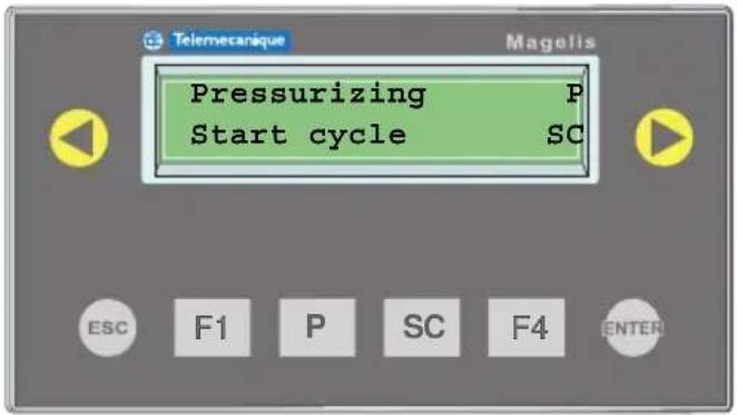
As indicated on the display-unit screen, pressurizing is monitored by the P button and start cycle by the SC button.
| XBT ref. Note | |
| N200/N400/N401/N410 NU400 | For display units in "control" mode only |
1. Introduction: Display unit operating concepts
Dialog between the PLC and the display unit
Human/machine dialog between the Magelis display unit and the PLC consists of an exchange of data between the 2 devices.
Various types of data can be exchanged.

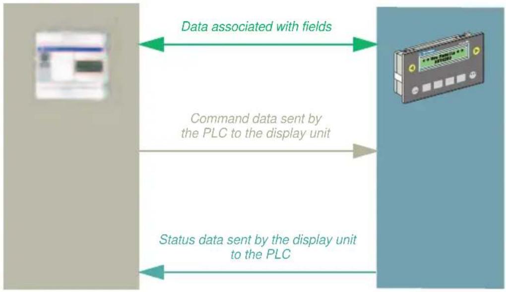
flowchart
graph LR
    A["Data associated with fields"] --> B["Command data sent by the PLC to the display unit"]
    B --> C["Status data sent by the display unit to the PLC"]
WARNING
LOSS OF CONTROL
- Loss of communication between the display unit and the PLC can result in partial or complete loss of control of the machine.
- Check the display-unit connection by monitoring the "Communication monitoring" word in the dialog table via the PLC program.
Failure to follow this instruction can result in death, serious injury, or equipment damage.
For more information, see chapter C, section 4. Dialog table, Page 53
| XBT ref. Note | |
| / | / |
1. Introduction: Display unit operating concepts

Operating modes
Magelis display units have 2 exclusive operating modes:
- Transfer mode enabling dialog applications to be transferred between the XBT L100• program and the Magelis display unit.
- Run mode enabling exchanges between the display unit and the control system (controlling the latter).
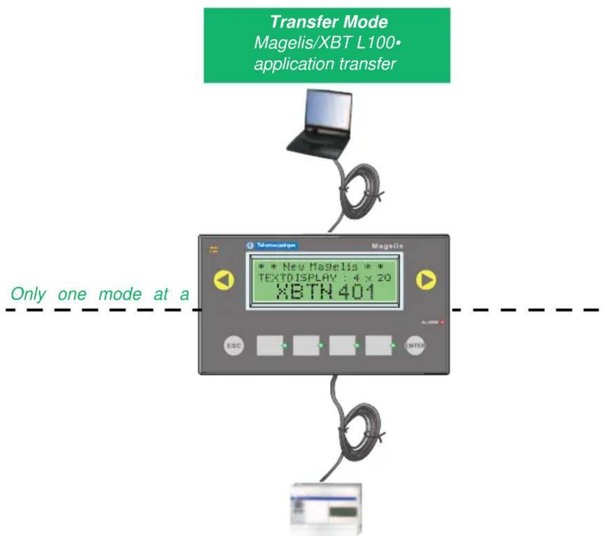
flowchart
graph TD
    A["Transfer Mode\nMagelis/XBT L100\napplication transfer"] --> B["Device Display"]
    B --> C["Only one mode at a"]
    C --> D["Image Box"]
Run Mode Dialog with the control system
| XBT ref. Note | |
| / | / |
1. Introduction: Display unit operating concepts
On power-up, the display unit automatically detects the exchange mode (only one mode at a time) depending on the equipment connected on its serial link.
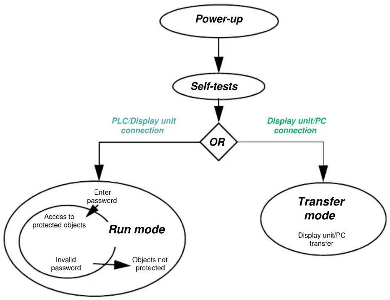
flowchart
graph TD
    A["Power-up"] --> B["Self-tests"]
    B --> C{OR}
    C -->|PLC/Display unit connection| D["Enter password"]
    C -->|Display unit/PC connection| E["Transfer mode"]
    D --> F["Access to protected objects"]
    D --> G["Invalid password"]
    F --> H["Run mode"]
    G --> I["Objects not protected"]
    E --> J["Display unit/PC transfer"]
Transfer mode
This is the mode in which the display unit communicates with the XBT L100• configuration software. It is used to transfer the application in both directions.
| XBT ref. Note | |
| / | / |
1. Introduction: Display unit operating concepts
Connecting the PC and the display unit using the communication cable is sufficient to switch the display unit to transfer mode. No other operator action on the display unit is necessary in this mode.
Export: Loading the human/machine dialog application and the control system link protocol into the display unit.
E.g.: XBT-N401
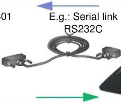
E.g.: Serial link RS232C
PC with XBT L100•
Import: Transfer of an application from the display unit to the PC.
Cable connection
see chapter A, section Connection, Page 11
Procedure with XBT L100•
Select the Transfer/Export (or Transfer/Import) menu.
Communication indicator light

- Indicator light off: No cable or communication
- Indicator light blinking: Exchanges between the PC and the display unit
| XBT ref. Note | |
| N200/N400/N410NU400R400/R410 | No indicator lights |
1. Introduction: Display unit operating concepts
Run mode
Run mode is used to control the control system:
- Page display
- Input/Modification of control-system architecture parameter values
- Process control (discrete)
- Viewing and acknowledgment of alarms

Example: Display of an application page
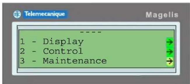



Go to the desired page
Access the page
The operator presses the

key to access the desired page.
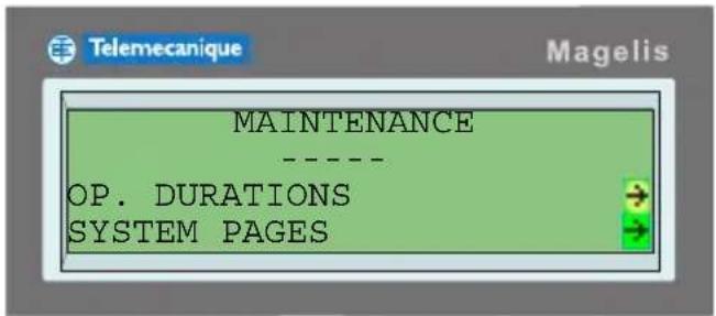
(For more information about how system pages are displayed, see section "6. System pages", Page 39.)
| XBT ref. Note | |
| N200 No management of alarms. No access to the "Menu" page | |
| N400/N410NU400 | No access to the "Menu" page in "control" mode |
1. Introduction: Display unit operating concepts
Protection
To ensure only authorized persons are able to read and write data, it is possible to protect:
- Access to pages
- Modification of fields
- Control via functional links
If an operator does not have authorization:
- Protected pages no longer appear in the list of pages
- Protected fields behave as if they had been configured as read-only
The password is entered via the "Password" system page. A navigation link to the "Password" system page is required on one of the application pages. (For more information about how system pages are displayed, see section "6. System pages", Page 39).
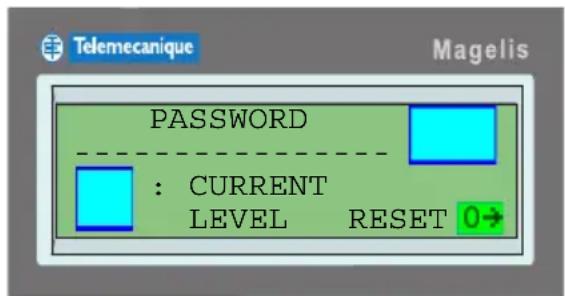
There are three access levels: A, B and C.
These passwords are defined in XBT L100•. A password consists of four alphanumeric characters (default value 1111).
WARNING
UNAUTHORIZED ACCESS
A display unit must only be installed and used by authorized personnel.
Failure to follow this instruction can result in death, serious injury, or equipment damage.
| XBT ref. Note | |
| N200 No access | to the password page |
| N400/N410NU400 | No access to the password page in “control” mode |
1. Introduction: Display unit operating concepts

Organization of Magelis functions
Magelis (or XBT) display units have a certain number of functions. The flowchart below shows these different functions.
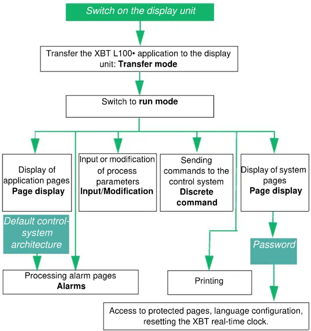
flowchart
graph TD
    A["Switch on the display unit"] --> B["Transfer the XBT L100• application to the display unit: Transfer mode"]
    B --> C["Switch to run mode"]
    C --> D["Display of application pages Page display"]
    C --> E["Input or modification of process parameters Input/Modification"]
    C --> F["Sending commands to the control system Discrete command"]
    C --> G["Display of system pages Page display"]
    D --> H["Default control-system architecture"]
    H --> I["Processing alarm pages Alarms"]
    E --> J["Printing"]
    G --> K["Password"]
    I --> L["Access to protected pages, language configuration, resetting the XBT real-time clock."]
| XBT ref. Note | |
| N200 No alarm management | |
| N200/N400/N410NU400R400/R410 | No printer link |
1. Introduction: Display unit operating concepts
Control-system architectures
Protocols
Communication between the display unit and connected equipment is achieved by means of a communication protocol, which is selected when creating the application in XBT L100•.
The protocols available for the range support communication with the Schneider range of PLCs, specific equipment (speed drives), etc.
These protocols are Uni-Telway and Modbus (master and slave).
There are several types of architecture, which enable one display unit to be linked to several devices or several display units to one device.
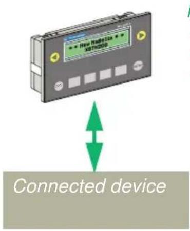
Point-to-point connection
One display unit linked to one device.
Modbus, Uni-Telway protocols:
- Modbus master
- Uni-Telway slave
- Modbus slave
| XBT ref. Note | |
| N200/N400 In Uni-Telway, a slave number has a fixed value of 4 | |
| NU400 Modbus master protocol only | |
| N200/N400/N410(1)R400/R410 | Not compatible with the Modbus slave protocol |
1. Introduction: Display unit operating concepts
■ Multipoint connection (XBT N401/N410/NU400/R410/R411)
One display unit linked to several devices (maximum of 15)
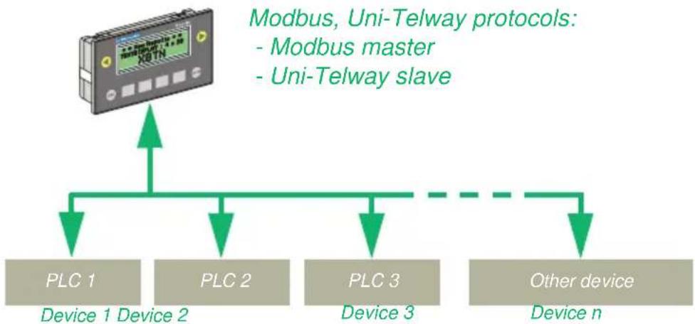
flowchart
graph TD
    A["Modbus, Uni-Telway protocols: - Modbus master - Uni-Telway slave"] --> B["Device 1"]
    A --> C["Device 2"]
    A --> D["Device 3"]
    A --> E["Other device"]
    B --> F["Device 1 Device 2"]
    C --> G["Device 2"]
    D --> H["Device 3"]
    E --> I["Device n"]
■ Multidrop connection (XBT N401/N410/R410/R411)
Several display units linked to one device
Modbus, Uni-Telway protocols:
- Modbus slave
- Uni-Telway slave
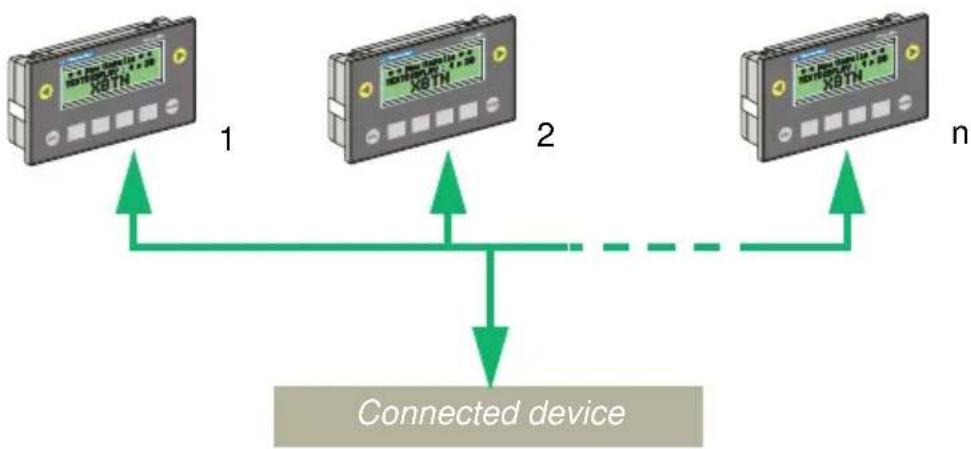
flowchart
graph TD
    A["Device 1: XBTN"] -->|Signal| B["Connected device"]
    C["Device 2: XBTN"] -->|Signal| B
    D["Device n: XBTN"] -->|Signal| B
    B -->|Output| E["Output"]
| XBT ref. Note | |
| N200/N400R400 | Point-to-point only |
| NU400 No multidrop connection | |
| NU400 Modbus master protocol only | |
| N200/N400/N410(1)R400/R410 | Not compatible with the Modbus slave protocol |
1. Introduction: Display unit operating concepts
■ Principle of application pages
Definition
Application pages are pages designed to provide information about the control-system architecture being run. They also serve to clarify any operation that the operator might have to perform in a given context.
Application pages can be interlinked to create authorized sequences during operation (see chapter C, section Functional links, Page 51).
Unauthorized operators can be prevented from displaying protected pages (see chapter C, section Protecting a page, Page 28)
■ Principle of system pages
Definition
System pages are predefined pages, which are used to perform operations relating to the display unit "system".
In run mode, these pages can be accessed in the same way as application pages.
System pages are pages processed as if they were application type pages. Hence they are stored with the application pages in the developed application file.
There are 3 types of system page:
- Standard system pages, which can be called by accessing an application page (numbers 1 to 100)
- System pages, which cannot be called by accessing an application page (numbers 101 to 200)
- Popup/message system pages, which cannot be called (numbers 201 to 300)
| XBT ref. Note | |
| / | / |
1. Introduction: Display unit operating concepts
(For more information about how system pages are displayed, see section "6. System pages", Page 39.)
The advantage of being able to view these pages with XBT L100• is that system messages can be translated or customized.
Principle of alarm pages
Objective
An alarm page has the same characteristics as an application page with respect to:
- The text
- The field
The advantage of an alarm page lies in its event-triggered display. Each alarm page has an associated dialog-table word bit (see chapter C, section 4. Dialog table, Page 53).
If the bit is at state 1, the page is displayed and the text blinks.


| XBT ref. Note | |
| N200 No alarm management | |
1. Introduction: Display unit operating concepts
Advantages in run mode
- When a fault appears, it is often the consequence of other faults. MAGELIS products, due to their priority system, can display the most important fault, i.e., that presenting the highest risk to the control-system architecture.
- All faults are time-stamped on appearance.
The actual display of an alarm depends on the priority it has been allocated (see section "Display priority", Page 19).
Alarms pending on the control-system architecture are stored in an "Alarm list".
ALARM
- The "Alarm" indicator light continuously informs the operator about the state of the alarm list:
- Off: The alarm list is empty.
- Blinking: The alarm list contains alarms, which have appeared since the alarm list was viewed (new alarms).
- On: The alarm list contains alarms, which occurred before the alarm list was viewed (alarms already displayed).
■ Display priority
A priority can be associated with each alarm page. An alarm page has priority over an application page and a system page. An alarm page does not have priority over a value, which is currently being entered.
Different alarm pages may have different priorities. There are 16 possible levels of priority (the lowest display priority being priority no. 16).
| XBT ref. Note | |
| N200 No alarm management | |
| N200/N400/N410NU400R400/R410 | No indicator lights |
1. Introduction: Display unit operating concepts
Exception for priority 0
If priority 0 is allocated to an alarm page, when the alarm appears on the control-system architecture:
- The alarm page is not displayed, but stored in the alarm list, thus the current display will not be disturbed.
- The alarm indicator light blinks to signal the alarm.
When an alarm is activated, it is stored in the alarm list by the display unit.
Appearance types
There are several types of appearance for an alarm page.
Alarm pages can be:
- Displayed directly on the screen
- Printed directly (data-stream printing) ^(1)
- Stored in the list of current alarms
For more information, see chapter C, section Page appearance types, Page 30.
■ Storage principle in the alarm list
If the alarms have equal priority, they are stored from the oldest to the most recent.
If the display unit is available (i.e., not occupied by a higher-priority display), the oldest alarm is displayed. In a control system it is often the oldest alarm, which is the most interesting, as the more recent alarms are often a consequence of the fault signaled by the first alarm (classic case of bursts of alarms).
If higher-priority alarms appear:
- They are stored at the top of the list.
- If the display unit is available (i.e., not occupied by a higher-priority display), the highest priority new alarm is displayed.
| XBT ref. Note | |
| N200 No alarm management | |
| N200/N400/N410NU400R400/R410 | (1) No printer link |
1. Introduction: Display unit operating concepts
Acknowledgment of alarms
When designing pages, it is possible to define whether the alarm page should be acknowledged systematically by the operator or not (obligatory acknowledgment).

The alarm page is acknowledged on the display by pressing ENTER. The alarm message changes to a steady display.
Depending on the choice made, management of these 2 types of alarm is as follows:
1 - Alarms, which must be acknowledged (obligatory)
An alarm, which must be acknowledged, remains in the alarm list until it is acknowledged by the operator, even if the cause of the fault has disappeared.
Advantage: Picks up transient faults (instability of a discrete sensor, for example).
2 – Alarms, which can be acknowledged but do not have to be
An alarm, which can be acknowledged but does not have to be, disappears from the alarm list as soon as the cause of the fault has disappeared, regardless of whether or not it has been acknowledged by the operator.
Advantage: The display unit is not monopolized by displays of faults considered of minor importance to the application.
Alarm log
The display units can manage a log of the alarm pages. They store the alarm pages with the text, but without variable values (for more information, see section Alarm log, Page 41).
| XBT ref. Note | |
| N200 No alarm management | |
1. Introduction: Display unit operating concepts
■ Display principle of alarm pages
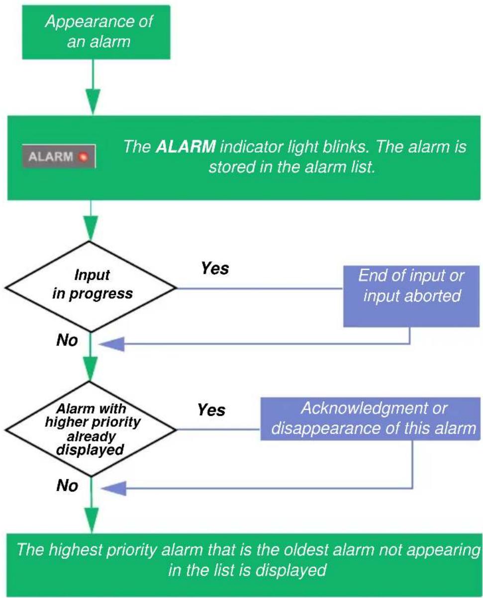
flowchart
graph TD
    A["Appearance of an alarm"] --> B["The ALARM indicator light blinks. The alarm is stored in the alarm list."]
    B --> C{Input in progress}
    C -->|Yes| D["End of input or input aborted"]
    C -->|No| E{Alarm with higher priority already displayed}
    E -->|Yes| F["Acknowledgment or disappearance of this alarm"]
    E -->|No| G["The highest priority alarm that is the oldest alarm not appearing in the list is displayed"]
| XBT ref. Note | |
| N200 No alarm management | |
| N200/N400/N410NU400R400/R410 | No indicator lights |
1. Introduction: Display unit operating concepts
■ Display unit self-tests
■ Self-test on power-up
When the display unit is powered up, the following self-tests are performed:
| The working memory (RAM) | Writing/reading | Value read different from value written | Operation impossible: STOP |
| The firmware Checksum calculation and checking | Calculated checksum <> Stored checksum | Operation impossible: STOP | |
| The application memory | Checksum calculation and checking | Calculated checksum <> Stored checksum | Operation impossible: Transfer compulsory |
Continuous self-test
A continuous self-test checks that the program is operating correctly (watchdog).
NOTE: If a problem is detected, which prevents operation of the product, the display unit turns off all its indicator lights, stops working and displays an error number (if the detected fault permits it to do so). If the same problem appears after the display unit is switched back on, inform the maintenance department of this error number.
XBT ref. Note
/
/
2. Keys and indicator lights

Key functions
| Key Key function | |
 | - Enter a page number, a password or a variable-field value.- Select a field or go to the next field each time MOD is pressed (left to right and top to bottom). |
 | - Exit the alarm display- Return to the previous page (1)- Exit an input without acceptance of the value entered |
  | - Change page in a menu- Display current alarms- Change digit in a variable field during input- Activate the function associated with a functional link:- impulse command- toggle command- writing variables |
  | - Go up/down within a page- Increment/decrement the selected digit- Increment/decrement the value of a variable field- Select a value in a selection list |
 | - Delete the selected digit or field |
 | - Confirm a selection- Confirm an input- Acknowledge an alarm |
 =1 =1 | - Access a page- Execute an impulse command- Execute a “toggle” command- Modify a value (XBT R4•• only) |
| XBT ref. Note | |
| / | / |
(1): Only the last 16 pages are memorized.
2. Keys and indicator lights
Exception for XBT R display units:
Keys F1 to F12 are dual-label Fx/Nx (function/numeric) keys. They can act as both function keys and input keys.
They operate as follows:
- If the user is not modifying a value, the keys act as function keys.
- If the user is modifying the value of a field, the keys automatically act as input keys.
NOTE: It is impossible to enter a value if a function key has been pressed, in the same way that it is impossible to leave input mode if the value of a field is being modified.
| XBT ref. Note | |
| N200/N400/N401/N410NU400 | No dual labeling of keys |
2. Keys and indicator lights
Indicator-light functions (XBT N401/R411)
| Indicator light Color Status Meaning | |||
 (Communication) (Communication) | Amber | - Off | - No cable or no communication |
| - Blinking - C | Communication OK | ||
 (Alarms) (Alarms) | Red | Alarm list: | |
| - Off - Empty | |||
| - On - Alarms | already displayed | ||
| - Blinking - N | new alarms not previously displayed | ||
| Input mode | |||
 (Up/Down) (Up/Down) | Green | - Off | - Key inactive |
| - On | - Possibility of going up/down within a page | ||
| - Blinking | - Indicates the possibility:- Of selecting a value in a list- Of incrementing/decrementing the selected digit | ||
| Control mode | |||
 (Indicator light for static function keys) (Indicator light for static function keys) | Green(XBT N)Amber(XBT R) | - Off- On | These indicator lights are governed by the control system. Their state is determined entirely by the application program of the control system governing the display unit. As a result, their role can vary from application to application:- Signaling linked to the key (same type of role as the system LEDs above)- Signaling the status or a fault of the component governed by the key |
| XBT ref. Note | |
| N200/N400/N410NU400R400/R410 | No indicator lights |
3. Sending commands to the control system
Types of command
MAGELIS display units are used to send commands to the control system via function keys or functional links.
Impulse command
The control system is activated by pressing a function key (or functional link). If the key (or functional link) is released, the action stops.
Motor command

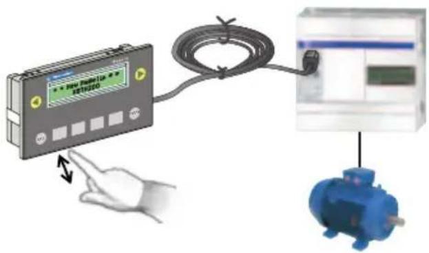
| Key Bit | |
| released 0 | |
| pressed 1 | |
| released 0 |
In the control system, the falling edge of the control bit should be monitored to control an action.
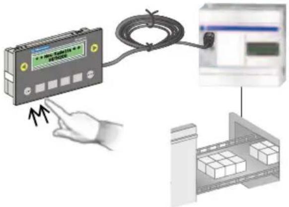
Toggle command
The control system is activated by pressing the function key (or functional link).. If the function key (or functional link) is pressed again, the action on the control system stops.
Conveyor forward command

| Key Bit | |
| released 0pressed 1released 1pressed 0 |
| XBT ref. Note | |
| / | / |
3. Sending commands to the control system
Commands sent via function keys

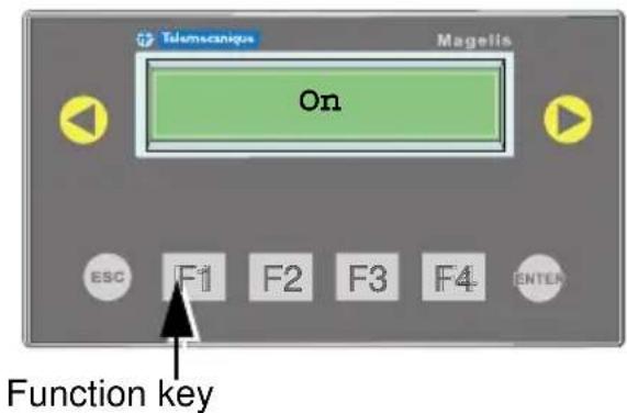
The dialog table (see chapter C, section 4. Dialog table, Page 53) enables dialog between the PLC and the display unit. In this table, one word is reserved to supply the PLC with the status of the function keys in the form of a word bit.
| Bit 15 to Bit 12 | Bit 11 | Bit 10 | Bit 9 | Bit 8 | Bit 7 | Bit 6 | Bit 5 | Bit 4 | Bit 3 | Bit 2 | Bit 1 | Bit 0 |
| R e | s | e r | v | e | d | F | 2 | F | 1 | 1 | F | 0 |

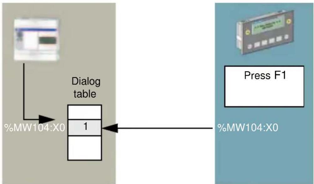
flowchart
graph LR
    A["User"] --> B["Dialog table"]
    B --> C["1"]
    D["Press F1"] --> E["%MW104:X0"]
    style A fill:#f9f,stroke:#333
    style D fill:#bbf,stroke:#333
| XBT ref. Note | |
| N200/N400/N401/N410NU400 | For display units in "control" mode only |
3. Sending commands to the control system
The display unit writes to the PLC dialog table.
NOTE: Pressing both function keys simultaneously triggers both functions.
Commands sent via functional links
Functional links are used to create additional control functions. To do this, the operator uses the and keys located on each side of the screen.
The application designer can therefore give the operator the option of sending commands to equipment from the application page.
Commands may be one of two types:
- Impulse
- Toggle
Functional command link

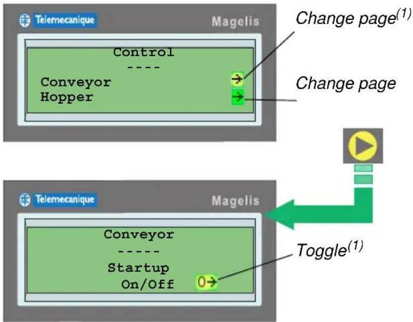
| XBT ref. Note | |
| / | / |
(1): Link blinking to indicate that it is active
3. Sending commands to the control system
■ Representation of command links

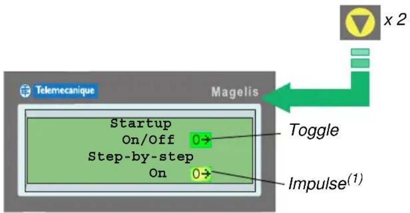
0 = Bit variable associated with link equals 0 1 = Bit variable associated with link equals 1

The operator controls the conveyor step-by-step. When he releases the button, the conveyor stops.
| XBT ref. Note | |
| N200 No scrolling | |
| N400/N401/N410NU400 | For display units in “input” mode only |
(1): Link blinking to signal that the link is active
4. Application pages
These pages are configured and developed by the application designer in XBT L100•.
They are used to display all the information required to control the equipment connected to the display unit.
■ Display of an application page
On power-up (default page)
When designing the application in XBT L100•, the operator can select a default page.
When the display unit is powered up, this is the first page to be displayed.
Via function keys
It is possible to display a page directly by pressing a function key.

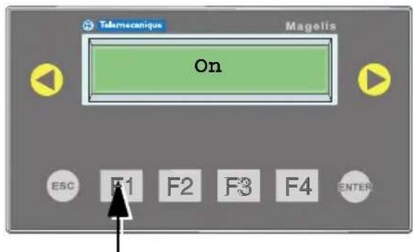
Function key

WARNING
IMPROPER OPERATION
Do not use a function key to start an operation, which may be potentially dangerous to an inexperienced user.
Failure to follow this instruction can result in death, serious injury, or equipment damage.
| XBT ref. Note | |
| N200/N400/N401/N410NU400 | For display units in "control" mode only |
4. Application pages
Via a navigation link
As with function keys, it is possible to reach a page directly via navigation links.

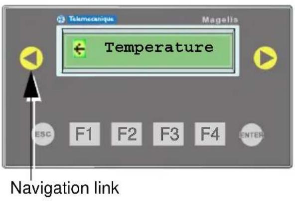
Via the PLC
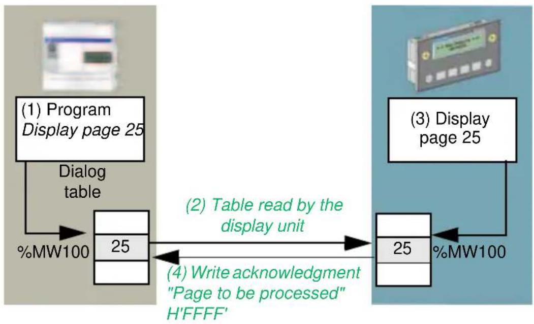
The display is the result of a word in the dialog table in which the program has written the number of the page to be processed (see chapter C, section 4. Dialog table, Page 53).

flowchart
graph LR
    A["(1) Program Display page 25"] --> B["Dialog table"]
    B --> C["25"]
    C --> D["(2) Table read by the display unit"]
    D --> E["25"]
    E --> F["(3) Display page 25"]
    F --> G["25"]
    G --> H["%MW100"]
    I["(4) Write acknowledgment 'Page to be processed' H'FFFF'"] --> D
| XBT ref. Note | |
| / | / |
4. Application pages
The PLC dialog table contains the "Page to be processed" word (1). The display unit reads the dialog table in the PLC (2) and displays the desired page (3).
Once the command has been processed, the display unit writes the value "H'FFFF" in the "Page to be processed" word (4), which tells the PLC program that the display request has been acknowledged.
From system pages
System pages are used to display application pages.
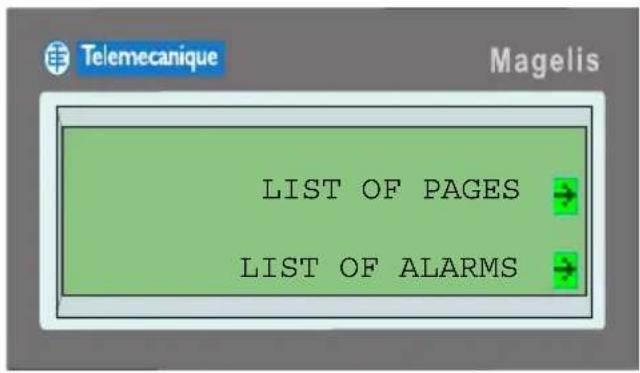
For more information about access to system pages, see section "6. System pages", Page 39.
Scrolling within a page
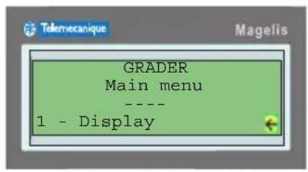
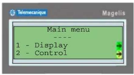
Scrolling is necessary to view the whole of a page, which contains more lines than the screen is capable of displaying. On display, the first n (n being the number of lines on the display unit) lines on the page are displayed. For example, four lines for the XBT N400 display unit.
| XBT ref. Note | |
| N200 No scrolling | |
| N400/N401/N410NU400 | For display units in “input” mode only |
4. Application pages
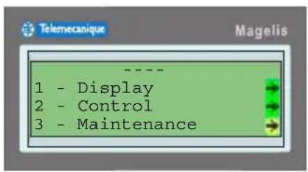
The other lines can be displayed by scrolling up or down the page using the up and down keys on the keypad.




| XBT ref. Note | |
| N200 No scrolling | |
| N400/N401/N410NU400 | For display units in “input” mode only |
5. Alphanumeric fields
Input/Modification of a value
Selection of an input field
By the operator
The input field should be visible on screen. Selection is made using the MOD key:

Pressing the MOD key on the display unit keypad several times in succession runs through the variable fields in input mode from left to right and then from top to bottom.


1st time MOD is pressed:
If no input has been made in any field on the screen since the page was displayed, the top left-hand field on the screen is the input field (field no. 1).
Otherwise it is the last one to have been entered (field no. 1, 2, 3 or 4).
We will assume that field no. 1 is the input field.
2nd time MOD is pressed: Input field no. 2
3rd time MOD is pressed: Input field no. 3
4th time MOD is pressed: Input field no. 4
5th time
MOD is pressed: Input field no. 1, etc.
Field no. 5 cannot be the input field (it is not visible on screen).
| XBT ref. Note | |
| N200 No scrolling | |
| N400/N401/N410NU400 | For display units in “input” mode only |
By the pilot device
The connected device changes a variable field to input mode by writing its number in a word in the dialog table. The number of variable fields can be displayed in the XBT L100• using the Display/Number of fields menu.
First, the application program of the connected device should ensure, again via the dialog table, that the application page where the field appears is actually being displayed. Otherwise there is a risk of selecting a field on another page.
In return, the display writes the number of the field being completed in a word in the dialog table (see chapter C, section 4. Dialog table, Page 53).
Specific feature of this type of selection:
The operator cannot select another variable field until he has completed the one requested by the connected device (MOD key inactive).
■ Entering a value ^(1)
When a field is in input mode, the whole field blinks and three input methods are available: accelerated incremental input, thumbwheel input or direct input.
- Accelerated incremental input: The total value of the field is increased or decreased by pressing keys and .
- Thumbwheel input: First, the digit to be modified is selected and it starts blinking when keys and are pressed. (These keys are managed in the same way as a "drum". This means that on reaching one end of the variable field, you go back to the other end). Next, when keys and are pressed, the digit values are displayed in one direction or the other (these keys are also managed in the same way as a "drum").
| XBT ref. Note | |
| N200/N400/N401/N410NU400 | (1) For display units in “input” mode only |
5. Alphanumeric fields
- Direct input (XBT R4•• only): keys F1 to F12 are dual-label Fx/Nx (function/numeric) keys. They can be used to modify values directly. The correspondence between keys and numeric values is as follows:
| Keys Values | |
| F1 1 | |
| F2 2 | |
| F3 3 | |
| F4 4 | |
| F5 5 | |
| F6 6 | |
| F7 7 | |
| F8 8 | |
| F9 9 | |
| F10 0 | |
| F11 +/- | |
| F12 . | |
Confirming an input

ENTER key
The value entered is transmitted to the connected device. Refreshment of the field, which was in input mode, is active again.
Canceling an input

ESC key
- No write action is performed to the control system
- The value prior to input is redisplayed
- Refreshment of the field, which was in input mode, is active again.
| XBT ref. Note | |
| N200/N400/N401/N410NU400 | For display units in “input” mode only |
5. Alphanumeric fields
Exit input on time out
If no key is pressed for more than one minute, input mode is abandoned automatically:
- No write action is performed to the control system
- The value prior to input is redisplayed
- Refreshment of the field, was in input mode, is active again.
Input report
At the end of input, the pilot device is informed of how the input ended:
- Confirmation
- Cancellation
- Time out
by updating the "Report" word in the dialog table (see chapter C, section 7. Description of dialog-table words, Page 65).
| XBT ref. Note | |
| N200/N400/N401/N410NU400 | For display units in “input” mode only |
■ Display from an application page
The system pages are accessed by means of function keys or navigation links.
When designing the application in XBT L100•, the operator can choose which system pages he wishes to associate with these keys, or these links.
The system pages, which can be accessed by the operator, are:
- Date / Time
- List of pages
- Password
- Language
- Reference
- Protocols
- Manage log
- View log
- Manage alarm list
- View alarm list
- Configure printer
■ Display from the dialog table
During the dialog table read cycle, the display unit may need to display a system page.
For more information about how system pages are displayed by the dialog table, see chapter C, section 7. Description of dialog-table words, Page 65.
| XBT ref. Note | |
| N200/N400/N401/N410NU400 | For display units in “input” mode only |
7. Alarm pages

Alarm displays
When an alarm is displayed, the first line on the display unit is preconfigured (by XBT L100•) to show:
- the dates and times of alarm appearance/disappearance and acknowledgment
- the alarm rank in the alarm list
- the total number of alarms in the list
An alarm is displayed blinking:

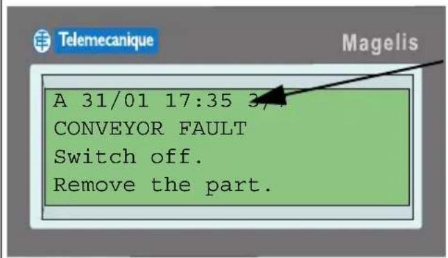
Line time-stamped by the XBT ("A" for Alarm), the alarm text appears blinking and changes to a steady display once it has been acknowledged.
■ Possibility of ignoring alarms

If an alarm is displayed during operation, the ESC key can be used to return to run mode, the alarm is still in the list, and the ALARM indicator light changes to a steady display.
Viewing alarms

Exit viewing alarm pages.


Scroll through the alarm page (up to 25 lines).


Scroll through the list of alarm pages.

The alarm is acknowledged on the display by pressing ENTER. The alarm message changes to a steady display.
| XBT ref. Note | |
| N200 No alarm management | |
| N200/N400/N410NU400R400/R410 | No indicator lights |
7. Alarm pages

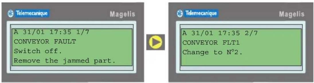
The left and right arrow buttons are used to scroll through the alarm list.
Alarm log
B
Log principles
Alarms are stored one after another. Once the log is full, new alarms overwrite the oldest alarms.
In this way each alarm event (appearance, acknowledgment, disappearance see section Appearance types, Page 20) is recorded and time-stamped.
NOTE: In order for an alarm page to be stored in the log, the store option must be enabled for the page (see chapter C, section Page appearance types, Page 30).
The following functions can be executed:
- initiated by the PLC:
- print log
-clear log
- initiated by the operator:
- view log
- print log
-clear log
| XBT ref. Note | |
| N200 No alarm management | |
7. Alarm pages
NOTE: On XBT N display units, the log is not saved (when the display unit is switched off, the log is cleared).
On XBT R display units, the retention period for the log is limited to twelve hours. Beyond that time there is a possibility that the log will be cleared.
View the log
The alarm log can be viewed from the "MENU" system page (see section Principle of system pages, Page 17).
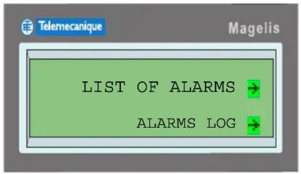
Once inside the log, you can browse through the various alarms (see section Viewing alarms, Page 40).
Clear the log
Clearing initiated by the operator:
In the “MENU” system page select ALARMS LOG and then in the following page select CLEAR.
Clearing initiated by the PLC:
The log is cleared by means of the log reset command word in the dialog table (see chapter C, section Clear log/Advanced functions, Page 78).
| XBT ref. Note | |
| N400/N401/N410NU400 | For display units in “input” mode only |
Principles
Printing can be initiated by the operator or by the PLC.
The following print functions are available:
- Print alarms as a data stream
- Print the alarm log
- Print the list of current alarms
Print alarms as a data stream
The alarm name and status is printed whenever an alarm status changes.
The following information is printed:
- The alarm number
- The name of the alarm page
- The print date
- The print time
- The alarm status
NOTE: In order for an alarm page to be printed, the print option must be enabled for the page (see chapter C, section Page appearance types, Page 30).
Print the alarm log
■ Initiated by the operator
The log is printed in sequential order (sorted by status), with the most recent alarm at the top.
The following information is printed for each alarm:
- Its number
- The name of the alarm page
- The date and time of appearance
- The date and time of acknowledgment
- The date and time of disappearance
| XBT ref. Note | |
| N200/N400/N410NU400R400/R410 | No printer link |
■ Initiated by the PLC
The log is printed by means of the print command word in the dialog table (see chapter C, section Print command, Page 77).
The log is printed in sequential order (sorted by status), with the most recent alarm at the top.
The following information is printed for each alarm:
- The alarm number
- The name of the alarm page
- The date and time of appearance
- The date and time of acknowledgment
- The date and time of disappearance

| !----!----!----!----!----!NUM! ALARM LIST !DD/MM/YYYY HH:MM:SS!ON!ACK!OFF! | ||||
| !----!----!----!----!----!----!002!VAT2:Alarm number 2 !05/03/2004 09:12:05!XX! ! !001!VAT1:Alarm number 1 !05/03/2004 09:10:02! ! !XXX!001!VAT1:Alarm number 1 !05/03/2004 09:08:48! !XXX! !001!VAT1:Alarm number 1 !05/03/2004 09:04:57!XX! ! ! |
Alarm 1 appeared, was acknowledged and then disappeared. Alarm 2 is present but has not been acknowledged.
Print the list of current alarms
The operator can initiate printing of the alarms stored in the alarm list by means of a system page (for more information about the alarm list, see section Storage principle in the alarm list, Page 20)
The alarm number, the name of the alarm page, the print date, the print time and the alarm status are printed.
| XBT ref. Note | |
| N200/N400/N410NU400R400/R410 | No printer link |
8. Printing
Stop printing
This function can be accessed via the system pages.
This request stops the current print job and therefore allows printing to be continued with the next print job. A long print job (e.g., alarm list, log, etc.) can be stopped in this way.
| XBT ref. Note | |
| N400/N410NU400R400/R410 | No printer link |
9. Setting the display unit parameters
It is possible to configure certain display unit parameters when the unit is in run mode, without going into XBT L100•.
The configuration parameters are accessed via the "SYSTEM" system page (Displaying system pages, see section 6. System pages, Page 39).
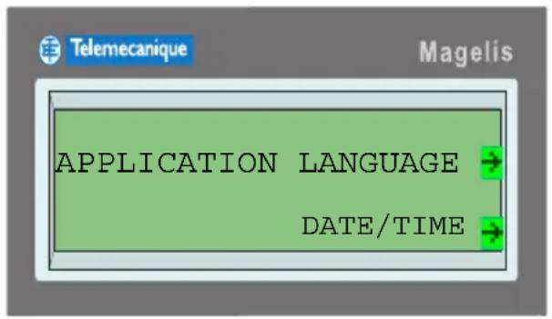
Application language
One of the languages configured by the designer can be chosen.

| XBT ref. Note | |
| N200 No access to the " SYSTEM" system page | |
| N400/N401/N410NU400 | For display units in “input” mode only |
9. Setting the display unit parameters
Date and time
This page is used to set the current date and time. It is also possible to set the date and time display format.
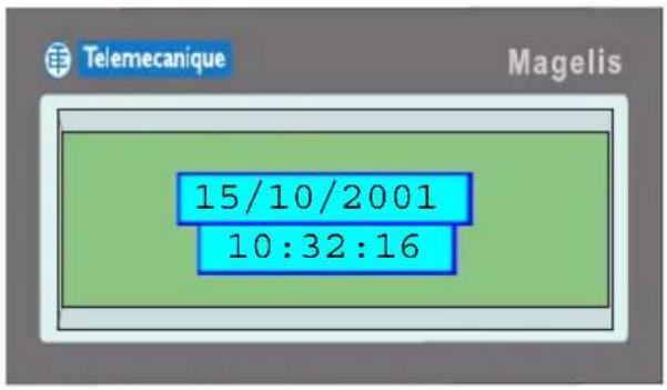
B
■ Entering the date and time
The date and time are entered in the same way as a variable alphanumeric field (see section Entering a value (1), Page 36).
■ Selecting the display format
The display formats are as follows:

| Date formats Time formats | |
| DD/MM/YYYY 24:mm:ss | |
| MM/DD/YYYY 12:mm:ss | |
| YYYY/MM/DD | |
The format can be configured using the XBT L100• program, during display unit configuration (see chapter C, section Step 2 - Configure the terminal parameters, Page 15).
The time format selected applies to all times and dates processed by the software, including the dates and times printed and/or displayed in the log and in the alarm list.
| XBT ref. Note | |
| N200 No access | to the " SYSTEM" system page |
| N400/N401/N410NU400 | For display units in “input” mode only |
9. Setting the display unit parameters

Product references
The display-unit references can be accessed from the system pages.
The display-unit references can be obtained if the designer has provided access to these pages (link to the system pages). The information displayed is as follows:
- The product reference
- The name of the application developed in XBT L100•
- The date and time that the application file was saved in XBT L100•
- The communication protocol name
- The version of XBT L100• used to create the application
- The display unit BIOS reference and version
- The display unit application software reference and version
NOTE: The most important information is placed on the first few lines so that it is displayed consecutively, avoiding the need to scroll through the page.
| XBT ref. Note | |
| N200 No access to the "System" system page | |
| N400/N401/N410NU400 | For display units in “input” mode only |
9. Setting the display unit parameters
Line parameters
This system page is used to display information relating to the communication protocol, such as the speed or parity.
Error counters also appear on this page, and their meaning is as follows:
| Counter Modbus Modbus Slave Uni-Telway | |||
| 1 | Number of responses received without a CRC error by the master | Number of messages received by the terminal, whether or not they are relevant | Number of messages sent and not acknowledged |
| 2 | Number of messages received with a CRC error by the master | Number of messages received with a CRC error | Number of messages sent and refused |
| 3 | Number of exception responses received by the master | Number of error messages returned by the terminal | Number of messages received and not acknowledged |
| 4 | Number of broadcast requests sent by the master | Number of correct messages received by the terminal | Number of messages sent and refused |
| 5 | Number of requests still awaiting a response | Number of broadcast messages received by the terminal | Number of messages sent correctly |
| 6 | Number of ‘PLC not ready’ responses received by the master | Always at 0 | Number of messages received correctly |
| 7 | Number of incorrect characters received | Number of messages not processed because the terminal was not ready | Number of emitting frames sent |
| 8 | Number of requests correctly executed | Number of messages received with parity errors, format errors, etc. | Number of receiving frames received |
| 9 | / | Number of correct messages received and processed by the terminal | / |
| XBT ref. Note | |
| N200 No access to the "System" system page | |
9. Setting the display unit parameters
| XBT ref. Note | |
| / | / |
C
Chapter C
Detailed description of the XBT L100• program
Software functions for creating an application:
- Introduction: Creating Magelis applications 5
- Presentation of the XBT L100• program 6
Launching the program in Windows 6
Presentation of the software 6
- Using XBT L100• software 13
Creating a new application 13
Application pages 27
Alarm pages 29
System pages 31
Alias 32
Navigation links 33
Text 33
Circular text 41
Alphanumeric variable fields 43
Configuring the function keys 49
Functional links 51
- Dialog table 53
Introduction: Concepts 53
Exchanged data 54
Configuring the dialog table 56
- Simulation 58
Introduction 58
Display-unit simulation window 58
PLC simulation window 59
- Transferring an application 63
Connecting the display unit 63
Starting up the display unit 63
Importing an application 63
Exporting an application 64
- Description of dialog-table words 65
Detailed description 67
Contents
1. Introduction: Creating Magelis applications
A Magelis application consists of the entire dialog between the operator and the automated process. In its entirety, this should take account of:
- The criteria relating to the control system:
- production monitoring
- preventive maintenance
- corrective maintenance
- process control
- The user criteria:
- user interface
- level of intervention
- The criteria for creating the actual dialog application:
- programming
- debugging
- upgrading
NOTE: These constraints mean that it is necessary to structure your application. An application should consist of a set of pages, which can be arranged in a tree structure as shown in the figure below:

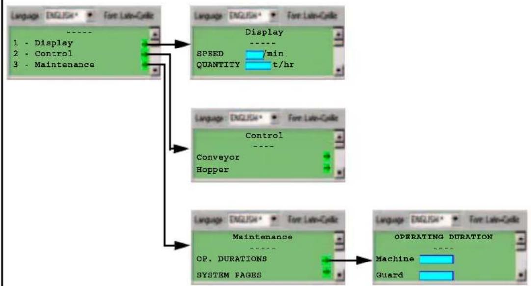
flowchart
graph TD
    A["Language ENGLISH* For: Lat=Cycle"] --> B["1 - Display"]
    A --> C["2 - Control"]
    A --> D["3 - Maintenance"]
    B --> E["Display"]
    C --> F["Control"]
    D --> G["Maintenance"]
    E --> H["SPRED /min"]
    F --> I["Conveyor"]
    F --> J["Hopper"]
    G --> K["OP. DURATIONS"]
    G --> L["SYSTEM PAGES"]
    H --> M["Operating Duration"]
    I --> M
    J --> M
    K --> M
    L --> M
    M --> N["Machine"]
    M --> O["Guard"]
| XBT ref. Note | |
| / | / |
2. Presentation of the XBT L100• program

Launching the program in Windows
The software can be launched:
- By selecting the XBT L100• program from the program menu
- By double-clicking on the XBT L100• icon on the desktop:

- By double-clicking on a dialog application (*.dop) icon
By default, the software opens the last application saved during the previous session.
This option can be modified in the File/Open the Last Application Automatically menu. The creation window then opens.
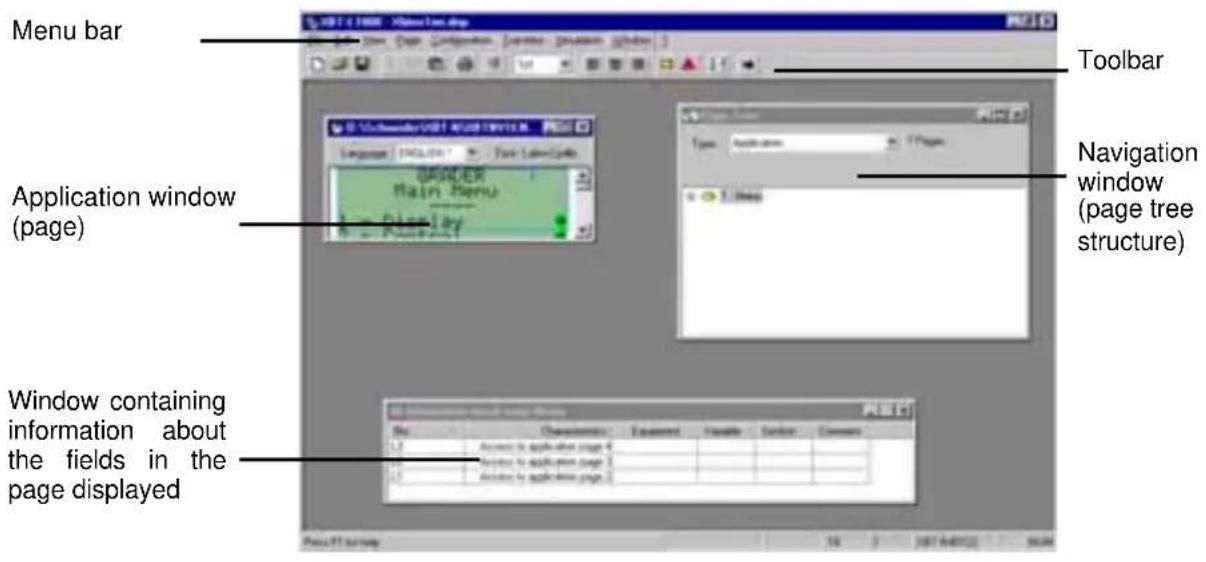

Presentation of the software
Menu bar
If no application has been opened, the following menu bar is displayed:
File View Transfers ?
| XBT ref. Note | |
| / | / |
2. Presentation of the XBT L100• program
If an application has been opened, the menu bar is as follows:
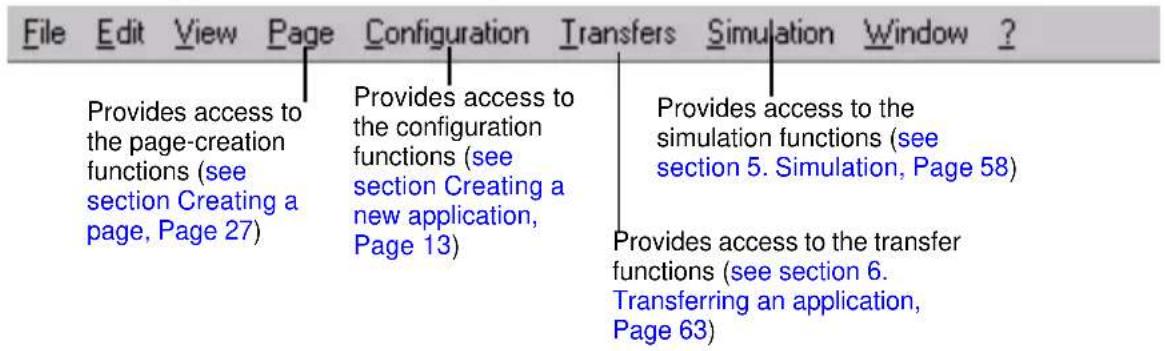
Toolbar
If no application has been opened, the primary window toolbar contains the following buttons:

During editing of an application page or an alarm page, the primary window toolbar contains the following buttons:

NOTE: Depending on the type of display unit selected, certain icons on the toolbar may be inactive (grayed-out).
| XBT ref. Note | |
| / | / |
2. Presentation of the XBT L100• program
Editor toolbar
The editor toolbar appears at the top of the page editor (application or alarm pages). It provides quick access to the options available for the active page in the editor.
This toolbar varies according to page type.
Application page

Alarm page
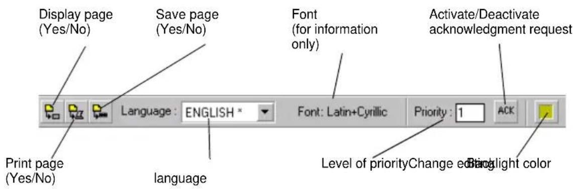
| XBT ref. Note | |
| N200 Latin + Katakana only | |
2. Presentation of the XBT L100• program
Field information window
The field information window displays the properties of fields and links to the current application page.
| No. | Characteristics | Equipment | Variable | Symbol | Comment |
| 1 | 9999999 | API_PLC | 40021 | CST9 | |
| 9 | 9999999 | MASTER | 40121 | ||
| L2 | Access to application page 4 |
The "No." column indicates the number of the field or link.
The "Characteristics" column indicates the field type and length. In the example above, we can see that field no. 1 is a decimal type field and seven characters in length.
The "Symbol" column indicates the equipment symbol to which the variable is linked (see section Configuration equipment window, Page 20).
The "Comment" column indicates the comment linked to the symbol.
Navigation window
The navigation window contains the page structure of the active application and specifies the current page.
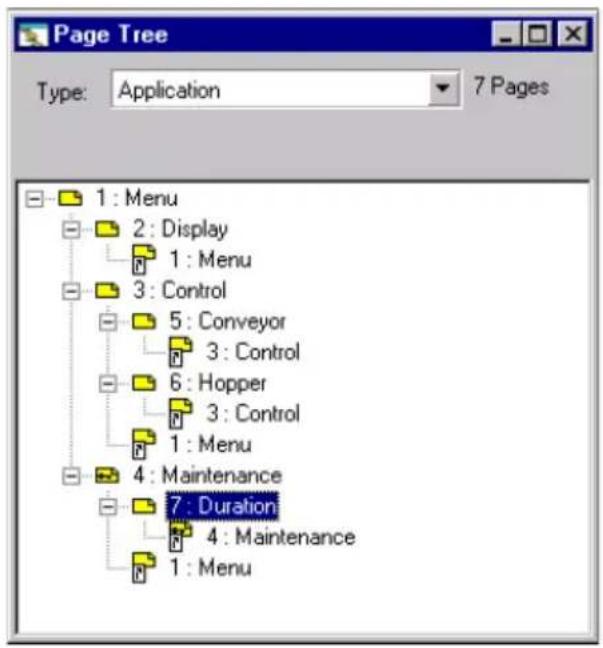
2. Presentation of the XBT L100• program
By clicking on the Type dropdown list, the operator can choose to display the application, alarm or system page tree structure.
The different types of page are represented in the window by the following symbols:
| Symbol Type of page | |
 | Application page |
 | Protected application page |
 | Application-page alias (1) |
 | Protected application-page alias (1) |
 | Alarm page |
 | System page |
 | Protected system page |
 | System-page alias (1) |
 | Protected system-page alias (1) |
| XBT ref. Note | |
| N200 No alarm management | |
(1): Alias see section Alias, Page 32
General
Using copy/paste
The copy/paste function can be used on any object (text, fields, links, etc.), within the same application, or from one application to another, if the equipment symbols are identical. To paste an object in place of a field, text or link, the latter must be selected.
A navigation link can only be pasted if the page to which it is linked exists.
Circular texts copied from an XBT N or XBT R display unit will be truncated according to the space available in the applications on the other ranges and pasted as static text.
It is possible to copy/paste:
- From a page with no Chinese text to a page with no Chinese text
- From a page with Chinese text to a page with Chinese text
- From a page with no Chinese text to a page with Chinese text
NOTE: When pasting text containing Chinese into a non-Chinese language, the Chinese characters are replaced by the "?" character.
When the Chinese text appears within an enumerated list, the Chinese characters are also replaced by the "?" character. In addition, a popup window tells the designer that the content of the enumerated list has been modified.
In the same way, if text is copied/pasted into an application with a different font, the pasted characters are represented by the corresponding character.
| XBT ref. Note | |
| / | / |
2. Presentation of the XBT L100• program
Alignment
Text within a page can be aligned:
- Left
- Center
- Right
To do this, simply go to the line where alignment is required, then click on one of the toolbar buttons.

| XBT ref. Note | |
| / | / |
3. Using XBT L100• software

Creating a new application
To create an application in XBT L100•, click on the button on the toolbar or select New in the File menu.
Applications can be created with or without a wizard.

Creation without a wizard
Creating an application without a wizard involves the following stages:
- Step 1: Select the type of terminal
- Step 2: Configure the terminal parameters
- Step 3: Configure the protocol parameters
- Step 4: Configure the equipment
- Step 5: Select the application languages
- Step 6: Configure the dialogue table
Step 1 - Select the type of terminal
An initial window is used to select the display unit and the protocol associated with the application to be created.
The terminal selection window is as follows:
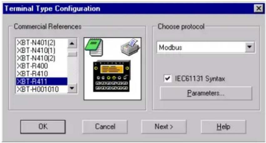
For XBT N display units, it is possible to select a display unit in input mode, or a display unit in control mode. The display-unit keypad varies depending on the selection made.
| XBT ref. Note | |
| / | / |
3. Using XBT L100• software
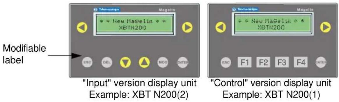
NOTE: When the version of an XBT N display unit changes, the key legends should change (see quick reference guide).
This distinction is indicated in the list of product references by the notation (1) or (2). For example, the reference XBT N200(1) indicates a "control" version XBT N200 display unit, whereas the reference XBT N200(2) indicates an "input" version XBT N200 display unit.
- By confirming with the "OK" button, a new application can be created without using the creation wizard.
- "Clicking" on the "Next >" button guides the designer through the creation of a new application by linking several windows (see section "Creation with a wizard", Page 24).
- "Clicking" on the "Parameter..." button enables access to configuration of the selected protocol parameters (see section "Step 3 - Configure the protocol parameters", Page 19).
- The check box marked "IEC61131 Syntax" is used for the Modbus protocol to choose the syntax used for the variable addresses.
| XBT ref. Note | |
| / | / |
3. Using XBT L100• software
Step 2 - Configure the terminal parameters
This window appears if Terminal Parameters is selected from the Configuration menu.
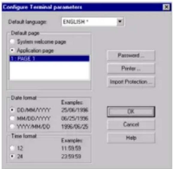
This window is used to configure the following terminal parameters:
- The default language (this language will be used when the terminal is powered up)
- The default page (the selection is made in a list corresponding to the list of existing application pages)
- Application-import protection
- Passwords
- The printer (XBT N401 and XBT R411 only)
- The date format used by the display unit
- The time format used by the display unit
Application-import configuration
This function is used to protect the display unit dialog application to avoid unwanted "hacking".
| XBT ref. Note | |
| N200/N400/N410NU400R400/R410 | No printer link |
3. Using XBT L100• software
It is possible to choose:
- Whether the application can be imported (by default) or not
- Whether or not a password is required for importing
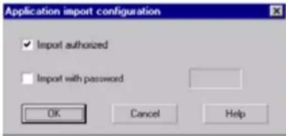
During data input, the password is displayed without encryption. It consists of four ASCII characters ([0..9]+[A..Z]).
If importing has not been authorized and an operator tries to import the application, an error message appears at the start of importing and the transfer is not completed.
If importing has been authorized with a password, the password input screen appears. If the password entered is incorrect, an error message appears and the application is not transferred.
In all cases, exporting remains possible.
Configure printer
This function is used to configure printing from a display unit.
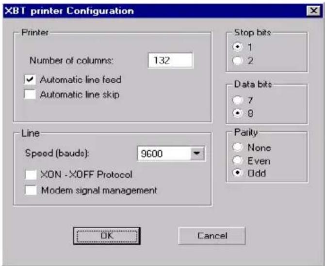
| XBT ref. Note | |
| N200/N400/N410NU400R400/R410 | No printer link |
It is used to configure:
- The number of printer columns: between 10 and 132 (132 by default).
This is the number of characters that can be printed on one line (this depends on the type and/or mode of the connected printer). The most common values are 80 and 132.
- Automatic line skip option: (checked by default)
To go to the beginning of the next line on a printer, two characters must be sent: CR for Carriage Return (the print head is repositioned at the beginning of the line without a vertical shift) and LF for Line Feed (the paper is shifted up one line). In order to use less of the passband, certain printers automatically generate the LF character when they receive the CR character. When the box is checked, only the CR character is sent to the printer. However, if this parameter is configured incorrectly, the following scenarios may arise:
- The box is checked and the printer does not support auto-LF: All the printed text will be superimposed on one another.
- The box is unchecked and the printer supports auto-LF: All lines will be separated by a blank line.
- The transfer speed: (9600 by default)
This is the communication speed configured for the printer. It depends on the type of printer connected. If random printing errors occur, this speed must be reduced on the XBT L100• and on the printer.
- Option for the printer to use the XON/XOFF protocol: (not checked by default)
When the terminal sends data to be printed to the printer, the latter usually stores them in a buffer of limited size. In order to regulate the communication flow, some printers use a protocol called XON/XOFF: When the printer buffer reaches 80% saturation, the printer sends an XOFF command to the terminal, which then suspends printing until the printer sends it an XON character.
When the box is checked, this function is activated. If the box is not checked, there is no flow control. This protocol needs a 3-wire cable (earth, send channel, receive channel) to operate.
| XBT ref. Note | |
| N200/N400/N410NU400R400/R410 | No printer link |
- Management of Modem signals (not checked by default)
This is another flow-regulation protocol: This time, the flow is regulated electronically (no longer via the software as in the case of the XON/XOFF protocol). A cable incorporating 5 wires is required (earth, send channel, receive channel, ready to send, clear to send). Although possible, we do not recommend checking both boxes (XON:XOFF and modem signals) at the same time. Similarly, it is not advisable to uncheck both boxes at the same time, in order to ensure that the printer will not become saturated.
- Number of stop bits (1 by default)
Communication parameter configured for the printer. Enter the value supported by the printer.
- Number of data bits (8 by default)
Communication parameter configured for the printer. Enter the value supported by the printer. Caution: If you send characters with 7 data bits, accented characters and/or characters specific to the language configured may print incorrectly.
- Parity (odd by default)
Communication parameter configured for the printer. Enter the value supported by the printer. Parity is used to detect physical communication errors (change of a 1 to 0, and vice versa, on the line). For this reason, each character sent can be associated with a parity bit. The role of this bit is as follows:
- No parity has been selected, this bit is not present.
- The selected parity is even, each character sent has an even number of bits at 1. For example, to send the character 01110011, you would actually send 011100111. A bit at 1 has been added because there were originally 5 bits at 1 to be sent.
- The selected parity is odd, each character sent has an odd number of bits at 1. For example, to send the character 01110011 you would actually send 011100110. A bit at 0 has been added in order to send an odd number of bits at 1.
| XBT ref. Note | |
| N200/N400/N410NU400R400/R410 | No printer link |
3. Using XBT L100• software
Password configuration

Three passwords, A, B and C can be configured. Each password consists of four ASCII characters ([0..9]+[A..Z]).
These three passwords are configured by default as "1111".
Step 3 - Configure the protocol parameters
This window appears when Protocol Parameters is selected from the Configuration menu.
This window is used to:
- Indicate the protocol line parameters
- Enter parameters specific to the protocol
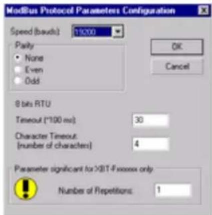
The appearance of the dialog box depends on the protocol selected.
| XBT ref. Note | |
| N200/N400/N410NU400R400/R410 | No printer link |
3. Using XBT L100• software
Step 4 - Configure the equipment
This window appears after selection of Equipment Symbols from the Configuration menu.
Principle
A control system consists of several devices, which may be linked to one or more display units. A device may be a PLC, a computer, a speed drive, etc. The display unit itself is deemed to be a device, enabling it to have its own variables, such as date, time, etc.
From the viewpoint of XBT L100•, a device is defined by two characteristics: the equipment address and symbol. The address depends solely on the protocol used.
One display unit can communicate with up to fifteen different devices.
Configuration equipment window
Select Equipment Symbols from the Configuration menu to create, modify or delete equipment symbols.
![Configure Equipment Symbols Equipments: (Slave) MASTER[1] TWIDO[4] ULTIMA[18] QUANTUM[23] OK Cancel Help Add ... Modify ... Delete Advanced >>](/content/2026/05/760646/images/9d6da2a6710350b8a81989b0c01963e5c27723160f03b99606a9ba4c48053178.jpg)
By default, the list contains one device with a default address, whose symbol is "MASTER". This equipment cannot be deleted, but its name and address can be modified.
A symbol is associated with one address only, and vice versa.
| XBT ref. Note | |
| N200/N400R400 | Mono-equipment |
3. Using XBT L100• software
The equipment creation/modification window differs according to the protocol selected.

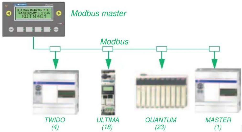
flowchart
graph TD
    A["XBTN401"] --> B["Modbus master"]
    B --> C["TWIDO (4)"]
    B --> D["ULTIMA (18)"]
    B --> E["QUANTUM (23)"]
    B --> F["MASTER (1)"]
    C --> G["Output"]
    D --> H["Output"]
    E --> I["Output"]
    F --> J["Output"]
C
Importing PLC symbols
It is possible to associate variables files with equipment, which appears in the list. These files must have been generated from either PL7, Concept or Twidosoft PLC programming software.
The "Advanced >>" button calls up a zone at the bottom of the configuration window where this association can be made.
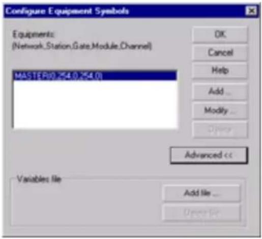
| XBT ref. Note | |
| N200/N400R400 | Mono-equipment |
3. Using XBT L100• software
The "Add File" button enables the designer to select the variables symbol file. The extensions for these files are ".SCY" (PL7), ".TXT" (Concept) or ".TWD" (Twidosoft).
NOTE: The Modbus slave protocol does not require the equipment symbols to be declared since the terminal is totally passive with this protocol.
Step 5 - Select the application languages
Select Application Languages from the Configuration menu to modify the list of languages used by the application.
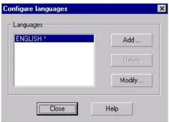
The "Delete" button deletes the selected language. The reference language cannot be deleted.
The "Add" button opens the following window:
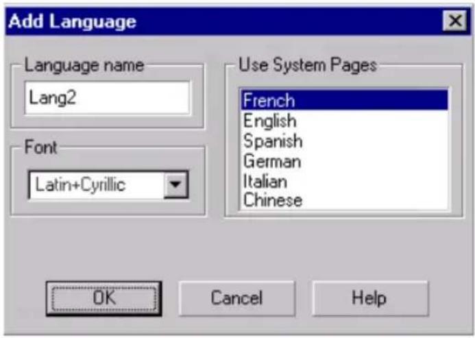
| XBT ref. Note | |
| N200/N400R400 | Mono-equipment |
| N200 Only one font: Latin + Katakana | |
This window can be used to add more languages. It contains:
- A font selection list (Latin+Cyrillic, Latin+Katakana, Cyrillic, Greek or Chinese)
- A zone where the name of the language can be entered
- A list containing the 6 languages available for the system pages (English, French, Spanish, German, Italian and Chinese).
If the Chinese font has not been selected, Chinese does not appear in the list of system-page languages.
NOTE: If the font selected initially was Chinese and the user chooses to stop using this language, Chinese characters already entered in the application will be replaced with “?”.
When there are several languages in the application, by default, the additional language pages are identical to the reference language pages, unless the reference language is Chinese. In this case, the Chinese characters are replaced with “?” (static texts, circular texts and text in enumerated lists) for languages where the Chinese font has not been used.
Any modification of variable fields or links in a page in the reference language (first in the list) is systematically carried through to the other language pages. However, any modification of static text has no effect on the static text on other application language pages. The same applies to text in enumerated lists.
Only static text, circular text and text in enumerated lists can be entered in other language pages. Modification of text in any other language than the reference language has no effect on other language pages. It is not possible to delete, modify, move or add a variable field or a link from a page edited in any other language than the reference language.
A dropdown list in the application primary window toolbar indicates the name of the current application language. If only one application language has been configured, this list is inactive. When the selected language is the reference language, an asterisk ("*") appears after the language name.
| XBT ref. Note | |
| N200 Only one font: Latin + Katakana | |
3. Using XBT L100• software
The reference language is the application development language.
A default language can be defined on opening the application (see section Step 2 - Configure the terminal parameters, Page 15).
Step 6 - Configure the dialog table
Select Dialog Table from the Configuration menu to configure the dialog table and any additional alarm tables, which enable alarms to be triggered by several devices.
(For more information about configuring the dialog table, see section 4. Dialog table, Page 53)
■ Creation with a wizard
The application creation wizard is accessed by clicking on the "Next >" button in the terminal selection window (see section "Step 1 - Select the type of terminal", Page 13).
Step 1 - Enter the application name
This window is used to indicate the name and location of the application file you wish to create ("Browse..." button).

Click "Next >" to proceed to the next step in the wizard.
Click "Cancel" to close the application creation wizard.
| XBT ref. Note | |
| N200/N400R400 | Mono-equipment |
3. Using XBT L100• software
Step 2 - Configure the equipment
This dialog box is used to specify the equipment relating to the application.
![XBT-L1000 application creation assistant List of current equipment: MASTER[1] Modify the list... < Back Next > Cancel Help](/content/2026/05/760646/images/319072ae89e5ebe1dc12923eec858df1decf23bb51597cd379b675a55e6e2e32.jpg)
The "Modify List" button calls up another window where equipment can be added, modified or deleted. For more information, see section "Step 4 - Configure the equipment", Page 20.
Click "< Previous" to go back to the previous step in the wizard.
Click "Next >" to proceed to the next step in the wizard.
Click "Cancel" to close the application creation wizard.
Step 3 - Configure the application languages
This window is used to specify which languages can be used by the application (in the case of multilingual applications).
![XBT-L1000 application creation assistant Configuration of languages Default language ENGLISH [used when the terminal is started up] Application languages ENGLISH * (* = reference language in which the application is entered) < Back Next > Cancel Help](/content/2026/05/760646/images/a7239476461fab891a5bc5d0b391b57b9573091dc98c8a269f79d3debddccf62.jpg)
| XBT ref. Note | |
| / | / |
3. Using XBT L100• software
This window is divided into two parts:
- The "Default language" part consisting of:
- a display area containing the default language
- a "Modify" button, which opens the "Configure Terminal Parameters" window, used to modify the default language on opening
- The "Application languages" part consisting of:
- the list of application languages, with the reference language followed by the "*" symbol. Example: Français *
- a "Modify" button, which opens the "Select Application Language" dialog box
The reference language is the application development language.
Step 4 - Configure the display unit and dialog table parameters

The "Parameter Configuration" button is used to open a new dialog box for configuring the display unit parameters (see section Step 2 - Configure the terminal parameters, Page 15).
The "Configuration" button is used to open the dialog table configuration window. (see section "Step 6 - Configure the dialog table", Page 24)
The "End" button exits wizard mode and terminates application creation.
| XBT ref. Note | |
| / | / |
3. Using XBT L100• software
Application pages
Creating a page
An application page can be created in a number of ways:
- By clicking on the toolbar button

- By pressing F7 on the keypad
- By selecting Application from the Page/New page menu.
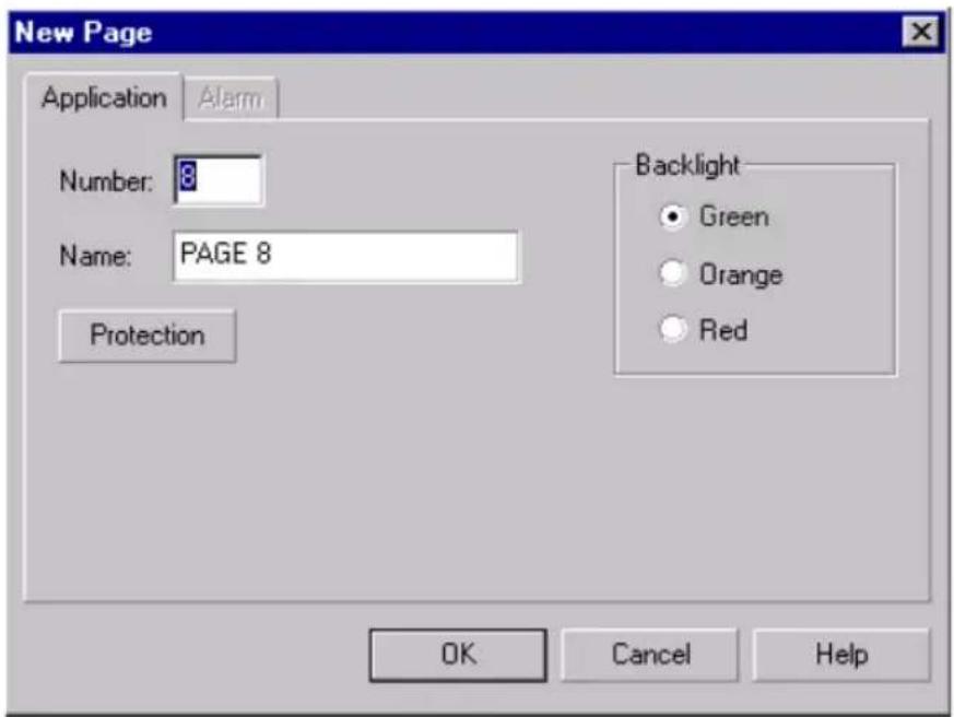
The page name offered by default is "PAGE X" (irrespective of the current language selection), where X is the default number of the new application page.
The page number offered by default is incremented by 1 in relation to the last page created for the current application.
The page name is limited to twelve characters.
The "Protection" button is used to configure access to the page (see section "Protecting a page", Page 28).
It is possible to select the backlight color for the page (green, orange or red) from this window.
| XBT ref. Note | |
| N200/N400/N410NU400R400/R410 | No choice of backlight color |
3. Using XBT L100• software
Page properties
The properties of an application page can be accessed:
- From the menu bar, Page/Properties
- From the page tree structure window, by right-clicking on the selected page
The window is identical to that used for creation.
Protecting a page
The "Protection" button in the creation/properties window of an application page is used to access the window below.
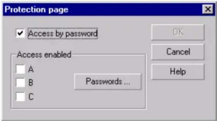
- Check the first box to protect the page.
- Check the passwords (A, B, C), which will be authorized to access this application page.
Click on the "Passwords" button to access the window for changing passwords.
NOTE: When creating an application page, the protection values offered by default are those selected for protection of a previous page.
By default, an application page is not protected.
If the page is protected, the protected application page icon appears in the tree structure window (see section Navigation window, Page 9).
| XBT ref. Note | |
| / | / |
3. Using XBT L100• software

Alarm pages

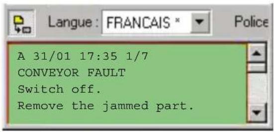

Creation
Alarm pages can only be created if the "Alarm table" function has been selected in the dialog table.
This can be done in a number of ways:
- By clicking on the toolbar button
- By pressing SHIFT+F7 on the keypad
- By selecting New Page/Alarm from the Page menu
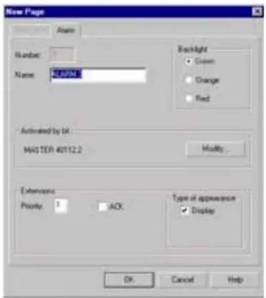
| XBT ref. Note | |
| N200 No alarm management | |
The page name offered by default is “ALARM X” (irrespective of the current language selection), where X is the default number of the new alarm page.
The page number offered by default is incremented by 1 in relation to the last page created for the current application.
The default page name is limited to 32 characters.
The appearance type of the page can also be configured (see section Page appearance types, Page 30).
Next, indicate which bit will activate the alarm page. To do this, simply click on the "Modify..." button.
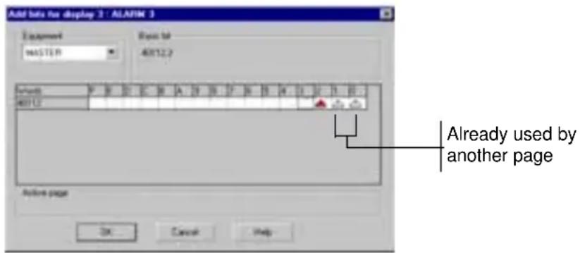
Then simply select the activation bit.
Page appearance types
The buttons for configuring the appearance type of pages are located on the editor toolbar for the alarm pages (see section Editor toolbar, Page 8).
The various types of appearance of the alarm pages are as follows:

Display alarm on screen (this option should be selected if you want the alarm to appear on the screen)

Print alarm (this option should be selected if you want the alarms to be printed as a data stream, see chapter B, section Print alarms as a data stream, Page 43).

Save alarm (this option should be selected if you want the alarms to be stored in the alarm list, see chapter B, section Alarm log, Page 41).
| XBT ref. Note | |
| N200 No alarm management | |
| N200/N400/N410NU400R400/R410 | No printer link |
3. Using XBT L100• software
Page properties
Select Page/Properties from the Page menu to access the properties of an alarm page.
The dialog box is identical to that used for creation.
- Alarm acknowledgments
It is possible to define whether the alarm must be acknowledged:
- Acknowledgment not obligatory: The alarm disappears from the list of alarms once the problem detected has been resolved
- Acknowledgment obligatory: The alarm only disappears from the list of alarms if the problem detected has been resolved and the alarm has actually been acknowledged.
To use the obligatory acknowledgment option, first select an alarm page and click on the ACK button.
System pages
Page properties
The properties of a system page can be accessed in the same way as for application pages.
Only the name and protection of system pages can be modified.
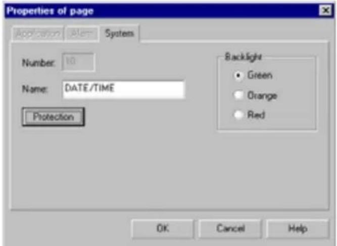
| XBT ref. Note | |
| N200 No alarm management | |
3. Using XBT L100• software
Alias
The tree structure representation of application and system pages uses aliases for navigation between pages.
It is quite possible to use the same application page in several tree structures.

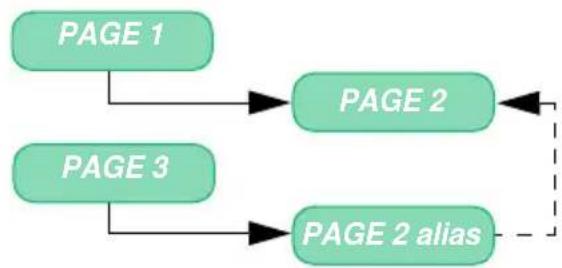
flowchart
graph TD
    A["PAGE 1"] --> B["PAGE 2"]
    C["PAGE 3"] --> D["PAGE 2 alias"]
    B -.-> D
An alias is represented as a page. A page can call up any other page, itself included, as shown in the following example:

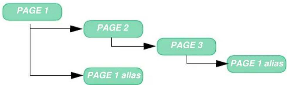
flowchart
graph TD
    A["PAGE 1"] --> B["PAGE 2"]
    A --> C["PAGE 1 alias"]
    B --> D["PAGE 3"]
    C --> D
    D --> E["PAGE 1 alias"]
An alias always has the same name and number as the original page.
NOTE: It is impossible to link alarm pages, and alarm page aliases do not therefore exist.
| XBT ref. Note | |
| / | / |
3. Using XBT L100• software
Navigation links
Navigation links are objects displayed on the screen, which can be used to navigate between the various application pages, using the

Text
Text can be entered in n different languages (n being limited by the size of the display-unit memory), and the display unit displays the text corresponding to the selected language.
Properties
A single-size character is encoded on a rectangle 6 pixels wide and 8 pixels high (5 pixels wide by 7 pixels high for XBT N200s). Its sizing handle is located on the top left-hand corner of this rectangle.
For the default font, ASCII characters are encoded in a single-size character (6 x 8) with separation of one pixel at the left and the bottom (i.e., a rectangle of 5 x 7 pixels).
Size of a single-size character: Default font: 5 x 7 pixels
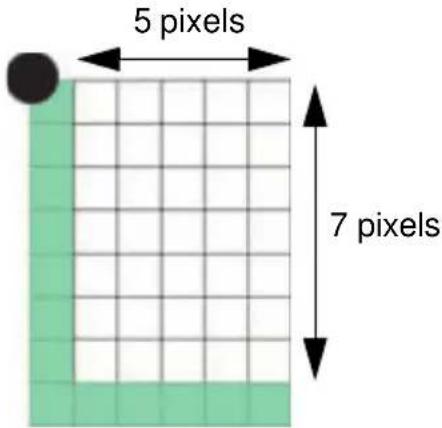
| XBT ref. Note | |
| N200 One character size: 5 x 7 pixels | |
| N400/N401/N410NU400R400/R410/R411 | 10 character sizes: 6 x 8 to 36 x 32 pixels |
3. Using XBT L100• software
Characters can be represented in 10 different sizes extrapolated from the single-size font (double width, double height, double size, etc.). Maximum number of characters on the screen according to the size:
| Size of characters L x H compared to single size | Number of characters (HxL) | ||
| XBT-N200 | XBT N40• XBT NU400 XBT R4•• | XBT N40• XBT NU400 XBT R4•• (Chinese (1)) | |
| Single size 1 X 1 | 2X20 4X20 | - | |
| DoubleH 1 X 2 | 4X20 2 x 20 | - | |
| Double L 2 X 1 | - | 4 | x |
| Double size 2 X 2 | - 2x10 2x10 | ||
| Double L Quadruple H 2 X 4 | - 1x10 1x10 | ||
| Triple L Double H 3 X 2 | - 2x6 - | ||
| Triple L Quadruple H 3 X 4 | - 1x6 - | ||
| Quadruple L Double H 4 X 2 | - 2x5 2x5 | ||
| Quadruple size 4 X 4 | - 1x5 1x5 | ||
| Sextuple L Quadruple H 6 X 4 | - 1x3 1x3 | ||
Characters are positioned on a grid defined by the number of characters and the number of lines the display unit can support.
A character has its own set of a parameters. This makes it possible to have characters with different properties on the same line.
Example for a display unit with 4 lines x 20 characters:
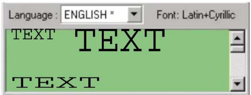
| XBT ref. Note | |
| N200 One character size: 5 x 7 pixels | |
| N400/N401/N410NU400R400/R410/R411 | 10 character sizes: 6 x 8 to 36 x 32 pixels |
(1): If the Chinese font has been selected
3. Using XBT L100• software
For Chinese characters, if the current size is not permitted and the user enters a Chinese character, the size is automatically updated as shown in the following table:
| Current size New size after using a Chinese character | |
| 1X1 2X2 | |
| 1X2 2X2 | |
| 2X1 2X2 | |
| 2X2 No change | |
| 2X4 No change | |
| 3x2 4x2 | |
| 3x4 4x4 | |
| 4X2 No change | |
| 4X4 No change | |
| 6x4 No change | |
At the end of the input in Chinese font, the new size will be retained for the following inputs.
Character fonts
The character fonts available are "Latin+Cyrillic" or "Latin+Katakana", "Cyrillic", "Greek" or "Chinese".
"Latin and Cyrillic" font
![□! " # $ % & ' ( ) * + , - . / 0 1 2 3 4 5 6 7 8 9 : ; < = > ? a A B C D E F G H I J K L M N O P Q R S T U V W X Y Z [ ¥ ] ^ _ ` a b c d e f g h i j k l m n o p q r s t u v w x y z ( | ) → ← k x b u u z φ r f u u φ l u ? e n p r n o ± y x v b y z w z w u y w o e u u t φ r t u u z l c t k n p r y z y x y z m z m y b A A A A A A K C E E E E E i i i T o n o o o o o o x o u u o u v P p a a a a a a a e e e e e i i i i o o o o o o ÷ o u u u u 0 1 ■](/content/2026/05/760646/images/2b211f453a39e7f892d804142b881d48bc10d7c2cb86ef1d0e79e9cb932bf23d.jpg)
"Latin and Katakana" font

The Chinese font consists of:
- The ASCII character set (containing Latin characters)
- The Katakana extended ASCII character set
- The Chinese character set
"Cyrillic" font
![! " # $ % & ? ( ) * + , - . / 0 1 2 3 4 5 6 7 8 9 : ; < = > ? A B C D E F G H I J K L M N O P Q R S T U U W X Y Z [ ¥ ] ^ _ a b c d e f g h i j k l m n o p q r s t u v w x y z ( I ) → ← α b c d e f g h i j k l m n o p q r s t u v w x y z ( I ) → ← α b c d e f g h i j k l m n o p q r s t u v w x y z ( I ) → ← α b c d e f g h i j k l m n o p q r s t u v w x y z ( I ) → ← α b c d.e f g h i j k l m n o p q r s t u v w x y z ( I ) → ← α b c d.e f g h i j k l m n o p q r s t u v w x y z ( I ) → ← α b c d.e f g h i j k l m n o p q r s t u v w x y z ( I ) → ← α b c d.e f g h e f g h e f g h e f g h e f g h e f g h e f g h e f g h e f g h e f g h e f g h e f g h e f g h e f g h e f g h e f g h e f g h e f g h e f g h e f g h e f g h e f g h e f g h e f g h e f g h e f g h h e f g h e f g h e f g h e f g h e f g h e f g h e f g h e f g h e f g h e f g h e f g h e f g h e f g h e f g h e f g h e f g h e f g h e f g h e f g h e f g h e f g h e f g h e f g h e f g h e f f α b c d.e f g h e f g h e f g h e f g h e f g h e f g h e f g h e f g h e f g h e f g h e f g h e f g h e f g h e f g h e f g h e f g h e f g h e f g h e f g h e f g h e f g h e f g h e f g h e fg α b c d.e f g h e f g h e f g h e f g h e f g h e f g h e f g h e f g h e f g h e f g h e f g h e f g h e f g h e f g h e f g h e f g h e f g h e f g h e f g h e f g h e f g h e f g h e f g h e f a α b c d.e f g h e f g h e f g h e f g h e f g h e f g h e f g h e f g h e f g h e f g h e f g h e f g h e f g h e f g h e f g h e f a α b c d.e f g h e f g h e f g h e f g h e f g h e f g h e f g h e f g h he α b c d.e f g h e f g h he α b c d.e f g h he α b c d.e f g he α b c d.e f g he α b c d.e f g he α b c d.e f g he α b c d.e f g he α b c d.e f g he α b c d.e f g he α b c d.e f g he α b c d.e f g he α b c d.e f g he α b c d.e f g he α b c d.e f g his α b c d.e f g his α b c d.e f g his α b c d.e f g his α b c d.e f g his α b c d.e f g his α b c d.e f g his α b c d.e f g his α b c d.e fg his α b c d.ef his α b c d.ef his α b c d.ef his α b c d.ef his α b c d.ef his α b c d.ef his α b c d.ef his α b c d.ef his α b c d.ef his α b c d.ef his α b c d.ef his α b c d.ef his α b c d.ef his αb cdefti αb defti αb defti αb defti αb defti αb defti αb defti αb defti αb defti αb defti αb defti αb defti αb defti αb defti αb defti αb defti αb defti αb defti γbdefti γbdefti γbdefti γbdefti γbdefti γbdefti γbdefti γbdefti γbdefti γbdefti γbdefti γbdefti γbdefti γbdefti γbdefti γbdefti](/content/2026/05/760646/images/31acb2b2ae8e5fca6a9ae2a7b7a85336a734067caeed3cfe4fe88e126d48bc2a.jpg)
"Greek" font
![! " # $ % & ' ( ) * + , - . / 0 1 2 3 4 5 6 7 8 9 : ; < = > ? A B C D E F G H I J K L M N O P Q R S T U U W X Y Z [ ¥ ] ^ _ a b c d e f g h i j k l m n o p q r s t u v w x y z ( | ) → ← L L J = || = || F F π ∥ || = ∥ ' ' € : : § 0 << - - - - ° ± 1 ' ^ ' A ' E ' H ' I >> '0 '2 'Y 'Q A B Γ Δ E Z H θ I K Δ M N = 0 Π P Σ T Y φ X ψ Ω i v 'α 'ε 'h / α β γ δ ε ζ n θ i k λ μ v ξ o n p c σ τ v φ x ψ w i U δ δ Ω](/content/2026/05/760646/images/a147bad6d6317c8f59d8f82062f701248f4c7a5ae5c908371ba61e012916ef12.jpg)
The character font is selected in the terminal parameters (see section "Step 2 - Configure the terminal parameters", Page 15).
| XBT ref. Note | |
| N200 Only one font: Latin + Katakana | |
3. Using XBT L100• software
Modifiable characters
For all fonts used by XBT N/XBT R display units, the first 96 characters cannot be edited.
Special characters in the Configuration menu.
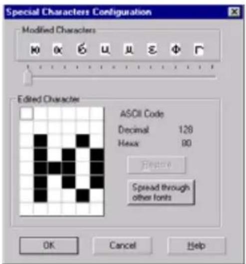
This window contains a "Spread Through Other Fonts" button, which can be used to apply the character modification to other fonts in the application.
Inserting special characters
It is possible to insert a character, which does not exist on the keypad (special character or without equivalent on the keypad) when entering a piece of text or values from an enumerated list.
The copy/paste mechanism is used to insert special characters.
| XBT ref. Note | |
| N200 5 modifiable characters | |
| N400/N401/N410NU400R400/R410/R411 | 125 modifiable characters |
3. Using XBT L100• software
Select Insert Characters in the Edit menu to access the following character table:
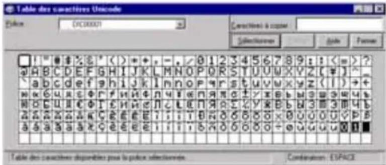
Select the desired character and press the Copy button. Then simply paste the selection.
This function is also useful for displaying all the characters in the font selected for the application.
Inserting Chinese characters
Chinese writing does not consist of letters, but of ideograms, which represent an idea or a concept. A word would consist of one or more of these ideograms and a sentence would consist of one or more of these words.
A special program, called IME (Input Method Editor), is required, which can be used to simulate a keyboard using the simplified Chinese alphabet, which consists of approximately 7000 ideograms.
To enter a word, the designer types it phonetically on the keyboard, and a data-processing system then finds the best ideogram for this word. If the data-processing system cannot determine the right ideogram for this word (for example in the case of homonyms), it suggests all the words, which might correspond to this pronunciation, and the designer can then select the most suitable ideogram from the list of suggestions.
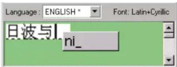
| XBT ref. Note | |
| N200 Only one font: Latin + Katakana | |
3. Using XBT L100• software
Importing/Exporting text for translation
This function is used to translate a dialog application into several languages.
Recommended methods:
1 - Enter the monolingual dialog application in the XBT L100•.
2 - Add the desired languages ("Application languages configuration"). The original texts are copied in each language.
3 - Export the texts ("File\Export Texts") to a new file (for all languages except Chinese).
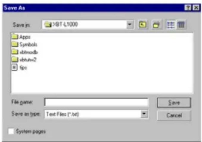
C
4 - Check the "System Pages" box. This also enables the user to translate the display-unit system messages.
The following information is exported (or imported):
- Page names
- Application-page text (application, alarm, system pages)
- Texts contained in the items "circular texts
- Text in enumerated list-type alphanumeric fields
| XBT ref. Note | |
| / | / |
3. Using XBT L100• software
When exporting text, the information is recorded as follows: one column per language (separator: tab) and one line per text. There are as many columns as languages.

The first column contains the texts in the reference language. They must not be modified.
5 - Translate the texts (columns 2 and next) using the Windows application you selected (e.g.: Microsoft Excel). Save the file and quit the Windows application.
6 - Import the translations for all languages other than Chinese ("File\Import translations").
NOTE: In cases where the reference language is Chinese, it is impossible to import/export: The menu is grayed-out.
Similarly, Chinese text can neither be exported, nor imported. Thus, a multilingual English/Chinese/French application will only be able to import English and French text.
| XBT ref. Note | |
| N200 Only one font: Latin + Katakana | |
3. Using XBT L100• software

Circular text

Principles
It is now possible to display information running to more than 20 characters on a single line.
The circular text option allows the text to be scrolled like a banner at a speed of 3 characters per second.

Scrolling of the text "WELCOME TO SCHNEIDER"
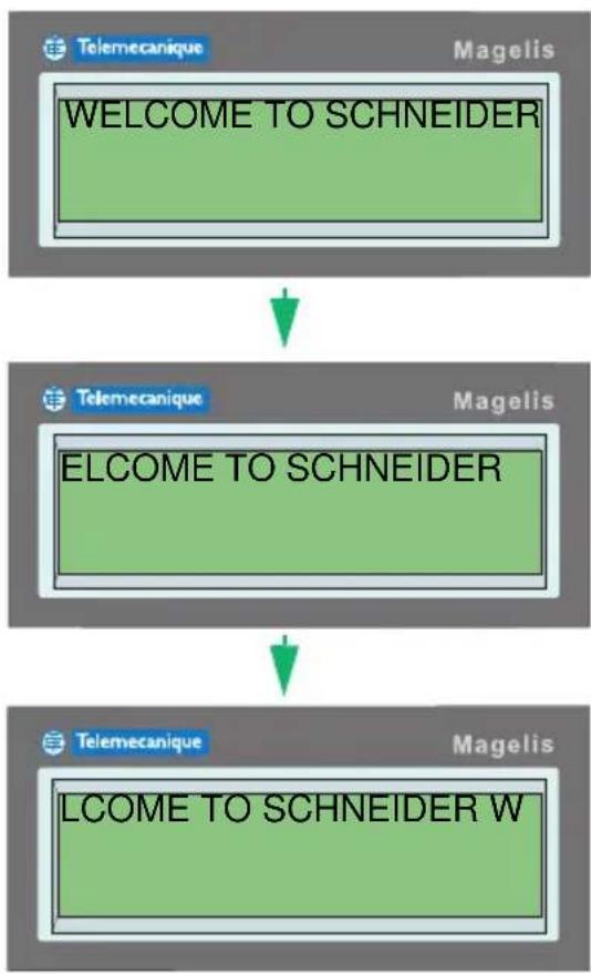
flowchart
graph TD
    A["WELCOME TO SCHNEIDER"] --> B["TElemecanique"]
    B --> C["LCOME TO SCHNEIDER W"]
C
| XBT ref. Note | |
| / | / |
3. Using XBT L100• software
Creation
A circular text can be created in a number of ways:
- By clicking on the toolbar button
- By pressing SHIFT+F9 on the keypad
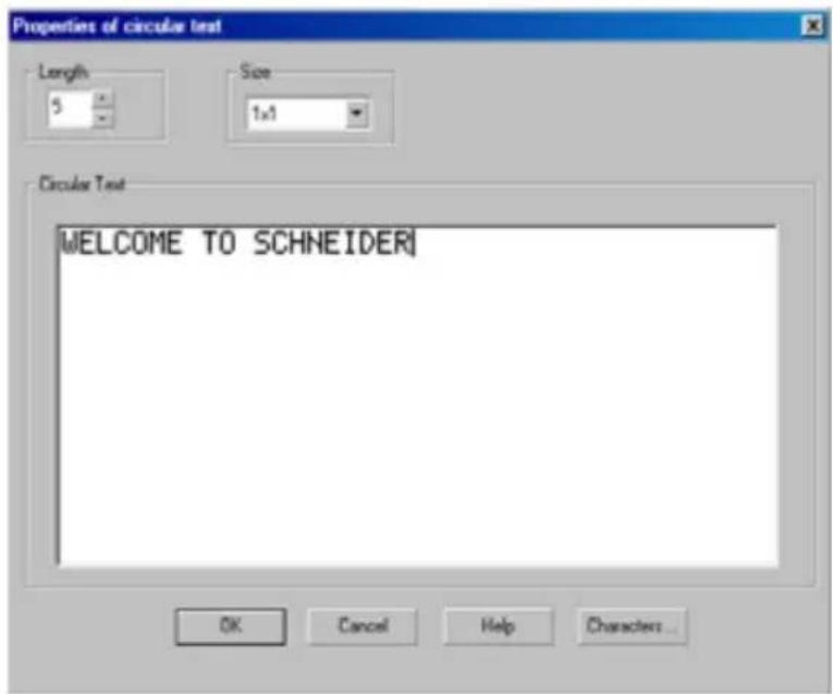
Length:
This is the number of characters that are visible on the screen at the same time. A length of 5 means that only 5 characters will be visible at one time.
Size:
This field can be used to select the character size.
Circular text:
Enter the scrolling text in this field. The maximum length of this text is 256 characters.
Properties
The properties of a circular text can be viewed by double-clicking above it.
The dialog box is identical to that used for creation.
| XBT ref. Note | |
| / | / |
3. Using XBT L100• software
Alphanumeric variable fields
These fields are used to display the value of a variable in the display unit or the connected equipment.
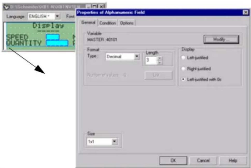
C
Field properties
Display format
- Binary
- Decimal
- Hexadecimal
- ASCII
- Enumerated list
Size:
The content of the fields is displayed with the same character fonts as static and circular texts. The size options are therefore the same.
Length:
1 to n digits, n depending on the display format and the type of data displayed.
| XBT ref. Note | |
| / | / |
3. Using XBT L100• software
The "Modify" button calls up the window where certain variable information can be modified.

NOTE: If the number of digits in the whole value to be displayed is more than the number of digits that can be displayed, the alphanumeric variable field displays an error message.
Variables of associated connected equipment:
| Word bit Word | Double word | Floating String | |||
| Binary X | X | ||||
| Decimal X | X | X | |||
| Hexadecimal X | X | ||||
| Enumerated list X | X | X | X | ||
| ASCII X | |||||
Operator access to fields:
The following access options are available:
- Read: Display only.
- Write: Possibility of entering the variable value, without possibility of reading it. This instance is reserved for certain variables, which cannot be read.
| XBT ref. Note | |
| / | / |
3. Using XBT L100• software
- Immediate write: Incremental input and adjustment of the variable value. Adjustment enables the field value to be gradually increased or decreased without the need to confirm using ENTER.
- Read/write: Display and possibility of modification of the field value.
- Immediate read/write: Display and possibility of incremental input and adjustment of the variable value. Adjustment enables the field value to be gradually increased or decreased without the need to confirm using ENTER.
Protection:
Access to a field can be password-protected. The value represented by the field cannot be modified by the user unless the corresponding password has been entered.
NOTE: If there is no password configured for the field (neither A, B, nor C), it will only be possible to enter it through the dialog table ("field number to be entered" field).
Limits:
Min/Max limits associated with the variable objects are used to:
- Signal to the operator that the variable value entered by the connected equipment is not within the defined interval [Min, Max].
- Ensure that the value entered by the operator is within a given interval.
These limits can be accessed via the "Options" tab.
Constant limits:
The values of constant limits are entered when the application is designed in XBT L100•. These values cannot be modified in running mode.
Variable limits:
These are associated with variables for the connected equipment, and can therefore be modified by this equipment in running mode.
The variables associated with the limits are the same type as the variable associated with the variable object (words, floating points, etc.).
| XBT ref. Note | |
| / | / |
NOTE: These variables are only read when the request is made to display the page containing the variable object concerned.
Conversion
The value of the connected equipment variable can be modified using the following formula:
$$ Y = (A ^ {*} X) + B \text { where } $$
- A and B: Constants (floating points) entered during configuration with XBT L100•.
- X: Variable read in the control system.
- Y: Whatever is displayed by the variable object.
This conversion is configured via the "Options" tab.
Display:
Used to specify how the digits representing the value will be placed in the space reserved for the alphanumeric field.
- For a decimal type field, the following alignment options are offered:
- Left
- Right (default)
- Right with display of non-significant zeros

Left alignment:
123
Right alignment:
123
Non-significant zeros (completed with leading zeros):
000123
- For other formats, alignment is automatic:
- Binary: Aligned right with the addition of leading zeros
- Hexadecimal: Aligned right with the addition of leading zeros
- Enumerated list: Aligned left with the addition of "space" characters to the right
- ASCII: Aligned left with the addition of "space" characters to the right
| XBT ref. Note | |
| / | / |
3. Using XBT L100• software
Enumerated lists
An enumerated list is a list of pairs of values/text. The advantage of this type of list is that text can be displayed in a variable field according to the value of a PLC variable.
Text type values in enumerated lists can only be in ASCII. However, text associated with these ASCII values is written in the language of the active page, and can therefore be written in Chinese.
| Maximum value | |
| Number of texts per list 64 | |
| Characters per text item 20 |
In cases where the selected PLC object equals "BIT", there are only two possible values: 0 and 1.
Selecting "Enumerated list" as the display type makes the "List..." button active.
The "General" tab then appears as shown below:
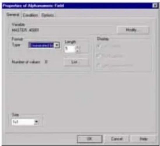
The "Number of values" field is also active and gives the number of values entered in the list.
The "List..." button is used to open a dialog box, which can be used to create, modify and delete value/text pairs in the enumerated list associated with the variable field.
| XBT ref. Note | |
| / | / |
3. Using XBT L100• software

NOTE: A "Characters" button is used to open the tool for selecting special characters. The font displayed is the application font.
Condition
The "Condition" tab is used to enter a calculation formula conditioning display of the value.
![Properties of Alphanumeric Field General Condition Options A Variable... MASTER:40101 >= 10 B Variable... MASTER:40101 <= 50 C Variable... API_PLC:40102 > 200 Field displayed it A AND [ B OR C ] MASTER:40101 >= 10 AND (MASTER:40101 <= 50 OR API_PLC:40102 > 200) Attention: Evaluation on display of the page OK Cancel Help](/content/2026/05/760646/images/f938724c8e14a97b40e2dca8933318557f920345fe6dfe174773e234ed60f77d.jpg)
The condition can include a maximum of 3 comparisons linked by logical operators:
OR, AND and XOR.
The possible comparisons are: =, <>, >, >=, <, <=
| XBT ref. Note | |
| / | / |
3. Using XBT L100• software
A comparison has a variable on the left and a constant on the right. Check boxes in front of each comparison are used to create a condition with 1, 2 or 3 comparisons.
The "Variable" button is used to modify the variable address.
The condition does not take non-activated conditions into account (check box empty).
A reminder of the combination then appears (in the "Field displayed if" part) in plain text.
The variable field is displayed if the condition is TRUE, otherwise it is not displayed.
NOTE: The conditions are only assessed when the page containing the variable field is displayed.
Configuring the function keys
This operation is performed by selecting Function keys from the Configuration menu.
Function keys are configured in blocks of 4.
Blocks of keys, which cannot be configured for the terminal, are inactive.
A function key can be one of 2 types:
- "Page access" type: Access to an application or system page
- "Command" type
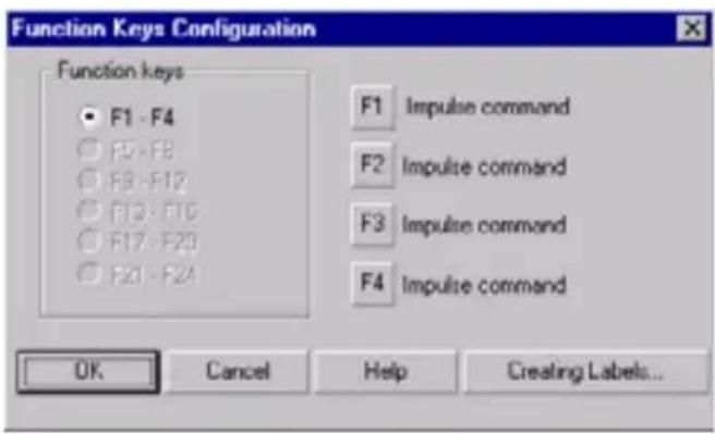
| XBT ref. Note | |
| N200/N400/N401/N410 NU400 | For display units in “control” mode only |
3. Using XBT L100• software
For a command type key, the designer can choose the type of key action:
- Toggle - Impulse
By default, each function key is configured as an impulse command key.
Creating labels
A "Creating Labels" button simplifies printing on the blank labels supplied with the display unit.
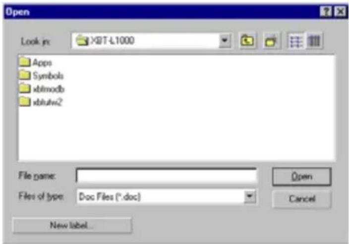
All product ranges have a different sheet reference and hence a different format.
There is one model for XBT N display units (N4_label.dot) and one model for XBT R display units (R4_label.dot).
An existing "*.doc" file can be opened or a new file can be created.
NOTE: As each printer is configured with different margins, it is advisable to test print on a sheet of paper before using a sheet of labels.
The models can also be opened directly in Microsoft WORD without using XBT L100•.
| XBT ref. Note | |
| / | / |
Functional links
Creating links
Links are objects displayed on screen, which are used to allocate functions to the and keys on the display unit keypad.
There are 2 types of link:
- Navigation links: for calling an application or system page
-
Functional links of the following type:
-
Impulse command
- Toggle command
- Write value
1 to 2 links can be programmed per line (1 link maximum in each direction).
A link can be inserted if:
- The selected page is an application page
- The line where the cursor appears does not already have a link in both directions
- The space available for locating the cursor allows a link to be embedded (a functional link consists of two characters).
- The application language associated with the page currently being printed is the reference language
| XBT ref. Note | |
| / | / |
3. Using XBT L100• software
Configuration
This operation is performed by double-clicking on a functional link.
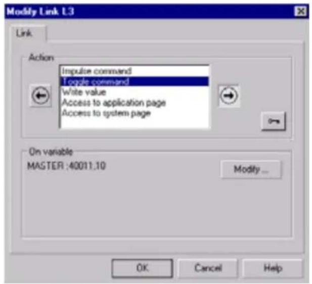
NOTE: For XBT N display units in “control” mode, each page can only contain a maximum of two navigation links (one in each direction) (vertical scrolling not possible).
| XBT ref. Note | |
| / | / |
Introduction: Concepts
Human/machine dialogue between the Magelis display unit and the PLC consists of an exchange of data between the two devices.
With any communication problem, define the following information:
- The protocol
- Etc.
- The data to be exchanged
The dialog table is used to perform the main display-unit functions:
- Feed back alarms from the control system (except XBT N200)
- Send commands to the control system using the image of the function keys
- Signal to the operator that a particular action has been authorized, by means of LEDs integrated in the keypad (XBT N401/R411)
The dialog table also enables the control system to control the product almost as well as an operator:
- Display a page
- Change a variable field to input mode.
Moreover, the dialog table performs some functions that could be deemed secondary (secondary because their purpose is not to give instructions to the display unit or the pilot equipment), such as:
- Set terminal clock
- Lock certain keys on the keypad
- Etc.
Finally, the dialog table contains service information, such as:
- Authorization to interpret a table
- Communication monitoring
The dialog table located in the PLC consists of "n" consecutive words (16-bit words). The number of words in the table depends on the choice of status data and commands to be processed during dialog.
The XBT L100• program is used to make this selection.
| XBT ref. Note | |
| N200 No alarm management | |
| N200/N400/N410NU400R400/R410 | No indicator lights |
4. Dialog table
The display unit reads and writes the table in the PLC.
On power-up or restarting communication, the display unit reads the command table and writes the status table.
In the event of a problem, the display unit informs the user with a message.
NOTE: The "Authorization" word is used as a safety measure for the PLC. In fact, when this word has the incorrect value in the PLC, the display unit does not write any dialog table words to the PLC. Nor will it interpret the command words in the dialog table.

Exchanged data
The dialog table is accessed cyclically in two phases: first a read phase, then a write phase. A few notorious exceptions should be pointed out, for example the images of the function keys or the images of the keypad keys, which are updated immediately.
It is also important to note functions are processed in the order in which they are stored in the dialog table, for either reading or writing: The function read first is the first to be processed, and the function written first is the first to have been processed (except for key images).
The structure of a table is always as follows:
| Block 1 Part containing the XBT -> PLC words |
| Block 2 Part containing the XBT <-> PLC words |
| Block 3 Part containing the XBT <- PLC words |
->, <->, <- : Direction of communication
From the viewpoint of the display unit, on each cycle there is:
1) A read phase: Blocks 2 and 3 are retrieved
2) A write phase: Blocks 1 and 2 are updated if necessary
| XBT ref. Note | |
| / | / |
The notion of a block is extremely useful in certain protocols, which support what is known as optimization: Instead of reading a series of words in the equipment word by word, they can be read in blocks, which is much faster.
Command data sent by the PLC to the display unit
This involves the following commands:
- Advanced functions
- Terminal language
- Display an application page
- Display alarm pages
- Lock keys
- Variable field input request
- Control of indicator lights associated with the function keys
- Set real-time clock command
- Write table authorization
- Print instructions
■ Status data sent by the display unit to the PLC
This involves the following states:
- The display-unit status:
- display-unit configuration mode
- confirmation of entries with the
- cancellation of an input with the
- cancellation of an input after a time-out
- current language
- new time given by the operator


- The number of the page displayed
- The number of the last field entered
- The image of the keypad keys
- The real-time clock status (date and time)
- Communication monitoring
- The number of the last alarm to be acknowledged
- Application checksum
- Terminal advanced status
- Log fill level
| XBT ref. Note | |
| / | / |
4. Dialog table
■ Common data sent/received
- Page number to be processed
- Field number to be entered
Configuring the dialog table
This operation is performed by selecting Dialog Table from the Configuration menu.
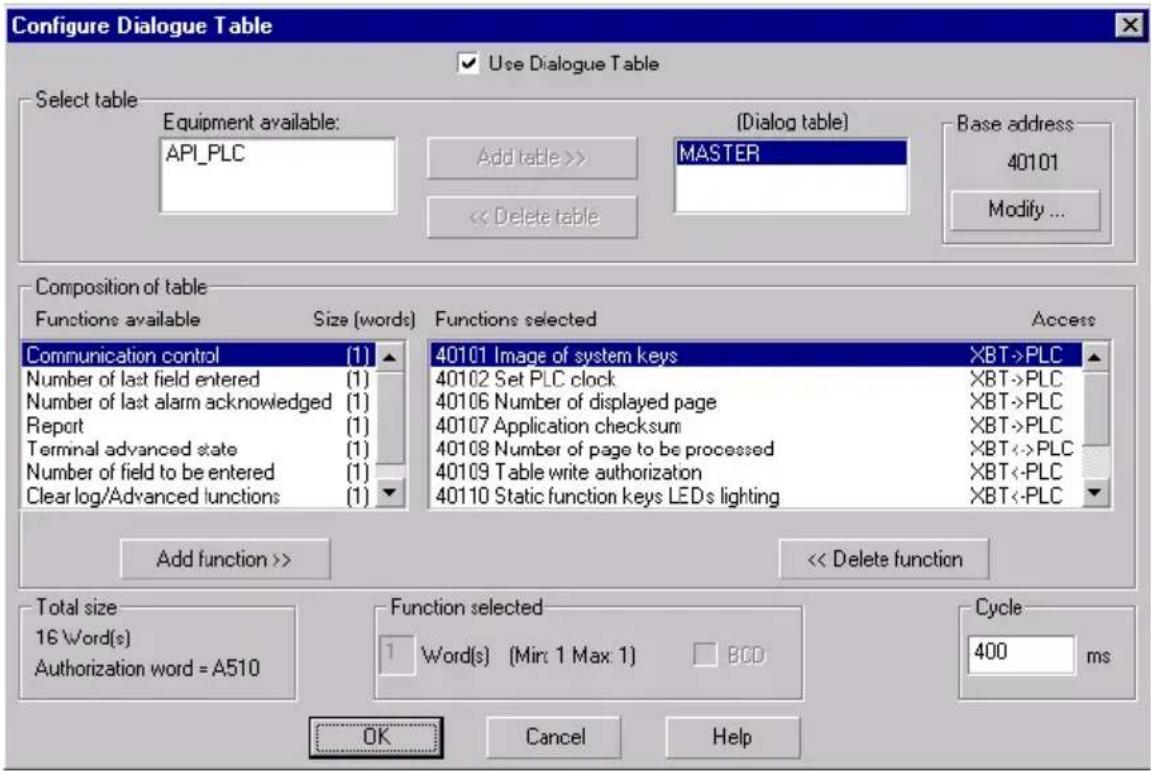
NOTE: To use the dialog table, check the "Use dialog table" box
Use Dialogue Table
| XBT ref.XBT ref. Note | |
| / | / |
4. Dialog table
To use a dialog table or an alarm table, the designer specifies the symbol for the equipment in which it will be located, as well as the basic address from which it starts.
NOTE: Before starting to program the PLC, check that all the words needed for operation of the application are included in the dialog table. In order for words to be added to the dialog table, the PLC program controlling the application must be modified.
| XBT ref. Note | |
| / | / |
Introduction
The purpose of simulation is to test operation of the application (including display of Chinese characters if the application contains any) in the XBT L100•, and thus enable the designer to validate his application without needing to transfer it to the display unit or connect up the PLC. Only one simulation can be launched at a time.
Click on Application Simulation in the Simulation menu to open two windows:
- One window representing the display unit front panel - One PLC simulation window containing three tabs:
- Page Variables
- Alarms
- Dialog Table
NOTE: Application transfer and printing are not simulated.
■ Display-unit simulation window
This window represents the display front panel. It therefore contains a graphic representation of each of the keypad keys and a zone representing the screen where the pages are displayed as they appear on the terminal in running mode. Access to every key of the display unit keypad is possible using the mouse or a key on the PC keypad.
| XBT ref. Note | |
| / | / |
5. Simulation
■ Keypad keys during simulation

This window does not have a menu, its size cannot be modified, nor can it be closed (it is closed at the same time as the PLC simulation window). Use [Alt] + [6] (numeric keypad) on the front panel, and click on L1000. The simulation changes to priority display.
C
PLC simulation window
This window contains four tabs.
■ "Page Variables" tab
This tab contains a grid consisting of 3 columns:
- The first column called "Equipment" contains the symbol for the equipment associated with the variable.
- A second column called "Reference" contains the variable address, and the syntax used therefore depends on the protocol selected.
- A third column called "Value" contains the current variable value (non-signed decimal and ascending order obligatory).
| XBT ref. Note | |
| N200 No alarm management | |
5. Simulation
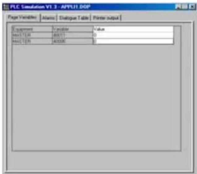
There is one line for each variable used in the page being displayed. If the same variable is used several times in the page, it only appears once in the grid.
It is possible to change the value of a variable by entering a new value in the box corresponding to the average of the PC keypad. Write-only fields do not appear until the display unit has entered an input.
"Alarms" tab
The grid representing the table of word bits used is similar to that used to create alarms. In addition, the only active boxes are those corresponding to the bits on which alarms have been defined. These boxes display the value of the corresponding bit (- or x), and double-clicking on one of these boxes simulates the change of state of the alarm bit.
| XBT ref. Note | |
| N200 No alarm management | |
5. Simulation
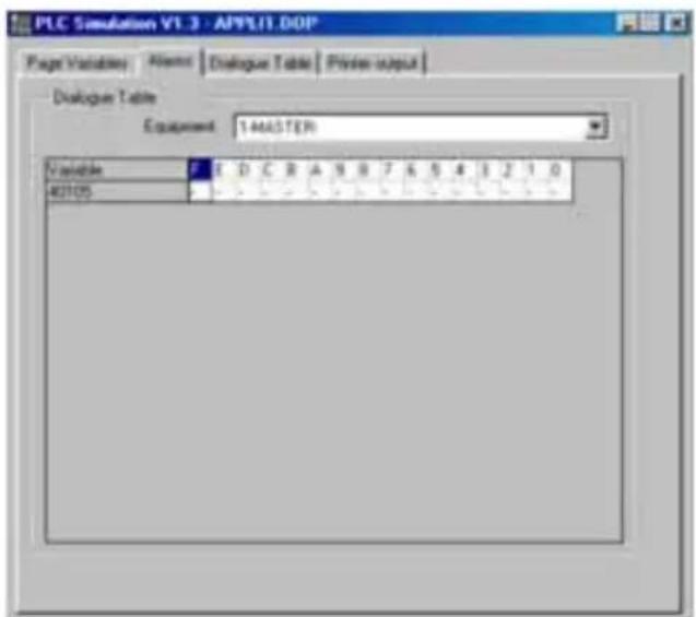
"Dialog Table" tab
The dialog-table simulation window represents the list of words used.
The value of these words can be modified.
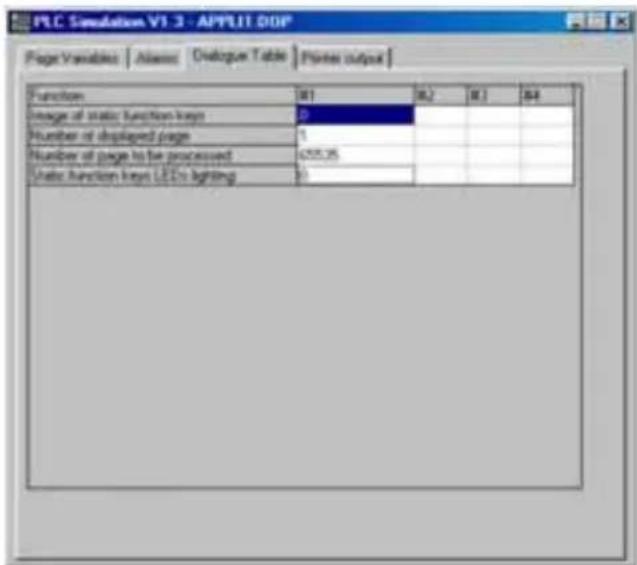
| XBT ref. Note | |
| N200 No alarm management | |
5. Simulation
■ "Printer Output" tab
This tab is used to display the print format for the display unit.
| XBT ref. Note | |
| N200/N400/N410NU400R400/R410 | No printer link |
6. Transferring an application
Connecting the display unit
For transfers, the link between the display unit and the PC uses either an RS232C serial cable or a USB cable.
For more information about connections, see chapter A, section Connection, Page 11.

WARNING
ELECTRICAL CONNECTIONS
- Disconnect the power supply before connecting the serial link.
- Only connect one type of serial link at a time.
- Tighten both connector fixing screws.
Failure to follow this instruction can result in death, serious injury, or equipment damage.
Starting up the display unit
Refer to the quick reference guide supplied with the product.
- Importing an application
An application is imported by selecting Import from the Transfer menu. Data is imported into a new application, not into the current application. Importing begins with checking the import protection (see section Step 2 - Configure the terminal parameters, Page 15).
Next, the XBT L100•/Connected display unit communication protocols are checked.
The import operation takes place after the checking phase.
| XBT ref. Note | |
| / | / |
6. Transferring an application
- Exporting an application
An application is exported by selecting Export from the Transfer menu. The compatibility of the connected equipment and the transferred application is checked.
| XBT ref. Note | |
| / | / |
7. Description of dialog-table words
The number of words in the table depends on the choice of status data and commands you wish to process during dialog (see section 4. Dialog table, Page 53).
Similarly, the number of words available depends on the type of display unit (function keys present or not for example).
The description below gives the content of the various words in the dialog table:
| Size Functions Exchange Page | |||
| 1 word | Image of static function keys | XBT -> PLC | C67 |
| 1 word Image of system keys XBT -> PLC C67 | |||
| 1 word Image of numeric keys XBT -> PLC C67 | |||
| 1 word | Communication monitoring | XBT -> PLC | C68 |
| 4 words Set PLC clock XBT -> PLC C69 | |||
| 1 word Number of page displayed XBT -> PLC C70 | |||
| 1 word | Number of last completed field | XBT -> PLC | C70 |
| 1 word | Number of last acknowledged alarm | XBT -> PLC C71 | |
| 1 word | Report | XBT -> PLC | C71 |
| 1 word | Log fill level | XBT -> PLC | C72 |
| 1 word Application checksum XBT -> PLC C72 | |||
| 1 word | Terminal advanced status | XBT -> PLC | C73 |
| 1 word | Number of page to be processed | XBT<->PLC C74 | |
| 1 word | Number of field to be completed | XBT<->PLC C75 | |
| XBT ref. | Note |
| / | / |
7. Description of dialog-table words
| Size Functions Exchange Page | |||
| 1 word Print command XBT<->PLC C77 | |||
| 1 word | Write table authorization | XBT <- PLC | C78 |
| 1 word | Clear log/Advanced functions | XBT <- PLC | C78 |
| 1 word Static function keys on XBT <- PLC | C81 | ||
| 1 word | Lock static function keys | XBT <- PLC | C82 |
| 1 word System key locking XBT <- PLC C82 | |||
| 1 word Numeric key locking XBT <- PLC C82 | |||
| 1 word Terminal language XBT <- PLC C83 | |||
| 16 words | Alarm table | XBT <- PLC | C84 |
| 4 words | Set terminal clock | XBT <- PLC | C85 |
PLC: programmable logic controller
The "->","<->" or "<-" arrows specify the direction in which information is traveling.
XBT -> PLC: Writing by the display unit of one or more words to the equipment selected for the dialog table.
XBT <-> PLC: Writing by the display unit of one or more words to the equipment selected for the dialog table, then writing of a report.
XBT <- PLC: Reading by the display unit of one or more words in the equipment selected for the dialog table.
| XBT ref. | Note |
| / | / |
7. Description of dialog-table words
Detailed description
Images of static/system/numeric function keys
Bit at 1 = key pressed (impulse command).
Bit at 1 = key press memorized (toggle command).
| Static function keys | System keys Numeric keys | |||
| Bit | Image of Bit Image of Bit Image of | |||
| 0 F1 0 0 0 |  | |||
| 1 F2 1 1 1 |  | |||
| 2 F3 2 2 2 |  | |||
| 3 F4 3 3 3 |  | |||
| 4 F5 4 4 4 |  | |||
| 5 F6 5 reserved (0) 5 5 | ||||
| 6 F7 6 reserved (0) 6 6 | ||||
| 7 F8 7 reserved (0) 7 7 | ||||
| 8 F9 8 reserved (0) 8 8 | ||||
| 9 F10 9 9 9 |  | |||
| 10 F11 10 reserved (0) 10 +/- | ||||
| 11 F12 11 reserved (0) 11 . | ||||
| 12 reserved (0) 12 reserved (0) 12 |  | |||
| 13 | reserved (0) | 13 |  | 13 reserved (0) |
| 14 | reserved (0) | 14 | reserved (0) | 14 reserved (0) |
| 15 reserved (0) 15 | global (1) | 15 | reserved (0) | |
Reserved (0): (0) specifies that the bit remains at 0
| XBT ref. | Note |
| N200/N400/N401/N410NU400R400/R410/R411 | (1) This bit at 1 means that a key has been pressed.Management of this bit is independent of key locking. |
7. Description of dialog-table words
■ Communication monitoring
This word is incremented every dialog-table write cycle. When it reaches 65535 it does not pass through 0, but immediately takes the value 1.
XBT -> PLC Communication monitoring
The word can be used as a watchdog for the display unit: If it is not incremented regularly, it can be assumed that the display unit is no longer operational. Finally, this word can take the value 0 when the display unit is powered up and whenever communication is restarted, but never takes the value 0 thereafter: It can therefore be used by the synchronization pilot equipment to detect starting up of a display unit or restarting communication.
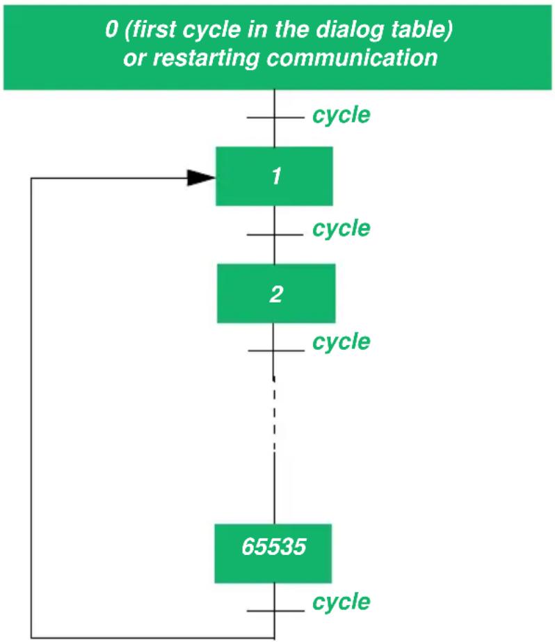
flowchart
graph TD
    A["0 (first cycle in the dialog table) or restarting communication"] --> B["cycle"]
    B --> C["1"]
    C --> D["cycle"]
    D --> E["2"]
    E --> F["cycle"]
    F --> G["65535"]
    G --> H["cycle"]
| XBT ref. Note | |
| / | / |

WARNING
LOSS OF CONTROL
- Loss of communication between the display unit and the PLC can result in partial or complete loss of control of the machine.
- Check the display unit
- Check the "Communication monitoring" word in the dialog table via the PLC program.
Failure to follow this instruction can result in death, serious injury, or equipment damage.
Set PLC clock
This set of words, each divided into 2 bytes, tells the control system the display-unit time at each cycle so that, if necessary, its internal real-time clock can be updated.
| XBT -> PLC Seconds Day of the week | |
| XBT -> PLC Hours Minutes | |
| XBT -> PLC Month Day | |
| XBT -> PLC Century Year | |
| Bit 15 87 0 | |
The day of the week is encoded as follows:
| 1 Monday |
| 2 Tuesday |
| 3 Wednesday |
| 4 Thursday |
| 5 Friday |
| 6 Saturday |
| 7 Sunday |
How the various bytes are entered can be selected in the XBT L100-configuration software: Either BCD format (in which case if it is fifteen hours, the content of the Hour field will be 0x15) or Standard format (in which case if it is fifteen hours, the content of the Hour field will be 0x0F) can be selected. The choice of BCD/Standard applies to all four words, and cannot be made independently for each byte.
| XBT ref. Note | |
| / | / |
7. Description of dialog-table words
Note that to simplify time-setting management in the pilot equipment, a status-word bit is assigned to this function.
| XBT -> PLC | Report | ||||||||||||||
| Bit 15 13 0 | |||||||||||||||
Bit 13 changes to 1 in cases where the operator updates the time on the terminal.
■ Number of page displayed
This word contains the number of the page displayed on the terminal. The code of the page displayed follows the same rules as those which apply to the "Number of page to be processed" word, and in addition the following rule exists: the "Number of page displayed" word equals 0xFFFF in the following cases:
- When the display unit displays an alarm ^(1)
- When the display unit is in the processing of changing page
XBT -> PLC Number of page displayed
Recommended method of displaying a page (see chapter C, section Number of page to be processed, Page 74)
■ Number of last completed field
This word contains the number of the last completed field. A field is considered to have been completed when it has been confirmed with ENTER, or as soon as the associated PLC value has been modified by the user (as is the case when the field is in immediate-write mode). The field number is available in XBT L100•, via the Display/Field Numbers menu.
XBT -> PLC Number of last completed field
Recommended method of displaying a page (see section Number of field to be completed, Page 75)
| XBT ref. Note | |
| N200 | (1) No alarm management |
7. Description of dialog-table words
■ Number of last acknowledged alarm ^(1)
When the user acknowledges an alarm (by pressing the key on the display unit), the display unit sends the acknowledgment number to the equipment, which generated the alarm. This number is valid during one cycle of the dialog table, then it returns to -1. This alarm number is stored in a 16-bit word. This number is the significance of the bit associated with the alarm in its alarm table (see table below).
| XBT -> PLC | Number of last acknowledged alarm |
This word is used bit by bit. Each bit has a precise meaning (see the paragraph on the corresponding word for a detailed description of the function associated with each bit).
| XBT -> PLC | Report | |||||||||||||||
| Bit | 15 | |||||||||||||||
| Bit no. | Bit name |
| 0 | CONFIDENTIAL_MODE |
| 1 | reserved (0) |
| 2 | END_OF_ENTRY_ON_ENTER |
| 3 | END_OF_ENTRY_ON_ESC |
| 4 | END_OF_ENTRY_ON_TIMEOUT |
| XBT ref. | Note |
| N200 | (1) No alarm management |
| Bit no. Bit name |
| 5 PRINTING_IN_PROGRESS |
| 6 PRINTING_FAULT |
| 7 PRINTING_STOPPED |
| 8 reserved (0) |
| 9 reserved (0) |
| 10 reserved (0) |
| 11 LOW_CURRENT_LANGUAGE_NUMBER |
| 12 HIGH_CURRENT_LANGUAGE_NUMBER |
| 13 NEW_TIME_PROVIDED_BY_OPERATOR |
| 14 reserved (0) |
| 15 reserved (0) |
Log fill level
This word uses 2 bytes. The most-significant byte is reserved and is written to the value 0 by the terminal on each cycle of the dialog table. The least-significant byte contains a number between 0 and 100, which indicates how much of the log is in use as a percentage.
| XBT -> PLC Reserved (0) Log fill level |
NOTE: The log fill level is zero if the log is empty. The fill level is 100 if and only if the log is completely full.
Application checksum
This word contains a checksum denoting the version of a dialog application. It is only found in the dialog table. The PLC can thus monitor that the dialog application is the correct one.
| XBT -> PLC Application identification |
| XBT ref. Note | |
| N200/N400/N410NU400 | No checksum |
7. Description of dialog-table words
■ Terminal advanced state
This word is used split into two bytes, the first of which is reserved and the second used bit by bit.
| XBT -> PLC | ||||||||||||||
| R | e | s | e | r | v | e | d | e | q | u | a | l | s | |
| Bit 15 | 87 | 2 | 1 | 0 | ||||||||||
Current password level:
These three least-significant bits (0 to 2) in the lower byte contain information relating to the current display-unit password. Each bit is at 1 if the associated password is selected, and each bit is at 0 if the associated password is not selected.
| XBT -> PLC | Report |
Bit 15 0
The advantage of this word is as follows: It enables the display-unit password to be used as the password for the PLC (enabling, for example, the whole process to be switched to a certain state, for example maintenance, by means of the display unit, by entering the ad hoc password: The display unit can then access pages shared by a maintenance password, and the PLC can thus know that the display unit is in maintenance mode, enabling it in turn to switch to a mode where it is ready to accept modifications).
It should be noted that for reasons of compatibility with existing PLC applications, there is also a bit in the "Report" word (the CONFIDENTIAL_MODE bit), which is at 1 as soon as at least one password has been confirmed.
| XBT ref. Note | |
| / | / |
7. Description of dialog-table words
■ Number of page to be processed
This 16-bit word contains the number of the page to be displayed. The content of this word should follow the rule below:
| Content (N) Meaning | |
| 1 to 64999 | Display of the application page whose number is requested (N) |
| 65420 to 65519 | Display of the system page whose number is:In signed decimal: (-16-N)In non-signed decimal: (65520-N)In hexadecimal: (FFF0-N) |

If the control system wishes to display page 45, it writes 45 to this word. If it wishes to display system page 2, it writes 65520-2=65518 to this word.
XBT<->PLC Number of page to be processed
Recommended method of displaying a page:
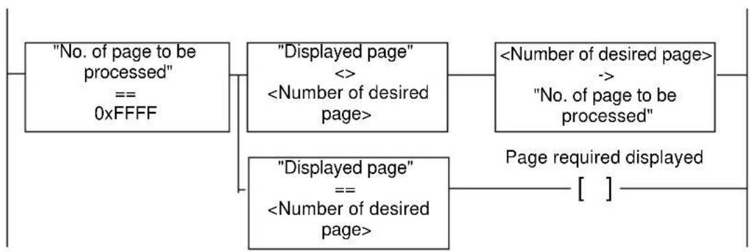
flowchart
graph TD
A["No. of page to be processed"<br>== 0xFFFF"] --> B["Displayed page"<br><><br><Number of desired page>"]
B --> C["<Number of desired page>"]
C --> D["No. of page to be processed"]
D --> E[""Page required displayed [ "]"]
E --> F["Displayed page"<br>==<br><Number of desired page>"]
| XBT ref. Note | |
| / | / |
7. Description of dialog-table words
■ Number of field to be completed
This 16-bit word contains the number of the field to be completed. The content of this word should follow the rule below:
| Content Meaning | |
| 1 to 50 | Change to input mode of the field in the current application page whose number is the requested value. |

If the control system wishes field 37 to switch to input mode, it writes 37 to this word.
XBT<->PLC Number of field to be completed
C
| XBT ref. Note | |
| / | / |
7. Description of dialog-table words
Recommended method of controlling a field input:
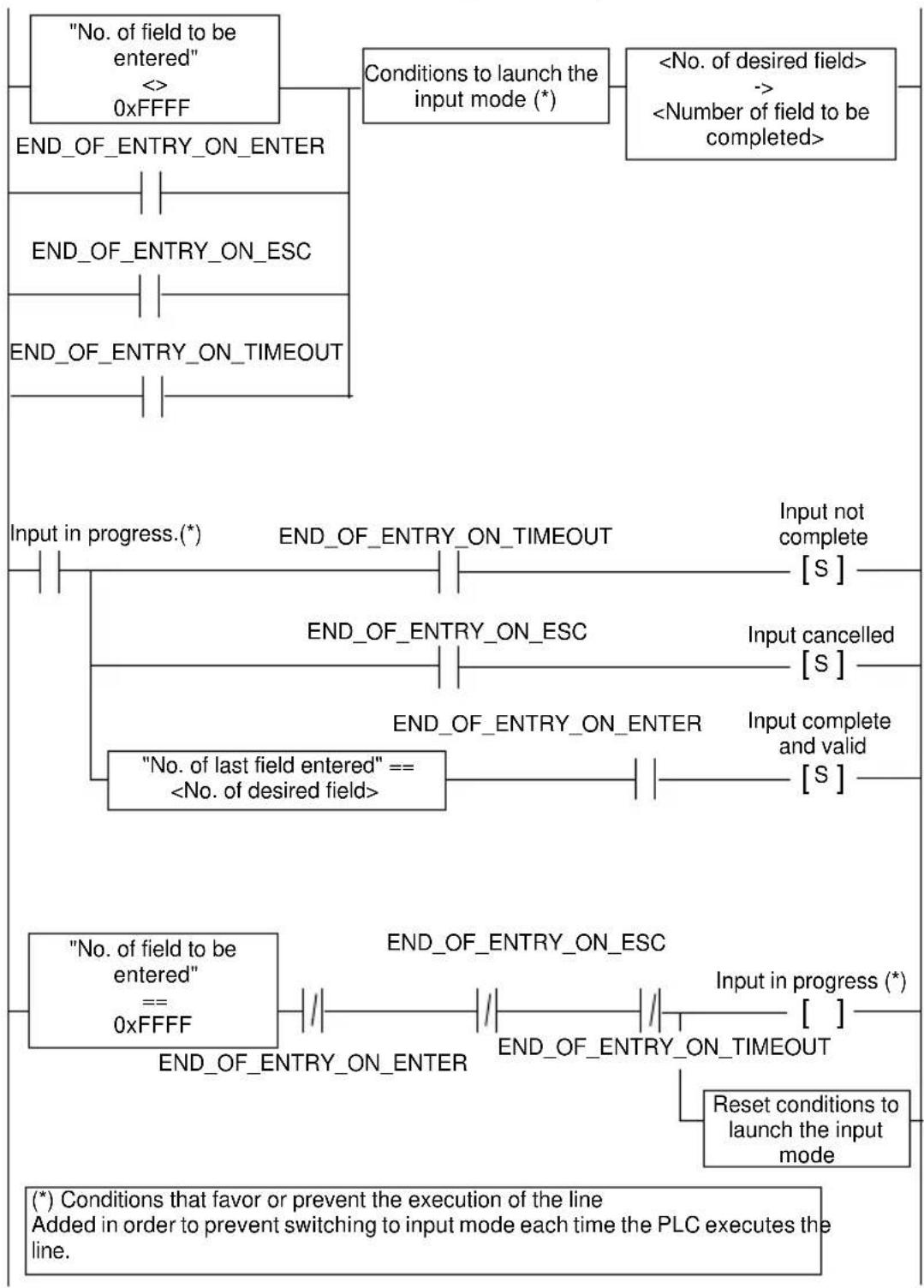
flowchart
graph TD
    A["No. of field to be entered"] --> B["0xFFFF"]
    B --> C["END_OF_ENTRY_ON_ENTER"]
    C --> D["END_OF_ENTRY_ON_ESC"]
    D --> E["END_OF_ENTRY_ON_TIMEOUT"]
    F["No. of last field entered"] --> G["== <No. of desired field>"]
    H["END_OF_ENTRY_ON_TIMEOUT"] --> I["Input not complete [S"]]
    J["END_OF_ENTRY_ON_ESC"] --> K["Input cancelled [S"]]
    L["END_OF_ENTRY_ON_ENTER"] --> M["Input complete and valid [S"]]
    N["END_OF_ENTRY_ON_OUT"] --> O["Reset conditions to launch the input mode"]
    P["END_OF_ENTRY_ON_ENTER"] --> Q["END_OF_ENTRY_ON_OUT"]
    R["END_OF_ENTRY_ON_ESC"] --> S["Input in progress (*)"]
    T["No. of field to be entered"] --> U["== 0xFFFF"]
    V["No. of field to be entered"] --> W["== 0xFFFF"]
    X["No. of desired field"] --> Y["Input not complete [S"]]
    Z["No. of desired field"] --> AA["Input cancelled [S"]]
    AB["No. of desired field"] --> AC["Input complete and valid [S"]]
    AD["No. of desired field"] --> AE["Input not complete [S"]]
    AF["No. of desired field"] --> AG["Input not complete [S"]]
    AH["No. of desired field"] --> AI["Input not complete [S"]]
    AJ["No. of desired field"] --> AK["Input not complete [S"]]
    AL["No. of desired field"] --> AM["Input not complete [S"]]
    AN["No. of desired field"] --> AO["Input not complete [S"]]
    AP["No. of desired field"] --> AQ["Input not complete [S"]]
    AR["No. of desired field"] --> AS["Input not complete [S"]]
    AT["No. of desired field"] --> AU["Input not complete [S"]]
    AV["No. of desired field"] --> AW["Input not complete [S"]]
    AX["No. of desired field"] --> AY["Input not complete [S"]]
| XBT ref. Note | |
| / | / |
7. Description of dialog-table words
| XBT -> PLC | Report |
Bit 154320
- Bit 2: END_OF_ENTRY_ON_ENTER: Set to 1 once the operator has confirmed completion of the field by pressing ENTER.
- Bit 3: END_OF_ENTRY_ON_ESC: Set to 1 once the operator has cancelled completion of the field by pressing ESC.
- Bit 4: END_OF_ENTRY_ON_TIMEOUT: Set to 1 if the operator neither confirms nor cancels completion of the field within one minute.
Print command
This 16-bit word is split into two bytes: The most-significant byte defines which print function to use and the least-significant byte is used to switch from the parameters to the selected print function.
XBT<->PLC Print function code Function data
The list of function codes and parameters supported is as follows:
| MSB LSB Function | ||
| 0x02 Any | Print the alarm | log |
Once the terminal has taken account of the request (this does not mean that printing has finished), it writes 0xFFFF to this word.
You will notice that there are several bits dedicated to printing in the status word: These bits are PRINTING_IN_PROGRESS, PRINTING_FAULT AND PRINTING_STOPPED.
| XBT -> PLC | Report |
Bit 15 7 6 5
0
| XBT ref. | Note |
| N200/N400/N410NU400R400/R410 | No printer link |
7. Description of dialog-table words
Write table authorization
This word consists of two parts: The 8 most-significant bits should contain the value 0xA5, whereas the 8 least-significant bits should contain the number of words in the dialog table, in hexadecimal notation (hence, if the dialog table contains 12 words, the value of the 8 least-significant bits will be 0x0C, for example 16#A50C).
| XBT <- PLC 0xA5 No. of words in the dialog table | ||
| Bit 15 | 8 7 | 0 |
This word is a safety measure for the pilot device and for the display unit: Unless this word has the expected value, the display unit will refrain from writing anything to the pilot device memory, and conversely, will refrain from interpreting the command words it might find in the dialog table. The message "INCORRECT AUTHORIZATION TABLE" is displayed intermittently until the word is correct.
Note that there is no possible validity check for an alarm table not located in the pilot device.
Clear log/Advanced functions
This 16-bit word is split into two bytes: The most-significant byte is used to define the function required of the display unit by the pilot device, and the least-significant byte is used to switch the parameters to the function called by the most-significant byte.
| XBT<-PLC | Function code | Function data | |
| Bit 15 | 87 | 0 |
| XBT ref. Note | |
| N200 No alarm management | |
| N200/N400/N410NU400R400/R410 | No choice of backlight color |
7. Description of dialog-table words
The list of function codes and parameters supported are as follows:
| Function Parameter | ||
| 0 Clear the alarm log 0xFF | ||
| 1 Forces the backlight color | 0 to 4(XBT N401/R411) | |
| 2 | Forces the display unit password level | 0 to 7 |
In cases where the pilot device might send the display unit a command:
- That is unspecified
- With incorrect parameters
the display unit simply ignores the command.
For function 0, the pilot device can check that the request has been recognized by examining the value of the "Log fill level" word.
For function 2, the pilot device has a check to ensure acknowledgment of its request via the “Terminal advanced status” word in the write cycle of the DT following its request.
Function 0:
This function has only one parameter value: 0xFF. When the PLC writes 0x00FF to the “Clear log” word, the terminal clears the associated alarm log. As long as the PLC retains the value 0x00FF, the log is not cleared again. To repeat a clear instruction, a neutral value must be written to the word (for example 0x0000) and then 0x00FF written again.
Function 1:
The backlight colors are defined as follows:
| Color Function parameters (LSB) | |
| Unchanged 0 | |
| Red 1 | |
| Green 2 | |
| Orange 3 | |
| No backlight 4 | |
| XBT ref. Note | |
| N200 No alarm management | |
| N200/N400/N410NU400R400/R410 | No choice of backlight color |
7. Description of dialog-table words
If the dialog table has not imposed a backlight color (because this function has never been called since the application started) or if the dialog table has asked for the backlight color not to be forced (by writing the value 0x0100 to the "Advanced functions" word) then the backlight color is that imposed by the page displayed.
Function 2:
The password is defined as follows:
| 0 | 0 | 0 | 0 | 0 | C | B | A |
| 7 | 0 | ||||||
| Password Function parameters (LSB) | |
| Unchanged/Reinitialization 0 | |
| A selected 1 | |
| B selected 2 | |
| B+A selected 3 | |
| C selected 4 | |
| C+A selected 5 | |
| C+B selected 6 | |
| C+B+A selected 7 | |
If the dialog table has not imposed a password (because this function has never been called since the application started) or if the dialog table is not imposing a password (by writing the value 0x0200 to the "Advanced functions" word) then the password level is that defined by the display unit user.
Conversely, if the dialog table has asked at least once for the password to be either A+B (via the value 0x0203) then whatever the password requested by the user, the password level will be A+B, that imposed by the dialog table (same logic as for other passwords).
| XBT ref. Note | |
| N200/N400/N410NU400R400/R410 | No choice of backlight color |
7. Description of dialog-table words
■ Static function keys on
This word is used bit by bit, with each bit number i representing the state of the diode associated with the static function key Fi+1.
XBT <- PLC Control of indicator lights
| Bit Role Control Mode | |
| 0 (1) On/Off (0) F1 key | |
| 1 (1) On/Off (0) F2 key | |
| 2 (1) On/Off (0) F3 key | |
| 3 (1) On/Off (0) F4 key | |
| 4 (1) On/Off (0) F5 key | |
| 5 (1) On/Off (0) F6 key | |
| 6 (1) On/Off (0) F7 key | |
| 7 (1) On/Off (0) F8 key | |
| 8 (1) On/Off (0) F9 key | |
| 9 (1) On/Off (0) F10 key | |
| 10 (1) On/Off (0) F11 key | |
| 11 (1) On/Off (0) F12 key | |
| 12 reserved (0) | |
| 13 reserved (0) | |
| 14 reserved (0) | |
| 15 reserved (0) | |
| XBT ref. Note | |
| N200/N400/N410NU400R400/R410 | No indicator lights |
| N401 For display units in “control” mode only | |
7. Description of dialog-table words
■ Locking static/system/numeric function keys
Each key on the display unit can be locked by the PLC. The dialog table enables dialog between the PLC and the display unit.
Bit at 1 = key pressed (impulse command).
Bit at 1 = key press memorized (toggle command).
| SFK System keys | Numeric keys | ||||
| Bit | Locking of Bit Locking of Bit | Locking of | |||
| 0 F1 0 0 0 |  | ||||
| 1 F2 1 1 1 |  | ||||
| 2 F3 2 2 2 |  | ||||
| 3 F4 3 3 3 |  | ||||
| 4 F5 4 4 4 |  | ||||
| 5 F6 5 reserved (0) 5 5 | |||||
| 6 F7 6 reserved (0) 6 6 | |||||
| 7 F8 7 reserved (0) 7 7 | |||||
| 8 F9 8 reserved (0) 8 8 | |||||
| 9 F10 9 9 9 |  | ||||
| 10 | F11 | 10 | reserved (0) | 10 | . |
| 11 | F12 | 11 | reserved (0) | 11 | +/- |
| 12 | reserved (0) | 12 | reserved (0) | 12 |  |
| 13 | reserved (0) | 13 |  | 13 | reserved (0) |
| 14 | reserved (0) | 14 | reserved (0) | 14 | reserved (0) |
| 15 | reserved (0) | 15 | global (1) | 15 | reserved (0) |
| XBT ref. | Note |
| N200/N400/N401/N410NU400R400/R410/R411 | (1) This bit is used to lock the whole keypad |
7. Description of dialog-table words
When a key is locked, it can no longer have any effect at application program level: Thus, for example, if the user has locked the key, the operator will not be able to confirm an input
using

Terminal language
This word forces the display unit to use language number N, where N is a language number defined in XBT L100•.
XBT <- PLC Display-unit language
This word can take the following values:
| Value Effect | |
| 0 The dialog table does not force any language | |
| 1 to N Language number, as defined in the application | |
| Other values | No effect: The display unit remains in the state it was in before this command was applied |
As long as this word equals 0x0000, any request to change the language on the part of the user will be accepted. However, as soon as a correct language number is imposed via the dialog table, the user can no longer modify the display unit language.
Note that for reasons of compatibility with existing PLC applications, there are also two bits in the report word:
- Bit 11: LOW_CURRENT_LANGUAGE_NUMBER (LCLN)
- Bit 12: HIGH_CURRENT_LANGUAGE_NUMBER (HCLN)
serving a dual purpose with this byte.
| XBT ref. Note | |
| / | / |
7. Description of dialog-table words
These bits can be combined as follows:
| HNLC LNLC Language | ||
| 0 | 0 | No. 1 |
| 0 | 1 | No. 2 |
| 1 | 0 | No. 3 |
| 1 | 1 | Other |
| XBT -> PLC | Report |
Bit 15 12 11 0
Alarm table (1)
There can be up to 256 alarms on the display unit, and these 256 alarms can be divided between several alarm tables located in the various devices (up to 15). The distribution granularity of these 256 alarms within the various alarm tables is 16 bits (the size of a word).
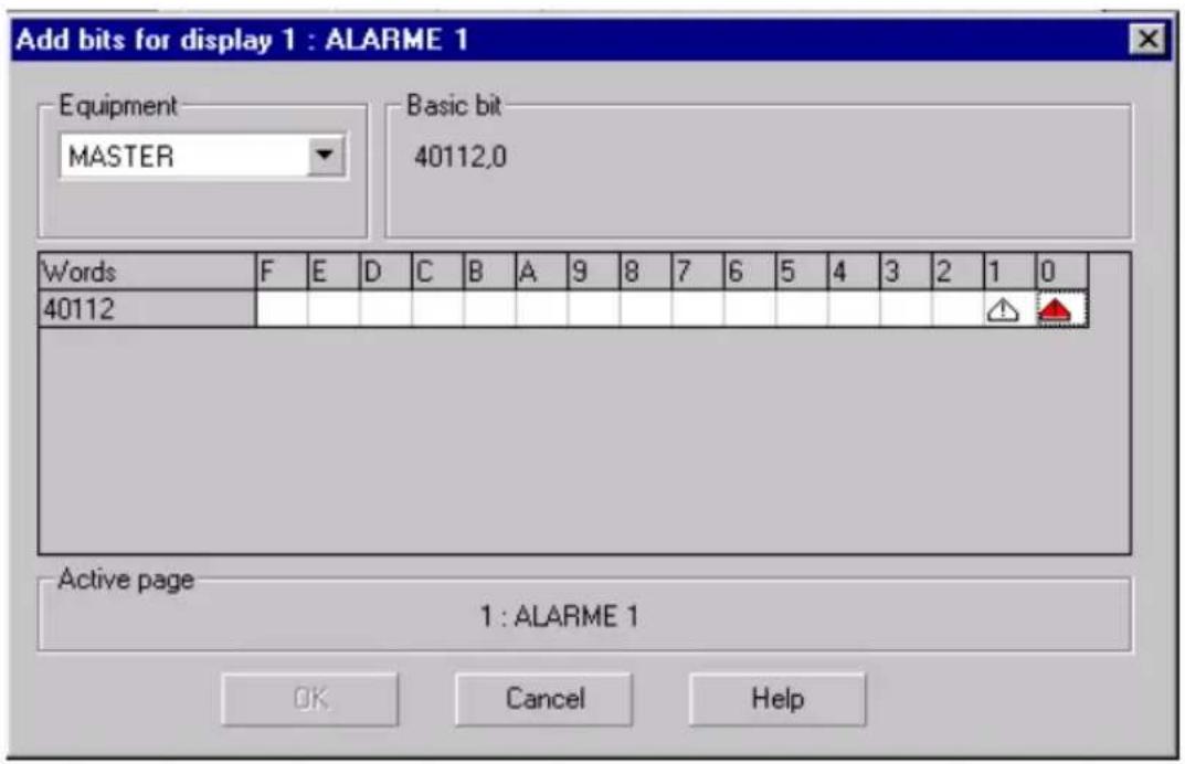
| XBT ref. Note | |
| N200 (1) No alarm management | |
7. Description of dialog-table words
Depending on the type of display unit, more or fewer alarms may be permitted. Nevertheless, the structure of a word used to signal alarms is always as follows: One 16-bit word, where each bit represents an alarm.
XBT <- PLC Alarm
When several alarm words are positioned in a device, the alarms are numbered bit by bit, starting with the least-significant bit in the lowest order address (bearing the number 1) and ascending towards the most-significant bit and the highest-order address:
| No.of bit | 76543210 | |||||||
| Alarm Page No. | #8 | #7 | #6 | #5 | #4 | #3 | #2 | #1 |
| #24 # | 23 #22 | #21 #20 | #19 # | 18 #17 | ||||
| ... ... | ... ... ... | ... ... ... | ||||||
| #248 | #247 #2 | 46 #245 | #244 | #243 #2 | 42 #241 | |||
When several alarm words are defined in a given device, these words are always located in consecutive addresses: There cannot be a gap between alarm numbers.
Set terminal clock
This set of 16-bit words, each divided into 2 bytes, enables the control system to update the display unit real-time clock.
| XBT <- PLC | Seconds | Day of the week |
| XBT <- PLC | Hours | Minutes |
| XBT <- PLC | Month | Day |
| XBT <- PLC | Century | Year |
| XBT ref. | Note |
| / | / |
7. Description of dialog-table words
How the various bytes are entered can be selected in the XBT L100-configuration software: Either BCD format (in which case if it is fifteen hours, the content of the Hour field will be 0x15) or Standard format (in which case if it is fifteen hours, the content of the Hour field will be 0x0F) can be selected.
The choice of BCD/Standard applies to all these four words, and cannot be made independently for each byte. The “Day of the week” field is not used by the display unit: The latter automatically calculates the right day associated with a given date. Irrespective of the content of the “Day of the week” field, the display unit ignores it.
| XBT ref. Note | |
| / | / |
Chapter D
Example of a simple application
D
When creating the example, you are guided through the process, the objective being to create your first application quickly.
Chapters B and C will tell you everything you need to know about the various actions.
You are a beginner. Creating your first application:
- Application content 5
- Creation in XBT L100• 10
Step 1: Creating the application 10
Step 2: Creating the equipment 10
Step 3: Creating application pages 10
Step 4: Configuring the dialog table 19
Step 5: Creating alarm pages 20
Step 6: Configuring the display unit 21
Step 7: Saving the application 21
Step 8: Application simulation ____ 21
- Loading the application into the display unit 22
- Using the application with the display unit ____ 23
Reminder 23
Input principle 23
Input using the arrow keys 23
Deleting characters 23
Print alarms as a data stream 24
Alarm log 24
Contents
1. Application content
This application has been created for the XBT N401 display unit. It includes seven application pages and two alarm pages.
Application page 1
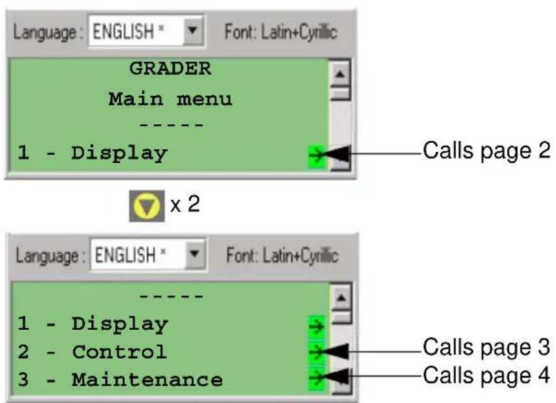
Application page 2
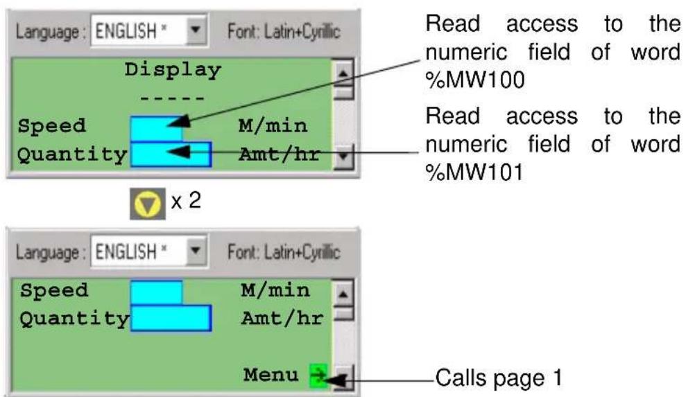
1. Application content
Application page 3
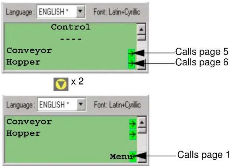
Application page 4
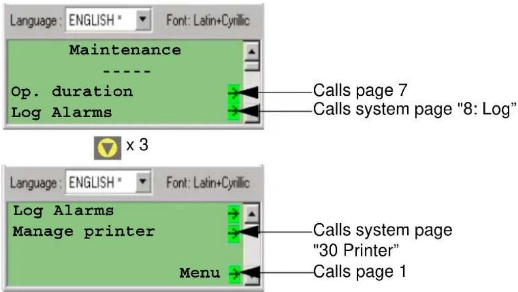
1. Application content
Application page 5
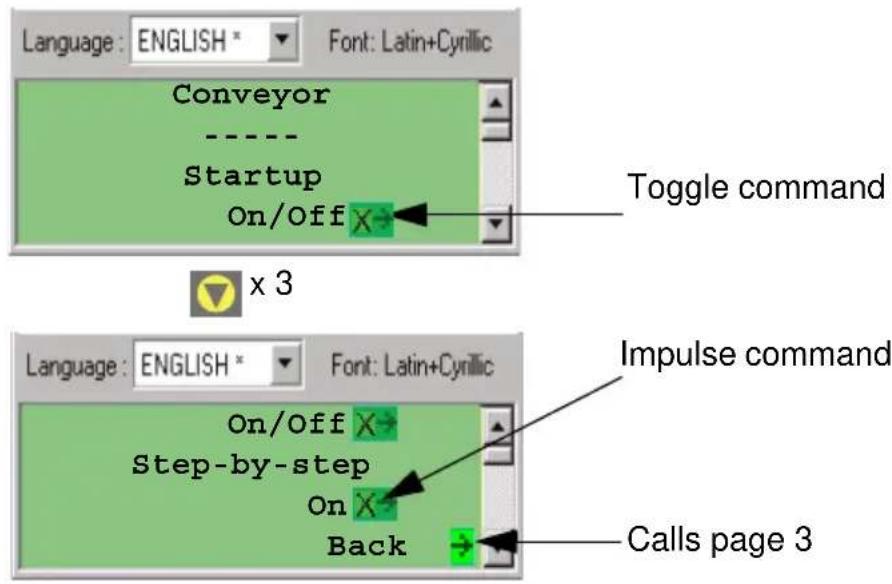
Application page 6
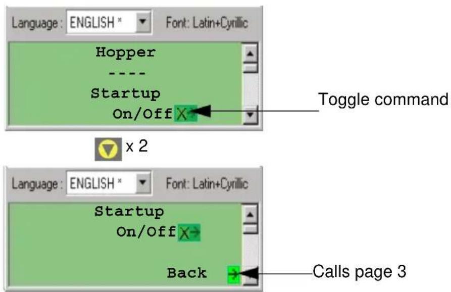
1. Application content
Application page 7
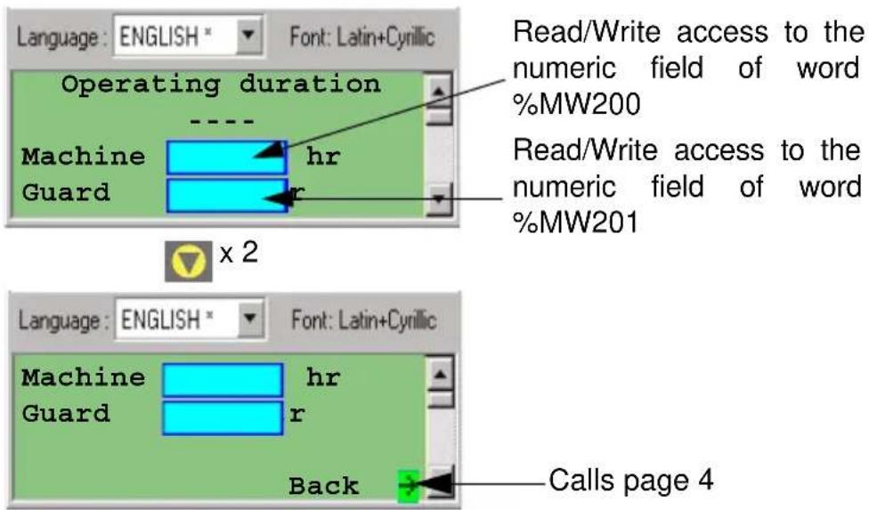
Alarm page 1
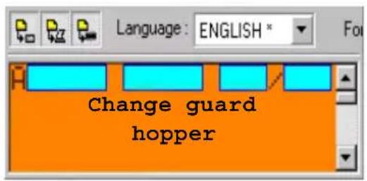
Page displayed when bit 0 of word %MW510 is at 1.
Alarm page 2
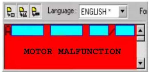
Page displayed when bit 4 of word %MW510 is at 1.
1. Application content
Page structure
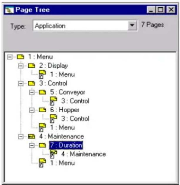
(see chapter C, section 7. Description of dialog-table words, Page 65)
The dialog table is configured with XBT L100• (see section Step 6 - Configure the dialog table, Page 24)
The list of words is as follows:
| Word Exchange | |
| Image of system keys XBT -> PLC | |
| Set PLC clock XBT -> PLC | |
| Number of page displayed XBT -> PLC | |
| Application checksum XBT -> PLC | |
| Number of page to be processed XBT<->PLC | |
| Write table authorization XBT<->PLC | |
| Terminal language XBT <- PLC | |
| Alarm table XBT <- PLC | |
| Set terminal clock XBT <- PLC |
Step 1: Creating the application
- Launch XBT L100•
- Create a new application as described in the documentation. (see chapter C, section Creating a new application, Page 13)
- In the display unit type selection window, select an input mode XBT N401 (XBT N401(2)).
- Select the Modbus protocol (you also need to check the IEC61131 box) and confirm by clicking on OK.
Step 2: Creating the equipment
- Select the Equipment Symbol command from the Configuration menu.
- Click on the Add... button.
- Enter a symbol name (e.g., API_PLC) and an address (e.g., 2).
- Confirm by clicking on OK.
Step 3: Creating application pages
- The page editor displays page 1, enter the text for this page:
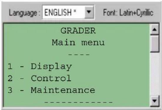
It is possible to center certain lines by selecting them and clicking on the button.
Now create the links to other pages.
First, go to the place you wish the link to appear (for example on line "1 Display".
Next, to create a link:
- Select the Insert Link command from the Edit menu (link on the right by default).
- In "Action", select "Access to application page".
- Click on the New... button.
- Confirm the default page number (2) by clicking on OK.
- Confirm by clicking on OK in the "Insert Link" page.
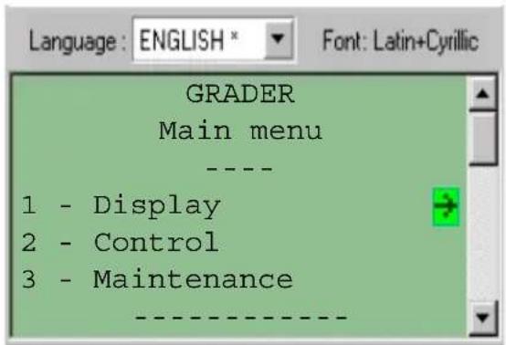
Do the same on line "2 - Control" (Page 3).
To create a link on line "3 - Maintenance":
- Select the Insert Link command from the Edit menu (link on the right by default).
- In "Action", select "Access to application page".
- Click on the New... button.
- Click on the Protection button.
- Click on the Access by password check box and then on the Access enabled A box. Keep the default password, i.e., "1111".
- Confirm by clicking on OK in the "Protection" page.
- Confirm by clicking on OK in the "New Page" page.
- Confirm by clicking on OK in the "Insert Link 3" page.
In the navigation window (see chapter C, section Navigation window, Page 9), click on "Page 2" in order to enter the content of this page.
2. Creation in XBT L100•
- The page editor displays page 2, enter the text for this page:

To create the variable field:
- Click on the icon.
- Click on Modify...
- Modify the equipment in API_PLC.
- Modify the word number by entering 100 in the "i" field.
- Confirm by clicking on OK.
- Change the field length to 3.
- Confirm the field by clicking on OK.
Enter the following lines:

To create the second variable field:
- Click on the icon.
- Click on Modify...
- Modify the equipment in API_PLC.
- Modify the word number by entering 101 in the "i" field.
- Confirm by clicking on OK.
- Confirm the field by clicking on OK.
Now create a link to go back to the main page.
To create the link:
- Select the Insert Link command from the Edit menu (link on the right by default).
- In "Action", select "Access to application page".
- In the pages, select page 1.
- Confirm by clicking on OK.
In the page navigation window, click on "Page 3" in order to enter the content of this page.
Display the "Page Tree Structure" page to follow the example.
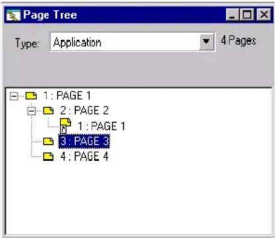
- The page editor displays page 3, enter the text for this page:
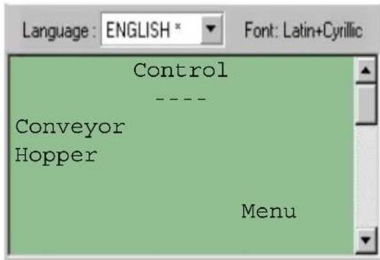
Now create the links to other pages.
- Position the cursor on the "Conveyor" line.
- Select the Insert Link command from the Edit menu (link on the right by default).
- In "Action", select "Access to application page".
- Click on the Protection button.
- Click on the "Access with password" check box.
- Click on OK to confirm the protection page.
- Click on the New... button.
- Confirm by clicking on OK in the "Insert Link L1" page.
- Confirm the default page number (5) by clicking on OK.
- Position the cursor on the "Hopper" line.
- Select the Insert Link command from the Edit menu (link on the right by default).
- In "Action", select "Access to application page".
- Click on the New... button.
- Confirm the default page number (6) by clicking on OK.
- Confirm by clicking on OK in the "Insert Link L2" page.
To create the link to return to the main menu:
- Select the Insert Link command from the Edit menu (link on the right by default).
- In "Action", select "Access to application page".
- In the pages, select page 1.
- Confirm by clicking on OK.
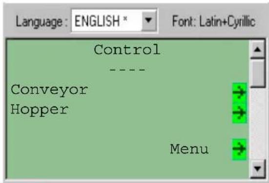
In the page navigation window, click on "Page 5" in order to enter the content of this page.
- The page editor displays page 5, enter the text for this page:
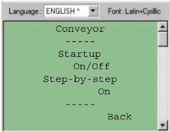
To create the link to return to the previous page:
- Select the Insert Link command from the Edit menu (link on the right by default).
- In "Action", select "Access to application page".
- In the pages, select page 3.
- Confirm by clicking on OK.
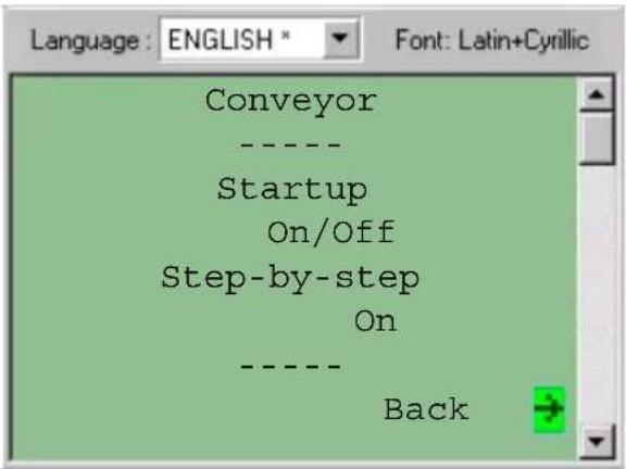
This page includes functional command links (see chapter B, section Commands sent via functional links, Page 29).
To create a functional command link for startup:
- Select the Insert Link command from the Edit menu (link on the right by default).
- In "Action", select "Toggle command".
- Click on the Modify... button.
- Modify the equipment in API_PLC.
- Modify the word number by entering 10 in the "i" field and 10 in the "j" field.
- Confirm the variable by clicking on OK.
- Confirm the "Insert Link L2" page by clicking on OK.
To create a functional command link for step-by-step mode:
- Select the Insert Link command from the Edit menu (link on the right by default).
- In "Action", select "Impulse command".
- Click on the Modify... button.
- Modify the equipment in API_PLC.
- Modify the word number by entering 15 in the "i" field and 15 in the "j" field.
- Confirm the variable by clicking on OK
- Confirm the "Insert Link L3" page by clicking on OK.
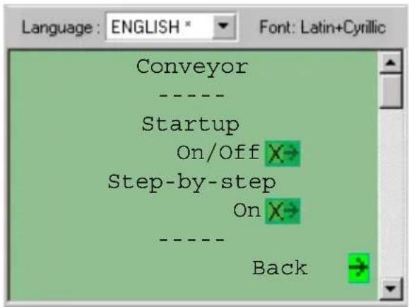
In the page navigation window, click on "Page 6" in order to enter the content of this page.
- The page editor displays page 6, enter the text for this page:
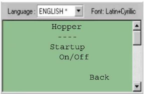
To create the link to return to the previous page:
- Select the Insert Link command from the Edit menu (link on the right by default).
- In "Action", select "Access to application page".
- In the pages, select page 3.
- Confirm by clicking on OK.
To create a functional command link for startup:
- Select the Insert Link command from the Edit menu (link on the right by default).
- In "Action", select "Toggle command".
- Click on the Modify... button.
- Modify the equipment in API_PLC.
- Modify the word number by entering 50 in the "i" field and 10 in the "j" field.
- Confirm the variable by clicking on OK.
- Confirm the "Insert Link L2" page by clicking on OK.
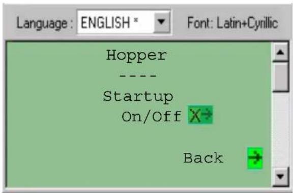
In the page navigation window, click on "Page 4" in order to enter the content of this page.
- The page editor displays page 4, enter the text for this page:
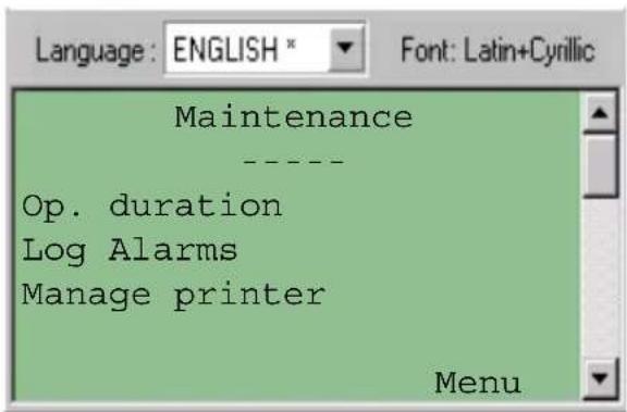
To create the links:
- Position the cursor on the "Op. duration" line.
- Select the Insert Link command from the Edit menu (link on the right by default).
- In "Action", select "Access to application page".
- Click on the New... button.
- Confirm the default page number (7) by clicking on OK.
- Confirm by clicking on OK in the "Insert Link L1" page.
The following links are links to the system pages:
- Position the cursor on the line "Log Alarms".
- Select the Insert Link command from the Edit menu (link on the right by default).
- In "Action", select "Access system page".
- In the pages, select "8: Log".
- Confirm by clicking on OK.
- Then, position the cursor on the "Manage printer" line.
-
Select the Insert Link command from the Edit menu (link on the right by default).
-
In "Action", select "Access system page".
- In the pages, select "30: Printer".
- Confirm by clicking on OK.
To create the link to return to the main menu:
- Select the Insert Link command from the Edit menu (link on the right by default).
- In "Action", select "Access to application page".
- In the pages, select page 1.
- Confirm by clicking on OK.
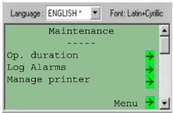
In the page navigation window, click on "Page 7" in order to enter the content of this page.
- The page editor displays page 7, enter the text for this page:
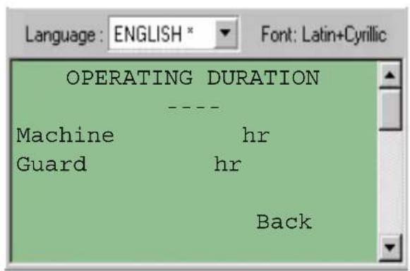
To create the first variable field:
- Click on the icon.
- Click on Modify...
- Modify the equipment in API_PLC.
- Modify the word number by entering 200 in the "i" field.
- Confirm by clicking on OK.
- Click on Options.
- In "Access", select "Read/Write".
- Click on "General".
- Change the field length to 7.
- Confirm the field by clicking on OK.
To create the second variable field:
- Click on the icon.
- Click on Modify....
- Modify the equipment in API_PLC.
- Modify the word number by entering 201 in the "i" field.
- Confirm by clicking on OK.
- Click on Options.
- In "Access", select "Read/Write".
- Click on "General".
- Change the field length to 7.
- Confirm the field by clicking on OK.
To create the link to return to the previous page:
- Select the Insert Link command from the Edit menu (link on the right by default).
- In "Action", select "Access to application page".
- In the pages, select page 4.
- Confirm by clicking on OK.
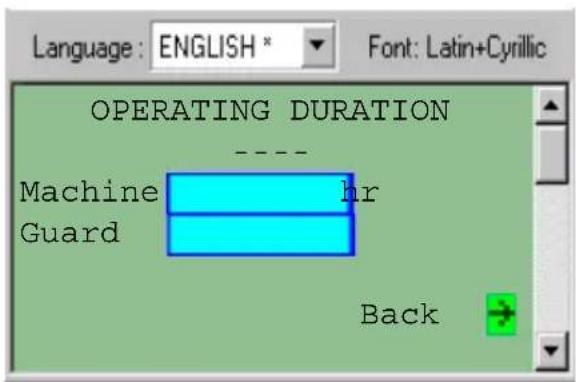
Step 4: Configuring the dialog table
To configure the dialog table
- Select the Dialog table command from the Configuration menu.
- Check the "Dialog table" box.
- Check that these functions are selected:
- Image of system keys
- Set PLC clock
- Number of page displayed
- Application checksum
- Number of page to be processed
- Write table authorization
- Terminal language
2. Creation in XBT L100•
- Alarm table
- Set terminal clock
If not, use the Delete Function or Add Function buttons to define the dialog table in accordance with the above list.
To declare the PLC dialog-table start address, click on the Modify... button in the "Base address" zone and enter 500 in the "i" field. Confirm by clicking on the OK button.
Click on OK to confirm configuration of the dialog table.

Step 5: Creating alarm pages
- Click on the icon to bring up the "New Alarm Page" window.
- Change the backlight color to orange by clicking on the "Orange" "backlight" check box.
- Click on OK to link the page to bit %MW510:X0 (selected by default). This word is assigned when configuring the dialog table.
- Click on the icon to enable data stream printing of the alarms.
- Click on the icon to store the alarm page in the log.
- Enter the following text:
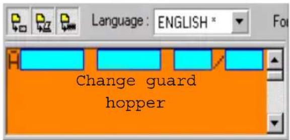
As the first line on this page has already been created and reserved for time-stamping alarms, enter the alarm text starting at line 2.
- Create another alarm page as explained in point 1.
2. Creation in XBT L100•
- Change the backlight color to red.
- Click on the Modify... button. Select the alarm activation bit (e.g., bit 4) and confirm by clicking on OK.
- Confirm by clicking on OK.
- Enter the following text:
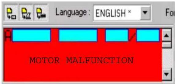
Step 6: Configuring the display unit
You wish page 2 to be displayed when the display unit is switched on:
- Click on the Terminal Parameters command from the Configuration menu.
- In the "Default page" zone, select page 2.
- Confirm by clicking on OK.
Step 7: Saving the application
Save the application using the Save command from the File menu (name: N401_2_m.dop (m for Modbus)).
Step 8: Application simulation
Verify the application using the Application Simulation command from the Simulation menu.
3. Loading the application into the display unit
The steps to load an application into a display unit are:
- Check that the display unit is powered off.
- Connect the PC to the terminal (see chapter A, section Connection, Page 11).
- Power up the display unit.
- Select the Export command from the Transfer menu to transfer the application to the display unit (see chapter C, section 6. Transferring an application, Page 63).
4. Using the application with the display unit
Reminder
A page consists of text and fields. A field can correspond to values, which need to be read (read mode), entered (write mode) or both (read/write mode), either by the operator, or by the PLC.

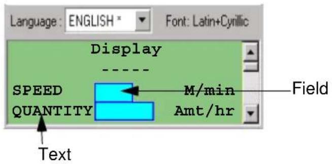
Input principle

In input mode, the MOD key is used for entry. All the digits in the selected field blink.
D
Input using the arrow keys

- Go to the digit to be input using the arrow keys. Once either key has been pressed, only the selected digit blinks.

- Increment/Decrement the value of the selected digit using the arrow keys.

- Go to the next digit using the arrow keys.

- Confirm the input globally with Enter.
Deleting characters

The DEL key deletes the digit or clears the selected field.
4. Using the application with the display unit
Print alarms as a data stream
Alarms are printed directly whenever they appear or change status.
The following information is printed:
- The alarm number
- The name of the alarm page
- The print date
- The print time
- The alarm status
Alarm log
The maintenance page can be used to access the function relating to the alarm log.
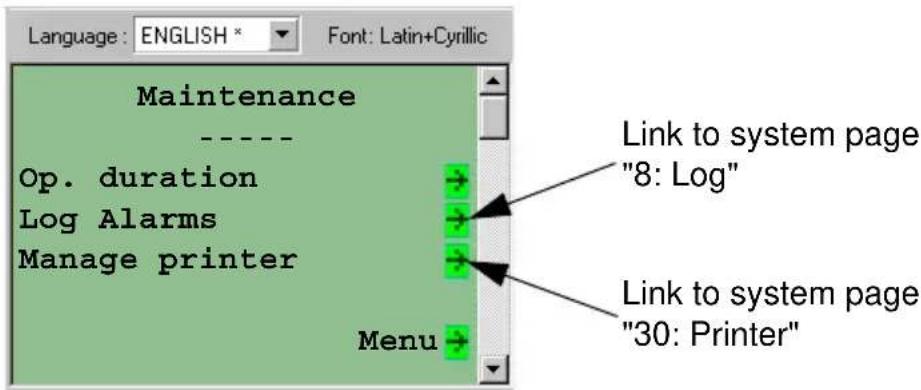
View log
To view the alarm log, simply go to system page "8: Log". The log can be viewed from a menu on this page.
Print log
To print the alarm log, simply go to system page "8: Log". The log can be printed from a menu on this page.
It is possible to stop the current print job. This function is available on system page "30: Printer".
Chapter E Appendices
Contents
Troubleshooting, error messages, terminology
- Troubleshooting/Problems and solutions 5
- Error messages ____ 7
- Internal variables 11
- Terminology 12
E
Contents
1. Troubleshooting/Problems and solutions
| Fault Cause Remedy | ||
| "Cannot read dialog table" message displayed on terminal | The equipment declared for the dialog table does not exist | Modify the list of equipment and check the declared addresses |
| No memory allocation for the dialog table has been declared in the PLC | Allocate memory space for the dialog table in the PLC (e.g., %MW100 to %MW125) | |
| The equipment is not connected to the terminal | Check the connection | |
| "Incorrect terminal type in .dop file" message displayed on terminal | The application has been exported to a terminal on which it was not designed to run | Modify the terminal type in the XBT L100• program and export the application again |
| "?????" displayed rather than any values | No memory allocation for this variable has been declared in the PLC | Allocate memory space for the variable |
| The equipment declared for the variable does not exist | Modify the list of equipment and check the declared addresses | |
| The equipment is not connected to the terminal | Check the connection | |
| The field is an enumerated list containing Chinese characters | Check that the field is not an enumerated list, which has been copied from an application in Chinese | |
| The terminal type selected in the application is not compatible with the terminal on which it is running. | Modify the terminal type in the XBT L100• program and export the application again | |
| The equipment is connected to the terminal via an XBT Z978 cable | Check the connection. Try using an XBT Z9780 cable | |
| The equipment is connected to the terminal via an XBT Z9780 cable | Check the connection. Try using an XBT Z978 cable (equivalent to an XBT Z9780 cable equipped with an XBT ZN999 adaptor). | |
| The XBT L100• program is not the latest version | Install the latest version of the XBT L100• program | |
| "Incorrect dialog table authorization" message | The value of the authorization word stored in the PLC is not correct | Using XBT L100•, check the expected value (...Configuration\Dialog Table) and its location in the equipment |
| Product "dead" XBT N401/NU | 400: No 24 V power supply | Check the power supply |
| XBT N200/400: No power supply via the PC mouse port. "Dialog table" forces the backlight to remain off. No power supply via the PLC communication port in run mode. | Check whether the PC mouse port has been activated (see PC Control Panel), check the PLC program. Check whether the cable is connected to the PLC port. Check that power is being supplied to the PLC. | |
| "Cannot read/write variable" message | The equipment declared for the variable does not exist | Check the addresses declared for the equipment |
| The variable does not have a valid address in the declared device | Check the variable address | |
| The equipment is not connected to the terminal | Check the connection | |
1. Troubleshooting/Problems and solutions
| Fault Cause Remedy | ||
| Import impossible XBT--> PC | Application protected by password Ask | the creator of the application for the password |
| Inoperative keys Locking by the | dialog table Check the PLC program | |
| Incorrect terminal configuration Check | that the terminal configuration is correct for "input" or "control" mode | |
| "No application" message No | application Transfer an application | |
| No printing No connection Con | nect the cable and check that it | is connected correctly at both ends. Then check that the printer is switched on. |
| The cable connecting the printer to the terminal is incorrect | Check that the cable is the appropriate type | |
| Incorrect printer configuration Refer to | the printer manual to check that the configuration saved by the terminal is the same as the current configuration | |
| Abnormal printing | Every other line is printed | The terminal is configured as LF rather than auto-LF |
| Lines are printing one on top of the other. | The terminal is configured as auto-LF rather than LF | |
2. Error messages
System messages generated by the XBT (single-language system messages: English), non-configurable.
APPLICATION FAULT: Application error (inconsistency).
AUTOTEST IN PROGRESS: Autotests running.
BIOS ERROR # x CS:x IP:x: Fatal BIOS error, consult Schneider Electric.
CHECKSUM FAILED: Firmware checking error.
DOWNLOAD ABORTED: Download to the XBT canceled by the operator.
DOWNLOAD COMPLETED: Download to the XBT finished.
DOWNLOAD FAILED: Download to the XBT failed.
DOWNLOAD IN PROGRESS: Download to the XBT in progress.
FPU ERROR # function x: Fatal math libraries error, consult Schneider Electric.
INCORRECT TERMINAL TYPE IN .DOP FILE: Export error, the application is exported to a terminal type X when it had been created for a terminal type Y.
KERNEL TRAP #x ES:x IP:x: Fatal real-time kernel error, consult Schneider Electric.
NO APPLICATION: Product has no application.
PROCESSOR TRAP # x CS:x IP:x: Fatal terminal error, consult Schneider Electric.
RUNTIME ERROR # x CS:x IP:x: Fatal RUNTIME error, consult Schneider Electric.
SWITCH POWER OFF CS:x IP:x: Fatal terminal error, consult Schneider Electric.
UPLOAD ABORTED: Upload to the PC canceled by the operator.
UPLOAD COMPLETED: Upload to the PC finished.
2. Error messages
UPLOAD FAILED: Download to the PC failed.
UPLOAD IN PROGRESS: Upload to the PC in progress.
WAITING FOR TRANSFER: Awaiting remote loading.
WIRING FAULT: Wiring problem.
2. Error messages
XBT system messages (6 languages), which can be translated by XBT L100• in the system pages.
ALARM LIST EMPTY: No alarms logged in the terminal.
CANNOT READ DIALOG TABLE: Connection problems between XBT <-> PLC.
CANNOT READ VARIABLE: Variable cannot be read.
CANNOT WRITE DIALOG TABLE: Writing to a protected zone or XBT <-> PLC connection problems.
CANNOT WRITE VARIABLE: Variable cannot be written.
CONNECTION IN PROGRESS: XBT is trying to connect to the PLC.
DATE FORMAT INVALID: The date cannot be displayed because of its format.
DIALOG TABLE AUTHORIZATION: Authorization word is incorrect.
LANGUAGE DOES NOT EXIST: Language not entered in the XBT.
LANGUAGE IMPOSED BY THE PLC: Current language determined by the PLC.
LOG CLEARING IN PROGRESS: Following an operator request, the log is being cleared.
OVERFLOW MIN <= VALUE <= MAX: Input of a value, which is outside the limits.
PAGE DOES NOT EXIST:Call-up of a non-existent page.
PASSWORD IMPOSED BY THE PLC: Current password determined by the PLC.
PRINTING STOPPED BY USER: The operator sent a request to stop the current print job: The next job in the print buffer will be printed as soon as the end of the line in the first print job is reached.
2. Error messages
PRINT RECOGNISED: The print request sent by the operator has been accepted and placed in the processing buffer: it will be processed as soon as the current print job is completed.
PROTECTED ACCESS PAGE: Call-up of a page protected by password.
REFUSED: PRINTING IS ALREADY IN PROGRESS: The same print request was sent twice in succession by the operator before the first print request could be fulfilled. The request is rejected.
TIME FORMAT INVALID: The time cannot be displayed because of its format.
WRONG PASSWORD: Input of an incorrect password.
3. Internal variables
| Variable Type Description | |
| %MW50000 String Date in ASCII | |
| %MW50001 String Time in ASCII | |
| %MW50002 Word Seconds (0 to 59) | |
| %MW50003 Word Minutes (0 to 59) | |
| %MW50010 to %MW50056 | Word Free word |
| %MW50057 Word Quick increment from 0 to 65535 | |
| %MW50058 Word Quick decrement from 65535 to 0 | |
| %MW50059 Word Increment from 0 to 9 every 2 seconds | |
| %MW50060 Word Decrement from 9 to 0 every 2 seconds | |
| %MW10028 Word Value of the programmed language | |
| %MW10033 String Password level in progress | |
| %MW10034 String Password input in progress | |
| %MW10035 Word Reset current password value (=0 for Reset). | |
4. Terminology
| Term used Definition | |
| Alarm page Page of information, which can be displayed | at the request of the control system by acting on the Boolean variable associated with it. |
| Alarm table (AT) Part of the dialog table completed by | a control system. This word list associates a word bit with an alarm. The alarm table enables a device to signal alarms to the terminal, and to know in return when the operator has acknowledged each alarm. The alarm table for the pilot device is a subset of the dialog table. |
| Alphanumeric display units These are only capable | of displaying characters (with a font resolution usually 5x7 pixels). The characters are physically separated from one another. |
| Alphanumeric terminals These are equipped with alphanumeric display units or matrix display units used in character mode only. | |
| API French translation of PLC. | |
| Application language An application can be created in | several languages, and each of these languages is an application language. |
| Application page Defined by the developer, this can be displayed by the operator or by the control system. It contains static text and possibly static graphics, variable fields and links. | |
| ATAcronym for Alarm Table (see the entry for this | word) |
| Bitmap Image with fixed dimensions, which can be handled by a Windows application. | |
| Button | Windows object used to perform the action described by its name (or symbol). A button is enabled by clicking the mouse or pressing Enter when it is selected. |
| Combo box | Windows object consisting of an edit field and a list box |
| Command table | Part of the dialog table completed by the control system. This word list contains all the instructions passed to the terminal. |
| Configuration software | Tool used to develop an operator dialog application and also transfer it to a target terminal. |
| Control system | Designates all the components of an automated installation: The control system (usually a PLC) controls the sensors, the actuators and the HMI terminal. |
| Current language | Language selected in the document bar; this is the language in which the developer is currently making modifications. |
| Daughter Page Application page, which can be called | by a Mother Page. |
4. Terminology
| Default language Application language used when the XBT is powered up. | |
| Dialog application Set of data, necessary and sufficient to describe the behavior of a terminal during operation. XBT L100• is the only tool, which can be used to create this type of application for Schneider Electric terminals. | |
| Dialog box (DB) Particular type of window containing controls, which enable data to be exchanged with the developer. | |
| Dialog table (DT) Word list containing the necessary information for a control system to access the terminal's human-machine-dialog functions. It consists of 3 parts called command table, alarm table and status table. | |
| Document Set of data forming a dialog application in the XBT L100• program. This term is used for compatibility with the architecture recommended by Microsoft ©. | |
| DT Acronym for Dialog Table (see the entry for this word) | |
| Edit field Windows object used to enter a character string from the keypad. | |
| Equipment Any device (usually a PLC) communicating with the terminal. | |
| Firmware This is the terminal on-board software. It comprises mainly the BIOS and the loader used to communicate with XBT L100•. | |
| Folio Page A Daughter Page but not a Mother Page. A page alias can be both Folio and Mother. | |
| Installer (Or tuning engineer) This is one of the users of the terminal in a control system. | |
| Link | Object contained in a page used to access application pages or system pages (navigation links) or to perform command functions (command links). |
| List box | Windows object usually containing a scroll bar, used to select an item from a list. |
| Loader | Part of terminal firmware responsible for handling communication with XBT L100• to transfer a dialog application in one direction or the other. Its role is also to store application data, sent by XBT L100•, in the terminal memory. |
| Loading | Action of reading a mass memory into the PC memory in order to use the data it contains. |
| Magelis | Generic trade name for all Schneider Electric operator terminals. |
| Matrix display units | These consist of a "continuous" matrix of pixels, enabling the display of characters in different fonts and sizes, and also basic graphics. The technology and resolution of these display units is however too low for them to be considered true "graphic" display units. |
| Menu | Heading located in the menu bar, selected in order to access a list of menu entries. |
4. Terminology
| Menu bar Zone located at the top of a Windows window | containing several headings corresponding to menus. |
| Menu entry Heading indicating a software function and | selected to enable access to it. Also known as "Command". |
Modal dialog box | While a modal dialog box is open, the developer cannot perform any other operations in the XBT L100• program. |
Modeless dialog box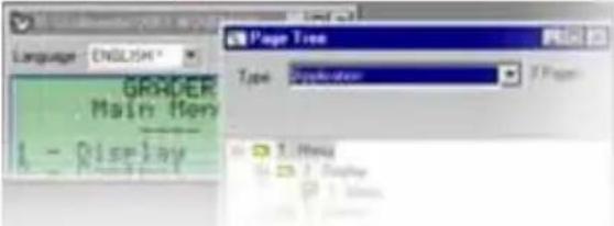 | The presence of a modeless dialog box does not prevent any operations in the XBT L100• program. |
| Mother Page Application page, which has at least one | Daughter Page. |
| Node page Application page, which has a Mother Page | and at least one Daughter Page. |
| Operator Person who uses a terminal in run mode within a control system. | |
| Page Can be displayed on the terminal. It may be larger | than the display unit. Scrolling is used to move the visible screen area. Pages can be different types, as listed below. |
| Page editor Part of a document window used to edit the content of any type of page. | |
| Pilot device A terminal can communicate with several | control system-devices. Of these, only one is able to send commands to the terminal, and is capable of knowing its status; this device is called the pilot device. It contains the dialog table. |
| PLC Programmable Logic Controller | |
| Protocol Enables communication between the terminal | and the connected equipment in several types of architecture. |
| Radio button Windows object usually used in a group | and supporting the selection of a single option. |
| Reference language Language in which the manufacturer constructs his application pages. By default, it is the installation language of the XBT L100• program. | |
| Root Page | A page, which can be a Mother Page but not a Daughter Page. |
4. Terminology
| Run mode Operating mode in which the terminal is | communicating with one or more connected devices and is running an application. |
| Screen Designates a terminal display unit. As a page can sometimes be bigger than the display unit, by extension the term screen also designates a subset of the page, this subset being the same size as the display unit. | |
| Service keys Keys on the keypad necessary for certain terminal functions (scrolling, selecting fields, data input, requesting a menu, etc.). | |
| Shortcut menu Quick method of displaying commands linked to a specific work situation. | |
| Static function keys (SFK) Keys used to access pages or perform command operations; their action stays the same regardless of the dialog-application context. | |
| Status bar Zone located at the bottom of a Windows window, used to indicate the state of the application or active element to the developer. | |
| Status table Part of the dialog table completed by the terminal. This word list represents the terminal status. | |
| Terminal Component consisting of on-board software | capable of functions designed for inclusion in a dialog application to ensure a human-machine interface is suitable for the process into which it is integrated. |
| Thumbwheel input Rudimentary input mode based on the same principle as mechanical thumbwheels: selection of the digit to be modified by means of the horizontal arrow key(s), then selection of the digit value by means of the vertical arrow key(s). | |
| Toolbar Zone of a Windows window usually located | underneath the menu bar and containing buttons, which can be activated by the mouse. The function associated with each button can also be accessed from the keypad (usually by a menu entry). |
| Transfer mode Operating mode in which the target terminal and the PC running XBT L100• can communicate to transfer a dialog application in one direction or the other. | |
| Tree structure Structure representing the application pages and the links between them. By extension, this window is used to represent the structure of all types of page. | |
| User | Operator who uses a terminal in run mode on site. This is the generic term used to designate any of the 3 profiles defined above: Developer, Installer, Operator. |
| Variable field | Area on a terminal display unit configured to display an item depending on the value of an object in the connected control system. |
| Windows application | Program, which runs in the Windows environment. |
| WYSIWYG | (What You See Is What You Get) Representation of a physical element on the PC screen, which simulates its true appearance. |
4. Terminology
INDEX
A
Alarm bit C - 30
Alarm list B - 19, B - 20, B - 21
Alarm log B - 21, B - 41
Clearing B - 42
Display B - 42
Principles B - 41
Alarm pages A - 20, B - 40, C - 29, E - 12
Acknowledgment B - 21, B - 40
Acknowledgments C - 31
Advantages in run mode B - 19
Appearance types B - 20
Creation C - 29
Display B - 22, B - 40
Display priority B - 19
Ignoring alarms B - 40
Log B - 21, B - 41
Objective B - 18
Principle B - 18
Principles B - 18
Properties C - 31
Storage principle B - 20
Viewing B - 40
Alarm table E - 12
Alarms
Objective B - 18
Alias C - 32
Alphanumeric display units E - 12
Alphanumeric terminals E - 12
Alphanumeric variable fields C - 43
Access to fields C - 44
Condition C - 48
Conversion C - 46
Display C - 46
Display format C - 43
Enumerated lists C - 47
Length C - 43
Limits C - 45
Number of digits C - 44
Properties C - 43
Size C - 43
Appearance types B - 20
Application C - 5
Application example D - 5
Application pages D - 10
Configuring the display unit D - 21
Creation D - 10
Dialog table D - 9, D - 19
Equipment D - 10
Loading into the display unit D - 22
Page structure D - 9
Saving D - 21
Simulation D - 21
Application pages A - 20, C - 27, E - 12
Creation C - 27
Definition B - 17
Display B - 31
Principle B - 17
Properties C - 28
Protection C - 28
AT E - 12
B
Bar
Menu C - 6, E - 14
Status E - 15
Tool E - 15
Bitmap E - 12
Button E - 12
C
Cable A - 15, B - 11
Character font C - 33, C - 35
Chinese C - 36
Cyrillic C - 35, C - 36
Greek C - 36
Katakana C - 35
Characteristics A - 15
Childless page E - 13
Chinese C - 36
Chinese characters C - 38
Circular text C - 41
Combo box E - 12
Command data C - 55
Command table E - 12
Common data sent/received C - 56
Configuration of equipment C - 20
Configuration of protocol
parameters C - 19
Configuration of terminal
parameters C - 15
Confirming an input B - 37
Connection A - 11, C - 63
Multidrop B - 16
Multipoint B - 16
Control system E - 12
Control-system architectures B - 15
Multidrop connection B - 16
Multipoint connection B - 16
Point-to-point connection B - 15
Copy/paste C - 11
Creating a new application C - 13
With wizard C - 24
Without wizard C - 13
D
Date and time B - 47
Display format B - 47
Input B - 47
Daughter Page E - 12
Description
Front panel A - 7
Rear panel A - 8
Description of the display units A - 7
Dialog application E - 13
Dialog between the PLC and the
display unit B - 8
Dialog Box E - 13
Dialog table C - 26, C - 53, E - 13
Concepts C - 53
Configuration C - 24, C - 56
Description C - 65
Display of a page B - 32
Display of an application page
From system pages B - 33
On power-up B - 31
Via a navigation link B - 32
Via function keys B - 31
Via the PLC B - 32
Display unit parameters C - 26
Display unit self-tests B - 23
Continuous B - 23
On power-up B - 23
Document E - 13
DT E - 13
E
Edit field E - 13
Entering the application name C - 24
Enumerated lists C - 47
Equipment E - 13
Equipment symbols C - 20
Configuration C - 25
Configuration of equipment C - 20
Import C - 21
Principle C - 20
Exchanged data C - 54
F
Firmware E - 13
Function keys
Configuration C - 49
Creating labels C - 50
Functional command link B - 29
Representation B - 30
Functional links C - 51
Configuration C - 52
Creation C - 51
H
Human/machine dialog B - 5
|
Importing an application C - 15, C - 63
Impulse command B - 27
Indicator light
Communication B - 11
Indicator-light functions B - 26
Input
Cancellation B - 37
Deleting characters D - 23
Exit on time out B - 38
Of a value B - 36
Principle D - 23
Report B - 38
Using the arrow keys D - 23
Input/Modification of a value B - 35
Installer E - 13
K
Key functions B - 24
L
Language B - 46, C - 22, C - 25, E - 12
Translation C - 39
Line parameters B - 49
Error counters B - 49
Link E - 13
List-box E - 13
Loader E - 13
Loading E - 13
M
Magelis E - 13
Magelis application C - 5
Matrix display units E - 13
Menu E - 13
Menu entry E - 14
Modal dialog box E - 14
Modeless dialog box E - 14
Modifiable characters C - 37
Mother Page E - 14
N
Navigation links C - 33
Node Page E - 14
O
Operating modes B - 9
Run mode B - 9, B - 12, B - 17, E - 15
Transfer mode B - 9, B - 10, E - 15
Operator E - 14
Organization of Magelis functions B - 14
P
Page E - 14
Page editor E - 14
Pilot equipment E - 14
PLC E - 12, E - 14
Presentation of the software C - 6
Printing B - 43
Alarm log B - 43
As a data stream B - 43
Configuration C - 16
Lists of current alarms B - 44
Principles B - 43
Process commands
Via function keys B - 28
Via functional links B - 29
Product references B - 48
Protecting the application C - 19
Protecting the display unit B - 13
Protocols B - 15, E - 14
R
Radio button E - 14
Range A - 5
Root Page E - 14
S
Screen E - 15
Scrolling within a page B - 33, B - 34
Select the type of terminal C - 13
Selection of an input field B - 35
By the operator B - 35
By the pilot equipment B - 36
Service keys E - 15
Setting the display unit
parameters B - 46
Shortcut menu E - 15
Simulation A - 20, C - 58
Display-unit simulation window C - 58
PLC simulation window C - 59
Software A - 20, E - 12
Field information window C - 9
Functions A - 20
Installation A - 19
Navigation window C - 9
Opening C - 6
Presentation A - 19, C - 6
Special characters C - 37
Starting up the display unit C - 63
Static function keys E - 15
Status data C - 55
Status table E - 15
Structure of Magelis applications
B - 5
System pages B - 17, B - 39, C - 31
Definition B - 17
Display from an application page B - 39
Display from the dialog table B - 39
Principle B - 17
Properties C - 31
T
Terminal E - 15
Text C - 33
Alignment C - 12
Character size C - 33
Import/export text C - 39
Inserting Chinese characters C - 38
Inserting special characters C - 37
Modifiable characters C - 37
Properties C - 33
Thumbwheel input E - 15
Toggle command B - 27
Toolbar C - 7
Tree structure E - 15
Type of page C - 10
U
User E - 15
V
Variable field E - 15
W
Windows application E - 15
Word
Alarm table C - 84
Application checksum C - 72
Clear log/Advanced functions C - 78
Communication monitoring C - 68
Images of static/system/numeric function keys C - 67
Light up static function key LEDs C - 81
Locking static/system/numeric function keys C - 82
Log fill level C - 72
Number of field to be completed C - 75
Number of last acknowledged alarm C - 71
Number of last completed field C - 70
Number of page displayed C - 70
Number of page to be processed C - 70, C - 74
Print command C - 77
Report B - 38, C - 71
Set PLC clock C - 69
Set terminal clock C - 85
Terminal language C - 83
Write table authorization C - 78
WYSIWYG E - 15
The appearance, operation and use of the products, hardware and equipment described in this document may be changed or modified at any time. Their description can under no circumstances be deemed to be contractual in nature.
© Copyright Telemecanique 2006. This document may not be reproduced. It is forbidden to reproduce or copy any part of this document using photographic, electronic or any other means, or to transcribe it in whole or part to a format which could be read by an electronic machine.
- DANGER
- WARNING
- CAUTION
- PLEASE NOTE
- Conventions
- Chapter A Introduction
- Contents
- XBT N/XBT R display units
- Presentation of the range
- Description
- On the front panel
- On the rear panel
- Presentation of the commands
- - XBT N:
- - XBT R:
- XBT N display-unit commands
- Static function keys:
- 2a Control mode:
- 2b Input mode:
- Service keys
- - Clear the selected digit or field
- - Go up, go down in a page (XBT N40• and NU400)
- - Select a field
- - Confirm a selection or an entry
- Dual-label keys (function/numeric):
- Link or contextual control keys:
- - Go up, down within a page
- Connection
- Magelis-PC link: Application transfer
- Power supply mode: Powered by the PLC
- Power supply mode: 24 V DC external power supply
- Magelis-PLC link: Running
- Characteristics
- The XBT L100• program
- Presentation
- Installation
- Functions
- Chapter B
- Using the
- XBT N/XBT R display units
- Introduction: Display unit operating concepts
- HMI
- Production monitoring
- ■ Preventive maintenance
- ■ Corrective maintenance
- ■ Process control
- Dialog between the PLC and the display unit
- LOSS OF CONTROL
- Operating modes
- Transfer mode
- Cable connection
- Procedure with XBT L100•
- Communication indicator light
- Run mode
- Protection
- UNAUTHORIZED ACCESS
- Organization of Magelis functions
- Control-system architectures
- Protocols
- Point-to-point connection
- ■ Multipoint connection (XBT N401/N410/NU400/R410/R411)
- ■ Multidrop connection (XBT N401/N410/R410/R411)
- ■ Principle of application pages
- Definition
- ■ Principle of system pages
- Principle of alarm pages
- Objective
- Advantages in run mode
- ALARM
- ■ Display priority
- Exception for priority 0
- Appearance types
- ■ Storage principle in the alarm list
- Acknowledgment of alarms
- - Alarms, which must be acknowledged (obligatory)
- – Alarms, which can be acknowledged but do not have to be
- Alarm log
- ■ Display unit self-tests
- ■ Self-test on power-up
- Continuous self-test
- Keys and indicator lights
- Key functions
- Exception for XBT R display units:
- Indicator-light functions (XBT N401/R411)
- Sending commands to the control system
- Types of command
- Impulse command
- Toggle command
- Commands sent via function keys
- Commands sent via functional links
- Functional command link
- ■ Representation of command links
- Application pages
- ■ Display of an application page
- On power-up (default page)
- Via function keys
- IMPROPER OPERATION
- Via a navigation link
- Via the PLC
- From system pages
- Scrolling within a page
- Alphanumeric fields
- Input/Modification of a value
- Selection of an input field
- By the operator
- By the pilot device
- ■ Entering a value (1)
- Confirming an input
- ENTER key
- Canceling an input
- ESC key
- Exit input on time out
- Input report
- ■ Display from an application page
- ■ Display from the dialog table
- Alarm pages
- Alarm displays
- ■ Possibility of ignoring alarms
- Viewing alarms
- Log principles
- View the log
- Clear the log
- Principles
- Print alarms as a data stream
- Print the alarm log
- ■ Initiated by the operator
- ■ Initiated by the PLC
- Print the list of current alarms
- Printing
- Stop printing
- Setting the display unit parameters
- Application language
- Date and time
- ■ Entering the date and time
- ■ Selecting the display format
- Product references
- Line parameters
- Chapter C
- Detailed description of the XBT L100• program
- Software functions for creating an application:
- Introduction: Creating Magelis applications
- Presentation of the XBT L100• program
- Launching the program in Windows
- Presentation of the software
- Menu bar
- Toolbar
- Editor toolbar
- Field information window
- Navigation window
- General
- Using copy/paste
- Alignment
- Using XBT L100• software
- Creating a new application
- Creation without a wizard
- Step 1 - Select the type of terminal
- Step 2 - Configure the terminal parameters
- Application-import configuration
- Configure printer
- Step 3 - Configure the protocol parameters
- Step 4 - Configure the equipment
- Principle
- Configuration equipment window
- Importing PLC symbols
- Step 5 - Select the application languages
- NOTE: If the font selected initially was Chinese and the user chooses to stop using this language, Chinese characters already entered in the application will be replaced with “?”.
- Step 6 - Configure the dialog table
- ■ Creation with a wizard
- Step 1 - Enter the application name
- Step 2 - Configure the equipment
- Step 3 - Configure the application languages
- Application pages
- Creating a page
- Page properties
- Protecting a page
- NOTE: When creating an application page, the protection values offered by default are those selected for protection of a previous page.
- Alarm pages
- Creation
- Page appearance types
- - Alarm acknowledgments
- System pages
- Alias
- Navigation links
- Text
- Properties
- Character fonts
- Modifiable characters
- Inserting special characters
- Inserting Chinese characters
- Importing/Exporting text for translation
- Circular text
- Length:
- Size:
- Circular text:
- Alphanumeric variable fields
- Field properties
- Display format
- Operator access to fields:
- Protection:
- Limits:
- Constant limits:
- Variable limits:
- NOTE: These variables are only read when the request is made to display the page containing the variable object concerned.
- Conversion
- Display:
- Enumerated lists
- Condition
- Configuring the function keys
- Creating labels
- NOTE: As each printer is configured with different margins, it is advisable to test print on a sheet of paper before using a sheet of labels.
- Functional links
- Creating links
- Configuration
- Introduction: Concepts
- Dialog table
- Exchanged data
- Command data sent by the PLC to the display unit
- ■ Status data sent by the display unit to the PLC
- ■ Common data sent/received
- Configuring the dialog table
- Introduction
- ■ Display-unit simulation window
- Simulation
- ■ Keypad keys during simulation
- PLC simulation window
- ■ "Page Variables" tab
- "Alarms" tab
- "Dialog Table" tab
- ■ "Printer Output" tab
- Transferring an application
- Connecting the display unit
- ELECTRICAL CONNECTIONS
- Starting up the display unit
- - Importing an application
- - Exporting an application
- Description of dialog-table words
- Detailed description
- Images of static/system/numeric function keys
- ■ Communication monitoring
- Set PLC clock
- ■ Number of page displayed
- ■ Number of last completed field
- ■ Number of last acknowledged alarm (1)
- Log fill level
- Application checksum
- ■ Terminal advanced state
- Current password level:
- ■ Number of page to be processed
- ■ Number of field to be completed
- Print command
- Write table authorization
- Clear log/Advanced functions
- Function 0:
- Function 1:
- Function 2:
- ■ Static function keys on
- ■ Locking static/system/numeric function keys
- Terminal language
- Alarm table (1)
- Set terminal clock
- Chapter D
- Example of a simple application
- Application content
- Page structure
- Step 1: Creating the application
- Step 2: Creating the equipment
- Step 3: Creating application pages
- Creation in XBT L100•
- Step 4: Configuring the dialog table
- Step 5: Creating alarm pages
- Step 6: Configuring the display unit
- Step 7: Saving the application
- Step 8: Application simulation
- Loading the application into the display unit
- Using the application with the display unit
- Reminder
- Input principle
- Input using the arrow keys
- Deleting characters
- View log
- Print log
- Chapter E Appendices
- Troubleshooting, error messages, terminology
- Troubleshooting/Problems and solutions
- Error messages
- Internal variables
- Terminology
- INDEX
- A
- B
- C
- D
- E
- F
- H
- |
- K
- L
- M
- N
- O
- P
- R
- S
- T
- U
- V
- W
- Word
Brand : SCHNEIDER
Model : XBTN401
Category : Commande