
SR3XT141BD - Uncategorized SCHNEIDER - Free user manual and instructions
Find the device manual for free SR3XT141BD SCHNEIDER in PDF.


| Product Type | Smart Relay Input/Output Extension Module |
| Model | Schneider SR3XT141BD |
| Inputs | 8 discrete inputs (24 VDC), including 4 analog inputs (0-10 VDC) also usable as discrete |
| Outputs | 6 relay outputs (8 A each) |
| Power Supply | 24 VDC regulated, 19.2 to 30 VDC |
| Dimensions (approx.) | 90 x 70 x 60 mm (3.5 x 2.8 x 2.4 in) |
| Weight (approx.) | 200 g (7.1 oz) |
| Operating Temperature | -20 to 55 °C (-4 to 131 °F) |
| Protection Class | IP20 (enclosure required) |
| Compatible Smart Relays | Zelio Logic SR2, SR3 series (with LCD/keypad or without) |
| Main Functions | Expands I/O count of smart relay; supports up to 240 ladder lines (without SR2COM01); 28 auxiliary relays, 28 counters, 28 timers, 8 clocks, analog comparison, fast counter, communication via Modbus (via SR2COM01) |
| Programming | Ladder (LD) or Function Block (FBD) via front panel or Zelio Soft 2 software |
| Backup Memory | Supports SR2MEM01 (program only) and SR2MEM02 (program + firmware) cartridges |
| Maintenance | No user-serviceable parts; battery non-replaceable; clean with dry cloth; avoid moisture |
| Safety Features | Watchdog timer, password protection, input filtering (fast/slow), error detection and logging |
| Spare Parts & Repairability | Integrated design; no field-replaceable components; contact Schneider Electric for repair |
| General Information | Designed for industrial automation; must be installed in a suitable enclosure; comply with local safety regulations |
Frequently Asked Questions - SR3XT141BD SCHNEIDER
User questions about SR3XT141BD SCHNEIDER
0 question about this device. Answer the ones you know or ask your own.
Ask a new question about this device
Download the instructions for your Uncategorized in PDF format for free! Find your manual SR3XT141BD - SCHNEIDER and take your electronic device back in hand. On this page are published all the documents necessary for the use of your device. SR3XT141BD by SCHNEIDER.
USER MANUAL SR3XT141BD SCHNEIDER
The information provided in this documentation contains general descriptions and/or technical characteristics of the performance of the products contained herein. This documentation is not intended as a substitute for and is not to be used for determining suitability or reliability of these products for specific user applications. It is the duty of any such user or integrator to perform the appropriate and complete risk analysis, evaluation and testing of the products with respect to the relevant specific application or use thereof. Neither Schneider Electric nor any of its affiliates or subsidiaries shall be responsible or liable for misuse of the information contained herein. If you have any suggestions for improvements or amendments or have found errors in this publication, please notify us.
You agree not to reproduce, other than for your own personal, noncommercial use, all or part of this document on any medium whatsoever without permission of Schneider Electric, given in writing. You also agree not to establish any hypertext links to this document or its content.
Schneider Electric does not grant any right or license for the personal and noncommercial use of the document or its content, except for a non-exclusive license to consult it on an "as is" basis, at your own risk. All other rights are reserved.
All pertinent state, regional, and local safety regulations must be observed when installing and using this product. For reasons of safety and to help ensure compliance with documented system data, only the manufacturer should perform repairs to components.
When devices are used for applications with technical safety requirements, the relevant instructions must be followed.
Failure to use Schneider Electric software or approved software with our hardware products may result in injury, harm, or improper operating results.
Failure to observe this information can result in injury or equipment damage.
© 2017 Schneider Electric. All Rights Reserved.
Table of Contents

Safety Information....7
About the Book.... 11
Part I Initial Power up and Discovering 19
Chapter 1 Initial Power up and Discovering 21
Presentation of the Smart Relay Front Panel 22
Characteristics and Connections.... 24
Control Keys on the Front Panel of the Smart Relay. 25
Examples.... 27
Part II Functions Accessible from the Front Panel ..... 33
Chapter 2 Overview of the Functions Accessible from the Front
Panel.... 35
Functions Accessible from the Front Panel of the Smart Relay ..... 35
Chapter 3 Input/Output Screen 37
Inputs-Outputs Screen. 38
TEXT and DISPLAY screen 40
Chapter 4 PROGRAMMING Menu 43
Rules for Entering Ladder Diagrams 45
Method for Entering a Contact or Coil 47
Entering a Link. 50
Entry of Function Block Parameters 52
Deletion and Insertion of Diagram Lines 53
Chapter 5 PARAMETERS Menu.... 55
PARAMETERS Menu 55
Chapter 6 MONITORING Menu 57
MONITORING Menu 57
Chapter 7 RUN/STOP Menu....59
RUN/STOP Menu 59
Chapter 8 CONFIGURATION Menu 61
PASSWORD Menu 62
FILTER Menu 65
Zx KEYS Menu 66
WATCHDOG CYCLE Menu 67
Chapter 9 CLEAR PROGRAM Menu 69
CLEAR PROG Menu. 69
Chapter 10 TRANSFER Menu 71
TRANSFER Menu 71
Chapter 11 VERSION Menu 75
VERSION Menu. 75
Chapter 12 LANGUAGE Menu 77
LANGUAGE Menu 77
Chapter 13 DEFAULT Menu....79
DEFAULT Menu. 79
Chapter 14 CHANGE DATE/TIME Menu 83
CHANGE DATE/TIME Menu 83
Chapter 15 CHANGE SUMMER/WINTER Menu 85
CHANGE SUMMER/WINTER Menu 85
Part III LD Language 87
Chapter 16 LD Language Elements 89
Introduction 90
Discrete Inputs 91
Zx Keys 93
Auxiliary Relays 95
Discrete Outputs 98
Timers 101
Counters.... 110
Fast Counter 116
Counter Comparators.... 125
Analog Comparators 127
Clocks 132
TEXT 135
LCD Screen Backlighting 137
Change to Summer / Winter Time 138
Modbus Inputs/Outputs 140
Message.... 141
Part IV Creating and Debugging an Application. 143
Chapter 17 Implementing an Application 145
Presentation of Ladder Diagrams 146
Using the Reverse Function.... 148
Notation Used by the Smart Relay. 150
Application: Implementing a Two-way Switch 152
Chapter 18 Debugging an Application.... 159
Introduction 160
Run Mode Ladder Diagrams 162
Run Mode Function Block Parameters 163
Run Mode Menus 164
Smart Relay Reaction to a Power Outage. 165
Chapter 19 Transfer of Ladder Diagrams ..... 167
Transferring Ladder Diagrams. 167
Chapter 20 Sample Application.... 169
Specifications 170
Specification Analysis 171
Implementing the Solution 173
Part V Diagnostics 177
Chapter 21 Diagnostics.... 179
Smart Relay Messages 180
Frequently Asked Questions 181
Appendices 183
Appendix A Compatibility 185
Zelio Soft 2 Software Version Versus Functions 186
Compatibility between the memory cartridges and the version of the
firmware on the smart relay 187
Index 189
Important Information
NOTICE
Read these instructions carefully, and look at the equipment to become familiar with the device before trying to install, operate, service, or maintain it. The following special messages may appear throughout this documentation or on the equipment to warn of potential hazards or to call attention to information that clarifies or simplifies a procedure.

The addition of this symbol to a "Danger" or "Warning" safety label indicates that an electrical hazard exists which will result in personal injury if the instructions are not followed.

This is the safety alert symbol. It is used to alert you to potential personal injury hazards. Obey all safety messages that follow this symbol to avoid possible injury or death.
DANGER
DANGER indicates a hazardous situation which, if not avoided, will result in death or serious injury.
WARNING
WARNING indicates a hazardous situation which, if not avoided, could result in death or serious injury.
CAUTION
CAUTION indicates a hazardous situation which, if not avoided, could result in minor or moderate injury.
NOTICE
NOTICE is used to address practices not related to physical injury.
PLEASE NOTE
Electrical equipment should be installed, operated, serviced, and maintained only by qualified personnel. No responsibility is assumed by Schneider Electric for any consequences arising out of the use of this material.
A qualified person is one who has skills and knowledge related to the construction and operation of electrical equipment and its installation, and has received safety training to recognize and avoid the hazards involved.
BEFORE YOU BEGIN
Do not use this product on machinery lacking effective point-of-operation guarding. Lack of effective point-of-operation guarding on a machine can result in serious injury to the operator of that machine.
WARNING
UNGUARDED EQUIPMENT
- Do not use this software and related automation equipment on equipment which does not have point-of-operation protection.
- Do not reach into machinery during operation.
Failure to follow these instructions can result in death, serious injury, or equipment damage.
This automation equipment and related software is used to control a variety of industrial processes. The type or model of automation equipment suitable for each application will vary depending on factors such as the control function required, degree of protection required, production methods, unusual conditions, government regulations, etc. In some applications, more than one processor may be required, as when backup redundancy is needed.
Only you, the user, machine builder or system integrator can be aware of all the conditions and factors present during setup, operation, and maintenance of the machine and, therefore, can determine the automation equipment and the related safeties and interlocks which can be properly used. When selecting automation and control equipment and related software for a particular application, you should refer to the applicable local and national standards and regulations. The National Safety Council's Accident Prevention Manual (nationally recognized in the United States of America) also provides much useful information.
In some applications, such as packaging machinery, additional operator protection such as point-of-operation guarding must be provided. This is necessary if the operator's hands and other parts of the body are free to enter the pinch points or other hazardous areas and serious injury can occur. Software products alone cannot protect an operator from injury. For this reason the software cannot be substituted for or take the place of point-of-operation protection.
Ensure that appropriate safeties and mechanical/electrical interlocks related to point-of-operation protection have been installed and are operational before placing the equipment into service. All interlocks and safeties related to point-of-operation protection must be coordinated with the related automation equipment and software programming.
NOTE: Coordination of safeties and mechanical/electrical interlocks for point-of-operation protection is outside the scope of the Function Block Library, System User Guide, or other implementation referenced in this documentation.
START-UP AND TEST
Before using electrical control and automation equipment for regular operation after installation, the system should be given a start-up test by qualified personnel to verify correct operation of the equipment. It is important that arrangements for such a check be made and that enough time is allowed to perform complete and satisfactory testing.
WARNING
- Verify that all installation and set up procedures have been completed.
- Before operational tests are performed, remove all blocks or other temporary holding means used for shipment from all component devices.
- Remove tools, meters, and debris from equipment.
Failure to follow these instructions can result in death, serious injury, or equipment damage.
Follow all start-up tests recommended in the equipment documentation. Store all equipment documentation for future references.
Software testing must be done in both simulated and real environments.
Verify that the completed system is free from all short circuits and temporary grounds that are not installed according to local regulations (according to the National Electrical Code in the U.S.A, for instance). If high-potential voltage testing is necessary, follow recommendations in equipment documentation to prevent accidental equipment damage.
Before energizing equipment:
- Remove tools, meters, and debris from equipment.
- Close the equipment enclosure door.
- Remove all temporary grounds from incoming power lines.
- Perform all start-up tests recommended by the manufacturer.
OPERATION AND ADJUSTMENTS
The following precautions are from the NEMA Standards Publication ICS 7.1-1995 (English version prevails):
- Regardless of the care exercised in the design and manufacture of equipment or in the selection and ratings of components, there are hazards that can be encountered if such equipment is improperly operated.
- It is sometimes possible to misadjust the equipment and thus produce unsatisfactory or unsafe operation. Always use the manufacturer's instructions as a guide for functional adjustments. Personnel who have access to these adjustments should be familiar with the equipment manufacturer's instructions and the machinery used with the electrical equipment.
- Only those operational adjustments actually required by the operator should be accessible to the operator. Access to other controls should be restricted to prevent unauthorized changes in operating characteristics.
At a Glance
Document Scope
This manual describes the use of functions accessible from the front panel of the smart relay.
This document is divided into 5 parts and addresses the following topics:
• Part I: Powering up and Discovering the Smart Relay
- General presentation of the smart relay
- Part II: Functions Accessible from the Front Panel
○ Description of the interface and the menus of the smart relay
• Part III: LD Language
○ Description of automation functions available for programming in LADDER
- Part IV: Creating, Debugging and Saving an Application
Example of programming
o Presentation of tools for debugging and saving an application
• Part V: Diagnostics
- Help for finding solutions to detected errors
Validity Note
This document has been updated for the release of Zelio Soft 2 V5.1.
The technical characteristics of the devices described in this document also appear online. To access this information online:
| Step Action | |
| 1 Go to the Schneider Electric home page www.schneider-electric.com. | |
| 2 | In the Search box type the reference of a product or the name of a product range.Do not include blank spaces in the reference or product range.To get information on grouping similar modules, use asterisks (*). |
| 3 | If you entered a reference, go to the Product Datasheets search results and click on the reference that interests you.If you entered the name of a product range, go to the Product Ranges search results and click on the product range that interests you. |
| 4 | If more than one reference appears in the Products search results, click on the reference that interests you. |
| 5 | Depending on the size of your screen, you may need to scroll down to see the data sheet. |
| 6 | To save or print a data sheet as a .pdf file, click Download XXX product datasheet. |
The characteristics that are presented in this manual should be the same as those characteristics that appear online. In line with our policy of constant improvement, we may revise content over time to improve clarity and accuracy. If you see a difference between the manual and online information, use the online information as your reference.
For product compliance and environmental information (RoHS, REACH, PEP, EOLI, etc.), go to www.schneider-electric.com/green-premium.
Product Related Information
⚠️! DANGER
HAZARD OF ELECTRIC SHOCK, EXPLOSION OR ARC FLASH
- Disconnect all power from all equipment including connected devices prior to removing any covers or doors, or installing or removing any accessories, hardware, cables, or wires except under the specific conditions specified in the appropriate hardware guide for this equipment.
- Always use a properly rated voltage sensing device to confirm the power is off where and when indicated.
- Replace and secure all covers, accessories, hardware, cables, and wires and confirm that a proper ground connection exists before applying power to the unit.
- Use only the specified voltage when operating this equipment and any associated products.
Failure to follow these instructions will result in death or serious injury.
! DANGER
POTENTIAL FOR EXPLOSION
- Only use this equipment in non-hazardous locations, or in locations that comply with Class I, Division 2, Groups A, B, C and D.
- Do not substitute components which would impair compliance to Class I, Division 2.
- Do not connect or disconnect equipment unless power has been removed or the location is known to be non-hazardous.
- Do not use the USB port(s) unless the location is known to be non-hazardous.
Failure to follow these instructions will result in death or serious injury.
WARNING
LOSS OF CONTROL
- The designer of any control scheme must consider the potential failure modes of control paths and, for certain critical control functions, provide a means to achieve a safe state during and after a path failure. Examples of critical control functions are emergency stop and overtravel stop, power outage and restart.
- Separate or redundant control paths must be provided for critical control functions.
- System control paths may include communication links. Consideration must be given to the implications of unanticipated transmission delays or failures of the link.
- Observe all accident prevention regulations and local safety guidelines. ^1
- Each implementation of this equipment must be individually and thoroughly tested for proper operation before being placed into service.
Failure to follow these instructions can result in death, serious injury, or equipment damage.
^1 For additional information, refer to NEMA ICS 1.1 (latest edition), "Safety Guidelines for the Application, Installation, and Maintenance of Solid State Control" and to NEMA ICS 7.1 (latest edition), "Safety Standards for Construction and Guide for Selection, Installation and Operation of Adjustable-Speed Drive Systems" or their equivalent governing your particular location.
WARNING
- Only use software approved by Schneider Electric for use with this equipment.
-
Update your application program every time you change the physical hardware configuration.
Failure to follow these instructions can result in death, serious injury, or equipment damage. -
Verify the operating conditions, as described in the Product Datasheet for your particular reference(s).
- Install the smart relay only in environments described in the Product Datasheet. Do not use the smart relay in environments subject to excessive temperatures, elevated relative humidity, condensation, corrosive gases, or excessive shocks.
- The smart relay should be used in "Pollution level 2" environments. This level defines the effect of pollution on the insulation.
Definition of level 2 Pollution: Only non-conductive pollution arises, except for occasional temporary conductivity caused by condensation. Do not use smart relays in environments lower than those specified in IEC Standard 60664-1.
- Fluctuations or variations in the power supply voltage should not exceed the tolerance thresholds stated in the technical characteristics in the Product Datasheet for your particular reference(s).
NOTE: You can find the Product Datasheet online at www.schneider-electric.com. If you are unsure of the technical characteristics, contact Schneider Electric.
- Verify that there is adequate short circuit protection.
- Take any steps necessary to prevent involuntary activation of the smart relay.
- Automation and control devices must be installed in areas where they are protected against any risk of involuntary activation.
This product contains a battery.

DANGER
EXPLOSION, FIRE, OR CHEMICAL BURNS
- Do not attempt to disassemble the smart relay, replace or recharge the battery, heat above 100^ C ( 212^ F), or incinerate.
- Properly dispose of the smart relay.
Failure to follow these instructions will result in death or serious injury.

WARNING
- Use appropriate safety interlocks where personnel and/or equipment hazards exist.
- Install and operate this equipment in an enclosure appropriately rated for its intended environment and secured by a keyed or tooled locking mechanism.
- Use the sensor and actuator power supplies only for supplying power to the sensors or actuators connected to the module.
- Power line and output circuits must be wired and fused in compliance with local and national regulatory requirements for the rated current and voltage of the particular equipment.
- Do not use this equipment in safety-critical machine functions unless the equipment is otherwise designated as functional safety equipment and conforming to applicable regulations and standards.
- Do not disassemble, repair, or modify this equipment.
- Do not connect any wiring to unused connections, or to connections designated as No Connection (N.C.).
Failure to follow these instructions can result in death, serious injury, or equipment damage.
Special case arises out of the use of the SR2COM01 modem communication extension. Sending commands may lead to modification of the status of smart relay outputs or accidental enabling of controlled equipment.
It is important to:
- Know how the commands will affect the process or the controlled equipment,
- Take any preventive measures necessary to help ensure safety when making modifications.
Care must be taken and provisions made for use of the modem functionality as a remote control device to avoid inadvertent consequences of commanded machine operation, smart relay state changes, or alteration of data memory or machine operating parameters.
WARNING
- Ensure that there is a local, competent, and qualified observer present when operating from a remote location.
- Configure and install a means of local control over the starting or stopping of the smart relay such that it can be maintained regardless of the remote commands sent to the smart relay.
Failure to follow these instructions can result in death, serious injury, or equipment damage.
Related Documents
| Document title Reference | |
| Zelio Logic Programming Guide | EIO0000002612 (ENG)EIO0000002613 (FRE)EIO0000002614 (GER)EIO0000002615 (SPA)EIO0000002616 (ITA)EIO0000002617 (POR) |
| Zelio Soft 2 Applications Example Guide | EIO0000002600 (ENG)EIO0000002602 (GER)EIO0000002601 (FRE)EIO0000002603 (SPA)EIO0000002604 (ITA)EIO0000002605 (POR) |
| SR2A······ / SR2B······ Instruction Sheet | 1724026_01A55 |
| SR2D······ / SR2E······ Instruction Sheet | 1724028_01A55 |
| SR3B······ Instruction Sheet | 1724027_01A55 |
You can download these technical publications and other technical information from our website at http://www.schneider-electric.com/en/download.
Terminology Derived from Standards
The technical terms, terminology, symbols and the corresponding descriptions in this manual, or that appear in or on the products themselves, are generally derived from the terms or definitions of international standards.
In the area of functional safety systems, drives and general automation, this may include, but is not limited to, terms such as safety, safety function, safe state, fault, fault reset, malfunction, failure, error, error message, dangerous, etc.
Among others, these standards include:
| Standard Description | |
| EN 61131-2:2007 | Programmable controllers, part 2: Equipment requirements and tests. |
| ISO 13849-1:2008 | Safety of machinery: Safety related parts of control systems.General principles for design. |
| EN 61496-1:2013 | Safety of machinery: Electro-sensitive protective equipment.Part 1: General requirements and tests. |
| ISO 12100:2010 Safety of machinery - General principles for design - Risk assessment and risk reduction | |
| EN 60204-1:2006 Safety of machinery - Electrical equipment of machines - Part 1: General requirements | |
| EN 1088:2008ISO 14119:2013 | Safety of machinery - Interlocking devices associated with guards - Principles for design and selection |
| ISO 13850:2006 Safety of machinery - Emergency stop - Principles for design | |
| EN/IEC 62061:2005 | Safety of machinery - Functional safety of safety-related electrical, electronic, and electronic programmable control systems |
| IEC 61508-1:2010 | Functional safety of electrical/electronic/programmable electronic safety-related systems: General requirements. |
| IEC 61508-2:2010 | Functional safety of electrical/electronic/programmable electronic safety-related systems: Requirements for electrical/electronic/programmable electronic safety-related systems. |
| IEC 61508-3:2010 | Functional safety of electrical/electronic/programmable electronic safety-related systems: Software requirements. |
| IEC 61784-3:2008 | Digital data communication for measurement and control: Functional safety field buses. |
| 2006/42/EC Machinery Directive | |
| 2014/30/EU Electromagnetic Compatibility Directive | |
| 2014/35/EU Low Voltage Directive | |
In addition, terms used in the present document may tangentially be used as they are derived from other standards such as:
| Standard Description | |
| IEC 60034 series Rotating electrical machines | |
| IEC 61800 series Adjustable speed electrical power drive systems | |
| IEC 61158 series | Digital data communications for measurement and control – Fieldbus for use in industrial control systems |
Finally, the term zone of operation may be used in conjunction with the description of specific hazards, and is defined as it is for a hazard zone or danger zone in the Machinery Directive (2006/42/EC) and ISO 12100:2010.
NOTE: The aforementioned standards may or may not apply to the specific products cited in the present documentation. For more information concerning the individual standards applicable to the products described herein, see the characteristics tables for those product references.
Part I
Initial Power up and Discovering
Chapter 1
Initial Power up and Discovering
Subject of this Chapter
This chapter presents the operation and main characteristics of the smart relay.
What Is in This Chapter?
This chapter contains the following topics:
| Topic Page | |
| Presentation of the Smart Relay Front Panel 22 | |
| Characteristics and Connections 24 | |
| Control Keys on the Front Panel of the Smart Relay 25 | |
| Examples 27 |
Presentation of the Smart Relay Front Panel
Introduction
Smart relays are designed to simplify the electrical wiring of intelligent solutions. A smart relay is simple to implement. Its flexibility and its high performance allow users to save time and money.
Description of the Smart Relay Front Panel
The illustration below presents the elements of the front panel of the smart relay:
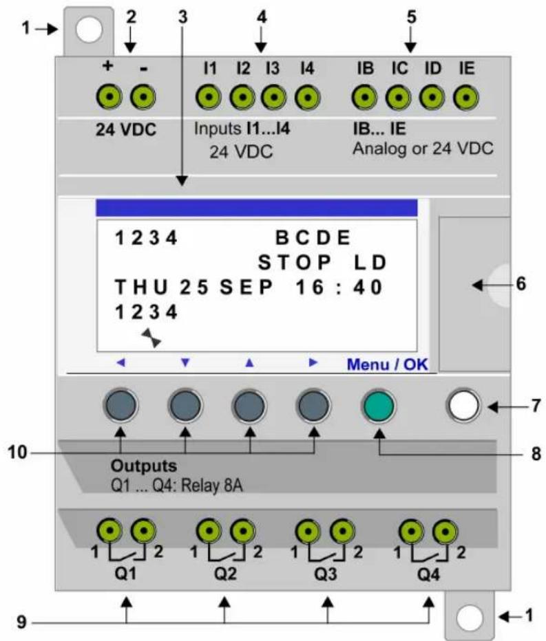
| Prompt Element |
| 1 Retractable mounting feet. |
| 2 Screw terminal block for the power supply. |
| 3 LCD display, 4 lines, 18 characters. |
| 4 Screw terminal block for discrete inputs. |
| 5 Screw terminal block for analog inputs.0-10 Volts, usable as discrete inputs depending on the reference. |
| 6 Slot for backup memory or PC connection cable. |
| 7 Shift key (white). |
| 8 Menu/OK key (green) for selection and confirmation. |
| 9 Relay output screw terminal block. |
| 10 Navigation keys (gray) or, alternatively, can be configured as Z keys. |
Description of the LCD
The illustration below presents an example of LCD display elements when displaying the INPUT-OUTPUT screen:
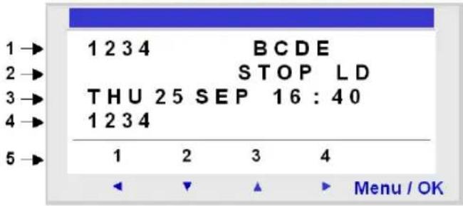
| Prompt Element | |
| 1 Input | status display (B...E represent the analog inputs).NOTE: An ACTIVE input or output is displayed in reverse video. |
| 2 Display of the operating mode (RUN/STOP) and programming type (LD/FBD). | |
| 3 Display of the date (day and time for products with clock). | |
| 4 Output status display. | |
| 5 | Contextual menus / pushbuttons / icons indicating the operating modes. |
Characteristics and Connections
Introduction
Here is detailed information on the characteristics of DC smart relay connections.
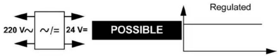
Connection to a Regulated DC Power Supply
Connect the smart relay to a regulated DC power supply:
Connection to a Rectified Filtered Regulated Power Supply
It is also possible to connect the smart relay to a rectified filtered regulated power supply:
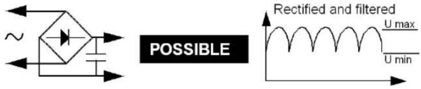
Comply with the following characteristics, according to the type of smart relay:
| SR2 ... BD SR2 ... JD | |
| U max < 30 V | U max < 14,4 V |
| U min > 19.2 V | U min > 10.4 V |
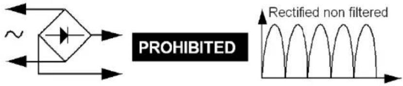
Prohibited Connection
It is prohibited to connect the smart relay to a rectified non-filtered power supply:
Control Keys on the Front Panel of the Smart Relay
Description
The keys located on the front panel of the smart relay are used to configure, program and control the application and monitor the application's progress.
Illustration:
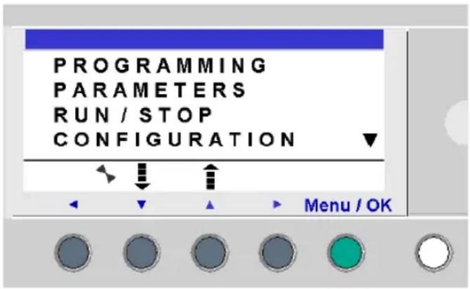
NOTE: The LCD screen is illuminated for 30 seconds when a key is pressed on the front panel.
Shift Key
The Shift key is the white key located on the right side of the LCD screen.
When the Shift key is pressed, a contextual menu is displayed above the Z keys.
Menu/OK Key
The Menu/OK key is the green key located below the LCD screen on the right side.
This key is used for confirmation of a menu, sub-menu, program, parameter, etc.
Zx Keys
The Zx keys are the gray keys aligned from left (Z1) to right (Z4) and located under the LCD. The arrows indicating the movement direction associated with navigation are marked above the keys.
The navigation keys are used to move left or right, down or up.
The position on the screen appears as a flashing zone:
- Square for a position that corresponds to a contact (only in programming menu),
- Round for a link (only in programming menu).
NOTE: When the keys may be used for other actions apart from navigation, a contextual menu bar is displayed (e.g.: 1, 2, 3 and 4 as Zx-type keys).
Contextual Menus
When the cursor is placed on a modifiable parameter, if the Shift key is pressed, a contextual menu appears.
Illustration:

Using the contextual menu functions:
-
- / -: Used to scroll through the various possible values of the selected field (types of inputs, outputs, automation functions, numbers, numerical values, etc),
- Ins.: Inserts a line,
- Del.: Deletes the selected element, or the entire line if it is empty,
- Param.: Displays the specific parameter screen for the automation function (visible only if the automation function contains a parameter),
- : Direction of the connection (available only if the cursor is placed over a link box),
- 1 2 3 4: This line appears when the keys are used as Zx key-type inputs in a program.
Password Protection Illustration:

The key indicates that the program is password-protected.
Other Condition Illustration:
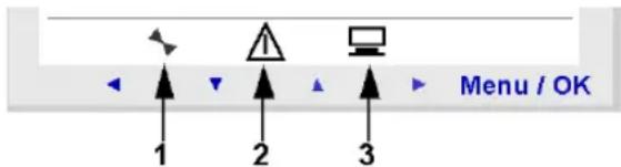
1: Indicates the state of the smart relay. In RUN it is in motion, in STOP it is immobile.
2: Indicates that errors have been detected.
3: The smart relay is physically connected to the programming software.
Examples
Introduction
We will now see two examples of how to use the smart relay keys.
Language Selection
Example 1: Here are details on how to select the language of the smart relay:
| Step Action | |
| 1 Apply | powerOn initial powering-up, the INPUT-OUTPUT screen is displayed (See: Inputs-Outputs Screen, page 38). By default, the selected language is English.Illustration: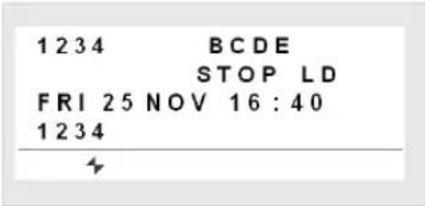 |
| 2 |  From the INPUT-OUTPUT screen, enter the MAIN mer to the CONFIGURATION menu LANGUAGE, by pressing 7 times on the down From the INPUT-OUTPUT screen, enter the MAIN mer to the CONFIGURATION menu LANGUAGE, by pressing 7 times on the down navigation keyIllustration: navigation keyIllustration: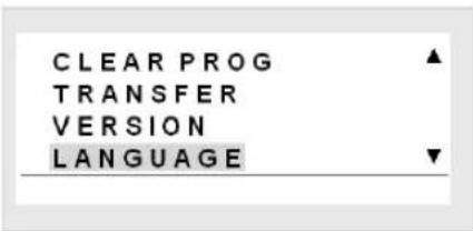 Note: the selected command flashes. Note: the selected command flashes. |
3 Enter in the language selection menu.  Illustration: Illustration: 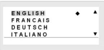 Note: The activated option flashes and it is also indicated by a black diamond. Note: The activated option flashes and it is also indicated by a black diamond. | |
4 Select and confirm the language (the selection is shown in flashing text).  The Menu/OK key is used to confirm the selection of the new language. The display returns to the MAIN menu when the smart relay is in STOP mode. Illustration: The Menu/OK key is used to confirm the selection of the new language. The display returns to the MAIN menu when the smart relay is in STOP mode. Illustration: 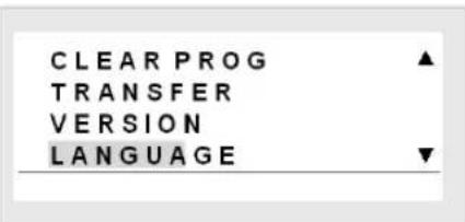 | |
Modification of Date and Hour
Example 2: Here are details on procedure to follow to modify the date and time.
| Step Action | |
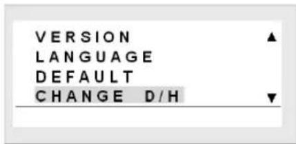
| 1 | From the INPUT-OUTPUT screen, enter the MAIN menu, then go to the CHANGE D/H menu: Menu / OK then 9 times in LD mode 7 times in FBD mode Illustration: VERSION LANGUAGE DEFAULT CHANGE D/H ▼ |
| 2 Enter | the date and hour configuration menu: Illustration: Illustration: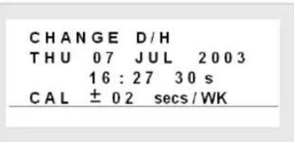 |
Step Action
3 Select the parameter to modify using the arrows (the selection is highlighted by the flashing of the parameter):
Modify the parameter using the navigation keys:
Then confirm with the Menu/OK key:
The Menu/OK key is used to confirm the modifications. The display returns to the MAIN menu when the smart relay is in STOP mode). Illustration:
| Step Action | |
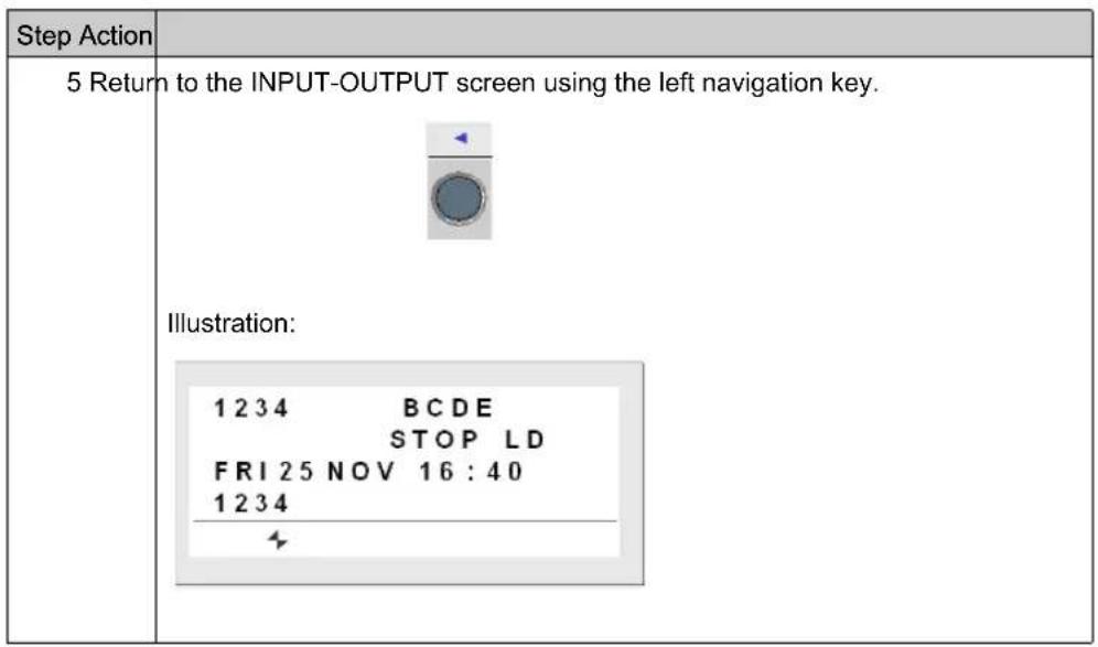
| 4 Return to the INPUT-OUTPUT screen Illustration: 1234 BCDE STOP LD FRI 25 NOV 16 : 40 1234 | |
Part II
Functions Accessible from the Front Panel
Subject of this Section
This section describes the functions that can be accessed from the front panel of the smart relay.
What Is in This Part?
This part contains the following chapters:
| Chapter Chapter Name Page | ||
| 2 Overview of the Functions Accessible from the Front Panel 35 | ||
| 3 Input/Output Screen 37 | ||
| 4 PROGRAMMING Menu 43 | ||
| 5 PARAMETERS Menu 55 | ||
| 6 MONITORING Menu 57 | ||
| 7 RUN/STOP Menu 59 | ||
| 8 CONFIGURATION Menu 61 | ||
| 9 CLEAR PROGRAM Menu 69 | ||
| 10 TRANSFER Menu 71 | ||
| 11 VERSION Menu 75 | ||
| 12 LANGUAGE Menu | 77 | |
| 13 DEFAULT Menu | 79 | |
| 14 CHANGE DATE/TIME Menu | 83 | |
| 15 CHANGE SUMMER/WINTER Menu | 85 | |
Chapter 2
Overview of the Functions Accessible from the Front Panel
Functions Accessible from the Front Panel of the Smart Relay
Description
From the front panel of the smart relay, you may:
• Program (in LD mode),
- Configure,
• Control the application,
- Monitor the performance of the application.
Illustration:
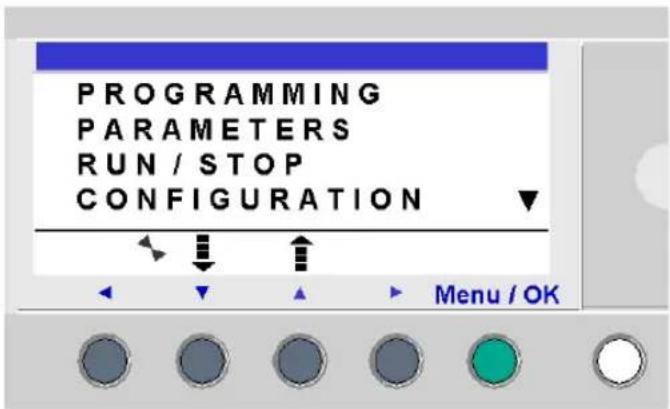
The line flashes to indicate where you are positioned.
The up triangle ▲ on the right side of the LCD screen indicates that possible up options exist. The down triangle ▼ indicates that possible down options exist.
To return to the previous menu, press left navigation key.
NOTE: The LCD screen is illuminated for 30 seconds when a key is pressed on the front panel.
Managing Menus
The inputs-outputs screen is displayed by default whether the mode be LD or FBD.
Pressing the Menu/OK key switches the display from the inputs-outputs screen to the main menu.
The menu on the first row which is selected by default (flashing). The ↓ and ↑ navigation keys can be used to place the cursor over the other menus.
Press the green Menu/OK key to display the screen corresponding to the selected menu or to move onto the first sub-menu.
Differences Between LD and FBD Modes
Certain menus are specific to either LD or FBD mode.
| Menu LD FBD | |||
| PROGRAMMING | √ | ||
| MONITORING | √ | ||
| PARAMETERS | √ | √ | |
| RUN / STOP | √ | √ | |
| CONFIGURATION | |||
| PASSWORD | ORD | √ | √ |
| F I L T E | √ R | √ | |
| Zx KEYS | √ | ||
| WATCHDOG CYCLE | √ | √ | |
| CLEAR PROG. | √ | ||
| TRANSFER | √ | √ | |
| VERSION | √ | √ | |
| LANGUAGE | √ | √ | |
| DEFAULT | √ | √ | |
| CHANGE D/T | √ | √ | |
| CHANGE SUMM/WINT | √ | √ | |
Configuring Extensions
Extensions added to the smart relay may only be configured from the programming software. See on-line help of the programming software for more information.
Chapter 3
Input/Output Screen
Subject of this Chapter
This chapter describes the characteristics of the input-output screen.
What Is in This Chapter?
This chapter contains the following topics:
| Topic Page | |
| Inputs-Outputs Screen 38 | |
| TEXT and DISPLAY screen 40 |
Inputs-Outputs Screen
Description
The inputs-outputs screen is the highest-level interface. It is displayed by default, when no (TEXT or DISPLAY) display function is active and regardless of:
• the programming type: LD or FBD,
• the operating mode: STOP or RUN.
Illustration:
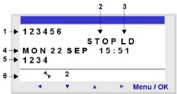
The inputs-outputs screen can be used to view:
- The state of the inputs: 1 to 9, A to P,
- The operating mode: RUN / STOP,
- The programming type used: LD/FBD,
- The date and time for products with a clock,
- The state of outputs: 1 to 9, A to G,
- Z keys: 1 to 4.
In Simulation mode or Monitoring mode when the program is in RUN, the active states of the inputs and outputs are indicated in reverse video.
Access to the Main Menu
Pressing the Menu/OK key switches the display from the inputs-outputs screen to the main menu:
• PROGRAMMING (LD STOP mode),
• MONITORING (LD RUN mode),
• PARAMETERS,
- RUN / STOP,
- CONFIGURATION (STOP mode),
- CLEAR PROG. (LD STOP mode),
• TRANSFER (STOP mode),
- VERSION,
- LANGUAGE,
- DEFAULT,
- CHANGE D/T,
- CHANGE SUMM/WINT.
The display automatically returns to the inputs-outputs menu on exiting other menus and sub-menus.
TEXT and DISPLAY screen
Description
The display functions are used to display text or numerical values (current value, preset value, etc.) on the LCD display instead of the INPUTS-OUTPUTS states.
Illustration:
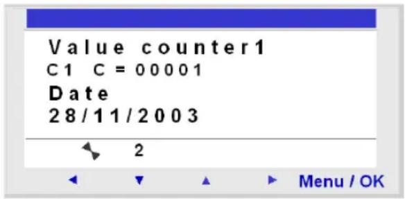
NOTE: The display functions are programmable only from the programming software (see the online help for the programming software for more information) in LD mode for the TEXT function, in LD mode or FBD mode for the DISPLAY function.
Switching Between the Screens
It is possible to go from the TEXT or DISPLAY screen to the INPUTS-OUTPUTS screen and vice-versa. Proceed as follows:
| Step Action | |
| 1 | Press and hold down the Shift key and press the Menu/OK key. |
Modify Displayed Values
In RUN mode, when the TEXT / DISPLAY screen is displayed, it is possible to modify, from the front panel, the displayed values whose modification was authorized in the block function parameters window.
To do this, proceed as follows:
| Step Action | |
| 1 Press | the Shift key (white key).Result: Param is displayed at the bottom of the screen. |
| 2 | Press the ► key (without releasing the Shift key) to display the contextual menu.Result: The parameter which can be modified flashes and the following contextual menu is displayed: |
| 3 Select | the parameter to be modified using the navigation keys and (the value which is available for modification flashes). |
| 4 Modify | the parameter value with the + ( ) and - ( ) keys.▼ |
| 5 Confirm | the changes by pressing the Menu/OK key.Result: The display returns to the INPUTS-OUTPUTS screen or the TEXT / DISPLAY screen. |
Chapter 4 PROGRAMMING Menu
Subject of this Chapter
This chapter describes the characteristics of the PROGRAMMING menu specific to LD mode / smart relay in STOP mode.
This function lets you enter the ladder diagrams that will work on the smart relay.
This program is written only using a ladder diagram LD.
Illustration:
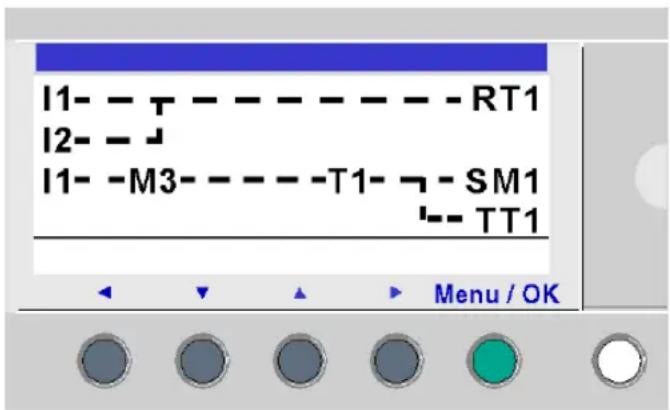
NOTE: The smart relays to which have been added an Input/Output extension are programmable only in FBD mode from the programming software.
See on-line help of the programming software for more information.
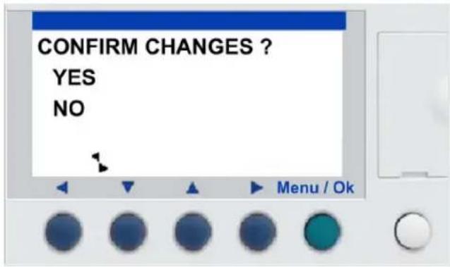
NOTE: In front panel programming with 240 lines, program memory is stored in two banks. One bank contains lines 1 to 120, and the other bank contains lines 121 to 240. You must do the program modifications in the first part (line 1 to 120) or in the last part (line 121 to 240) and save them before being able to modify the other part.
When the cursor moves from line 120 to 121, the front panel notifies you to save the modification (see picture below) and display the line 121. Then modification could be done on last part of the ladder.
When the cursor moves from line 121 to 120, the front panel notifies you to save the modification (see picture below) and display the line 120. Then modification could be done on first part of the ladder.
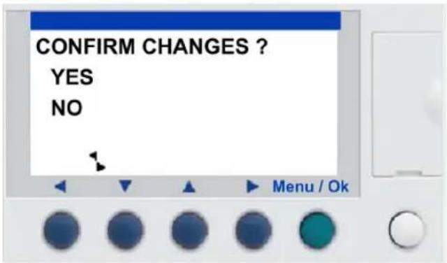
NOTE:
No link between the upper part (line 1 to 120) and the lower part (line 121 to 240) could be made in Ladder front panel programming:
- On line 120, it is not possible to insert a descending link (the descending link is displayed in the contextual menu but is ineffective).
- On line 121, it is not possible to insert a ascending link (the ascending link is displayed in the contextual menu but is ineffective).
- Insert a line in the upper part is possible only if line 120 is empty. If a line is inserted in upper part, the lower part is not modified.
- Delete a line in the upper part does not modify the lower part (line 121 does not move to line 120).
What Is in This Chapter?
This chapter contains the following topics:
| Topic Page | |
| Rules for Entering Ladder Diagrams 45 | |
| Method for Entering a Contact or Coil 47 | |
| Entering a Link 50 | |
| Entry of Function Block Parameters 52 | |
| Deletion and Insertion of Diagram Lines 53 |
Rules for Entering Ladder Diagrams
Description
The maximum number of lines in Ladder language that a smart relay allows you to enter is either:
- 120 lines, if an SR2COM01 communication interface has been selected in the configuration,
- 240 lines, without an SR2COM01 communication interface.
NOTE: The maximum number of program lines also depends on the firmware version (see page 186).
The smart relay's display screen is used to display these lines, 4 at a time, in the following manner:
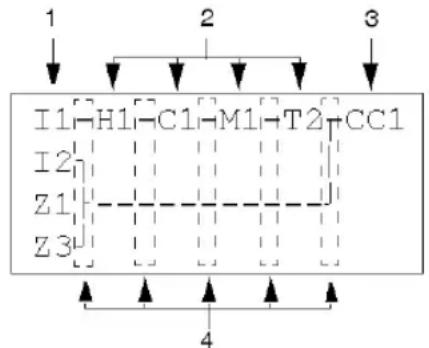
flowchart
graph TD
    A["1"] --> B["I1"]
    C["2"] --> D["H1"]
    E["3"] --> F["M1"]
    G["4"] --> H["T2"]
    I["5"] --> J["CC1"]
    K["6"] --> L["Z1"]
    M["7"] --> N["Z3"]
| Prompt Element |
| 1 Column reserved for contacts (conditions). |
| 2 Column reserved for contacts (conditions) and for links. |
| 3 Column reserved for coils (actions). |
| 4 Column reserved for links. |
Each line comprises 5 fields each with 2 characters reserved for contacts (conditions). The 4 central columns can also accept links. The last three-character column is reserved for coils (actions).
Links must be entered between the contact and coil columns.
A ladder diagram is entered into the smart relay using the front panel keys (see Control Keys on the Front Panel of the Smart Relay, page 25).
Data Entry Rules
Make sure you respect the following rules when you enter a ladder diagram:
| Rules Incorrect Correct | ||
| Each coil must only be entered once in the right hand column | 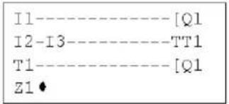 | 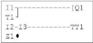 |
| Elements used as contacts may be entered as many times as necessary in the 5 left hand columns. | I1- - - - - - - TT1T1- - - - - - - [Q1I3-T1- - - - - - - - [M2I1-M2- - - - - - - - [Q2] | |
| Links must always run from left to right. | 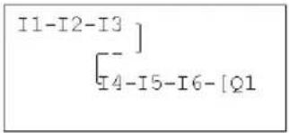 | 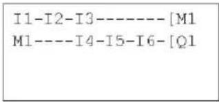 |
| If S coils (SET) are used in a diagram, also use an R (Reset) coil. | If no R (Reset) coils are used, the corresponding coil will always be set to 1. | An R (Reset) coil must be used for reset purposes. |
NOTE: Smart relays run programs from top to bottom and from left to right.
Method for Entering a Contact or Coil
Description
NOTE: Accessible only in LD mode / smart relay in STOP mode.
This section describes the procedures for performing the following operations:
- Entering an element,
- Modifying an element,
- Deleting an element.
This is valid for: contact or coil elements, whether the parameters can be set or not.
Entering an Element
When entering an element, the following rules must be observed:
- Contact: In any column except the last,
- Coil: Only in the last column.
The presence of a square, flashing cursor means an element can be inserted.
Entry procedure:
NOTE: Confirming some function block coils will bring-up a function block parameter setting screen.
| Step Action | |
1 Place the flashing cursor at the required location.The navigation keys can be used move the cursor in the direction of the arrows on the navigation keys ◀ ▼ ▲ ▶Illustration: | |
2 Press the Shift key to display the contextual menu. Illustration: By simultaneously pressing Shift and one of the ▼ ▲ (- and +) keys, the first letter of the element is inserted: I for a contact and Q for a coil, followed by the number 1. By simultaneously pressing Shift and one of the ▼ ▲ (- and +) keys, the first letter of the element is inserted: I for a contact and Q for a coil, followed by the number 1. | |
| 3 | Choose the type of element desired by pressing simultaneously on Shift and + or -. This makes the different types of elements scroll down cyclically, in the following order:For the contacts: I, i, Z, z, N, n, M, m, Q, q, T, t, C, c, K, k, V, v, A, a, H, h, W, w, S, s.For the coils: M, N, Q, T, C, K, X, L, S.See the chapter LD Language Elements, page 89. |
| 4 | Release the Shift key to have access to the navigation keys:◀ ▼ ▲ ▶.Pressing the ▶ key places the cursor over the corresponding number 1. |
| 5 | Simultaneously hold down the Shift and + keys to increment the number of the element (2, 3, 4,..., 9, A, etc.).NOTE:The numbers for functional blocks are limited to the number of blocks of the type available in the smart relay. In the case of extensible smart relays, the inputs and outputs numbers are used to program the extension to maximum size.In entering a contact, once this step is completed, the entry is terminated.In entering a coil, you must additionally select the function of the coil. |
| 6 | Release the Shift key to have access to the navigation keys:◀ ▼ ▲ ▶. |
| 7 Steps | 7 to 9 are only necessary when entering a coil.Position the cursor on the function of the coil by pressing twice on the ▶ key. |
| 8 | Select the desired function by pressing simultaneously on the Shift key and the + or - key. This will scroll through the different coil functions available. |
| 9 | Release the Shift key to have access to the navigation keys:◀ ▼ ▲ ▶. |
Modifying an element
To modify an existing control diagram element:
- Position the pointer over the element to modify: Step 1 in the previous table,
- Select the desired new element: Steps 3 to 6.
Initialization
Status of contacts on program initialization:
- A normally open contact (direct state) is inactive,
- A normally closed contact (reverse state) is active,
Deleting an Element
To delete an element:
- Place the cursor over the element to delete
- Simultaneously press the Shift and Del (Menu/OK) keys.
Two scenarios are possible, depending on the position of the cursor at the time of the deletion:
- Cursor over an element: the element is deleted,
- Cursor over an empty position of the line: the line is deleted.
NOTE: Generally, the deleted element must be replaced by a link.
Entering a Link
Description
NOTE: Accessible only in LD mode / smart relay in STOP mode.
This section describes the procedures for performing the following operations:
- Entering/Modifying links between elements,
- Deleting links between elements,
- Replacing a link with a contact.
Entering/Modifying a Link
Links are entered exclusively using the round flashing cursor.
| Step Action | |
| 1 Place | the flashing cursor at the required location.The navigation keys can be used move the cursor in the direction of the arrows on the navigation keys ◀ ▼ ▲ ▶Illustration: |
| 2 Press | the Shift key to display the contextual menu. Illustration: |
| 3 | Trace connections by simultaneously pressing the Shift key and the navigation keys: ← ↑ ↓ → .Shift and → to trace a connection to the position of the next contact or to the coil at the end of the line.Shift and ↑ ↓ to trace perpendicular connections to the previous or next line.NOTE: You cannot add a perpendicular connection between lines 120 and 121. |
| 4 | Release the Shift key to have access to the navigation keys: ◀ ▼ ▲ ▶. |
| 5 Repeat | at the operation as many times as necessary to create a program. |
Deleting a Link
To delete a link, simply:
- Place the cursor over the element to delete.
- Simultaneously press the Shift and Del (Menu/OK) keys.
Two scenarios are possible, depending on the position of the cursor at the time of the deletion:
- Cursor over a link: The link is deleted,
• Over an empty position of the line: The line is deleted.
Replacing a Link with a Contact
Refer to the element entry procedure (see page 47).
Entry of Function Block Parameters
Description
NOTE: Accessible only in LD mode / smart relay in STOP mode.
When entering a control diagram, the parameters of the configurable automation functions must be completed.
The automation functions with parameters are the following:
• Auxiliary relays (see page 95) (latching),
- Discrete Outputs (see page 98) (latching),
- Clocks (see page 132),
• Analog Comparators (see page 127),
- Timers (see page 101),
- Counters (see page 110),
- Fast counters (see page 116).
Accessibility of parameters
Function block parameter setting can be accessed:
- When entering the command diagram line,
- From the PARAMETERS menu if the block has not been padlocked.
Entering/Modifying Parameters of the Block
Parameters are entered in the same way, whatever the parameters screen:
| Step Action | |
| 1 Place | the flashing cursor at the required function.When the function has parameters,Paramappears in the contextual menu (when the Shift key is pressed).Illustration: |
| 2 | Press and hold down theShift key and press onParam(key ▶).Result:The function’s parameter screen appears. |
| 3 Use | the navigation keys to move to the cursor over the modifiable parameters: . ◀ ▶ |
| 4 | Modify the value of the parameter using the + and - keys, holding down Shift. |
| 5 Confirm | The modifications by pressing Menu/OK, which will open the confirmation window.Confirm again by pressing the Menu/OK key to save. |
Deletion and Insertion of Diagram Lines
Introduction
NOTE: In front panel programming with 240 lines, program memory is stored in two banks. One bank contains lines 1 to 120, and the other bank contains lines 121 to 240. You must do the program modifications in the first part (line 1 to 120) or in the last part (line 121 to 240) and save them before being able to modify the other part.
When the cursor moves from line 120 to 121, the front panel notifies you to save the modification (see picture below) and display the line 121. Then modification could be done on last part of the ladder.
When the cursor goes from line 121 to 120, the front panel notifies you to save the modification (see picture below) and display the line 120. Then modification could be done on first part of the ladder.
NOTE:
No link between the upper part (line 1 to 120) and the lower part (line 121 to 240) could be made in Ladder front panel programming:
- On line 120, it is not possible to insert a descending link (the descending link is displayed in the contextual menu but is ineffective).
- On line 121, it is not possible to insert a ascending link (the ascending link is displayed in the contextual menu but is ineffective).
- Insert a line in the upper part is possible only if line 120 is empty. If a line is inserted in upper part, the lower part is not modified.
- Delete a line in the upper part does not modify the lower part (line 121 does not move to line 120).
Deletion
NOTE: Accessible only in LD mode / smart relay in STOP mode.
Diagram lines are deleted line-by line. The procedure is the following:
| Step Action | |
| 1 Place the cursor over the line to delete. | |
| 2 Delete all the elements in the line (see page 47): (Links, contacts and coils) to obtain an empty line. | |
3 Press the Shift key to display the contextual menu.Illustration: Simultaneously pressing Shift and Del opens the confirmation window. Simultaneously pressing Shift and Del opens the confirmation window. | |
| 4 Confirm by pressing Menu/OK. | |
NOTE: It is possible to delete all diagram lines contained in the smart relay. In order to do this, select the CLEAR PROG. option from the main menu, and confirm the deletion of all the control diagram lines.
Insertion
The procedure is the following:
| Step Action | |
| 1 Place | the cursor over the line located immediately below the line to create. |
| 2 Press | the Shift key to display the contextual menu. |
| 3 | Press the Ins key (while holding down the Shift key) to create the line. |
Chapter 5 PARAMETERS Menu
PARAMETERS Menu
Description
This menu is used to enter and modify the application parameters directly on the screen using the smart relay keys. This function can be accessed in the two modes: LD and FBD, but the contents will be specific to the mode used.
If there are non-locked parameters to display they are listed in the window; otherwise a NO PARAMETER message appears.
LD Mode
Functions with parameters in LD mode:
• Auxiliary relays (see page 95) (latching),
- Discrete Outputs (see page 98) (latching),
- Clocks (see page 132),
• Analog Comparators (see page 127),
- Timers (see page 101),
- Counters (see page 110),
- Fast counter (see page 116).
Only those functions used in the program and with parameters are listed in the PARAMETERS menu.
FBD Mode
Functions with parameters in FBD mode:
• Numerical Constant-Type Inputs,
- Clocks,
- Gain,
- Timers: TIMER A/C, TIMER B/H, TIMER Li,
- Counters: PRESET COUNT,
- Fast counter,
- CAM block.
To access the parameters of the FBD blocks, you must enter the block number. This number appears in the programming software on the wiring sheet at the top right corner of the block.
Only those functions used in the program and with parameters are listed in the PARAMETERS menu.
Parameter Modification
Parameter modification procedure:
| Step Action | |
| 1 Place | the cursor over the PARAMETERS menu in the main menu (PARAMETERS flashing) and confirm by pressing the Menu/OK key.Result: The parameters window opens to the first parameter. |
| 2 Select | the function to modify.To access the required function, scroll through the function block numbers (navigation keys ▼and ) until you reach the one to edit. |
| 3 Select | the parameter to modify.The ▼and keys are used to place the cursor over the parameter to modify. |
| 4 | Modify the parameter using the + and - keys (▲ and ▼) of the contextual menu. |
| 5 | Confirm the modifications by pressing Menu/OK, which will open the confirmation window. |
| 6 Confirm | again twice by pressing Menu/OK to save.Result: The display returns to the INPUTS-OUTPUTS screen in RUN mode and to the MAIN menu in STOP mode. |
Parameters in RUN Mode
It is possible to modify parameters in RUN mode as long as they are not locked.
The modifications can be made:
- From the PARAMETERS (see page 55) menu,
- From the MONITORING (see page 57) (LD) menu: Move the pointer over the function to be modified using the navigation keys and open the parameters window from the contextual menu (Shift key).
Chapter 6 MONITORING Menu
MONITORING Menu
Description
NOTE: Accessible only in LD mode / smart relay in RUN mode.
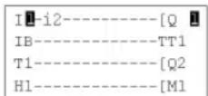
MONITORING mode can be used to obtain a dynamic view of the state of the smart relay inputs/outputs.
In this mode the wiring grid appears as it does in the PROGRAMMING(see page 43) menu (smart relay in STOP mode), but appear in reverse video when inputs or outputs are activated (white on black background).
Illustration:
This mode is also used to dynamically modify the values of automation function parameters if these are not locked.
Parameter Modification
To modify the parameters, proceed as follows:
| Step Action | |
| 1 Use the navigation keys to move the cursor over the element to modify. | |
| 2 | Hold down Shift key then press the Param key to open the parameter window. |
| 3 Use the navigation keys to move to the cursor over the modifiable parameters: . | |
| 4 | Change the parameter value using the keys + and -. |
| 5 Confirm the modifications by pressing Menu/OK, which will open the confirmation window. Confirm a second time by pressing Menu/OK to save. | |
| 6 Confirm again with Menu/OK. Result: Return to the parameter screen. | |
| 7 Confirm again with Menu/OK. Result: Return to the LD diagram screen. | |
Chapter 7 RUN/STOP Menu
RUN/STOP Menu
Description
This function is used to start or stop the program in the smart relay:
- In STOP mode: The program is stopped and the outputs disabled,
- In RUN mode (with or without initialization of latching parameters): The program is executed
NOTE: The outputs of an extension SR3XT43BD are not disabled if an acceleration time is specified in the extension parameters.
Startup
In STOP mode, when accessing the RUN/STOP menu, the interface proposes the following three choices for starting the program:
- WITH NONVOLAT INI: All values (counters, timers, etc.) are reset to their initial values before the program starts (default selection),
- NO NONVOLAT INI: Values for which the Latching option has been activated are kept,
• NO: The program does not start.
Illustration:
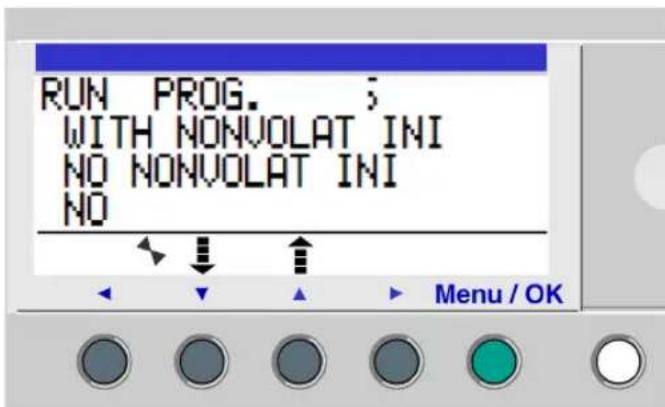
The navigation keys are used to change the selection.
When the setting has been validated with the Menu/OK key, the display moves to the INPUT-OUTPUT screen.
Off
In RUN mode, when accessing the RUN/STOP menu, you need to confirm the request to stop the program:
- YES: The program stops (selected by default),
• NO: The program does not stop.
Illustration:
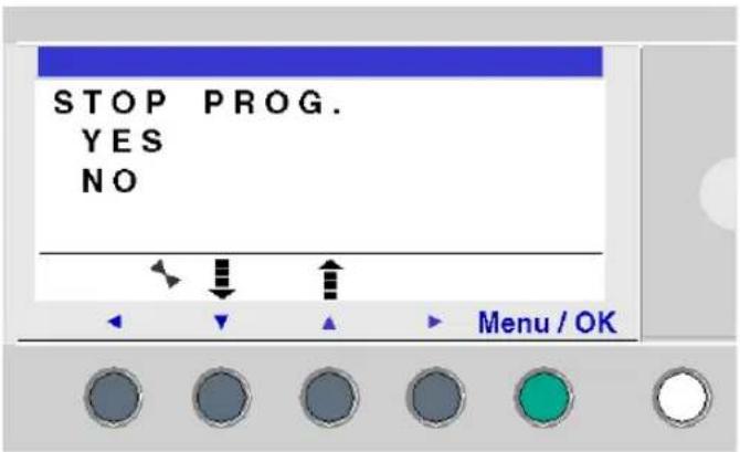
The navigation keys ▼ are used to change the selection.
When the setting has been confirmed with the Menu/OK key, the display moves to the INPUT-OUTPUT screen.
Smart Relays Without Screen
For smart modules without screen, a green LED located on the front panel of the module is an indicator light:
- If the LED flashes slowly (3 Hz), the module is in RUN mode (even if there is a recoverable error detected).
- If the LED flashes rapidly (5 Hz), the module is in STOP mode with an error detected.
- If the LED stays illuminated, the module is powered-up and in STOP mode.
NOTE: On power up, the smart relay is in RUN mode, unless there is an error detected.
NOTE: When an error has been detected, eliminate the source of the error and power cycle the module.
Chapter 8 CONFIGURATION Menu
Subject of this Chapter
The CONFIGURATION menu provides access to the following 4 functions:
- PASSWORD,
- FILTER,
- Zx KEYS,
- WATCHDOG & CYCLE
This chapter describes the characteristics of these functions.
NOTE: Use the navigation key to return to the main menu
NOTE: If the program is password-protected, (key displayed in the contextual menu), the user must enter the password before any action can take place in the sub-menus.
NOTE: The CONFIGURATION menu is only available in STOP mode.
What Is in This Chapter?
This chapter contains the following topics:
| Topic Page | |
| PASSWORD Menu 62 | |
| FILTER Menu 65 | |
| Zx KEYS Menu 66 | |
| WATCHDOG CYCLE Menu 67 |
PASSWORD Menu
Description
If the program is password-protected (key icon appears), you must enter the password to perform certain operations.
The password protects access to the following menus:
• PROGRAMMING (LD STOP mode),
• MONITORING (LD RUN mode),
- CONFIGURATION (STOP mode),
- CLEAR PROG. (LD STOP mode),
- MODULE TRANSFER > MEM (STOP mode).
- MEM TRANSFER > MODULE (STOP mode). In LD mode, password protection of this menu is configurable.
NOTE: If you lose a password, you can overwrite the program from the programming software; see the on-line help of the programming software.
NOTE: It is possible to quit the screen without entering a password. Hold down Shift key (white key) then press the Menu/OK key (green key).
NOTE: To return to the main menu from the CONFIGURATION menu, use the navigation key ◀.
Defining Password
Initially, the key is not displayed and each digit is set to 0.
The ENTER message appears in the window.
Illustration:
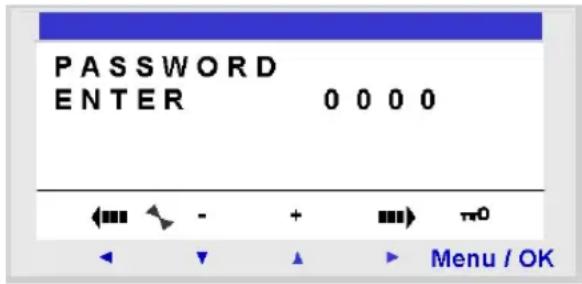
Entry procedure:
| Step Action | |
| 1 Use the navigation keys to select the digit to enter: . | |
| 2 | Select the value of the digit using the + and - keys of the contextual menu. |
| 3 | Confirm the password with the Menu/OK key, which opens the confirmation window. |
| 4 Confirm again with the Menu/OK key.Result: The display returns to the MAIN menu. | |
NOTE: Henceforth the key is displayed in the contextual menu line.
Removing Password
To inhibit the password, follow the same procedure used to enter it.
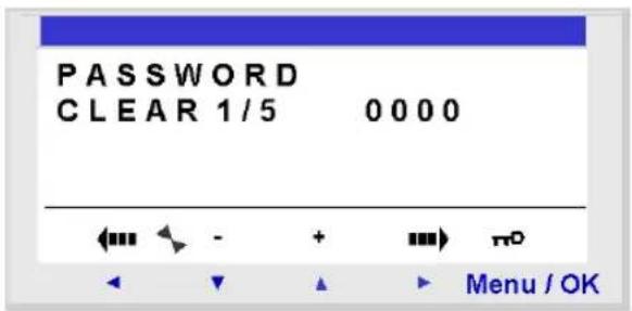
Initially, the key icon is displayed, meaning: Smart relay protected.
The message CLEAR and the number of attempts 1 / 5 appear in the window.
The following scenarios may arise:
- Password correct: The password is then inhibited, and the smart relay returns to the PASSWORD menu,
- Password incorrect: The CLEAR counter is incremented.
Illustration:
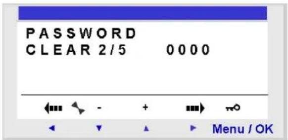
If an incorrect password is entered 5 times consecutively, the security function is locked for 30 minutes.
During this period, if the power supply to the smart relay is interrupted, the downcount will start again on power up.
Illustration:
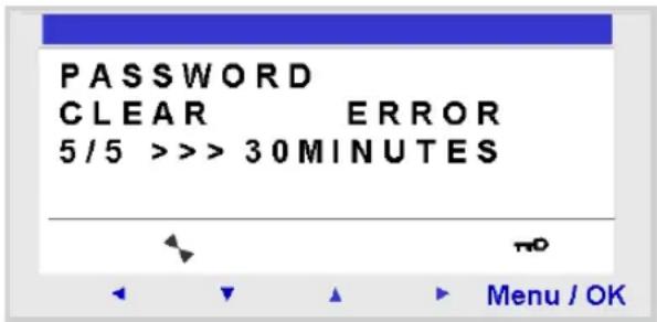
Modifying Password
To modify the password, remove the password and then enter a new one.
FILTER Menu
Description
This function is used to set the filter time of the inputs. A fast filter detects an input signal change faster than a slow filter; however, a fast filter is more sensitive to disturbances such as signal bounce.
Two choices are available:
- Fast
- Slow
Response time:
| Filtering Commutation Response time | |
| Slow ON → OFF | 5 milliseconds |
| OFF → ON 3 milliseconds | |
| Fast ON → OFF | 0.5 milliseconds |
| OFF → ON 0.3 milliseconds | |
This selection can only be made when the smart relay is in STOP. By default, the smart relays are configured in SLOW.
NOTE: This function is available on smart relays with a direct voltage power supply.
NOTE: To return to the main menu from the CONFIGURATION menu, use the navigation key ◀.
Filter-Type Selection
The type is indicated by the selection symbol (black diamond).
Procedure for selection of filter type:
| Step Action | |
| 1 | Select the type of filtering using the ▼▲ keys (the selection will flash). |
| 2 Confirm with Menu/OK.Result: the display returns to the MAIN menu. | |
Zx KEYS Menu
Description
NOTE: Only accessible in LD mode.
The Zx KEYS option is used to activate or deactivate the use of the navigation keys as pushbuttons.
Different functions can be obtained depending on the state of this option:
- Inactive: The keys are only available for setting, configuring and programming the smart relay.
• Active: they can also be used in a control diagram.
In this configuration, they operate as pushbuttons: Zx keys (see page 93), without the need to use a terminal input contact.
NOTE: To return to the main menu from the CONFIGURATION menu, use the navigation key ◀.
Zx Keys in RUN Mode
By default, the Zx keys are used as navigation keys.
In RUN mode, when the inputs-outputs screen, TEXT screen or DISPLAY screen is active, the numbers of the Zx keys used in the program are displayed in the contextual menu line.
To activate the key, simply select the required key ◀ ▼ ▲ ▶
Illustration:
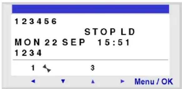
NOTE: The function is inactive in Parameters mode, Monitoring and all the function block parameter and configuration screens.
WATCHDOG CYCLE Menu
Description
The duration of a program cycle depends on its length and complexity; in particular, the type and number of I/O and the number of extensions.
The program is executed periodically at regular time intervals. This time interval is called the cycle time.
The program will only execute completely if the cycle time is greater than the program execution time.
The cycle period is configurable in the CONFIGURATION → WATCHDOG CYCLE menu. This period may be set from 6 to 90 milliseconds in 2-millisecond steps.
The default value of the cycle period is 14 milliseconds.
Illustration:
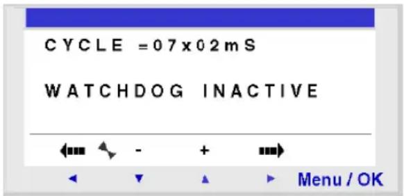
NOTE: Make sure that:
- Input variations that are too rapid are not hidden by a cycle time that is too slow.
- The speed of output variations is compatible with system commands.
If the duration of the execution cycle of the program and the embedded software functions exceeds the cycle time value selected by the programmer, the WATCHDOG can be used to operate a specific action.
NOTE: In certain dialog phases, the cycle times are increased by the communication times between the PC and the smart relay. The real cycle times vary greatly during this operating mode. The WATCHDOG is always inhibited in this smart relay operating mode.
NOTE: To return to the main menu from the CONFIGURATION menu, use the navigation key ◀.
Actions
The WATCHDOG can perform the following actions:
• INACTIVE: Normal operation
- ALARM: An error condition is set and the error code corresponding to Cycle time overrun is accessible in the DEFAULT menu.
- ERROR: The program stops (STOP mode) and the error code corresponding to Cycle time overrun is accessible in the DEFAULT menu.
Cycle Time
The cycle time may be set from 6 to 90 milliseconds in 2-millisecond steps.
To adjust this period, adjust the 2-millisecond step multiplier factor using the + and - keys in the contextual menu. This factor is between 3 and 45.

The multiplier factor is adjusted depending on the shortest sampling period of the inputs.
WATCHDOG Configuration
Procedure:
| Step Action | |
| 1 | Configure the CYCLE parameter using the + and - keys in the contextual menu. |
| 2 Confirm the entry using one of the following keys: or . ◀ Result: The CYCLE parameter is confirmed and the WATCHDOG parameter is selected (it flashes). | |
| 3 | Configure the WATCHDOG parameter using the + and - keys in the contextual menu. |
| 4 Confirm your changes by pressing the Menu/OK key.Result: The display returns to the MAIN menu. | |
Chapter 9
CLEAR PROGRAM Menu
CLEAR PROG Menu.
Description
NOTE: Accessible only in LD mode.
This function is used to clear the entire program.
NOTE: If the program is protected (key displayed), the user must enter the password (see PASSWORD Menu, page 62) before being able to delete the program.
Clearing the Program
On opening, NO is selected by default.
Procedure:
| Step Action | |
| 1 Select the YES choice using the navigation keys and ▼ ▲ | |
| 2 Confirm the clear command by pressing the Menu/OK key.Result: the display returns to the MAIN menu. | |
Chapter 10
TRANSFER Menu
TRANSFER Menu
Description
This function is used to:
- Load the firmware and the application contained in the smart relay into the backup memory.
- load firmware and application from the backup memory to the smart relay.
This backup memory can then be used to load the firmware and the application into another smart relay.
Illustration:
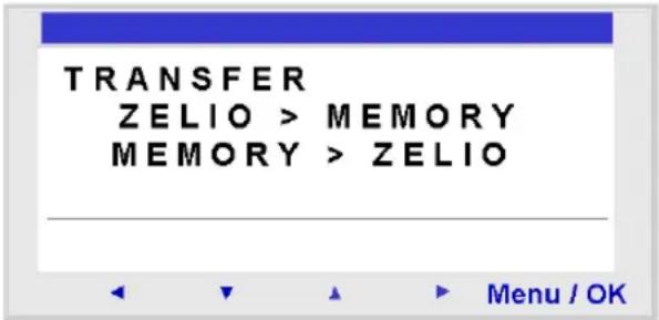
NOTE: The backup memory is provided as an option.
NOTE: Insertion and extraction of the backup memory may be performed even when the smart relay is powered up.
For smart relays without screens, detection of the memory may only be performed on power up of the smart relay, if the memory is inserted when the smart relay is powered on, it will not be acknowledged.
NOTE: If the application is protected (key icon displayed), you must enter the password before being able to save the program.
NOTE: If an application is already present in the backup memory, it will be overwritten by the new transfer.
NOTE: It is not possible to directly transfer an application created with version V2 of the programming software from the SR2MEM01 memory to the smart relay if this latter contains version V3 firmware.
In this case, see what action you should take in the section Application incompatible with firmware on the smart relay (see page 73).
For more information about the compatibility of the memory cartridges, see Compatibility between the memory cartridges and the firmware on the smart relay (see page 187).
Module → Backup Memory Transfer
Procedure for transferring the application from the smart relay to the backup memory, for a smart relay with LCD and keyboard:
| Step Action | |
| 1 Insert the memory cartridge (SR2MEM02) into the slot provided. | |
| 2 | Select the transfer type: ZELIO>MEMORY using the navigation keys ▼ ▲. |
| 3 Confirm the transfer command with the Menu/OK key.(Enter the password if the program is password-protected). | |
| 4 Wait for the transfer to end.Display: >>> MEMORY then TRANSFER. OK when it is completed. | |
| 5 Confirm again by pressing Menu/OK key to exit the menu.Result: The display returns to the INPUTS-OUTPUTS screen in RUN mode and to the MAIN menu in STOP mode. | |
NOTE: It is not possible to transfer the application from a smart relay without LCD or keyboard. You can transfer the module application to the PC using Zelio Soft.
Backup Memory → Module Transfer
The program transfer from one smart relay to another via a memory card is only possible between smart relays with the same reference.
Procedure for transferring the application from the backup memory to the smart relay, for a smart relay with LCD and keyboard:
| Step Action | |
| 1 Insert | the memory cartridge (SR2MEM02) with the program to be transferred into the slot provided. |
| 2 | Select the transfer type: MEMORY>ZELIO using the navigation keys ▼ ▲. |
| 3 Confirm | the transfer command with the Menu/OK key. |
| 4 Wait | for the transfer to end.Display: >>> MODULE then TRANSFER. OK when it is completed. |
| 5 Confirm | again by pressing Menu/OK to exit the menu.Result: the display returns to the INPUTS-OUTPUTS screen in RUN mode and to the MAIN menu in STOP mode. |
Procedure for transferring the application from the backup memory to the smart relay, for a smart relay without LCD or keyboard:
| Step Action | |
| 1 | Since the smart relay is not powered-on, insert the memory cartridge (SR2MEM02) into the slot provided. |
| 2 Power up the smart relay.During the transfer, the LED display is off. | |
| 3 Wait for the transfer to end.During the transfer, the LED display is off, then at the end of the transfer the LED flashes. | |
| 4 | If the flashing is slow (3 Hz), the transfer has been successful, the smart relay is in RUN, remove the memory cartridge (SR2MEM02).If the flashing is rapid (5Hz), the transfer has been unsuccessful due to incompatibility between the configuration necessary for the program to be transferred and that of the smart relay. |
NOTE: When the smart relay is in STOP mode, the LED display is illuminated and does not flash.
Possible Errors
Below are the possible errors and, for each case, the messages that are displayed:
• Absence of backup memory
Error message:
TRANSFER ERROR: NO MEMORY
- Configurations of the hardware and program to transfer incompatible
Error message:
TRANSFER ERROR: CONFIG INCOMPAT (hardware or software reference numbers).
For more details, refer to the DEFAULT menu (seepage chapter.
Application incompatible with firmware on the smart relay
If the application stored in backup memory SR2MEM01 was created with a version of the programming software that is incompatible (see page 187) with the firmware of the target smart relay, proceed as follows:
| Step Action | |
| 1 Load | the application from the backup memory to a smart relay with compatible firmware. |
| NOTE: If no smart relay has a firmware that is compatible with the application, use the programming software version that was used to create the application to load a compatible firmware into the target smart relay. | |
| 2 Use | the version of the programming software that was used to create the application to load it from the smart relay toward the PC. |
| 3 Save | the application uploaded in step 2. |
| 4 Launch | the latest version of the programming software. |
| 5 Open | the application saved in step 3.Result: The programming software converts the application. |
| 6 Load | the converted application and the associated firmware to the target smart relay. |
Use of SR2MEM01 and SR2MEM02
On SR2MEM01, only the program is loaded whereas on SR2MEM02 the program and the corresponding firmware are loaded.
Consequently:
- With the SR2MEM01 memory cartridge, you can perform:
- A smart relay to memory transfer if the version of the firmware on this relay is strictly lower than 3.09.
- A memory to smart relay transfer if the program contained in the SR2MEM01 memory cartridge is loaded from a smart relay that has the same version of firmware as the smart relay to which you want to load the cartridge.
- With the SR2MEM02, memory cartridge, you can perform:
- A smart relay to memory transfer if the version of the firmware on this relay is equal to or greater than 3.09.
- A memory to smart relay transfer if the version of the firmware on the relay to which you want to load the cartridge is greater than 3.09.
For more information about the compatibility of the memory cartridges, see Compatibility between the memory cartridges and the firmware on the smart relay (see page 187).
Chapter 11 VERSION Menu
VERSION Menu
Description
This function is used to precisely identify the version of each system component:
- MODULE: smart relay reference,
- HARDWARE: hardware version,
• FIRMWARE: firmware version, - LD FUNC: language functional level if LD language or FBD FUNC: language functional level if FBD language.
Illustration:
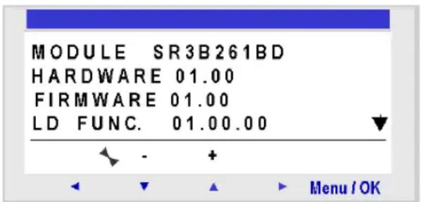
This information is available for the smart relay, but also for the connected extensions.
The ▼ symbol is present in the bottom right, indicating the existence of extensions connected to the smart relay.
Illustration:
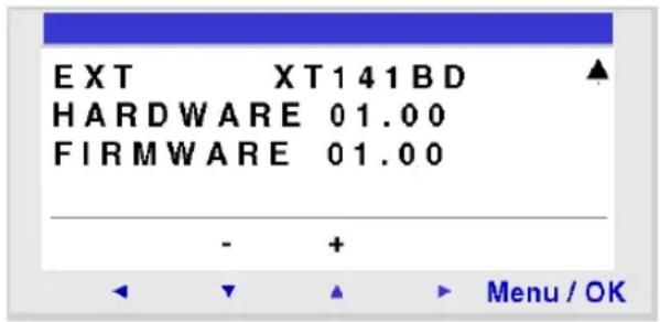
To quit, press the Menu/OK button, the display returns to the INPUTS-OUTPUTS screen if smart relay is in RUN mode and to the MAIN menu if smart relay is in STOP mode.
Chapter 12
LANGUAGE Menu
LANGUAGE Menu
Description
This function is used to select the language used by the smart relay.
All messages may be viewed in 6 languages:
- English,
- French,
- German,
- Italian,
- Spanish,
- Portuguese.
Illustration:
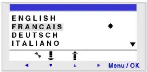
Language Selection
The current language is indicated by the selection symbol (black diamond).
Language selection procedure:
| Step Action | |
| 1 Select the language using the navigation keys: and ▼(the selection flashes). | |
| 2 Confirm with the Menu/OK key.Result: The display returns to the INPUTS-OUTPUTS screen in RUN mode and to the MAIN menu in STOP mode. | |
Chapter 13 DEFAULT Menu
DEFAULT Menu
Description
This function is used to:
- Display on the LCD screen the type of error detected by the firmware of the smart relay (Watchdog overrun, see WATCHDOG CYCLE Menu, page 67, cycle time too high, etc.),
- Reset the error counter to zero.
Illustration:
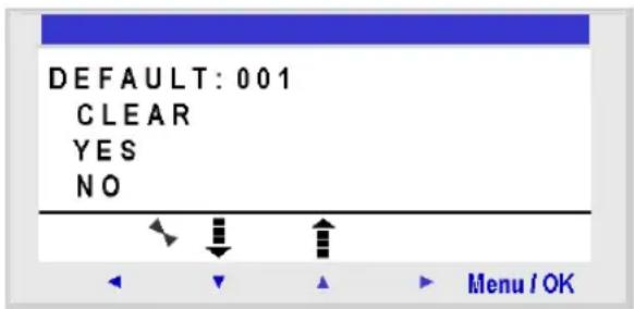
Reset to Zero of the Error Counter
To reset the error counter to zero, proceed as follows:
| Step Action | |
| 1 Select the YES choice using the navigation keys and ▼ ▲ | |
| 2 Confirm the clear command by pressing the Menu/OK key.Result: The display returns to the INPUTS-OUTPUTS screen in RUN mode and to the MAIN menu in STOP mode. | |
Error Types
Below, the description of possible errors:
| Code Type of error | |
| 000 No error | |
| 001 Error in writing to memoryThis error defines the transfer errors between the memory cartridge and the smart relay. If this error occurs frequently, contact your local Schneider Electric support representative. | |
| 002 Clock write errorIf the error occurs frequently, contact your local Schneider Electric support representative. | |
| 004 Overload on transistor outputsOnce a transistor output reaches the threshold for over current detection, the group of 4 outputs to which it belongs is deactivated.To make this group of outputs operational, the cause of the over current (short-circuit, etc.) must first be deleted, and then the error cleared from the DEFAULT menu (see page 79). | |
| 050 Smart relay firmware is corruptedReload the firmware on the smart relay and the user application. If this error persists, contact your local Schneider Electric support representative. | |
| 051 Watchdog overflowAdvisory or error according to the selection made in the menu (smart relay display) or in the configuration window (programming software).The cycle time in the smart relay is too short compared with the application program execution time programmed in the smart relay.If the application requires cycle time or strict sampling of the smart relay inputs/outputs, lengthen the application cycle time in the smart relay. To do this, either set the parameters in the CONFIGURATION menu (smart relay display) or in the configuration window (programming software).If the application does not require a maximum cycle time, you must choose: No WATCHDOG Action in the CONFIGURATION menu. | |
| 052 The smart relay has executed an incorrect operationIf the error is permanent, reload the firmware on the smart relay and the user application. If this error persists, contact your local Schneider Electric support representative. | |
| 053 Link error between smart relay and bus-type extensionVerify operation of the extension (connection, power supply, error status). | |
| 054 Link error between smart relay and input/output-type extensionVerify operation of the extension (connection, power supply and error status). | |
| 058 An error has been detected in the firmware (software specific to the smart relay) or on the smart relay hardware.If the error is permanent, reload the firmware on the smart relay and the user program. If this error persists, contact your local Schneider Electric support representative. | |
| 059 At the beginning of RUN on the smart relay application: The application cannot switch to RUN because it is incompatible with the smart relay physically connected to the power supply.If this error occurs, contact your local Schneider Electric support representative. | |
| 060 At the beginning of RUN on the smart relay application: Program incompatible with the bus extension physically connected to the power supply.If this error occurs, contact your local Schneider Electric support representative. | |
| 061 At the beginning of RUN on the smart relay application: Program incompatible with the Input/Output extension physically connected to the power supply.If this error occurs, contact your local Schneider Electric support representative. | |
| 062 Version (or build number) incompatibility when loading a program from the backup memoryIf this error occurs, contact your local Schneider Electric support representative. | |
| 063 Hardware configuration incompatibility when loading a program from the backup memoryIf this error occurs, contact your local Schneider Electric support representative. |
Chapter 14
CHANGE DATE/TIME Menu
CHANGE DATE/TIME Menu
Description
This function is used to configure the date and time of the smart relays that have a clock. Illustration:
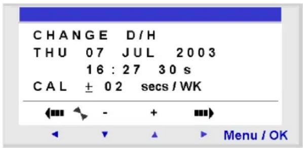
The modifiable parameters are:
• Day / week / month / year,
• Hour, minutes, seconds,
Values are recorded by pressing the Menu/Ok key.
- CAL: Calibration of the internal clock of the smart relay in seconds per week.
Clock Calibration
The quartz that controls the real-time clock of the smart relay has a variable monthly drift depending on the environmental conditions of the smart relay.
The maximum value for this drift is approximately one minute per month.
To estimate this drift, proceed by observing the drift on the smart relay clock with respect to a reference clock for a few weeks or more.
Example:
If you wish to compensate this drift, you can for example make a -15 second correction per week to compensate for a + 60 second drift per month. This compensation is executed on Sunday at 01:00.
NOTE: This correction serves no purpose if the smart relay is subject to long power interruptions or major variations in temperature.
Clock Configuration
Procedure:
| Steps Description | |
| 1 Select the parameter to modify using the navigation keys and Result: The selected parameter flashes. | |
| 2 Modify the value of the parameter.The + and - keys of the contextual menu can be used to change the current value. | |
| 3 Confirm the changes by pressing the Menu/Ok key.Result: The display returns to the MAIN menu. |
NOTE: The smart relay determines the day of the week when the day of the month in the year is selected.
NOTE: You cannot modify the hour by a product between 2:00 and 3:00 for the days of the change from summer to winter time.
Chapter 15
CHANGE SUMMER/WINTER Menu
CHANGE SUMMER/WINTER Menu
Description
This function is used to change the time range automatically: Summer/winter, for smart relays with a clock.
Illustration:
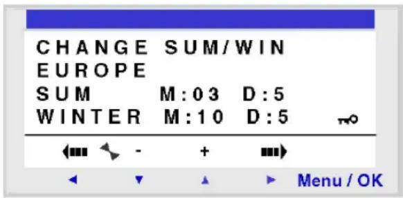
The following operating modes are possible:
- NO: no change,
- Automatic: The change takes place automatically, the dates are preset according to the geographic zone:
- EUROPE: Europe,
USA.
- OTHER ZONE: (MANUAL) the change takes place automatically, but you must specify, for summer and winter:
- The month: M, - The Sunday: D (1, 2, 3, 4 or 5) when the change takes place.
Configuration of the Time Change
To configure automatic time change, proceed as follows:
| Step Action | |
| 1 Select the parameter to modify using the navigation keys and Result: The selected parameter flashes. | |
| 2 Modify the parameter value.The + and - keys of the contextual menu are used to change the current value. | |
| 3 Confirm the changes by pressing the Menu/OK key.Result: The display returns to the MAIN menu. | |
Part III
LD Language
Chapter 16
LD Language Elements
Subject of this Chapter
This chapter describes the different automation functions of the LD language.
What Is in This Chapter?
This chapter contains the following topics:
| Topic Page | |
| Introduction 90 | |
| Discrete Inputs 91 | |
| Zx Keys 93 | |
| Auxiliary Relays 95 | |
| Discrete Outputs 98 | |
| Timers 101 | |
| Counters 110 | |
| Fast Counter 116 | |
| Counter Comparators 125 | |
| Analog Comparators 127 | |
| Clocks 132 | |
| TEXT 135 | |
| LCD Screen Backlighting 137 | |
| Change to Summer / Winter Time | 138 |
| Modbus Inputs/Outputs | 140 |
| Message 141 |
Introduction
Description
In LD programming mode, an application can be created from the interface of the front panel of the smart relay.
Here is detailed information on the possible elements of a ladder diagram in LD mode that are recognized and used by smart relays.
To illustrate the functions performed by each element, where necessary a directly usable example is included.
Composition of Ladder Diagrams
The maximum number of lines in Ladder language that smart relays accept depends on two factors:
• the firmware version
- whether an SR2COM01 communication interface has been selected in the configuration.
For detailed information, refer to the table presented in Smart Relay Firmware Version Versus Functions (see page 186).
Each program line comprises of a maximum of 5 contacts. Contacts must be attached to one coil, and the coil is not necessarily on the same program line.
NOTE: When an application requires more than five contacts to activate an action, the auxiliary relays may be used.
NOTE: Perpendicular connection is not possible between the lines 120 and 121.
Sample Ladder Diagram
Below is an example of a ladder diagram, as it appears on the display of the front panel of a smart relay:
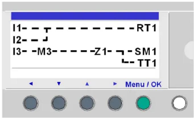
Discrete Inputs
Description
The Discrete Inputs can be used exclusively as contacts in the program.
These contacts represent the status of the input for the smart relay connected to a sensor (push button, switch, sensor, etc.).
The contact number corresponds to the number of terminals of the associated input: 1 to 9, then A to R (except for letters I, M and O) according to the smart relay and the possible extension.
Use as a Contact
This contact may use the direct state of the input (normally open contact) or its inverse state (normally closed contact), see below.
Normally open:
Symbol of a normally open contact:
1-
If the input is supplied, the contact is conducting.
Example:
1 — J Q1
If input 1 is supplied, contact I1 is closed, and coil Q1 is activated.
Normally closed:
Symbol of a normally closed contact:
i.
If the input is supplied, the contact is non-conducting.
Example:
i1 — [Q1
If input 1 is supplied, contact i1 is open, and coil Q1 is not activated.
Modification of the state of a contact
To modify a contact from the front panel of the smart relay (the programming window is displayed on the screen):
- Place the cursor over the letter of the contact,
- Scroll through the possible contact types (I for a normally open contact, i for a normally closed contact).
For more details, refer to Method for Entering a Contact or Coil (see page 47).
Initialization
Status of contacts on program initialization:
- The direct state is inactive,
• The reverse state is active.
Zx Keys
Description
The navigation keys behave like the I physical inputs (Discrete inputs). The only difference is that they do not correspond to smart relay connection terminals, but to the four gray keys on the front panel.
They are used as pushbuttons, and can only be used as contacts.
Use as a Contact
This contact may use the direct state of the key (normally open contact) or its inverse state (normally closed contact), see below.
Normally open:
Symbol of the normally open contact, representing a key:
Z-
If the key is pressed, the corresponding input is conducting.
Normally closed:
Symbol of the normally closed contact, representing a key:
Z-
If the key is pressed, the corresponding input is non-conducting.
Example
Creating a switch operated by the Z1 key and Q1 output:
Z1——JQ1
Each time the Z1 key is pressed, the Q1 output changes state.
Deactivation of Zx Keys
By default the Zx Keys are active. They may be deactivated as described here:
- From the smart relay front panel: Using CONFIGURATION → Zx KEYS menu, refer to Zx KEYS (see page 66)
- From the programming software: See on-line help of the programming software for more information.
NOTE: When the smart relay is in RUN mode, if the Zx Keys have been deactivated, they cannot be used for inputs in the program, but for navigating the menus.
Modification of the State of a Contact
To modify a contact from the front panel of the smart relay (the programming window is displayed on the screen):
- Place the mouse over the letter representing the contact,
- Scroll through the possible contact types (Z for a normally open contact, z for a normally closed contact).
For more details, refer to Method for Entering a Contact or Coil (see page 47).
Initialization
Status of contacts on program initialization:
- Normally open (direct state) is inactive,
- Normally closed (reverse state) is active.
Auxiliary Relays
Description
Auxiliary relays marked M or N behave as Discrete Outputs Q (see page, but) do not have an electrical output contact. They can be used as internal variables.
NOTE: The maximum number of auxiliary relays depend on the firmware version and whether an SR2COM01 is included in the configuration (see page 186).
There are 28 M auxiliary relays, numbered from M1...M9, and then MA...MV, excluding MI, MM, and MO.
In addition, if no SR2COM01 communication interface has been selected in the configuration, there are 28 N auxiliary relays, numbered from N1...N9, and then NA...NV, excluding NI, NM, and NO.
The auxiliary relays can be used in the program, indifferently either as a coil or contact. They can be used to latch a state to be used in the form of the associated contact.
Use as a Coil
To use an auxiliary relay as a coil, 4 types are available:
- Direct coil
- Impulse coil
- Set (latch) coil
- Reset (Unlatch) coil
Direct coil:
Symbol of an auxiliary relay used as a Direct coil:
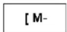
The relay is energized if the elements to which it is connected are conducting. Otherwise it is not energized.
Impulse coil:
Symbol of an auxiliary relay used as an Impulse coil:
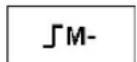
Pulse energization, the coil changes state on each rising edge it receives.
Set coil:
Symbol of an auxiliary relay used as a Set coil:
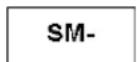
The SET coil is energized as soon as the elements to which it is connected are conducting, then stays energized even if afterward the elements are no longer conducting.
Reset coil:
Symbol of an auxiliary relay used as a Reset coil:
RM-
The RESET coil is deactivated when the elements to which it is connected are conducting. It remains deactivated even if afterward the elements are no longer conducting.
NOTE: For upward compatibility for programs operating with Zelio 1, the four types of a given output coil (Q) or auxiliary relay (M) can be used in the same wiring sheet in Zelio 2.
Use as a Contact
Auxiliary relays can be used as contacts as many times as necessary.
This contact may use the direct state of the relay (normally open contact) or its inverse state (normally closed contact), see below.
Normally open:
Symbol of an auxiliary relay used as a contact in normally open:
M-
If the relay is energized, the contact is conducting.
Normally closed:
Symbol of an auxiliary relay used as a contact in normally closed:
m-
If the relay is energized, the contact is non-conducting.
Example
In the following example turning a lamp on and off is conditioned by the state of the 6 following inputs: I1, I2, I3, I4, I5, and IB.
The lamp is on when:
- Inputs I1, I4, I5, and IB are set to 1, and
- Inputs I2 and I3 are set to 0
As the smart relay does not allow more than five contacts on a line, auxiliary relays are used to control the lamp.
We have chosen to latch inputs I1, I4, I5, and IB using auxiliary relay M1 and to latch inputs I2 and I3 using auxiliary relay M2. The lamp is controlled by relays M1 and M2, which are used as a normally open contact and a normally closed contact respectively.
Illustration:
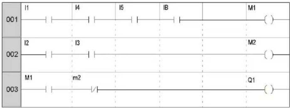
flowchart
graph LR
    A["001"] --> B["I1"]
    B --> C["I4"]
    C --> D["I5"]
    D --> E["IB"]
    E --> F["M1"]
    G["002"] --> H["I2"]
    H --> I["I3"]
    I --> J["..."]
    J --> K["M2"]
    L["003"] --> M["M1"]
    M --> N["m2"]
    N --> O["..."]
    O --> P["Q1"]
    style A fill:#f9f,stroke:#333
    style G fill:#f9f,stroke:#333
    style L fill:#f9f,stroke:#333
Modifying the State of a Coil or a Contact
To modify the type of a coil or a contact from the front panel of the smart relay (with the programming window displayed on screen):
- Position the cursor on the symbol representing the coil type or on the letter of the contact.
- Scroll through the possible coil or contact types (M for a normally open contact, m for a normally closed contact).
For more details, refer to Method for Entering a Contact or Coil (see page 47).
Initialization
State of contacts on program initialization:
- Normally open (direct state) is inactive.
- Normally closed (reverse state) is active.
Latching
By default, after a power outage, the relay is in the state that corresponds to program initialization.
To restore the state of the output as backed up before the power outage, latching must be activated:
- From the front panel: From the PARAMETERS (see page 55) menu, or
- In the programming software: Enable the Latching option in the parameters window associated with the relay.
Discrete Outputs
Description
Discrete Outputs correspond to the smart relay outputs (connected to the actuators). These outputs are numbered from Q1 to Q9, then from QA to QG, according to the smart relay reference and the connected extensions.
Discrete outputs can be used either with a coil (write) or a contact (read) element.
Use as a Coil
To use a Discrete output as a coil, four types are available:
- Direct coil
- Impulse coil
- Set (latch) coil
- Reset (Unlatch) coil
Direct coil:
Symbol of a Discrete output, used as a Direct coil:
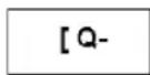
The coil is energized if the elements to which it is connected are conducting. Otherwise it is not energized.
Impulse coil:
Symbol of a Discrete output, used as an Impulse coil:
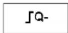
Pulse energization, the coil changes state on the rising edge of each pulse it receives.
Example: Switching a lamp on and off with a pushbutton:
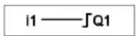
A push button is connected to input I1 and a lamp to output Q1. Every time the button is pressed, the lamp switches on or off.
Set coil:
Symbol of a Discrete output, used as a Set coil:
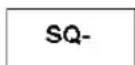
The Set coil is energized as soon as the elements to which it is connected are conducting, then stays energized even if afterward the elements are no longer conducting.
Reset coil:
Symbol of a Discrete output, used as a Reset coil:
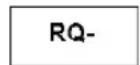
The RESET coil is deactivated when the elements to which it is connected are conducting. It remains inactive even if afterward the elements are no longer conducting.
Example: Switching a lamp on and off with two pushbuttons:
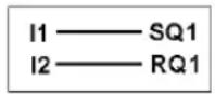
In this example, push button 1 (PB1) is connected to input I1. PBI2 to input I2. The lamp is controlled by output Q1. The lamp illuminates when pushbutton PBI1 is pressed, and it turns off when pushbutton PBI2 is pressed.
NOTE:
- Generally, an output is only used at one single point in the program as a coil (given the exception of the Set and Reset coils).
- If a SET coil is used for a Discrete output, provide a RESET coil for this output. The RESET coil takes priority over the SET coil.
The use of a Set coil on its own is only justified for activating an alarm signal that can be reset only by an INIT + ON action from the program.
Use as a Contact
An output can be used as a contact as many times as necessary.
This contact may use the direct state of the output (normally open contact) or its inverse state (normally closed contact), see below.
Normally open:
Symbol of a Discrete output, used as a contact in normally open:
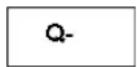
If the output is energized, the contact is conducting.
Normally closed:
Symbol of a Discrete output, used as a contact in normally closed:
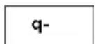
If the output is energized, the contact is non-conducting.
Modifying the State of a Coil or a Contact
To modify the type of a coil or a contact from the front panel of the smart relay (the programming window displayed on screen):
- Position the cursor on the symbol representing the coil output and press Shift key,
- Scroll through the possible coil or contact types (Q for a normally open contact, q for a normally closed contact).
For more details, refer to Method for Entering a Contact or Coil (see page 47).
Initialization
Status of contacts on program initialization:
- Normally open (direct state) is inactive,
- Normally closed (reverse state) is active.
Latching
By default, after a power outage, the outputs are in the state that corresponds to program initialization.
Activate latching to restore the state of the output as backed up before the power outage:
- From the front panel: from the PARAMETERS menu (see page 55), or
- In the programming software: Enable the Latching option in the parameters window associated with the output.
Timers
Description
Use the Timers function to delay, prolong and control actions over a predetermined period. Durations can be set using one or two preset values, according to the type of timer.
There are 11 types of timers:
• A: Active, control held down,
• a: Active, Press to start/stop,
C: Off delay,
- B: On pulse one shot: Pulse calibrated on the command input rising edge,
- W: Timing after pulse: Pulse calibrated on the command input falling edge,
• D: Symmetrical flashing: control held down synchronously,
- PD: Symmetrical flashing, Start/stop on pulse,
• T: Time on addition,
- AC: A/C: Combination of A and C,
- L: Flasher unit, control held down asynchronously,
- I: Flasher unit; Press to start/stop.
For the description of different types of timers, refer to the Timing Diagrams (see page 105).
The smart relay has either 28 timer function blocks, or 16 timer function blocks if an SR2COM01 communication interface is present. They are numbered from 1...9 then from A...V (I, M, O are not used).
NOTE: The maximum number of timers also depends on the firmware version (see page 186).
Each block has a reset input, a command input and an output used to indicate timer time-out.
Use of Coils
Two coils are associated with each timer:
- Coil TT: Command Input,
- Coil RC: Reset Input,
The use of these coils is described below.
Command input:
Symbol of the Command input coil of a timer:
TT-
Each type involves a specific operation, which can be used to manage the possible scenarios in an application.
Reset input:
Symbol of the Reset input coil of a timer:
RT-
Energization of the coil causes a reset of the timer value: contact T is deactivated and the function is ready for a new timer cycle.
NOTE: This coil is only necessary for pulse start/stop type timers.
Use as a Contact
The contact associated with the timer indicates whether the timer has stopped.
It may be used as many times as necessary in the program either as normally open or as normally closed:
Normally open:
Symbol of the normally open contact associated with a timer:
T-
If the output of the Timer function block is active, the contact is conducting.
Normally closed:
Symbol of the normally closed contact associated with a timer:
t-
If the output of the Timer function block is active, the contact is non-conducting.
Configuration from Front Panel
The block parameter settings can be accessed either when entering the command line or from the PARAMETERS menu if the block has not been padlocked.
The parameters to enter are the following:
- Timer type,
- Preset value(s),
- Time unit,
- Parameter lock,
- Latching.
Type of timer:
This parameter allows you to choose the type of timer function from among the 11 types available. Each type is represented by one or two letters:
• A: Active, control held down,
• a: Active, Press to start/stop,
C: Off delay,
- B: On pulse one shot: Pulse calibrated on the command input rising edge,
- W: Timing after pulse: Pulse calibrated on the command input falling edge,
- D: Symmetrical flashing: control held down synchronously,
- PD: Symmetrical flashing, Start/stop on pulse,
• T: Time on addition,
- AC: A/C: Combination of A and C,
- L: Flasher unit, control held down asynchronously,
- I: Flasher unit; Press to start/stop.
Preset value:
Depending on the type of timer, there can be 1 or 2 preset values:
- 1 preset value for the A, a, C, B, W, D, PD and T types:
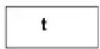
: on-delay or off-delay according to type.
- 2 preset values for the AC, L and I types:
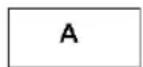
: Timer on-delay in the case of AC type; active state in the case of flasher units L
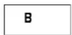
: Timer off-delay in the case of AC type; inactive state in the case of flasher units L
Time unit:
This is the time unit for the preset value. There are five possibilities:
| Unit Symbol Form Maximum value | |||
| 1/100 of a second 00.00 s 00.00 ss | |||
| 1/10 of a second 000.0 s 00.00 s S | |||
| Minutes : Seconds | M : S | 00 : 00 | 99 : 99 |
| Hour : Minute | H : M | 00 : 00 | 99 : 99 |
| Hours Only for type T. | H | 0 000 h 9,999 h | |
Parameter lock:
Symbol of the Parameter Lock parameter:

Locked

Unlocked
Locking prevents the modification of locked parameters from the front panel of the smart relay via the PARAMETERS menu.
Latching:
By default, if a power outage occurs while a timer function block is running, the information on time already elapsed is lost. When the supply voltage returns, the time function block is reinitialized and ready for a new operating cycle.
If the application requires it, the time elapsed before the power outage can be memorized using the Latching parameter.
Symbol of the Latching parameter:

Active

Inactive
This function is used to save the timer values and memorize the elapsed time in the event of a power outage.
Illustration: Configuring a counter from the front panel of the smart relay:
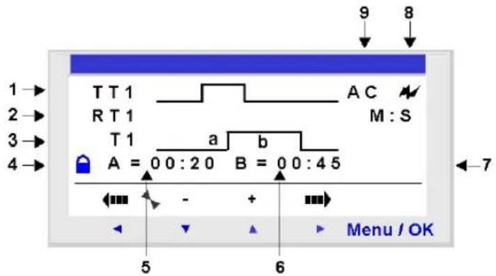
Description:
| Number | Parameter Description | |
| 1 | Command input Command input timing diagram. | |
| 2 | Reset input Reset input timing diagram. | |
| 3 | Timer output Timer output timing diagram. | |
| 4 | Parameter lock | This parameter is used to lock the counter parameters. When the block is locked, the preset value no longer appears in the PARAMETERS menu. |
| 5 | Timer on-delay Timer on-delay of the AC timer. | |
| 6 | Timer off-delay Timer off-delay of the AC timer. | |
| 7 | Time unit Time unit for the preset value. | |
| 8 | Latching Backup of counter value. | |
| 9 | Timer type Type of timer used. | |
Timing Diagrams
Timing diagrams are provided here to illustrate the various behaviors of the Timer function block, according to the selected type of timer:
Type A is Active, control held down. The following diagram shows the operation of the type A timer:
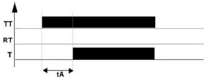
Type a is Active, Press to start/stop. The following diagram shows the operation of the type a timer:
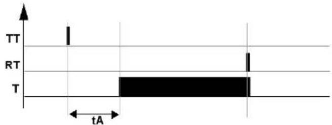
other
| Time | Signal | |------|--------| | 0 | TT | | 1 | TT | | 2 | RT | | 3 | T | | 4 | T |NOTE: Each rising edge on the TTx input resets the timer value to 0.
Type C is Off delay. The following diagram shows the operation of the type C timer:
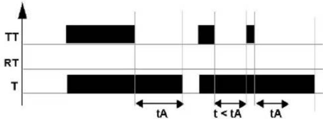
Type B is On pulse one shot for a pulse calibrated on the command input rising edge. The following diagram shows the operation of the type B timer:
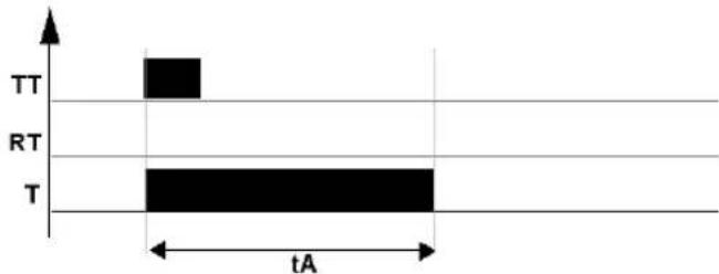
bar
| Time | Value | |------|-------| | TT | 1 | | RT | 0 | | T | 2 |Type W is Timing after pulse for a pulse calibrated on the command input falling edge. The following diagram shows the operation of the type W timer:
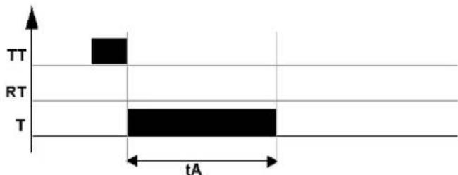
other
| Time | Signal | |------|--------| | 0 | TT | | 1 | RT | | 2 | T |Type D is Symmetrical flashing for control held down synchronously. The following diagram shows the operation of the type D timer:
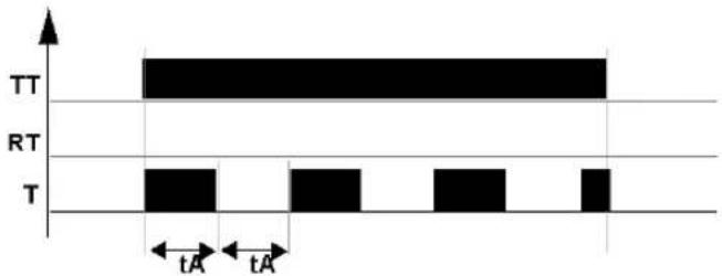
Type PD is Symmetrical flashing, Start/stop on pulse. The following diagram shows the operation of the type PD timer:
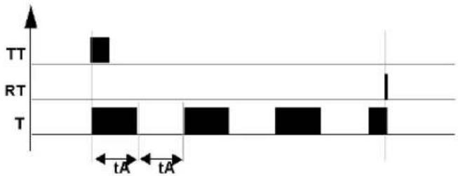
NOTE: Each rising edge on the TTx input resets the timer value to 0.
T is Time on addition. The following diagram shows the operation of the type T timer:
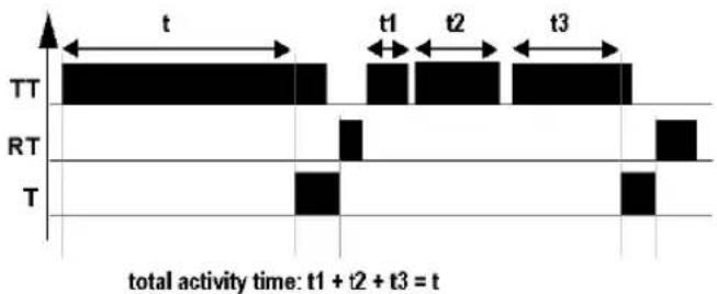
With this type, the preset value can be reached:
- In one step: t,
- In several steps: t1 + t2 + + tn .
Type AC (A/C) is a combination of A and C. The following diagram shows the operation of the type AC timer:
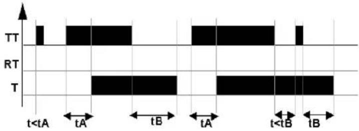
Modifying the State of a Coil or a Contact
To modify the type of a coil or a contact from the front panel of the smart relay (the programming window displayed on screen): \- Position the cursor on the symbol representing the coil type or on the letter of the contact, - Scroll through the possible coil or contact types (T for a normally open contact, t for a normally closed contact). For more details, refer to Method for Entering a Contact or Coil (see page 47).Initialization
State of the contacts and values on initialization of the program: - The normally open (direct state) is inactive, - the normally closed (inverse state) is active, - the value(s) is (are) zero(s).Example 1
Creating a timer device for a stairway. The stairway light should remain on for two minutes and thirty seconds when one of the push buttons is activated. On each floor, the buttons are linked to the I1 input of the smart relay. The stairway light is linked to the Q4 output of the smart relay. You would write the following program:  To obtain the desired operation, you should use a type B timer (On pulse one shot), and configure the duration of the timer for 2 minutes 30 seconds. To thus configure the timer duration, choose the time units M : S and enter the value 02:30 for the preset value t. Illustration: Timer's configuration screen: Counters
Description
The Counters function is used to upcount or downcount pulses. The smart relay has either 28 counters, or 16 counters if an SR2COM01 communication interface has been selected in the configuration. They are numbered from 1...9 then from A...V (I, M, O are not used). NOTE: The maximum number of counters also depends on the firmware version (see page 186). The Counters function can be reset to zero or to the preset value (depending on the chosen parameter) during use. It may be used as a contact to find out whether: - The preset value has been reached (upcounting TO), - The counter has reached 0 (downcounting FROM).Use of Coils
Each timer has 3 associated coils: - Coil CC: Counting Pulse Input, - Coil RC: Reset Initial Counter State Input, - Coil DC: Counting Direction input. The use of these coils is described below. Counting pulse input: Symbol of the Counting Pulse Input coil of a timer:  When used as a coil in a control diagram, this element represents a counting input for the function. Every time the coil is energized, the counter is incremented or decremented by 1 according to the counting direction chosen. Example: Input counting pulses delivered by counter no. 1.  Every time input I1 is energized, the counter no. 1 is incremented by 1. Reset Initial Counter State input: Symbol of the Reset Initial Counter State Input coil:  When used as a coil in a control diagram, this element represents an input that resets the counting function to its initial state. Energizing the coil has the following effect: - Reset the count value to zero if the count type is TO (upcounting to the preset value), - Reset the value to the preset value if the count type is FROM (downcounting from the preset value). Example: Counter no. 1 reset to zero by pressing Z1 key.  Every time key Z1 is pressed, the counter starts from 0. Counting direction input: Symbol of the Counting Direction Input coil of a timer:  This input determines the counting direction according to its status: - It downcounts if the coil is energized, - It upcounts if the coil is not energized. NOTE: By default, if this input is not wired, the function upcounts. Example: Up/downcounts, depending on the status of smart relay input I2.  If the I2 input is active, the function downcounts.Use as a Contact
The contact associated with the counter indicates whether the preset value (TO) or zero (FROM) has been reached. It may be used as many times as necessary in the program either as normally open or as normally closed: Normally open: Symbol of the normally open contact associated with a counter:  The contact is conducting when: - The counter value has reached the preset value, if the counter is upcounting (TO). - The counter value is equal to 0, if the counter is downcounting (FROM).Normally closed:
Symbol of the normally closed contact associated with a counter:  The contact is conducting as long as: - The counter value has not reached the preset value, if the counter is upcounting (TO). - The counter value is not equal to 0 if the counter is downcounting (FROM). Example: Lighting a LED connected to counter no. 1 output (TO).  When the preset value has been reached: The LED is illuminated; otherwise it is off.Configuration from Front Panel
The block parameter settings can be accessed either when entering the command line or from the PARAMETERS menu if the block has not been padlocked. The parameters to enter are the following: - Type of counting, - Preset value, - Parameter lock, - Latching.Type of counting:
Symbol of the type of counting parameter:  This parameter is used to select the type of the counter: • TO: upcounting towards the preset value. When the counter value is equal to the preset value, contact C of the counter is conducting. - FROM: downcounting from the preset value. When the counter value equals 0, counter contact C is conducting.Preset value:
Symbol of the preset value parameter:  This value is between 0 and 32,767, and represents: - The value to reach when counting to the preset value (TO), - The initial value when downcounting from the preset value (FROM).Parameter lock:
Symbol of the Parameter lock parameter:  Locked  Unlocked Locking prevents the modification of locked parameters from the front panel of the smart relay via the PARAMETERS menu.Latching:
Symbol of the Latching parameter:  Active  Inactive This function is used to save the status of the counter values in the event of a power outage. Illustration: Configuring a counter from the front panel of the smart relay:  Description:| Number | Parameter Description | |
| 1 | Command input Control input timing diagram (following pulse). | |
| 2 | Reset input Counter reset input timing diagram. | |
| 3 | Counter output Counter output timing diagram. | |
| 4 | Parameter lock This parameter is used [8x5W] | to lock the counter parameters. When the block is locked, the preset value no longer appears in the PARAMETERS menu. |
| 5 | Type of counting TO: upcounting towards | ds the preset value or, FROM: downcounting from the preset value. |
| 6 | Preset value Counter preset value. | |
| 7 | Latching Backup of the counter value. | |
Counter Value
The counter value is the value at a given time resulting from the successive up/down counting actions that have occurred since the last time the counter was reset to its initial state. This value is between 0 and 32767. Once these limits have been reached, a downcount will leave the value 0 and an upcount will leave the value at +32767.Timing Diagrams
In the timing diagrams, the blue curves represent the value of the counter: The following figure shows the operation of the counter when upcounting (TO) toward the preset value: line
| Time Segment | Value | | ------------ | --------- | | Initialization | R | | Counting direction | D | | Current counter value | Low | | High Saturation | +32767 | | Low Saturation | +32767 | | Output | C |bar_line
| Initialization: R | Counting direction: D | Current counter value | Preset value | Output: C | | ----------------- | --------------------- | --------------------- | ------------ | --------- | | High saturation | 0 | +32767 | 0 | 0 | | Low saturation | 0 | +32767 | 0 | 0 |Modifying the State of a Coil or a Contact
To modify the type of a coil or a contact from the front panel of the smart relay (the programming window displayed on screen): - Position the cursor on the symbol representing the coil type or on the letter of the contact, - Scroll through the possible coil or contact types (C for a normally open contact, c for a normally closed contact). For more details, refer to Method for Entering a Contact or Coil (see page 47).Initialization
Status of the contacts and value on initialization of the program: - The normally open (direct state) is inactive, - The normally closed (inverse state) is active, - The value is zero.Examples
Below, three examples of the use of a counter:| Screen Description | |
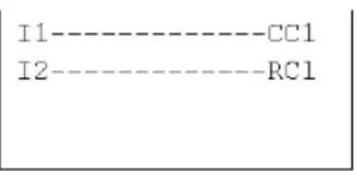 | Upcounting and zero resetting:The counter is incremented each time input I1 is activated.The counter is reset each time input I2 is activated. |
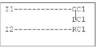 | Downcounting and Resetting:The counter is decremented each time input I1 is activated.The counter is reset each time the I2 input is activated. |
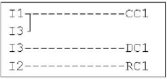 | Upcounting, Downcounting and Resetting:The counter is incremented each time input I1 is activated.The counter is decremented each time the I3 input is activated.The counter is reset each time the input I2 is activated. |
Fast Counter
Description
The Fast Counter function is used to count pulses up to a frequency of 1 kHz. Use of the K1 contact indicates: - The preset value has been reached (upcounting), - The value 0 has been reached (downcounting). The Fast counter inputs are implicitly connected to the I1 and I2 smart relay inputs: - A pulse (rising edge) on the I1 input increments the counter, - A pulse (rising edge) on the I2 input decrements the counter. These inputs cannot be used in any other context. The Fast Counter function can be reset to zero during use by the RK1 coil. It is reset to: - 0 if it is upcounting towards the preset value - the preset value if it is downcounting from the preset value. The counter only operates if the TK1 confirmation coil is active. Repetitive cycle type can be used with a time-delay value. NOTE: Limit overrun: - If the value of the counter exceeds the upper limit: +32,767, it is set to -32,768, - if the value of the counter exceeds the lower limit: -32,768, it is set to +32,767. NOTE: This function block cannot be simulated.Use of Coils
Two coils are associated with the fast counter: • coil TK1: Enable function input, - coil RK1: Reset initial counter state input. The use of these coils is described below. Enable function input: Symbol of the Enable Function Input coil of the fast counter: TK1 This element is used to confirm the counter. When this coil is active, each rising edge on the I1 input will increment the Fast counter and each rising edge on the I2 input will decrement it. Reset initial counter state input: Symbol of the Reset Initial Counter State Input: RK1 This input resets the counter function to its initial state. Energizing the coil has the following effect: \- reset the counter value to zero if the count type is TO (upcounting to the preset value). \- reset the counter value to the preset value if the count type is FROM (downcounting from the preset value). Example: Counter reset by pressing on the Z1 key: Z1——RK1 Each time the Z1 key is pressed, the counter is reinitialized.Use as a Contact
The contact associated with the fast counter indicates whether the preset value (TO) or zero (FROM) has been reached. It may be used as many times as necessary in the program either as normally open or as normally closed: Normally open: Symbol of the normally open contact associated with the fast counter: K1 The contact is conducting when: \- the value of the counter has reached the preset value (TO), \- the value of the counter has reached 0 (FROM). Normally closed: Symbol of the normally closed contact associated with the fast counter: k1 The contact is conducting as long as: \- the counter value has not reached the preset value, if the counter is upcounting, \- the counter value has not reached 0, if the counter is downcounting, Example: Lighting a LED connected to fast counter no. 1 output (TO).  When the preset value has been reached: The LED is illuminated; otherwise it is off.Configuration from Front Panel
The block parameter settings can be accessed either when entering the command line or from the PARAMETERS menu if the block has not been padlocked. The parameters to enter are the following: - Cycle type, • Duration of pulse, - Preset value, - Type of counting, - Parameter lock, - Latching.Cycle type:
This parameter determines the behavior of the fast counter when it reaches the preset value (when upcounting TO), or when it reaches the value zero (when downcounting FROM): The cycle type may be: - Single: Reaching the preset value (when upcounting TO) or the zero value (when downcounting FROM) does not affect the value of the counter. The counter value changes on an on-going basis. The output is activated when the value is greater than the preset value (when upcounting TO) or when it is less than the preset value (when downcounting FROM). - Repetitive: when upcounting TO, the value is reinitialized when it reaches the preset value and when downcounting FROM, it is reset to the preset value when it reaches zero. The output is enabled following this reinitialization and remains active for a time that may be configured with the parameter: Duration of pulse (from 1 to 32,767 times 100 ms).Duration of pulse:
Symbol of the Duration of pulse parameter:  This parameter is only displayed if the cycle is repetitive. It determines the duration during which the fast counter remains active when the value reaches the preset value (when upcounting TO), or when it reaches the value zero (when downcounting FROM). This value must be between 1 and 32,767 (x 100 ms). Preset value: Symbol of the Preset value parameter:  This value is between 0 and 32,767, and represents: - the value to reach when upcounting to the preset value (TO), - the initial value when downcounting from the preset value (FROM). Type of counting: Symbol of the Type of counting parameter:  This parameter is used to select the type of the counter: • TO: upcounting towards the preset value. When the counter value is greater than or equal to the preset value, contact K1 of the fast counter is conducting. - FROM: downcounting from the preset value. When the counter value is less than or equal to 0, contact C of the counter is conducting. Parameter lock: Symbol of the Parameter Lock parameter:  Locked  Unlocked Locking prevents the modification of locked parameters from the front panel of the smart relay via the PARAMETERS menu. Latching: Symbol of the Latching parameter:  Active  Inactive This function is used to save the status of the fast counter values in the event of a power outage. Illustration: configuring a counter from the front panel of the smart relay:  Description:| Number | Parameter Description | |
| 1 | Cycle type Single/Repetitive | |
| 2 | Duration of pulse Only if the cycle is repetitive | |
| 3 | Parameter lock This parameter is used to lock the counter parameters. When the block is locked, the preset value no longer appears in the PARAMETERS menu.  | |
| 4 | Type of counting Counter configuration: Counting to the preset value (TO) or from the preset value (FROM). | |
| 5 | Preset value Counter preset value. | |
| 6 | Latching Backup of the counter value. |
Counter Value
Value at a given instant resulting from successive up/down counts since the last counter reset to its initial state. If the value of the counter exceeds the upper limit: +32,767, it is set to -32,768. If the value of the counter exceeds the lower limit: -32,768, it is set to +32,767.Timing Diagrams
Timing diagrams are provided here to illustrate the various behaviors of the fast counter according to its parameters: - upcounting function TO, in single cycle type, - downcounting function FROM, in single cycle type, - upcounting function TO, in repetitive cycle type, - downcounting function FROM, in repetitive cycle type. For the following 4 charts, the blue curve represents the value of the counter. When it increases, it is because of pulses on I1 and when it decreases, it is because of pulses on I2. UpCounting in Single Cycle Type: The figure below illustrates the counter function in upcounting and single cycle type: bar_line
| Signal Type | Value | | ----------------- | --------- | | Confirmation | High | | Initialization | Low | | CURRENT_COUNTER_VALUE | +32767 | | Current_COUNTER_VALUE | -32767 |Modifying the State of a Coil or a Contact
To modify the type of a coil or a contact from the front panel of the smart relay (the programming window displayed on screen): - Position the cursor on the symbol representing the coil type or on the letter of the contact, - Scroll through the possible coil or contact types (K for a normally open contact, k for a normally closed contact). For more details, refer to Method for Entering a Contact or Coil (see page 47).Initialization
Status of the contacts and value on initialization of the program: - The normally open (direct state) is inactive, - the normally closed (inverse state) is active, - The value is zero.Example
Below, an example of using a fast counter: output Q1 is set to 1 when the fast counter is set to 1; the counter is activated by input I3 and reset to 0 by input I4. Counter Comparators
Description
This function is used to compare the values of two counters or of a counter and a constant value. NOTE: The Counter Comparators function block can only be configured from the programming software in Ladder Entry. See on-line help of the programming software for more information.Use as a Contact
The counter comparator indicates whether the chosen condition is verified. It is used as a contact, in normally open or in normally closed. Normally open: Symbol of the counter comparator, in normally open: V1 The contact is conducting when the condition is verified. Normally closed: Symbol of the counter comparator, in normally closed: v1 The contact is conducting when the condition is not verified.Configuration from the Front Panel
The Counter Comparators function block cannot be configured from the front panel of the smart relay. This function must be configured from the programming software. See on-line help of the programming software for more information on configuration.Modifying the State of a Coil or a Contact
To modify the type of a coil or a contact from the front panel of the smart relay (the programming window displayed on screen): - Position the cursor on the symbol representing the coil type or on the letter of the contact, - Scroll through the possible coil or contact types (V for a normally open contact, v for a normally closed contact). For more details, refer to Method for Entering a Contact or Coil (see page 47).Initialization
Status of contacts on program initialization: - Normally open (direct state) is inactive, - Normally closed (reverse state) is active.Analog Comparators
Description
The Analog Comparators function block is used to: - Compare a measured analog value with a reference value. - Compare two measured analog values. - Compare two measured analog values with hysteresis parameter. The result of this comparison is used in the form of a contact. Analog automation functions can be used for smart relays with a real time clock and DC power supply, and with mixed discrete and analog inputs. The following indicate the existence of mixed discrete and analog inputs: - The existence of inputs numbered from IB to IG (maximum configuration). These inputs are used to receive analog signals from 0.0 V to 9.9 V inclusively. - The presence of the Analog Comparators function in the toolbar of the programming software. These smart relays have 16 Analog Comparators function blocks, numbered from 1 to 9 then from A to G.Use as a Contact
The contact shows the position of a measured analog value in relation to a reference value or to another measured value. It may be used as many times as necessary in the program either as normally open or as normally closed: Normally open: Symbol of the normally open contact associated with an Analog Comparator:  The contact is conducting when the comparison condition is verified. Normally closed: Symbol of the normally closed contact associated with an analog comparator:  The contact is conducting when the condition is not verified.Configuration from Front Panel
The comparison formula is as follows:xl <Comparison Operator > x2
x1 - H ≤ x2 ≤ x1 + H
| Number Comparison formula | |
| 1 | x |
| 2 | x |
| 3 | x |
| 4 | x |
| 5 | x |
| 6 | x |
| 7 | comparison with hysteresis: x1 - H ≤ x2 ≤ x1 - H |
| Number | Parameter Description | |
| 1 Type of comparison The number that follows ANALOGcorresponds to the selected comparison operator. | ||
| 2 Comparison formula Formula used for comparison. | ||
3 Parameter lock Locking prevents locked parameters from being modified from the front panel of the smart relay using the PARAMETERS menu. being modified from the front panel of the smart relay using the PARAMETERS menu. | ||
| 4 Parameters of the comparison formula | Parameters of the comparison formula. | |
Modifying the State of a Coil or a Contact
To modify a contact from the front panel of the smart relay (the programming window is displayed on the screen): - Place the cursor over the letter of the contact, - Scroll through the possible contact types (A for a normally open contact, a for a normally closed contact). For more details, refer to Method for Entering a Contact or Coil (see page 47).Initialization
Status of the contacts and value on initialization of the program: - The normally open (direct state) is inactive, - The normally closed (inverse state) is active.Example
A heating resistance is to be triggered by the smart relay Q1 output when the temperature is below 20^ C. A temperature probe is used, providing a 0 to 10 volt signal for a -10^ to +40^ C temperature range. A temperature of 20^ C corresponds to a voltage level of 6 volts on the probe. You would write the following Ladder program:  Using the following parameters for the A1 comparator:  The comparison operator 5 is chosen, that is “inferior or equal to”. The values to compare are chosen: The analog input IB (to which the temperature probe is connected) for the first, the reference value R for the second. The reference value is set to 6. The analog comparator is thus active when the power measured on the analog input IB is less than or equal to 6 V. This is when the probe measures a temperature less than or equal to 20 °C.Clocks
Description
Use the Clocks function to validate the time ranges during which actions can be executed. The smart relay has 8 Clocks function blocks numbered from 1...8. Each of these has four programming ranges and behaves like a weekly programmer. The Clocks function blocks are used like contacts.Use as a Contact
This contact may use the direct state of the Clock function block (normally open contact) or its inverse state (normally closed contact), see below. Normally open: Symbol of the normally open contact, representing a clock:   The contact is conducting when the clock is in a validity period. Normally closed: Symbol of the normally closed contact, representing a clock:   The contact is conducting when the clock is not in a validity period.Configuration from Front Panel
Configuration screen of a Clock function block from the front panel of the smart relay: | Number | Parameter Description | |
| 1 | Clock module number 8 clocks available, numbered 1...8. | |
| 2 | Type of date configuration D/W: Days of the Week. | |
| 3 | Validity day (D/W type) Validity day: | 0: Monday1: Tuesday...6: SundayUnselected days are indicated by a _. |
| 4 | Start time (D/W type) | This is the start time from 00.00...23:59. |
| 5 | Stop time (D/W type) This is the end time from 00.00...23:59. | |
| 6 | Parameter lock Locking prevents locked parameters from  being modified from the front panel of the smart relay using the PARAMETERS menu. being modified from the front panel of the smart relay using the PARAMETERS menu. | |
| 7 | Operating ranges 4 operating ranges are available: A, B, C, D.In operation, these ranges are cumulative: The block is valid over the selected ranges. | |
Combining Operating Ranges
Operating ranges can be mixed for the same clock. Example: Using the four operating ranges with different settings.| Operating range Program | |
| A: time range | Every day from Monday to Friday, start at 8.00 and end at 18.00. |
| B: Day/Night | Every day from Tuesday to Thursday: start at 22.00 and end the following day at 6.00. |
| C: interval | Start on Friday at 20.00. |
| D: Interval | End on Monday at 03.00. |
Modifying the State of a Coil or a Contact
To modify the type of a coil or a contact from the front panel of the smart relay (the programming window displayed on screen): - Place the cursor over the letter of the contact, - Scroll through the possible contact types (H for a normally open contact, h for a normally closed contact). For more details, refer to Method for Entering a Contact or Coil (see page 47).Example
You wish to control a device connected to the Q2 output of the smart relay. You want it to be active on the following two clock ranges: • from Monday to Saturday, from 09:00 to 13:00. • from Monday to Friday, from 15:00 to 19:00. For this, the H1 Clock block is used and the following wiring sheet is created: H1----[Q2 When entering the H1, Clock block, configure the operational ranges A and B as described in the table below: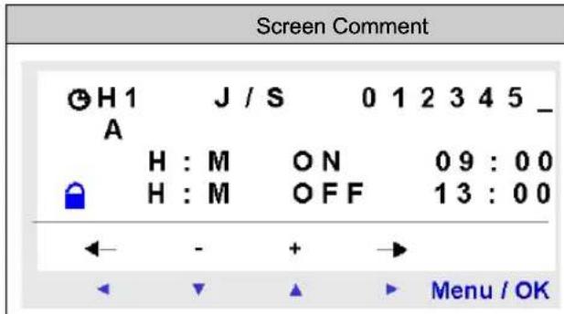 | First Slot A: From Monday to Saturday, from 09:00 to 13:00. |
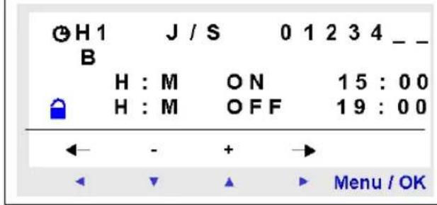 | Second Slot B: From Monday to Friday, from 15:00 to 19:00. |
TEXT
Description
The TEXT function is used to display text, a date, a time, and numerical values on the LCD display, instead of the inputs-outputs states. One single TEXT function block is used to define the content of the entire LCD display. The content can be a combination of: • Text (maximum 72 characters), - Numerical values corresponding to the output of a function used in the application (for example a counter). These values can include a decimal point. - Date, time or calibration value from the Clocks function. It is possible to authorize the modification of the content using the keys on the front panel. The smart relays have 16 TEXT blocks, numbered from 1...9 then from A to G. These function blocks are used as coils. The maximum number of variables that can be displayed per TEXT block is 4. Up to 16 TEXT blocks may be used (TX1 to TXG) simultaneously in one program, but only the block which is activated is displayed. If multiple blocks are activated, the block with the highest number is displayed. To switch the display from the TEXT screen to the INPUTS-OUTPUTS screen, hold down the Shift key, then press the Menu/OK key. NOTE: The TEXT blocks are only programmable from the programming software.Used as a Coil
Two coils are associated with each TEXT block: - Display Activation coil. - Display Deactivation coil. The use of these coils is described below. Display Activation Symbol of the Display Activation coil of a TEXT function block: TX - This coil displays on the screen the text and/or the values of the associated TEXT block when the elements that are connected are conducting. Display Deactivation Symbol of the Display Deactivation coil of a TEXT function block: RX - This coil deactivates the display of the text and/or the values of the associated TEXT block when the elements that are connected are conducting. The display returns to the inputs-outputs screen. Example:  Activation of input I1 displays the text on the LCD. Activating input I2 makes the text disappear.Parameter
The TEXT function blocks are only programmable from the programming software, see the on-line help for the programming software for more information.LCD Screen Backlighting
Description
The LCD screen backlighting output is used to control the backlighting of the LCD by a program. In STOP and RUN modes, the LCD screen is illuminated for 30 seconds when a key is pressed on the front panel.Used as a Coil
Used as a coil, it illuminates the LCD when the elements to which it is connected are conducting. Symbol of the coil of the LCD screen Backlighting function: TL1 The screen is illuminated if this coil is active.Change to Summer / Winter Time
Description
The output of this function is in an OFF state over the entire duration of winter time, and switches to ON for the entire duration of summer time. By default, there is no change in winter / summer time. This function must be activated, either from the programming software, or from the front panel of the smart relay. To activate this function from the front panel of the smart relay, proceed as described in chapter CHANGE SUM/WIN Menu (see page 85). NOTE: This function is only available for smart modules that contain a real-time clock.Use as a Contact
When used as a contact, this element indicates winter time or summer time. It may be used as many times as necessary in the program either as normally open or as normally closed: Normally open: Symbol of the normally open contact associated with a Change summer / winter time function block: W1 The contact is active for the entire duration of summer time. Normally closed: Symbol of the normally closed contact associated with a Change summer/winter time function block w 1 The contact is active for the entire duration of winter time.Parameters
The following settings are possible: - No: no change, - Automatic change: Dates are preset according to geographic zone: - EUROPE: Europe, USA. \- OTHER ZONE: The change is automatic, but you must specify the month: M and the Sunday: S (1, 2, 3, 4 or 5) on which the summer/winter change takes place.Modifying the State of a Coil or a Contact
To modify a contact from the front panel of the smart relay (the programming window displayed on screen): - Place the cursor over the letter of the contact, - Scroll through the possible contact types (W for a normally open contact, w for a normally closed contact). For more details, refer to Method for Entering a Contact or Coil (see page 47).Initialization
State of the contacts and value on initialization of the program: - The normally open (direct state) is inactive, - The normally closed (inverse state) is active.Modbus Inputs/Outputs
Description
A Modbus SR3MBU01BD extension module may be added onto an extensible smart relay. In LD mode, the application cannot access the four 16-bit data exchange words. Data transfer between master and slave is implicit and transparent. NOTE: The Modbus module only operates as Modbus slave.Parameters
The Modbus module can be configured only from the programming software (see the on-line help of the programming software for more information).Words to be sent to master
Writing these words to the master is automatically performed by duplication of the status of the discrete I/Os as follows:  I1 to IG: discrete input states for the SR3B261BD base. IH to IR: discrete input states for the SR3XT141BD extension. Q1 to QA: discrete output states for the SR3B261BD base. QB to QG: discrete output states for the SR3XT141BD extension.Words sent by the master
The words sent by the master are not implicitly operated on by the smart relay. These 4 16-bit words have the following addresses (Hexa): 0x0010 / 0x0011 / 0x0012 / 0x0013.Message
Description
When activated, the Message function block can be used to: - Send alarm messages to mobile phones, the Zelio Logic Alarm tool or Email addresses via the SR2COM01 communication interface - Provide remote access to I/O and/or a digital variable for reading or modifying them. There are 28 Message function blocks numbered from S1...S9, then from SA...SV (SI, SM, SO are not used). NOTE: The Message function is only available on smart relays with clocks and when an SR2COM01 communication interface is added. For further information on the configuration of the SR2COM01 communication interface, see the programming software on-line help.Use of the Coil
Command input Symbol of the Command Input coil of a Message function block: TS- This coil sends the configured alarm message in the associated Message function block, when it is activated. Depending on the configuration of the Message function block, the coil may be activated during detection on its input, by a transition: \- From Inactive to Active State (by default), \- From Active to Inactive State. See on-line help for the programming software for more information on configuring the Message function block.Use as a Contact
The contact associated with the Message function block indicates whether the function block is activated. It may be used as many times as necessary in the program either as normally open or as normally closed: Normally open: Symbol of the normally open contact associated with a Message function block: S- The contact is conducting when the function block is activated.Normally closed:
Symbol of the normally closed contact associated with a Message function block:  The contact is conducting as long as the function block is not activated. Example: Illuminating an LED connected to the Message No.1 function block output  When function block no. 1 is activated, the associated alarm message is sent and the LED is illuminated, otherwise it is off.Modifying the State of a Coil or a Contact
To modify the type of a coil or a contact from the front panel of the smart relay (the programming window displayed on screen): \- Position the cursor on the symbol representing the coil type or on the letter of the contact, - Scroll through the possible contact types (S for a normally open contact, s for a normally closed contact). For more details, refer to Method for Entering a Contact or Coil (see page 47).Configuration from the Front Panel
The Message function block cannot be configured from the front panel of the smart relay. This function must be configured from the programming software. See on-line help of the programming software for more information on configuration.Initialization
Status of contacts on program initialization: - The normally open (direct state) is inactive, - The normally closed (inverse state) is active.Part IV
Creating and Debugging an Application
Subject of this Section
This section describes, using detailed examples, how to create, debug and save an application.What Is in This Part?
This part contains the following chapters:| Chapter Chapter Name Page | ||
| 17 Implementing an Application 145 | ||
| 18 Debugging an Application 159 | ||
| 19 Transfer of Ladder Diagrams 167 | ||
| 20 Sample Application 169 | ||
Chapter 17
Implementing an Application
Subject of this Chapter This chapter describes the implementation of an application from the front panel of the smart relay. What Is in This Chapter? This chapter contains the following topics:| Topic Page | |
| Presentation of Ladder Diagrams 146 | |
| Using the Reverse Function 148 | |
| Notation Used by the Smart Relay 150 | |
| Application: Implementing a Two-way Switch 152 |
Presentation of Ladder Diagrams
Description
In this section, we will use an example to understand how a ladder diagram works for a two-way switch.| Electrical diagram Ladder diagram | |
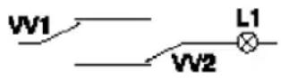 | 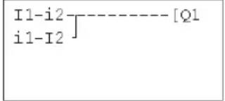 |
| The two position switches VV1 and VV2 control turning lamp L1 on and off. | I1 and I2 are two contacts representing inputs 1 and 2 on the smart relay.Q1 is a coil that corresponds to output 1 from the smart relay. |
Module Wiring
Below, an illustration of smart relay wiring: Application Operation
Using a smart relay means that ordinary switches (with open or closed positions) can be used in place of two position switches. The switches are identified as S1 and S2 in the wiring diagram above. S1 and S2 are connected to inputs I1 and I2 on the smart relay. The operating principle is as follows: Each time the status of inputs I1 and I2 changes, the status of output Q1 also changes which controls the lamp L1. The ladder diagram uses simple functions, for example placing contacts in parallel and in series, as well as the reverse function identified as i1 and i2 (see Using the Reverse Function, page 148). NOTE: The implementation of a two-way switch is optimum when impulse relay coils are used (see Discrete Outputs, page 98).Using the Reverse Function
Description
The reverse function, noted i in the smart relay is used to obtain the reverse state of input I wired on the smart relay.Practical Example
Below is the electrical diagram of the example and an illustration of the smart relay wiring:| Electrical diagram | Connection to the smart relay |
| BP1 L1⊗ L1 | Fuse 2 Fuse 1 100 ... 240 VAC 50 / 60 Hz N PB1 L N I1 I2 I3 I4 I5 I6 I7 I8 OUTPUTS Q1 ... Q4: Relay 8A 1 2 1 2 1 2 1 2 Q1 Q2 Q3 Q4 L1 |
| BP1(or PB1) pushbutton L1 LED | |
| Ladder diagram 1: Light off when idle Ladder diagram 2: Light on when idle | |
| I1----[Q] | i1----[Q] |
| I1 corresponds to the image of BP1, pressing BP1 activates input I1, so that the Q1 output is activated and the lamp L1 is illuminated. | i1 corresponds to the reverse image of BP1, pressing BP1 activates input I1 and therefore contact i1 is disabled, output Q1 is disabled and the lamp L1 is not illuminated. |
General Case
The table below illustrates the operation of a pushbutton connected to the smart relay. Pushbutton BP1 is connected to input I1 and lamp L1 is connected to output Q1 on the smart relay.| Off delay Operating | ||||
| Electrical diagram | Smart relay symbols | Electrical diagram | Smart relay symbols | |
| Pushbutton normally open | 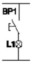 | I1 = 0i1 = 1 | 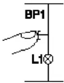 | I1 = 1i1 = 0 |
| Pushbutton normally closed | 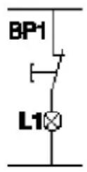 | I1 = 1i1 = 0 | 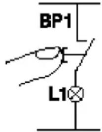 | I1 = 0i1 = 1 |
Notation Used by the Smart Relay
Description
The smart relay has a 4-line display used to show ladder diagrams. NOTE: The programming software allows you represent ladder diagrams in three different formats: • Electrical symbols - Ladder symbols - Smart relay symbolsEquivalences Between Notations
In the table below are the representations of common elements in the 3 formats:| Electrical symbol Ladder symbol Smart relay symbols | ||
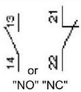 | 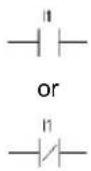 | I1 or i1I1 or i1 |
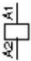 |  | [Q1] |
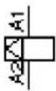 Set coil (SET) Set coil (SET) |  | SQ1 |
 Reset coil (RESET) Reset coil (RESET) |  | RQ1 |
Other Elements
Other elements are also available using a smart relay, such as: - Timer function block: Used to delay, prolong and control and action for a set length of time, - Counter function block: Used to count the pulses received on an input, - Clock function block: Used to trigger or release actions on precise days or at precise times, - Analog comparator function block: Used to compare an analog value with a reference value or with another analog value after allowing for a hysteresis factor, - Auxiliary relays: These are used to save or relay the status of the smart relay, - Zx keys: After confirming this function, Z keys may be used as pushbuttons, - Fast counter function block: The fast counter function is used to count pulses up to a frequency of 1 kHz. - LCD screen back-light function block: This is used to control the backlighting of the LCD by a program, - Summer/winter time change function block: The output of this function is in an OFF state over the entire duration of winter time, and switches to ON for the entire duration of summer time, - Counter Comparator block: This function is used to compare the values of two counters, - Text block: This is used to display text or numerical values (value or preset value). NOTE: Blocks Counter Comparator and Text are not programmable from the front panel. NOTE: For the list of the ladder diagram elements available when using smart relays, as well as details on their functions and parameters, see the chapter entitled LD Language Elements, page 89.Application: Implementing a Two-way Switch
Description
In the text that follows you will find detailed information on the procedure for entering a ladder diagram for a two-way switch. You should proceed as follows: - Go to the programming screen, - Enter the contacts in the first line, - Enter the coil in the first line and link it to the contacts, - Enter the contacts in the second line, - Link the second line to the first, - Launch the program. To read the next procedures, from the main smart relay screen (the one shown on power-up), follow the instructions written in the Action column and press the specified key. The Screen column shows what you see on the smart relay screen. The Comments column provides some additional information on entry and display actions.Go to the Programming Screen
To access the screen from which we will program the two-way switch, proceed as follows:| Step Action Smart relay screen Comment | |||
| 1 |  | PROGRAMMINGPARAMETERSRUN/STOPCONFIGURATION | Position the cursor on PROGRAMMING; it will flash when selected. |
| 2 |  | LINE 2LINE 3LINE 3 | After briefly displaying: LINE 1 (for approx. two seconds), a ■flashing cursor is displayed. |
| 3 |  | ins - + Del. | Pressing and holding down the Shift key (white) will make a contextual menu appear that is used for programming the contacts and the coils. |
Entering the Contacts in the First Line
To enter the contacts in the first line, proceed as follows:| Step Action Smart Relay Screen Comment | |||
| 1 |  | I1 | The ■flashing cursor is positioned on the I. The smart relay prompts you to select the type of contact. |
| 2 |  | I1 | The 1 flashes.You have selected a contact assigned to an input (I), the smart relay now prompts you to select the input number. |
| 3 |  | I1● | The ●flashes, indicating a link point for linking connections. |
| 4 |  | I1■ | The ■flashes.You just confirmed entry of the contact associated with the input I1. The ■is positioned for entering the second contact. |
| 5 |  | I1-I1 | The right side I will begin flashing. The smart relay prompts you to select the type of contact. |
| 6 |  | I1-i1 | The i flashes.You have just selected the reverse contact assigned to an input. |
| 7 |  | I1-i1 | The 1 on the right flashes.Now enter the input number. |
| 8 |  | I1-i2 | The 2 flashes. |
Entering the Coil and Linking it to the Contacts
To enter the coil in the first line and connect it to the coils, proceed as follows:| Step Action Smart Relay Screen Comment | |||
| 1 |  | I1-i2 ●I1-i2 ■...thenI1-i2 ■ | The cursor flashes in succession:● At a link point: ●● At a contact point: ■Until positioned at the end of the line ready to enter the coil. |
| 2 |  | I1-i2 [M1] | The [ flashes. |
| 3 | —— | I1-i2 [M1] | The M flashes. |
| 4 |  | I1-i2 [Q1] | The Q flashes. |
| 5 | —— | I1-i2 [Q1] | The cursor is displayed. |
| 6 |  |  | Pressing and holding down the Shift key (white) will make a contextual menu appear that is used for programming the connections. |
| 7 |  |  | The link is created. |
Entering the Contacts in the Second Line
To enter the contacts in the second line, proceed as follows:| Step Action Smart Relay Screen Comment | |||
| 1 |  as many times as necessary until positioned at the start of the line. as many times as necessary until positioned at the start of the line. | I1-i2----[Q1■ | The is at the start of the following line. |
| 2 |  | I1-i2----[Q1I1 | The I located on the second line flashes. |
| 3 |  | I1-i2----[Q1i1 | The i located on the second line flashes. |
| 4 | —— | I1-i2----[Q1i1 | The 1 located on the second line flashes. |
| 5 |  x2 x2 | 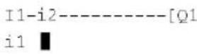 | The ■flashes. |
| 6 |  | I1-i2----[Q1i1-I1] | The I located on the second line flashes. |
| 7 |  | I1-i2----[Q1i1-I1] | The second 1 in the second line flashes. |
| 8 |  | I1-i2----[Q1i1-I2] | The 2 located on the second line flashes. |
Linking the Second Line to the First
To link the second line to the first, proceed as follows:| Step Action Smart Relay Screen Comment | |||
| 1 |  | I1-i2----[Q1i1-I2 ◆ | The ●flashes.This shows that it is possible to connect a link at this point. |
| 2 |  | I1-i2----[Q1i1-I2 ] | The ●has changed into a | which creates the link between the two lines. |
Launching the Program
To launch the program, proceed as follows:| Step Action Smart Relay Screen Comment | |||
| 1 |  | CONFIRM CHANGES ?YESNO | Now confirm the changes.YES flashes. |
| 2 |  | PROGRAMMINGPARAMETERSRUN/STOPCONFIGURATION | The main menu re-appears.PROGRAMMING is selected (flashes). |
| 3 |  | PROGRAMMINGPARAMETERSRUN/STOPCONFIGURATION | RUN/STOP is selected (flashes). |
| 4 |  | RUN PROG.WITH NONVOLAT ININO NONVOLAT ININO | Now start the program using the required option(see page 59). |
| 5 |  | 123456RUN LDTUE 03 JAN 16:061234 | The main menu re-appears. |
The Main Points
This application example illustrates how to enter a ladder diagram. - When a ■ or a ● is flashing, use the Shift key to add an element (contact, coil or graphic link element), - When an element is flashing (I, Q, No., etc.), it is possible to use the Shift + Z2 and Z3 arrows on the arrow keypad to select the required element, - It is also possible to use the Z1 to Z4 arrows on the arrow keypad to move around the ladder diagram.Chapter 18
Debugging an Application
Subject of this Chapter
This chapter presents the tools available for debugging an application loaded in the memory of the smart relay.What Is in This Chapter?
This chapter contains the following topics:| Topic Page | |
| Introduction 160 | |
| Run Mode Ladder Diagrams 162 | |
| Run Mode Function Block Parameters 163 | |
| Run Mode Menus 164 | |
| Smart Relay Reaction to a Power Outage 165 |
Introduction
Smart Relay Module in RUN Mode
Once an application has been entered in ladder diagram form, debugging tests must be run. The first step is to set the smart relay to RUN. To do this, in the RUN/STOP option in main menu and select RUN. From this moment on, the smart relay handles the physical inputs and outputs according to the instructions entered in the ladder diagram.Viewing Status:
In RUN mode, the states of inputs and outputs are displayed on the main screen: | Prompt Element |
| 1 Display input status |
| 2 Display run mode (RUN/STOP) and mode in use. |
| 3 Displays date and time for products with clocks. |
| 4 Output status display. |
| 5 Contextual menus / pushbuttons / icons indicating operating modes. |
Contextual Menus
Below is an illustration of the icons in the contextual menu when the smart relay is in RUN mode: | Prompt Element |
| 1 Status of the smart relay: In RUN it is in motion, in STOP it is immobile. |
| 2 Indicates that errors have been detected (see DEFAULT Menu, page 79). |
| 3 Indicates that the smart relay is connected to the programming software. |
| 4 The key indicates that the program is password-protected. |
Run Mode Ladder Diagrams
Viewing Ladder Diagrams
NOTE: Viewing I/O and variable values can be accessed only in LD/ RUN mode. The smart relay can dynamically display the performance of a ladder diagram. To do this, simply call up the MONITORING menu and position the cursor over the lines to display using the navigation keys. Each conducting contact or energized coil is displayed in reverse video (white on black): Modifying Ladder Diagrams
You cannot modify the ladder diagram lines in RUN mode. However, you can modify some of the function block parameters in the MONITORING menu.Using Z Keys as Pushbuttons
On the INPUTS-OUTPUTS screen in RUN mode, the numbers of the Z keys used in the program are displayed in the contextual menu. Press and hold down the Shift key to display the contextual menu. To enable a Z key, press on the key located under the number. Illustration:  NOTE: The Zx keys function is disabled in the PARAMETERS and MONITORING menus and in the function block parameter screens and configuration screens.Run Mode Function Block Parameters
Presentation
In RUN mode a function block preset value may be changed dynamically if it is not locked. Functions with parameters in LD mode: • Auxiliary relays (latching), - Clocks - Analog comparators, - Timers - Counters - Fast counters. \- Discrete Outputs (latching), Functions with parameters in FBD mode: • Numerical constant-type inputs, - Clock, - Gain, - Timers: TIMER A/C, TIMER B/H, TIMER Li, - Counter: PRESET COUNT / UP DOWN COUNT, • H-SPEED COUNT fast counter, - PRESET H-METER hour counter, - CAM block, - PID.Accessing / Modifying parameters
Parameters may be accessed from the following screens: • PARAMETERS: See PARAMETERS Menu, page 55, • MONITORING: on the ladder diagram. To modify the parameters of an element from the MONITORING menu, proceed as follows:| Step Action | |
| 1 Position the cursor on the element to modify using the navigation keys. | |
| 2 | At the same time, hold down Shift and the Param key to open the parameter window. |
| 3 Position the cursor on the modifiable parameter fields using the navigation keys: . ◀ ▶ | |
| 4 | Modify the value of the parameter using the ▲ and ▲ (+ and -) keys, holding down Shift. |
| 5 Confirm the modifications by pressing Menu/OK, which will open the confirmation window. Confirm a second time by pressing Menu/OK to save. | |
Run Mode Menus
Run Mode Menus
Some menus are accessible when the smart relay is in RUN mode, while others are not. Here is a summary table.| Menu LD FBD | |||
| PROGRAMMING | |||
| MONITORING | √ | ||
| PARAMETERS | √ | √ | |
| RUN / STOP | √ | √ | |
| CHANGE D/T | √ | √ | |
| CHANGE SUMM/WINT | √ | √ | |
| CONFIGURATION | |||
| PASSWORD | ORD | ||
| F I L T E | R | ||
| Zx KEYS | |||
| WATCHD | OG CYCLE | ||
| CLEAR PROG. | |||
| TRANSFER | |||
| VERSION | √ | √ | |
| LANGUAGE | √ | √ | |
| DEFAULT | √ | √ | |
Smart Relay Reaction to a Power Outage
Description
A power outage may cause the smart relay to restart and lose any data not declared as non-volatile. Smart relays have the ability to maintain the time for at least 10 years. In addition, it is also possible to back up the variables configured with the Latching option defined in the parameters window.Latching
The Latching function is used to save the counter values in the event of a power outage. The blocks that have this function are the following: \- In LD mode: o Auxiliary relays, ○ Discrete outputs, ○ Timers o Counters - Fast counter, \- In FBD mode: ○ AC, BH, Li timer, - Cam programmer function CAM BLOCK, o PRESET COUNT, UP DOWN COUNT counter, ○ PRESET H-METER hour counter, ○ Data archiving function ARCHIVE, - Fast counters.Locked Coil Control
If the result of losing the time setting is to lock coil control, then simply use a clock contact without a stop order in series with the action coils. Example of a non-locked coil:  The contact line for coil Q1 will be active even if the time and date setting is lost. Example of a locked coil:  With the clock function block 1 configured as follows:  The contact line for coil Q2 will only be active after setting the clock.Chapter 19
Transfer of Ladder Diagrams
Transferring Ladder Diagrams
Description
It is possible to transfer a ladder diagram from the smart relay toward a backup memory (optional) and vice-versa. This allows: - To backup an application, then restore it, if necessary, - To make a copy of an application for loading it in other smart relays.Transferring an Application
Transferring an application from a smart relay to the backup memory, or from the backup memory to the smart relay, is performed using the menu: TRANSFER. The procedure is described in detail in the chapter TRANSFER Menu, see TRANSFER Menu, page 71.Chapter 20
Sample Application
Subject of this Chapter
In this chapter we'll use the example of an underground car park control. From given specifications, we will develop the application to program in the smart relay.What Is in This Chapter?
This chapter contains the following topics:| Topic Page | |
| Specifications 170 | |
| Specification Analysis 171 | |
| Implementing the Solution 173 |
Specifications
Objective
We wish to centralize the control of the underground car park of an administrative building.Automatic Gate
The entrance and the exit of the car park are controlled by an ordinary automatic gate. The gate has the usual features such as: - Gate timing (opening and closing) by passing vehicles, - External control for locking in closed position, etc.Counting Vehicles
In addition, we would like to keep track of vehicles parked in the facility. We would be able to control a lighted panel that informs drivers when all parking spaces are occupied and prevents access by locking the gate in the closed position. It must also be possible to override this function when necessary to allow access for emergency services (fire department, emergency medical service, etc.).Open Time
We would also like to prevent access to the facility when the building is closed. Authorized personnel should be allowed to prevent the gate from locking in extraordinary circumstances. The hours of opening are the following: Monday to Friday from 8:30 am to 5:30 pm, Saturday from 9:30 am to 12:00 pm and closed on Sundays.Removal of Gasses
It is also necessary to remove carbon dioxide by using a fan when the measured concentration levels exceed permissible levels. A specialized sensor will be used that provides an output value between 0 and 10V.Lighting
There is also a requirement to control lighting, triggered by a vehicle arriving and via pushbutton switches placed near the pedestrian access points. To save energy, lights will turn off after 10 minutes.Manual Counting
In addition, we need to manually provide information on the number of vehicles parked in the facility. We need to be able to manually increase or decrease the number of vehicles counted by the smart relay.Specification Analysis
Description
Analysis of the specifications includes listing inputs, keys, outputs and function blocks necessary to prepare the application.Inputs
Below is the list of inputs that the application will use:| Inputs Description | |
| Input I1 Vehicle entry detection. | |
| Input I2 Vehicle exit detection. | |
| Inputs I3 and I4 | Pushbuttons at pedestrian access points. They are used to illuminate the facility. One for the elevator and one for the stairway (no pedestrian access is allowed via the vehicle entrance). |
| Analog input IB CO | _2 level sensor. |
Function keys
Below is the list of keys that the application will use:| Function keys Description | |
| Function key Z1 | Manually increments the number of vehicles in the car park. |
| Function key Z2 Resumes automatic entry control. | |
| Function key Z3 | Manually decrements the number of vehicles in the car park. |
| Function key Z4 | Manually releases the entrance barrier. |
Outputs
Below is the list of outputs that the application will use:| Outputs Description | |
| Output Q1 Indicates when the car park facility is full. | |
| Output Q2 | Locks the entry barrier (inhibits entry barrier opening) when the car park is full or outside of opening hours. |
| Output Q3 Lighting. | |
| Output Q4 | Controls the polluted air extraction fan control. |
Special function blocks
Below is the list of special function blocks that the application will use:| Special function blocks Description | |
| Counter C1 | Counts the number of vehicles in the car park (93 maximum). |
| Clock function block H1 Manages car park access hours. | |
| Timer function block T1 Lighting timer (10 minutes). | |
| Analog function block A1 | Compares the CO2 level measured with the maximum threshold.The maximum threshold value corresponds to 8.5 Volts. |
| Timer function block T2 Fan timer (15 minutes). | |
Hardware Solution
To implement this solution, we use a smart relay with analog inputs, clock function blocks and at least 4 discrete inputs and outputs.Implementing the Solution
Description
Presented here are the control diagrams to program, as well as the parameters to use for the function blocks.Implementing the Ladder Diagram
Below is the control diagram to program: flowchart
graph TD
    A["I1-H1-c1"] --> B["CC1"]
    C["I2"] --> D["Z1"]
    D --> E["Z3"]
    F["I2"] --> G["DC1"]
    H["Z3"] --> I["DC1"]
    J["I1"] --> K["I3"]
    K --> L["TT1"]
    M["I4"] --> N["I3"]
    N --> O["TT1"]
    P["A1"] --> Q["TT2"]
    R["Z2"] --> S["RM2"]
    T["Z4"] --> U["SM2"]
    V["C1"] --> W["m2"]
    X["h1"] --> Y["T1"]
    Z["T2"] --> AA["T2"]
    AB["Q1"] --> AC["Q2"]
    AD["Q3"] --> AE["Q4"]
    AF["Q4"] --> AG["Q4"]
| Prompt Element | |
| 1 | Counting vehicles in, subtracting vehicles out and manually updating the number of vehicles actually in the car park. |
| 2 Starting the lighting timer. | |
| 3 Starting the fan timer. | |
| 4 Handling the manual release function. | |
| 5 Outputs command: Car park full indicator, blocking the input, lighting the car park and running the extraction fan. | |
Configuring the Function Blocks
The table below provides details on the parameters to use for each of the function blocks:| Function block Comment | |
Counter function block C1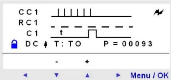 | The preset value is 93 (the maximum number of vehicles allowed in this car park).Where necessary, this value may be changed during operation. |
Clock function block H1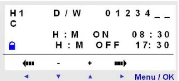 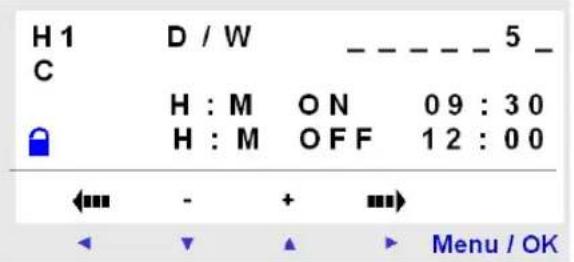 | Open hours:Monday to Friday from 8:30 am to 5:30 pm.Saturdays from 9:30 am to 12:00 noon.Closed all day Sundays.Two ranges are used. |
Timer function block T1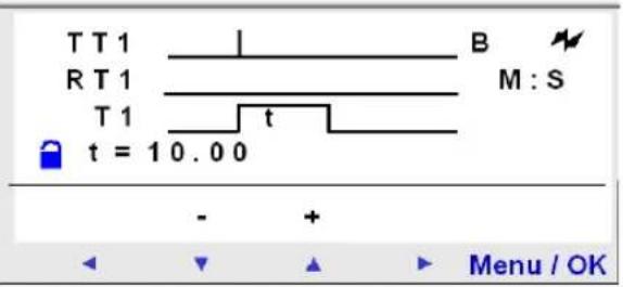 | Car park lighting timer: 10 minutes. |
Analog function block A1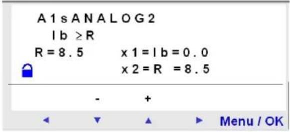 | Compares the measured CO2 level with the threshold value: 8.5 V. |
Timer function block T2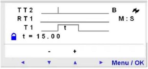 | Fan operating duration if the CO2 threshold is exceeded. 15 minutes. |
Part V Diagnostics
Chapter 21
Diagnostics
Subject of this Chapter This chapter will help you find solutions to operating problems. What Is in This Chapter? This chapter contains the following topics:| Topic Page | |
| Smart Relay Messages 180 | |
| Frequently Asked Questions 181 |
Smart Relay Messages
Description
Here is detailed information on the error messages that are returned by the smart relay, their possible causes and how to remedy the problem.Error Messages
The table below lists the error messages that a smart relay could return. These messages generally indicate incompatible actions.| Message Cause | Corrective action | |
| NO PARAMETER | No parameter is available (the diagram does not include elements with parameters). | |
| TRANSF.ERR. | A transfer was in progress and the link with the PC was interrupted. | Refer to the documentation for the programming software. |
| TRANSFER ERROR: NO MEMORY | A transfer to the non-volatile memory was requested and the non-volatile memory is not present or incorrectly inserted. | Verify the presence and correct location of the non-volatile memory. |
| TRANSFER ERROR: CONFIG INCOMPAT | The program to transfer does not match the characteristics of the target smart relay, for example: Clock, analog input, software version. | Verify the origin of the program to transfer and choose a program that is compatible with the appropriate smart relay. |
| TRANSFER ERROR: VERSION. INCOMPAT | This error is detected if one of the versions of the smart relay does not correspond to the firmware, LD or FBD functions. | Verify the firmware version. |
| Outputs are displayed flashing on the main screen | One or more static outputs have short-circuited or overloaded. | Remove the cause of the error, then stop the smart relay before selecting RUN mode again. |
Frequently Asked Questions
Frequently Asked Questions
Here below are the most frequently asked questions and their answers:| Question Answer | |
| I cannot access some parameters. | Refer to the documentation to find out whether these elements can be changed. Example of an element that cannot be changed: Counter function block counting direction. This element is only accessible by wiring in a ladder diagram line. |
| I still cannot access some parameters. | To access the parameters, you must use the navigation keys and to position the cursor above them. The ▼ and ▲ are used to change these values. Then press Menu/OK to confirm the changes. |
| I cannot RUN my smart relay even though I enable the RUN/STOP option in the main menu using the Menu/OK key. | Verify whether the error symbol is displayed in the contextual menu line. Remove the cause of the error in order to RUN the smart module. |
| I would like to change my diagram lines but the Menu/OK key no longer works. | Ensure that the smart relay is stopped. Modifications in RUN mode are not allowed. |
| When I try to change my diagram lines, the smart relay shows me a screen with only line numbers (LINE No.). Have I lost my work? | Not necessarily, this situation may occur when 4 consecutive blank lines have been inserted at the start of the ladder diagram or between the command lines. |
| I have a ladder diagram that uses the Z key (▼,▼,▲) for a pushbutton. I would like to test it but when I display the diagram dynamically, my Z key is no longer operational. Can I make it work? | No this is impossible. |
| I generated a ladder diagram on a smart relay with a clock. Can I use a backup memory to transfer it to a smart relay without clock? | No this is impossible. |
| When entering a ladder diagram, the clock function blocks do not appear when choosing the contacts. Is this normal? | Verify whether the smart relay has a clock as the clock function block is only accessible for those references. |
| When entering a ladder diagram, the analog function blocks do not appear when choosing the contacts. Is this normal? | Verify whether the smart relay has analog inputs as the analog function block is only accessible for those references. |
| I cannot use more than 120 ladder lines or I cannot use more than 16 Timers, counters, auxiliary relays. | The firmware of your module is not up-to-date. It is not necessary to exchange your smart relay. You can update the firmware using Zelio soft (see Zelio Logic Programming Guide, ). |
Appendices
Appendix A
Compatibility
Subject of this Chapter
This appendix provides information on the compatibility between the versions of the firmware, the versions of the programming software, the available functions and the different memory cartridges.What Is in This Chapter?
This chapter contains the following topics:| Topic Page | |
| Zelio Soft 2 Software Version Versus Functions 186 | |
| Compatibility between the memory cartridges and the version of the firmware on the smart relay | 187 |
Zelio Soft 2 Software Version Versus Functions
The following table shows the functions available depending on the Zelio Soft 2 software version.| Functions Zelio Soft 2 software version | |||||
| V2.xx V3.xx | V4.xx V5.0 | V5.1 | |||
| LD language | |||||
| Maximum number of program lines -- 120 | 240^(1) | 240^(1) | |||
| Number of auxiliary relays -- 28 | 56^(2) | 56^(2) | |||
| Number of counters -- 16 | 28^(3) | 28^(3) | |||
| Number of clocks -- 8 8 8 | |||||
| Number of timers -- 16 | 28^(4) | 28^(4) | |||
| Number of text blocks | -- 16 | 16 | 16 | ||
| Number of messages | -- 28 | 28 | 28 | ||
| FBD language | |||||
| Maximum number of function blocks -- 255 | 500 | 500 | |||
| Logic functions | Yes | Yes | Yes | Yes | Yes |
| Standard functions except Sunrise/Sunset and Suntrack | Yes | Yes | Yes | Yes | Yes |
| Sunrise/Sunset | -- Yes | Yes | Yes | ||
| Suntrack | -- Yes | Yes | Yes | ||
| SFC functions | -- Yes | Yes | Yes | ||
| Application functions (PID) | --- | - | Yes | ||
| (1) Only if there is no SR2COM01 module in the configuration. Otherwise, the maximum number of lines is 120.(2) Only if there is no SR2COM01 module in the configuration. Otherwise, the maximum number of auxiliary relays is 28.(3) Only if there is no SR2COM01 module in the configuration. Otherwise, the maximum number of counters is 16.(4) Only if there is no SR2COM01 module in the configuration. Otherwise, the maximum number of timers is 16. | |||||
Compatibility between the memory cartridges and the version of the firmware on the smart relay
Introduction
The section below describes the compatibility between the memory cartridges and the versions of the firmware on the smart relay.Compatibility of the Memory Cartridge with the Version of the firmware
The table below describes the compatibility of the memory cartridges with the version of the firmware:| Type of memory cartridge Version of firmware | compatible |
| SR2MEM01 LD Language: V2.19 or lower. | FBD Language: V2.18 or lower. |
| SR2MEM02 V3.09 or higher. |
Transferring a Program from the SR2MEM01 Memory Cartridge to the Smart Relay
In the case of a transfer of the program from the SR2MEM01 memory cartridge to the smart relay, compatibility is as follows:| Smart relay firmware language | |||
| LD FBD | |||
| Memory cartridge program language | LD Compatible if the versions of the memory cartridge and smart relay match. | The LD firmware version must be transferred to the smart relay. | |
| FBD The LD firmware version must be transferred to the smart relay. | Compatible if the versions of the memory cartridge and smart relay match. | ||
Transferring a Program from the SR2MEM02 Memory Cartridge to the Smart Relay
In the case of a transfer of the program from the SR2MEM02 memory cartridge to the smart relay, compatibility depends upon the firmware version of the smart relay that the program was loaded from, and the hardware version of the smart relay that the program is being transferred to: - If the memory cartridge was loaded from a smart relay using firmware version 4.04 or lower, then transfer is not compatible to smart relays with hardware version 1.0.08 or higher. - If the memory cartridge was loaded from a smart relay using firmware version 4.05 or higher, then transfer is compatible with all smart relays. For more information on how to check the firmware or hardware version, refer to the VERSION Menu (see page 75).Index
A
Auxiliary Relays, 95C
Clocks, 132 Compatibility Firmware, 187 Memory Cartridges, 187D
Discrete Inputs, 91 Discrete Outputs, 98F
Firmware Compatibility, 187|
inputs-outputs, 38L
LD Analog Comparator, 127 LD Change to Summer / Winter Time, 138 LD Counter Comparators, 125 LD Counters, 110 LD Fast Counter, 116 LD language Elements Analog Comparator, 127 LD Language Elements Auxiliary Relays, 95 LD language Elements Change to Summer / Winter Time, 138 LD Language Elements Clocks, 132 Counter Comparators, 125 Counters, 110 Discrete Inputs, 91 Discrete Outputs, 98 Fast Counter, 116 LCD Screen Backlighting, 137 Message, 141 Modbus I/Os, 140 TEXT, 135 Timers, 101 Zx Keys, 93 LD LCD Screen Backlighting, 137 LD TEXT, 135 LD Timers, 101M
Menu CHANGE DATE/TIME, 83 CHANGE SUMMER/WINTER, 85 CLEAR PROG., 69 CONFIGURATION, 61 DEFAULT, 79 LANGUAGE, 77 MONITORING, 57 PARAMETERS, 55 PASSWORD, 62 PROGRAMMING, 43 RUN / STOP, 59 TRANSFER, 71 VERSION, 75 WATCHDOG CYCLE, 67 Zx KEYS, 66 Modbus LD I/Os, 140Z
Zx Keys, 93
- Table of Contents
- Chapter 18 Debugging an Application.... 159
- Chapter 19 Transfer of Ladder Diagrams ..... 167
- Chapter 20 Sample Application.... 169
- Part V Diagnostics 177
- Chapter 21 Diagnostics.... 179
- Appendices 183
- Appendix A Compatibility 185
- Index 189
- Important Information
- NOTICE
- DANGER
- WARNING
- CAUTION
- PLEASE NOTE
- BEFORE YOU BEGIN
- UNGUARDED EQUIPMENT
- START-UP AND TEST
- OPERATION AND ADJUSTMENTS
- At a Glance
- Document Scope
- Validity Note
- Product Related Information
- ⚠️! DANGER
- HAZARD OF ELECTRIC SHOCK, EXPLOSION OR ARC FLASH
- ! DANGER
- POTENTIAL FOR EXPLOSION
- LOSS OF CONTROL
- EXPLOSION, FIRE, OR CHEMICAL BURNS
- Terminology Derived from Standards
- Part I
- Chapter 1
- Initial Power up and Discovering
- Presentation of the Smart Relay Front Panel
- Introduction
- Description of the Smart Relay Front Panel
- Description of the LCD
- Characteristics and Connections
- Connection to a Regulated DC Power Supply
- Connection to a Rectified Filtered Regulated Power Supply
- Prohibited Connection
- Control Keys on the Front Panel of the Smart Relay
- Description
- Shift Key
- Menu/OK Key
- Zx Keys
- Contextual Menus
- Examples
- Language Selection
- Modification of Date and Hour
- Step Action
- Part II
- Functions Accessible from the Front Panel
- Subject of this Section
- What Is in This Part?
- Chapter 2
- Overview of the Functions Accessible from the Front Panel
- Functions Accessible from the Front Panel of the Smart Relay
- Managing Menus
- Differences Between LD and FBD Modes
- Configuring Extensions
- Chapter 3
- Input/Output Screen
- Inputs-Outputs Screen
- Access to the Main Menu
- TEXT and DISPLAY screen
- Switching Between the Screens
- Modify Displayed Values
- Chapter 4 PROGRAMMING Menu
- Subject of this Chapter
- NOTE:
- What Is in This Chapter?
- Rules for Entering Ladder Diagrams
- Data Entry Rules
- Method for Entering a Contact or Coil
- Entering an Element
- Modifying an element
- Initialization
- Deleting an Element
- Entering a Link
- Entering/Modifying a Link
- Deleting a Link
- Replacing a Link with a Contact
- Entry of Function Block Parameters
- Accessibility of parameters
- Entering/Modifying Parameters of the Block
- Deletion and Insertion of Diagram Lines
- Deletion
- Insertion
- Chapter 5 PARAMETERS Menu
- PARAMETERS Menu
- LD Mode
- FBD Mode
- Parameter Modification
- Parameters in RUN Mode
- Chapter 6 MONITORING Menu
- MONITORING Menu
- Chapter 7 RUN/STOP Menu
- RUN/STOP Menu
- Startup
- Off
- Smart Relays Without Screen
- Chapter 8 CONFIGURATION Menu
- PASSWORD Menu
- Defining Password
- Removing Password
- Modifying Password
- FILTER Menu
- Filter-Type Selection
- Zx KEYS Menu
- Zx Keys in RUN Mode
- WATCHDOG CYCLE Menu
- Actions
- Cycle Time
- WATCHDOG Configuration
- Chapter 9
- CLEAR PROGRAM Menu
- CLEAR PROG Menu.
- Clearing the Program
- Chapter 10
- TRANSFER Menu
- Module → Backup Memory Transfer
- Backup Memory → Module Transfer
- Possible Errors
- Application incompatible with firmware on the smart relay
- Use of SR2MEM01 and SR2MEM02
- Consequently:
- Chapter 11 VERSION Menu
- VERSION Menu
- Chapter 12
- LANGUAGE Menu
- Chapter 13 DEFAULT Menu
- DEFAULT Menu
- Reset to Zero of the Error Counter
- Error Types
- Chapter 14
- CHANGE DATE/TIME Menu
- Clock Calibration
- Clock Configuration
- Chapter 15
- CHANGE SUMMER/WINTER Menu
- Configuration of the Time Change
- Part III
- LD Language
- Chapter 16
- LD Language Elements
- Composition of Ladder Diagrams
- Sample Ladder Diagram
- Discrete Inputs
- Use as a Contact
- Modification of the state of a contact
- Example
- Deactivation of Zx Keys
- Auxiliary Relays
- Use as a Coil
- Reset coil:
- Modifying the State of a Coil or a Contact
- Latching
- Discrete Outputs
- Timers
- Use of Coils
- Reset input:
- Configuration from Front Panel
- Type of timer:
- Parameter lock:
- Latching:
- Timing Diagrams
- Example 1
- Counters
- Normally closed:
- Type of counting:
- Preset value:
- Counter Value
- Fast Counter
- Cycle type:
- Duration of pulse:
- Counter Comparators
- Configuration from the Front Panel
- Analog Comparators
- Clocks
- Combining Operating Ranges
- TEXT
- Used as a Coil
- Parameter
- LCD Screen Backlighting
- Change to Summer / Winter Time
- Parameters
- Modbus Inputs/Outputs
- Words to be sent to master
- Words sent by the master
- Message
- Use of the Coil
- Part IV
- Creating and Debugging an Application
- Chapter 17
- Implementing an Application
- Presentation of Ladder Diagrams
- Module Wiring
- Application Operation
- Using the Reverse Function
- Practical Example
- General Case
- Notation Used by the Smart Relay
- Equivalences Between Notations
- Other Elements
- Application: Implementing a Two-way Switch
- Go to the Programming Screen
- Entering the Contacts in the First Line
- Entering the Coil and Linking it to the Contacts
- Entering the Contacts in the Second Line
- Linking the Second Line to the First
- Launching the Program
- The Main Points
- Chapter 18
- Debugging an Application
- Smart Relay Module in RUN Mode
- Viewing Status:
- Run Mode Ladder Diagrams
- Viewing Ladder Diagrams
- Modifying Ladder Diagrams
- Using Z Keys as Pushbuttons
- Run Mode Function Block Parameters
- Presentation
- Accessing / Modifying parameters
- Run Mode Menus
- Smart Relay Reaction to a Power Outage
- Locked Coil Control
- Chapter 19
- Transfer of Ladder Diagrams
- Transferring Ladder Diagrams
- Transferring an Application
- Chapter 20
- Sample Application
- Specifications
- Objective
- Automatic Gate
- Counting Vehicles
- Open Time
- Removal of Gasses
- Lighting
- Manual Counting
- Specification Analysis
- Inputs
- Function keys
- Outputs
- Special function blocks
- Hardware Solution
- Implementing the Solution
- Implementing the Ladder Diagram
- Configuring the Function Blocks
- Part V Diagnostics
- Chapter 21
- Diagnostics
- Smart Relay Messages
- Error Messages
- Frequently Asked Questions
- Appendices
- Appendix A
- Compatibility
- Zelio Soft 2 Software Version Versus Functions
- Compatibility between the memory cartridges and the version of the firmware on the smart relay
- Compatibility of the Memory Cartridge with the Version of the firmware
- Transferring a Program from the SR2MEM01 Memory Cartridge to the Smart Relay
- Transferring a Program from the SR2MEM02 Memory Cartridge to the Smart Relay
- Index
- A
- C
- D
- F
- |
- L
- M
- Z
Brand : SCHNEIDER
Model : SR3XT141BD
Category : Uncategorized