
EK630 - Tripod E-Image - Free user manual and instructions
Find the device manual for free EK630 E-Image in PDF.


| Product Type | Tripod with Fluid Head |
| Brand | E-Image |
| Model | EK630 |
| Bowl Size | 75 mm |
| Head Net Weight | 4.8 kg |
| Tripod Net Weight (AT630) | 2.9 kg |
| Head Load Capacity | 4 kg |
| Tripod Payload | 40 kg |
| Height Range | 780 - 1380 mm |
| Transport Length | 820 mm |
| Material (Legs) | Aluminum |
| Drag | Fixed/Variable |
| Counterbalance | Fixed |
| Tilt Range | +90° to -50° |
| Temperature Range | -40°C to 80°C |
| Pan Bar | Included |
| Mid-Level Spreader | Adjustable, included |
| Retractable Easy Hook | Yes |
| Anti-Slide Feet | Rubber with retractable spikes |
| Quick Release Plate | Included, with locking knob and insurance button |
| Bubble Level | Yes, on head |
| Maintenance | Clean with mild detergent, store in carry bag, avoid seawater |
| Safety | Engage locks, check payload, don't use below -30°C or above 60°C |
Frequently Asked Questions - EK630 E-Image
User questions about EK630 E-Image
0 question about this device. Answer the ones you know or ask your own.
Ask a new question about this device
Download the instructions for your Tripod in PDF format for free! Find your manual EK630 - E-Image and take your electronic device back in hand. On this page are published all the documents necessary for the use of your device. EK630 by E-Image.
USER MANUAL EK630 E-Image
Address: No.373 South Hangyong Rd, Luotuo Industry zone, Zhenhai,
Ningbo, China. 315202
Tel:86-574-55681753,86-574-55681675
Fax:86-574-86590078
E-mail: sales@eimagevideo.com
Visit www.eimagevideo.com for more information

The magic life in the image world
E-IMAGE
User's Manual
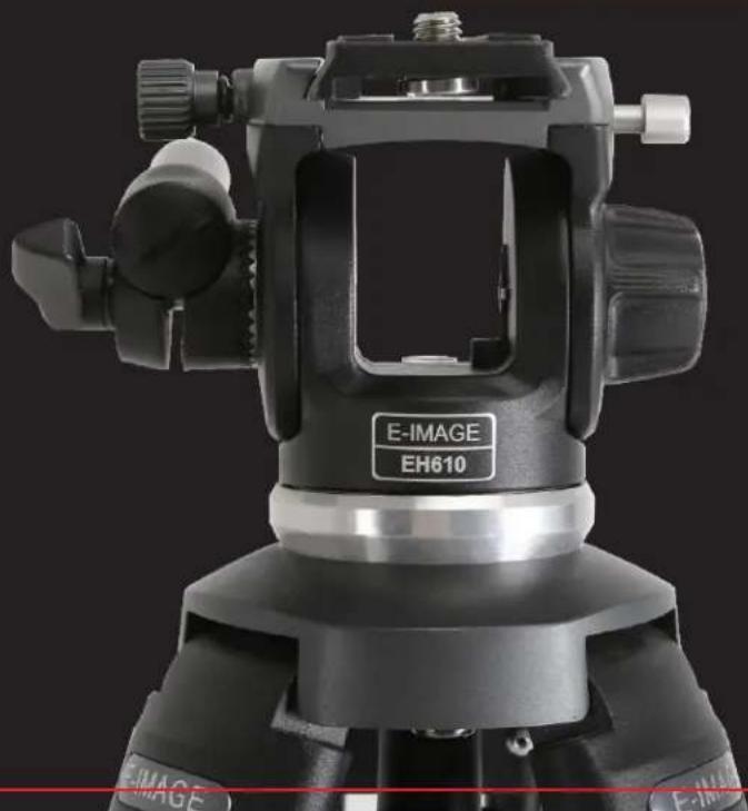
natural_image
Close-up of a black E-IMAGE camera tripod mount (no visible text or symbols on the device body)PREFACE
CONTENTS
Thanks for your purchasing E-IMAGE professional heads and tripods. As the manual is an important part of the equipment and is aimed at personal who operate and maintain the equipment. It contains detail information about the E-IMAGE heads and tripods and it's proper use. We intensely suggest you to read the manual carefully, to familiarize yourself with its many functions. It also include a section about safety and maintenance, which will help you keep the equipment in prefect condition and prolong the using period.
Please keep this manual for future reference.

Fluid head specification....1
Tripod specification....7
Maintenance....15
Notice & Warning 16
PARTS (EH610)
| Model No. | Bowl size | Net weight | Load capacity | Grades of drag | Counterbalance | Tilt range | Temperature range |
| EK610 | 65mm | 3.5kg | 3kg | Fixed | Fixed | +90° ~ -60° | -40°C ~ 80°C |
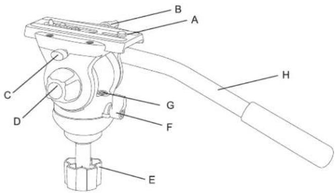
A Quick release plate
B Plate locking knob
C Insurance button
D Tilt drag adjusting knob
E Bowl locking knob
F Pan locking knob
G Bubble level
H Pan bar
1
SET UP & USE (EH610)
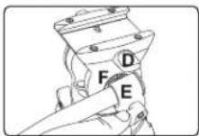
1. Install Pan Handle
Place the pan handle "E" in the desired position on the pan handle mounting rosette "F", then secure it by tightening pan handle locking thumb screw "D".
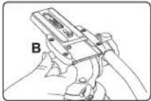
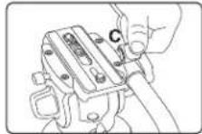
2. Removing quick release plate
Loosen the quick release plate locking knob "B", then press the quick release plate release button "C" while sliding the plate to wards the back of the head.
3. Adjusting tilt position
Loosen the tilt locking knob "G" to change tilt position. Tighten the knob to lock the tilt position.
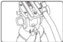
4. Adjusting pan position
Loosen the pan locking knob "I" to change the pan position. Tighten theknob to lock the pan position.
2
PARTS (EH630)
| Model No. | Bowl size | Net weight | Load capacity | Grades of drag | Counterbalance | Tilt range | Temperature range |
| EK630 | 75mm | 4.8kg | 4kg | Fixed/Variable | Fixed | +90° ~ -50° | -40°C ~ 80°C |
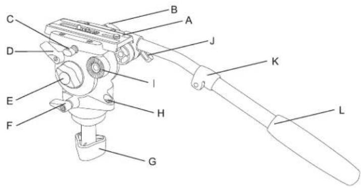
A...... Quick release plate
B Plate locking knob
C...... Insurance button
D.... Tilt locking knob
E...... Tilt drag adjusting knob
F Pan locking knob
G Bowl locking knob
H Bubble level
| Connection part of handle &head
J Pan bar locking knob
K....Length adjusting knob
L Pan bar
3
PARTS (EH650)
| Model No. | Bowl size | Net weight | Load capacity | Grades of drag | Counterbalance | Tilt range | Temperature range |
| EK650 | 75mm | 4.1kg | 5kg | Fixed/Variable | Fixed | +90° ~ -60° | -40°C ~ 80°C |
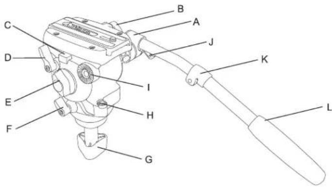
A…… Quick release plate
B Plate locking knob
C Insurance button
D.... Tilt locking knob
E.... Tilt drag adjusting knob
F Pan locking knob
G...... Bowl locking knob
H Bubble level
| Connection part of handle&head
J....Pan bar locking knob
K....Length adjusting knob
L Pan bar
4
SET UP & USE (EH630/EH650)
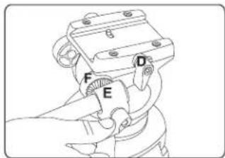
1. Install Pan Handle
Place the pan handle 'E' in the desired position on the pan handle mounting rosette 'F', then secure it by tightening pan handle locking thumb screw 'D'.
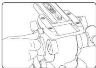
2. Removing quick release plate
Loosen the quick release plate locking knob "B", then press the quick release plate release button 'C' while sliding the plate to wards the back of the head.
natural_image
Line drawing of a hand operating a mechanical device with no visible text or symbols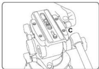
natural_image
Technical line drawing of a mechanical assembly with labeled component C (no text or symbols beyond label)5
SET UP & USE (EH630/EH650)
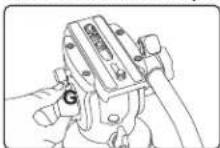
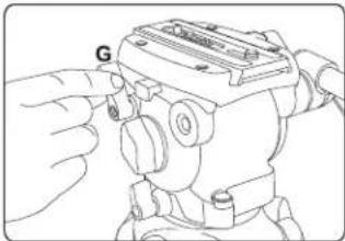
3. Adjusting tilt position
Loosen the tilt locking knob "G" to change tilt position. Tighten the knob to lock the tilt position.
natural_image
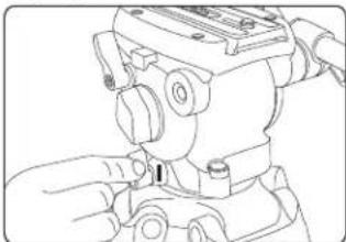
Line drawing of a mechanical device with a hand adjusting a button labeled 'G' (no text or symbols present)4. Adjusting pan position
Loosen the pan locking knob "I" to change the pan position. Tighten theknob to lock the pan position.
natural_image
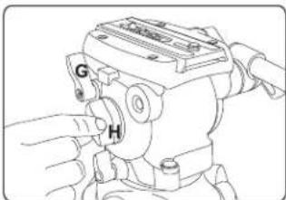
Line drawing of a mechanical assembly with hands operating a component (no text or symbols)5.Tilt Drag Adjustment
Increase tilt drag by turning the tilt drag adjustment knob 'G' clock wise(as if tightening a screw). Reduce the tilt drag by turning the knob 'H', counter-clockwise (as if loosening a screw).
6
TRIPOD

EIMAGE GENTING series is upgraded generation of EIMAGE tripods. The tripod legs are all made up of high grade aluminum or carbon fiber material. With newly designed lock system and patent locking mechanism, it provides excellent hand feeling, quick and secure locking. With standard 75mm or 100mm bowl, you can attach any professional video heads on the tripods. All tripods can match with mid spreader or ground spreader, just up to your needs. They also can be installed on dollies to provide fast moving. The new tripods are compact when closed, easy to transport with carrying case.
PARTS (AT610)
| Model No. | Bowl Size | Descrition | Height Range | Transport length | Weight | Payload rang |
| AT610 | 65mm | Aluminum | 650-1510mm | 695mm | 3.3kg | 40kg |
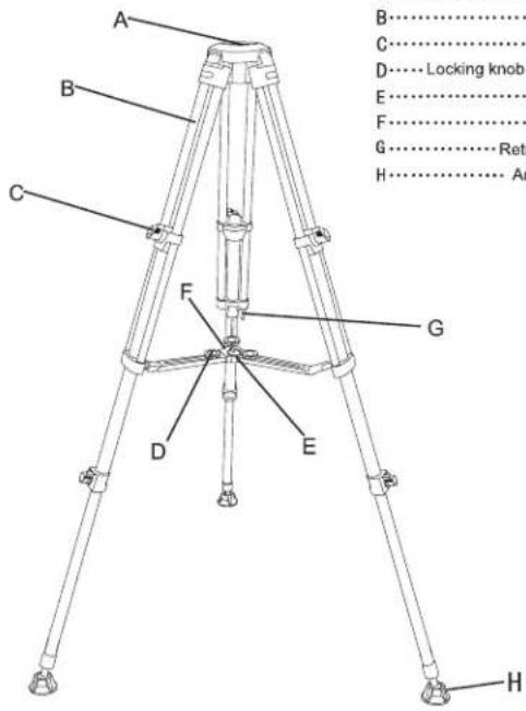
A...... Bowl base
B......Leg tube
C Locking knob
D……Locking knob of ground speaker
E....Pull ring
F...... Mid spreader
G......Retractable easy hook
H.... Anti-slide rubber pad
SET UP & USE (AT610)
1. Loose lock leg tube
Loose: turn locking knob "C" anti-clockwise
Lock: turn locking knob "C" clockwise
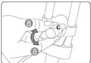
Important message: before unfold the tripod, please loose all the locking knobs "C", then adjust it to your requested length and lock it.
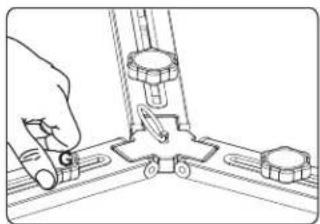
2. Adjusting the Mid-Level Spreader
To make adjustments to the mid-level spreader, loosen the locking knob "G" and reposition the leg attached to that section of the spreader. When the adjustment is made, tighten the knob to re-secure the spreader.
natural_image
Line drawing of a mechanical assembly with a hand holding a tool and a bracket (no text or symbols)
USE UP & USE (AT610)
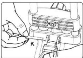
If you don't need mid-level spreader, pull out the locking bolts "K" of 3 arms and remove it.
natural_image
Mechanical assembly diagram showing hands operating a component with a labeled part 'K' (no text or symbols beyond the label)3. Anti-slide rubber feet
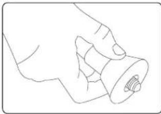
Rubber Feet with Retractable Spikes.
natural_image
Line drawing of a hand holding a cylindrical object (no text or symbols)
PARTS (AT630)
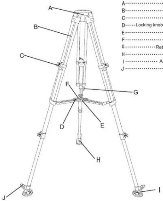
| Model No. | Bowl Size | Descrition | Height Range | Transport length | Weight | Payload rang |
| AT630 | 75mm | Aluminum | 780-1380mm | 820mm | 2.9kg | 40kg |
11
PARTS (GA752S)
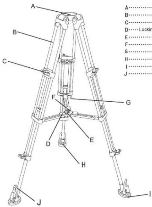
| Model No. | Bowl Size | Descrition | Height Range | Transport length | Weight | Payload rang |
| GA752S | 75mm | Aluminum | 780-1380mm | 820mm | 2.6kg | 40kg |
12
SET UP & USE (AT630/GA752S)
1. Loose lock leg tube
Loose: turn locking knob "C" anti-clockwise
Lock: turn locking knob "C" clockwise
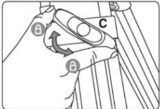
Important message: Adjust tripod height
Loose all the locking knobs and extend the legs to your request height, then lock knobs tightly.
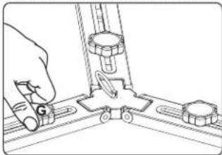
2. Adjusting the Mid-Level Spreader
To make adjustments to the mid-level spreader, loosen the locking knob "G" and reposition the leg attached to that section of the spreader. When the adjustment is made, tighten the knob to re-secure the spreader.
natural_image
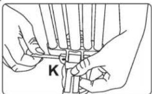
Line drawing of a mechanical assembly with a hand operating a tool (no text or symbols)If you don't need mid-level spreader, pull out the locking bolts "K" of 3 arms and remove it.
13
SET UP & USE (AT630/GA752S)
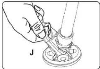
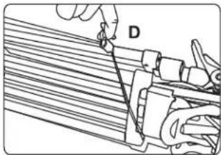
5. Install & Remove ground spreader
Illustration as follow pictures, pull the pad-removing tab "J", separate anti-sliding pad with leg.
natural_image
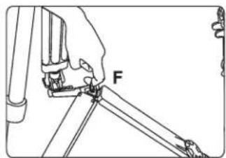
Illustration of a hand using a tool to adjust or install a mechanical component (no text or symbols visible)6.Folding tripod
a: Loose the locking knobs of each stages and adjust the legs to minimum length, then locking all the knobs.
b. Adjust the mid-spreader or ground-spreader to minum length, then locking all the knobs.
c. One hand catch the bowl base, another hand pull the ring of ground spreader "F" and fold it. Then pull out retractable easy hook "D" and wrap around legs and bind them together.
14
MAINTENANCE
NOTICE & WARNING
Daily maintenance:
Storage and transport:
- When not using head for a long time, please turn all the knobs to the minimum.
- When not using tripod, please don't place vertically to avoid the broken
- When not using tripod or transportation, please keep it in the carry bag.
Function inspection:
- Please check the tripod payload and head locking condition, in order to avoid the accident
- Please check and adjust tripod and head locking condition regularly, in order to increase service life.
Cleaning & Maintenance:
-
- Using a regular with a lint-free cloth to clean tripods.
-
- Please keep it in carrying case if not use it for long time.
• 3. Using a semi-stiffe brush or vacuum
- Please keep it in carrying case if not use it for long time.
Always engage safety locks and devices where applicable on the products.
Don't use product at temperatures less than -30^ or more than 60^ . Cleaning with mild detergent and a soft cloth. Remove dust and sand from all locking threads and sliding segments. Dry the product after use in wet conditions.
IMPORTANT: Not recommended to use in seawater
If any questions during using process, please read the instruction carefully or ask help from your local distributor.
In the event on the product becoming defective, the unit should be returned to an authorized E-IMAGE service agent.


- E-IMAGE
- PREFACE
- CONTENTS
- PARTS (EH610)
- SET UP & USE (EH610)
- Install Pan Handle
- Removing quick release plate
- Adjusting tilt position
- Adjusting pan position
- SET UP & USE (EH630/EH650)
- 5.Tilt Drag Adjustment
- TRIPOD
- PARTS (AT610)
- SET UP & USE (AT610)
- Loose lock leg tube
- Adjusting the Mid-Level Spreader
- USE UP & USE (AT610)
- Anti-slide rubber feet
- SET UP & USE (AT630/GA752S)
- Install & Remove ground spreader
- 6.Folding tripod
- MAINTENANCE
- NOTICE & WARNING
- Daily maintenance:
Brand : E-Image
Model : EK630
Category : Tripod